


Color Video
4-162-900-13(1)
Printer
Instructions for Use
Before operating the unit, please read this manual thoroughly
and retain it for future reference.
UP-25MD
© 2010 Sony Corporation
Owner’s Record
The model and serial numbers are located at the rear.
Record these numbers in the space provided below.
Refer to these numbers whenever you call upon your Sony
dealer regarding this product.
Model No. ____________________
Serial No. ____________________
WARNING
To reduce the risk of fire or electric shock, do not
expose this apparatus to rain or moisture.
To avoid electrical shock, do not open the
cabinet. Refer servicing to qualified personnel
only.
THIS APPARATUS MUST BE EARTHED.
All interface cables used to connect peripherals must be
shielded in order to comply with the limits for a digital
device pursuant to Subpart B of Part 15 of FCC Rules.
For the customers in Canada
This unit has been certified according to Standard CSA
C22.2 No.601.1.
For the customers in the U.S.A and Canada
When you use this product connected to 240 V single
phase, be sure to connect this product to a center tapped
circuit.
Important safeguards/notices for use in the
medical environments
1. All the equipments connected to this unit shall be
certified according to Standard IEC60601-1,
IEC60950-1, IEC60065 or other IEC/ISO Standards
applicable to the equipments.
To disconnect the main power, unplug the AC IN
connector.
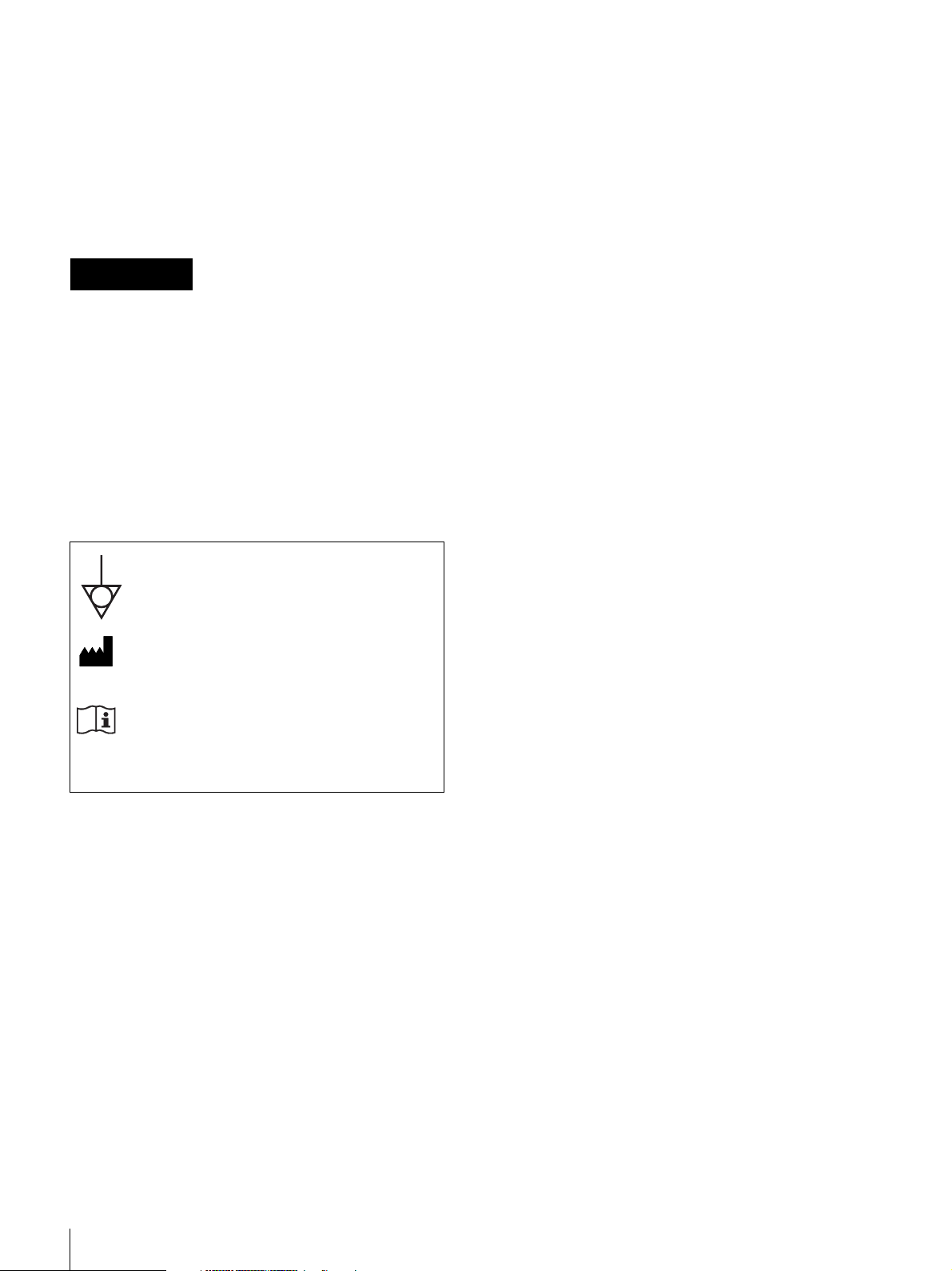
This symbol indicates the equipotential
terminal which brings the various parts of a
system to the same potential.
This symbol indicates the manufacturer, and
appears next to the manufacturer’s name and
address.
Refer to the operating instructions
Follow the directions in the operating
instructions for parts of the unit on which this
mark appears.
For the customers in the U.S.A.
This equipment has been tested and found to comply with
the limits for a Class A digital device, pursuant to Part 15
of the FCC Rules. These limits are designed to provide
reasonable protection against harmful interference when
the equipment is operated in a commercial environment.
This equipment generates, uses, and can radiate radio
frequency energy and, if not installed and used in
accordance with the instruction manual, may cause
harmful interference to radio communications. Operation
of this equipment in a residential area is likely to cause
harmful interference in which case the user will be
required to correct the interference at his own expense.
2. Furthermore all configurations shall comply with the
system standard IEC60601-1-1. Everybody who
connects additional equipment to the signal input part
or signal output part configures a medical system, and
is therefore, responsible that the system complies with
the requirements of the system standard IEC60601-1-1.
If in doubt, consult the qualified service personnel.
3. The leakage current could increase when connected to
other equipment.
4. For this particular equipment, all accessory equipment
connected as noted above, must be connected to mains
via an additional isolation transformer conforming with
the construction requirements of IEC60601-1 and
providing at least Basic Insulation.
5. This equipment generates, uses, and can radiate radio
frequency energy. If it is not installed and used in
accordance with the instruction manual, it may cause
interference to other equipment. If this unit causes
interference (which can be determined by unplugging
the power cord from the unit), try these measures:
Relocate the unit with respect to the susceptible
equipment. Plug this unit and the susceptible
equipment into different branch circuit.
Consult your dealer. (According to standard IEC60601-12 and CISPR11, Class B, Group 1)
You are cautioned that any changes or modifications not
expressly approved in this manual could void your
authority to operate this equipment.
2
Important EMC notices for use in the medical environments
• The UP-25MD needs special precautions regarding
EMC and needs to be installed and put into service
according to the EMC information provided in this
instructions for use.
• The portable and mobile RF communications equipment
such as cellular phones can affect the UP-25MD.
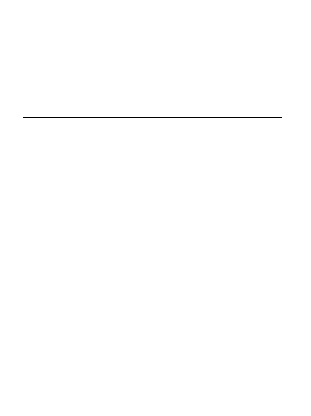
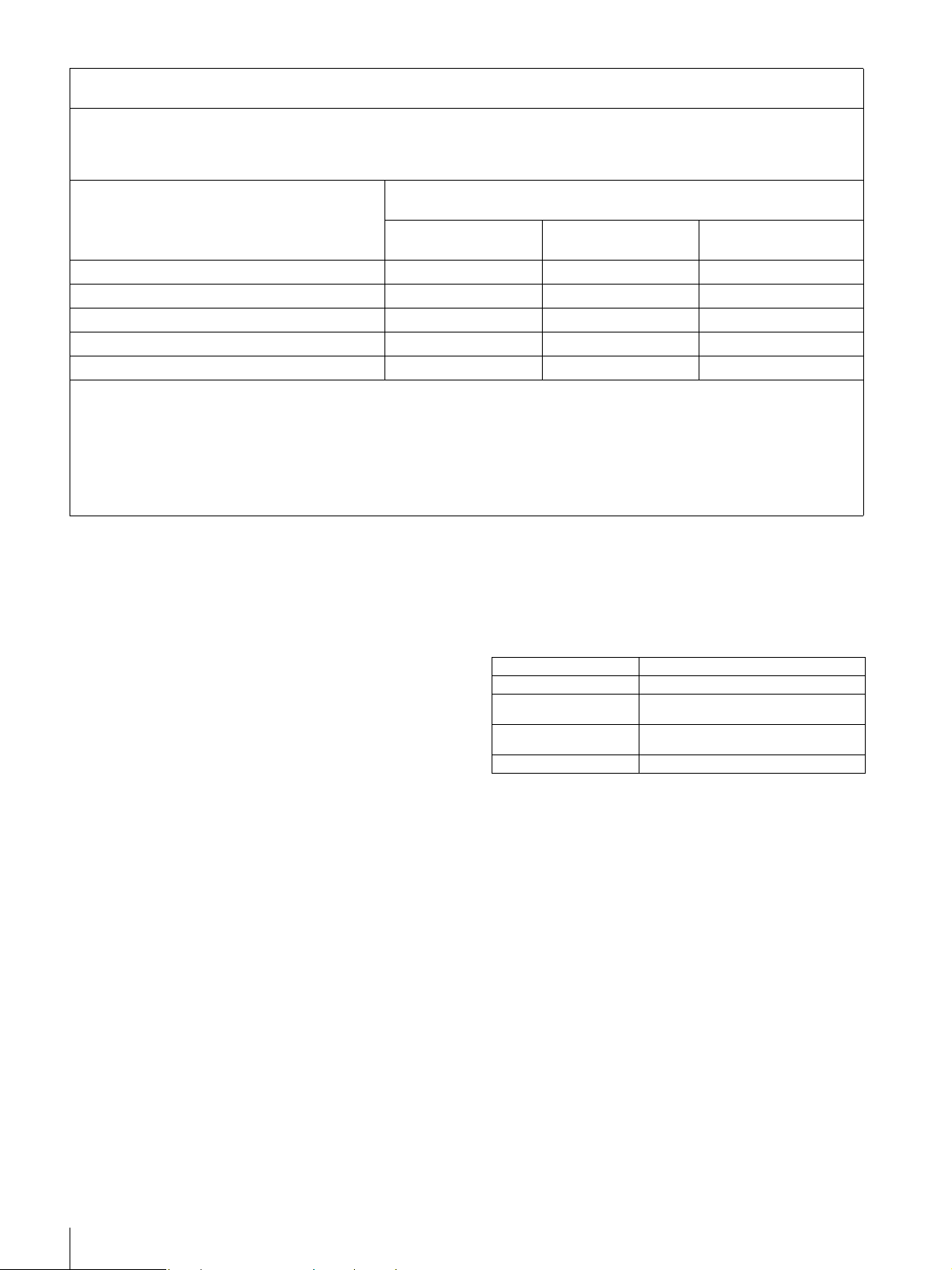
Guidance and manufacturer’s declaration-electromagnetic emissions
The UP-25MD is intended for use in the electromagnetic environment specified below.
The customer or the user of the UP-25MD should assure that it is used in such an environment.
Emission test Compliance Electromagnetic environment-guidance
RF emissions
CISPR 11
RF emissions
CISPR 11
Harmonic emissions
IEC 61000-3-2
Voltage fluctuations/
flicker emissions
IEC 61000-3-3
Group 1
Class B
Class A
Complies
Warning
The use of accessories and cables other than those
specified, with the exception of replacement parts sold by
Sony Corporation, may result in increased emissions or
decreased immunity of the UP-25MD.
The UP-25MD uses RF energy only for its internal function.
Therefore, its RF emissions are very low and are not likely
to cause any interference in nearby electronic equipment.
The UP-25MD is suitable for use in all establishments,
including domestic establishments and those directly
connected to the public low-voltage power supply network
that supplies buildings used for domestic purposes.
Warning
If the UP-25MD should be used adjacent to or stacked with
other equipment, it should be observed to verify normal
operation in the configuration in which it will be used.
3
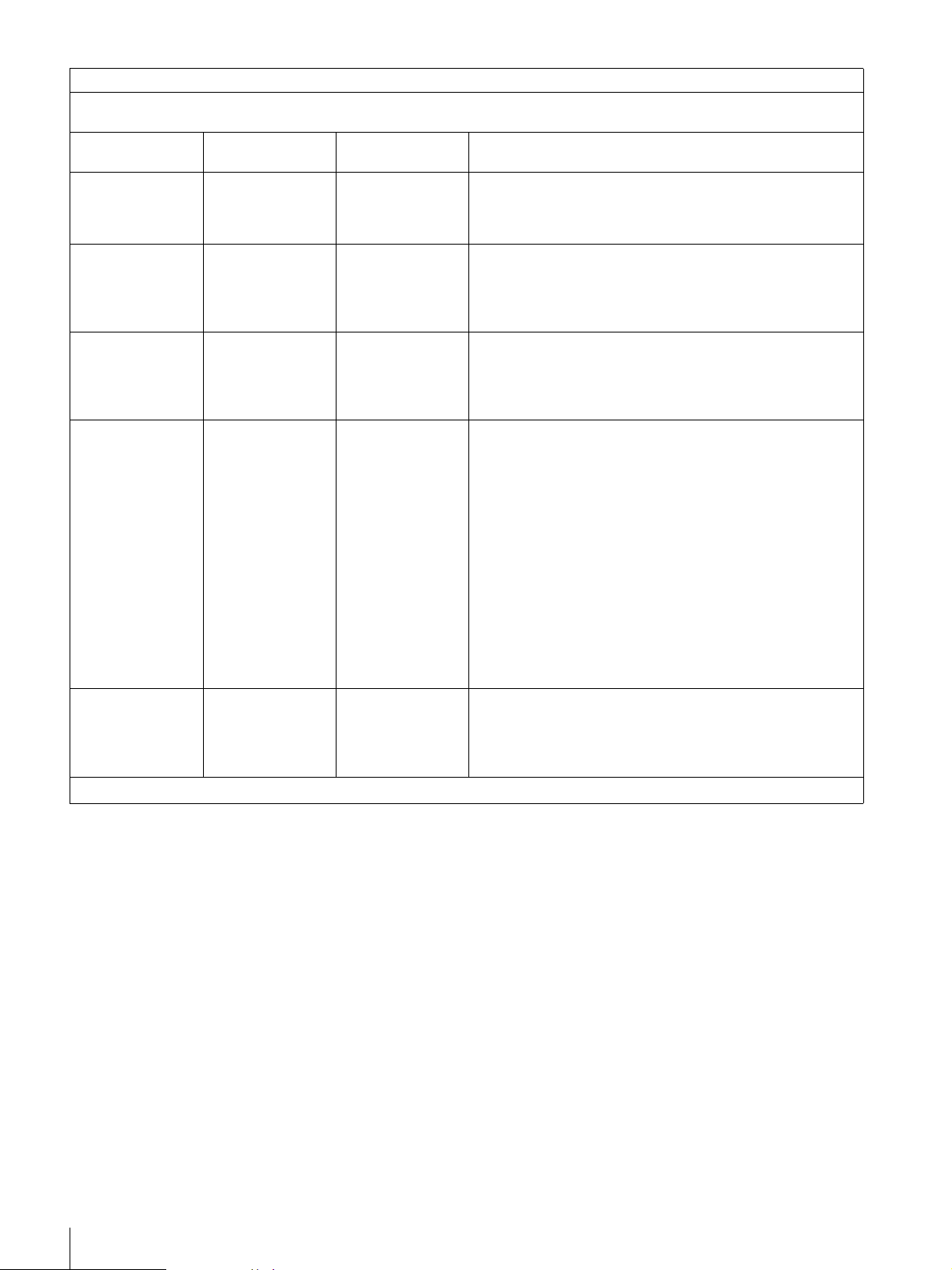
Guidance and manufacturer’s declaration - electromagnetic immunity
The UP-25MD is intended for use in the electromagnetic environment specified below. The customer or the user of the
UP-25MD should assure that it is used in such as environment.
Immunity test
Electrostatic
discharge (ESD)
IEC 60601 test
level
±6 kV contact
±8 kV air
Compliance level Electromagnetic environment-guidance
±6 kV contact
Floors should be wood, concrete or ceramic tile. If floors are
covered with synthetic material, the relative humidity should
±8 kV air
be at least 30%.
IEC 61000-4-2
Electrical fast
transient/burst
±2 kV for power
supply lines
±2 kV for power
supply lines
Mains power quality should be that of a typical commercial or
hospital environment.
IEC 61000-4-4
Surge
IEC 61000-4-5
Voltage dips, short
interruptions and
voltage variations
on power supply
input lines
IEC 61000-4-11
Power frequency
(50/60 Hz)
magnetic field
IEC 61000-4-8
NOTE: U
is the a.c. mains voltage prior to application of the test level.
T
±1 kV for input/
output lines
±1 kV differential
mode
±2 kV common
mode
< 5% U
T
(> 95% dip in U
for 0.5 cycle
40% UT
(60% dip in U
for 5 cycles
70% UT
(30% dip in U
for 25 cycles
< 5% U
T
(> 95% dip in U
for 5 sec
±1 kV for input/
output lines
±1 kV differential
mode
±2 kV common
mode
< 5% U
(> 95% dip in U
)
T
for 0.5 cycle
40% UT
(60% dip in U
)
T
for 5 cycles
70% UT
(30% dip in U
)
T
for 25 cycles
< 5% U
)
(> 95% dip in U
T
for 5 sec
Mains power quality should be that of a typical commercial or
hospital environment.
T
Mains power quality should be that of a typical commercial or
hospital environment. If the user of the UP-25MD requires
)
T
continued operation during power mains interruptions, it is
recommended that the UP-25MD be powered from an
uninterruptible power supply or a battery.
)
T
)
T
T
)
T
3 A/m 3 A/m Power frequency magnetic fields should be at least
characteristic of a typical location in a typical commercial or
hospital environment.
4
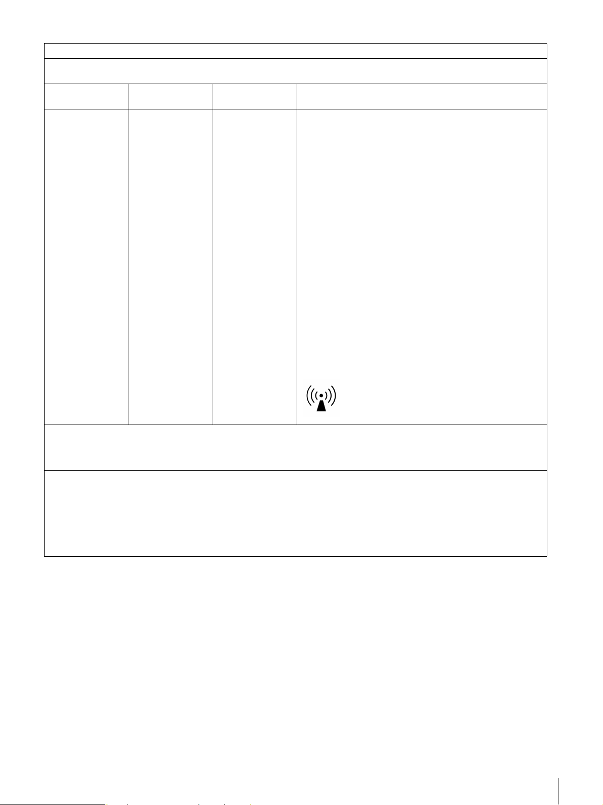
Guidance and manufacturer’s declaration - electromagnetic immunity
The UP-25MD is intended for use in the electromagnetic environment specified below. The customer or the user of the
UP-25MD should assure that it is used in such as environment.
Immunity test
IEC 60601 test
level
Compliance level Electromagnetic environment-guidance
Portable and mobile RF communications equipment should
be used no closer to any part of the UP-25MD, including
cables, than the recommended separation distance
calculated from the equation appliance to the frequency of
the transmitter.
Recommended separation distance
Conducted RF
IEC 61000-4-6
Radiated RF
IEC 61000-4-3
NOTE 1: At 80 MHz and 800 MHz, the higher frequency range applies.
NOTE 2: These guidelines may not apply in all situations. Electromagnetic propagation is affected by absorption and
reflection from structures, objects and people.
a Field strengths from fixed transmitters, such as base stations for radio (cellular/cordless) telephones and land mobile
radios, amateur radio, AM and FM radio broadcast and TV broadcast cannot be predicted theoretically with accuracy. To
assess the electromagnetic environment due to fixed RF transmitters, an electromagnetic site survey should be
considered. If the measured field strength in the location in which the UP-25MD is used exceeds the applicable RF
compliance level above, the UP-25MD should be observed to verify normal operation. If abnormal performance is
observed, additional measures may be necessary, such as reorienting or relocating the UP-25MD.
3 Vrms
150 kHz to 80 MHz
3 V/m
80 MHz to 2.5 GHz
3 Vrms
3 V/m
d = 1.2 √P
d = 1.2 √P 80 MHz to 800 MHz
d = 2.3 √P 800 MHz to 2.5 GHz
Where P is the maximum output power rating of the
transmitter in watts (W) according to the transmitter
manufacturer and d is the recommended separation distance
in meters (m).
Field strengths from fixed RF transmitters, as determined by
an electromagnetic site survey,
compliance level in each frequency range. b
Interference may occur in the vicinity of equipment marked
with following symbol:
a
should be less than the
b Over the frequency range 150 kHz to 80 MHz, field strengths should be less than 3 V/m.
5
Recommended separation distances between portable and mobile RF communications equipment and the
UP-25MD
The UP-25MD is intended for use in an electromagnetic environment in which radiated RF disturbances are controlled. The
customer or the user of the UP-25MD can help prevent electromagnetic interference by maintaining a minimum distance
between portable and mobile RF communications equipment (Transmitters) and the UP-25MD as recommended below,
according to the maximum output power of the communications equipment.
Rated maximum output power of transmitter
W
0.01 0.12 0.12 0.23
0.1 0.38 0.38 0.73
1 1.2 1.2 2.3
10 3.8 3.8 7.3
100 12 12 23
For transmitters rated a maximum output power not listed above, the recommended separation distance d in meters (m) can
be estimated using the equation applicable to the frequency of the transmitter, where P is the maximum output power rating
of the transmitter in watts (W) according to the transmitter manufacturer.
NOTE 1: At 80 MHz and 800 MHz, the separation distance for the higher frequency range applies.
Separation distance according to frequency of transmitter
150 kHz to 80 MHz
d = 1.2 √P
80 MHz to 800 MHz
m
800 MHz to 2.5 GHz
d = 1.2 √P
d = 2.3 √P
NOTE 2: These guidelines may not apply in all situations. Electromagnetic propagation is affected by absorption and
Caution
When you dispose of the unit or accessories, you must
obey the law in the relative area or country and the
regulation in the relative hospital.
Warning on power connection
Use a proper power cord for your local power supply.
1. Use the approved Power Cord (3-core mains lead) /
2. Use the Power Cord (3-core mains lead) / Appliance
If you have questions on the use of the above Power Cord
/ Appliance Connector / Plug, please consult a qualified
service personnel.
reflection from structures, objects and people.
Appliance Connector / Plug with earthing-contacts that
conforms to the safety regulations of each country if
applicable.
Connector / Plug conforming to the proper ratings
(Voltage, Ampere).
Warning on power connection for medical
use
Please use the following power supply cord.
With connectors (plug or female) and cord types other than
those indicated in this table, use the power supply cord that
is approved for use in your area.
United States and Canada
Plug Type HOSPITAL GRADE*
Cord Type Min.Type SJT
Minimum Rating for Plug
and Appliance Couplers
Safety Approval UL Listed and CSA
*Note: Grounding reliability can only be achieved when the equipment is
connected to an equivalent receptacle marked ‘Hospital Only’ or ‘Hospital Grade’.
Min.18 AWG
10A/125V
For the customers in Europe
The manufacturer of this product is Sony Corporation,
1-7-1 Konan, Minato-ku, Tokyo, Japan.
The Authorized Representative for EMC, medical devices,
and product safety is Sony Deutschland GmbH,
Hedelfinger Strasse 61, 70327 Stuttgart, Germany;
TEL: (0)711 5858 0; FAX: (0)711 5858 235.
For any service or guarantee matters, please refer to the
addresses given in separate service or guarantee
documents.
6

Table of Contents
Introduction
System Overview ....................................................... 8
Location and Function of Parts and Controls ........ 8
Front ....................................................................... 8
Rear ...................................................................... 10
Monitor Display ................................................... 10
Preparation
Supplied Accessories ............................................... 12
Connections ............................................................. 12
Connecting Video Equipment .............................. 12
Connecting the Video Monitor ............................ 13
Making Connections to Enable Remote
Control ............................................................... 14
Operation
Before Printing ........................................................ 15
Loading the Ink Ribbon ....................................... 15
Loading the Paper ................................................ 17
Selecting the Input Signal .................................... 19
Making Full-Size Image Printouts ........................ 20
Making Printouts with the Desired User Set
Number .............................................................. 23
Making Multiple Copies of Identical Printouts ... 23
Capturing Another Image While Printing ............ 25
Making Variations of Printouts ............................. 26
Selecting the Memory Mode ............................... 26
Selecting a Memory Page .................................... 28
Making a Printout of Multiple Different Reduced
Images ...................................................................... 29
Making Printouts with a Caption .......................... 33
Making Printouts With a Caption ........................ 33
Entering a Caption ............................................... 33
Deleting Images Stored in Memory ....................... 36
Setting the Function of the STOP/CLEAR
Button ................................................................ 36
Deleting Images Stored in Memory ..................... 37
Erasing the Screen Display on the Video
Monitor .................................................................... 38
Adjustment
Functions That Can be Set on Menus ................... 40
Menu Tree ................................................................ 41
Basic Menu Operations .......................................... 42
Adjusting the Color and Picture Quality .............. 45
Compensating for the Input Signals .................... 45
Matching the Video Monitor Color to the Printer
Color .................................................................. 45
Adjusting the Printout Color ................................ 46
When a Black Frame or Lines Show up on the
Printouts ............................................................. 48
Fitting the Printout to the Paper ........................... 49
Adjusting the Color Balance ................................ 50
Specifying Colors for Adjustment (HSV
Adjustment) ....................................................... 52
Configuring HDTV-Signal Inputs and
Outputs ..................................................................... 57
Selecting the Input Signal .................................... 57
Selecting the Input Signal Type ........................... 57
Selecting the Input Signal Format ....................... 57
Selecting the Synchronization Method for Input
Signals ................................................................ 58
Selecting the Output Signal Type ........................ 58
Selecting the Downconvert Method ..................... 59
Making Various Settings ........................................ 60
Assigning Functions to the Remote Control
Unit .................................................................... 60
Adjusting the Contrast of the Printer Window
Display ............................................................... 61
Setting the Tray Light .......................................... 61
Setting the Cleaning Message Display
Function ............................................................. 61
Selecting Whether the Operation and Error Tones
Sound ................................................................. 61
Setting the Baud Rate .......................................... 62
Printing Menu Configurations ............................. 62
Displaying the Ink Ribbon Type and Remaining
Amount of the Ink Ribbon ................................. 62
Registering a User Set .......................................... 62
Miscellaneous
Precautions .............................................................. 64
Safety ................................................................... 64
Cleaning ............................................................... 64
Cleaning the thermal head and the internal
rollers ................................................................. 65
Ink Ribbon and Paper ............................................ 66
About the Color Printing Pack (UPC-21S/UPC-21L)
and Laminate Color Printing Pack (UPC-24SA/
UPC-24LA) ........................................................ 66
Specifications ........................................................... 67
Troubleshooting ....................................................... 69
If Damage is Suspected ....................................... 69
Error/Warning Messages ....................................... 71
Error Messages .................................................... 71
Warning Messages ............................................... 72
Clearing a Paper Jam ........................................... 74
7
Introduction
Introduction
System Overview
The UP-25MD is a color video printer that reproduces
image inputs from video equipment and other image
output devices via simple operations.
The UP-25MD has the following features:
• High picture quality and high print resolution
The printer allows you to print out high resolution
images in full color (with 256 shades per color, a total of
more than 16,700,000 colors in all) in high resolution
print mode (approximately 423 dpi).
• Menu settings to meet your printer’s specifications
By changing the printer settings, you can print multiple
reduced images on a single page or insert captions, and
create various types of printouts. (See page 26)
Ordinary print operations can be performed using the
buttons on the printer. Depending on the operation you
want perform, you can use the window display on the
printer or a connected monitor display to configure
printer settings and perform various adjustments as
necessary.
• HDTV (high-definition television) signal input support
The printer supports both 1080i and 720p signal types,
and can automatically determine the input signal type.
When you print HDTV signals or display them on a
monitor, they are output with a 16:9 aspect ratio. You can
downconvert the signals to SDTV signals with a 4:3
aspect ratio when outputting to a monitor.
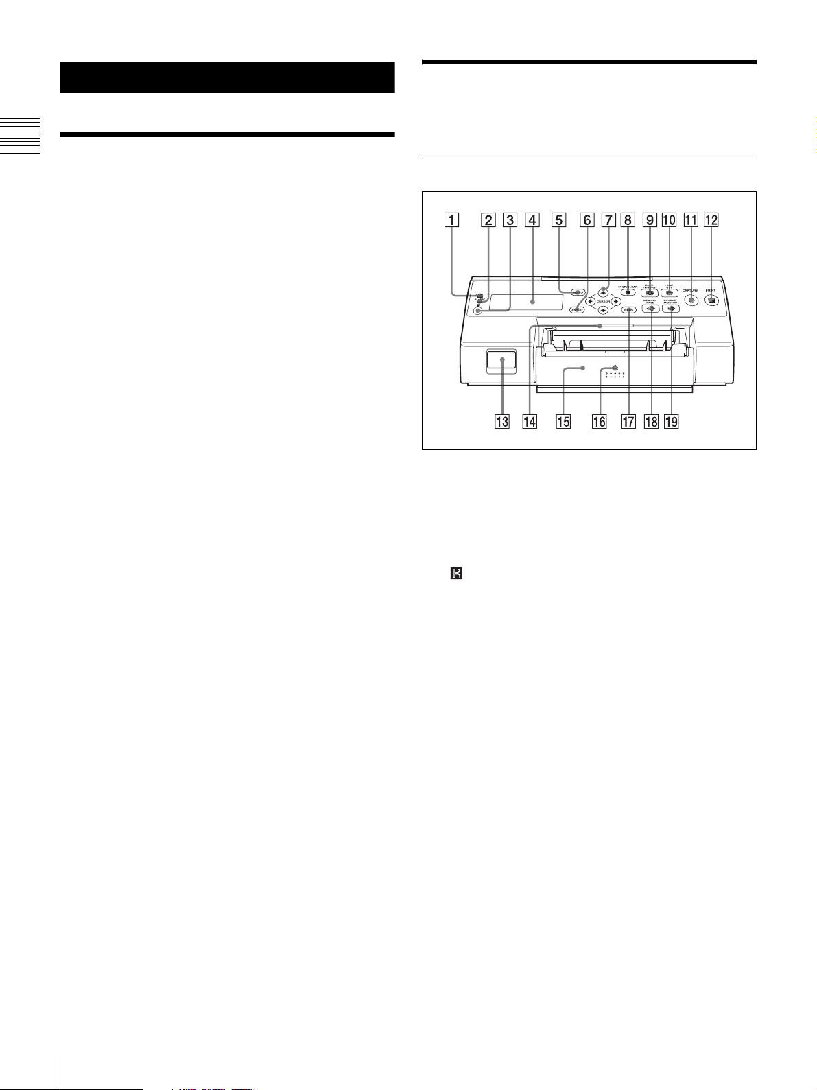
Location and Function of Parts and Controls
Front
A PRINT indicator
Lights while printing is in progress.
B ALARM indicator
Lights when an error such as a paper jam occurs.
C Remote sensor (page 14)
Aim the head of the remote control unit toward this
sensor.
D Printer window display
Displays messages similar to those that appear on the
monitor, with differences occurring due to the
narrower character display range on the printer
window.
When operating menus, the printer window also
indicates the line on which the menu cursor is
positioned.
If errors occur, error messages are displayed.
The contrast of the printer window display can be
adjusted on the SYSTEM SETUP menu. (See
page 61)
E MENU button
Press this button to display the menu or to return to the
normal screen from the menu.
F DISPLAY button (page 22, 38)
When the normal screen is displayed, pressing this
button selects whether to display screen indicators
such as Q1, A, S, etc. Each press of this button toggles
the display setting ON and OFF, and the current
setting is displayed for a few seconds when the button
8
System Overview / Location and Function of Parts and Controls
is pressed. The DISPLAY setting in the OUTPUT
SETUP menu also changes in conjunction with each
press of this button.
When the menu is displayed, pressing this button
temporarily hides the menu display on the monitor.
The menu display is hidden for as long as the button
is pressed.
N Tray light
Illuminates the output tray. (You can configure the
setting for this.) (page 61)
O Paper feed tray (page 17)
Load paper in this tray. Printouts stack in the tray
above.
Introduction
G Directional buttons (<, ,, M, m)
Use these buttons to select menu items and change
settings.
H x STOP/CLEAR button (page 36)
When printing is in progress, this button functions as
the STOP button. Press this button during continuous
printing operations to stop printing after the current
item finishes printing.
When printing is not in progress, this button functions
as the CLEAR button. Press this button to delete
images captured in memory. The images that are
deleted when the button is pressed depend on the
setting in the FUNCTION SETUP menu. If the button
is pressed while the setting is OFF, an error tone will
sound.
I MULTI PICTURE button (page 29)
Press this button during normal screen display to
select the layout (full-size, two reduced images, or
four reduced images) in which images are captured to
memory. Each press of this button switches the image
type in the following sequence: “1, 2, 4, 1...,” and the
current selection is displayed for a few seconds when
the button is pressed. The MULTI PIX setting in the
LAYOUT SETUP menu also changes in conjunction
with each press of this button.
P Z (eject) mark
Press here to eject the paper feed tray.
Q EXEC button
Use this button to confirm a menu setting.
R MEMORY PAGE button (page 25, 28, 37)
Press this button to select the memory page to use.
S SOURCE/MEMORY button
Press this button to select the source for images that
are output to the monitor. Each press of this button
toggles between memory images and input source
images.
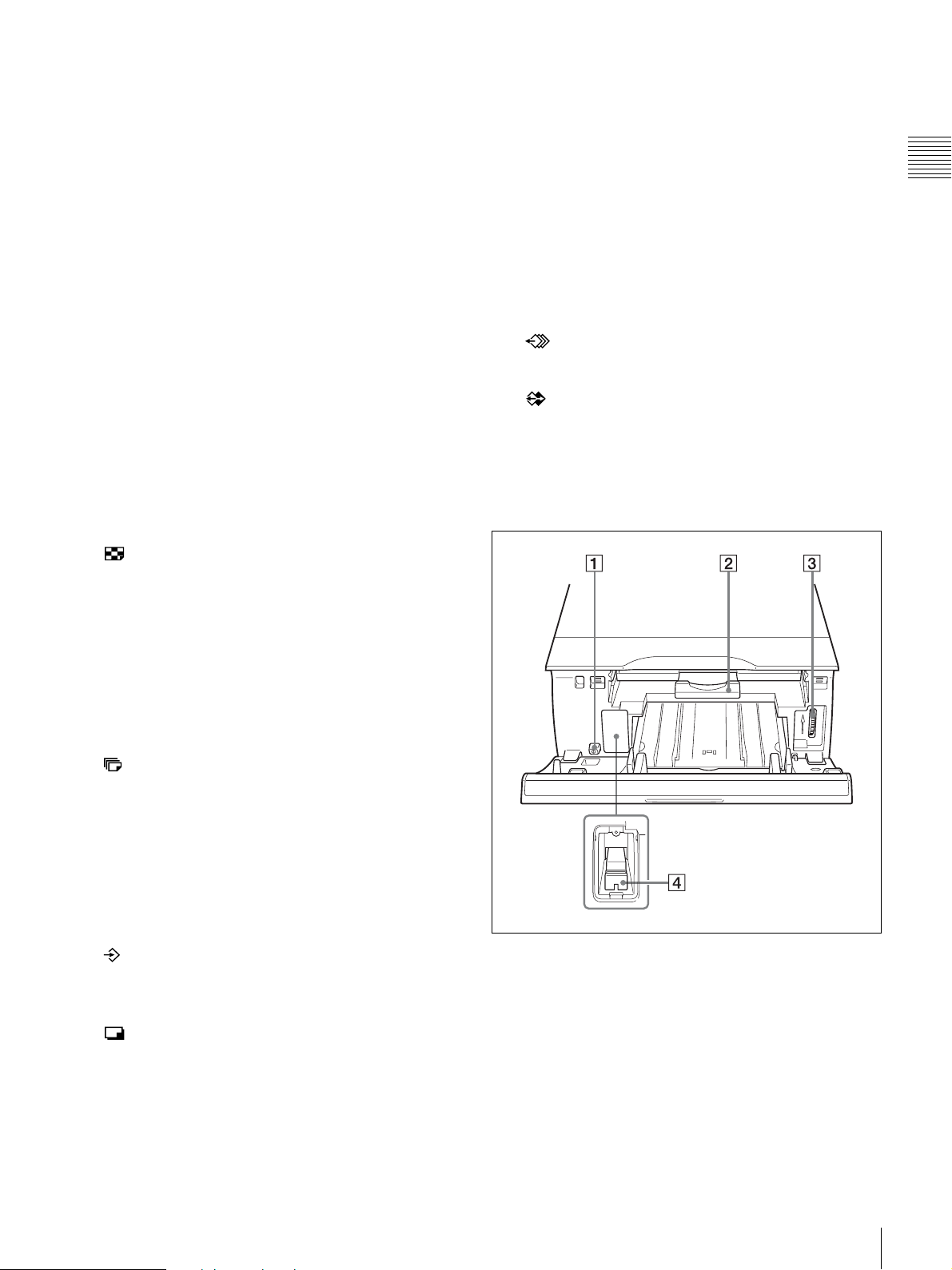
Inside the Ribbon Door Panel
J PRINT QTY button (page 24)
Press this button to select the number of copies to
print. You can select up to nine copies, and the current
selection is displayed for a few seconds when the
button is pressed. The PRINT QTY setting in the
PRINTER SETUP menu also changes in conjunction
with each press of this button.
You can press this button to change the number of
copies to print, even while printing is in progress.
K CAPTURE button
Press this button to capture images to memory for
printing.
L PRINT button
Press this button to print the images that are captured
to memory.
M ! POWER switch
Use this switch to turn the printer on or off.
A ! POWER switch
Use this switch to turn the printer on or off. This
switch functions even while the ribbon door panel is
open.
B Ribbon tray (page 15)
Load the ink ribbon in this tray.
C Dial (page 74)
Use this dial to clear paper manually when an internal
paper jam occurs.
Location and Function of Parts and Controls
9
D Media switch lever
Switch the position of this lever according to the type
of ink ribbon being used.
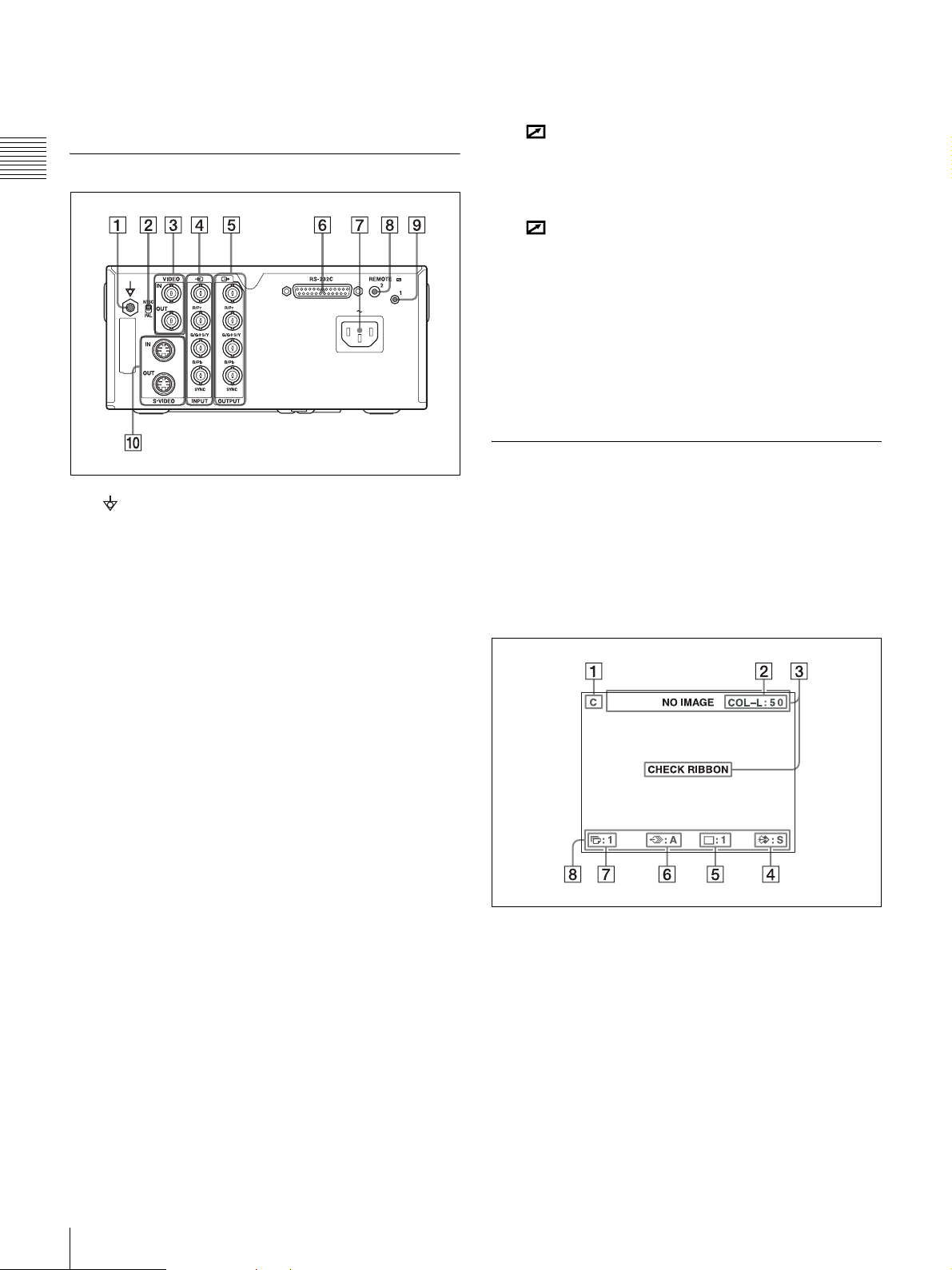
Rear
Introduction
A Equipotential ground terminal connector
Connects to a ground (equipotential) plug to bring the
various parts of the system to the same potential.
B NTSC/PAL switch
Switch the position as follows according to the video
signal being used.
When using NTSC video signals, set the switch to the
up position.
When using PAL video signals, set the switch to the
down position.
G - AC IN connector (page 12)
Connects to the power cord.
H REMOTE 2 connector (stereo mini jack)
(page 14)
Connects to an RM-91 Remote Control Unit (not
supplied) or an FS-24 Foot Switch (not supplied).
I REMOTE 1 connector (page 14)
Connects to an RM-5500 Remote Control Unit (not
supplied) for wired remote control.
J S-VIDEO IN/S-VIDEO OUT (S-Video input/S-
Video output) connectors
S-VIDEO IN connector: Connects to video
equipment with S-Video signal output connectors.
S-VIDEO OUT connector: Connects to video
equipment with S-Video signal input connectors.
Monitor Display
When the printer is connected to a video monitor and
turned on, the following screen is the first screen that
appears on the monitor. (This screen is referred to as the
“normal” screen in this document.)
When the MENU button is pressed, the menu screen is
displayed.
For detailed information on the menu screen, see “Menu
Tree” on page 41.
C VIDEO IN/VIDEO OUT (composite video signal
input/composite video signal output) connectors
(page 13)
VIDEO IN connector: Connects to video equipment
with composite video signal output connectors.
VIDEO OUT connector: Connects to video
equipment with composite video signal input
connectors.
D t INPUT (RGB/YPbPr/SYNC video signal
input) connectors (page 13)
Connects to video equipment with RGB/YPbPr signal
output connectors.
E T OUTPUT (RGB/YPbPr/SYNC video signal
output) connectors (page 12)
Connects to video equipment with RGB/YPbPr signal
input connectors.
F RS-232C connector (page 14)
Connects to a computer for controlling the printer.
A C (caption) display section
C is displayed when the printer is set to print a
caption.
B Ink ribbon type and remaining ink ribbon display
section
Displays the ink ribbon type and the remaining
amount of ribbon (indicates the number of printouts
that can still be made with the ribbon).
C Message display section
Usually messages are displayed on the top line of the
screen.
10
Location and Function of Parts and Controls
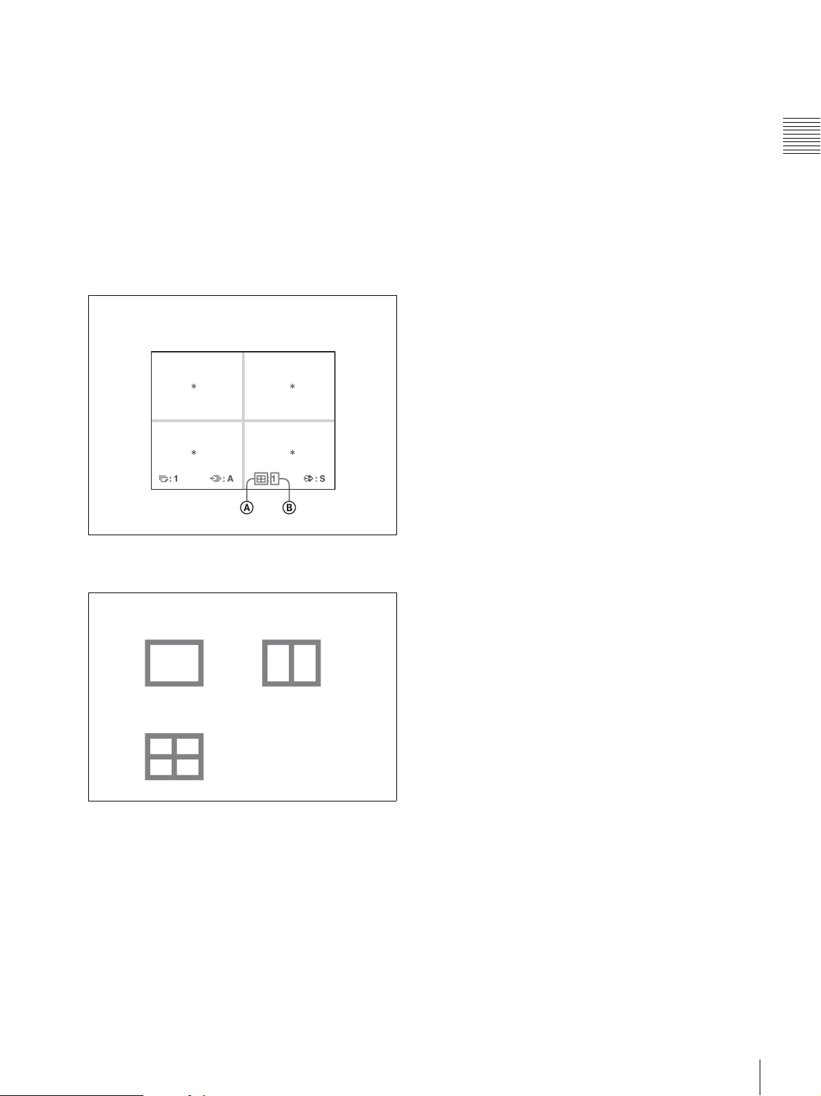
Urgent messages are displayed on the center of the
screen.
D S or M (image type) display section
Indicates the type of image being displayed on the
monitor.
S (Source): The image from the input signal source
is displayed on the screen.
M (Memory): The image captured in memory is
displayed on the screen.
E Printer operation mode display section
Indicates the printer operation mode (type of printouts
such as multiple reduced images).
Position of the cursor:
1st position of four reduced images
G Print quantity display section
Indicates the number of copies to be printed. This item
blinks while the printer is busy.
H Printer setting status display section
The currently selected status is displayed when either
MULTI PICTURE, PRINT QTY, or DISPLAY button
is pressed.
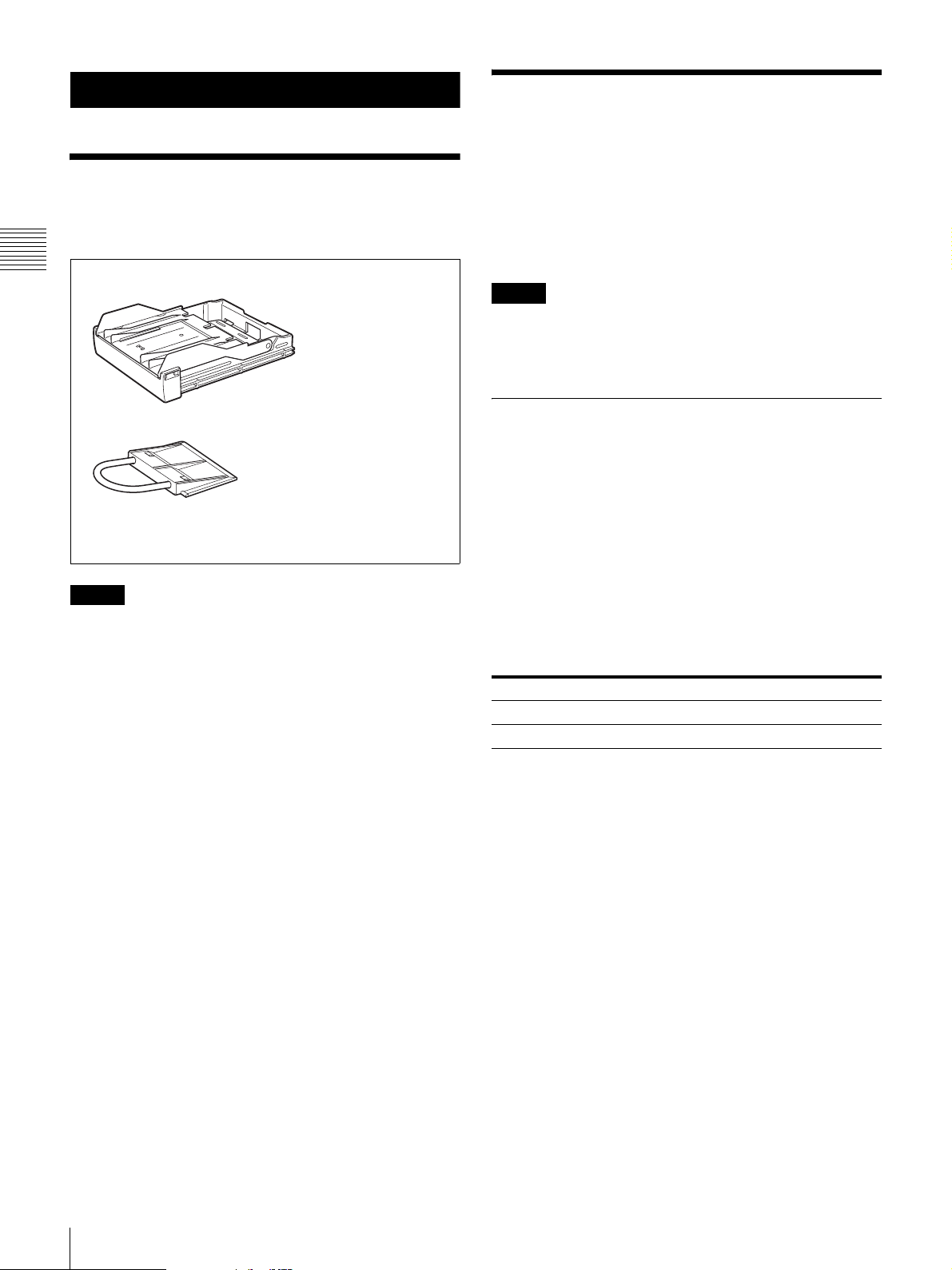
Introduction
A Type of printout
Indicates the type of printout.
Full-size image
Four reduced
images
Two reduced
images
B Position of the cursor
Indicates the position where the cursor is
currently placed and where an image will be
captured.
F Memory page display section
Indicates the currently selected memory page.
Memory pages that are currently being printed or
memory pages that are queued for printing will blink.
Location and Function of Parts and Controls
11
Preparation
Supplied Accessories
This printer is packed with the following accessories.
Check that nothing is missing from your package.
Preparation
Paper feed tray (1)
Connections
To enable printing, video equipment to act as an input
signal source, and a video monitor to display images or
menus must be connected.
The following diagrams illustrate how to make the input,
output and remote control connections. Use this as a guide
when connecting the cables required to transmit signals to
and from the equipment to be used for printing.
Notes
• Turn off the power of each device before attempting to
make any connections.
• Connect the AC power cord last.
Stopper (1)
Before Using This Printer (1)
Thermal head cleaning cartridge (1)
CD-ROM (Instructions for use) (1)
Notes
• Retain the original carton and packing materials in case
you have to transport this unit in the future.
• When transporting the printer, remove the ink ribbon and
paper feed tray, and lock the internal thermal head. For
details, see “Transportation” on page 64.
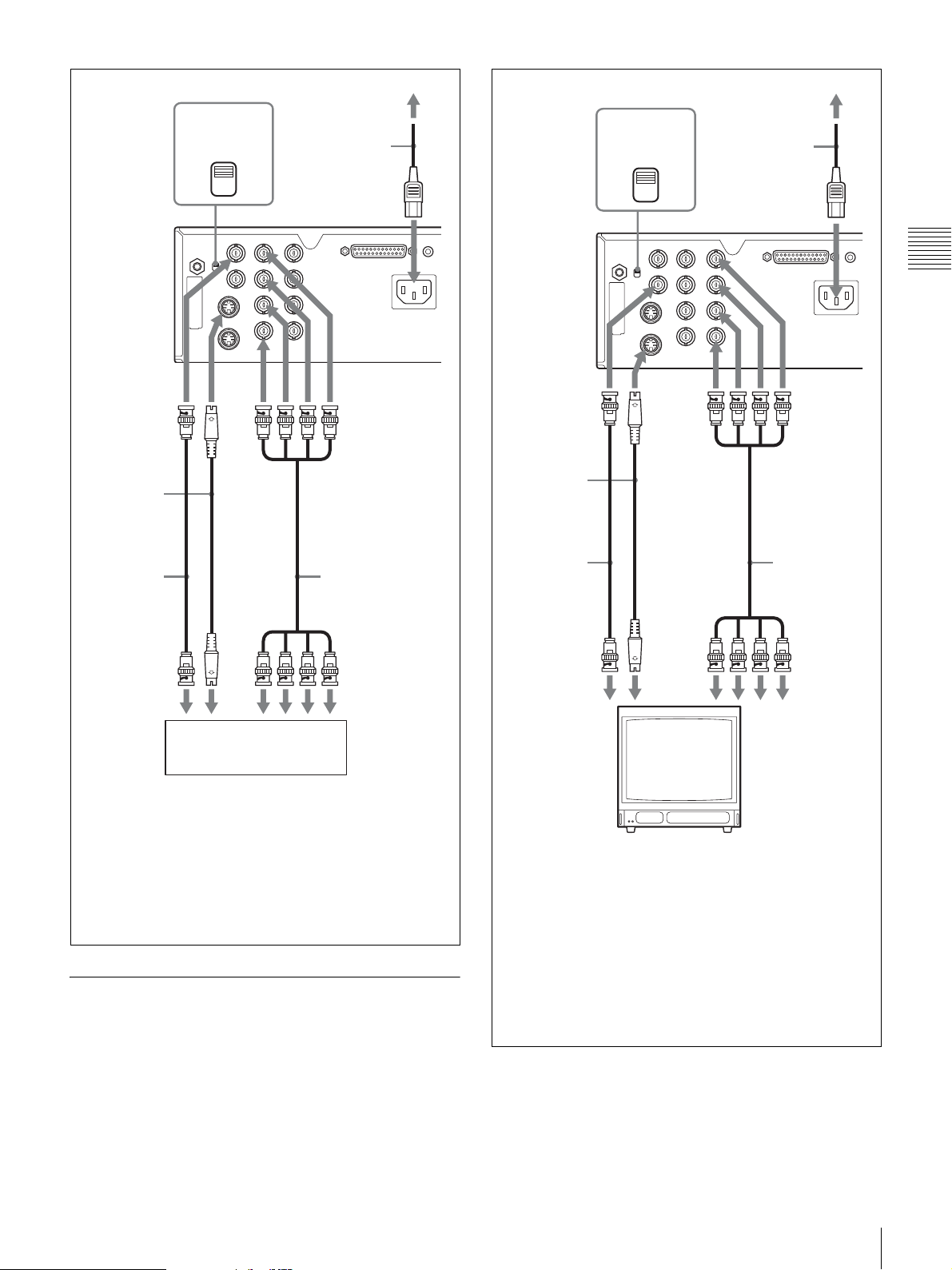
Connecting Video Equipment
Connect the video equipment providing the video images
to be printed.
Connect the video equipment which will be used in actual
printing, using the following diagram as a guide.
Connections for HDTV-signal input and output
Use the RGB/YPbPr/SYNC video signal input and output
connectors to connect equipment that will input and output
HDTV signals.
In addition, set the NTSC/PAL switch on the rear panel of
the printer as follows, based on the video system (NTSC/
PAL) you will use.
Video system Switch position
NTSC • Up
PAL • Down
Supported signals for the RGB/YPbPr/SYNC video signal
input and output connectors are as follows.
NTSC setting: 480/59.94i (SD), 1080/59.94i, 720/59.94p
PAL setting: 576/50i (SD), 1080/50i, 720/50p
12
Supplied Accessories / Connections
NTSC/PAL
a)
switch
to wall outlet
AC power cord
(not supplied)
NTSC/PAL
a)
switch
to wall outlet
AC power cord
(not supplied)
to VIDEO
INPUT
Connecting
cable (with
DIN 4-pin
connectors)
75-ohm
coaxial
cable with
BNC
connectors
to composite
video output
connector
to S VIDEO
INPUT
to S VIDEO
output
connector
to AC IN
to RGB/YPbPr/
SYNC INPUT
75-ohm
coaxial cable
with BNC
connectors
to RGB/YPbPr/
SYNC output
connectors
to AC IN
Preparation
b)
to VIDEO
OUTPUT
Connecting
cable (with
DIN 4-pin
connectors)
75-ohm
coaxial
cable with
BNC
connectors
to composite
video input
connector
to S VIDEO
OUTPUT
to S VIDEO input
connector
to RGB/
YPbPr/
SYNC
OUTPUT
75-ohm
coaxial cable
with BNC
connectors
to RGB/
YPbPr/SYNC
input
connectors
b)
c)
Video equipment
a) Set the switch to match your video signal system. Set the
switch to the upper position to set the video signal system to
NTSC. Set the switch to the lower position to set the video
signal system to PAL. To switch the video signal system, turn
the power off once, then change the setting. Then, turn the
power on again. If you change the setting with the power on,
this mode will not be switched.
b) When YPbPr signal is input, it is not necessary to connect to
the SYNC connector.
Connecting the Video Monitor
Connect a video monitor to view captured images and to
check those to be printed. Connect a suitable video monitor
which will be used in actual printing, using the following
diagram as a guide.
Video monitor
a) Set the switch to match your video signal system. Set the
switch to the upper position to set the video signal system to
NTSC. Set the switch to the lower position to set the video
signal system to PAL. To switch the video signal system, turn
the power off once, then change the setting. If you change the
setting with the power on, this mode will not be switched.
b) When connecting the video monitor only to the RGB/YPbPr/
SYNC OUTPUT connector without connecting to SYNC
connector, set OUTPUT SYNC in the OUTPUT SETUP menu
to ON.
c) When YPbPr signal is output, it is not necessary to connect to
the SYNC connector.
Connections
13
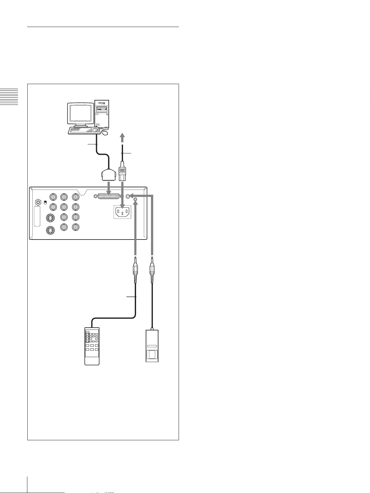
Making Connections to Enable Remote Control
The printer can be controlled remotely by connecting an
RM-5500 Remote Control Unit (not supplied), an RM-91
Remote Control Unit (not supplied), an FS-24 Foot Switch
(not supplied), or a personal computer.
a)
Computer
Preparation
RS-232C cable
to wall outlet
AC power cord
(not supplied)
to RS-232C
Remote control
connecting cable
(supplied with the
to REMOTE 1
RM-5500)
to AC IN
to
REMOTE 2
b)
RM-5500
(not supplied)
a) When connecting a personal computer, select the appropriate
baud rate from the SYSTEM SETUP menu. (See “Setting the
Baud Rate” on page 62.)
b) You can also use the remote control unit as a wireless unit. In
such a case, aim the head of the remote control unit at the
remote sensor on the printer. With fresh batteries, the range
of the remote control unit is about 3 meters.
14
Connections
RM-91
(not supplied)
FS-24
(not supplied)
Operation
Before Printing
Once the printer is connected to the computer (page 12),
you must load the paper and the ink ribbon as described
below before you can actually begin printing.
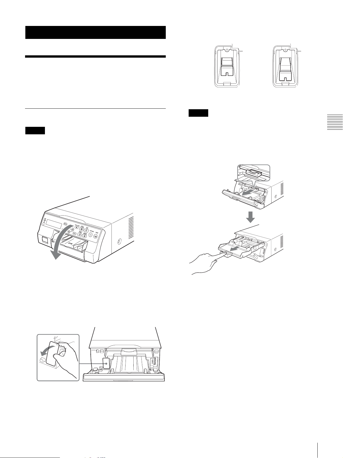
2 Switch the position of the media switch lever.
UPC-21S/UPC-21L: In UPC-24SA/UPC-24LA: Out
3 Replace the cover.
Loading the Ink Ribbon
Note
When using the printer for the first time, the thermal head
may be set to its transport position. Be sure to turn on the
printer and release the head from its transport position
before removing the ribbon tray.
Do not open the ribbon door panel if “PLEASE WAIT”
appears on the printer window display.
1
Open the ribbon door panel.
2
Switch the position of the media switch lever
according to the type of ink ribbon being used.
When using the printer for the first time or when
changing the type of ink ribbon to use, perform the
following to switch the position of the media switch
lever.
Note
Print quality may be adversely affected if the media
switch lever is not properly positioned. Make sure that
it is set either all the way in or all the way out,
depending on the ribbon type.
3
Pull the ribbon tray straight out of the printer.
Operation
1 Remove the cover.
Before Printing
15
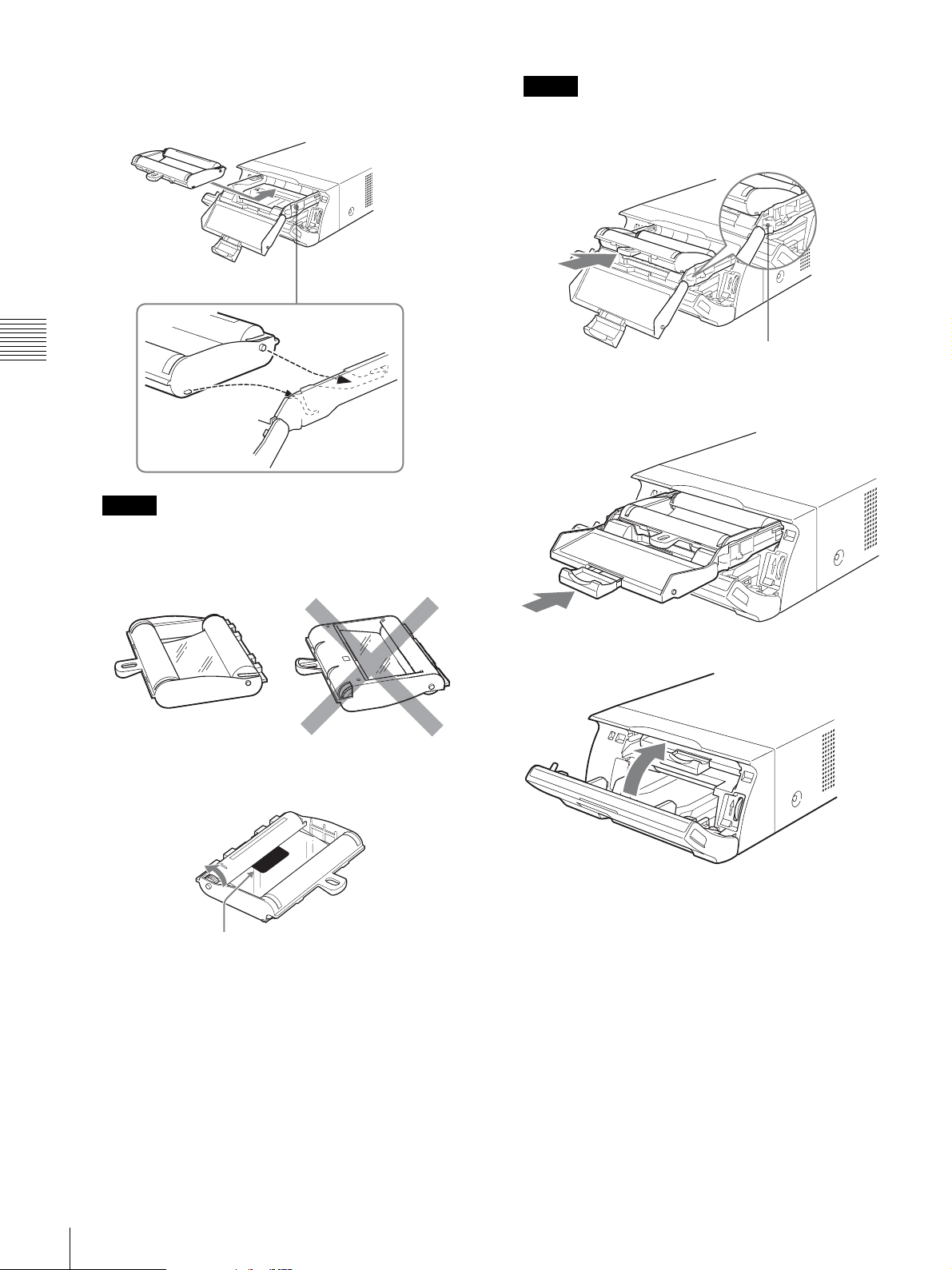
4
Load the ink ribbon.
1 Align the two pegs on each side of the ink ribbon
with the slots on the ribbon tray.
Note
Do not touch the white tabs on the sides of the ribbon
tray. Doing so may result in improper loading of the
ink ribbon.
Operation
5
Slide the ribbon tray straight into the printer until
completely inserted.
Notes
• Make sure to load the ink ribbon with the front and
back oriented correctly.
Right Wrong
6
Close the ribbon door panel.
• Before loading the ink ribbon, make sure to position
the start mark as shown below and remove any slack
by turning the gear in the direction of the arrow.
Ta b
16
Start mark
2 Slide the ink ribbon straight into the ribbon tray
until completely inserted.
Before Printing
To remove the ribbon tray
To remove the ribbon tray when replacing the ink ribbon,
for example, pull the tray straight out.
If the ink ribbon tears during use
Cellophane tape, etc., can be used to repair a torn ink
ribbon so that the remainder of the ribbon can be used.
Cellophane tape
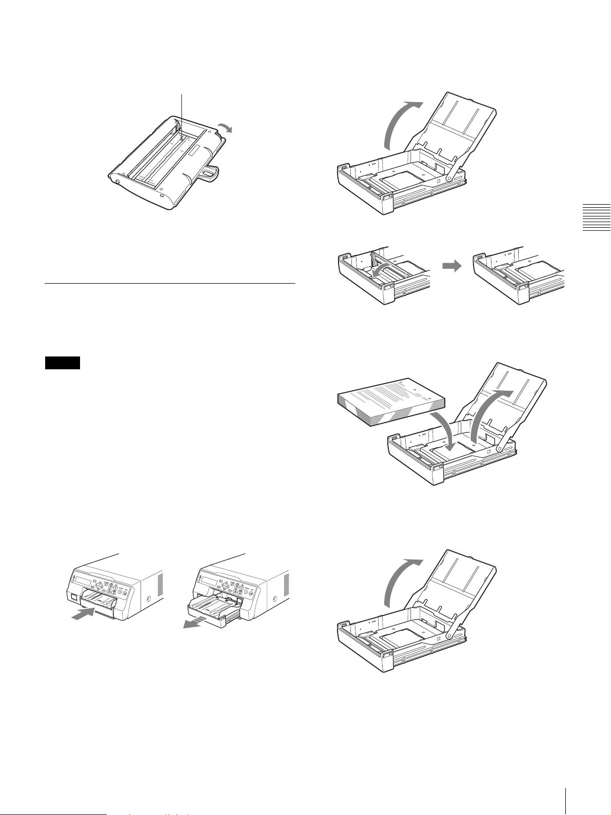
When using printing packs UPC-21L or
UPC-24LA
1 Open the paper feed tray.
Wind the ink ribbon until the cellophane tape is no longer
visible by turning the black (or gray) gear at the winding
end in the direction of the arrow. (Make sure the ink ribbon
does not sag.)
Loading the Paper
Follow the steps below to load paper into the paper feed
tray and to insert the tray into the printer.
When using the printer for the first time, begin with step 2.
Notes
• Be careful not to touch the print side of the paper.
• Use only the recommended paper for this printer. Other
types of paper may cause printer malfunctions, such as
paper jams. For details about compatible ink ribbons and
paper, see “Ink Ribbon and Paper” on page 66.
• When the message “CHANGE RIBBON” appears on
the printer window display, the ink ribbon is used up.
Replace the ribbon and load the printer with new paper.
• Be careful when inserting and removing the paper feed
tray, because it may cause the printer to shift position and
fall.
1
Press the Z mark on the paper feed tray to eject the
tray.
2 If the paper feed tray partition is raised, lower it.
3 Neatly stack and load the paper in the paper feed
tray, aligning the “v” mark on the protective sheet
with the “f” mark inside the tray.
When using printing packs UPC-21S or
UPC-24SA
1 Open the feed tray.
Operation
2
Open the lid of the paper feed tray, and load the paper
and protective sheet together with the print side facing
up.
Before Printing
17
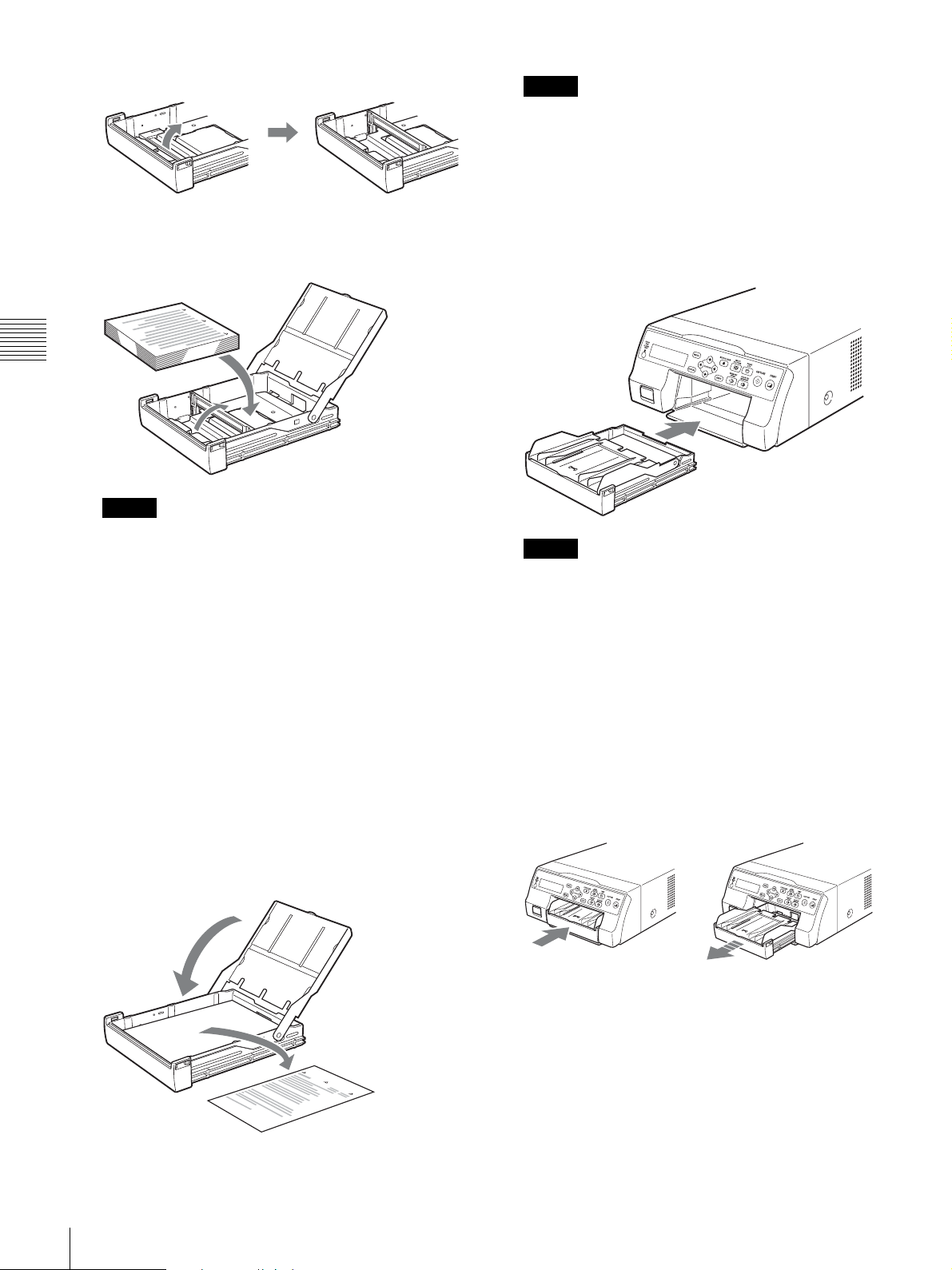
2 If the paper feed tray partition is lowered, raise it.
3 Neatly stack and load the paper in the paper feed
tray, aligning the “v” mark on the protective sheet
with the “f” mark inside the tray.
Operation
Notes
Note
Make sure to keep the protective sheet after removing
it. The reverse side of the protective sheet (without
printing), can be used as a cleaning sheet to clean the
thermal head. For details about cleaning, see
“Cleaning the thermal head and the internal rollers”
on page 65.
4
Insert the paper feed tray into the printer until it clicks
into place.
• When the paper runs out, do not just add more
paper. Replace both the paper and the ink ribbon.
Replenishing the paper midway may cause a paper
jam.
• When handling the paper, do not touch the print
side. Fingerprints and dust may adhere to the print
side and soil it. To prevent the print side from
becoming soiled, handle the paper with the
protective sheet (with printed warnings) attached.
• Load the paper properly so that it fits completely in
the paper feed tray. If the paper is bent, it will
protrude from the paper feed tray and may not feed
properly. Make sure to handle each ream of paper
by the protective sheet and to remove any bends in
the paper before using it.
• Do not put a mixture of different types of paper in
the paper feed tray.
3
Remove the protective sheet and close the lid.
Notes
• If the paper feed tray cannot be completely inserted
in the printer, check the tray insertion area and
remove any paper found there.
• Do not allow more than 10 printouts to accumulate.
Leaving too many printouts in the output tray could
cause a paper jam.
Attaching the Stopper
When multiple printouts are ejected, the printouts that
accumulate on the paper feed tray may fall out. To prevent
this, attach the stopper to the paper feed tray.
1
Press the Z mark area of the paper feed tray, and
remove the tray.
18
Before Printing
2
Fit the stopper into the two slits on the lid of the paper
feed tray, and insert it all the way in.
3
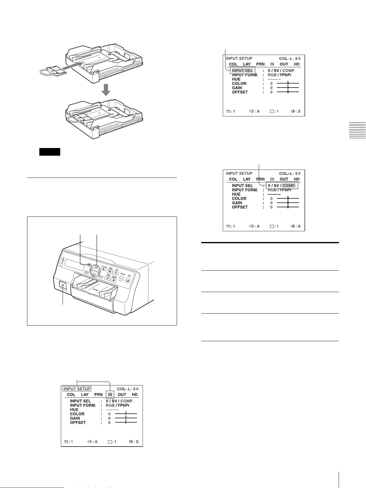
Select INPUT SEL by pressing the M or m button.
Highlight INPUT SEL in green by pressing
the M or m button.
4
Select the desired input signal by pressing the < or
, button.
Operation
Note
Do not pull on the metallic portion of the stopper.
Selecting the Input Signal
Before printing, select the appropriate input signal (the
input connector to which the signal to be printed is being
input) VIDEO, S VIDEO, or COMP.
2, 5 2, 3, 4, 5
1
1
Turn on the video monitor and the printer.
Highlight the desired input signal in green by
pressing the < or , button. The selected input
signal turns green and is spelled out.
Source signal of the
image to be printed
Signal from video equipment
connected to the VIDEO IN
connector
Signal from video equipment
connected to the S VIDEO
IN connector
Signal from video equipment
connected to the RGB/
YPbPr/SYNC INPUT
connectors
Video monitor and
printer window display
(the selected input
signal is spelled out)
V tVIDEO
SV t S-VIDEO
Ct COMP.
2
Press the MENU button and display the INPUT
SETUP menu by pressing the M, m, < or , button.
Highlight IN in green by pressing the M, m, < or ,
button, then the INPUT SETUP menu appears.
When you select COMP.
When you use the RGB/YPbPr INPUT connectors to
input the image data, select the appropriate type of the
input signal.
Before Printing
19
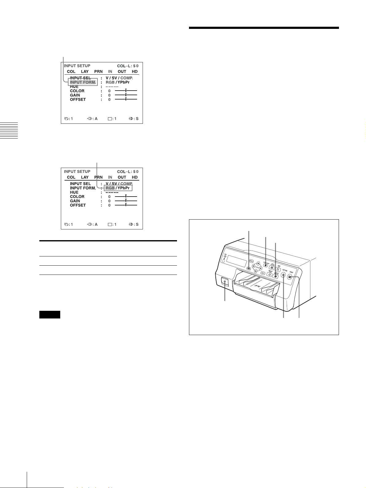
1 Select INPUT FORM. by pressing the M or m
button.
Highlight INPUT FORM. in green by
pressing the M or m button.
Operation
2 Select the type of the input signal by pressing the
< or , button.
Highlight the desired input signal in green
by pressing the < or , button.
Making Full-Size Image Printouts
This section explains how to make a full-size image
printout. The operations described here constitute the basic
procedure for making a printout.
Before making a full-size image printout
Make sure that the following preparations have been
performed, and refer to the reference pages as necessary.
Make sure to perform these preparations while the printer
is turned off.
• All connections should have already been made. (See
page 12.)
• Ensure that the appropriate ink ribbon/paper set is being
used and that they are correctly loaded. (See pages 15, 17
and 66.)
• Select the input signal to be used to make a printout. (See
page 19.)
• Set the printer to capture one full-size image into
memory. (See page 29.)
• Select the appropriate memory page. (See page 28.)
• Confirm the printout color quality (using, for example,
the LOAD COLOR number). (See page 46.)
Signal input to the RGB/YPbPr/
SYNC INPUT connectors
RGB input signal RGB
YPbPr input signal YPbPr
The format of the component signal output from the
RGB/YPbPr/SYNC OUTPUT connector depends on
the component signal selected here.
Note
The INPUT FORM. setting is enabled for SDTVsignal inputs and outputs. For details about HDTV
signals, see “Configuring HDTV-Signal Inputs and
Outputs” on page 57.
When using SDTV signals, set the SD/HD SEL
setting in the HDTV SETUP menu to SD or AUTO.
(See page 57)
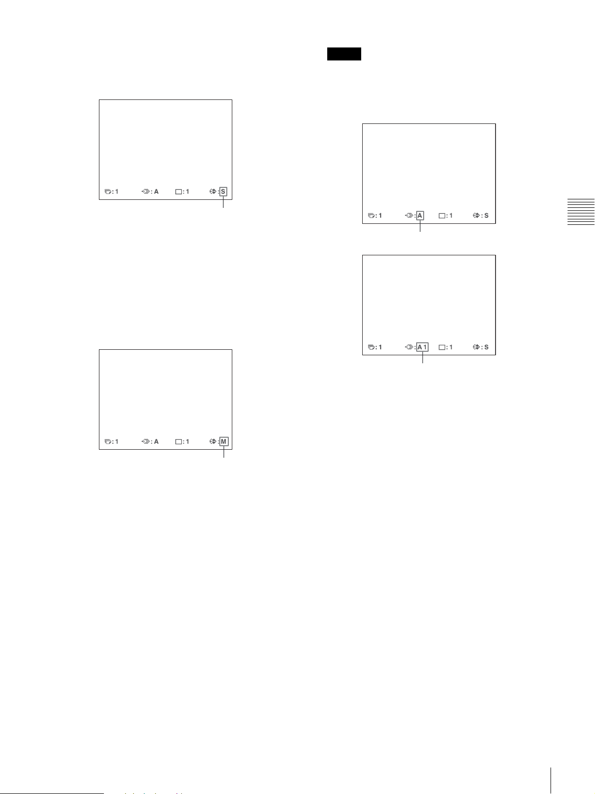
5
Press the MENU button.
The normal screen appears.
Select
DISPLAY button
STOP/CLEAR button
SOURCE MEMORY button
1
1
Turn on the video monitor and the printer.
3
4
20
Making Full-Size Image Printouts
2
Start the video source to display the source image on
the video monitor.
This operation is done using the controls of the video
equipment acting as the source.
Shows that an image from the source equipment is
currently displayed on the screen.
3
Press the CAPTURE button at the instant the image
you want to print appears on the screen.
The image is captured into memory. The memory
image is displayed on the screen. Which image
appears after this, the source image or the memory
image, depends on the setting made with the
FUNCTION SETUP facility of the printer. (See
page 30.)
Note
Usually, it is recommended that you make printouts in
FRAME mode. (The default setting is FRAME.)
You can confirm the memory mode setting on the
bottom part of the video monitor.
Operation
When FRAME mode is selected:
Shows that an image captured in memory is
displayed on the monitor.
If the captured image is blurred
A quickly moving image may be blurred when
captured. Should this occur, change the memory mode
setting to FIELD, then print it again. Although the
blur should be eliminated, the ultimate print quality
will be slightly degraded.
Select the FIELD mode on the LAYOUT SETUP
menu. (See “Selecting the memory mode” on
page 27.)
When FIELD mode is selected:
To change the image captured in memory
1 To display the source image when the memory
image is displayed on the screen, press the
SOURCE/MEMORY button.
2 Press the CAPTURE button at the instant the
image you want to print appears.
The previous image is replaced with the new one.
4
Press the PRINT button.
Making Full-Size Image Printouts
21
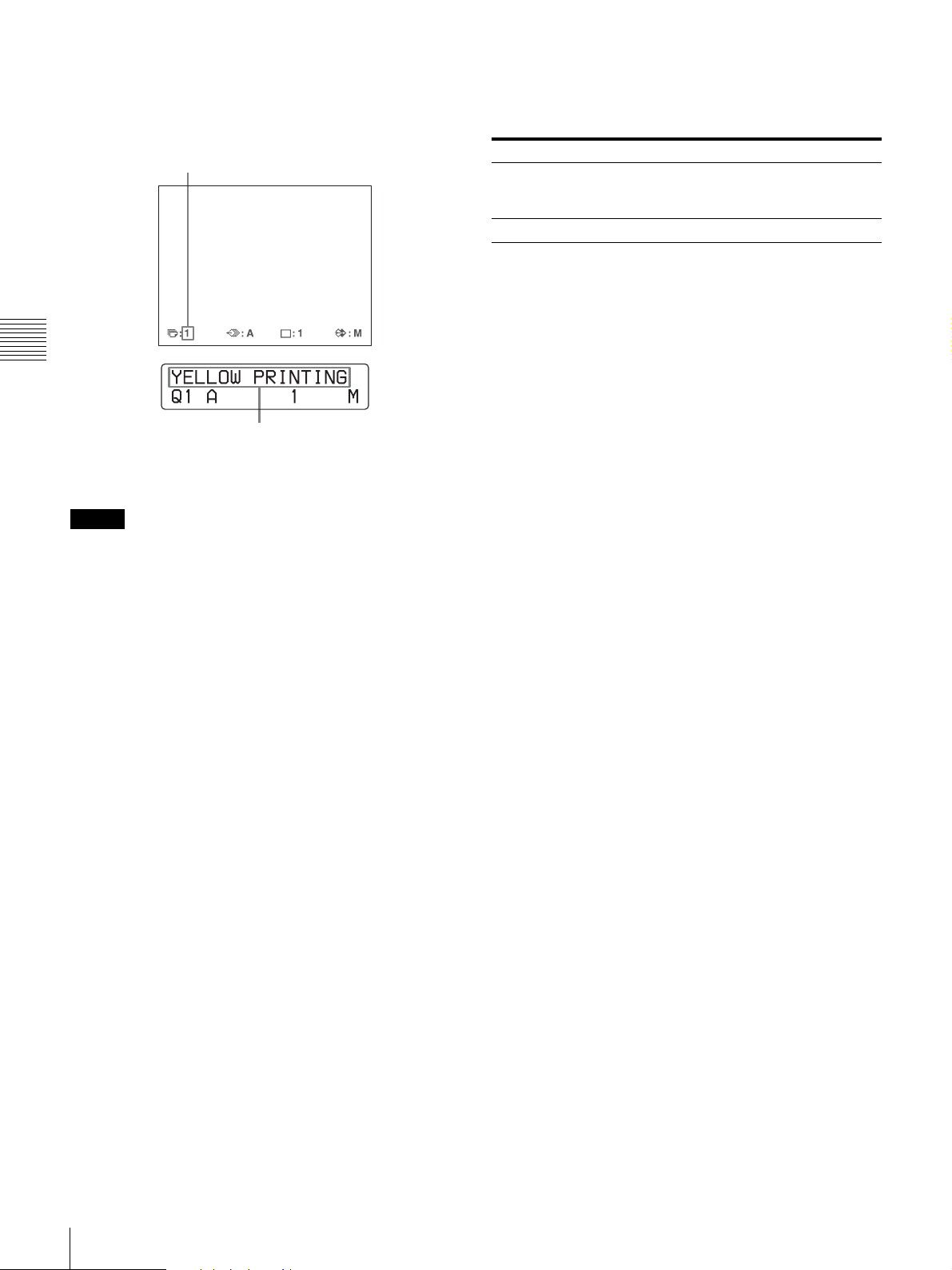
The printing time depends on the print speed settings.
On the video monitor, Q display blinks in the color which
is being printed.
The color changes as follows during printing:
Start t yellow t magenta t cyan t
white (laminate) t finish
Operation
On the printer window display, the color indication
changes as the color printing precedes:
Start t YELLOW t MAGENTA t CYAN t
WHITE (laminate) t finish
Notes
• Do not turn off the power during printing.
If you do so, paper may not be ejected and may jam in
the printer.
• Do not open the front door or not to remove the paper
tray during printing. Doing so may cause the paper
jamming because paper is not ejected correctly.
• Do not leave more than 10 sheets of printouts on the
paper tray. Doing so may cause a paper jam. Even if
fewer than 10 sheets of printouts have been accumulated
on the paper tray, the printer may stop printing for
various reasons and the message “REMOVE PRINTS”
appears. In such a case, remove printouts accumulated
on the paper tray. The printer will start to print
automatically.
• You can not change the printer application mode or
settings using the WINDOW SETUP menu during
printing.
To stop printing
• When you make one printout, you can not stop printing
midway. Wait until a printout pops out on the paper tray.
• When you make multiple copies, press the STOP/
CLEAR button. (For detailed information on setting the
print quantity, see “Making Multiple Copies of Identical
Printouts” on page 23.) The printer stops printing when
the page currently printing is completed. Also, any
printing job queued are cancelled.
If the printer does not print
While an error message is displayed on the video monitor
and printer window display.
Proceed as described in “Error/Warning Messages” on
page 71.
To change the printout speed
You can select the speed using the PRN SPEED item on
the PRINTER SETUP menu.
PRN SPEED When you want to
NORMAL Make a printout at normal speed.
You can create printouts with high-density
black.
HIGH Make a printout at high speed.
For detailed information on how to operate the menu, see
“Basic Menu Operations” on page 42.
When you want to see an image that is hidden
below a screen message
You can erase screen messages (such as Q1, A and so on)
from the video monitor by pressing the DISPLAY button.
The screen message disappears. To display a screen
message, press the DISPLAY button again. (See “Erasing
the Screen Display on the Video Monitor” on page 38.)
You can also erase the information about ink ribbon and
paper. (See “Displaying the Ink Ribbon Type and
Remaining Amount of the Ink Ribbon” on page 62.)
If a black line appears on the printout
Sometimes, a black line appears on the printout, although
it does not appear on the video monitor. This black line can
be eliminated from the printout. (See “When a Black
Frame or Lines Show up on the Printouts” on page 48.)
If the color quality of the printouts is not
satisfactory
You can obtain satisfactory color quality of the printouts
by compensating for the input signal and/or adjusting the
color quality of the printouts. (See “Compensating for the
Input Signals” on page 45, “Specifying Colors for
Adjustment (HSV Adjustment)” on page 52 and
“Adjusting the Printout Color” on page 46.)
When you load a new ink ribbon and paper, the color
balance may change due to differences caused by the new
pair of ink ribbon and paper in the new printing pack. It is
recommended that you adjust the color balance each time
you load a new ink ribbon and paper. (“Adjusting the Color
Balance” on page 50.)
When storing your printouts:
• Avoid storing the printout in a location subject to high
temperatures, high humidity, excessive dust or direct
sunlight.
• Do not stick tape on a printout. Also, avoid leaving a
plastic eraser on a printout or placing a printout in
contact with materials which contain plasticizer (under a
desk mat, for example).
• Do not allow alcohol or other volatile organic solvents to
come into contact with the printouts.
22
Making Full-Size Image Printouts
Making Printouts with the Desired User Set Number
You can register all the printer settings as a user settings.
The printer allows you to register three sets of settings as
User Set 1, 2 and 3. (See “Registering a User Set” on
page 62.) By selecting a desired user set number, the
printer functions according to the corresponding settings.
You can change a part of the selected user settings and
make printouts.
1 1, 2, 3
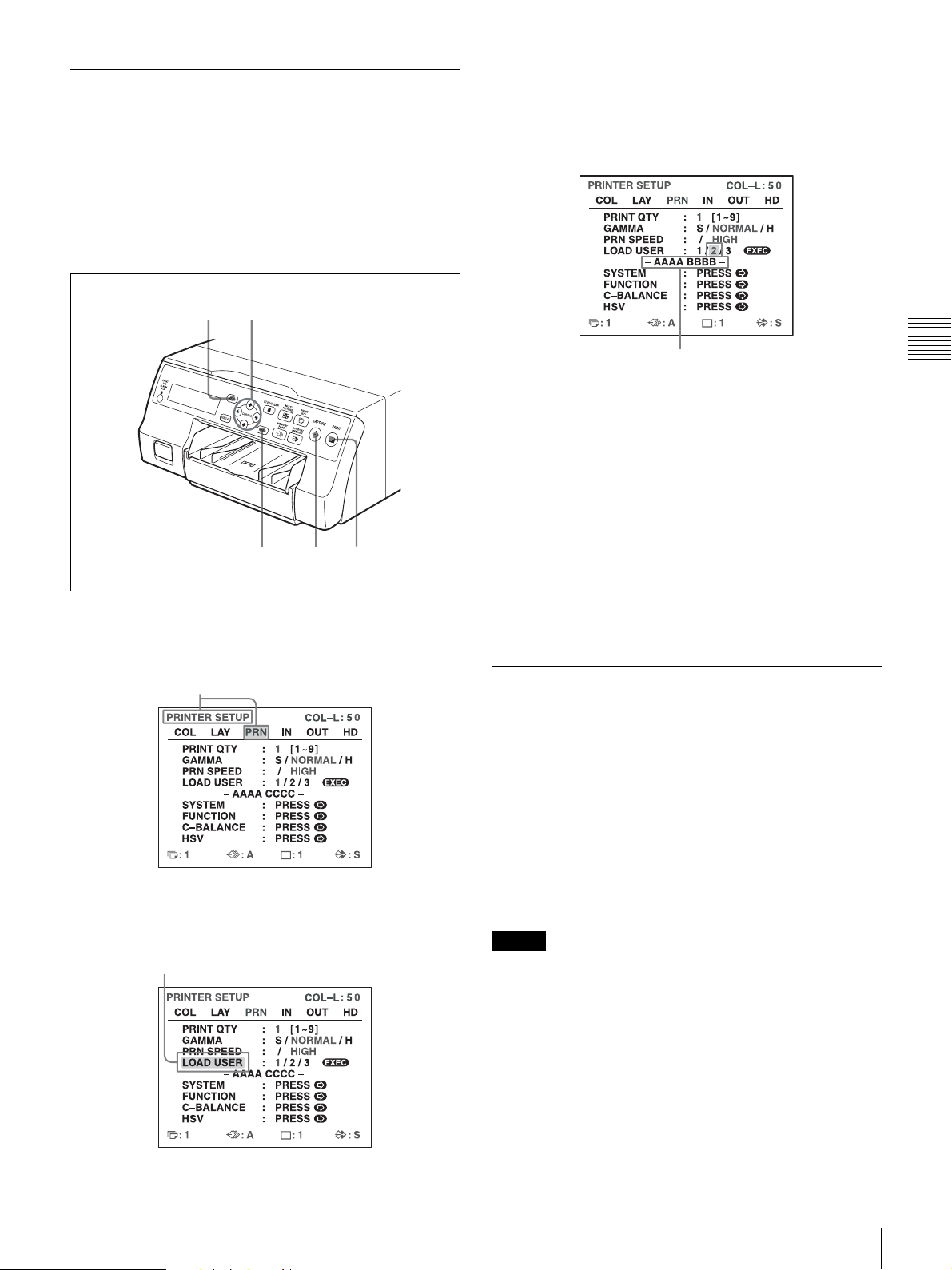
3
Select the desired user number by pressing the < or
, button.
Highlight the desired user number in green by
pressing the < or , button. The user name of
the selected user number appears below.
6
54
1
Press the MENU button, and display the PRINTER
SETUP menu by pressing the M, m, < or , button.
Highlight PRN in green by pressing the M, m, < or , button,
then the PRINTER SETUP menu appears.
2
Select LOAD USER by pressing the M or m button.
User name of the user set number
selected
4
Press the EXEC button.
The printer functions according to the settings
selected in step 3.
5
Press the CAPTURE button at the instant the image
you want to print appears on the screen.
The image is captured into memory according to the
user set selected in step 3.
6
Press the PRINT button.
The printer makes printouts according to the user set
selected in step 3.
Making Multiple Copies of Identical Printouts
You can make up to 9 copies of identical printouts.
Setting the printout quantity
The following two methods are available to set the number
of printouts.
• Using the PRINT QTY button
• Using the menu
You can change the designated number of copies before
printing or any time during printing.
Operation
Highlight LOAD USER in green by pressing the M
or m button. The currently selected load user
number is lit in green.
Note
When you change the designated number of copies during
printing, only the number of copies of printouts which are
being currently printed is changed. When printing is
completed, the number of copies is reset to the one set
before staring printing.
Making Full-Size Image Printouts
23

To set the printout quantity by using the PRINT
QTY button
21, 2
Operation
1
Press the PRINT QTY button.
The following screen appears.
If you do not perform any operation after you press
the PRINT QTY button, the currently set number of
copies appears for a few seconds, after which it
disappears.
To decrease the number of copies
While the screen which appears in step 1 is displayed,
press the < button. Each time you press the < button,
the number decreases. When the number reaches 1, if the
< button is pressed again, it goes up to 9.
Setting the printout quantity using the menu
1
Display the PRINTER SETUP menu according to the
operations of step 1 described in “Making Printouts
with the Desired User Set Number” on page 23.
2
Select PRINT QTY by pressing the M or m button.
Highlight PRINT QTY in green by pressing the M
or m button.
Currently selected number of copies
2
Press the PRINT QTY button until the desired number
appears, while the screen shown in step 1 is displayed.
Repeatedly pressing the PRINT QTY button increases
the number up to a maximum of 9. When the number
reaches 9, if the button is pressed again, it goes back
to 1. Or repeatedly pressing the , button also
increases the number up to a maximum of 9. When the
number reaches 9, if the , button is pressed again, it
goes back to 1.
3
Select the desired number of copies by pressing the
< or , button.
When you want to Button
Decrease the quantity. <
Increase the quantity. ,
Display the desired number of copies
by pressing the < or , button.
4
Press the MENU button.
The normal screen appears.
Note
Press the PRINT QTY button or , button until the
desired number appears.
24
Making Full-Size Image Printouts
Do not leave more than 10 sheets of printouts on the paper
tray. Doing so may cause a paper jam. Even if fewer than
10 sheets of printouts have been accumulated on the paper
tray, the printer may stop printing for various reasons and
the message “REMOVE PRINTS” appears. In such a case,
remove printouts accumulated on the paper tray. The
printer will start to print remaining copies automatically.

If the paper runs out during printing
The printer stops the printing operation.
Load the paper into the paper tray and press the PRINT
button.
However, the printout quantity is reset to the original
quantity requested before printing was stopped.
For example, if the printout quantity is set to 5, and the
paper runs out when three copies are printed, the printout
quantity is reset to 5. If you want to print only the
remaining copies, set the printout quantity to 2 after
loading the paper. (See “Loading the Paper” on page 17.)
3
Press the PRINT button.
The image captured in step 2 is queued. The image is
printed as soon as all previous printing jobs have been
completed.
Capturing Another Image While Printing
While the printer is printing, you can queue printing jobs
by capturing another image into another memory page to
be printed once the printer becomes free. The number of
usable memory pages depend on the type of printouts and
settings. (See “Memory page” on page 28.)
2
1
3
Memory page whose image has been queued for
printing (blinks on the video monitor)
The memory page display stop blinking and lights up on
the video monitor once printing has been completed.
Note
Another image cannot be stored in a memory page in
which an image has already been queued for printing
(memory page indication blinks). In such a case, the
“PLEASE WAIT PRINTING MEMORY” message
also appears.
4
To queue another memory page, repeat steps 1, 2 and
3.
Operation
1
Select the desired memory page by pressing the
MEMORY PAGE button.
Pressing the MEMORY PAGE button switches the
memory page.
The available memory pages do not blink.
2
Press the CAPTURE button at the instant the image
you want to print appears on the screen.
Making Full-Size Image Printouts
25

Making Variations of
Selecting the Memory Mode
Printouts
You can capture various kinds of images in memory and
make variations of printouts using the images captured in
memory.
Printout of a full-size
image
Operation
You can also make printouts of multiple reduced images
with white borders. (See “Making a printout with white
borders” on page 32.)
Captions can also be inserted in printouts. (See “Making
Printouts with a Caption” on page 33.)
Printing captions
The caption position on printouts of two reduced images
differs depending on whether SDTV signals or HDTV
signals are used. The caption position also differs
depending on the printing pack used.
Printout of two
reduced images
Printout of four
reduced images
Frame mode/field mode
To make printouts, it is first necessary to capture the image
in memory.
When capturing an image, there are two ways to use the
memory, one is called frame mode and the other is called
field mode.
Frame mode: An image is captured in a memory area.
Printouts with high resolution can be obtained.
Video monitor
The image
displayed on the
video monitor is
captured in
memory page A.
Printout
Printout of a full-size image Printout of four reduced images
xxxxxxxxxxxxxxxxxxxxxxxxxxxxxx
xxxxxxxxxxxxxxxxxxxxxxxxxxxxxx
Printout of two reduced
images (SDTV signal)
Printout of two reduced images
(HDTV signal, UPC-21S/UPC-24SA)
Printout of two reduced images
(HDTV signal, UPC-21L/
UPC-24LA)
xxxxxxxxxxxxxxxxx
xxxxxxxxxxxxxxxxx
A still subject can be printed
with high resolution.
26
Making Variations of Printouts

Field mode: A memory area is divided into two, and
images can be captured in each. In this way a quickly
moving subject can be printed with less blurring.
Video monitor
The image
displayed on the
video monitor is
captured in
memory page A1.
Printout
1
Press the MENU button and display the LAYOUT
SETUP menu by pressing the < or , button.
Highlight LAY in green by pressing the < or ,
button, then the LAYOUT SETUP menu appears.
2
Select MEMORY by pressing the M or m button.
Highlight MEMORY in green by pressing the M or m
button.
Operation
A quickly moving subject can
be printed with less blurring.
Selecting the memory mode
1, 4 1, 2, 3
3
Select the desired memory mode by pressing the <
or , button.
Highlight the desired memory mode in green by
pressing the < or , button.
Mode Contents
FRAME We recommend that, whenever possible,
FIELD Select this mode to reduce blurring when
Note
you print in this mode.
you print a quickly moving image.
If the input signal type is 720p, the memory mode is
fixed at FRAME mode. “- - - - -” appears for the
MEMORY setting in the LAYOUT SETUP menu,
and FIELD mode is not available.
Making Variations of Printouts
27

4
Press the MENU button.
The normal screen appears.
Selecting a Memory Page
Memory page
A memory area in which an image is captured is called a
memory page in this manual.
The number of usable memory pages depends on the type
of the reduced images selected and on the memory mode.
Usable memory page Type of reduced
a)
FRAME FIELD
Operation
A, B, C, D, E,
F, G, H
A, B, C, D A1, A2, B1, B2, C1,
A, B A1, A2, B1, B2 Four reduced images
a) Cannot be selected when the input signal type is 720p.
A1, A2, B1, B2, C1,
C2, D1, D2, E1, E2,
F1, F2, G1, G2, H1,
H2
C2, D1, D2
images to be captured
in memory
Full image
Two reduced images
Press the MEMORY PAGE button repeatedly until the
desired memory page appears.
Currently selected memory page
Note
Images of differing signal types (SDTV/1080i/720p)
cannot coexist on the same multiple reduced image screen.
If you change the input signal type with the SD/HD SEL
setting in the HDTV SETUP menu, the images stored in
the memory will be overwritten the next time you capture
images.
Selecting a memory page
MEMORY PAGE button
28
Making Variations of Printouts

Making a Printout of Multiple Different Reduced Images
You can capture multiple images in a memory page and
make a printout with those reduced images. This section
explains how to make a printout with multiple reduced
images.
A printout having multiple reduced images is made using
the procedure below.
• Determining the number of reduced images (See below.)
• Selecting the memory page (See page 28.)
Selecting the number of reduced images to
be captured in memory
The following two methods are available to select the
number of reduced images:
• Using the MULTI PICTURE button
• Using the menu
To select the desired type of reduced images to
be captured in memory using the MULTI PICTURE
button
1, 2
The currently selected type of reduced
images to be captured in memory is lit
in green.
2
Select the type of reduced images to be captured in
memory by pressing the MULTI PICTURE button,
while the screen which appears in step 1 is displayed.
Press the MULTI PICTURE button repeatedly until
the color of the type of reduced images to be captured
in memory turns green on the video monitor, or until
the type of reduced images to be captured in the
memory is displayed on the printer window display.
Each time you press the MULTI PICTURE button, the
type of reduced-image printout changes in the
following sequence: 1, 2, 4, 1....
Type Number of reduced images
1 1 (Full-size image)
2 2 (Two reduced images)
4 4 (Four reduced images)
Operation
1
Press the MULTI PICTURE button.
The following screen appears. If you do not perform
any operation after you press the MULTI PICTURE
button, the current setting appears for a few seconds,
after which it disappears.
The screen is reset to the normal screen after a few
seconds.
To select the type of reduced images to be
captured in the memory using the menu
1
Display the LAYOUT SETUP menu according to the
operations of step 1 described in “Selecting the
memory mode” on page 27.
2
Select MULTI PIX by pressing the M or m button.
Highlight MULTI PIX in green by pressing the M or m
button.
Making a Printout of Multiple Different Reduced Images
29

3
Select the type of reduced images to be captured in
memory by pressing the < or , button.
Highlight the type of reduced images to be captured
in memory in green by pressing the < or , button.
Operation
4
Press the MENU button.
The normal screen appears.
Deciding which image is displayed on the
video monitor after capturing an image
You can switch image displayed on the video monitor after
capturing an image, a memory image or a source image.
6 2, 3, 4, 5
The FUNCTION SETUP menu appears.
4
Select AUTO LIVE by pressing the M or m button.
Highlight AUTO LIVE in green by pressing the M or m
button.
5
Select which image appears on the video monitor after
the image is captured, by pressing the < or ,
button.
When Setting
The image captured in memory appears
just after the printer captures the image,
and the memory image remains on the
video monitor.
The image captured in memory appears
just after the printer captures the image,
then after a few seconds, the source
memory appears, whenever you press the
CAPTURE button.
OFF
ON
1
Display the PRINTER SETUP menu according to the
operations of step 1 described in “Making Printouts
with the Desired User Set Number” on page 23.
2
Select FUNCTION by pressing the M or m button.
Highlight FUNCTION in green by pressing the M or m
button.
6
Press the MENU button.
The normal screen appears.
To return to the PRINTER SETUP menu
In step 6, position the cursor at PRN SETUP and press the
, button.
The PRINTER SETUP menu appears again.
Making a printout with multiple reduced
images
This subsection explains how to make printouts of multiple
reduced images taking, as an example, the making of a
printout of four reduced images.
Before making the printout of four reduced
images
• Confirm the printout color quality (using, for example,
the LOAD COLOR number). (See page 46.)
• Set the layout to four reduced images. (See page 29.)
• Select the appropriate memory page. (See page 28.)
• Select which image will appear after the image has been
captured into memory, the memory image or the source
image. (See page 30.)
3
Press the , button.
30
Making a Printout of Multiple Different Reduced Images

• Select whether the white borders are to be added. (See
page 32.)
The white border setting for printouts of four reduced
images can be made before or after the four images are
captured to memory.
2
M, m, <, , buttons
5
display in step 1. The green blinking star (referred to
as the cursor) on the video monitor moves to the next
position and the number on the printer window
display advances by 1.
The blinking cursor moves to the next position.
3
1
Output images from the video device (source images)
onto the monitor.
This operation is done using the controls of the video
equipment acting as the source.
In the mode where white borders are to be
attached around the images, the white borders
appears on the screen.
The memory
page in which
Blinks in green to
indicate that an
image will be
captured here.
the four reduced
images are to be
captured.
The number advances by 1.
At this time, the image captured in memory is
displayed on the video monitor. However, the image
to be displayed after a few seconds depends on the
setting of AUTO LIVE in the FUNCTION SETUP
menu. (See page 30.)
When the image captured in memory is kept being
displayed, go to step 3.
When the source image is displayed, go to step 4.
3
Press the SOURCE/MEMORY button.
The source image appears on the video monitor.
4
Repeat steps 2 and 3 until you have captured four
images when the memory image remains on the video
monitor.
Repeat step 2 until you have captured four images
when the source image appears on the video monitor.
To replace a captured image
Example: When you want to change the image
captured in the third position.
1 Select the third position where the image which
you want to replace is located by pressing the M,
m, < or , button.
Operation
Indicates that an image will
be captured here.
Type of multiple reduced images
to be captured
2
Press the CAPTURE button at the instant the image
Indicates that the images
from a piece of video
equipment are displayed
on the screen.
you want to print appears on the screen.
The image is captured in the location indicated by the
green blinking star on the video monitor or the
position number displayed on the printer window
Making a Printout of Multiple Different Reduced Images
31

Pressing the M, m, < or , button moves the
cursor one position by one position vertically or
horizontally.
Press the M, m, < or , button until the third cursor
blinks green.
Note
This setting is also effective for the images which have
been captured.
1
Display the LAYOUT SETUP menu according to the
operations of step 1 described in “Selecting the
memory mode” on page 27.
2
Select SEPARATE by pressing the M or m button.
Highlight SEPARATE in green by pressing the M or m
button.
Operation
Press the M, m, < or , button until a 3 appears.
2 Display the source image on the video monitor.
For detailed information on how to display the
source image, see step 3.
3 Press the CAPTURE button at the instant the
image you want to print appears.
The previously captured image is replaced with
the newly captured image.
To keep a previously captured image
Skip images that you want to keep by pressing the M,
m, < or , button.
5
Press the PRINT button.
The four reduced images are printed on one sheet of
paper.
Whether white borders are attached depends on the
setting of SEPARATE in the LAYOUT SETUP menu.
(See page 32.)
If the printout is blurred
When you make a printout of a full image, or two or four
reduced images captured in memory in FRAME mode, the
images on a printout may be blurred. Should this occur,
change the memory mode setting to FIELD on LAYOUT
SETUP menu (“Selecting the memory mode” on page 27),
then print it again. Although the blur should be eliminated,
the ultimate print quality will be slightly degraded.
3
Select whether the images are printed with or without
white borders by pressing the < or , button.
Switch the desired setting to green by
pressing the < or , button.
When you want to Setting
Print the images without white borders. OFF
Print the images with white borders. ON
a) F is attached to the type of printout at the printer operation
mode display section in the printer window display.
Example: 4F
a)
Note
Usually, it is recommended that you make printouts in
FRAME mode. Check the setting on the LAYOUT SET
UP menu.
Making a printout with white borders
The unit allows you to decide whether or not the images
are printed with white borders.
32
Making a Printout of Multiple Different Reduced Images
4
Press the MENU button.
The normal screen appears.

Non-text caption entry operations
Making Printouts with a Caption
Making Printouts With a Caption
A caption, such as comments, can be added to a printout
below the image.
You can input up to 58 characters on one line.
About the CAPTION menu
A caption is entered from the CAPTION menu.
A brief explanation of each item of the CAPTION menu is
given below.
Non-text caption entry operations.
Character entry area
The character or symbol where the
cursor is located is highlighted in
green and this highlighted character
is to be entered.
Character display area
The cursor lit in green indicates
the position where a character
can be entered. The entered
characters are displayed here.
Display in the
CAPTION menu
INS Inserts one character without erasing the
DEL Deletes a highlighted character and characters
SP Puts one space at the position of the
OFF Selects printing without a caption.
ON Selects printing with a caption.
EXIT Returns from the CAPTION menu to the
SHIFT Selects either capital letters or small letters.
Function
highlighted character.
shift back by one.
highlighted character by erasing that
character. One space is left.
LAYOUT SETUP menu.
Entering a Caption
Enter a caption as follows.
The setting remains effective until you enter a new setting
– even if you turn the power off.
10 2, 3, 4, 5, 8, 9
Operation
Video monitor
Indicates the character selected in the
character entry area.
ON: displayed when printing
with a caption.
OFF: displayed when printing
without a caption.
Indicates the position where the
character is to be input in the
character display area.
4, 6, 8, 9
1
Display the LAYOUT SETUP menu according to the
operations of step 1 described in “Selecting the
memory mode” on page 27.
Making Printouts with a Caption
33

2
Select CAPTION by pressing the M or m button.
Highlight CAPTION in green by pressing the
M or m button.
5
Select the character you want to enter by pressing the
M, m, < or , button.
Example: Enter S.
Highlight S in green by pressing the M, m, < or ,
button. S blinks in green.
3
Press the , button.
Operation
The CAPTION menu appears.
4
Position the cursor (the line lit in green) at the point
where you want to enter the character in the character
display area.
To move the cursor
1 Select the arrow corresponding to the direction in
which you want to move the green cursor in the
character display area, by pressing the M, m, <
or , button.
2 Press the EXEC button.
Each time you press the EXEC button, the cursor
moves one position in the designated direction.
Example: Move the cursor to the left by two.
1 Highlight the <
button in green.
The cursor is currently
positioned here (lit in green).
When you enter characters on the printer
window display:
It is recommended that you display the characters to
be entered on the printer window display by pressing
either < or , button.
When the cursor is positioned at the right
end:
The cursor moves to the left end on the next line when
you press the , button.
For example, when the cursor is positioned at N,
pressing the , button results in the cursor moving to
O at the left end on the next line.
To select either capital letters or small letters
You can change the characters in the character entry
area from capital letters to small letters or vice versa.
1 Highlight SHIFT in green by pressing the M, m,
< or , button on the video monitor. Or display
SHIFT or shift on the printer window display.
When characters are displayed in capital letters in
the character entry area, shift is displayed in the
printer window display. When displayed in small
letters, SHIFT is displayed.
The blinking cursor moves
to this position.
34
Making Printouts with a Caption
2 Press the EXEC
button twice.
2 Press the EXEC button.
Capital letters are changed to small letters, or
small letters are changed to capital letters in the
character entry area.
Note
Characters already entered (displayed in the character
display area) are not changed even if letters are
changed in the character entry area.

6
Press the EXEC button.
The character selected in step 5 appears at the point
where the green cursor is positioned in the character
display area, after which the cursor moves to the next
position.
The cursor moves to this position.
To replace a previously entered character
without changing the number of characters
You can replace a previously entered character with a
new one.
1 Position the green cursor at the character to be
replaced by performing the operations explained
in step 4.
2 Overwrite the invalid character with the correct
character by performing the operations explained
in steps 5 and 6.
The previously entered character is replaced with
the new one.
When you enter the wrong character in the
above example
1 Select by pressing the M, m, < or , button,
then press the EXEC button.
The cursor moves back by one and the character
entered in step 5 is highlighted in green.
2 Select DEL by pressing the M, m, < or ,
button.
Lit in green
Highlight DEL in green by pressing the M, m,
< or , button. DEL blinks in green.
To add characters midway
Operation
1 Position the cursor at the position where a
character is to be added by performing the
operations explained in step 4.
2 Select INS by pressing the M, m, < or ,
button. Then press the EXEC button.
A single space is inserted between characters and
the cursor is positioned at the space.
3 Enter the character to be added.
When it is necessary to change the CAPTION
ON/OFF setting, go to step 8. If not, go to step 9.
Example: Add a character between A and B.
1 Move the cursor to B. (B is highlighted in green.)
2 Highlight INS. (INS blinks in green).
Then, press the EXEC button.
3
Press the EXEC button.
The character selected in 1 is deleted.
When the character to be deleted is located among
previously entered characters, the characters after
the deleted one shift back by one.
7
Repeat steps 4, 5 and 6 to enter the remaining
characters of the caption.
To enter a space
1 Position the green cursor at the point where you
want to enter a space.
2 Select SP by pressing the M, m, < or , button.
3 Press the EXEC button.
A single space is entered and the green cursor
moves to the next position.
A single space is inserted between A and B and
the green cursor is positioned at the space.
Cursor (lit in green)
Making Printouts with a Caption
35

8
Set the CAPTION ON/OFF function to ON.
1 Select ON by pressing the M, m, < or , button.
Deleting Images Stored in Memory
You can use the STOP/CLEAR button to delete individual
reduced images captured to a memory page, or to delete all
of the images from one or all of the memory pages.
Whether the images of all memory pages or only a single
memory page are deleted depends on the setting of
CLEAR in the FUNCTION SETUP menu.
As the STOP/CLEAR button functions as the STOP button
Highlight ON by pressing the M, m, < or , button.
ON blinks in green.
Operation
Select OFF to make printouts without a caption.
2 Press the EXEC button.
The display changes from OFF to ON.
when printing is in progress, images cannot be deleted
while printing is in progress.
Setting the Function of the STOP/ CLEAR Button
1
Display the FUNCTION SETUP menu according to
the operations of steps 1 to 3 described in “Deciding
which image is displayed on the video monitor after
capturing an image” on page 30.
2
Select CLEAR by pressing the M or m button.
9
After entering the caption, highlight EXIT by
pressing the M, m, < or , button, then press the
EXEC button.
The LAYOUT SETUP menu appears.
10
Press the MENU button.
Note
Characters entered in steps 4 to 7 are stored after
completing the operation of step 7. These characters
remain even after you turn off the printer.
Highlight CLEAR in green by pressing the M or m
button.
3
Select the function of the STOP/CLEAR button by
pressing the < or , button.
Highlight the desired function in green
by pressing the < or , button.
36
Deleting Images Stored in Memory

When you want to Settings
Delete images of all memory pages. ALL
Delete images of a single memory page. PAGE
Delete the reduced image. PART
Disable functioning as the CLEAR
button.
4
Select PRN SETUP by pressing the M or m button.
Then, press the , button.
The PRINTER SETUP menu appears.
Once you set the function of the STOP/CLEAR
button, the STOP/CLEAR button functions according
to the setting until the function setting is changed.
To return to the normal screen
Press the MENU button.
OFF
Deleting images in a certain memory page
Before deleting images
Set CLEAR to PAGE in the FUNCTION SETUP menu.
2
3
1
Operation
Deleting Images Stored in Memory
Note
You cannot restore images once they have been deleted.
Deleting images in all memory pages
simultaneously
Before deleting images in all memory pages
Set CLEAR to ALL in the FUNCTION SETUP menu.
STOP/CLEAR button
1
Press the SOURCE/MEMORY button when the
source image is displayed on the video monitor.
The image captured in memory is displayed on the
screen.
2
Select the memory page from which images are to be
deleted by pressing the MEMORY PAGE button.
3
Press the STOP/CLEAR button.
The images in the memory page selected in step 2 is
deleted.
Deleting a certain reduced image
Before deleting images
Set CLEAR to PART in the FUNCTION SETUP menu.
2
3
1
Press the STOP/CLEAR button.
All images captured in the printer are cleared.
Notes
• Even if you press the STOP/CLEAR button when the
source image is displayed on the video monitor, the
memory image appears without deleting images in the
memory pages. In this case, press the STOP/CLEAR
button again. All images stored in the printer are cleared.
• An image which is being printed cannot be cleared.
4
Deleting Images Stored in Memory
37

1
Press the SOURCE/MEMORY button when the
source image is displayed on the video monitor.
The image captured in memory is displayed on the
screen.
2
Select the memory page from which the reduced
image is to be deleted by pressing the MEMORY
PAGE button.
3
Select the reduced image that you want to delete by
pressing the M, m, < or , button.
Make the cursor at the reduced image
to be deleted blink in green.
Operation
Erasing the Screen Display on the Video Monitor
You can erase characters displayed on the video monitor
(Q1, A and so on) when, for example, it is hard to see the
image that is hidden behind the screen display. The printer
operation is the same, regardless of whether those
characters are displayed on the video monitor. Since the
same characters are displayed in the printer window
display, perform operations watching them in the printer
window display.
For detailed information on displaying the ink ribbon type
and the remaining amount of the ink ribbon, see
“Displaying the Ink Ribbon Type and Remaining Amount
of the Ink Ribbon” on page 62.
1, 2
4
Press the STOP/CLEAR button.
The reduced image selected in step 3 is deleted.
1
Press the DISPLAY button.
The current setting appears. The video monitor is
reset to the normal screen after a few seconds.
The currently selected setting is lit in green.
2
Select OFF.
While the screen which appears in step 1 is displayed,
press the DISPLAY button repeatedly until the color
of OFF turns green on the video monitor, or until OFF
is displayed in capital letters in the printer window
display.
38
Erasing the Screen Display on the Video Monitor

Each time you press the DISPLAY button, the setting
changes in the following sequence: ON t OFF t
ON....
Highlight OFF in green.
To display characters on the video monitor
Select ON.
To set the monitor display from the menu
You can also set whether characters are displayed on the
video monitor by changing DISPLAY to ON or OFF in the
OUTPUT SETUP menu. The setting of the DISPLAY
button also changes according to the setting of DISPLAY
in the OUTPUT SETUP menu, and vice versa.
When you want to see an image that is hidden
below a menu
You can erase the menu temporarily while holding the
DISPLAY button down.
Note
The error messages are always displayed regardless of the
setting of the monitor display.
Operation
Erasing the Screen Display on the Video Monitor
39

Adjustment
Functions That Can be Set on Menus
You can set up the printer to meet various specifications.
Once you have adjusted and stored the settings, the printer
operates according to those settings until their values are
modified.
You can set up the printer according to its intended
purpose, connected equipment, or your individual
preferences. You can store up to three sets of user settings,
called user set 1, 2 and 3.
Functions that can be set on those menus are as follows:
Menu Functions to be set Reference
Adjustment
COLOR
ADJUST
LAYOUT
SETUP
WINDOW
SETUP
CAPTION Entering a caption 33
PRINTER
SETUP
SYSTEM SETUP Adjusting the brightness of
USER NAME Editing the user name 62
Adjusting the printout color
(color intensity and contrast)
and sharpness
Selecting the memory mode 27
Selecting the type of printout 29
Selecting whether or not
white borders are added to
multiple reduced images
Eliminating the black lines
produced on the printout
Setting the print quantity 23
Adjusting the tone of the
printout
Selecting the print speed 22
the printer window display
Setting the tray light mode 61
Setting the cleaning message
display function
Setting the baud rate for
computer communication
Selecting whether or not the
operation and error tones
sound
Adjusting the contrast of
printouts
Printing menu configurations 62
Registering user settings 62
pages
46
32
49
48
61
61
62
61
45
Menu Functions to be set Reference
pages
FUNCTION
SETUP
COLOR
BALANCE
HSV Adjusting printout colors
HDTV SETUP Selecting the input signal 57
INPUT SETUP Selecting the input signal 19
OUTPUT SETUP Erasing the screen display 38
Selecting the image which
appears after storing the
image into memory, the
source image or the memory
image
Assigning the function to
remote control units
connected to the REMOTE 2
connector
Setting the function of the
CLEAR button
Adjusting the color balance 50
(specify colors for
adjustment)
Selecting the input signal
type
Selecting the input signal
format
Selecting the synchronization
method for input signals
Selecting the output signal
type
Selecting the downconvert
method
Compensating for the input
signals
Selecting whether or not
information about the ink
ribbon is displayed
Selecting the output signal
from the printer
Selecting whether the printer
synchronizes with the internal
sync signal included in
channel G of the RGB signals
Matching the video monitor
color to the printout color
30
60
36
52
57
57
58
58
59
45
62
45
13
45
40
Functions That Can be Set on Menus

Menu Tree
Normal screen
Press the MENU
button.
For reference pages of
each menu, see the
table on “Functions That
Can be Set on Menus”
on page 40.
COLOR ADJUST menu WINDOW SETUP menu
LAYOUT SETUP menu
PRINTER SETUP menu
CAPTION menu
SYSTEM SETUP menu
Adjustment
USER NAME menu
INPUT SETUP menu
OUTPUT SETUP menu
FUNCTION SETUP menu
COLOR BALANCE menu
HSV menuHDTV SETUP menu
Menu Tree
41

Basic Menu Operations
In this section, in addition to the video monitor, the printer
window display is also introduced.
1 2, 3, 4
Adjustment
1
Press the MENU button.
The previously selected menu appears.
EXEC button
When the cursor (that is highlighted in green)
is not positioned on the top line:
Move the cursor to the top line by pressing the M or m
button.
The cursor is not positioned on the top line.
2
Display the desired menu by pressing the < or ,
button.
Example: To display the PRINTER SETUP
menu
The menu currently displayed on the
screen is lit in green.
The name of the menu currently displayed appears
in capital letters.
Highlight PRN in green by pressing the < or ,
button, then the PRINTER SETUP menu appears.
Display PRN in capital letters by pressing the < or
, button. The PRINTER SETUP appears.
42
Basic Menu Operations

3
Select the desired item by pressing the M or m button.
Example: To select PRN SPEED on the
PRINTER SETUP menu
When - - - - - is displayed at the selection:
- - - - - is displayed when changing the selection is
ineffective. The following table lists the case where
the selection is ineffective.
Highlight PRN SPEED in green by pressing
the M or m button.
Press the M or m button until PRN SPEED appears.
4
Change the setting by pressing the < or , button.
To change the selection:
Switch the desired selection to green by pressing the
< or , button
Note
.
When / is displayed at both ends of a selection or at
either the right or left end, there are more selections in
this direction. Press the < or , button to display
more selections.
Example: To select HIGH of the PRN SPEED
item on the PRINTER SETUP menu
Highlight HIGH in green by pressing the
< or , button.
Selected item Item that cannot be
1 is selected for MULTI PIX
on the LAYOUT SETUP
menu.
COMP. is selected for
INPUT SEL on the INPUT
SETUP or HDTV SETUP
menu.
COMP. is selected for
INPUT SEL on the INPUT
SETUP or HDTV SETUP
menu, and 720p is selected
for SD/HD SEL on the
HDTV SETUP menu.
-ORAUTO is selected for SD/HD
SEL and 720p signal input
mode is enabled.
YPbPr is selected for INPUT
FORM. on the INPUT
SETUP menu.
-ORCOMP. is selected for
INPUT SEL on the INPUT
SETUP or HDTV SETUP
menu, and 1080i or 720p is
selected for SD/HD SEL on
the HDTV SETUP menu.
-ORHD is selected for OUTPUT
SEL on the HDTV SETUP
menu while HDTV signals
are being input in AUTO
mode.
AUTO is selected for SD/HD
SEL on the HDTV SETUP
menu.
-ORYPbPr is selected for HD
FORMAT on the HDTV
SETUP menu.
HD is selected for OUTPUT
SEL on the HDTV SETUP
menu.
changed (when - - - - - is
displayed at the
selection)
SEPARATE
(LAYOUT SETUP menu)
HUE (INPUT SETUP menu)
MEMORY (LAYOUT
SETUP menu)
OUTPUT SYNC (OUTPUT
SETUP menu)
HD SYNC (IN) (HDTV
SETUP menu)
SD CONV. (HDTV SETUP
menu)
Adjustment
Display HIGH in capital letters by pressing
the < or , button.
Basic Menu Operations
43

To change the setting values:
Press the < or , button to decrease or increase the
setting values.
To return from the sub menu:
Select the menu on the top line, then press the ,
button.
Adjustment
The current setting value
The current setting value
The setting value increases every time you press , button
and decreases every time you press the < button.
To reset the values to factory setting:
Position the cursor at the item to be reset to defaults,
then press the < and , buttons simultaneously.
When there are sub menus:
When there are sub menus, PRESS [>] is displayed on
the selection part of the menu. Select the desired sub
menu by pressing the M or m button, then press the
, button.
Highlight PRN SETUP in green by pressing the M or m
button, then press the , button.
Press the M or m button until PRN SETUP appears,
then press the , button.
Example: On the PRINTER SETUP menu
To display the SYSTEM SETUP sub menu:
Select SYSTEM by pressing the M or m button, then
press the , button.
The SYSTEM SETUP menu appears.
Highlight SYSTEM in green by pressing the M or m
button, then press the , button.
Press the M or m button until SYSTEM appears, then
press the , button.
44
Basic Menu Operations

Adjusting the Color and Picture Quality
NTSC and PAL composite video signal or a separated luminance
(Y) and chrominance (C) signal.
b) On a setting of step –14, OFF appears and the image, displayed
on the video monitor, becomes black and white.
c) When a component (RGB or YPbPr signal) signal is input, you
cannot adjust OFFSET below 0.
Compensating for the Input Signals
A video image recorded under poor conditions may be of
poor color quality. If the signal is an NTSC or PAL
composite video signal or separate luminance (Y) and
chrominance (C) signals, you can correct the color and
level of the input signal to a certain extent.
Note
You cannot adjust an image once it has been captured in
memory. If you want to make adjustments, capture that
image again, after making the adjustment.
Confirmation
When the memory image is displayed on the video
monitor, press the SOURCE/MEMORY button to display
the image from the video source.
Items to be used for compensating for the
input signals
Adjusting the contrast of printouts
When you want to change the contrast of printouts without
changing the contrast of the video monitor, compensate for
the level of the input signal using the IRE item in the
SYSTEM SETUP menu.
Items to be used when adjusting the contrast
of printouts
Adjustment
The selected IRE is displayed in three digits.
When IRE value (the
selected IRE is
displayed in 4
digits.)
Resetting to the standard adjustment 10 t 100
The printout is a little whitish. 11 t 110
The printout is whitish. 12 t 120
The printout is very whitish. 13 t 130
To adjust the color intensity, hue, contrast and
brightness
Adjustment Menu
adjustment
item
(Adjustment
range)
Hue HUE
Color intensity COLOR
Contrast GAIN
Brightness OFFSET
a) Adjust the color such that skin tones appear natural. For the HUE
adjustment, you can correct the color intensity and hue of an
a)
(-14 to 0 to 14)
(OFF to 0 to 14)
(-14 to 0 to 14)
(-14 to 0 to 14)
Button to be pressed and
result of the operation
< button , button
The hue
becomes
purplish.
b)
The color
intensity
weakens.
The contrast
weakens.
c)
Becomes
darker.
The hue
becomes
greenish.
The color
intensity
strengthens.
The contrast
strengthens.
Becomes
brighter.
Notes
• Do not compensate for the input signal too much. Doing
so results in the whole of the printout becoming dark.
• To have the adjustment result reflected in the printout,
you need to capture a new image.
Matching the Video Monitor Color to the Printer Color
To match the color of the monitor image to that of the
printout, adjust the monitor and printer colors such that the
monitor color is the same as that of the printout.
The printer outputs either of two kinds of video signals
based on the printer settings.
• EE (E to E): Signals are output to the monitor after being
processed by the printer’s circuitry.
• THRU (THROUGH): Signals are output to the monitor
as is.
Adjusting the Color and Picture Quality
45

Adjustment on the video monitor
The monitor color may not be adjusted correctly even if the
printer color is correctly adjusted. Check the color of the
video monitor before adjusting the printout color. In such
a case, use the THRU signal by setting SOURCE to THRU
on the OUTPUT SETUP menu or turning off the power of
the printer to send out the through signal from the video
equipment to the video monitor.
After adjusting the color of the video monitor using video
monitor controls, adjust the color of the printer’s output
signal.
Adjustment on the printer
Note
This adjustment is performed to adjust the color of the
printer output signal when the monitor color is
unsatisfactory. This adjustment does not affect the printout
itself. To adjust the color of the printout, see “Adjusting the
Printout Color” on page 46 and “Specifying Colors for
Adjustment
Adjustment (HSV Adjustment)” on page 52.
1
Display the OUTPUT SETUP menu.
Menu
adjustment
item
(Adjustment
range)
MONI C-R
(-14 to 0 to 14)
MONI M-G
(-14 to 0 to 14)
MONI Y-B
(-14 to 0 to 14)
When you
want to
Make the
screen more
reddish.
Make the
screen become
cyan (blue).
Make the
screen more
greenish.
Make the
screen become
magenta
(pink).
Make the
screen more
bluish.
Make the
screen more
yellowish.
Button to
be
pressed
, button Toward R
< button Toward C
, button Toward G
< button Toward M
, button Toward B
< button Toward Y
Adjustment
direction on
the menu
(red)
(cyan)
(green)
(magenta)
(blue)
(yellow)
OUTPUT SETUP menu
2
Select SOURCE by pressing the M or m button.
3
Select EE by pressing the < or , button.
4
Press the MENU button.
The normal screen appears.
5
Capture a new image to memory and make a printout.
Adjust the settings on the printer side by comparing
the printout with the image on the monitor, as follows.
6
Display the OUTPUT SETUP menu again.
7
Adjust the monitor while comparing the printout with
the image on the monitor.
Select the desired item, then perform the adjustment.
Adjusting the Printout Color
You can adjust the printout quality by adjusting the color
intensity, printout contrast and sharpness and tone
(GAMMA) of the printout.
Adjusting the color intensity, contrast and
sharpness
You can store up to three types of settings and manage
these settings using the LOAD COLOR numbers 1, 2 and
3. The color intensity, picture contrast and sharpness of a
printout are determined by recalling one of the three
settings according to their LOAD COLOR numbers. This
is useful when you are using more than one item of video
equipment, each having different characteristics, when you
want to print images having different color qualities and
picture contrast, or when multiple users access a single
printer.
Also, you can make a printout using temporarily set values,
without clearing the stored adjustment values.
46
Adjusting the Color and Picture Quality

Perform the adjustments while viewing the images
captured in memory.
1
Display the COLOR ADJUST menu.
COLOR ADJUST menu
To adjust the color intensity (RED/GREEN/
BLUE)
The RED, GREEN and BLUE color component
settings are divided into 15 steps, from –7 to +7,
indicated by a value and graph. The center of the
graph (0) corresponds to the standard setting.
2
Select the LOAD COLOR number of the values to be
adjusted or to be modified by pressing the < or ,
button.
When modifying, you can preserve the original
settings. (See “To retain the originally set value” on
page 48.)
3
Adjust the printout color.
Items to be used for adjusting the
color intensity
Menu
Adjustment
item
Adjustment
(
range)
CYN-RED
(-7 to 0 to 7)
MAG-GRN
(-7 to 0 to 7)
YEL-BLU
(-7 to 0 to 7)
When you
want to
Make the
image
reddish.
Make the
image cyan.
Make the
image
greenish.
Make the
image
magenta
(pink).
Make the
image bluish.
Make the
image
yellowish.
Button to
be pressed
, button Toward RED
< button Toward CYN
, button Toward GRN
< button Toward MAG
, button Toward BLU
< button Toward YEL
Adjustment
direction
on the
menu
(cyan)
(green)
(magenta)
(blue)
(yellow)
To adjust the contrast (DARK/LIGHT)
The contrast settings are divided into 15 steps, from
−7 to +7, indicated by a value and graph. The center
of the graph (0) corresponds to the standard setting.
Adjustment
Items to be used for adjusting the contrast
Items to be used for adjusting the sharpness
Adjustment item
(Adjustment
range)
DARK
(-7 to 0 to 7)
LIGHT
(-7 to 0 to 7)
When you want to
Adjust the dark area of an image.
Adjust the light area of an image.
To adjust the sharpness (SHARPNESS)
You can set the sharpness to any of 15 steps from 1 to
15. A setting of step 8 corresponds to the standard
sharpness (default setting).
When you want to Content of settings
Make a soft outline. To the left (toward step 1)
Make a normal
outline.
Make a sharp outline. To the right (toward step 15)
Centered (step 8)
Adjusting the Color and Picture Quality
47

Once you have changed the value
Once you have changed the value, TEMP
(TEMPORARY) appears on the menu screen. TEMP
indicates that the settings are temporary and have not
yet been stored. If you turn off the power of the printer
while TEMP is displayed, the adjusted values are not
stored.
4
Select the SAVE COLOR number to which new
settings are to be stored using the SAVE COLOR
item.
To retain the originally set value
Select a SAVE COLOR number which is different
from the LOAD COLOR number selected in step 2.
5
Press the EXEC button.
The settings are registered in the SAVE COLOR
number selected in step 4.
Adjustment
TEMP disappears from the menu.
To continue settings for another LOAD COLOR
number: Repeat steps 2 to 5.
To finish the setting: Press the MENU button.
The normal screen appears.
To copy the settings made for one LOAD COLOR
number to another LOAD COLOR number
1
Select the source LOAD COLOR number for which
the settings to be copied are stored on the COLOR
ADJUST menu.
2
Select the target SAVE COLOR number to which data
is to be copied.
3
Press the EXEC button.
Settings stored for the LOAD COLOR number
selected in step 1 are copied to the SAVE COLOR
number selected in step 2.
To recall the LOAD COLOR number in which
printout color settings (color intensity, contrast
and sharpness) are stored
Switch the desired LOAD COLOR number to green on the
COLOR ADJUST menu. On the printer window display,
display the desired LOAD COLOR number.
The settings of the currently selected LOAD COLOR
number are displayed.
The printout is made according to the setting of the
selected LOAD COLOR number as long as you do not
modify those settings.
Adjusting the tone of the printout
You can adjust the tone so that the details in the white or
black part are clearly printed.
1
Display the PRINTER SETUP menu.
PRINTER SETUP menu
2
Select GAMMA, and then the desired tone.
The selected tone is spelled out.
When you want to Setting
Make a printout of an image where
there are a lot of white or light-colored
areas.
Make a printout of a normal image. N t NORMAL
Make a printout of an image where
there are a lot of black or dark-colored
areas.
S t SOFT
H t HARD
When a Black Frame or Lines Show up on the Printouts
When you print an image that is narrower or wider than the
standard screen size, a black frame may be printed or the
image may be partially cut. Or, a black line may show up
on the printout even though it does not appear on the video
monitor. Any portion for which there is no video signal is
printed in black. This may occur when you make printouts
after connecting a different video source or play back using
different video software. In such a case, you can adjust the
printout area by moving the screen either horizontally or
vertically.
This adjustment is applied to the printout area of images
that are already captured. You do not need to capture the
images again.
1
Display the WINDOW SETUP menu from the
LAYOUT SETUP menu.
48
Adjusting the Color and Picture Quality

2
Perform adjustments according to the printout
obtained by using the V START, V WIDTH, H
START and H WIDTH items.
Item to be used for eliminating the vertical
line at the right side
Item to be used for eliminating the horizontal line
on the bottom
Item to be used for eliminating the vertical
line at the left side
Note
A black line may apper on the right side while you
adjusting on the left side. You can eliminate it using
the H WIDTH item.
To eliminate a vertical black line produced on the
right side:
Adjust the right position of the image to be printed
using the H WIDTH item.
To reset the values to defaults
For H START, H WIDTH, V START and V WIDTH
items, you can reset the values to defaults in pairs.
To reset the values for vertical settings, position the
cursor at either V START or V WIDTH, and then
press the < and , buttons simultaneously.
To reset the values for horizontal settings, position the
cursor at either H START or H WIDTH, and then
press the < and , buttons simultaneously.
Screen position and size settings adjusted in the
WINDOW SETUP menu are stored individually for
each input signal type (SDTV, 1080i, 720p)
configured with SD/HD SEL in the HDTV SETUP
menu. Therefore, the default setting values differ as
follows for each input signal type.
Adjustment
Item to be used for eliminating the horizontal line
at the top
When a horizontal black line is produced on
the printout
To eliminate a horizontal black line produced at
the top:
Adjust the top position of the image to be printed
using the V START item.
Note
A black line may apper at the bottom while you
adjusting the top. You can eliminate it using the V
WIDTH item.
To eliminate a horizontal black line produced at
the bottom:
Adjust the bottom position of the image to be printed
using the V WIDTH item.
When a vertical black line is produced on the
printout
Input
signal
SDTV
(NTSC)
SDTV (PAL) 688 0 556 0
1080i 1920 0 1080 0
720p 1280 0 720 0
H
WIDTHH STARTV WIDTHV START
6880 4720
To check the adjustment result
Print to check that no black frame appears on the printout,
that the image is not partially cut, and that no black line
appears.
Fitting the Printout to the Paper
1
Display the WINDOW SETUP menu from the
LAYOUT SETUP menu.
To eliminate a vertical black line produced on the
left side:
Adjust the left position of the image to be printed
using the H START item.
Adjusting the Color and Picture Quality
49

2
Select RESIZE TO FIT.
Highlight RESIZE TO FIT in green.
1
Display the COLOR BALANCE menu from the
PRINTER SETUP menu.
Select C-BALANCE, then press the , button.
Setting When you want to
OFF Print the image with the printout area
adjusted on the WINDOW SETUP
menu
ON Print the adjusted image to fit to the
paper
Adjustment
The RESIZE TO FIT setting is stored individually for each
input signal type (SDTV, 1080i, 720p) configured with
SD/HD SEL in the HDTV SETUP menu.
Adjusting the Color Balance
Use this function to adjust the colors in printouts to match
the colors displayed on the monitor.
Adjustments to the color balance are not reflected in the
monitor display.
It is recommended that you adjust the color balance each
time you load a new set of ink ribbon and paper.
You should use the ink ribbon and paper that are contained
in the same package as a pair. The color balance may differ
depending on each pair.
Once you have adjusted and stored the settings, the printer
operates according to those settings until their values are
modified.
Before adjusting the color balance
Reset all items on the COLOR ADJUST menu to their
center values. (See “Adjusting the Printout Color” on
page 46.)
The COLOR BALANCE menu appears. The
highlighted area on the COLOR BALANCE menu
will be printed to be used for adjusting the color
balance. You can move this area to any place on the
video monitor.
Note
If the layout was set to two or four reduced image
display, the image on which the cursor was positioned
will be displayed in full size.
The area that will be captured in memory.
(This area is highlighted and is two third the
size of the whole screen.)
When you adjust the color balance for the first time
after you purchase the printer, the values of BAL X,
BAL Y and BAL STEP are set to 50, 50 and 5 at the
factory setting.
When you have adjusted the color balance already, the
values adjusted previously are displayed on the
COLOR BALANCE menu.
50
Adjusting the Color and Picture Quality
The currently adjusted values of BAL X, BAL Y and
BAL STEP
On this COLOR BALANCE menu, the default values
(factory settings) are displayed.

To reset the values to the factory setting (50/
50/5)
Select each item by pressing the M or m button, then
press the < and , buttons at the same time. The
currently selected item is reset to the default.
2
Decide the position of the source image to be used for
adjusting the color balance.
To decide the position of the source image, move the
highlighted area by pressing the M, m, < or ,
button while holding down the DISPLAY button.
Move the highlighted part to the desired image
position by pressing the M, m, < or , button while
holding down the DISPLAY button. (The COLOR
BALANCE menu disappears temporarily.)
This print operation can also be performed by
pressing the PRINT button while the COLOR
BALANCE menu is displayed.
Example of the actual color change in the test print
Yellow
greenish
Yellowish Orangish
Adjustment
3
Press the CAPTURE button.
The image captured in memory appears.
4
Select TEST PRINT by pressing the M or m button,
then press the EXEC button.
Nine identical images of the position selected in step
2 are printed on a sheet of paper as a test print.
Each image has a different color balance.
ReddishStandardGreenish
Blue
greenish
5
Select the image which has the best color balance
Bluish Red purplish
among the nine images.
If you want to change the color balance after you see
the printout, adjust the color balance again, referring
to “To readjust the color balance” on page 52.
6
Display the values of BAL X and BAL Y
corresponding to the ones of the image selected in
step 5 by using the < or , button.
Example: When the color balance (55 & 45) of the
image printed on the top right is the best:
Display 55 for BAL X and 45 for BAL Y by
pressing the < or , button.
Adjusting the Color and Picture Quality
51

The color balance of the printed image has been adjusted
to the values selected in step 5.
To readjust the color balance
When the desired color balance cannot be obtained in step
5, readjust the color balance.
You can also perform precise adjustment following the
same operation procedures.
1
Display the values of BAL X and BAL Y of the image
which is the most appropriate among nine images by
using the < or , button.
In this case, you can perform either precise
adjustment or a broad adjustment by changing the
value of BAL STEP.
To perform precise adjustment
To perform color balance adjustment within the
current color balance range, reduce the value of BAL
Adjustment
STEP.
If you change BAL STEP from 5 to 3, the color
balances of the test print are changed as illustrated.
To perform broad adjustment
To perform color balance adjustment beyond the
current color balance range, increase the value of
BAL STEP.
If you change BAL STEP from 5 to 10, the color
balances of the test print are changed as illustrated.
2
Make a test print by repeating steps 2, 3 and 4 in
“Adjusting the Color Balance” on page 50.
3
Select the image with the best color balance among
the 9 images.
If there is not the image with the best color balance,
repeat steps 1 and 2 until you have obtained the best
color balance.
4
Go back to step 6 in “Adjusting the Color Balance” on
page 50.
Specifying Colors for Adjustment (HSV Adjustment)
Use this function to select a specific color within printouts
for adjustment. You can specify RED, YELLOW, GREEN,
CYAN, BLUE, or MAGENTA for adjustment.
This function does not affect grayscale (black and white)
data. In addition, the results of color adjustment will not be
reflected on the monitor.
If you capture the adjustments to memory, they are
retained even after the printer is turned off and until new
adjustments are captured to memory.
52
Adjusting the Color and Picture Quality
Before performing HSV adjustment
Reset all color settings (RED, GREEN, BLUE) on the
COLOR ADJUST menu to their center positions.

Note
If grayscale data is changed due to COLOR ADJUST
menu and color balance adjustments, the adjustments of
this function may affect the picture quality.
2
Decide the position of the source image to be used for
HSV adjustment.
To decide the position of the source image, move the
highlighted area by pressing the M, m, < or ,
button while holding down the DISPLAY button.
1
Display the HSV adjustment menu from the
PRINTER SETUP menu.
Highlight HSV in green by pressing the M or m button,
then press the , button.
The highlighted area on the HSV adjustment menu
will be printed to be used for HSV adjustment. You
can move this area to any place on the video monitor.
Note
If the layout was set to two or four reduced image
display, the image on which the cursor was positioned
will be displayed in full size.
Move the highlighted part to the desired image position by
pressing the M, m, < or , button while holding down the
DISPLAY button. (The HSV adjustment menu disappears
temporarily.)
3
Press the CAPTURE button.
The image captured in memory appears.
Adjustment
4
Specify the color to adjust.
Specify the color with COLOR SEL.
Highlight COLOR SEL in green by pressing the M or m button,
then specify the color to adjust using the < or , button.
COLOR SEL Description
RED [R-Y] Specifies red for adjustment.
YEL [Y-G] Specifies yellow for adjustment.
When adjusting the INTENSITY, the
hues between red and yellow (R-Y)
are specified.
When adjusting the INTENSITY, the
hues between yellow and green (Y-G)
are specified.
Adjusting the Color and Picture Quality
53

Adjustment
COLOR SEL Description
GRN [G-C] Specifies green for adjustment.
When adjusting the INTENSITY, the
hues between green and cyan (G-C)
are specified.
CYN [C-B] Specifies cyan for adjustment.
When adjusting the INTENSITY, the
hues between cyan and blue (C-B) are
specified.
BLU [B-M] Specifies blue for adjustment.
MAG [M-R] Specifies magenta for adjustment.
5
Specify the parameter to adjust.
When adjusting the INTENSITY, the
hues between blue and magenta (BM) are specified.
When adjusting the INTENSITY, the
hues between magenta and red (M-R)
are specified.
Specify the parameter with SPLIT9.
6
Specify the step setting.
Specify the step setting with STEP.
Highlight STEP in green by pressing the M or m button,
then specify the step setting using the < or , button.
Specify the incremental amount of change in the
parameter selected with SPLIT9 that will appear in
HSV adjustment printouts.
Select a value from 1 to 4, selecting lower values for
precise adjustments and larger values for broader
adjustments.
7
Select TEST PRINT, then press the EXEC button.
Nine identical images of the position selected in step
2 are printed on a sheet of paper as a test print.
The values for the parameter specified with SPLIT9
vary in each image.
(You can also create the same test print by pressing the
PRINT button at the HSV adjustment menu.)
Highlight SPLIT9 in green by pressing the M or m button,
then specify the parameter using the < or , button.
SPLIT9 Description
INTENSITY Specifies the hue of the color range
(ex: [R-Y]) selected with COLOR
SEL as the parameter for adjustment.
SATURATION Specifies the saturation of the color
selected with COLOR SEL as the
parameter for adjustment.
VALUE Specifies the brightness of the color
selected with COLOR SEL as the
parameter for adjustment.
HUE Specifies the hue of the color selected
with COLOR SEL as the parameter
for adjustment.
R: I=8, S=0, V=0, H=0
The specified color and the INTENSITY,
SATURATION, VALUE, and HUE values of the
specified color appear in order as captions in the
image.
Specified color
R: RED [R-Y]
Y: YEL [Y-G]
G: GRN [G-C]
C: CYN [C-B]
B: BLU [B-M]
M: MAG [M-R]
I = INTENSITY value of specified color
S = SATURATION value of specified color
V = VALUE value of specified color
54
Adjusting the Color and Picture Quality

H = HUE value of specified color
The changes in the parameter specified with SPLIT9
that appear in the test print are as follows.
8
Select the image that has the best adjustments among
the nine images.
If you want to change the adjustment values again,
refer to “To readjust parameter values” on page 56.
If you want to adjust a different parameter, repeat the
procedure from step 5.
If you want to adjust a different color, repeat the
procedure from 4.
9
Display the parameter values corresponding to the
ones of the image selected in step 8 by using the <
or , button.
Example: When the INTENSITY value of 8 for RED
[R-Y] in the image printed on the bottom right is best
The HSV of printouts will be adjusted to the values
selected in step 8.
Parameter Description
INTENSITY Adjusts the hue of the color range
(ex: [R-Y]) selected with COLOR
SEL.
If RED [R-Y] is selected for COLOR
SEL, for example, the hue of colors
between red and yellow is more red
when the slider is closer to the right,
and more yellow when closer to the
left.
This value is used as a base parameter
for HSV adjustment printouts.
Data is stored separately for each
color selected with COLOR SEL ([RY], [Y-G], [G-C], [C-B], [B-M], [MR]).
SATURATION Adjusts the saturation of the color
selected with COLOR SEL.
Saturation values increase in the right
direction and decrease in the left
direction.
This value is used as a base parameter
for HSV adjustment printouts.
Data is stored separately for each
color selected with COLOR SEL
(RED, YEL, GRN, CYN, BLU,
MAG).
VALUE Adjusts the brightness of the color
selected with COLOR SEL.
Brightness values increase in the right
direction and decrease in the left
direction.
This value is used as a base parameter
for HSV adjustment printouts.
Data is stored separately for each
color selected with COLOR SEL
(RED, YEL, GRN, CYN, BLU,
MAG).
HUE Adjusts the hue of the color selected
with COLOR SEL.
A value of -16 rotates the hue -30
degrees, and a value of 16 rotates the
hue 30 degrees.
This value is used as a base parameter
for HSV adjustment printouts.
Data is stored separately for each
color selected with COLOR SEL
(RED, YEL, GRN, CYN, BLU,
MAG).
Adjustment
Parameter adjustments
The adjustment range for parameters is ±16. The
parameter value and a slider are displayed on the
screen. The value of 0 is located at the center of the
slider.
Adjusting the Color and Picture Quality
55

To reset the values to the factory setting
Select each item with the cursor, then press the <
and , buttons at the same time.
As data is stored separately for each COLOR SEL
color, be sure to perform the above procedure for each
COLOR SEL color if you want to reset all the
settings.
10
If you want to adjust another parameter, repeat steps 5
to 9.
11
If you want to adjust another color, repeat steps 4 to 9.
To readjust parameter values
If the desired parameter values were not obtained in step 8
of “Specifying Colors for Adjustment (HSV Adjustment),”
readjust the parameters.
You can also perform precise adjustment following the
same operation procedures.
Adjustment
1
Display the parameter values of the image that is the
most appropriate among the nine images by using the
< or , button.
You can select whether to perform precise
adjustments or broad adjustments by changing the
STEP value.
To perform broad adjustment
To perform parameter adjustment beyond the current
parameter range, increase the current STEP value.
The HSV test print will appear as follows
when STEP is set to 4.
To perform precise adjustment
To perform parameter adjustment within the current
parameter range, reduce the current STEP value.
The HSV test print will appear as follows
when STEP is set to 1.
2
Make a test print by repeating steps 2 to 7 in
“Specifying Colors for Adjustment (HSV
Adjustment).”
3
Select the most appropriate image among the nine
images.
If you cannot find an appropriate image, repeat steps
1 and 2 until you can find an appropriate image.
4
Go back to step 8 in “Specifying Colors for
Adjustment (HSV Adjustment).”
56
Adjusting the Color and Picture Quality

Configuring HDTV-Signal Inputs and Outputs
Selecting the Input Signal
Select the input signal based on the input connector being
used to connect the video equipment.
With HDTV signals, select COMP.
You can also configure the INPUT SEL setting from the
INPUT SETUP menu. When you change the setting in the
INPUT SETUP menu, the change is also reflected in the
HDTV SETUP menu.
2
Select SD/HD SEL by pressing the M or m button, and
select the input signal type for printing by pressing the
< or , button.
Highlight the desired input signal type in
green by pressing the < or , button.
1
Display the HDTV SETUP menu.
2
Select INPUT SEL by pressing the M or m button, and
select the input signal for printing by pressing the <
or , button.
Highlight the desired input signal in green
by pressing the < or , button.
Source of image to be printed Setting (abbreviated
Video equipment connected to the
VIDEO IN connector on the printer’s
rear panel
Video equipment connected to the SVIDEO IN connector on the printer’s
rear panel
Video equipment connected to the
RGB/YPbPr/SYNC INPUT
connectors on the printer’s rear panel
display/display when
selected)
V/VIDEO
SV/S-VIDEO
C/COMP.
Selecting the Input Signal Type
Select the input signal type. You can also set the printer to
automatically detect the type of signal input.
This setting is only enabled when INPUT SEL is set to
COMP.
Signal to be input Setting (abbreviated display/
SDTV signals SD
1080i 108/1080i
720p 72/720p
Detect and switch the
signal type automatically
“HD” appears on the printer window display when SD/HD
SEL is set to 1080i or 720p, or when HDTV signals are
input while SD/HD SEL is set to AUTO.
“HD” appears
Note
Automatic input signal detection is not possible for
equipment connected to the VIDEO IN and S-VIDEO IN
connectors, so be sure to select an input signal under
INPUT SEL.
display when selected)
AUTO
Selecting the Input Signal Format
Select the format for HDTV signal input.
Note on output signals during HDTV signal
input
When OUTPUT SEL is set to HD, signals are output in the
format you select here.
When OUTPUT SEL is set to SD, signals are output in the
format you select under the INPUT FORM. setting of the
INPUT SETUP menu.
Adjustment
1
Display the HDTV SETUP menu.
1
Display the HDTV SETUP menu.
Configuring HDTV-Signal Inputs and Outputs
57

2
Select HD FORMAT by pressing the M or m button,
and select the HDTV signal format by pressing the <
or , button.
Highlight the desired format in green by
pressing the < or , button.
Signal to be input Setting
RGB signals RGB
YPbPr signals YPbPr
Adjustment
Selecting the Output Signal Type
With HDTV signal input, you can select whether the
printer outputs signals to a video monitor unchanged or
converts them to SDTV signals.
If you want the printer to output SDTV signals, be sure to
select the downconvert method using the SD CONV. menu
item that follows.
Even if you choose to downconvert to SDTV signals with
this setting, images will still be printed in a 16:9 aspect
ratio.
Note on output formats
When HD is selected here, signals are output in the format
selected under HD FORMAT.
When SD is selected here, signals are output in the format
you select under the INPUT FORM. setting of the INPUT
SETUP menu.
1
Display the HDTV SETUP menu.
Selecting the Synchronization Method for Input Signals
Select the synchronization method for HDTV signals.
Under normal circumstances, select the SOG setting.
When HD FORMAT is set to YPbPr, the HD SYNC setting
is fixed to SOG and cannot be configured. When SD/HD
SEL is set to AUTO, the HD SYNC setting is
automatically determined and set to SOG or EXT. In either
case, “-----” appears for the HD SYNC setting.
1
Display the HDTV SETUP menu.
2
Select HD SYNC by pressing the M or m button, and
select the method for signal synchronization by
pressing the < or , button.
Highlight the desired method for signal
synchronization in green by pressing the < or ,
button.
2
Select OUTPUT SEL by pressing the M or m button,
and select the output method by pressing the < or
, button.
Highlight the desired output method in
green by pressing the < or , button.
Signal to be output Setting
Unconverted HDTV signals HD
Downconverted SDTV signals SD
Note
When HD is selected, no signal is output from the
composite video output connector or the S-video output
connector on the rear panel of the printer.
Synchronization
method
Sync on Green method SOG (SYNC ON G in the printer
Separate sync method EXT
58
Configuring HDTV-Signal Inputs and Outputs
Setting
window display)

Selecting the Downconvert Method
When downconverting HDTV signals for output as SDTV
signals, select the downconverting method.
Image resolution is reduced and the aspect ratio changes to
4:3 when you downconvert the signals.
This setting is not available when OUTPUT SEL is set to
HD.
1
Display the HDTV SETUP menu.
2
Select SD CONV. by pressing the M or m button, and
select the output method by pressing the < or ,
button.
Highlight the desired downconvert method
in green by pressing the < or , button.
Squeeze: Compresses the HDTV image horizontally into
4:3 aspect ratio. The entire HDTV image is output, but
objects appear vertically stretched.
Original
HDTV (16:9)
Downconvert (4:3)
Letterbox
Crop Squeeze
Adjustment
Downconvert method Setting
Letterbox LB
Crop CR
Squeeze SQ
Letterbox: Compresses the HDTV image to fit the SDTV
screen size while preserving the original aspect ratio.
Mattes (black bars) appear above and below the image.
The entire HDTV image is output without changes to its
shape, but objects appear smaller in size.
Crop: Crops the left and right edges of the HDTV image.
Objects located in the left and right edges of the HDTV
image are not output.
Configuring HDTV-Signal Inputs and Outputs
59

Making Various Settings
Assigning Functions to the Remote Control Unit
You can control the printer using the RM-91 Remote
Control Unit (not supplied) connected to the REMOTE 2
connector on the rear panel of the printer.
Using the FUNCTION SETUP menu, you can assign a
function to the remote control unit connected to the
REMOTE 2 connector.
In addition, the printer can be remotely controlled by a
pulse signal input to REMOTE 2. (See page 68.)
You can also control the printer remotely by connecting a
computer to the RS-232C connector.
1
Display the FUNCTION SETUP menu from the
Adjustment
PRINTER SETUP menu.
2
Select RM2 FUNC, then assign a function to the
switch on the remote control unit.
Function to be
assigned
CAPTURE Press the switch to capture an
PRINT Press the switch to start printing.
a)
C & PRINT
(CAPTURE & PRINT)
CYCLIC-C
(CYCLIC CAPTURE)
b)
Operation
image to memory. Has the same
function as the CAPTURE button
on the printer.
Has the same function as the
PRINT button on the printer.
Each press of the switch captures
an image to a memory page that
does not have a print queue, and
starts a print operation.
If you press the switch while a
previous print operation is in
progress, the current print
operation is queued and will begin
when the previous one completes.
Each press of the switch captures
an image to a memory page that
does not have a print queue. When
the current memory becomes full,
previously captured images will be
overwritten.
Function to be
assigned
CAP-STOP b)
(CAPTURE STOP)
a)
BACK-SP
POINTER+ Each press of the switch moves the
STOP Press the switch to end print
CAP/SRC
(CAPTURE/SOURCE)
CAP/S PAGE
(CAPTURE/SOURCE
PAG E)
PRINT & PAGE Press the switch to start printing
SRC & CAP
(SOURCE &
CAPTURE)
SRC & C PAGE
(SOURCE &
CAPTURE PAGE)
a) When you use the remote control unit with this function,
confirm that the source image is displayed on the video
monitor. If not, press the SOURCE/MEMORY button so
that the source image will be displayed. When multiple
reduced images are being captured, after the last image is
captured, the printer prints the captured image (or queues
printing), then the printer goes to the next memory page.
Each press of the switch moves the
b)
Operation
Each press of the switch captures
an image to memory. When the last
memory page is reached, the “HIT
ANY KEY” message appears and
image capturing is disabled.
cursor on the reduced image screen
to the previous position.
cursor on the reduced image screen
to the next position.
operations once the current print
operation completes.
Press the switch while a memory
image is displayed to switch to
source image display. If you press
the switch while a source image is
displayed, the source image is
captured to memory. However,
pressing the switch does not switch
memory pages. If you press the
switch again, the next image will
be captured to the same page.
Press the switch while a memory
image is displayed to switch to
source image display. If you press
the switch while a source image is
displayed, the source image is
captured to memory. The unit
switches to the next memory page
after each capture operation.
However, captured images are not
printed.
and move to the next memory page.
The switch will only function
properly when captured images
exist on the current memory page.
The source image appears while
you hold down the switch, and an
image is captured to memory the
moment you release the switch.
However, pressing the switch does
not switch memory pages.
b)
The source image appears while
you hold down the switch, and an
image is captured to memory the
moment you release the switch.
The unit switches to the next
memory page after each capture
operation. However, captured
images are not printed.
60
Making Various Settings

b) When multiple reduced images are being captured, after
the last image is captured, the printer goes to the next
memory page.
Adjusting the Contrast of the Printer Window Display
When it is hard to read the contents of the printer window
display, adjust the contrast using the menu.
1
Display the SYSTEM SETUP menu from the
PRINTER SETUP menu.
2
Select the LCD-CNTR. item, then adjust the contrast
of the printer window display.
Adjust the contrast by pressing
the < or , button.
Function Setting (abbreviated
The tray light shines for
approx. 5 seconds after
printouts eject.
The tray light is always on. M2/MODE2
The tray light is always off. M3/MODE3
display/display when
selected)
M1/MODE1
Setting the Cleaning Message Display Function
Select whether to display a message requesting thermal
head cleaning. This message appears for approximately 6
seconds after you press the ! POWER switch to turn on
the printer.
1
Display the SYSTEM SETUP menu from the
PRINTER SETUP menu.
2
Select CLEAN DISP., then select whether to display
the message.
Adjustment
Note
When the slider is set to the far left, the setting will appear
as OFF, and the printer window display will remain blank.
However, error messages will still be displayed.
Setting the Tray Light
Select the function of the printer’s tray light.
1
Display the SYSTEM SETUP menu from the
PRINTER SETUP menu.
2
Select TRAY LIGHT, then select the tray light
function.
When you want to Setting
Not display messages that
request thermal head
cleaning.
Display messages that
request thermal head
cleaning.
OFF
ON
Selecting Whether the Operation and Error Tones Sound
Whenever you press a button on the front door, the
operation tone sounds (one time). When an error occurs,
the alarm tone sounds (three times). You can turn these
tones on and off using the menu.
1
Display the SYSTEM SETUP menu from the
PRINTER SETUP menu.
2
Select the BEEP item, then select whether or not the
operation and error tones sound by pressing the < or
, button.
When you want to Selection
Sound the tones. ON
Disable the tones. OFF
Making Various Settings
61

Setting the Baud Rate
When controlling the printer with a computer connected to
the printer’s RS-232C connector, select the appropriate
baud rate. For details, contact your nearest Sony dealer.
1
Display the SYSTEM SETUP menu from the
PRINTER SETUP menu.
When you want to Setting
Display the ink ribbon type and remaining
amount.
Erase the information about the ink ribbon
type and remaining amount.
Ink ribbon information
ON
OFF
2
Select the BAUDRATE item, then select the desired
baud rate by pressing the < or , button.
Baud rate (bps) Baud rate displayed on the menu.
(The display changes from first
two digit indication to four digit
indication.)
1200 12 t 1200
2400 24 t 2400
4800 48 t 4800
Adjustment
9600 96 t 9600
Printing Menu Configurations
You can print almost all menu configurations, with the
exception of some menus.
Notes
• The configurations of SAVE USER of the SYSTEM
SETUP menu and SAVE COLOR of the COLOR
ADJUST menu cannot be printed.
• Set the number of copies to “1”. Otherwise multiple
copies will be printed.
• Correctly load the ink ribbon and paper, and ensure no
error message is displayed.
1
Display the SYSTEM SETUP screen from the
PRINTER SETUP menu.
2
Select PARAM PRINT and press the EXEC button.
The menu configurations are printed.
Displaying the Ink Ribbon Type and Remaining Amount of the Ink Ribbon
Ink ribbon type indication.
COL-S: UPC-21S
COL-L: UPC-21L
LAM-S: UPC-24SA
LAM-L: UPC-24LA
Number of printouts
that can be made
with the ribbon
Registering a User Set
You can store up to three settings of all the printer
specifications set or adjusted by using the buttons or the
menu, and store those settings as a user set. The printer
retains these setting - even if you turn off the power.
Thus, different operators can make printouts with different
settings by recalling the appropriate user set.
If the data of the recalled user set is modified, the printer
operates according to the modified data. In such a case, the
modified data remains effective until another user set is
recalled on the PRINTER SETUP menu, even if you turn
off the power.
After you finish all of the required settings, proceed as
follows to register them as a user set.
1
Display the SYSTEM SETUP menu from the
PRINTER SETUP menu.
If you want to name a user set, go to step 2.
If you do not want to name a user set, go to step 4.
You can always display the remaining amount on the video
monitor.
Note
Use the ribbon remaining display as a criterion.
1
Display the OUTPUT SETUP menu.
2
Select the RBN REMAIN item, then select whether or
not the type of ink ribbon and the remaining amount
are to be displayed on the monitor.
62
Making Various Settings

2
Select the USER NAME item, then press the ,
button.
The USER NAME menu appears.
For detailed information on how to enter characters,
see “Entering a Caption” on page 33.
You can use up to 16 characters.
3
Select EXIT by pressing the M, m, < or , button
on the USER NAME menu, then press the EXEC
button.
The SYSTEM SETUP menu appears again.
4
Select the SAVE USER item, then select the desired
user set number.
4
Select 2 from the SAVE USER item on the SYSTEM
SETUP menu.
5
Press the EXEC button.
The set values, modified in step 3, are registered as
user set 2.
To copy the existing user set
You can copy an existing user set to another user set
number.
1
Select the source user set number from the LOAD
USER item on the PRINTER SETUP menu.
2
Press the EXEC button to execute the selected user
set.
3
Select the target user set number with SAVE USER on
the SYSTEM SETUP menu.
4
Press the EXEC button.
The set values of the source user set, selected in step
1, are copied to the target user set number selected in
step 3.
Adjustment
5
Press the EXEC button.
All data currently set and adjusted are registered in the
user set number selected in step 4.
When you name a user set in step 2, the user name is
also registered at the same time.
The printer operates according to this registered data
unless you recall another user set. Also, if you modify the
settings, the modified data remains effective until another
user set is recalled, even if you turn off the power.
To make another user set
Perform all required settings and adjustments using the
menus, then register them with another user set number.
To recall the user set and print
Select the desired user set by using the LOAD USER item
on the PRINTER SETUP menu, then press the EXEC
button to execute the selected user set.
The printer operates according to the recalled user set.
To retain the originally set values
Example: Modify the settings made for user set 1. Retain
the original settings of user set 1 and register the modified
set values as user set 2.
Returning All Configurations to Default
Settings
The default settings are registered for a user number that
has no user settings registered. Selecting a user number
that has no user settings registered returns all menu
configurations to the default settings.
Notes
• If you return all menu configurations to the default
settings, comments that were created in the CAPTION
menu will also be deleted.
• If user settings are registered for all user numbers, the
configurations cannot be returned to default settings.
1
Select a user number that has no user settings
registered in LOAD USER of the PRINTER SETUP
menu.
2
Press the EXEC button.
All menu configurations are returned to the default
settings.
1
Select user set 1 from the LOAD USER item on the
PRINTER SETUP menu.
2
Press the EXEC button to execute the selected user set
1.
3
Modify the recalled set values.
Making Various Settings
63

Miscellaneous
Precautions
In addition to the following precautions, be sure to refer to
the safety warnings and notices at the beginning of this
manual.
2 Simultaneously press <, ,, and the MENU
button.
The printer operation sound continues for
approximately 4 seconds, and the message
“PLEASE WAIT” appears on the printer window
display.
3 When the printer operation sound stops and the
message “TRANSPORT MODE” appears in the
display, press the ! POWER switch to turn off
the printer.
The thermal head is locked.
Safety
If “CLEAN HEAD” appears on the printer window
display
The message “CLEAN HEAD” appears on the printer
window display when the number of printed pages reaches
1,000 and it is time to clean the thermal head and internal
rollers. For details about cleaning, see “Cleaning the
thermal head and the internal rollers” on page 65.
The “CLEAN HEAD” message appears for approximately
6 seconds after you press the ! POWER switch to turn on
the printer.
Miscellaneous
The message reappears each time you turn the printer on
until cleaning has been performed.
Also, the “CLEAN HEAD” message display function can
be turned on or off in the SYSTEM SETUP menu with the
CLEAN DISP. setting (page 61).
Installation
Avoid placing the unit in a location subject to:
• direct or excessive sunlight
• high humidity
• extremely high or low temperatures
• mechanical vibration
• excessive dust
• instability
Do not obstruct the ventilation holes on the side of the unit,
as it may damage the unit or cause a fire hazard.
For safety, do not place an object, such as a computer
monitor, on top of the unit.
Transportation
When transporting the printer, follow the steps below to
remove all accessories and repack the unit in its original
packaging. Transporting the printer with the accessories
installed may damage the printer.
Note
If the message “PLEASE REMOVE RIBBON” appears on
the printer window display, remove the ink ribbon and
perform the procedure again.
To unlock the thermal head
Turn on the printer again. The thermal head unlocks, and
the ink ribbon can be loaded.
When the printer will be inactive for a long time
• Press the ! POWER switch to turn off the printer, and
then disconnect the power cord.
• Remove the partially used paper and ink ribbon from the
printer, reseal them in their original bags, and store them
in a cool, dark location. Before unsealing and reusing the
stored paper and ink ribbon, allow them to return to room
temperature to prevent water condensation.
On condensation
• If the printer is subjected to wide and sudden changes in
temperature, such as when it is moved from a cold room
to a warm room or when it is left in a room with a heater
that tends to produce quantities of moisture,
condensation may form inside the printer. In such cases
the printer will probably not work properly, and may
even develop a fault if you persist in using it. If moisture
condensation forms, turn off the power and leave the
printer standing for at least one hour.
• If the printing pack is subjected to wide and sudden
changes in temperature, condensation may form on the
ink ribbon or paper inside. This will cause the printer to
malfunction. Also, if the printing pack is used in this
state, spots are likely to appear on the printout.
Cleaning
64
1
Remove the ink ribbon and paper feed tray.
2
Lock the internal thermal head.
1 Press the ! POWER switch to turn on the printer,
and wait for “SET RIBBON SET PAPER” to
appear on the printer window display.
Precautions
Note
Before you clean the printer, be sure to turn off the power
and disconnect the power cord.

When the cabinet becomes dirty
Clean the cabinet, panel and controls with a soft dry cloth,
or a soft cloth lightly moistened with a mild detergent
solution.
Do not use any type of solvent, such as alcohol, benzene or
a chemical cloth, which may damage the finish.
Cleaning the thermal head and the internal rollers
If marks and stripes appear on printouts and printing
problems such as paper jams occur regularly, clean the
thermal head and internal rollers using the supplied
thermal head cleaning cartridge.
To maintain print quality, we recommend performing
regular cleaning about once every 10 printing packs.
To perform cleaning on the thermal head and internal
rollers, the reverse side of the protective sheet supplied
with printing packs UPC-21S, UPC-21L, UPC-24SA, and
UPC-24LA can be used as a cleaning sheet.
1
Press the paper feed tray to eject it.
Remove all paper from the feed tray. Remove any
paper remaining in the tray insertion area. 1
2
Turn over the protective sheet that was removed in
step 3 of “Loading the Paper” (page 17), and load it in
the paper feed tray with the unprinted reverse side (the
cleaning sheet) facing up. 2
Note
Once a protective sheet has been used as a cleaning
sheet, do not use it again.
Cleaning side
4
Load the thermal head cleaning cartridge into the
printer.
When an ink ribbon is loaded in the printer, remove it
before loading the thermal head cleaning cartridge.
The procedure is the same as loading an ink ribbon.
For details, see “Loading the Ink Ribbon” on page 15.
Once the thermal head cleaning cartridge is loaded
and the ribbon door panel is closed, the message
“CLEAN HEAD:PRESS EXEC” appears on the
printer window display.
Note
If the paper feed tray is not inserted, the message
“CLEAN HEAD:SET SHEET” appears on the printer
window display. In such cases, insert the paper feed
tray.
5
Press the EXEC button.
The thermal head cleaning operation begins.
While cleaning is in progress, the message “CLEAN
HEAD:NOW CLEANING” appears on the printer
window display.
When the message “CLEAN HEAD:FINISHED”
appears on the printer window display, the cleaning
operation is finished.
After cleaning finishes, the cleaning sheet is ejected.
Discard the sheet, because a protective sheet that has
been used as a cleaning sheet cannot be used again.
Note
Do not turn off the printer while the cleaning
operation is in progress.
6
Remove the thermal head cleaning cartridge.
The thermal head cleaning cartridge can be used for
future cleanings, so keep it in a safe place and do not
discard it.
Miscellaneous
2
Printed side
3
Insert the paper feed tray into the printer.
1
Precautions
65

Ink Ribbon and Paper
Do not re-use
Doing so may result in malfunction and negatively
affect printing results.
Color Printing Pack UPC-21S
Contains color ink ribbons and paper for 240 sheets worth
of high-speed, high-sensitivity printing, including:
3 ink ribbons for 80 sheets worth of printing each
3 reams of paper (90 × 100 mm) with 80 sheets each
Color Printing Pack UPC-21L
Contains color ink ribbons and paper for 200 sheets worth
of high-speed, high-sensitivity printing, including:
4 ink ribbons for 50 sheets worth of printing each
4 reams of paper (100 × 144 mm) with 50 sheets each
Laminate Color Printing Pack UPC-24SA
Contains color ink ribbons and paper for 180 sheets worth
of laminate printing, including:
3 ink ribbons for 60 sheets worth of printing each
3 reams of paper (90 × 100 mm) with 60 sheets each
Miscellaneous
Laminate Color Printing Pack UPC-24LA
Contains color ink ribbons and paper for 160 sheets worth
of laminate printing, including:
4 ink ribbons for 40 sheets worth of printing each
4 reams of paper (100 × 144 mm) with 40 sheets each
Notes for preserving your printouts
• Keep printouts in a dark and cool place.
• Be sure not to stick plastic tape onto the printout. Also
avoid leaving a plastic eraser on top of the printout or
putting the printout between objects which contain
plasticizer (a desk mat, etc.)
• Be sure not to pour any alcohol or other volatile organic
solvents onto the printouts.
About the Color Printing Pack (UPC-21S/UPC-21L) and Laminate Color Printing Pack (UPC-24SA/ UPC-24LA)
Notes
• When the paper runs out, replace both the paper and the
ink ribbon.
• Use the ink ribbon and the paper in the carton as a set.
Do not mix with other varieties of ink ribbon or paper.
• Since like other color dyes, the dyes used in this ink
ribbon may discolor in time, the product will neither be
replaced nor is a warranty against any color change
given.
Storing paper
• Avoid storing paper in a location subject to high
temperatures and humidity, excessive dust, or direct
sunlight.
• Remove the partially used paper and ink ribbon from the
printer, reseal them in their original bags, and store them
in a cool, dark location. Before unsealing and reusing the
stored paper and ink ribbon, allow them to return to room
temperature to prevent water condensation.
66
Ink Ribbon and Paper

Specifications
Power requirements
100 to 240 V AC, 50/60 Hz
Input current 1.7 to 1.0 A
Operating temperatures
5 °C to 35 °C (41 °F to 95 °F)
Operating humidity
20% to 80% (no condensation)
Operating pressure
700 hPa to 1,060 hPa
Storage and transport temperature
−20 °C to +60 °C (−4 °F to +140 °F)
Storage and transport humidity
20% to 80% (no condensation)
Storage and transport pressure
700 hPa to 1,060 hPa
Dimensions Approx. 212 × 98 × 398 mm (w × d × h)
Weight Approx. 5.7 kg (printer only)
Printing system Dye transfer sublimation thermal printing
Thermal head 423 dpi
Gradations 8-bit (256-level) processing each for
yellow, magenta, and cyan
Picture elements
Full-image print using UPC-21S/
UPC-24SA: 1,600 × 1,260 dots
Full-image print using UPC-21L/
UPC-24LA: 2,132 × 1,600 dots
Printing time UPC-21S
Approx. 19 seconds (high speed print)
UPC-21L
Approx. 29 seconds (high speed print)
UPC-24SA
Approx. 25 seconds (high speed print)
UPC-24LA
Approx. 36 seconds (high speed print)
TV system Select from NTSC/PAL signal system
(using NTSC/PAL switch)
HDTV IN/OUT signals
1080i/59.94i, 1080/50i (2:1 interlace)
720/59.94p, 720/50p (progressive)
Input connectors
RGB/YPbPr (BNC × 3):
0.7 Vp-p
SYNC ON G: 0.3 Vp-p, sync negative
SYNC (BNC × 1)
0.3 to 4 Vp-p, sync negative
S VIDEO (4-pin mini-DIN × 1):
Y: 1 Vp-p, sync negative
C: 0.286 Vp-p (NTSC), 0.3 Vp-p
(PAL)
VIDEO (BNC × 1) :
1 Vp-p, sync negative
AC IN (for power input)
Output connectors
RGB/YPbPr (BNC × 3):
SYNC (BNC × 1)
S VIDEO (4-pin mini-DIN × 1):
VIDEO (BNC × 1):
Controls connectors
REMOTE 1: special mini jack × 1
REMOTE 2 (automatic printing
RS-232C (Computer control interface):
Supplied accessories
Paper feed tray (1)
Stopper (1)
Before Using this Printer (1)
CD-ROM (instructions for use) (1)
Thermal head cleaning cartridge (1)
Optional accessories
Color Printing Pack UPC-21S: 240 sheets
Color Printing Pack UPC-21L: 200
Laminate Color Printing Pack
Laminate Color Printing Pack
FS-24 Foot Switch
RM-91 Remote Control Unit
RM-5500 Remote Control Unit
0.7 Vp-p
SYNC ON G: 0.3 Vp-p, sync negative
0.3 to 4 Vp-p, sync negative
Y: 1 Vp-p, sync negative
C: 0.286 Vp-p (NTSC), 0.3 Vp-p
(PAL)
1 Vp-p, sync negative
For RM-5500 Remote Control Unit
(not supplied)
connector): Stereo mini jack: × 1
For optional RM-91 Remote Control
Unit or FS-24 Foot Switch
D-SUB 25-pin connector × 1
Output: 5-kilohm load
Typical ± 8 V
Input: 5-kilohm load
High level 5 to 15 V
Low level −5 to −15 V
(80 sheets × 3)
sheets (50 sheets × 4)
UPC-24SA: 180 sheets (60 sheets × 3)
UPC-24LA: 160 sheets (40 sheets × 4)
Miscellaneous
Specifications
67

Using the automatic printing capabilities
(REMOTE 2)
If you send remote control pulse signals as illustrated
through the REMOTE 2 connector, the printer can be
remotely controlled according to the remote control setting
(“Making Various Settings” on page 60).
CAPTURE timing pulse for REMOTE 2:
REMOTE 2 connector pin assignment:
MIN BUSY GND
Notes
• Always verify that the unit is operating properly before use.
SONY WILL NOT BE LIABLE FOR DAMAGES OF ANY
KIND INCLUDING, BUT NOT LIMITED TO,
COMPENSATION OR REIMBURSEMENT ON
ACCOUNT OF FAILURE TO PRINT CONTENT OF ANY
TYPE OR LOSS OF DATA DUE TO FAILURE OF THIS
UNIT OR ITS PRINTING MEDIA, ASSOCIATED
SOFTWARE, EXTERNAL STORAGE, OR OTHER
EXTERNAL DEVICE.
• SONY WILL NOT BE LIABLE FOR DAMAGES OF ANY
KIND INCLUDING, BUT NOT LIMITED TO,
COMPENSATION OR REIMBURSEMENT ON
ACCOUNT OF THE LOSS OF PRESENT OR
PROSPECTIVE PROFITS DUE TO FAILURE OF THIS
UNIT, EITHER DURING THE WARRANTY PERIOD OR
AFTER EXPIRATION OF THE WARRANTY, OR FOR
ANY OTHER REASON WHATSOEVER.
Miscellaneous
Item Description MIN TYP MAX Unit Remark
tRPW Remote
control pulse
width
VRP Remote
control pulse
level
100––mSEC–
––5VTTL level
Design and specifications are subject to change without
notice.
Medical Specifications
Protection against electric shock:
Class I
Protection against harmful ingress of
water:
Ordinary
Degree of safety in the presence of a
flammable anesthetic mixture with air
or with oxygen or nitrous oxide:
Not suitable for use in the presence of
a flammable anesthetic mixture with
air or with oxygen or nitrous oxide
Mode of operation:
Continuous
68
Specifications

Troubleshooting
If Damage is Suspected
The following troubleshooting checks will help you
correct the most common problems you may encounter
with your unit. Before proceeding with these trouble
checks, first check that the power cord is firmly connected.
Should the problem persist after you have applied the
remedy, unplug the unit and contact your Sony dealer or
local authorized Sony service facility.
Symptom Possible causes and remedies
Nothing appears on the
video monitor even if you
press any of the operation
buttons.
No message appears on
the normal screen.
No message or image
appears on the normal
screen.
No message appears on
the printer window
display.
• The POWER switch of the printer
is not set to ON.
tSet the POWER switch of the
printer to ON.
• The POWER switch of the video
monitor is not set to ON.
tSet the POWER switch of the
monitor to ON.
• Connections may not be correct.
tCheck connections and rectify,
if necessary. (See page 13.)
• The SYNC setting for output
signals is incorrect.
tConfigure the correct setting
for OUTPUT SYNC on the
OUTPUT SETUP menu.
• An SD monitor is connected while
HDTV signals are being input.
Set SD/HD SEL to SD on the
HDTV SETUP menu. (See
page 57.)
An incorrect signal is input.
tSelect another input signal on the
INPUT SETUP menu. (See
page 19.) Or, set the connected
video equipment to playback
mode, if it is currently set to
another modes such as stop mode.
• If an image captured in memory
appears when the SOURCE/
MEMORY button is pressed,
SOURCE on the OUTPUT
SETUP menu is set to THRU.
tChange the SOURCE setting to
EE. (See page 45.)
• When the menu is displayed by
pressing the MENU button, the
DISPLAY setting of the video
monitor is set to OFF.
tSet the DISPLAY setting to
ON by pressing the DISPLAY
button. (See page 38.)
The contrast of the printer display
window is not set correctly.
tAdjust the brightness of the printer
window display using the LCDCNTR. item on the SYSTEM
SETUP menu. (See page 61.)
Symptom Possible causes and remedies
The printer does not print. • An error message appears on the
display.
tPerform the steps described in
“Error/Warning Messages” on
page 71.
• Paper that cannot be used with this
printer has been loaded.
tLoad the correct paper. Use
only ink ribbons and paper for
this printer. (See page 66.)
• The paper is not loaded correctly.
tCheck which side of the paper
is the printing side, then load
the paper again. (See page 17.)
A black line appears on
the printout.
The printed image is
partially cut out.
The printout is blurred. A quickly moving image has been
The ink ribbon does not
load.
The paper does not feed. • The leading edge of the paper is
The printout color is very
pale.
Any portion for which there is no
signal is printed in black.
tAdjust the image area to be
printed. (See page 48.) Then,
capture a new image and print it.
Only part of the video signal has been
stored.
tAdjust the image area to be
printed. (See page 48.) Then,
capture a new image and print it.
stored.
tSet the memory mode to FIELD
by using the MEMORY FRAME/
FIELD item on the LAYOUT
SETUP menu, then print it. (See
page 27.)
• You are trying to load an ink
ribbon that is not compatible with
this printer.
tLoad a compatible ink ribbon
(page 66).
• The thermal head is locked.
tTurn on the printer. The
thermal head unlocks, and the
ink ribbon can be loaded.
• The ink ribbon is not inserted in
the correct position.
tInsert the ink ribbon in the
correct position.
folded.
tRemove the paper with the
folded leading edge from the
paper feed tray.
• The paper is not correctly oriented
in the paper feed tray.
tCheck the paper orientation.
For S-size paper, use the paper
feed tray with the partition
raised.
• The internal rollers are dirty.
tPerform internal roller cleaning
(page 65).
The paper is not loaded correctly.
tCheck which side of the paper is
the printing side, then load the
paper again. (See page 17.)
Miscellaneous
Troubleshooting
69

Symptom Possible causes and remedies
The printer ejects a blank
sheet of paper, and then
the ALARM indicator
lights and the message
“CHANGE RIBBON”
appears on the printer
window display.
There are marks and
stripes on the print side.
Miscellaneous
The ink ribbon has been used up.
tReplace the ink ribbon (page 15).
Do not reuse the ejected paper.
The thermal head is dirty.
tPerform thermal head cleaning
(page 65).
70
Troubleshooting

Error/Warning Messages
There are two kinds of messages: error messages and
warning messages. This section lists these messages
together with their possible causes and remedies. Note the
messages and act accordingly.
Error Messages
If a problem occurs, the ALARM lamp lights in orange and
an error message stating the problem appears on the
monitor and in the printer window display.
Error message Possible causes and remedies
On the video monitor On the printer window display
SET RIBBON SET RIBBON There is no ink ribbon loaded.
SET PAPER SET PAPER • Paper has been exhausted.
SET RIBBON AND PAPER SET RIBBON
SET PAPER
REMOVE PRINTS REMOVE PRINTS The maximum number of printouts has accumulated on the
REMOVE PAPER REMOVE PAPER • Paper has jammed inside the printer.
CHECK PAPER : PROCESS nn CHECK PAPER nn
PROCESS
CHECK PAPER : LOAD nn CHECK PAPER nn
LOAD
CHECK PAPER : EJECT nn CHECK PAPER nn
EJECT
REMOVE PAPER TRAY REMOVE PAPER
TRAY
CHANGE RIBBON CHANGE RIBBON The ink ribbon has been exhausted.
CLOSE RIBBON DOOR CLOSE
RIBBON DOOR
CHECK RIBBON CHECK RIBBON An ink ribbon that can not be used with this printer has been
CHECK RIBBON nn CHECK RIBBON nn • The ink ribbon has torn.
In the error message introduced in the following tables,
“nn” indicates the number or symbol displayed in the
actual message.
tLoad the ink ribbon. (See page 15.)
tLoad the paper. (See page 17.) Also, replace the ink
ribbon.
• There is no paper tray loaded.
tInstall the paper tray. (See page 17.)
There are neither ink ribbon nor paper are loaded.
tLoad the ink ribbon and paper. (See pages 15 and 17.)
paper tray.
tRemove the printouts. Printing starts again.
tRemove any jammed paper from the printer. (See
page 74.)
In some cases, this message may remain even after the
jammed paper is removed. To clear the message, try
removing the paper feed tray and reinserting it with paper
loaded inside.
• The base plate of the printer is detached.
tAttach the base plate securely. (See page 75)
The paper jams around the paper tray.
tRemove the paper tray and pull out any jammed paper. (See
page 74.)
In some cases, this message may remain even after the
jammed paper is removed. To clear the message, try
removing the paper feed tray and reinserting it with paper
loaded inside.
tReplace the old one with a new ink ribbon. (See page 15.)
(The ink ribbon cannot be reused.) In this case, if the white
paper is ejected. Discard this paper.
The ribbon door panel is open.
tClose the ribbon door panel.
loaded.
tLoad the appropriate ink ribbon. (See page 66.)
tRepair the torn ink ribbon. (See page 17.)
• When this message appears even though the ink ribbon is not
torn, contact your Sony service facility or your Sony dealer to
clear the error status.
Miscellaneous
Error/Warning Messages
71

Error message Possible causes and remedies
On the video monitor On the printer window display
PAPER MISMATCH PAPER MISMATCH • The ink ribbon and paper are mismatched.
tUse ink ribbons with paper from the same printing pack.
(See page 66.) In addition, do not reuse paper that has
been previously ejected.
• The base plate of the printer is detached.
tAttach the base plate securely. (See page 75)
SWITCH LEVER SWITCH LEVER The position of the media switch lever does not match the type
of ink ribbon being used.
tSet the lever to the proper position. (See page 15.)
MECHA TROUBLE:HEAD nn MECHA TROUBLE nn
MECHA TROUBLE:TEMP nn MECHA TROUBLE nn
MECHA TROUBLE:FAN nn MECHA TROUBLE nn
CLEAN HEAD : SET SHEET CLEAN HEAD:
Miscellaneous
Warning Messages
HEAD
TEMP
FAN
SET SHEET
The thermal head is malfunctioning.
tTurn the printer off, and then on again. If the error message
persists, consult your Sony dealer.
The internal temperature of the printer is abnormal.
tTurn the printer off, and then on again. If the error message
persists, consult your Sony dealer.
A malfunction occurred with the printer’s internal fan.
tTurn the printer off, and then on again. If the error message
persists, consult your Sony dealer.
A cleaning sheet has not been set.
tInsert the paper feed tray with a cleaning sheet placed inside.
(See page 65.)
In case of a warning, only warning messages appear. The
ALARM lamp does not light.
Warning message Possible causes and remedies
On the video monitor On the printer window display
HIT ANY KEY. HIT ANY KEY. This message appears when the remote control unit is used in
INPUT MISMATCH INPUT MISMATCH • The input image signals from the input device (VTR, video
NO INPUT NO INPUT • The printer is not receiving an input signal from equipment
NO IMAGE NO IMAGE The image is not captured in the memory page.
CAP-STOP (CAPTURE STOP) mode and when the printer
stops capturing images once images have been captured to all
memory pages (to the last point of the last memory page).
tPress any button. Printer operation is enabled after this.
camera, etc.) do not match the NTSC/PAL switch setting.
tInput signals that match the NTSC/PAL switch setting.
• The input image signals from the input device (VTR, video
camera, etc.) do not match the SD/HD SEL setting in the
HDTV SETUP menu.
tInput component signals that match the SD/HD SEL
setting.
• A signal other than a video signal (such as an audio signal,
etc.) is input.
tInput the correct video signal.
corresponding to the input selected on the INPUT SETUP
menu.
tCheck the input signal selected on the INPUT SETUP
menu. (See page 19.)
tCheck whether the video equipment is outputting a video
signal in playback mode.
tCheck that the connections between the signal source
equipment and the printer are secure. (See page 12.)
tCapture the image in memory then start printing. (See
page 20.)
72
Error/Warning Messages

Warning message Possible causes and remedies
On the video monitor On the printer window display
PLEASE WAIT
PRINTING MEMORY
PLEASE WAIT
ADJUSTING HEAD TEMP
CLEAN HEAD CLEAN HEAD The thermal head requires cleaning.
PLEASE REMOVE RIBBON PLEASE REMOVE RIBBON You attempted to enter TRANSPORT MODE with an ink ribbon
PLEASE WAIT
PRINTING MEMORY
PLEASE WAIT
ADJUSTING TEMP
In the selected memory page, the captured image is being printed
or queued.
tRetry the operation once the printer finishes printing.
The temperature of the thermal head is being adjusted.
tLeave the printer until this message disappears. The printer
starts printing automatically.
tRefer to “Cleaning the thermal head and the internal rollers”
on page 65, and clean the head.
You can select whether to display this message with the CLEAN
DISP. setting in the SYSTEM SETUP menu. (See page 61.)
loaded inside the printer.
tRemove the ink ribbon before entering TRANSPORT
MODE. (See page 64.)
Miscellaneous
Error/Warning Messages
73

Clearing a Paper Jam
If the ALARM indicator on the ribbon door panel lights
after printing starts, or if the “REMOVE PAPER” or
“CHECK PAPER” message appears on the printer window
display, a paper jam may have occurred inside the printer.
If the message does not disappear after removing the paper
feed tray and reinserting it with paper loaded inside,
perform the following to clear the jammed paper.
1
Press the Z mark on the paper feed tray to eject the
tray.
2
Clear any paper that jammed halfway.
3
Load the paper properly.
Notes
• Do not reuse the paper removed in step 2.
• Only use paper from the printing packs
recommended for this printer.
4
Insert the paper feed tray into the printer.
If a paper jam cannot be cleared
Follow the steps below to open the base plate on the printer
and clear the paper jam.
Miscellaneous
When the paper jam is deep inside the printer and
cannot be cleared, open the ribbon door panel and turn
the dial upward. This ejects the paper jammed deep
inside.
Notes
• Before clearing a paper jam with the following
procedure, press the ! POWER switch to turn off the
printer, but also unplug the power cord from the wall
outlet.
• Before turning over the printer, disconnect any
connecting cables. Bending or twisting cables can
damage them and may cause a fire hazard or an electric
shock hazard.
• When it is necessary to touch internal printer parts to
remove a paper jam inside the printer, be careful not to
damage the internal parts.
1
Press the ! POWER switch to turn off the printer, and
then unplug the power cord and connecting cables.
2
Eject the paper feed tray from the printer.
3
Turn the printer over.
If the paper jam cannot be cleared even by turning the
dial, refer to “If a paper jam cannot be cleared” on
page 74.
74
Error/Warning Messages
Dial

4
Using a flat tool, such as a coin, to remove the two
screws securing the base plate.
5
Lift up the base plate and remove it from the printer.
7
Reattach the base plate.
V
6
Carefully clear the jammed paper.
Miscellaneous
Note
The printer cannot print with the base plate removed.
If a paper jam still cannot be cleared
Consult your Sony dealer. Do not attempt to remove the
paper by force.
Error/Warning Messages
75

Sony Corporation
 Loading...