

Page 1

UP-2100/2100SD
3-860-610-11 (1)
Color Video Printer
Operating Instructions Page 2
Before operating this unit, please read this manual thoroughly
and retain it for future reference.
Mode d’emploi Page 90
Avant la mise en service de cet appareil, prière de lire
attentivement ce mode d’emploi que l’on conservera pour
toute référence ultérieure.
UP-2100
UP-2100SD
1997 by Sony Corporation
Page 2

English
Owner’ s Record
The model and serial numbers are located at the rear.
Record these number in the space provided below.
Refer to these numbers whenever you call upon your
Sony dealer regarding this product.
Model No.
Serial No.
WARNING
To prevent fire or shock hazard, do not expose the unit
to rain or moisture.
To avoid electrical shock, do not open the cabinet. Refer
servicing to qualified personnel only.
For the customers in the U.S.A.
This equipment has been tested and found to comply
with the limits for a Class A digital device, pursuant to
Part 15 of the FCC Rules. These limits are designed to
provide reasonable protection agaist harmful interference
when the equipment is operated in a commercial
environment. This equipment generates, uses, and can
radiate radio frequency energy and, if not installed and
used in accordance with the instruction manual, may
cause harmful interference to radio communications.
Operation of this equipment in a residential area is likely
to cause harmful interference in which case the user will
be required to correct the interference at his own
expense.
You are cautioned that any changes or modifications not
expressly approved in this manual could void your
authority to operate this equipment.
This device requires shielded interface cables to comply
with FCC emission limits.
2
Page 3

Tabel of Contents
Introduction
Operation
About This Manual ............................................................5
System Overview ..............................................................6
System Configuration....................................................... 7
Before Printing ..................................................................8
Loading an Ink Ribbon Cartridge .................................... 8
Loading Paper ................................................................ 11
Selecting the Input Signal .............................................. 13
Making Full-Size Printouts .............................................15
Making Multiple Copies of Identical Printouts.............. 18
Capturing Another Image While Printing ...................... 21
Making Variations of Printouts ......................................22
Selecting the Printer Application Mode......................... 23
About the Memory ......................................................... 25
Making a Printout of Multiple Different Reduced
Images ....................................................................... 29
Installation and
Adjustment
Making Printouts of Identical Images ............................ 38
Making Printouts With a Caption...................................39
Entering a Caption.......................................................... 40
Deleting the Images Stored to Memory Pages .............45
Setting the Function of the CLEAR Button ................... 45
Deleting Images ............................................................. 47
Supplied Accessories.....................................................49
Assembly........................................................................ 50
Ink Ribbon Cartridge and Paper ....................................50
Preparing the Remote Control Unit ............................... 51
Connections ....................................................................53
Making Connections for Storing Video Images............. 53
Making Connections for Viewing Images
to be Printed ............................................................. 54
Making Connections to Enable Remote Control ........... 55
Continue to next page
Tabel of Contents
m
3
Page 4

Tabel of Contents
Installation and
Adjustment
(Continued)
Others
Setting Up the Printer .....................................................56
Compensating for the Input Signals ............................... 57
Adjusting the Printout Color .......................................... 59
Changing the Printout Size/Printout Area...................... 62
Selecting the Operation Mode for Automatic Printing
Capabilities................................................................ 65
Erasing the Screen Display ............................................ 69
Selecting Whether the Operation and
Error Tones Sound .................................................... 71
Precautions......................................................................73
Safety.............................................................................. 73
Installation...................................................................... 73
Cleaning ......................................................................... 74
Specifications..................................................................75
Error/Warning Messages................................................77
If the paper jams............................................................. 79
Troubleshooting..............................................................81
Location and Function of Parts and Controls ..............82
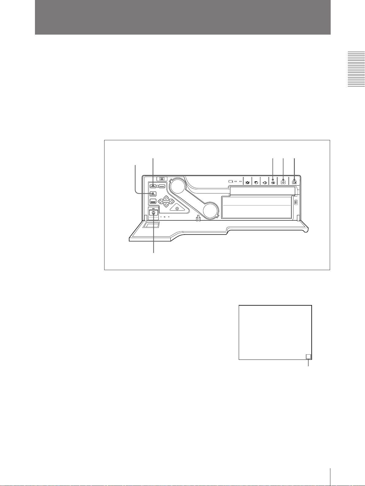
Front ............................................................................... 82
Sub Panel........................................................................ 84
Rear ................................................................................ 85
Monitor Display ............................................................. 86
Index.................................................................................88
Tabel of Contents
4
Page 5

Introduction
About This Manual
This manual is divided into four chapters. This section explains the organization of
this manual.
Introduction
Describes the features and system configuration of the color video printer.
Operation
Describes actual printing once all connections and adjustments have been made, as
explained in the next chapter. You will be able to make various types of printouts
after reading through this chapter.
Installation and adjustment
Describes how to make connections and make adjustments using the menus
displayed on the video monitor. Once all connections and adjustments have been
made, there should be no need to perform these operations again during normal
printing operations. These operations must, however, be performed after
reinstalling, or if the picture quality degrades, or if adjustment becomes necessary
because the peripheral equipment is changed. Also covered is the use of the
printer’s remote control unit (not supplied).
Conventions used
Others
Notes the precautions to be observed when using the printer, lists errors, warnings
and their handling, and explains troubleshooting. Also provided is information on
the locations and functions of parts and controls, and the on-screen messages and
menus used to operate the printer. Should you encounter any unfamiliar terms or
items while reading this manual, consult the index at the end of the manual.
Cross references
Throughout this manual you will find references to other sections of the manual
that contain related information.
Important note
Be sure to read the sections of the manual marked Note . They explain points that
you should be aware of to operate the printer correctly and prevent malfunctions.
Index
Use the index, in addition to the table of contents, to find information you need
when using the printer.
Monitor displays
Some monitor displays illustrated in this manual may differ slightly from the acutal
display. The operation of the printer, however, remains as described in this manual.
Note
Introduction
5
Page 6
System Overview
The UP-2100/2100SD color video printer is designed for capturing images from
video equipment such as VTR and for printing out high-resolution images, either in
256 shades in full color (about 150 dpi). You can make various types of printouts.
You can also add a caption onto the printout. You can operate the daily printer
operation by using the buttons and setup the printer interactively by picking from
displayed menus.
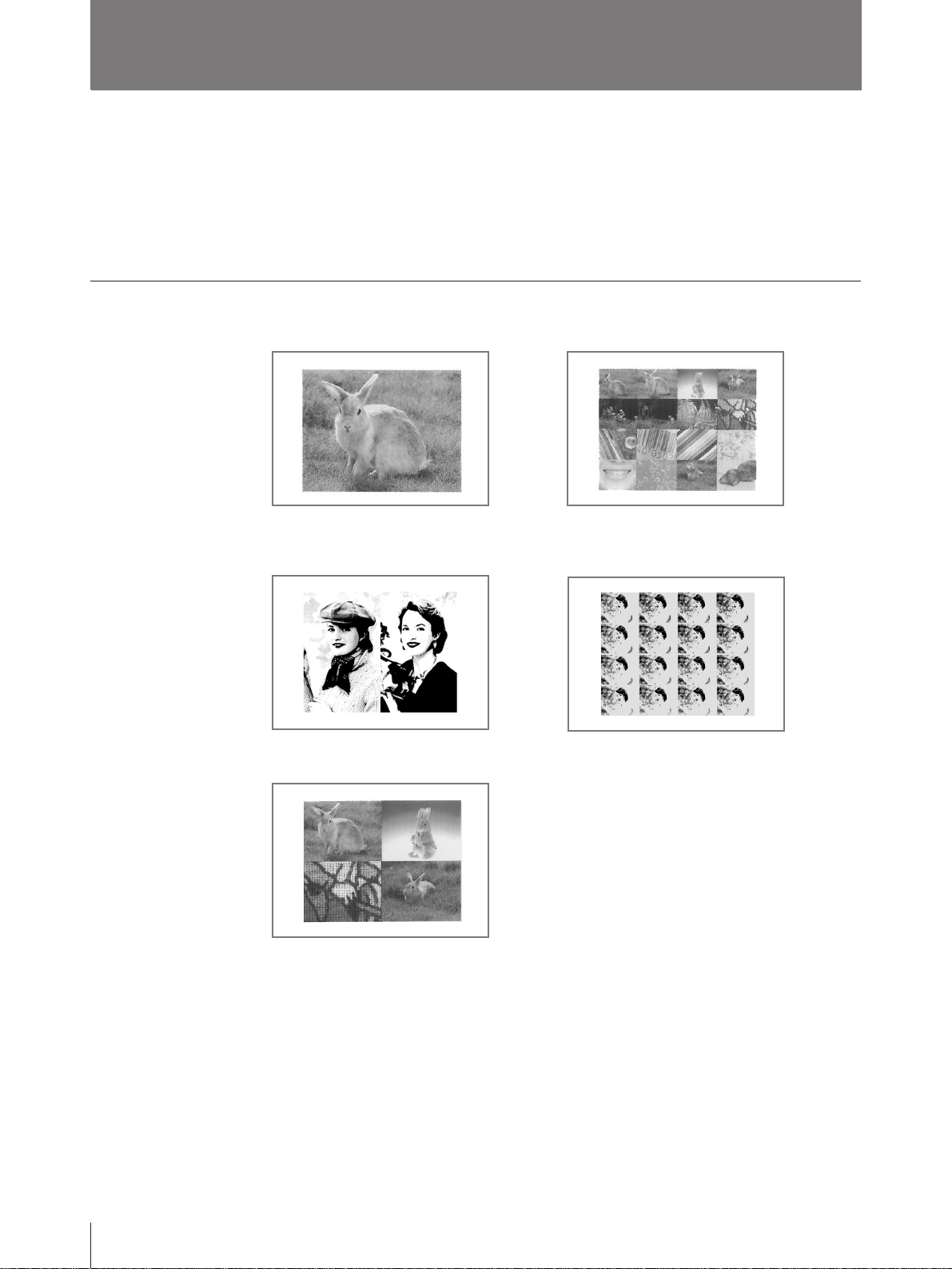
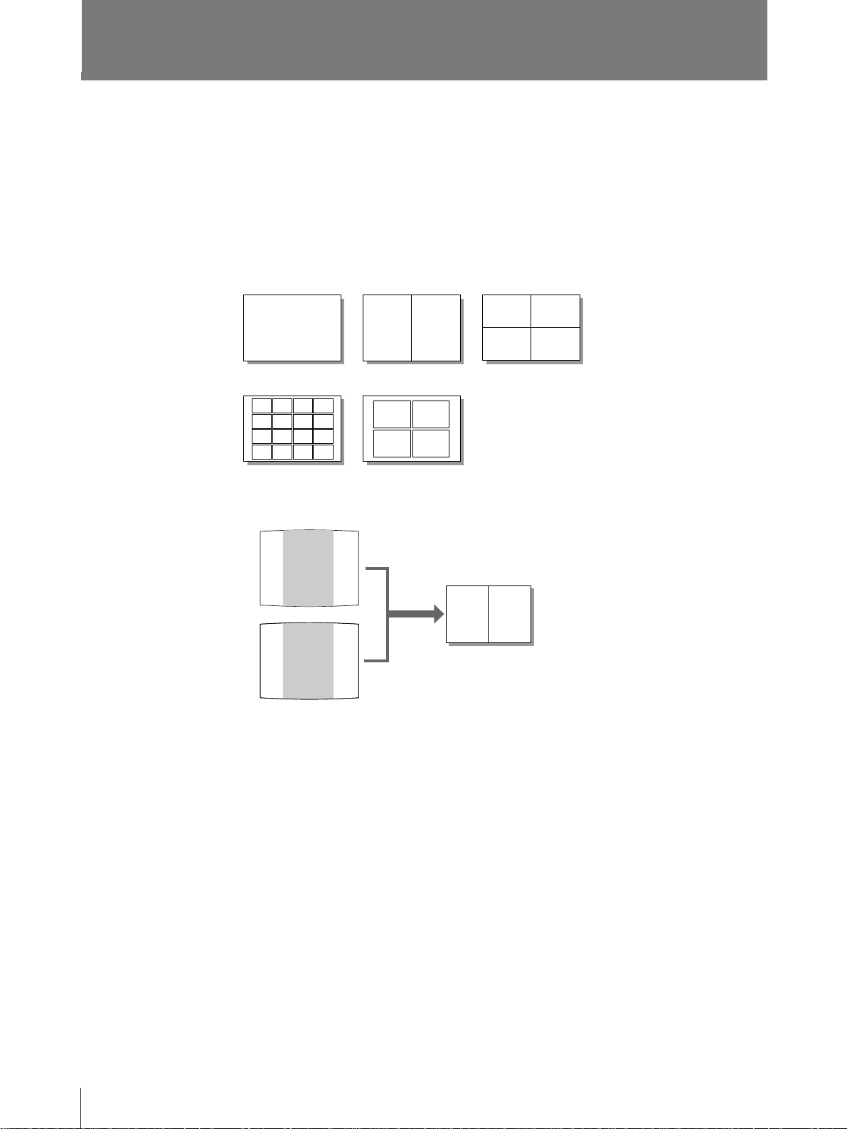
Printouts that can be made with the printer
Printout of a full-size image (page 15)
Printout of two reduced images
Capturing the center of the
screen (page 29)
Printout of four reduced images
(page 29)
Printout of 16 reduced images (page 29)
Printout of identical images (page 38)
6
In addition to the above printouts of multiple reduced images, printouts of multiple
reduced images with white borders can be made.
You can add a caption onto printouts introduced here.
Introduction
Page 7
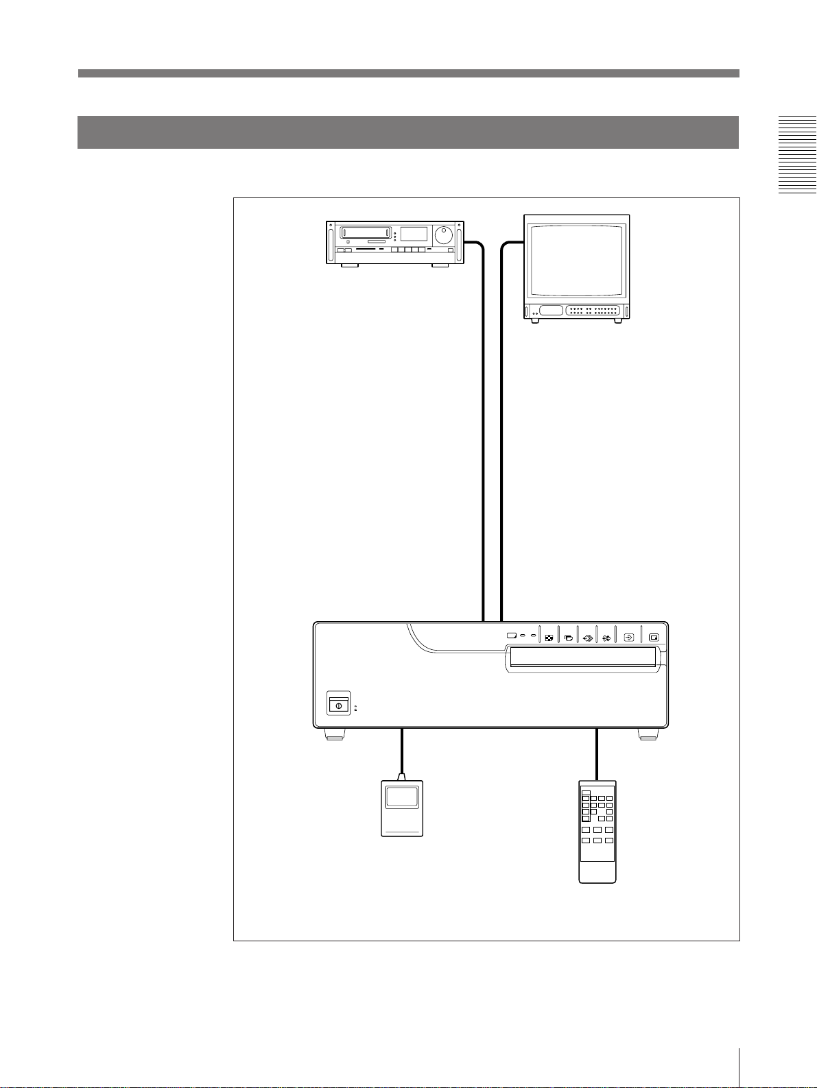
System Configuration
The following shows an example printer system configuration.
Video source
Provides the video input for
printing. Connect a video
source such as video
recorder, video disk player
or similarly.
Video monitor
Displays the images received
from the video source (source
image) and the image to be
printed (memory source). Also
displays the printer menus and
messages.
When the printer power switch is
set to off, you can view the image
of the video source.
Foot switch (not supplied)
Allows you to operate the
printer remotely.
Color Video Printer
Remote control unit (not supplied)
Allows you to operate the printer
remotely.
Introduction
7
Page 8
Operation
Before Printing
This section describes the following operations that must be made prior to starting
printing after mounting the paper tray and paper cover on the printer and making
the necessary connections.
• Loading an ink ribbon cartridge (see below)
• Loading paper (see page 11)
• Selecting the input signal (see page 13)
Once the above operations have been completed, there should be no need to repeat
them during routine printing. Perform them only when absolutely necessary.
Loading an Ink Ribbon Cartridge
To make printouts, an ink ribbon cartridge and paper (which are compaticble) must
be loaded.
If the printer detects an incompatible combination, an error message appears.
Use the ink ribbon cartridge and print paper (supplied) to check if the video printer
functions properly.
Notes
• Use only ink ribbon cartridge and paper “UPC-2010 Color Printing Pack”, that
are designed for use with this printer. Failing to do so is likely to result in
unsatisfactory printing or malfunctions.
• When replacing the ink ribbon cartridge, do not turn off the power. Turning off
the power will cause the image stored in the memory to be lost.
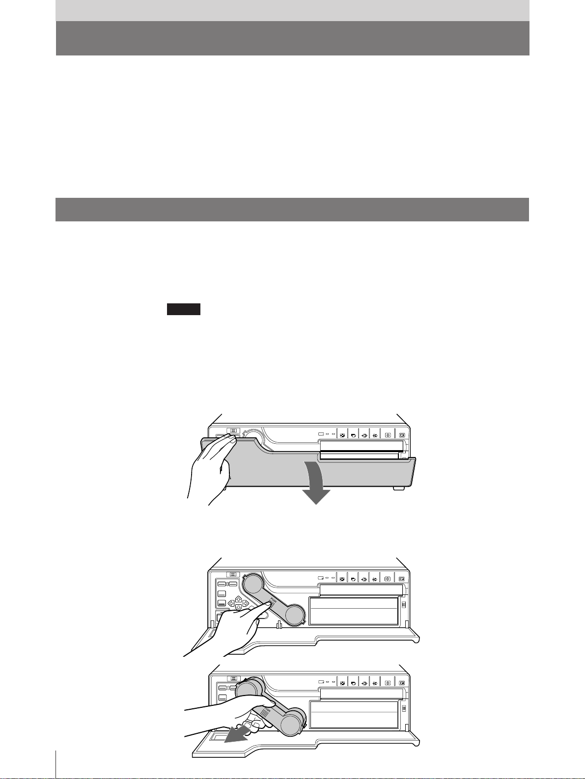
1 Open the front panel by pulling the front panel top toward you.
2 Remove the ink ribbon cartridge by pushing the ink ribbon cartridge itself.
The ink ribbon cartridge pops out.
When you use the printer first, this operation is not required.
8
Operation
Page 9
Note
Never put your hand into the ink ribbon compartment. The thermal head
becomes very hot. You may burn yourself if you touch it.
When the ink ribbon cartridge cannot be ejected
Turn the power off, then back on again. Then, after a while, press the ink ribbon
cartridge.
In this case, the image in memory will be lost.
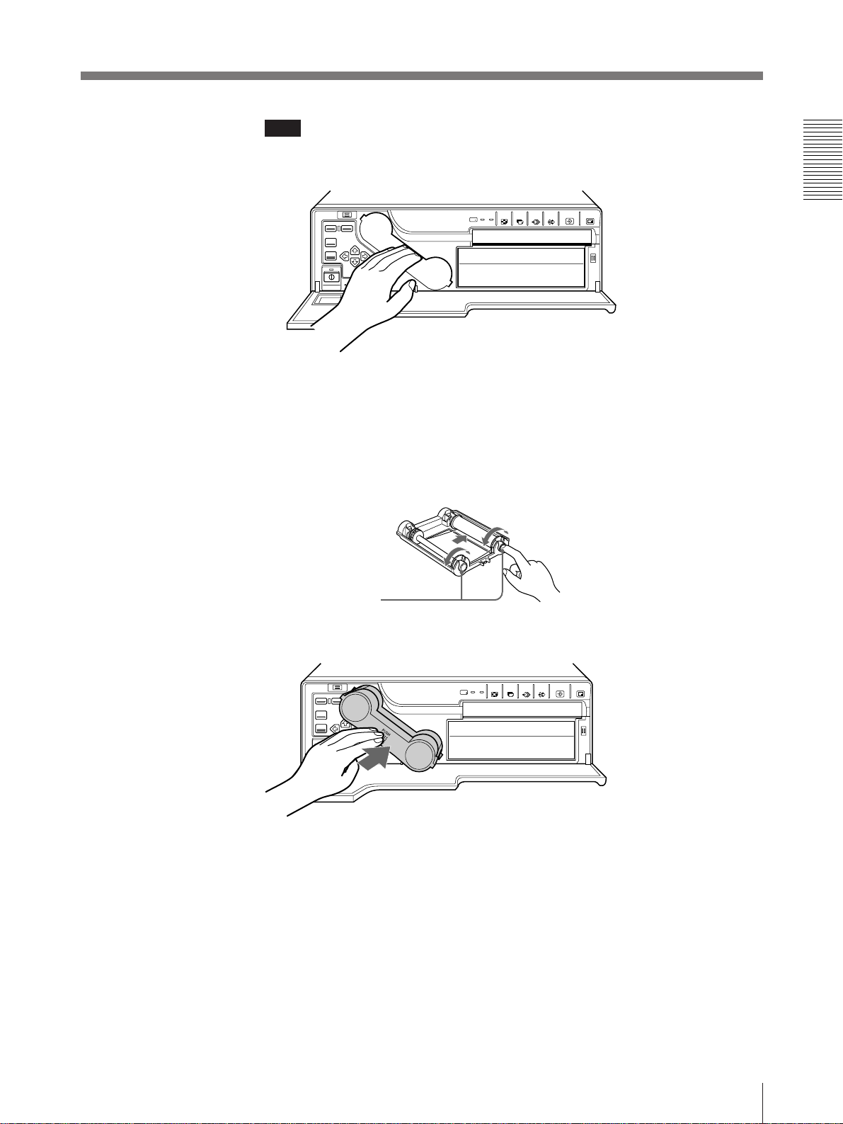
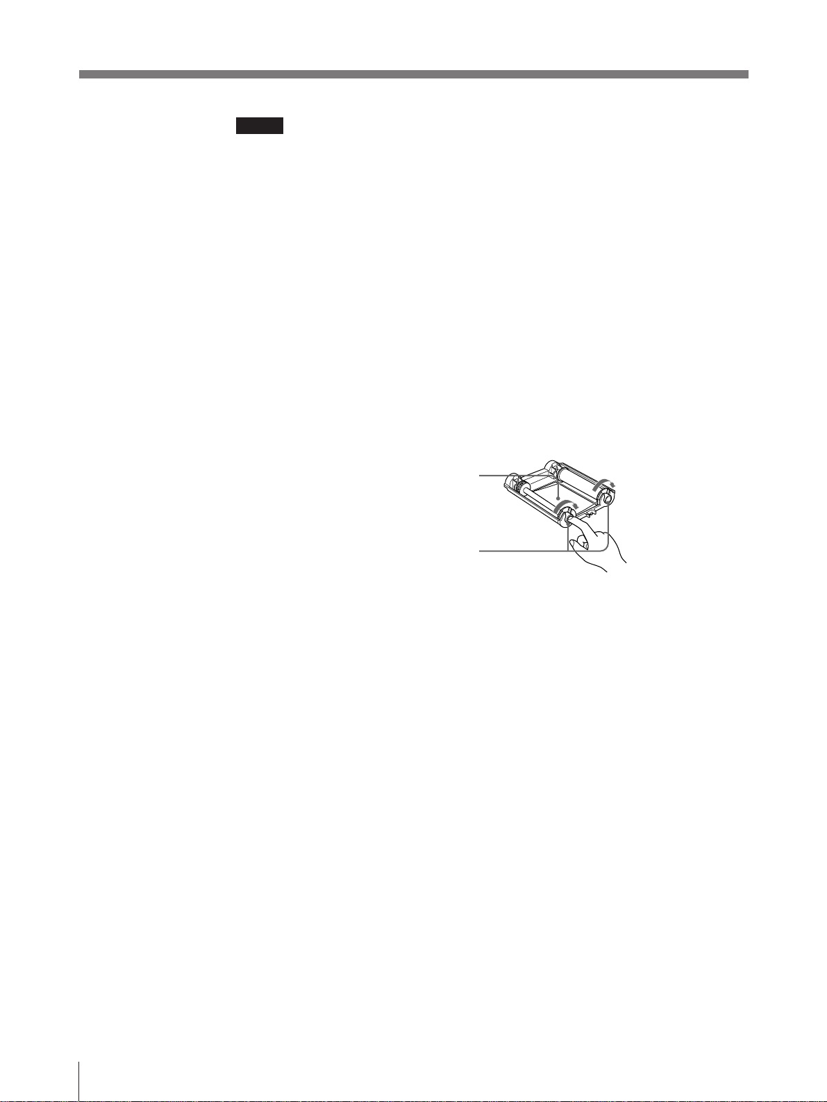
3 Remove any slack from the ink ribbon.
If the ribbon is left slack, it may be damaged when inserted.
Wind the spool until
the not-used part
comes to the right end.
4 Insert the ink ribbon cartridge firmly until it stops.
When the ink ribbon cartridge cannot be inserted
Turn the power off, then back on gain. Then, insert the ink ribbon cartridge.
5 Close the front panel.
Operation
9
Page 10
Before Printing (continued)
Notes
When using ink ribbon cartridge
• Once an ink ribbon cartridge has been completely used, replace it. Ink ribbon
cartridges are not reusable.
• Do not touch the ink ribbon cartridge or place it in a dusty location. Finger prints
or dust on the ink ribbon will result in imperfect printing or malfunction of the
head.
When storing ink ribbon cartridge
• Avoid placing the ink ribbon cartridge in a location subject to:
— high temperatures
— high humidity
— excessive dust
— direct sunlight
• Store a partially used ink ribbon cartridge in its original packaging.
If your ink ribbon should tear
Repair the tear with transparent tape. There should be no problem with using the
remaining portion of the ribbon.
Transparent tape
Turn the spool in the direction of
the arrow to remove any slack
until the transparent tape cannot
be seen.
10
Operation
Page 11

Loading Paper
To load paper, follow the procedure below. Be careful not to touch the printing
surface.
Notes
• Use only ink ribbon cartridge and paper “UP-2010 Color Printing Pack”, that are
designed for use with this printer. Failing to do so is likely to result in
unsatisfactory printing or malfunctions.
• When loading the paper while the printer is operating, do not turn off the power.
Turning off the power will cause the image stored in memory to be lost.
• Do not touch the ink ribbon when handling the paper.
1 Open the front panel by pulling the front panel top towards you.
2 Push the part marked with PUSH on the paper tray.
The paper tray pops out.
3 Place the paper in the paper tray.
Notes
• When adding paper to a partly full tray, be careful that the total number of
sheets does not exceed the limit. If you exceed this limit, paper jams may
occur.
The limit is the amount of paper coutained in one printing pack.
For detailed information on the maximum amount of paper that the paper tray
can hold, see “Ink Ribbon Cartridge and Paper” page 50.
• Load the paper so that it lays flat in the paper tray. If the paper is curled, it
will overflow from the paper tray and the printing position may shift. If this
happens, load fewer sheets in the paper tray.
Continue to next page
m
Operation
11
Page 12

Before Printing (continued)
Place the paper in the paper tray
with the printing surface facing up
Set the paper securely under
the tab.
Printing surface
PUSH
Front
4 Slide the paper tray back into the printer until it clicks into place.
Riffle the paper
5 Close the front panel.
Notes
When handling the paper
Do not touch the printing surface. Dust or finger prints are likely to cause
unsatisfactory printing or malfunction of the head. Hold the paper by the printing
surface protection sheet.
When storing the paper
• Avoid storing the paper in a location subject to:
— high temperatures
— high humidity
— excessive dust
— direct sunlight
• Use the original package for storing unused paper.
12
Operation
Page 13

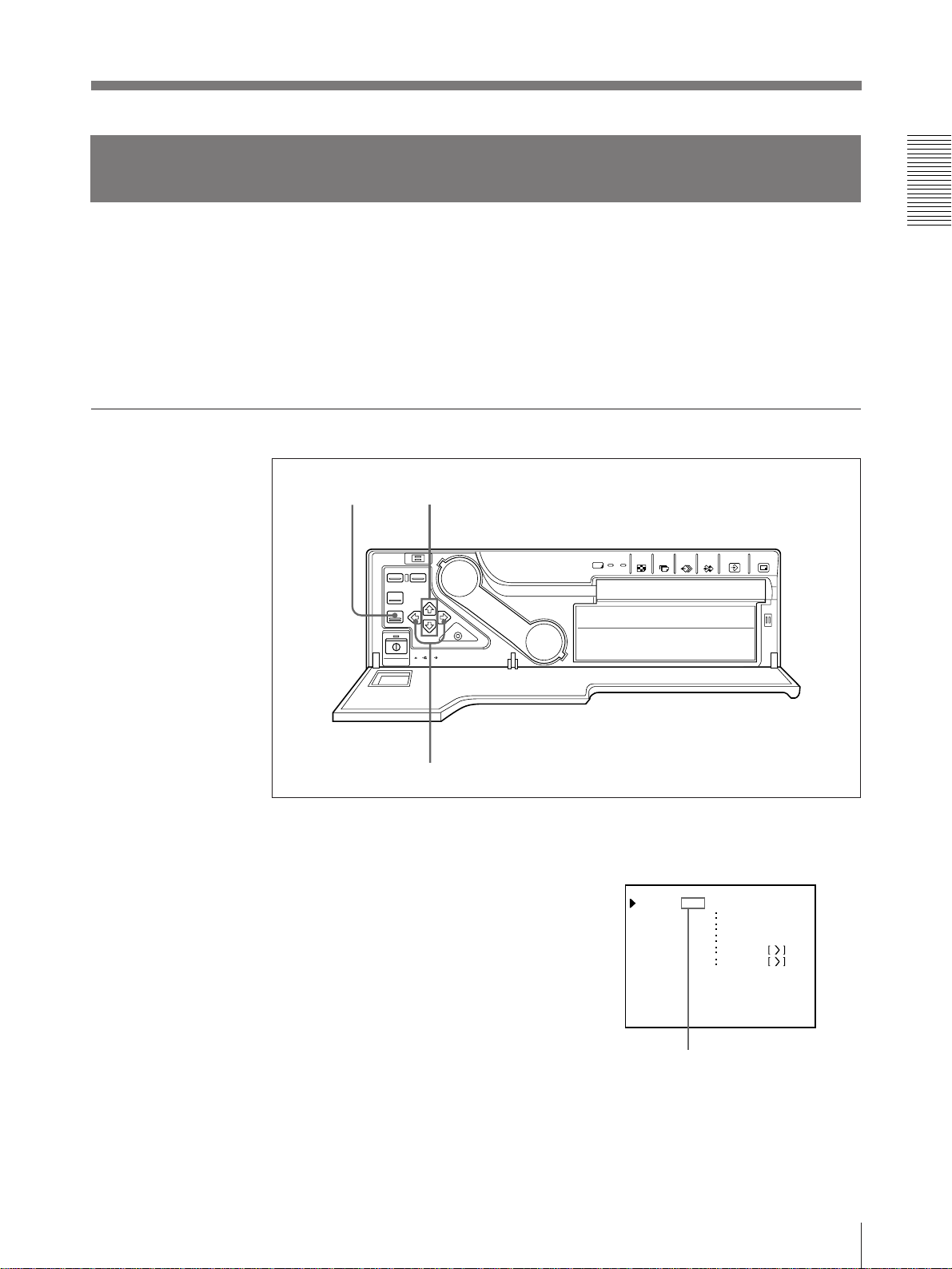
Selecting the Input Signal
I NP U T SE T UP COLOR n n n
GAI N
I NP U T SE L
/ P I X / L A Y / PR N / I N / OUT /
HUE
CO LOR
OFFSET
Q 1 A
1
S
0
0
2
VIDEO/SV
AGC
OF F/ON
0
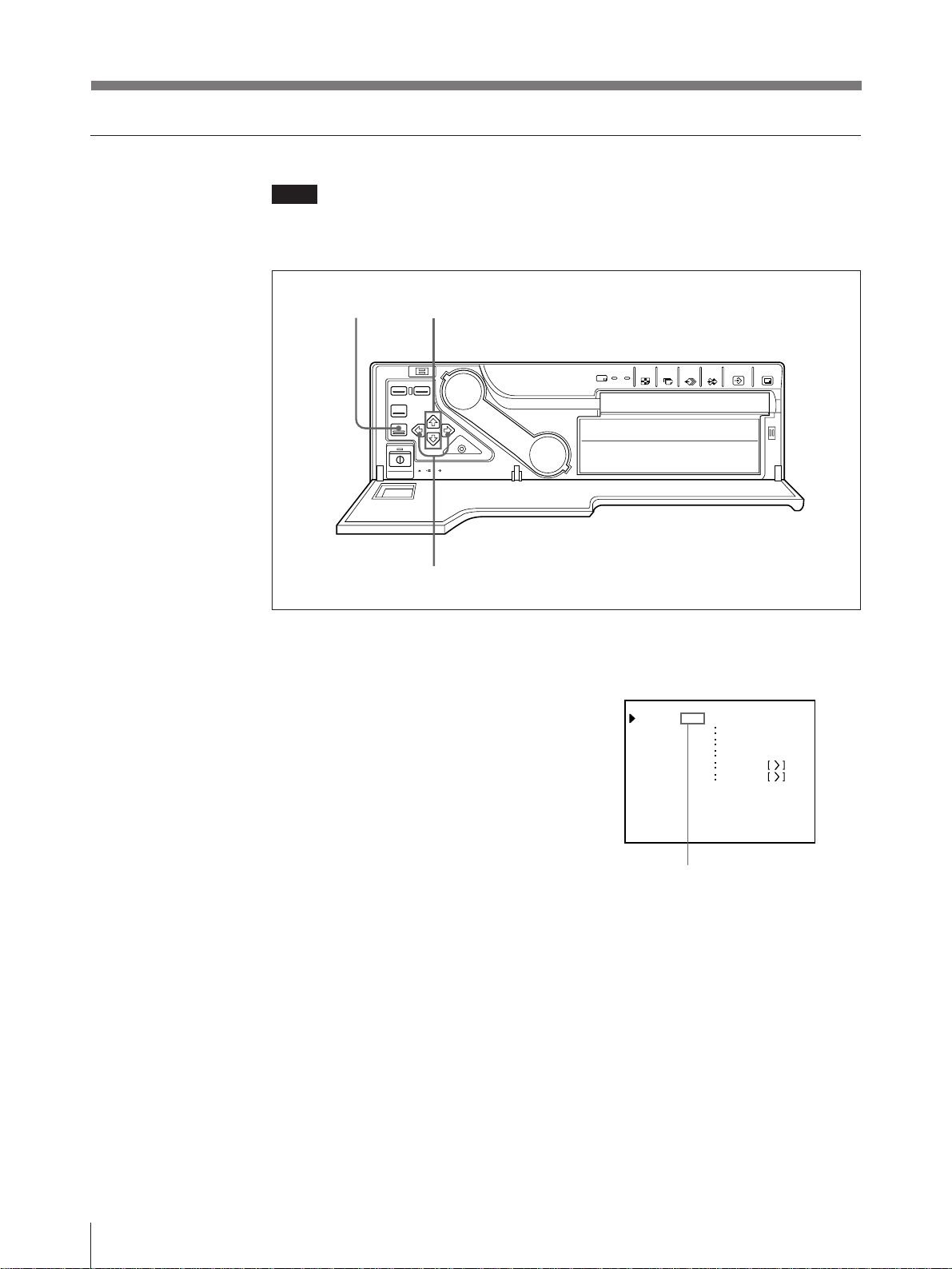
Before printing, select the input signal (the input connector to which the signal to
be printed is being input—VIDEO or S-VIDEO. Once you have selected the input
signal, this setting remains effective until you select another source.
2, 6
1
4
3, 5
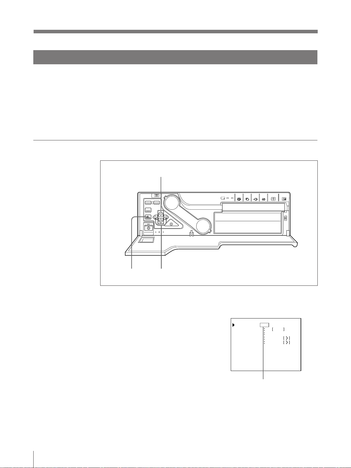
1 Turn on the video monitor and the
printer.
The right screen appears.
Video monitor screen
Q 1 A
1
S
2 Press the MENU button.
The screen previously opened appears.
3 Select IN by pressing the ı or ∫
button.
By switching IN to green with the ı or
∫ button, INPUT SETUP appears.
Continue to next page m
Operation
13
Page 14
Before Printing (continued)
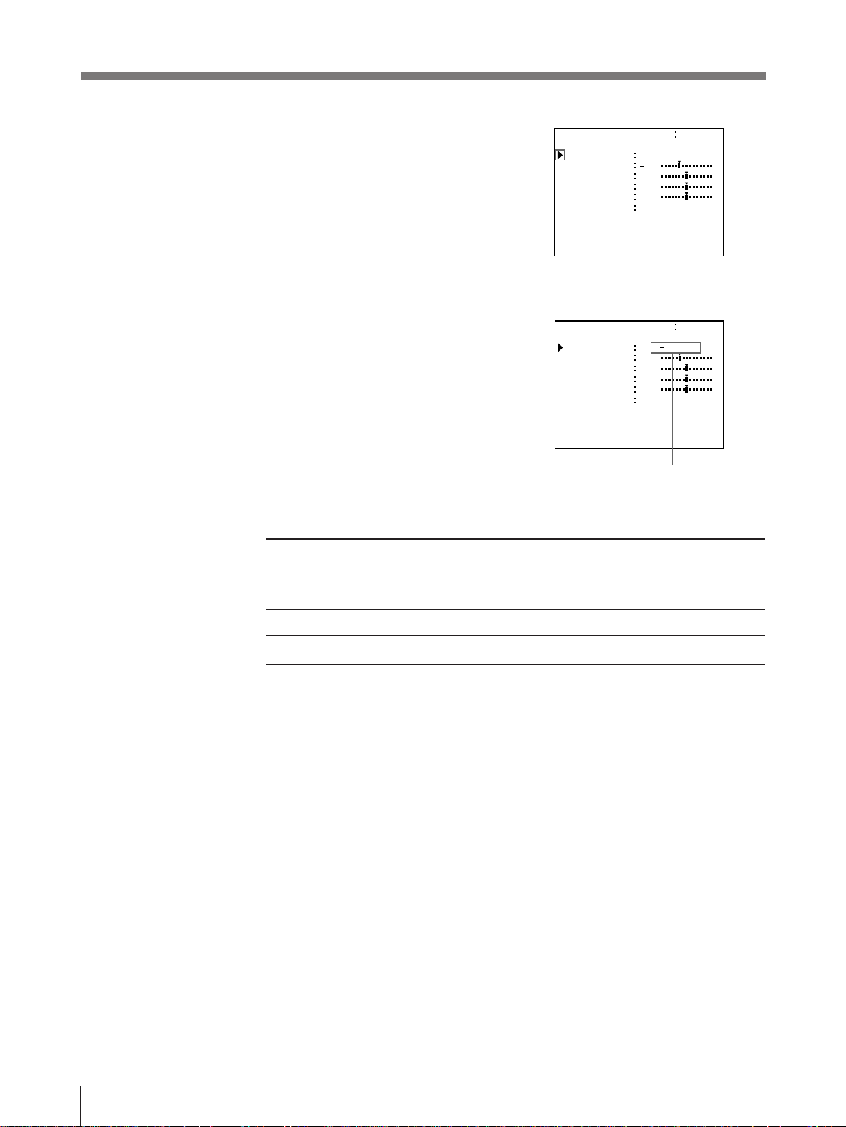
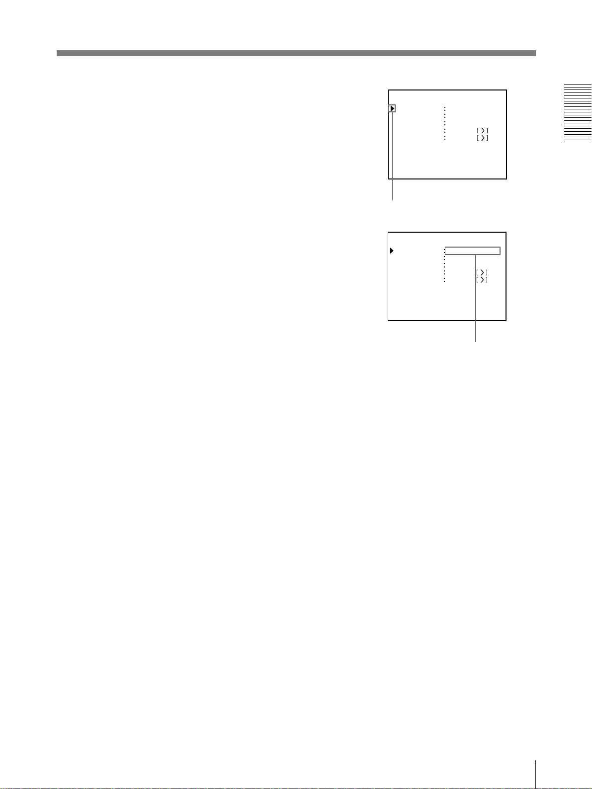
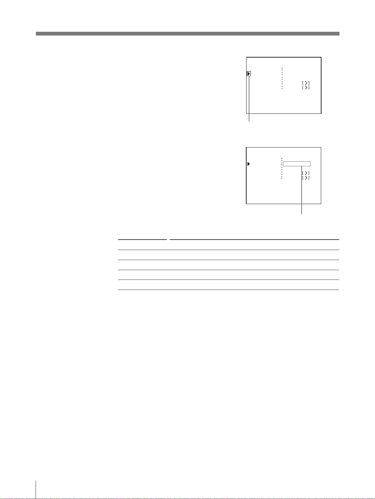
4 Select INPUT SEL by pressing the ◊ or
√ button.
5 Select the input signal by pressing the
ı or ∫ button.
I NP U T SE T UP COLOR n n n
/ P I X / L A Y / P R N / IN / OUT /
I NP U T SE L
HUE
CO LOR
GAI N
OFFSET
AGC
Q 1 A
Position the cursor to INPUT SEL
by pressing the ◊ or √ button.
I NP U T SE T UP COLOR n n n
/ P I X / L A Y / P R N / IN / OUT /
I NP U T SE L
HUE
CO LOR
GAI N
OFFSET
AGC
Q 1 A
Switch the desired input signal to
green by pressing the ı or ∫
button. The selected input signal
turns green and is spelled out.
VIDEO/SV
2
0
0
0
OF F/ON
1
V/S VIDEO
2
0
0
0
OF F/ON
1
S
S
Source signal of the image to be printer Video monitor and
Signal from video equipment connected to the VIDEO INPUT connector V n VIDEO
Signal from video equipment connected to the S-VIDEO INPUT connector SV n S VIDEO
printer window
display (the selected
input signal is
spelled out)
6 Press the MENU button.
The regular screen appears.
14
Operation
Page 15
Making Full-Size Printouts
This section explains how to make a full-size printout. The operations described
here constitute the basic procedure for making a printout.
Before making a full-size printout
• All connections should have already been made. (see page 53)
• Ensure that the appropriate ink ribbon cartridge/paper set is being used and that
they are correctly loaded. (see pages 8, 11 and 50)
• Select the input signal to be used to make a printout. (see page 13)
• Set the printer to store one full-size image into memory. (see page 29)
• Select the appropriate memory page. (see page 28)
DISPLAY
OFF
button
STOP button
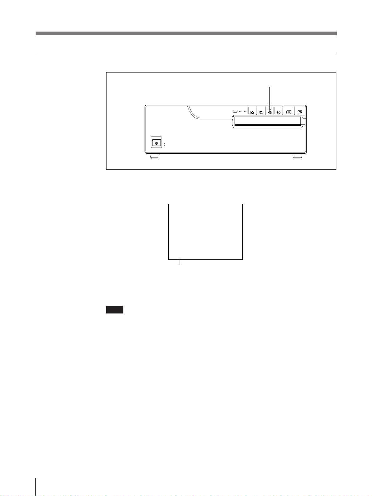
1
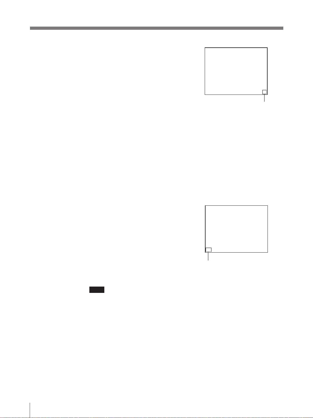
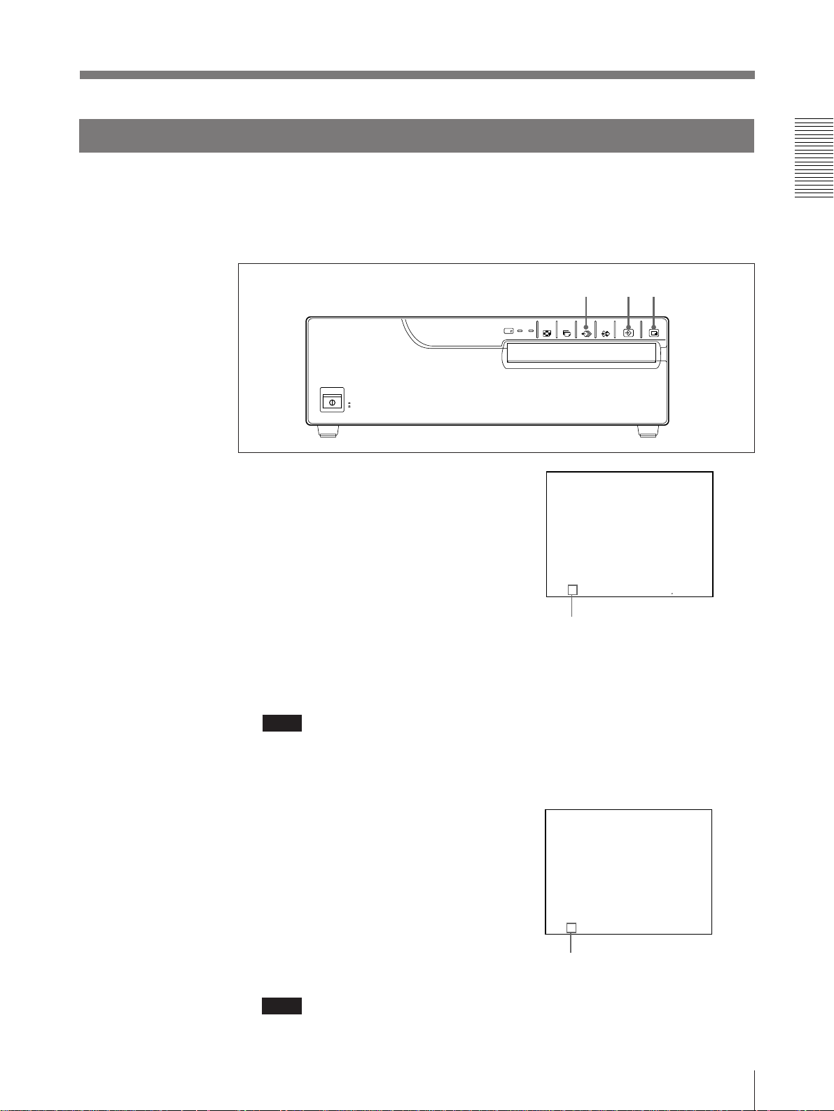
1 Turn on the video monitor and the
printer.
2 Start the video source.
This operation is done using the
controls of the video equipment acting
as the source.
SOURCE/MEMORY button
3
4
Q 1 A 1 S
Shows that the image from
source equipment is
displayed on the video
monitor screen.
Continue to next page m
Operation
15
Page 16
Making Full-Size Printouts (continued)
3 Press the CAPTURE button at the
instant when the image you want to
print appears on the screen.
The image is captured into memory.
The memory image is displayed on the
screen. Which image appears after this,
the source image or memory image,
depends on the setting made with
AUTO LIVE on the FUNCTION
SETUP menu (page 34).
If the stored image is blurred
A quickly moving image may be blurred when printed. Should this occur,
change the MEMORY setting to FIELD on the LAYOUT SETUP menu.
Although the blur should be eliminated, the ultimate print quality will be
slightly degraded.
To change the image in memory
1 To display the source image when the memory image is displayed on the
screen, press the SOURCE/MEMORY button .
2 Press the CAPTURE button at the instant the image you want to print
appears. The previous image is replaced with the new one.
Q 1 A 1 M
Shows that the image captured in
memory is displayed on the video
monitor screen.
4 Press the PRINT button.
It takes about 60 seconds to make a
printout.
The printout pops out from the paper
tray.
Q 1 A 1 M
Blinks while printing
During color printing: Printing
start - yellow - magenta cyan - printing end
Note
• Do not turn off the power during printing.
If you do so, paper may not be ejected and may jam in the printer.
• Do not pull the paper from the paper cover until printing has been completed.
• You can not change the printer application mode or settings on the WINDOW
SETUP menu during printing.
16
Operation
Page 17

To stop printing
Press the STOP button. After the current printing is completed, the remaining
printing is cancelled and the printer stops its operation.
If the printer does not print
The printer will fail to print in the following cases:
• While an error message is displayed on the monitor screen.
— In this case, the paper is ejected without printed even if you press the PRINT
button. Proceed as described in “Error/Warning Messages” on page 77.
• Image is not stored in the memory.
— Image data stored in the memory is lost if you turn off the power. Cature the
image into memory again, then press the PRINT button.
When you want to see an image that is hidden below a screen
message
You can erase the screen message from the video monitor screen by pressing the
DISPLAY OFF button. The screen message disappears. To disply a screen
message, press the DISPLAY OFF buton again.
If a black line appears on the printout
Sometimes, a black line appears on the printout, although it does not appear on the
video monitor. This black line can be eliminated from the printout. (see “Changing
the Printout Size/Printout Area” page 62)
If the image quality of printouts is not satisfactory
You can adjust the image quality of the printouts. (See “Adjusting the Printout
Color” pages 59)
Notes
When storing your printouts:
• Avoid storing the printout in a location subject to high temperatures, high
humidity, excessive dust and direct sunlight.
• Do not stick tape on a printout. Also, avoid leaving a plastic eraser on a printout
or placing a printout in contact with materials which contain plasticizer (under a
desk mat, for example).
• Do not allow alcohol or other volatile organic solvents to come into contact with
the printouts.
Operation
17
Page 18
Making Full-Size Printouts (continued)
Making Multiple Copies of Identical Printouts
You can make up to 9 copies of identical printouts.
The following two methods are available to set the number of printouts.
• On the menu
• Using the PRINT QTY button. However, you cannot decrease the number of
printouts.
The following steps can be performed either before you start printing or while
printing. You can change the designated number of copies any time during
printing.
Setting the printout quantity on the menu
3
1, 5
1
Press the menu botton.
The menu previously opened appears.
2, 4
2 Select PRN by pressing the ı or ∫
button.
The PRINTER SETUP menu arrears.
PR I NTER SETUP CO LOR n n n
/ P I X / LAY / PR N / I N / OUT /
P R I NT QT Y
GAMMA D / NORMA L / L
SYSTEM PRE SS
F UNCT I ON PRE SS
Q 1 A
By switching PRN to green by
pressing the ı or ∫ button,
PRINTER SETUP appears.
1 1~9
1
S
18
Operation
Page 19

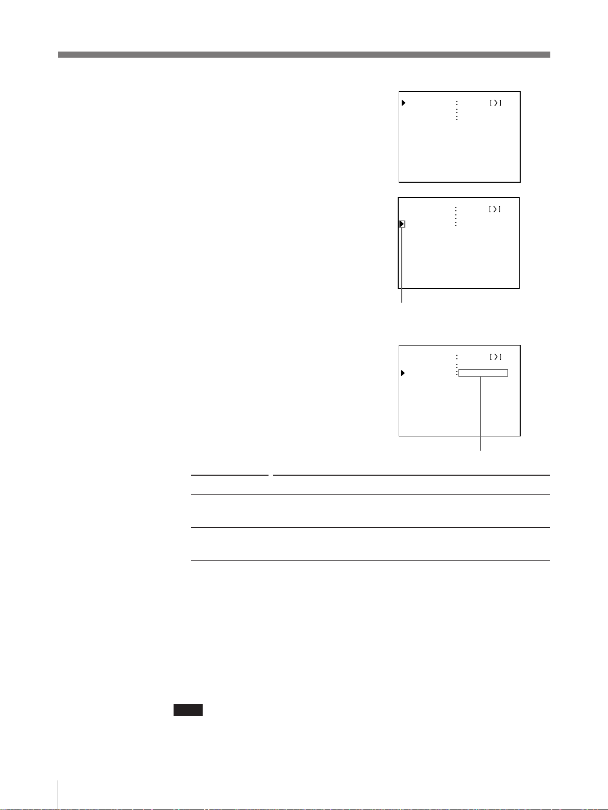
3 Select PRINT QTY by pressing the ◊
or √ button.
PR I NTER SETUP CO LOR n n n
/ P I X / LAY / PR N / I N / OUT /
P R I NT QT Y
GAMMA D / NORMA L / L
SYSTEM PRE SS
FUNCT ION PRE SS
1 1~9
4 Set the number of copies by pressing
the ı or ∫ button.
When setting Button
To increase the quantity ∫
To decrease the quantity ı
5 Press the MENU button.
The regular screen appears.
Q 1 A 1
Position the cursor to PRINT QTY
by pressing the ◊ or √ button.
PR I NTER SETUP CO LOR n n n
/ P I X / LAY / PR N / I N / OUT /
P R I NT QT Y
GAMMA D / NORMAL / L
SYSTEM PRE SS
FUNCT ION PRE SS
Q9 A
Quantity of copies
1
9 1~9
1
S
S
Operation
19
Page 20

Making Full-Size Printouts (continued)
Setting the printout quantity by using the PRINT QTY button
1 Press the PRINT QTY button.
The right screen appears.
If you do not perform any operation
after you press the PRINT QTY button,
the currently set number of copies
appears for 2 or 3 seconds, after which
it disappears.
1, 2
P R I NT QT Y
1 1–9
2 Press the PRINT QTY button until the desired number appears.
Repeatedly pressing the PRINT QTY button increases the quantity up to 9 and
stops.
To decrease the number of copies
When decreasing the number of copies, you have to change the number on the
menu.
If the paper runs out during printing
Load the paper into the paper tray and press the PRINT button. The printer prints
the remaining copies.
The currently set number of copies
appears within a couple of seconds.
20
Operation
Page 21
Capturing Another Image While Printing
While the printer is printing, you can capture another image into another memory
page to be printed once the printer becomes free. The usable memory pages depend
on the type of printouts and settings. (pages 25 and 26)
When the FIELD memory mode is selected, you can capture another image into
another memory.
Select the desired memory page by
1
1
23
pressing the MEMORY PAGE button.
Pressing the MEMORY PAGE button
switches the memory page.
Q 1 A2
The available memory
pages appear in white.
1
S
2 Press the CAPTURE button at the instant the image you want to print appears
on the screen.
Note
If you press the CAPTURE button to caputwe the image into memory page
whose image is being printed, “PRINTING MEMORY” appears and the image
cannot be captured.
3 Press the PRINT button.
The image captured in step 2 is queued.
The image is printed as soon as all
previous printing jobs have been
completed.
Q 1 A2
Memory page whose image has been queued for
printing (blinks white on the video monitor)
The memory page display returns to white on the
Note
video monitor once printing has been completed.
Another image cannot be stored into a memory page into which an image has
already been queued for printing. In such a case, the “PLEASE WAIT
RESERVED MEMORY” appears.
1
Operation
M
21
Page 22
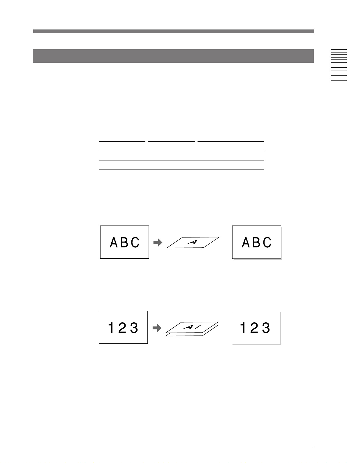
Making Variations of Printouts
You can store various kinds of images into memory and make variations of
printouts using the images captured into memory.
Variations of printouts that the printer can produce
The following variations of printout of the images stored in memory can be made.
Printout of a full-size
image
Printout of two
reduced images
Capturing the center
of the screen
a)
Printout of four
reduced images
A B C 123
A B C
Printout of 16
reduced images
a) In 2H print mode, the image in the center of the screen is captured in memory.
Video monitor
ABC
ABC
Printout of identical
images
123
b)
DEF DEF
DEF DEF
ABC
2H of MULTI PIX
XYZ 456
Printout
123
123
22
The range to be
captured
b) 4 or 16 identical images are printed in one proitout in one sheet of paper.
Operation
Page 23

Selecting the Printer Application Mode
The unit allows you to make printouts according to your need, such as regular
printouts.
You can select the application mode of the printer on the SYSTEM SETUP menu.
When you use the printer first time, the standard application mode for regular
printouts is selected.
Select the application mode according to what kind of printouts you want to make.
1, 9
3, 5, 7
2, 6 4, 8
1 Press the MENU button.
The menu previouly opened appears.
2 Select PRN by pressing the ı or ∫
button.
The PRINTER SETUP menu apperas.
PR I NTER SETUP CO LOR n n n
/ P I X / LAY / PR N / I N / OUT /
P R I NT QT Y
GAMMA D / NORMA L / L
SYSTEM PRE SS
F UNCT I ON PRE SS
1 1~9
3 Select SYSTEM by pressing the ◊ or √
button.
Q 1 A
By switching PRN to green by
pressing the ı or ∫ button,
PRINTER SETUP appears.
PR I N TER SE T UP COLOR n n n
/ P I X / LAY / PR N / I N / OUT /
P R I NT QT Y
GAMMA D / NORMA L / L
SYSTEM PRE SS
FUNCT ION PRE SS
Q 1 A
Position the cursor to SYSTEM
by pressing the ◊ or √ button.
1
1 1~9
1
Continue to next page m
Operation
S
S
23
Page 24
Making Variations of Printouts (continued)
4 Press the ∫ button.
The SYSTEM SETUP menu appears.
5 Select APPLI. by pressing the ◊ or √
button.
6 Select the desired application mode by
pressing the ı or ∫ button.
SY ST EM SE T UP COLOR n n n
PRN SE TUP
BEEP OF F / ON
APPLI.
Q 1 A
SY ST EM SE T UP COLOR n n n
PRN SE TUP
BEE P OF F / ON
APPLI.
Q 1 A
Position the cursor to APPLI.
by pressing the ◊ or √ button.
SY ST EM SE T UP COLOR n n n
PRN SE TUP
BEE P OF F / ON
APPLI.
PRESS
STANDA RD /
1
PRESS
STANDA RD /
1
PRESS
/ DUPL I CATE
S
S
Q 1 A
Switch the desired mode to green
by pressing the ı or ∫ button.
Application mode Printout
STANDARD Printout with a full-size image, two different reduced images, four different
reduced images and 16 different reduced images
DUPLICATE Printouts of a full-size imagea), four identical reduced images and 16 identical
reduced images
a) The printer prints in field mode when a full-size image printout is selected in DUPLICATE mode.
It is recommended to make a full-size printout in STANDARD mode.
DUP1
S
7 Select PRN SETUP by pressing the ◊ or √ button.
8 Press the ∫ button.
The PRINTER SETUP menu appears.
9 Press the MENU button.
The regular screen appears.
Note
Chaning the appliction mode results in clearing images stored in all of memory
pages.
24
Operation
Page 25
About the Memory
To make printouts, it is first necessary to capture the image into memory.
When capturing the image, there are two ways to use the memory, one is frame
mode and the other is field mode.
Frame mode: A image is captured in one memory.
Field mode: A memory is divided into two, and images can be captured in each.
A memory in which an image is captured is called memory page in this manual.
The number of usable memory pages depends on the type of the selected reduced
images and memory mode.
Reduced image Memory mode Number of memory pages
1/2H/4/16 Frame 1 (A)
1/2H Field 2 (A1, A2)
When you select four-reduced image mode or 16-reduced image mode, the unit
selects automatically frame mode regardless of the setting of MEMORY on the
LAYOUT SETUP menu.
In frame mode
Video monitor screen
Q 1 A
The image displayed in
the video monitor is
captured in the memory
page A.
1
In field mode
Video monitor screen
Q 1 A 1
The image displayed in
the video monitor is
captured in the memory
page A1.
1
Printout
S
A still subject can be printed with
high resolution.
Printout
S
A quickly moving subject can be
printed without blurring.
Operation
25
Page 26
Making Variations of Printouts (continued)
Selecting the memory mode
Note
You can select the desired memory page only when 1 or 2H is selected in
STANDARD mode.
1, 5
3
2, 4
1 Press the MENU button.
The menu just before opened appears.
2 Select LAY by pressing the ı or ∫
button.
L AY OU T SETUP CO L OR n n n
/ P I X / L A Y / P R N / IN / OUT /
MEMORY
MUL T I P I X
SEPARATE OFF / ON
WI N DOW PRESS
CAPT I ON PRESS
FRAME/FI ELD
1/2H/4/
16
26
Operation
Q 1 A
By switching LAY to green by
pressing the ı or ∫ button,
LAYOUT SETUP appears.
1
S
Page 27
3 Select MEMORY by pressing the ◊ or
√ button.
L AY OU T SETUP CO LOR n n n
/ P I X / L A Y / P R N / I N / OUT /
MEMORY
MUL T I P I X
SEPARATE OF F / ON
WI N DOW PRE SS
CAPT I ON PRE SS
FRAME/FI ELD
1/2H/4/
16
4 Select the desired memory mode by
pressing the ı or ∫ button.
Q 1 A
Position the cursor to MEMORY
by pressing the ◊ or √ button.
L AY OU T SETUP CO L OR n n n
/ P I X / L A Y / P R N / IN / OUT /
MEMORY
MUL T I P I X
SEPARATE OFF / ON
WI N DOW PRESS
CAPT I ON PRESS
Q 1 A 1
Switch the desired memory mode to
green by pressing the ı or ∫ button.
1
FRAME/FI ELD
1/2H/4/
1
Frame: We recommend that, whenever possible, you print in this mode.
Field: Select this mode to reduce blurring when you print a quickly moving
image.
5 Press the MENU button.
The regular screen appears.
S
16
S
Operation
27
Page 28
Making Variations of Printouts (continued)
Selecting a memory page
To select a memory page, press the MEMORY PAGE button.
MEMORY PAGE button
Q 1 A2 1 S
Select the desired memory page by
pressing the MEMORY PAGE button.
Note
The memory page whose image is being printed is blinking on the video monitor
screen. Even if you select this blinking page, you cannot capture the image in this
page.
28
Operation
Page 29
Making a Printout of Multiple Different Reduced
Images
You can store multiple images into a memory page and make a printout with those
reduced images. This section explains how to make a printout with multiple
reduced images.
A printout having multiple reduced images is done by following the procedure
below.
• Determining the number of reduced images. (on this page)
• Selecting the image on the video monitor after capturing the image (page 33)
• Setting the printer application mode to STANDARD (page 23)
Selecting the number of reduced images to be captured in memory
1, 7
3, 5
2, 4, 6
1 Press the MENU button.
The menu just before opened appears.
2 Select LAY by pressing the ı or ∫
button.
L AY OU T SETUP CO L OR n n n
/ P I X / L A Y / P R N / IN / OUT /
MEMORY
MUL T I P I X
SEPARATE OFF / ON
WI N DOW PRESS
CAPT I ON PRESS
FRAME/FI ELD
1/2H/4/
16
Q 1 A
By switching LAY to green by
pressing the ı or ∫ button,
LAYOUT SETUP appears.
1
Continue to next page m
S
Operation
29
Page 30
Making Variations of Printouts (continued)
3 Select MULTI PIX by pressing the ◊ or
√ button.
4 Select the desired type of reduced-images
printout by pressing the ı or ∫ button.
L AY OU T SETUP CO LOR n n n
/ P I X / L A Y / P R N / I N / OUT /
MEMORY
MUL T I P I X
SEPARATE OF F / ON
WI N DOW PRE SS
CAPT I ON PRE SS
Q 1 A
Position the cursor to MULTI PIX
by pressing the ◊ or √ button.
L AY OU T SETUP CO LOR n n n
/ P I X / L A Y / P R N / I N / OUT /
MEMORY
MUL T I P I X
SEPARATE OF F / ON
WI N DOW PRE SS
CAPT I ON PRE SS
Q 1 A
Switch the desired type of reducedimage printout to green by pressing
the ı or ∫ button.
FRAME/FI ELD
1/2H/4/
1
FRAME/FI ELD
1/2H/4/
2
16
16
HS
S
Displayed type
1
2H
4
16
Number of reduced images
1 (Full-size image)
2 (Two reduced images around the center of the screen)
4 (Four reduced images)
16 (16 reduced images)
To make a printout of reduced images with white borders, go to step 5.
To make a printout without white borders, go to step 7.
30
Operation
Page 31

5 Select SEPARATE by pressing the ◊ or
√ button.
L AY OU T SETUP CO L OR n n n
/ P I X / L A Y / P R N / IN / OUT /
MEMORY
MUL T I P I X
SEPARATE OFF / ON
WI N DOW PRESS
CAPT I ON PRESS
FRAME/FI ELD
1/2H/4/
16
Q 1 A
Position the cursor to SEPARATE
by pressing the ◊ or √ button.
Note
2
HS
In the LAYOUT SETUP menu, if items such as MEMORY and SEPARATE are
not effective, DUPLICATE is selected. In such a case, select the STANDARD mode
in the SYSTEM SETUP menu first.
6 Select whether the images are printed
with or without white borders by
pressing the ı or ∫ button.
When you select Settings
Printouts without white borders OFF
Printouts with white borders ON
L AY OU T SETUP CO L OR n n n
/ P I X / L A Y / P R N / IN / OUT /
MEMORY
MUL T I P I X
SEPARATE OFF / ON
WI N DOW PRESS
CAPT I ON PRESS
Q 1 A
Switch the desired mode to green
by pressing the ı or ∫ button.
FRAME/FI ELD
1/2H/4/
2
16
HF S
7 Press the MENU button.
The regular screen appears.
Operation
31
Page 32

Making Variations of Printouts (continued)
To select the desired type of reduced-image printout using the MULTI
PICTURE button
You can select the number of reduced images using the MULTI PICTURE button
on the front panel.
1 Press the MULTI PICTURE button.
The current setting appears. The video
monitor screen is reset to the regular
screen after a few seconds.
1, 2
MUL T I P I X 1/2H/4/
The currently selected type of
reduced-image printout is lit green.
16
2 Press the MULTI PICTURE button until the desired type of reduced-image
printout appears.
Repeatedly pressing the MULTI PICTURE button switches the type of reducedimage printout
For detailed information on the type of reduced-image printout, see “Selecting the
number of reduced images to be captured in memory”. (page 29)
32
Operation
Page 33

Selecting the images on the video monitor after capturing the image
You can select which image appears on the video monitor, source image or
memory after capturing the image.
1, 7
3, 5
4
2, 6
1 Press the MENU button.
The menu just before opened appears.
2 Select PRN by pressing the ı or ∫ button.
PR I NTER SETUP CO LOR n n n
/ P I X / LAY / PR N / I N / OUT /
P R I NT QT Y
GAMMA D / NORMA L / L
SYSTEM PRE SS
F UNCT I ON PRE SS
1 1~9
3 Select FUNCTION by pressing the ◊ or
√ button.
Q 1 A
By switching PRN to green by
pressing the ı or ∫ button,
PRINTER SETUP appears.
PR I NTE R SE T UP COLOR n n n
/ P I X / LAY / PR N / I N / OUT /
P R I NT QT Y
GAMMA D/ NORMA L / L
SYSTEM PRE SS
FUNCT ION PRE SS
Q 1 A
Position the cursor to FUNCTION
by pressing the ◊ or √ button.
1
1 1~9
1
Continue to next page m
Operation
S
S
33
Page 34

Making Variations of Printouts (continued)
4 Press the ∫ button.
The FUNCTION SETUP menu appears.
5 Select AUTO LIVE by pressing the ◊ or
√ button.
6 Select which the image appears on the
video monitor after the image is
captured by pressing the ı or ∫ button.
FUNCT ION SETUP COLOR: nnn
PRN SE TUP PRESS
AUTO L I VE
IMMED.CAP
RM2 FUNC
CLEAR
Q 1 A
FUNCT ION SETUP COLOR: nnn
PRN SE TUP PRESS
AUTO L I VE
IMMED.CAP
RM2 FUNC
CLEAR
Q 1 A
Position the cursor to AUTO LIVE
by pressing the ◊ or √ button.
FUNCT ION SETUP COLOR: nnn
PRN SE TUP PRESS
AUTO L I VE
IMMED.CAP
RM2 FUNC
CLEAR
OFF / ON
OFF / ON
PRI NT /
ALL/
1
OFF / ON
OFF / ON
PRI NT /
ALL/
1
OFF / ON
OFF / ON
PRI NT /
ALL/
S
S
Q 1 A
Switch the desired mode to green
by pressing the ı or ∫ button.
When you select
The image captured in memory appears just after the printer captures the
image, and the memory image remains on the video monitor screen.
The image stored in memory appears just after the printer captures the
image, then after a few seconds, the source memory appears, whenever
you press the CAPTURE button.
1
7 Press the MENU button.
The regular screen appears.
To return to the PRINTER SETUP menu
In step 9, position the cursor to PRN SETUP and press the ∫ button.
The PRINTER SETUP menu appears again.
S
Setting
OFF
ON
34
Operation
Page 35

Making a printout with multiple reduced images
This subsection explains how to make printouts of multiple reduced images taking, as
an example, the making of a printout of four reduced images.
Before making the printout of four reduced images
• Select the type of the four-reduced image and whether to put the white borders
a)
. (see
page 29)
• Select the appropriate memory page. (see page 28)
• Select which image will appear after the image has been stored into memory, the
memory image or source image. (see page 33)
a) When the type of four reduced images or 16 reduced images is selected, the frame mode is
automatically selected.
5
23
1 Start the video source.
This operation is done using the controls
of the video equipment acting as the source.
Blinks green to indicate that an
image will be captured here.
Q 1 A
The
memory
page into
which four
reduced
images are
captured.
4
Type of
multiple
reduced
images
Indicates that the
images from video
equipment is displayed
on the screen.
Indicates that the white
borders are not attached
around images.
When the white border is
attached, 4F appears.
Continue to next page m
S
Operation
35
Page 36

Making Variations of Printouts (continued)
2 Press the CAPTURE button at the
The blinking green cursor moves.
instant the image you want to print
appears on the screen.
The image has been stored to the star
(*) that blinked green on the video
monitor screen in step 1.
The green blinking star (referred to as
the cursor) on the monitor moves to the
next position.
Q 1 A
4
M
At this time, the image captured in memory is displayed on the video monitor screen.
However, the image to be displayed after a few seconds depends on the setting of
AUTO LIVE in the FUNCTION SETUP menu. (see page 33)
Go to step 3 when the memory image remains on the video monitor screen.
Go to step 4 when the source image is displayed.
3 Press the SOURCE/MEMORY button.
The source image appears on the video monitor screen.
4 Repeat steps 2 and 3 until you have captured four images when the memory image
remains on the video monitor screen.
Repeat step 2 until you have captured four images when the source image appears
on the video monitor screen.
To replace a captured image
Example: When you want to change the image stored to the third position.
1 Select the third position where
there is the image which you want
to replace by pressing the ◊, √, ı
or ∫ button.
Pressing the ◊, √, ı or ∫ button
moves the cursor one position
vertically or horizontally.
Q 1 A
Press the ◊, √, ı or ∫ button until
the third cursor blinks green.
4
M
2 Start the video source.
If the memory image is displayed, press the SOURCE/MEMORY button to
display the source image.
3 Press the CAPTURE button at the instant the image you want to print
appears.
The previously stored image is replaced with the newly stored image.
36
Operation
Page 37

To skip a previously captured image
When an image has already been captured, the previously captured image can
be replaced by pressing the CAPTURE button.
Skip the corresponding image by pressing the ◊, √, ı or ∫ button.
5 Press the PRINT button.
The four reduced images are printed on one sheet of paper.
Making a printout with an insert
You can make printouts with an insert which is reduced image.
Example: To make a printout with one of four reduced images inserted.
The operation to make a printout with one of 16 reduced images is the same.
1 Display the full-size image stored in memory. (Follow steps 1 to 3 of “Making Full-
Size Printouts” on page 15.)
2 Set the multiple reduced image type to 4 (without white borders).
(See “Selecting the number of reduced images to be captured in memory” on
page 29.)
3 Capture the image to be inserted.
1 Select the position where a reduced image
is to be inserted by pressing the ◊, √,
ı or ∫ button.
2 Press the CAPTURE button at the
instant the image you want to insert
appears.
The image is captured to the position
selected in step 1.
Move the green cursor to the position
where the reduced image is inserted.
Q 1 A
4 Press the MULTI PICTURE button.
The full-size image with an insert appears on the video monitor.
5 Press the PRINT button.
The image with an insert is printed.
4
S
Operation
37
Page 38

Making Variations of Printouts (continued)
Making Printouts of Identical Images
The unit supports the application mode such as DUPLICATE that allows you to make
a printout for identical images.
This DUPLICATE mode allows you to make a printout with a full-size image,
identical six reduced images or 16 reduced images.
Before making printouts with identical images
• Select the application mode DUPLICATE. (page 23)
• Decide the number of images. (page 29)
2
3
1 Start the video source.
This operation is done using the controls of the video equipment acting as the source.
2 Press the CAPTURE button at the instant the image you want to print appears on
the screen.
To replace a stored image
1 When the memory image remains on the video monitor screen, press the SOURCE/
MEMORY button to display the source image.
2 Press the CAPTURE button at the instant the image you want to print appears.
The previously copied identical images are replaced with the newly captured
copied images.
3 Press the PRINT button.
The identical reduced images of the same size are printed in a single printout.
38
Operation
Page 39

Making Printouts With a Caption
A caption, such as data or comments, can be added to a printout below the image.
You can input up to 48 characters.
About the CAPTION menu
A caption is entered from the CAPTION menu. You can input caption in any
printer application mode and make a printout with a caption.
Note
A caption may not be cleary printed in Field mode.
A brief explanation of each item of the CAPTION menu is given below.
Character display area
The cursor lit green
indicates the position
where a character can
be entered.
ON: displayed when printing with a caption
OFF: displayed when printing without a caption
(OFF is displayed as the factory-setting)
CAPT ION ON
1
ABCDEFGHI J KLMN
OPQRSTUVWXYZ
0123456789
The entered characters are
displayed here.
Character entry area
The character or symbol
where the cursor is placed
is highlighted green and
this highlighted character is
to be entered.
+
=
–
%
Symbols and words
can be used to enter
a caption.
Symbols and words can be used to enter a caption
Monitor display
INS
DEL
SP
OFF
ON
EXIT
a)
SHIFT
a) By highlighting SHIFT green and pressing the EXEC button, capital letters are changed to lower-
case letters, or lower-case letters are changed to capital letters in the character entry area.
Function
Inserts one character without easing the highlighted character.
Deletes a highlighted character and characters back by one.
Puts one space at the position of the highlighted character as erasing that
character. One space is left.
Selects to print without a caption.
Selects to print with a caption.
Returns from the CAPTION menu to LAYOUT SETUP menu.
Selects either capital letters or lower-case letters.
Operation
39
Page 40

Making Printouts With a Caption (continued)
Entering a Caption
Enter a caption as follows. The setting remains effective until you enter a new
setting - even if you turn the power off.
Notes
• If you turn off the power of the printer without returning to the LAYOUT
SETUP menu or regular screen, the entered characters are cleared.
• During printing, you cannot enter or edit caption in the CAPTION menu.
1
6, 9
34
7
2
1 Press the MENU button.
The menu just before opened appears.
2 Select LAY by pressing the ı or ∫
button.
5, 10
L A YOUT SET UP COL OR n n n
/ P I X / LAY / PR N / I N / OUT /
MEMORY
MUL T I P I X
SEPARATE OFF / ON
WI N DOW PRESS
CAPT I ON PRESS
FRAME/FI ELD
1/2H/4/
16
40
Operation
Q 1 A
By switching LAY to green by
pressing the ı or ∫ button,
LAYOUT SETUP appears.
1
S
Page 41

3 Select CAPTION by pressing the ◊ or
WI NDO W PRESS
MEMORY
MUL T I P I X
1/2H/4/
16
SEPARATE OFF / ON
CAPT I ON PRESS
Q 1 A
1
S
FRAME/FI ELD
L A YOUT SET UP COL OR n n n
/ P I X / LAY / PR N / I N / OUT /
√ button.
Position the cursor to CAPTION
by pressing the ◊ or √ button.
4 Press the ∫ button.
The CAPTION menu appears.
5 Position the cursor (the line lit green) to the point where you want to enter the
character in the character display area.
To move the cursor:
1 Select the arrow corresponding to
the direction in which you want to
move the green cursor in the
character display area, by pressing
the ◊, √, ı or ∫ button.
Example: Move the cursor to the left by two.
The cursor is curenily positioned here.
CAPT ION ON
3
ABCDEFGHI J KLMN
2 Press the EXEC button.
Each time you press the EXEC
OPQRSTUVWXYZ
0123456789
1 Highlight the
ı button
green.
The cursor moves to this position.
CAPT ION ON
+
=
–
%
2 Press the EXEC
button twice.
1
button, the cursor moves one
position in the designated direction.
ABCDEFGHI J KLMN
Note
OPQRSTUVWXYZ
0123456789
+
=
–
%
When OFF is displayed, the CAPTION input mode is set to off. Thus, you
cannot add a caption to the printouts. (“Making printouts with a caption” on
page 44)
Continue to next page m
Operation
41
Page 42

Making Printouts With a Caption (continued)
6 Select the character you want to enter
by pressing the ◊, √, ı or ∫ button.
7 Press the EXEC button.
Example: To enter S
CAPT ION ON 1
ABCDEFGH IJKLMN
OPQRSTUVWXYZ
0123456789
Highlight S green by pressing the
◊, √, ı or ∫ button.
The cursor moves to this position.
+
=
–
%
The character selected in step 6 appears
at the point where the green cursor is
CAPT ION ON
S
positioned in the character display area,
after which the cursor moves to the next
position.
ABCDEFGHI J KLMN
OPQRSTUVWXYZ
0123456789
+
=
–
%
When you enter the wrong character
1 Select ı by pressing the ◊, √, ı or ∫ button, then press the EXEC button.
The cursor moves back by one and the character entered in step 6 is
highlighted green.
2 Select DEL by pressing the ◊, √, ı
or ∫ button.
CAPT ION ON
S
2
1
ABCDEFGHI J KLMN
OPQRSTUVWXYZ
0123456789
Switch DEL to green by pressing
the ◊, √, ı or ∫ button.
+
=
–
%
3 Press the EXEC button.
The character selected in 1 is deleted.
When the character to be deleted is placed among entered characters, the
characters back by one.
Note
A dark change of the monitor screen may occur after the EXEC button is
pressed.
42
Operation
Page 43

8 Repeat steps 5, 6 and 7 to enter the remaining characters of the caption.
To enter a space
1 Position the green cursor to the point where you want to enter a space by
performing the operations explained in step 5.
2 Select SP by pressing the ◊, √, ı or ∫ button.
3 Press the EXEC button.
A single space is entered and the green cursor moves to the next position.
If there is a character at the position where the space is entered, that
character is deleted and a single space is left.
To replace a previously entered character without changing the
number of characters
You can replace a previously entered character with a new one.
1 Position the green cursor to the character to be replaced by performing the
operations explained in step 5.
2 Overwrite the invalid character with the correct character by performing the
operations explained in steps 6 and 7.
The previously entered character is replaced with the new one.
To add characters midway
1 Position the cursor to the position
where a character is to be added by
performing the operations explained
in step 5.
Example: To Add a character
between A and B
2 Select INS by pressing the ◊, √, ı
or ∫ button.
1 Move the cursor to B
(B is highlighted green).
CAPT ION ON
ABC
ABCDEFGH IJKLMN
OPQRSTUVWXYZ
0123456789
+
=
–
%
3 Press the EXEC button.
A single space is inserted between
A and B and the green cursor is
positioned at the space.
Note
A dark change of the monitor
screen may occur after the EXEC
button is pressed.
4 Enter the character to be added.
2 Switch INS to green
Cursor (lit green)
CAPT ION ON
ABC
ABCDEFGHI J KLMN
OPQRSTUVWXYZ
0123456789
+
=
–
%
Continue to next page m
Operation
43
Page 44

Making Printouts With a Caption (continued)
9 Select EXIT by pressing the ◊, √, ı or ∫ button.
10Press the EXEC button.
The entered characters are stored in the memory.
The LAYOUT SETUP menu appears.
To return to the regular screen
Press the MENU button in step 9. The entered characters are stored in the memory
and the regular screen appears.
Making printouts with a caption
2, 4
3, 5
1Display the CAPTION menu.
For details of how to display the CAPTION menu, see steps 1 to 4 in “Entering
a Caption”.
2 Select ON by pressing the ◊, √, ı or ∫
button.
CAPT ION OFF 1
ABCDEFGH IJKLMN
OPQRSTUVWXYZ
0123456789
+
=
–
%
44
Switch ON to green by pressing
the ◊, √, ı or ∫ button.
3 Press the EXEC button.
4 Select EXIT by pressing the ◊, √, ı or ∫ button.
5 Press the EXEC button.
After this, all printouts are made with a caption.
To make a printout without a caption
Select OFF in step 2.
Operation
Page 45

Deleting the Images Stored to Memory
Pages
You can delete images captured to memory pages, form either all of memory pages
or a single memory page, by using the CLEAR button.
Whether images of all memory pages or single memory page are deleted depends
on the setting of CLEAR on the FUNCTION SETUP menu.
Setting the Function of the CLEAR Button
1
3, 5, 7
4, 8
2, 6
1 Press the MENU button.
The menu just before opened appears.
2 Select PRN by pressing the ı or ∫
button.
PR I NTER SE TUP CO LOR n n n
/ P I X / LAY / PR N / I N / OUT /
P R I NT QT Y
GAMMA D / NORMA L / L
SYSTEM PRE SS
F UNCT I ON PRE SS
1 1~9
3 Select FUNCTION by pressing the ◊ or
√ button.
Q 1 A
By switching PRN to green by
pressing the ı or ∫ button,
PRINTER SETUP appears.
FU NCT I ON SE T UP COLOR n n n
/ P I X / LAY / PR N / I N / OUT /
P R I NT QT Y
GAMMA D / NORMA L / L
SYSTEM PRE SS
FUNCT ION PRE SS
Q 1 A
Position the cursor to FUNCTION
by pressing the ◊ or √ button.
1
1 1~9
1
Continue to next page
Operation
S
S
m
45
Page 46

Deleting the Images Stored to Memory Pages (continued)
4 Press the ∫ button.
The FUNCTION SETUP menu
appears.
5 Select CLEAR by pressing the ◊ or √
button.
6 Select the function of the CLEAR
button by pressing the ı or ∫ button.
FU NCT I ON SE T UP COLOR n n n
PRN SETUP
A UTO L I VE
IM MED. CAP.
RM2 FUNC
CLEAR
Q 1 A
FU NCT I ON SE T UP COLOR n n n
PRN SETUP
A UTO L I VE
IM MED. CAP.
RM2 FUNC
CLEAR
Q 1 A
Position the cursor to CLEAR by
pressing the ◊ or √ button.
FU NCT I ON SE T UP COLOR n n n
PRN SETUP
A UTO L I VE
IM MED. CAP.
RM2 FUNC
CLEAR
PRESS
OFF / ON
OFF / ON
PR I NT /
ALL /
1
PRESS
OFF / ON
OFF / ON
PR I NT /
ALL /
1
PRESS
OFF / ON
OFF / ON
PR I NT /
ALL /
S
S
Function of the CLEAR button Settings
To deactivate the CLEAR button OFF
To delete images of all memory pages ALL
To delete images of a single memory page PAGE
7 Select PRN SETUP by pressing the ◊
or √ button.
Position the cursor to PRN
SETUP by pressing the ◊ or √
button.
Q 1 A
Switch the desired function to green
by pressing the ı or ∫ button.
FU NCT I ON SE T UP COLOR n n n
PRN SETUP
A UTO L I VE
IM MED. CAP.
RM2 FUNC
CLEAR
Q 1 A
1
PRESS
OFF / ON
OFF / ON
PR I NT /
ALL /
1
8 Press the ∫ button.
The PRINTER SETUP menu appears.
Once you set the function of the CLEAR button, the CLEAR button functions
according to the setting until the function setting is changed.
S
S
46
To return to the regular screen
Press the MENU button.
Operation
Page 47

Deleting Images
You can delete images captured to memory pages, either from all memory pages or
a single memory pages.
If the source image is displayed on the video monitor, press the CLEAR button
once so that the memory image will be displayed.
Deleting images in all memory pages simultaneously
Before deleting images in all memory pages
Set CLEAR to ALL on the FUNCTION SETUP menu.
Note
You cannot restore images once they have been deleted.
CLEAR button
Press the CLEAR button.
All images stored in the printer are cleared.
Operation
47
Page 48

Deleting the Images Stored to Memory Pages (continued)
Deleting images in a certain memory page
Before deleting images
Set CLEAR to PAGE on the FUNCTION SETUP menu.
3
2
1 Press the SOURCE/MEMORY button when the source image is displayed on
the video monitor screen.
The image stored in memory is displayed on the screen.
2 Select the memory page from which images are to be deleted by pressing the
MEMORY PAGE button.
3 Press the CLEAR button.
The image in the memory page selected in the step 2 is deleted.
48
Operation
Page 49

Installation and Adjustment
Supplied Accessories
The printer is packed together with the following accessories. Check that nothing is
missing from your package.
Paper cover (1)
AC power cord (1)
Color printing pack a) (1)
Warranty card (1)
Operating Instructions (1)
a) Use the ink ribbon cartridge and paper for operation check.
Notes
Paper tray (1)
PUSH
• Retain the original carton and packing materials in case you have to transport the
unit in the future.
• Remove the ink ribbon cartridge and paper tray when transporting the printer.
Installation and Adjustment
49
Page 50

Supplied Accessories (continued)
Assembly
Attach the supplied paper cover, paper tray and ink ribbon cartridge to the printer.
For details of how to assemble them, see the pages given in parentheses.
Ink ribbon cartridge
(page 8)
PUSH
Printer
Paper tray (page 11)
Paper cover
Ink Ribbon Cartridge and Paper
Installation and Adjustment
50
Both paper and an ink ribbon cartridge are necessary for printing. Use the ink
ribbon with the paper contained in the same package.
UPC-2010 Color Printing Pack
Contains color ink ribbon cartridge and paper.
Color ink ribbon cartridge 1 roll
Note
1
⁄4 × 5 3⁄4 inches) size paper 200 sheets
A-6 (4
You cannot use the self-laminating color printing pack and self-adhesive color
printing pack for sticker with this printer.
Page 51

Preparing the Remote Control Unit
The following remote control units (not supplied) allow you to control the printer
remotely.
• RM-5500 Remote Control Unit: Used to connect to the REMOTE 1 connector
• RM-91 Remote Control Unit, FS-20/36 Foot Switch: Used to connect to the
REMOTE 2 connector.
The operations to be remotely controlled by the above remote control units depend
on the remote operation settings made with the FUNCTION SETUP menu.
(“Selecting the Operating Mode for Automatic Printing Capabilities” page 65)
Using the RM-5500 remote control unit (not supplied)
The RM-5500 Remote Control Unit can be used either as a wireless type or wired
type. The buttons on the remote control unit duplicate those on the front panel of
the printer. (see “Front” page 82 and “Sub Panel” page 84)
You can use the remote control unit’s buttons which have the same name as the
one on the printer.
Inserting batteries
Install the batteries in the remote control unit before using it.
1 Remove the battery compartment cover.
2 Insert the two R6 (size AA) 1.5 V batteries.
Note the polarity. Be careful to insert the batteries correctly.
3 Replace the cover.
Battery life
The battery life depends on how much you use the remote control unit. Install fresh
batteries as soon as you notice the unit’s range becoming shorter.
Notes
When using the batteries:
• Remove the batteries from the remote control unit if you do not intend to use it
for an extended period of time. The batteries may leak if you leave them in the
remote control unit.
• Should the batteries leak, clean the battery case thoroughly with a soft cloth and
install fresh batteries.
• Be careful to insert the batteries correctly. Note the polarity, as indicated inside
the battery compartment.
• Replace exhausted batteries with fresh ones. Never mix a fresh battery with a
used battery or with a different kind of battery.
Installation and Adjustment
51
Page 52

Preparing the Remote Control Unit (continued)
Using the RM-5500 remote control unit (not supplied) as a wireless
unit
When using the remote control unit as a wireless unit, aim the head of the remote
control unit at the remote sensor on the printer. With fresh batteries, the range of
the remote control unit is about 3 meters.
Using the RM-91/FS-20/36
The operation of the RM-91 Remote Control Unit (not supplied) and FS-20 Foot
Switch (not supplied) can be controlled remotely by sending a pulse signal to the
REMOTE 2 connector in addition to the remote operation setting on the
FUNCTION SETUP menu.
FS-36 (not supplied) has three switches that have different functions.
For detailed information on how to use those switches, refer to the manual supplied
with the FS-36.
Installation and Adjustment
52
Page 53

Connections
To enable printing, video equipment to act as an input signal source, and a video
monitor to display images or menus must be connected.
The following diagrams illustrate how to make the input, output and remote control
connections. Use this as a guide when connecting the necessary signals to and from
the equipment to be used for printing.
Notes
• Turn off the power of each device before attempting to make any connections.
• Connect the AC power cord last.
Making Connections for Storing Video Images
Connect the video equipment providing the video images to be printed.
Connect the video equipment which will be used in actual printing, using the
following diagram as a guide.
Video equipment
to S-VIDEO output
connector
Connecting cable (with
DIN 4-pin connectors)
YC-15EV
to S-VIDEO INPUT
REMOTE
12
75-ohm coaxial cable
with BNC connectors
INPUT
S-VIDEO VIDEO
to composite video output
connector
to VIDEO INPUT
OUTPUT
S-VIDEO VIDEO
UP-2100/2100SD
~
AC IN
to AC IN
AC power cord
(supplied)
to wall outlet
Installation and Adjustment
53
Page 54

Connections (continued)
Making Connections for Viewing Images to be Printed
Connect a video monitor to view stored images and to check those to be printed.
Connect the necessary video monitor which will be used in actual printing, using
the following diagram as a guide.
REMOTE
12
UP-2100/2100SD
Video monitor
INPUT
S-VIDEO VIDEO
to S-VIDEO OUTPUT
Connecting cable (with
DIN 4-pin connectors)
YC-15EV
to S-VIDEO
input connector
to composite video
input connector
OUTPUT
S-VIDEO VIDEO
to VIDEO OUTPUT
75-ohm coaxial
cable with BNC
connectors
p When the video monitor color does not match to that of a printout
It is difficult to image printout results because the video monitor color does not
match to that of a printout. In such a case, the video monitor color may not be
adjusted correctly even if the printer color is correctly adjusted. Check the color
adjustment of the video monitor.
The printer outputs either of the following two kinds of video signals according to
the printer setting described below.
• EE (E to E): Signals are output to the monitor after being processed by the
printer‘s circuitry.
• THRU (THROUGH): Signals are output to the printer as is.
Use the THROUGH signal to check the video monitor.
When you select THRU, the signal flow inside the printer is as follows.
— Signal input to the VIDEO IN connector n Outputs to the VIDEO OUT
connector.
— Signal input to the S VIDEO IN connector n Outputs to the S VIDEO OUT
connector.
~
AC IN
to AC IN
AC power cord
(supplied)
to wall outlet
Installation and Adjustment
54
To set the printer output to THRU
1 Press the MENU button, then display the OUTPUT SETUP menu by pressing
the ı or ∫ button.
2 Select SOURCE by pressing the ◊ or √ button.
3 Select THRU by pressing the ı or ∫ button.
For details of how to make adjustments using menus, see “Setting Up the Printer” on page 56.
Page 55

Making Connections to Enable Remote Control
The printer can be controlled remotely by connecting the RM-5500 Remote
Control Unit (not supplied), RM-91 Remote Control Unit (not supplied), or the
FS-20/36 Foot Switch (not supplied).
REMOTE
12
INPUT
S-VIDEO VIDEO
OUTPUT
S-VIDEO VIDEO
UP-2100/2100SD
~
AC IN
to REMOTE 1
to REMOTE 2
AC power cord (supplied)
a)
RM-5500
(not supplied)
RM-91
(not supplied)
a) Either FS-20 or FS-36 can be also connected to REMOTE 2.
to AC IN
to wall outlet
Installation and Adjustment
55
Page 56

Setting Up the Printer
You can set up the printer specification. Once you have adjusted and stored, the
printer operates according to the setting until those values are modified. You can
set up the printer according to the intended purpose, connected equipment or your
individual preferences.
Menu
PICTURE ADJUST
LAYOUT SETUP
CAPTION
WINDOW SETUP
PRINTER SETUP
SYSTEM SETUP
FUNCTION SETUP
INPUT SETUP
OUTPUT SETUP
a)
Functions to be set
Adjusting the sharpness.
•Selecting the memory mode
•Selecting the type of printouts
•Selecting whether white borders are added to multiple
reduced images.
Entering a caption
a)
Changing the printout size/printout area.
•Setting the print quantity
•Adjusting the tone of printout
b)
•Selecting whether the operation and error tones sound.
•Selecting the application mode (printer operation mode)
•Selecting the image which appears after storing the image
into memory, source image or memory image.
•Selecting the timing of the pulse signal input to the
REMOTE 2 connector
•Selecting operation mode for automatic printing
capabilities of remote commanders connected to
REMOTE 2 connector.
•Setting the function of the CLEAR button
•Selecting the input signal
•Compensating for the input signals.
Erasing the screen display.
Reference page
59
26
29
31
40
62
18
60
71
23
34
65
67
45
13
57
69
a) This menu is the sub menu of the LAYOUT SETUP menu.
b)This is the sub menu of the PRINTER SETUP menu.
This section explains the following settings and adjustments.
• Compensating for the input signals (page 57)
• Adjusting the sharpness (page 59)
• Adjusting the tone of the printout (page 60)
• Changing the printout size/printout area (page 62)
• Selecting the operating mode for automatic printing capability (page 65)
• Erasing the screen display (page 69)
• Selecting whether to enable the operation and error tones (page 71)
Installation and Adjustment
56
Page 57

Compensating for the Input Signals
A video image recorded under poor conditions may be of poor color quality. If the
signal is an NTSC composite video signal or separate luminance (Y) and
chrominance (C) signals, you can correct the color and level of the input signal to a
certain extent on the INPUT SETUP menu.
Note
You cannot adjust an image once it has been stored in memory. Restore an image
after adjustment.
2
1
3
1 When the memory image is displayed on the screen, press the SOURCE/
MEMORY button.
The image from the video source appears.
2 Press the MENU button, then select
INPUT SETUP menu by pressing the ı
or ∫ button.
I NP U T SE T UP COLOR n n n
/ P I X / LAY / PR N / I N / OUT /
I NP U T SE L
HUE
CO LOR
GAI N
OFFSET
AGC
V IDEO / SV
0
0
0
0
OF F / ON
Q 1 A
Switch IN to green by pressing
the ı or ∫ button. INPUT
SETUP menu appears.
1
Continue to next page m
Installation and Adjustment
S
57
Page 58

Setting Up the Printer (continued)
3 Perform the adjustments as follows.
1 Select the adjustment item by
pressing the ◊ or √ button.
2 Perform the adjustment by pressing
the ı or ∫ button.
To adjust the color intensity, hue and contrast
Adjustment
Hue
Color intensity
Contrast
Brightness
a)Adjust the color such that skin tones appear natural.
Menu adjustment
item
a)
HUE
COLOR
GAIN
OFFSET
a)
Button and operation result
∫ button
The hue becomes greenish.
The color intensity strengthens.
The contrast strengthens.
Becomes brighter
I NP U T SE T UP COLOR n n n
/ P I X / LAY / PR N / I N / OUT /
I NP U T SE L
HUE
CO LOR
GAI N
OFFSET
AGC
Q 1 A
2 Make adjustment by
pressing the ı or ∫ button.
1 Position the cursor to the desired
item by pressing the ◊ or √ button.
V IDEO / SV
0
0
0
0
OF F / ON
1
ı button
The hue becomes purplish.
The color intensity weakens.
The contrast weakens.
Becomes darker
S
When the printout or monitor image appears blackish or whitish
Adjust the input signal to the optimum level for printing.
Menu adjustment item
AGC (Automatic Gain Control)
Selection
ON
OFF
When selecting
Normal (when the proper signal is input)
When the printout or monitor image appears blackish
or whitish.
4 Press the MENU button.
The regular screen appears.
Installation and Adjustment
58
Page 59

Adjusting the Printout Color
You can adjust the printout quality by adjusting sharpness and tone (GAMMA) of
the printout.
Adjusting the sharpness
You can adjust printout sharpness.
4
2, 3
1
1 Press the MENU button, then select
PICTURE ADJUST menu by pressing
the ı or ∫ button.
PI CTU RE ADJ US T CO LOR: nnn
/ P I X / LAY / PR N / I N / OUT /
SH ARPNESS
Q 1 A
Switch PIX to green by pressing
the ı or ∫ button. PICTURE
ADJUST menu appears.
1~85
1
S
2 Select SHARPNESS by pressing the ◊
or √ button.
PI CTU RE AD J US T CO LOR: nnn
/ P I X / LAY / PR N / I N / OUT /
SH ARPNESS
Q 1 A
Position the cursor to SHARPNESS
by pressing the ◊ or √ button.
1~85
1
S
Continue to next page m
Installation and Adjustment
59
Page 60

Setting Up the Printer (continued)
3 Select the desired sharperss by pressing
the ı or ∫ button.
You can set the sharpness to any of 8
steps from 1 to 8. A setting of step 5
corresponds to the standard sharpness.
When selecting Content of settings
To make a soft outline Toward step 1
To make a normal outline Centered (step 5)
To make a sharp outline To the right (toward
4 Press the MENU button.
The regular screen appears.
Adjusting the tone of the printout
You can adjust the tone so that the details in the white or black part is clearly
printed.
step 8)
PI CTU RE AD J US T CO LOR: nnn
/ P I X / LAY / PR N / I N / OUT /
SH ARPNESS
Q 1 A
The number and the corresponding
sharpness increase every time you
press the ∫ button.
The number and the corresponding
sharpness decrease every time you
press the ı button.
1~82
1
S
4
2, 3
1
Press the MENU button, then select
1
PRINTER SETUP menu by pressing
the ı or ∫ button.
PR I NTER SETUP CO LOR n n n
/ P I X / LAY / PR N / I N / OUT /
P R I NT QT Y
GAMMA D / NORMA L / L
SYSTEM PRE SS
F UNCT I ON PRE SS
Q 1 A
1 1~9
1
S
Installation and Adjustment
60
Switch PRN to green by pressing
the ı or ∫ button. PRINTER
SETUP menu appears.
Page 61

2 Select GAMMA by pressing the ◊ or √
button.
PR I N TE R SE T UP CO LOR n n n
/ P I X / LAY / PR N / I N / OUT /
P R I NT QT Y
GAMMA D / NORMA L / L
SYSTEM PRE SS
FUNCT ION PRE SS
1 1~9
Q 1 A
Position the cursor to GAMMA by
pressing the ◊ or √ button.
3 Select the desired tone by pressing the
ı or ∫ button.
When selecting Setting
To make a printout of an image where there are a lot of white or DARKER
light-colored areas.
To make a printout of a normal image. NORMAL
To make a printout of an image where there are a lot of black or LIGHTER
dark-colored areas.
PR I N TE R SE T UP CO LOR n n n
/ P I X / LAY / PR N / I N / OUT /
P R I NT QT Y
GAMMA D / NORMA L / L
SYSTEM PRE SS
FUNCT ION PRE SS
Q 1 A
Switch the desired tone to green
by pressing the ı or ∫ button.
1
1 1~9
1
S
S
4 Press the MENU button.
Installation and Adjustment
61
Page 62

Setting Up the Printer (continued)
Changing the Printout Size/Printout Area
When you print an image that is narrower or wider than the standard screen size, a
black frame may be printed or the image may be partially cut. In such a case, you
can change the screen size. Or, a black line may be produced on the printout even
though it does not appear on the video monitor. Any portion for which there is no
video signal is printed in black. This may occur when you make printouts after
connecting a different video source or play back different video software. In such a
case, you can adjust the printout area by moving the screen either horizontally or
vertically. When a black frame appears around the printout, even after the printout
area has been shifted, narrow the printout size because the image has been
overscanned beyond the range of the regular screen.
6
2, 3, 4, 5
1
Press the MENU button, then select
1
LAYOUT SETUP menu by pressing
the ı or ∫ button.
L AY OU T SETUP CO L OR n n n
/ P I X / L A Y / P R N / IN / OUT /
MEMORY
MUL T I P I X
SEPARATE OFF / ON
WI N DOW PRESS
CAPT I ON PRESS
FRAME/FI ELD
1/2H/4/
16
Installation and Adjustment
62
2 Select WINDOW by pressing the ◊ or
√ button.
Q 1 A
Switch LAY to green by pressing
the ı or ∫ button. LAYOUT
SETUP menu appears.
L A YOU T SE T UP COLOR n n n
/ P I X / LAY / PR N / I N / OUT /
MEMORY
MUL T I P I X
SEPARATE OFF / ON
WI N DOW PRESS
CAPT I ON PRESS
Q 1 A
Position the cursor to WINDOW
by pressing the ◊ or √ button.
1
FRAME/FI ELD
1/2H /4/
1
16
S
S
Page 63

3 Press the ∫ button.
The WINDOW SETUP menu appears.
WI NDOW SE T UP CO LOR n n n
L AY SE TUP
H ST A R T
V START
H W I DTH
V WI DTH
PRESS
00 D OT(S
00
D OT (S
720
D OT S
468
D OT S
)
)
Q 1 A
4 Adjust the printer according to the obtained printout.
1 Select the item to be adjusted by pressing the ◊ or √ button.
2 Perform the adjustment by pressing the ı or ∫ button.
When a black frame is printed or
the image is partially cut
Adjust the printout size by using the H
WIDTH and V WIDTH items from the
menu.
When selecting
To change the size, adjust the
position of the right edge. The left
edge remains fixed. (The screen
size changes horizontally.)
To change the size, adjust the
position of the bottom edge. The
top edge remains fixed. (The
screen size changes vertically.)
Adjustment item
H-WIDTH
V-WIDTH
Adjusting the printout
size horizontally.
WI NDOW S E T UP CO L OR n n n
L AY SE TUP
H ST A R T
V START
H W I DTH
V WI DTH
Q 1 A
Adjusting the printout
size vertically.
Button to be
used
∫ button
ı button
∫ button
ı button
1
PRESS
00 D OT(S
00
D OT (S
720
D OT S
468
D OT S
1
Adjustment result
Widened at the right edge.
Narrowed with the left edge
remaining fixed.
Enlarged downwards.
Vertical sized reduced with
the top edge remaining fixed.
S
)
)
S
Continue to next page m
Installation and Adjustment
63
Page 64

Setting Up the Printer (continued)
When a black line appears on the
printout
Adjust the printout area according to
the position of the line on the printout,
by using the H START and V START
items on the menu.
Position where
the black line appears
On the right
On the left
At the top
At the bottom
Menu adjustment
item
H START
(horizontal direction)
V START
(vertical direction)
Button to be
used
∫ button
ı button
∫ button
ı button
When the black line is
at the right or left edge
WI NDOW SE T UP CO LOR n n n
L AY SE TUP
H ST A R T
V START
H W I DTH
V WI DTH
Q 1 A
When the black line is
at the top or bottom
Adjustment result
The image position shifts to the right
with the size remaining as is.
The image position shifts to the left
with the sized remaining as is.
The image position shifts up with the
size remaining as is.
The image position shifts down with
the size remaining as is.
PRESS
00 D OT(S
00
D OT (S
720
D OT S
468
D OT S
1
)
)
S
To clear the adjusted value
Press the MENU button from the WINDOW SETUP menu. The adjusted
values are cleared and the values are reset to the original ones.
Note
When a black line still appears, even after adjusting H START or V START,
change the printout size.
5 Select LAY SETUP by pressing the ◊ or √ button, then press the ∫ button.
The adjusted values are stored. The LAYOUT SETUP menu appears.
6 Press the MENU button.
The regular screen appears.
To check the adjustment result
Cature a new image and print it to check that no black frame appears on the
printout, that the image is not partially cut, and that no black line appears.
Installation and Adjustment
64
Page 65

Selecting the Operation Mode for Automatic Printing
Capabilities
You can control the printer with either of the following options.
• RM-5500 Remote Control Unit (not supplied): Connected to REMOTE 1
connector
• RM-91 Remote Control Unit, FS-20/36 Foot Switch (not supplied): Connected to
REMOTE 2 connector (“Making Connections to Enable Remote Control”
page 55)
Using the menu, you can assign desired functions to the remote control unit
connected to the REMOTE 2 connector.
In addition to the above, the printer can be remotely controlled by a pulse signal
input to REMOTE 2. (see pages 76).
2, 3, 4, 5, 6, 78
1
1 Press the MENU button, then select
PRINTER SETUP menu by pressing
the ı or ∫ button.
PR I NTER SE T UP CO L OR n n n
/ P I X / LAY / PR N / I N / OUT /
P R I NT QTY
GAMMA D / NORMA L / L
SYSTEM PRE SS
F UNCT I ON PRE SS
Q 1 A
Switch PRN to green by pressing
the ı or ∫ button. PRINTER
SETUP menu appears.
1 1~9
1
Continue to next page m
S
Installation and Adjustment
65
Page 66

Setting Up the Printer (continued)
2 Select FUNCTION by pressing the ◊
or √ button.
3 Press the ∫ button.
The FUNCTION SETUP menu
appears.
4 Select IMMED. CAP by pressing the ◊
or √ button.
FU NCT I ON SE T UP COLOR n n n
/ P I X / LAY / PR N / I N / OUT /
P R I NT QT Y
GAMMA D / NORMA L / L
SYSTEM PRE SS
FUNCT ION PRE SS
Q 1 A
Position the cursor to FUNCTION
by pressing the ◊ or √ button.
FU NCT I ON SE T UP CO LOR n n n
PRN SE TUP
A U TO L I V E
I MMED. CAP. OFF / ON
RM
2
F U NC PRI NT /
CL E AR
Q 1 A
FU NCT I ON SE T UP CO LOR n n n
PRN SE TUP
A U TO L I V E
I MMED. CAP. OFF / ON
RM
2
F U NC PRI NT /
CL E AR
1 1~9
1
PRESS
OFF / ON
ALL /
1
PRESS
OFF / ON
ALL /
S
S
Q 1 A
Position the cursor to IMMED. CAP
by pressing the ◊ or √ button.
1
S
Installation and Adjustment
66
Page 67

5 Select the desired timing to capture the
image by pressing the ı or ∫ button.
FU NCT I ON SE T UP CO L OR n n n
PRN SE TUP
A U TO L I V E
I MMED. CAP. OFF / ON
RM
2
F U NC
CL E AR
PRESS
OFF / ON
PRI NT /
ALL /
Q 1 A
Switch the desired timing selection to
green by pressing the ◊ or √ button.
Timing Selection
To capture the image just after the CAPTURE command is received
To capture the image with the timing pulse input to REMOTE 2 connector
a)When IMMED. CAP is set to ON, display the source image on the video monitor when sending
the timing pulse to the printer. The printer operation is only to capture the image when receiving
the pulse.
b)For detailed information on the timing pulse to REMOTE 2 connector, see page 76.
1
a)
ON
b)
OFF
Notes
• To control the printer remotely using the remote control unit, set the
IMMED.CAP item on the FUNCTION SETUP menu to OFF.
• To send the puls signal on an accurate timing to the REMOTE 2 connector
using a computer, set the IMMED.CAP item to ON.
6 Select RM2 FUNC by pressing the ◊ or
√ button.
FU NCT I ON SE T UP COLOR n n n
PRN SETUP
A UTO L I VE
IM MED. CAP.
RM2 FUNC
CLEAR
PRESS
OFF / ON
OFF / ON
PRI NT /
ALL /
S
Q 1 A
Position the cursor to RM2 FUNC
by pressing the ◊ or √ button.
1
Continue to next page m
Installation and Adjustment
S
67
Page 68

Setting Up the Printer (continued)
7 Select the function that you want to
assign to the remote control unit
connected to the REMOTE 2 connector
by pressing the ı or ∫ button.
Items to be selected
PRINT
C & PRINT (CAPTURE & PRINT)
CYCLIC-C (CYCLIC CAPTURE)
CAP-STOP (CAPTURE STOP)
BACK-SP (CAPTURE BACK)
POINTER
STOP
CAP/SRC (CAPTURE/SOURCE)
PRINT & PAGE
SRC & CAP
(SOURCE & CAPTURE)
+
Operation
Printing whenever you press the switch.
Capturing an image to a memory page and printing a memory
image. If you press the switch while printing is being performed,
the selected image is queued, with the queued image being
printed once printing has been completed.
Capturing images to memory pages cyclically whenever you
press the switch. The printer continues to capture images,
replacing that previously stored with a new one.
Capturing images to a memory page. Once images have been
captured to all the memory pages, the printer stops storing
images and the message HIT ANY KEY appears.
The pointer (green ) returns to its former position whenever you
press the switch.
The pointer (green ) moves to the next position whenever you
press the switch.
Stopping printing whenever you press the switch. An paper
which is currently being printed will be ejected.
When the source image is displayed, the image is captured to
memory whenever you press the switch. When the memory
image is displayed, the source image appears whenever you
press the switch.
Starting to print when you press the switch if the image has
been captured in the memory, and at the same time moving to
the next memory page.
If the image has not been captured in the memory page, the
printer does not work correctly when you press the switch of the
remote control unit.
When you press and hold down the switch of the remote
conttrol unit, the source image appears on the monitor screen
and captures the image at the instant you release the switch.
FU NCT I ON SE T UP COLOR n n n
PRN SETUP
A UTO L I VE
IM MED. CAP.
RM2 FUNC
CLEAR
Q 1 A
Switch the desired function to green
by pressing the ◊ or √ button.
When > is displayed, another function
can be selected by pressing the ∫
button.
When < and > are displayed, another
function can be selected by pressing
either the ı or ∫ button.
PRESS
OFF / ON
OFF / ON
PR I NT /
ALL /
1
S
Installation and Adjustment
68
8 Press the MENU button.
The regular screen appears.
Page 69

Erasing the Screen Display
You can erase a screen display with the menu when, for example, it is hard to see
the image that is hidden behind the screen display . The printer operation is
identical, regardless of whether screens are displayed.
4
2, 3
1
1 Press the MENU button, then select
OUTPUT SETUP menu by pressing
the ı or ∫ button.
OUTPUT SETUP COLOR nnn
/ P I X / LAY / PR N / I N / OUT /
DISPLAY
SOURCE
Q 1 A
OF F / ON
THRU/ EE
1
S
2 Select DISPLAY by pressing the ◊ or
√ button.
Switch OUT to green by pressing
the ı or ∫ button. OUTPUT
SETUP menu appears.
OUTPUT SETUP COLOR nnn
/ P I X / LAY / PR N / I N / OUT /
DISPLAY
SOURCE
Q 1 A
Position the cursor to DISPLAY
by pressing the ◊ or √ button.
OF F / ON
THRU/ EE
1
Continue to next page m
Installation and Adjustment
S
69
Page 70

Setting Up the Printer (continued)
3 Select OFF by pressing the ı or ∫
button.
PR I NTER SETUP CO LOR n n n
/ P I X / LAY / PR N / I N / OUT /
DISPLAY
SOURCE
Switch OFF to green by
pressing the ı or ∫ button.
OF F / ON
THRU/ EE
To display screen messages
Select ON in step 3.
Note
If you set the printer output signal specification to THRU (through), screen
messages do not appear, even when you switch ON to green. However, error
messages can appear at any time.
4 Press the MENU button.
The regular screen appears.
To temporarily erase the monitor display
When the MENU screen arrears: While the DISPLAY OFF button on the sub
panel is held down, the screen display disappears, even if DISPLAY OFF is set
to ON. Upon releasing the DISPLAY OFF button, the screen display appears
again.
When the regular screen arrears: The screen messages switches on the and off
whenever you press the DISPLAY OFF button, regardless of the menu setting
on the OUTPUT SETUP menu.
Installation and Adjustment
70
Page 71

Selecting Whether the Operation and Error Tones
Sound
Whenever you press a button on the front panel or sub panel, the operation tone
sounds (one time). When an error occurs, the alarm tone sounds (three times). You
can turn these tones on and off with menu.
7
2, 3, 4, 5, 6
1
1 Press the MENU button, then select
PRINTER SETUP menu by pressing
the ı or ∫ button.
PR I NTER SETUP CO LOR n n n
/ P I X / LAY / PR N / I N / OUT /
P R I NT QT Y
GAMMA D / NORMA L / L
SYSTEM PRE SS
F UNCT I ON PRE SS
1 1~9
2 Select SYSTEM by pressing the ◊ or √
button.
Q 1 A
Switch PRN to green by pressing
the ı or ∫ button. PRINTER
SETUP menu appears.
P R I NT SETUP CO LOR n n n
/ P I X / LAY / PR N / I N / OUT /
P R I NT QT Y
GAMMA D/ NORMA L / L
SYSTEM PRE SS
FUNCT ION PRE SS
Q 1 A
Position the cursor to SYSTEM
by pressing the ◊ or √ button.
1
1 1~9
1
Continue to next page m
Installation and Adjustment
S
S
71
Page 72

Setting Up the Printer (continued)
PRN SE TUP
Q 1 A
1
S
PRESS
BEEP OF F / ON
APPLI.
STANDA RD /
SYSTE M S ETU P COL OR n n n
PRN SE TUP
Q 1 A
1
S
PRESS
BEEP OF F / ON
APPLI.
STANDA RD /
SYSTE M S ETU P COL OR n n n
PRN SE TUP
Q 1 A
1
S
PRESS
BEEP OF F / ON
APPLI.
STANDA RD /
SYSTE M S ETU P COL OR n n n
3 Press the ∫ button.
The SYSTEM SETUP menu appears.
4 Select BEEP by pressing the ◊ or √
button.
Position the cursor to BEEP by
pressing the ◊ or √ button.
5 Select whether the operation and error
tones sound by pressing the ı or ∫
button.
When selecting Selection
To disable the tones OFF
To sound the tones ON
Display the desired operation
in capital letters by pressing
the ı or ∫ button.
6 Select PRN SETUP by pressing the ◊ or √ button, then press the ∫ button.
The adjusted values are stored. The PRINTER SETUP menu appears.
7 Press the MENU button.
The regular screen appears.
Installation and Adjustment
72
Page 73

Others
Precautions
Safety
• Operate the printer using the power source specified in “Specifications”
(page 75)
• Be careful not to damage the power cable by placing or dropping heavy objects
on it; it is dangerous to use the unit with a damaged power cable.
• If you do not intend to use the unit for a long time, disconnect the power cable.
• Unplug the power cable by grasping the plug, not the cable itself.
• Do not disassemble the unit.
• Do not remove the cover. There is a danger of electric shock from the internal
parts.
• Be careful not to spill water or other liquids on the unit, or to allow combustible
or metallic material to enter the cabinet. If used with foreign matter in the
cabinet, the unit is liable to fail, or present a risk of fire or electric shock.
• Ventilation holes are provided to prevent the unit from overheating. Be careful
not to obstruct them with other units or by covering the unit with a cloth etc.
• If the unit malfunctions or if a foreign body falls into the cabinet, disconnect the
power immediately and consult your Sony service facility or your Sony dealer.
Installation
Condensation
• Avoid placing the unit in a location subject to:
— mechanical vibration
— high humidity
— excessive dust
— direct or excessive sunlight
— extremely high or low temperatures
• Do not use other electronic equipment near the unit. The unit will not work
properly in strong electromagnetic fields.
• Do not place a heavy object such as a monitor on the printer.
• If the printer is subject to wide and sudden changes in temperature, such as when
it is moved from a cold room to a warm room or when it is left in a room with a
heater that tends to produce large amounts of moisture, condensation may form
inside the printer. In such cases the printer will probably not work properly, and
may even develop a fault if you persist in using it. If condensation forms, turn off
the power and leave the printer to stand for at least one hour.
• If the printing pack is subjected to wide and sudden changes in temperature,
condensation may form on the ink ribbon or paper. This will cause the printer to
malfunction. Also, if the printing pack is used in this state, spots are likely to
appear on the printout. Therefore, avoid storing the printing pack in locations
subject to wide and sudden changes of temperature.
• To store a half-used printing pack, replace it in its original packing and reseal the
package. If possible, keep the sealed printing pack in a cool, dark location. To
subsequently use the printing pack, place it, in its sealed package, in a warm
room for several hours. Doing so prevents condensation from forming when the
printing pack is removed from its package.
Others
73
Page 74

Precautions (continued)
Location
To prevent internal heat built-up, leave enough room around the printer for air to
circulate through the vents on the left hand side of the cabinet.
On transportation
Do not transport the printer with the supplied accessories. Doing so may cause
malfunction.
Cleaning
Clean the cabinet, panel and controls with a soft dry cloth, or a soft cloth lightly
moistened with a mild detergent solution. Do not use any type of solvent, such as
alcohol or benzine, which may damage the finish.
74
Others
Page 75

Specifications
Power requirements
120 V AC, 50/60 Hz
Power consumption
About 1.8 A max. at 25°C,
120 V AC
Operating temperature
5°C to 35°C (41°F to 95°F)
Operating humidity
20 % to 80 %
(no condensation allowed)
Storage and transport temperature
–20°C to 60°C (–4°F to 140°F)
Storage and transport humidity
20 % to 90 %
(no condensation allowed)
Dimensions About 370 × 125 × 417 mm (w/h/d)
Mass About 14 kg (15 lb 14 oz)
Printing system
Thermal head 6.1 dot/mm (512 dots)
Total gradation
Printing time Approximately 60 seconds
TV system NTSC/EIA standards
Input connectors
S VIDEO (Separate luminance (Y) and
VIDEO (NTSC composite video signal):
AC IN (for power input)
Output connectors
S VIDEO (Separate luminance (Y) and
VIDEO (NTSC composite video signal):
5
(14
⁄8 × 5 × 16 3⁄4 inches)
Sublimation heat transfer printing
256 levels each for yellow,
magenta, and cyan
chrominance (C) signals):
4-pin mini-DIN × 1
Y: 1 Vp-p
C: 0.29 Vp-p color burst
75 ohms (terminated), sync
negative
BNC connector × 1
1 Vp-p, 75 ohms (terminated), sync
negative
chrominance (C) signals):
4-pin mini-DIN × 1
Y: 1 Vp-p
C: 0.29 Vp-p color burst
75 ohms (terminated), sync
negative
BNC connector × 1
1 Vp-p, 75 ohms (terminated), sync
negative
Controls connectors
REMOTE 1 : special mini jack × 1
For RM-5500 Remote Control Unit
(not supplied)
REMOTE 2 (automatic printing connector):
Stereo mini jack : × 1
For RM-91 Remote Control Unit or
FS-20/36 Foot Switch (not
supplied) (see “Selecting the
Operation Mode for Automatic
Printing Capabilities” page 65)
Supplied accessories
Color printing pack (1)
Paper tray (1)
Paper cover (1)
AC power cord (1)
Warranty card (1)
OperatingInstructions (1)
Optional accessories
Color printing pack
UPC-2010
RM-5500 remote control unit
RM-91 remote control unit
FS-20 foot switch
FS-36 foot switch
Others
75
Page 76

Specifications (continued)
Using the automatic printing capabilities
(REMOTE 2)
If you send the remote control pulse signals
illustrated through the REMOTE 2 connector, the
printer is remotely controlled according to the
remote control setting. (see page 65)
Turn on the power of the printer and display the
source image on the monitor screen. Send a remote
control pulse signal at the timing shown below.
The timing depends on the setting on item
IMMED. CAP of the FUNCTION SETUP menu.
Remote 2 connector pin assignment
GND
BUSY
MIN
FL1FL2
CN5
1
2
3
Note
The remote control pulse signal examples
introduced here are one of the typical operation
timing. The timing may be affected due to the
selected memory page and print type.
When IMMED. CAP. is set to OFF
01 56789
V-SYNC
Remote
control
MIN
pulse
(IN)
signal
BUSY
(OUT)
Notation
tRPE
tRPW
VRP
tRPE
Parameter
Time within which
a remote control
pulse should be
cleared to zero.
Length of a
remote control
pulse.
Amplitude of a
remote control
pulse.
MIN
3
100
—
tRPW
TYP
—
—
—
Captured image
Unit
MAX
msec
12
msec
—
V
5
VRP
Remarks
—
—
This value
is based
on TTL
standards.
Note
When AUTO LIVE of the FUNCTION-SETUP
menu is set to OFF, the memory image is
displayed on the screen after the image is captured
in memory. In such a case, whenever you store the
image, press the SOURCE/MEMORY button so
that the source image appears on the video
monitor. Displaying the memory image does not
allow to capture the image with the correct timing.
When IMMED. CAP. is set to ON
01 3 82
Captured image
tRPE
MIN
3
100
—
tRPW
TYP
—
—
—
MAX
10
—
5
Unit
msec
msec
V
vRP
Remarks
—
—
This value
is based
on TTL
standards.
Remote
control
pulse
signal
Notation
tRPE
tRPW
VRP
Note
V-SYNC
Parameter
Time within which
a remote control
pulse should be
cleared to zero.
Length of a
remote control
pulse.
Amplitude of a
remote control
pulse.
This mode is effective only the source image is
displayed on the monitor screen. If the memory
image is displayed, the image will not be captured
even if the pulse is sent to the printer. Be sure to
display the source image when sending the pulse.
Design and specifications are subject to change
without notice.
76
Others
Page 77

Error/Warning Messages
There are two kinds of messages: error messages and warning messages. This
section lists these messages together with their possible causes and remedies. Note
the messages and act accordingly.
Error messages
If a problem occurs, the ALARM lamp lights orange and an error message stating
the problem appears on the monitor.
Message
MECHA TROUBLE: HEAD
MECHA TROUBLE: TRAY
MECHA TROUBLE: PLATEN
MECHA TROUBLE: LOAD
MECHA TROUBLE: EJECT
MECHA TROUBLE: CHUCK
CHECK RIBBON
PAPER JAMMING
SENSOR TROUBLE
END OF RIBBON
INSERT RIBBON
SET PAPER
Possible cause and remedies
• The ink ribbon cartridge is not loaded correctly
n Check the ink ribbon cartridge and load it correctly. (page 8)
• The paper has jammed inside the printer.
n Check the position where paper has jammed and remove any jammed paper from the printer.
(page 79)
The paper tray has got out of position.
n Contact your Sony service facility or your Sony dealer to clear error status.
The paper has jammed inside the printer.
n Check the position where paper has jammed and remove any jammed paper from the printer.
(page 79)
• The ink ribbon cartridge is defective.
n Replace the defective ink ribbon cartridge with the new one. (page 8)
• The ink ribbon has torn.
n Repair the tear. (page 10)
• The ink ribbon cartridge that can not be used with this printer has been loaded.
n Load the appropriate ink ribbon cartridge. (page 50)
The paper has jammed inside the printer.
n Check the position where paper has jammed and remove any jammed paper from the printer.
(page 79)
Sensor trouble has occurred.
n The printer must not be operated any further. Turn off the power immediately and contact your Sony
service facility or your Sony dealer.
The ink ribbon has been exhausted.
n Replace the old one with a new ink ribbon cartridge. (page 8) (The ink ribbon cannot be reused.)
The ink ribbon cartridge is not loaded.
n Load the ink ribbon cartridge. (page 8)
• Paper has been exhausted.
n Load the paper. (page 11)
• The paper tray is not installed.
n Install the paper tray. (page 11)
Continue to next page m
Others
77
Page 78

Error/Warning Messages (continued)
Message
INSERT RIBBON AND PAPER
REMOVE PRINTS
REMOVE PAPER: TRAY
Warning messages
Warning message
PLEASE WAIT
NOW PRINTING
HIT ANY KEY
INPUT MISMATCH
PLEASE WAIT
RESERVED MEMORY
PLEASE WAIT
PRINTING MEMORY
NO INPUT
NO IMAGE
PLEASE WAIT
HEAD IN COOLING
PLEASE WAIT
SET IN COOLING
Possible cause and remedies
The ink ribbon cartridge and paper are not loaded.
n Load the ink ribbon cartridge and paper. (pages 8 and 11)
The maximum number of printouts has accumulated on the paper cover.
n Remove the printouts from the paper cover. (page 79)
The paper jams around the paper tray as it is being fed into the ribbon area.
n Remove any jammed paper. (page 79)
In the case of a warning, only warning messages appear. The ALARM lamp does
not light.
Possible causes and remedies
The printer is printing, preventing any other operation.
n Wait until the printer finishes printing, then retry the operation.
This message appears when the remote control unit is used in CAPTURE STOP mode and when the
printer stops capturing images to memory pages once images have been captured to all memory pages.
n Press any button. Printer operation is enabled after this.
•The TV system of the signal input from the source equipment (VTR, video camera and so on) is not
compatible with the TV system of your printer.
n Check the signal of TV system and input the correct one.
•The signal other than the video signal (such as audio signal and similar) is input.
n Input the correct video signal.
Printing is queued for the selected memory page.
n Retry the operation once the printer finishes printing.
The image captured in the selected memory page is being printed.
n Retry the operation once the printer finishes printing.
The printer is not receiving an input signal from equipment corresponding to the input selected on the
INPUT SETUP menu.
n Check the input signal selected on the INPUT SETUP menu. (page 13)
n Check whether the video equipment is outputting a video signal in playback mode.
n Check that the connections between signal source equipment and the printer are secure. (page 65)
The image is not captured in memory.
n Capture the image in memory then start printing. (page 15)
The thermal head has overheated.
n Leave the printer until the head cools down and this message disappears. The printer starts printing
automatically.
The inside of the printer has overheated.
n Leave the printer until its inside cools down and this message disappears. The printer starts printing
automatically.
78
Others
Page 79

If the paper jams
If the paper jams after pressing the PRINT button, the message stating that paper
jammed appears on the video monitor.
Follow the steps below to remove the jammed paper.
When the jammed paper is removed, you do not need to continue operation
explained below. Stop operation and reset removed paper cover, paper tray or ink
ribbon holder if any.
1 Open the front panel.
2 If any printouts have been ejected to the paper cover and have accumulated on
the paper cover, remove them. If not go to the next step.
Printouts
3 Turn off the power of the printer.
4 Remove the paper tray.
When you can see paper inside the printer, go to step 5.
When you cannot see paper, go to step 8.
5 Slowly pull the paper into the paper tray.
Note
Never attempt to pull a jammed paper down, up, backwards, or forwards, the
paper may tangle or tear.
If you cannot pull the paper, go to the next step.
Paper
6 Remove the paper tray.
If the paper has jammed around the slot where the paper is fed, remove it.
Continue to next page
Others
m
79
Page 80

Error/Warning Messages (continued)
7 Load the paper into the paper tray correctly.
Do not reuse the paper put back in step 5. Discard that paper.
Set the paper securely
under the tab
8 Remove the ink ribbon cartridge.
If there is a jammed paper, slowly pull out the paper.
If the ink ribbon cartridge cannot be removed, the printer must not be
operated. Contact your Sony service facility.
9 Re-insert the removed paper tray, paper cover or ink ribbon cartridge if you
removed, then close the front panel.
10Turn on the power of the printer.
When the message does not appear, you can use the printer as normal.
However, the image captured to memory have been cleared. Capture the image
to memory again.
If the same message appears again, the printer must not be operated. Turn off
the power immediately and contact your Sony service facility.
80
Others
Page 81

Troubleshooting
The following troubleshooting checks will help you correct the most common
problems you may encounter with your unit. Before proceeding with these trouble
checks, first check that the power cord is firmly connected. Should the problem
persist, unplug the unit and contact your Sony dealer or local authorized Sony
service facility.
Symptoms
Nothing appears on the monitor even if
you press any operation buttons.
No message appears on the regular
screen.
No message or image appears on the
regular screen.
The printer does not print.
A black line appears on the printout.
The printer produces a printout with a
black frame.
The printed image is partially cut out.
The printout is blurred.
The printout color is very pale.
Characters of a caption is deformed.
Possible causes and remedies
•The POWER switch of the printer is not set to ON.
n Set the POWER switch of the printer to ON.
•The POWER switch of the monitor is not set to ON.
n Set the POWER switch of the monitor to ON.
•Connections may not be correct.
n Check connections and rectify, if necessary. (see page 53)
The incorrect signal is input.
In this case, first check the monitor by pressing the SOURCE/MEMORY button to display the
image stored in memory. If an image appears, the monitor is working correctly.
n Select another input signal by using the INPUT SETUP menu (see page 13) Or, set the
connected video equipment to playback mode, if it is currently set to another mode such as
stop mode.
If an image captured in memory appears when the SOURCE/MEMORY button is pressed,
SOURCE on the OUTPUT SETUP menu is set to THRU.
n Change the SOURCE setting to EE. (see page 54)
An error message appears on the display.
n Perform the steps described in “Error Messages” on page 77.
Any portion for which there is no signal is printed in black.
n Shift the printout area. Capture a new image and print it. (see page 62)
Any portion for which there is no signal is printed in black.
n Make the printout narrower. Capture a new image and print it. (see page 62)
Only part of the video signal has been stored.
n Make the printout size wider. (see page 62) Capture a new image and print it.
A quickly moving image has been stored.
n Set MEMORY on the LAYOUT SETUP menu to FIELD.
The paper is not loaded correctly.
n Check which side of the paper is the printing side, then load the paper again. (see page 11).
FIELD of the memory mode is selected, or DUP1 of the printer application mode is selected.
n Select FRAME or change the printer application mode from DUPLICATE to STANDARD.
(see pages 23 and 26)
Others
81
Page 82

Location and Function of Parts and
Controls
For details, refer to the pages given in parentheses.
Front
1 U POWER switch (13)
Press to turn the printer on or off.
2 Top cover (on the top panel)
Do not open this top cover. Only for service
personnel.
3 Remote sensor (52)
Aim the head of the remote control unit
toward this sensor.
4 PRINT lamp
Lights while the printer is printing.
5 ALARM lamp (77)
Lights in orange when the ink ribbon or paper
is exhausted, the paper jams, or another
problem occurs.
6 MULTI PICTURE button (32, 37)
Press this button to select the desired printout
type. When you press this button, the currently
selected printout type lights green for two or
three seconds. Each time you press this button,
the type lights green in the order.
7 PRINT QTY (quantity) button (20)
Press this button to set the number of copies.
You can set any number up to 9. You can
change the number even when the printer is
printing.
However, you cannot decrease the number of
copies using this button. In such a case, reduce
the number of copies on the PRINTER
SETUP menu.
8 MEMORY PAGE button (21, 28, 48)
Press to select the memory page.
82
Others
Page 83

9 SOURCE/MEMORY button (16, 36,
38, 48)
Press to select which signal is to be output to
the monitor.
The memory image and source image are
toggled each time you press this button.
0 CAPTURE button (16, 21, 36, 37, 38)
Press to capture an image to a memory page.
!¡ PRINT button (16, 17, 21, 37, 38)
Press to make a printout.
!™ Paper ejection slot
The printout is ejected here.
!£ Front door
Pull the top on the front door toward you to
open it.
Opening the front panel reveals the sub panel
buttons, ink ribbon cartridge, paper tray and
paper cover.
When the front panel is open
a
b
a Sub panel keys
For details, see “Sub Panel”
b Ink ribbon cartridge (8, 50)
Insert the ink ribbon cartridge.
c Paper cover (49, 50)
Paper is ejected onto this cover.
d Paper tray (11, 49, 50)
Load paper into this tray.
c
d
Others
83
Page 84

Location and Function of Parts and Controls (continued)
Sub Panel
STOP CLEAR
DISPLAY
OFF
MENU
EXEC
1 STOP button (17)
Press to stop printing midway. By pressing
this button, the current printing complete and
printing after this is cancelled.
2 DISPLAY OFF (17, 70)
When the menu is displayed, pressing this
button temporarily clears the menu display.
While this button is held down, the menu
display disappears.
When the regular screen is displayed, pressing
this button toggles on and off of the screen
display (such as messages, Q1, A and similar)
regardless of setting of the item of DISPLAY
on the OUTPUT SETUP menu
3 MENU button
Press this button to display or clear the menus
on the screen and printer window displays.
4 CLEAR button (47, 48)
Press this button to clear the images captured
in the memory pages. Which images that can
be cleared with the CLEAR button depends on
the setting made with the FUNCTION SETUP
menu.
5 Cursor keys
Use to select a desired item from the menu by
pressing the ◊ or √ button and set the value by
pressing the ı or ∫ button.
Also, these keys are used to position the cursor
(green ) on the regular screen.
6 EXEC button (41, 42, 43, 44)
Press this button to enter the characters of a
caption.
84
Others
Page 85

Rear
REMOTE
12
S-VIDEO VIDEO
1 REMOTE 1 connector (special mini
jack) (55)
Used to connect the RM-5500 Remote Control
Unit (not supplied) to be used as wired remote
control unit.
2 REMOTE 2 connector (stereo mini
jack) (55, 76)
Used to connect the RM-91 Remote Control
Unit (not supplied), the FS-20 or FS-36 Foot
Switch. Or input remote control pulse signals
for automatic printing.
INPUT
OUTPUT
S-VIDEO VIDEO
4 OUTPUT connectors (54)
Used to connect the video monitor.
Connector
S-VIDEO
VIDEO
Connectable equipment
Video equipment with Y/C separated input
connector.
Video equipment with composite video
signal input connector
5 ~ AC IN connector
Used to connect the printer to a wall outlet
with the supplied power cord.
~
AC IN
3 INPUT (input signal) connectors (53)
Used to connect the video equipment
supplying the source image.
Connector
S-VIDEO
VIDEO
Connectable equipment
Video equipment with Y/C separated
output connector.
Video equipment with composite video
signal output connector
Others
85
Page 86

Location and Function of Parts and Controls (continued)
Monitor Display
There are two types of display: the regular screen display and menu screen display.
The two types of display are explained using the monitor display.
Regular screen display
When you first turn on the printer, the regular screen message appears.
4 Printer operation mode display section
C
Q 1 A n
2HF M
1 C (Caption) display section
C is displayed in white when the printer is set
to print a caption consisting of the date and/or
comments.
2 Message display section
Messages are displayed.
Display
1, 2H, 4, 16
DUP1, DUP4,
DUP16
a)When the SEPARATE (image with the white borders) is
set to ON, F is attached. For example, 4F.
Meaning
Indicates the printout type in
STANDARD made.
Indicates the duplicate mode in which
full-or identical four- or 16-reduced
images are printed in one paper in
DUPLICATE mode.
5 Memory page display section
Indicates the currently selected memory page.
While the image in the memory page is being
printed, the memory page indication blinks.
The memory page whose memory image is
queued to be printed lights in green.
6 Q (print quantity) display
Indicates the number of copies to be printed.
This item blinks while the printer is busy.
3 S or M (image type) display section
This indicates the type of image being
displayed on the monitor screen.
S (Source): The image from the input signal
source is displayed on the screen.
M (Memory): The image stored in memory is
displayed on the screen.
Others
86
Page 87

Menu screen
Regular screen
Q 1 A 1 S
Menu screen tree chart
The menu screen configuration is shown using the tree-chart. For details, refer to
the pages indicated in ( ).
PICTURE ADJUST
menu (page 59)
PI CTU RE A D JUS T CO L OR: nnn
/ PI X / L A Y / PRN/ IN / OUT /
SHARPNES S
Q 1 A
LAYOUT SETUP menu
(pages 26, 29, 31)
L AY OU T S E TUP CO L OR n n n
/ PI X / L A Y / PRN/ IN / OUT /
MEMORY
MUL T I P I X
SEPARATE OF F / ON
WI NDOW PRE SS
CAPT I ON PRESS
Q 1 A
PRINTER SETUP menu
(pages 18, 60)
PR I NT E R SE TUP CO L OR n n n
/ PI X / L A Y / PRN/ IN / OUT /
PR I NT QT Y
GA MM A D / NORMAL / L
SYSTEM PRE SS
F U NCT I ON PRE SS
Q 1 A
INPUT SETUP menu
(pages 13, 57)
I NP U T S E T UP COL OR n n n
/ PI X / L A Y / PRN/ IN / OUT /
I NP U T S E L
HUE
COL OR
GAI N
OFFSET
AGC
Q 1 A
OUTPUT SETUP menu
(page 69)
OUTPUT SETUP COLOR nnn
/ PI X / L A Y / PRN/ IN / OUT /
DISPLAY
SOURCE
1~85
1
FRAME/FI ELD
1/2H /4/
16
1
1 1~9
1
V
I
DEO
/
SV
2
0
0
0
OFF / ON
1
OFF / ON
THRU/ EE
WINDOW SETUP menu
(pages 62)
WINDOW SETUP COLOR: nnn
L A Y SE TUP
S
H
V
H W I D T H
V WIDTH
Q 1 A
START
START
PRESS
00 DOT S
00 DOT S
720 DOTS
468 DOTS
1
S
CAPTION menu
(page 39)
S
CAPT I ON OFF
ABCDEFGHI JKLMN
OPQRSTUVWXYZ
0123456789
+
=
–
%
SYSETM SETUP menu
(pages 23, 71)
SY S T E M S E TUP CO L OR n n n
PRN SE TUP
S
BEEP OFF / ON
APPLI.
Q 1 A
PRESS
ST A NDA RD /
1
S
FUNCTON SETUP menu
(pages 34, 45, 66, 67)
FUNCTION SETUP COLOR: nnn
PRN SE TUP PRESS
S
AUTO L I VE
IMMED.CAP
RM2 F UNC
CLEAR
Q 1 A
OFF / ON
OFF / ON
PRI NT /
ALL /
1
S
Q 1 A
1
S
Menu screen display
Example: SYSTEM SETUP menu screen
Menu name
Cursor
Item
PR I NTER SETUP CO LOR n n n
/ P I X / LA Y / PRN/ I N / OUT /
P R I NT QT Y
GAMMA D/ NORMA L / L
SYSTEM
FUNCT ION
Q 1 A
1 1~9
PRESS
PRESS
1
Indicates the ribbon type and the
numb er of printouts that can be still
made for the ink ribbon inserted.
Selection
Indicates that the sub menu arrears
by pressing button after position the
cursor here.
S
Others
87
Page 88

Index
A, B
Accessories (supplied) 49
Adjusting
input signal 57
printout area 62
printout color 59
printout size 62
printout tone 60
sharpness of the printout 59
Assembly 50
Automatic printing
pulse signal 76
selecting operation mode 68
C
Caption
CAPTION menu 39
entering 40
making a printout with a caption 44
Changing the printout size/printout area
62
Cleaning 74
Color printing pack 50
Condensation precautions 73
Connections
for enabling remote control 55
for storing video images 53
for viewing images to be printed on the
video monitor 54
D
Deleting the images stored in memory
pages
deleting all images stored in the printer
47
deleting images in a certain memory
page 48
setting the function of the CLEAR
button to be used for deleting images
45
Display
erasing screen display 69
monitor display 86
E
Eliminating the blur 16
Entering a caption
adding characters midways 43
entering a caption 40
entering a space 43
replacing a previously entered
character 43
when you enter a wrong character 42
Error messages 77
F, G, H
Foot switch 51, 55, 65
Full-size printout
making 15
setting 30
FUNCTION SETUP menu 34, 45, 66,
67
I, J, K
Ink ribbon cartridge and paper 50
Ink Ribbon cartridge
loading 8
if your ink ribbon should tear 10
notes on storing 10
notes on using 10
removing 8
Installation precautions 73
L
Loading an ink ribbon cartridge 8
Loading paper 11
Location and function of parts and
controls
front 82
monitor display 86
rear 85
sub panel 84
Location precautions 74
M, N, O
Memory page
selecting the memory page 28
usable memory page 25
Menu
CAPTION input screen 39
FUNCTION SETUP menu 34, 56, 66,
67
INPUT SETUP menu 13, 57
LAYOUT SETUP menu 26, 29, 31
OUTPUT SETUP menu 54, 69
PICTURE ADJUST menu 59
PRINTER SETUP menu 18, 60
SYSTEM SETUP menu 23, 71
WINDOW SETUP menu 62
Menu screen tree chart 87
Menu screen display 87
Monitor display 86
OUTPUT SETUP menu 54, 69
P, Q
Paper
ink ribbon and paper 50
loading 11
notes on storing 12
removing the jammed paper 79
Paper jams 79
Paper 11, 50
PICTURE ADJUST menu 59
Precautions
cleaning 74
condensation 73
installation 73
safety 73
transportation 74
Print quantity setting 18
PRINTER SETUP menu 18, 60
Printing
capturing another images while
printing 21
eliminating the blur 16
if a black line appears on the printout
17
if the image quality of printouts is not
satisfactory 17
if the paper runs out during printing 20
if the printer does not print 17
if the stored image is blurred 16
making a full-size printout 15
making a printout of multiple reduced
images 29
making a printout of identical reduced
images 38
making a printout with a caption 44
making a printout with an insert 37
Making printouts with white borders
31
printing remotely 51
selecting the memory page 28
selecting the printout type 29
Printing pack 50
Printout area 62
Printout size 62
Printout quality
adjusting the sharpness 59
compensating for the input signals 57
eliminating the blur 16
Printouts
with a black line 64
with black frame 63
partially cut 63
notes on storing 17
Printouts variations 6, 22
Pulse signals 76
88
Others
Page 89

R, S
Remote control unit (not supplied)
foot switch 51, 55, 65
remote control unit 51, 55, 65
Safety precautions 73
Screen display
erasing 69
erasing temporarily 17
Selecting the input signal 13
Setting up the printer with menu
adjusting the sharpness 59
changing the printout area/printout size
62
compensating for the input signal 57
erasing the screen display 69
selecting operation mode for automatic
printing capabilities 65
selecting whether to enable the
operation and error tones 71
Sharpness 59
Specifications 75
Supplied accessories
assembly 50
supplied accessories 49
System configuration 7
System overview 6
SYSTEM SETUP menu 23, 71
T to W
Troubleshooting 81
Using the automatic printing capabilities
65
Warning messages 78
Others
89
Page 90

Français
AVERTISSEMENT
Pour prévenir tout risque d’incendie ou d’électrocution,
garder cet appareil à l’abri de la pluie et de l’humidité.
Pour prévenir tout risque d’électrocution, ne pas ouvrir le
boîtier. Confier l’entretien de cet appareil exclusivement à
un personnel qualifié.
90
Page 91

Table des matières
Introduction
Opération
A propos de ce mode d’emploi......................................93
Vue d’ensemble du système ..........................................94
Configuration système ................................................... 95
Avant l’impression ..........................................................96
Installation d’une cassette à ruban encreur .................... 96
Chargement du papier d’impression .............................. 99
Sélection du signal d’entrée ......................................... 101
Réalisation de tirages pleine page ..............................103
Réalisation de plusieurs copies de tirages identiques .. 106
Saisie d’une autre image pendant une impression ....... 109
Variantes de tirages ......................................................110
A propos du mode d’application .................................. 111
A propos de la mémoire ............................................... 113
Réalisation d’un tirage à images multiples différentes
en réduction............................................................. 117
Installation et
réglage
Réalisation de tirages pour photo d’identité................. 126
Réalisation de tirages avec une légende ....................127
Saisie d’une légende..................................................... 128
Suppression des images enregistrées dans les
pages mémoire .........................................................133
Sélection de la fonction de la touche CLEAR ............. 133
Suppression d’images................................................... 135
Accessoires fournis......................................................137
Assemblage .................................................................. 138
Cassette à ruban encreur et papier d’impression......138
Préparation de la télécommande.................................139
Raccordement ...............................................................141
Raccordement pour la mémorisation d’images vidéo .. 141
Raccordement pour la visualisation des images à imprimer
sur un moniteur vidéo ............................................. 142
à suivre m
Table des matières
91
Page 92

Table des matières (suite)
Installation et
réglage
(suite)
Autres
Raccordement pour permettre la commande à distance
de l’imprimante ....................................................... 143
Configuration de l’imprimante .....................................144
Compensation pour les signaux d’entrée ..................... 145
Réglage des couleurs des tirages.................................. 147
Changement du format d’impression/zone
d’impression............................................................ 150
Sélection du mode de fonctionnement pour les
impressions automatiques ....................................... 153
Suppression de l’affichage à l’écran ............................ 157
Sélection de l’activation des bips de confirmation
et d’erreur................................................................ 159
Précautions....................................................................161
Sécurité......................................................................... 161
Installation.................................................................... 161
Entretien ....................................................................... 162
Spécifications................................................................163
Messages d’erreur/avertissement ...............................165
En cas de bourrage du papier ....................................... 167
Dépannage.....................................................................169
Emplacement et fonction des composants et des
commandes...............................................................170
Partie frontale ............................................................... 170
Panneau secondaire ...................................................... 172
Arrière .......................................................................... 173
Affichage du moniteur ................................................. 174
Index...............................................................................176
Table des matières
92
Page 93

Introduction
A propos de ce mode d’emploi
Ce manuel se compose de quatre chapitres. La section suivante présente la
structure du mode d’emploi.
Introduction
Description des fonctions et de la configuration système de cette imprimante vidéo
couleur.
Utilisation
Description de la procédure d’impression proprement dite après que tous les
raccordements et réglages ont été effectués conformément aux instructions du
chapitre suivant. Ce chapitre vous explique comment réaliser les différents types
d’impressions.
Installation et réglage
Description des raccordements et des réglages au moyen des menus affichés sur le
moniteur vidéo et sur la fenêtre d’affichage de l’imprimante. Lorsque tous les
raccordements et réglages auront été effectués, il ne sera plus nécessaire de
recommencer ces opérations durant les opérations d’impression normales. Ces
opérations doivent cependant à nouveau être exécutées après une réinstallation ou
si la qualité de l’image se dégrade ou encore si un réglage s’avère nécessaire à la
suite d’un changement de périphérique. Cette section présente également
l’utilisation de la télécommande de l’imprimante (non fournie).
Divers
Remarques concernant les précautions à prendre dans le cadre de l’utilisation de
l’imprimante, les listes d’erreurs, les avertissements et leur traitement ainsi que le
guide de dépannage. Cette section fournit également des informations sur
l’emplacement et la fonction des composants et des commandes ainsi que sur les
messages et les écrans de menu servant à commander l’imprimante. Si vous
rencontrez des termes ou des paramètres qui ne vous sont pas familiers, consultez
l’index à la fin du manuel.
Conventions utilisées
Renvois au texte
Vous rencontrerez tout au long de ce mode d’emploi une série de renvois à d’autres
chapitres ou sections qui comportent des informations en rapport avec le sujet
traité.
Remarque importante
Lisez attentivement les sections précédées de la mention . Elles portent
sur divers points importants dont vous devez tenir compte pour exploiter
correctement cette imprimante et éviter tout risque de dysfonctionnement.
Index
Utilisez l’index en plus de la table des matières pour trouver les informations dont
vous avez besoin au sujet de l’utilisation de cette imprimante.
Remarque
Ecrans du moniteur
Certains écrans de moniteur illustrés dans le présent mode d’emploi peuvent
légèrement différer des écrans réellement affichés. Le fonctionnement de
l’imprimante reste cependant identique à celui qui est expliqué dans le présent
mode d’emploi.
Introduction
93
Page 94

Vue d’ensemble du système
Les imprimantes vidéo couleur de la série UP-2100/2100SD ont été conçues pour
saisir des images provenant d’appareils vidéo tels qu’un magnétoscope et pour
imprimer des images à haute résolution, que ce soit en 256 teintes ou en
quadrichromie (environ 150 ppp). Vous pouvez réaliser différents types
d’impressions. Vous pouvez également ajouter une légende sur un tirage. Vous
pouvez commander l’exploitation de base de l’imprimante au moyen des touches et
configurer l’imprimante interactivement via les menus affichés.
Impressions réalisables au moyen de cette imprimante
Impression pleine page d’une image
(page 103)
Impression de deux images en réduction
Saisie du centre de l’écran
(page 117)
Impression de quatre images en
réduction (page 117)
Impression de seize images en réduction
(page 117)
Impression d’images identiques
(page 126)
94
L’impression des images réduites peut également se faire avec des bordures.
Vous pouvez ajouter une légende sur les tirages présentés sur cette page.
Introduction
Page 95

Configuration système
Voici un exemple de configuration système intégrant cette imprimante.
Source vidéo
Fournit l’entrée vidéo en vue
de l’impression. Raccordez-y
une source vidéo comme un
magnétoscope, un lecteur
de vidéodisques ou tout
autre appareil similaire.
Moniteur vidéo
Affiche les images transmises
par la source vidéo (image
source) et l’image à imprimer
(source mémoire). Affiche
également les menus de
l’imprimante et les messages.
Lorsque le commutateur
d’alimentation de l’imprimante est
réglé sur la position “OFF”, vous
pouvez visualiser l’image de la
source vidéo.
Commande au pied (non
fournie)
Ces appareils vous
permettent de commander
l’imprimante à distance.
Imprimante vidéo couleur
Télécommande (non fournie)
Ces appareils vous permettent de
commander l’imprimante à distance.
Introduction
95
Page 96

Opération
Avant l’impression
Cette section présente une description des opérations à exécuter avant de lancer une
impression et après avoir installé le magasin à papier et le réceptacle à papier sur
l’imprimante et procédé aux raccordements indispensables.
• Installez une cassette à ruban encreur
• Chargez du papier (voir page 99)
• Sélectionnez le signal d’entrée (voir page 101)
Une fois que les opérations ci-dessus ont été accomplies, il n’est plus nécessaire de
les répéter pour les cycles d’impression routiniers. Ne les exécutez que lorsque cela
s’avère absolument nécessaire.
Installation d’une cassette à ruban encreur
Pour pouvoir réaliser des tirages, vous devez installer une cassette à ruban encreur
et charger du papier compatibles.
Si l’imprimante détecte une combinaison incompatible, un message d’erreur
apparaît dans la fenêtre d’affichage de l’imprimante et le fonctionnement est
désactivé.
Utilisez la cassette à ruban encreur et le papier d’impression (fournis) pour vérifier
si l’imprimante vidéo fonctionne correctement.
Remarques
• Utilisez uniquement des cassettes à ruban encreur et un “jeu d’impression
couleur UPC-2010” conçus spécifiquement pour cette imprimante. Le non
respect de cette recommandation peut entraîner des résultats d’impression
insatisfaisants ou des dysfonctionnements.
• Lorsque vous remplacez le ruban encreur, ne mettez pas l’imprimante hors
tension. Une mise hors tension de l’imprimante entraîne la suppression de
l’image mémoire.
1 Ouvrez le panneau frontal en le tirant vers vous.
96
Opération
Page 97

2 Retirez la cassette à ruban encreur en appuyant sur la cartouche elle-même.
La cassette à ruban encreur s’éjecte.
Cette opération n’est pas nécessaire la première fois que vous utilisez
l’imprimante.
Remarque
N’introduisez jamais les doigts dans le compartiment du ruban encreur. La tête
thermique atteint en effet une température très élevée et vous risquez de vous
brûler si vous la touchez.
Si la cassette à ruban encreur ne peut être éjectée
Mettez successivement l’imprimante hors et puis à nouveau sous tension.
Appuyez ensuite sur la cassette à ruban encreur au bout d’un moment.
Dans ce cas, l’image mémoire est perdue.
3 Tendez le ruban encreur.
Si le ruban n’est pas correctement tendu, il risque d’être endommagé lors de
son insertion.
Rembobinez le ruban jusqu’à ce
que la partie non utilisée arrive
à l’extrémité droite.
Opération
97
Page 98

Avant l’impression (suite)
4 Introduisez fermement la cassette à ruban encreur jusqu’à ce qu’elle
s’encliquette.
Si la cassette à ruban encreur ne peut être introduite
Mettez successivement l’imprimante hors puis sous tension. Ensuite,
introduisez la cassette à ruban encreur.
5 Refermez le panneau frontal.
Remarques
Utilisation des cassettes à ruban encreur
• Lorsqu’une cassette à ruban encreur est complètement usée, remplacez-la. Les
cassettes à ruban encreur ne sont pas réutilisables.
• Ne touchez pas le ruban encreur proprement dit et ne placez pas la cassette dans
un endroit poussiéreux. La présence de traces de doigts ou de poussières sur le
ruban encreur entraîne une impression imparfaite ou un dysfonctionnement de la
tête.
Rangement des rubans encreur
• Evitez de placer la cassette à ruban encreur dans un endroit soumis à:
— des températures élevées;
— une humidité importante;
— des poussières en excès;
— au rayonnement direct du soleil.
• Rangez les cassettes à ruban encreur partiellement utilisées dans leur emballage
d’origine.
98
Si votre ruban encreur se déchire
Réparez-le au moyen de bande adhésive transparente. L’utilisation de la partie
restante du ruban ne devrait poser aucun problème.
Bande adhésive transparente
Tournez la bobine dans le sens de la flèche
jusqu’à ce que la bande adhésive transparente
ne soit plus visible sur le ruban.
Opération
Page 99

Chargement du papier d’impression
Pour charger du papier, appliquez la procédure ci-dessous. Veillez à ne pas toucher
la surface d’impression du papier.
Remarques
• Utilisez uniquement des cassettes à ruban encreur et un “jeu d’impression
couleur UPC-2010” conçus spécifiquement pour cette imprimante. Le non
respect de cette recommandation peut entraîner des résultats d’impression
insatisfaisants ou des dysfonctionnements.
• Ne mettez pas l’imprimante hors tension lorsque vous chargez du papier
d’impression. Sinon, les images enregistrées dans la mémoire seront perdues.
• Ne touchez pas le ruban encreur lorsque vous manipulez du papier.
1 Ouvrez le panneau frontal en le tirant vers vous.
2 Appuyez sur la zone du magasin à papier identifiée par l’inscription PUSH.
Le magasin à papier est éjecté.
3 Placez le papier d’impression dans le magasin à papier.
Remarques
• Si vous ajoutez du papier dans un magasin partiellement chargé, veillez à ne pas
dépasser la capacité totale du magasin. Un chargement excessif du magasin à
papier risque d’entraîner un bourrage de l’imprimante.
La limite correspond à la quantité de papier contenue dans le jeu d’impression.
Pour plus de détails sur la capacité maximum en papier du magasin à papier, voir
“Cassette à ruban encreur et papier d’impression” à la page 138.
• Chargez le papier d’impression de façon à ce qu’il soit parfaitement à plat dans le
magasin. Si le papier est ondulé, il dépassera du magasin et la position de l’image
risque d’être décalée. En pareil cas, diminuez la quantité de papier d’impression
dans le magasin.
à suivre m
Opération
99
Page 100

Avant l’impression (suite)
Placez le papier d’impression
dans le magasin à papier avec
la surface d’impression (face
lisse sans inscriptions) vers le
haut.
Surface d’impression
Déramez le papier.
Glissez correctement le papier
sous l’onglet.
PUSH
Avant
4 Réintroduisez le magasin à papier dans l’imprimante jusqu’à ce qu’il
s’encliquette.
5 Refermez le panneau frontal.
Remarques
Manipulation du papier d’impression
Ne touchez pas la surface d’impression. De la poussière ou des traces de doigts
risquent d’entraîner des résultats d’impression insatisfaisants ou un
dysfonctionnement de la tête d’impression. Manipulez le papier par la feuille de
protection de la surface d’impression.
Rangement du papier d’impression
• Evitez de ranger le papier d’impression dans un endroit soumis à:
— des températures élevées;
— une humidité importante;
— des poussières en excès;
— au rayonnement direct du soleil.
• Rangez le papier non utilisé dans son emballage d’origine.
100
Opération
 Loading...