

Page 1
3-206-154-42 (1)
Color Video Printer
Instructions for Use
UP-20
UP-21MD
© 2001 Sony Corporation
Page 2
Owner's Record
The model and serial numbers are located at the rear.
Record these numbers in the space provided below.
Refer to these numbers whenever you call upon your
Sony dealer regarding this product.
Model No. ____________________
Serial No. ____________________
WARNING
T o preven t fire or shock hazard, do not expose the unit to
rain or moisture.
Important safeguards/notices for use in
the medical environments
1. All the equipments c onnected to this unit shall b e
certified according to Standard IEC60601-1,
IEC60950, IEC60065 or other IEC/ISO Standards
applicable to the equ ipments.
2. When this unit is used together with other equipment
in the patient area*, the equipment shall be either
powered by an isol ation transformer or connect ed via
an additional protective earth terminal to system
ground unless it is certified according to Standard
IEC60601-1.
* Patient Area
T o a void e lectrical shoc k, do not open t he cabinet. Refer
servicing to qualified personnel only.
THIS APPARATUS MUST BE EARTHED.
This symbol indicates the equipotential
terminal which brings the various parts of a
system to the same potential.
This symbol is intended to alert the user to
the presence of important operating and
maintenance (servicing) instructions in the
literature accompanying the appliance.
For the customers in the U.S.A.
This equipment has been tested and found to comply
with the limits for a Class A digital device, pursuant to
Part 15 of the FCC Rules. These limits are designed to
provide reasonable protection again harmful
interference when the equipment is operated in a
commercial environment. This equipment generates,
uses, and can radiate radio frequency energy and, if not
installed and used in accordance with the instruction
manual, may cause ha rmful interference to ra dio
communications. Operation of this equipment in a
residential area is likely to cause harmful interference in
which case the user will be required to correct the
interference at his own expense.
Y o u are cautioned that any c hanges or modif ications n ot
expressly approved in this manual could void your
authority to operate this equipment.
This device requires shielded interface cables to comply
with FCC emission limits.
For the customers in Canada
This unit has been certifi ed according to Standard CSA
C22.2 NO.601.1.
R1.5m
3. The leakage current could increase when connected
to other equipment.
4. This equipment generates, uses, and can radiate
frequency energy. If it is not installed and used in
accordance with the instruction manual, it may cau se
interference to other equipme nt. If this unit causes
interference (which can be determined by
unplugging the power cord from the unit), try these
measures: Relocate the unit with respect to the
susceptible equipm ent. Plug this unit and the
susceptible equipment into different branch circuit.
Consult your dealer. (According to standard
EN60601-1-2 and CISPR11, Class B, Group 1)
Caution
When you dispose of the unit or accessories, you must
obey the law in the relative area or country and the
regulation in the rela tive hospital.
Warni ng on power co nnection
Use a proper power cord for your local power supply.
Warning on power connection for medical use
Please use the following power supply cord.
With connectors (plug or female) and cord types other
than those indicated in this table, use the power supply
cord that is approved for use in your area.
United States Canada
Plug Type HOSPITAL GRADE* HOSPITAL GRADE*
Female end E62405, E35708 LR53182, LL022442,
Cord type E159216, E35496
Minimum cord set
rating
Safety approval UL Listed CSA
*Note: Grounding reliability can only be achieved when the equip-
ment is connected to an equiv alent recepta cle mark ed ‘Hospit al Only’
or ‘Hospital Grade’.
Min.Type SJT
Min.18 AWG
10A/125V 10A/125V
LL088408
LL112007-1, LL20262,
LL32121, LL84494
Min.Type SJT
Min.18AWG
2
Page 3

Table of Contents
Introduction
About This Manual ...............................................4
System Overview ...................................................4
Location and Function of Parts and Controls ....5
Front Panel .........................................................5
Rear Panel ..........................................................6
Monitor Display .................................................7
Preparation
Supplied Accessories .............................................9
Connections .......................................................... 10
Connecting Video Equipment ..........................10
Connecting the Video Monitor .........................11
Making Connections to Enable Remote Control ..
12
Before Printing .....................................................13
Loading an Ink Ribbon .....................................13
Loading Paper ..................................................14
Selecting the Input Signal ................................15
Operation
Making Full-Size Image Printouts .....................17
Making Printouts with the Desired User Set
Number ...........................................................19
Making Multiple Copies of Identical Printouts 20
Capturing Another Image While Printing ........ 22
Making Variations of Printouts ..........................23
Selecting the Memory Mode ............................23
Selecting a Memory Page .................................24
Making a Printout of Multiple Different Reduced
Images ................................................................... 25
Making Printouts With a Caption .....................31
Entering a Caption ............................................31
Deleting Images Stored in Memory ...................35
Setting the Function of the CLEAR Button .....35
Deleting Images Stored in Memory ................. 35
Erasing the Screen Display on the Video Monitor
36
Matching the Video Monitor Color to the Printer
Color ...............................................................44
Adjusting the Printout Color .............................45
When a Black Frame or Lines Show up on the
Printouts ..........................................................47
Adjusting the Color Balance .............................48
Making Various Settings .....................................52
Assigning Functions to the Remote Control Unit .
52
Adjusting the Brightness of the Printer Window
Display (Only for the UP-21MD) ...................53
Selecting Whether the Operation and Error Tones
Sound ..............................................................53
Setting the Baud Rate .......................................54
Displaying the Type and Remaining Amount of
the Ink Ribbon ................................................54
Registering a User Set .......................................54
Miscellaneous
Precaution .............................................................56
Safety ................................................................56
Installation ........................................................56
Before Transporting the Printer ........................56
Cleaning ............................................................57
Recommended Ink Ribbon and Paper ...............57
Specifications ........................................................58
Error/Warning Messages .....................................61
Error Messages ........................................ .........61
Warning Messages ............................................62
Troubleshooting ....................................................63
If Damage is Suspected .....................................63
If the Paper Jams ...............................................64
Index ......................................................................65
Adjustment
Functions That Can be Set on Menus ................38
Menu Tree ............................................................39
Basic Menu Operations .......................................40
Adjusting the Color and Picture Quality ..........43
Compensating for the Input Signals .................43
3
Page 4

Introduction
Introduction
About This Manual
This manual covers the following UP-20 series color
video printers.
•UP-20
• UP-21MD
Wherever the operation or any other item differs
between the models, this manual clearly describes those
differences.
The difference among models is as follows:
Model RGB SYNC
connector
UP-20 No No
UP-21MD Yes Yes
In this manual, the UP-21M D is used for illustrations.
However, only the video monitor display is used to
explain the operation of t he unit except in the case where
the printer window display is required such as for
instructions on basic menu operations. For customers
who are using the UP-21MD, see “Basic Menu
Operations” on page 40 for a detai led explanat ion of the
printer window display.
Printer window
display
System Overview
The UP-20/21MD is a color video printer that quickly
and easily reproduces images from video equipment
such as a VTR.
The UP-20/21MD has the following features:
• High picture quality and high print resolution
The printer allows you to print out high resolution
images in full color (with 256 shades per col or , a tot al
of more than 16,700,000 colors in all) in high
resolution print mode (approximately 403 dpi).
• Menu settings acc ordi ng to you r prin ter spec if i catio ns
By changing the menu settings for the printer, you can
make various types of printouts. You can also add a
caption to the printout. You can carry out ordinary
printer operations usi ng the but tons and you can set up
the printer interactively by picking settings from
displayed menus.
4
About This Manual / System Overview
Page 5
Location and Function of Parts and Controls
For details, refer to the pages given in parentheses.
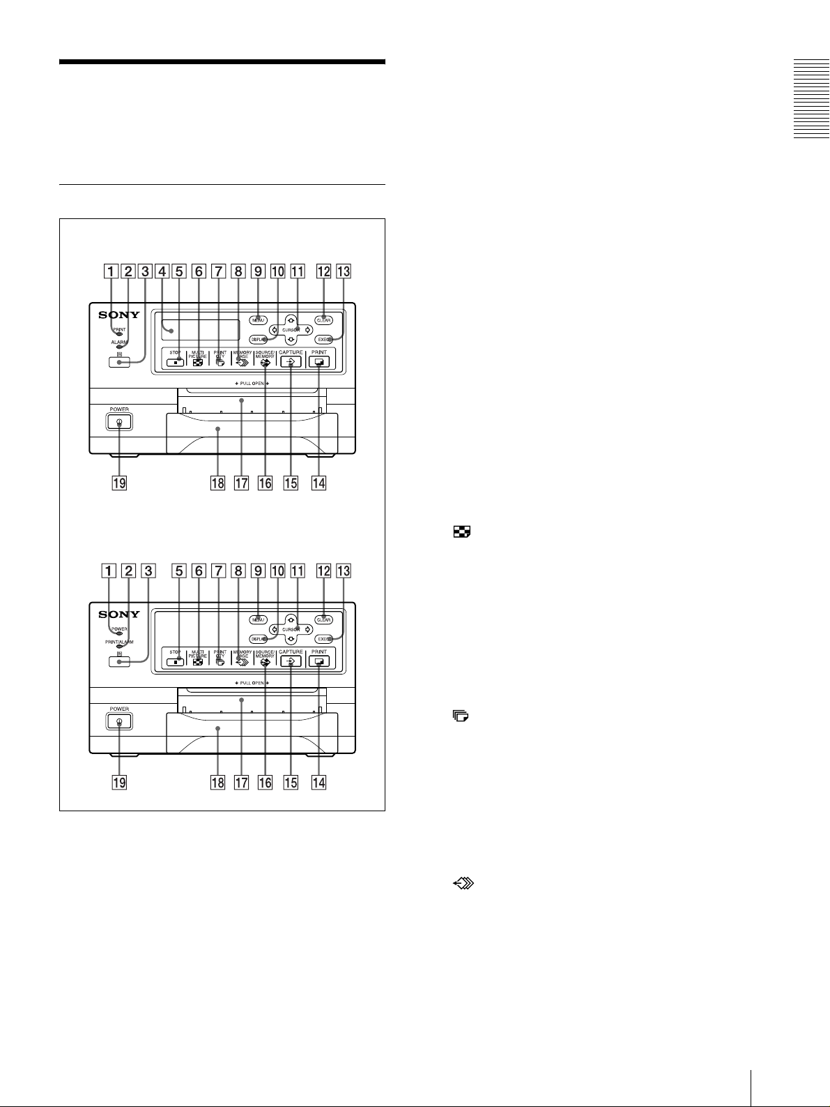
Front Panel
PRINT/ALARM indicator (for the UP-20) (61)
Lights while the printer is printing in green.
Lights in orange when the ink ribbon or paper is
exhausted, the paper jams, or another problem
occurs.
Introduction
C Remote sensor (12)
Aim the head of the remo te contro l unit to wa rd this
sensor.
UP-21MD
UP-20
D Printer window display (only for the UP-21MD)
Displays messages that also appear along the
bottom edge of the monitor screen. The printer
window display has a narrower display range and
shows only a limited number of characters. Also
displays the menu screen line at which the cursor is
positioned. If an error occurs, a corresponding error
message is displayed.
The contrast of the printer window display can be
adjusted on the SYSTEM SETUP menu.
(“Adjusting the Brightness of the Printer Window
Display (Only for the UP-21MD)” on page 53.)
E STOP button (18)
Press this button to stop continuous printing. The
printer stops printing after finishing the printing
item currently being printed.
F MULTI PICTURE button (25)
Press this button to select the desired printout type
on the regular screen. When you press this button,
the currently selected printout type is displayed for
a few seconds. Each time yo u press this b utton, the
type is switched in the following sequence: 1, 2, 4,
1....
The setting of MULTI PIX on the LAYOUT
SETUP menu changes linked with the press of this
button.
A PRINT indicator (for the UP-21MD)
Lights while the printer is pri nting.
POWER indicator (for the UP-20)
Lights in green while the printer power is on.
B ALARM indicator (for the UP-21MD)(61)
Lights in orange when the ink ribbon or paper is
exhausted, the paper jams, or another problem
occurs.
G PRINT QTY (quantity) button (20)
Press this button to set the nu mber of copies on t he
regular screen. You can set any number up to 9.
When you press this button, the currently selected
number is displayed for a few seconds. The setting
of PRT QTY on the PRINTER SETUP menu
changes linked with the press of this button. You
can change the number even when the printer is
printing.
H MEMORY PAGE button (22, 25, 36)
Press to select the memory page.
I MENU button
Press this button to display or clear the menus.
Location and Function of Parts and Controls
5
Page 6
Introduction
J DISPLAY button (19, 36)
When the regular screen is displayed, pressi ng this
button toggles the screen d isp lay o f messag es such
as Q1, A, etc., on and off regardl ess of the setting of
the DISPLA Y item in the OUTPUT SETUP menu.
The setting of DISPLA Y in the OUTPUT SETUP
menu changes linked with the press of this button.
When the menu is displayed, pressing this button
temporarily clea r s the menu display. While this
button is held down, the menu display disappears.
K Cursor keys
Use to select a desired item from the menu.
Also, these keys are used to position the cursor
(green pointer) on the regular screen when
capturing multiple reduced images.
L CLEAR button (35, 36)
Press this button to clear the images capt ured in the
memory pages. Which images can be cleared with
the CLEAR button depends on the setting made
with the FUNCTION SETUP menu.
When the clear function of this b utton is set to OFF,
the buzzer sounds if you press the CLEAR button.
block this output slot . Doing so may cause the paper
to jam.
R Paper tray (9, 15)
Load paper into this tray.
S ! POWER switch
Press this switch to turn the printer on or off.
Rear Panel
UP-21MD
M EXEC button
Press this button to execute the values set with the
COLOR ADJUST menu o r to lo ad a u ser set in the
PRINTER SETUP menu and to re gister the user set
in the SYSTE M S ET U P menu. Also, thi s button i s
used to enter the characters of a caption in the
CAPTION menu.
N PRINT button
Press this button to make a printout.
O CAPTURE button
Press this button to capture an image in a memory
page.
P SOURCE/MEMORY button
Press this button to select which signal is to be
output to the monitor.
The memory image and source image are toggled
each time you press this button.
Q Paper output slot
Printed pages (printouts) are ejected here.
Depending on the curle d condition o f printout s, the
printer may stop printing and display the message
“REMOVE PRINTS.” In such a case, remove the
printouts accumulated on the paper tray. The printer
will start to print the remaining copies
automatically. When the UPC-21L printing pack is
used, the ejected printouts are accumulated on the
paper tray, but protruding from the tray. Do not
UP-20
6
Location and Function of Parts and Controls
Page 7
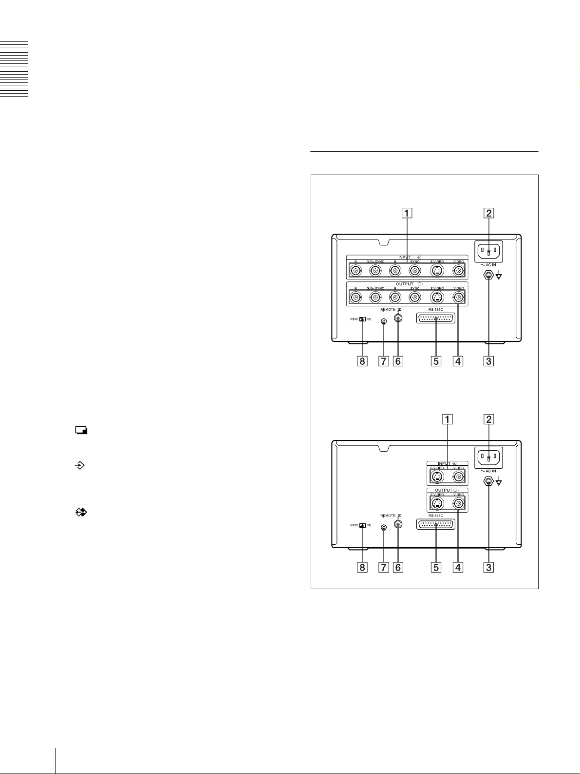
A t INPUT (input signal) connectors (10)
Used to connect th e video equipment supplying the
source image.
Connector Connecta ble equipm ent
RGB SYNC
S VIDEO Vi deo equipment with a Y/C
VIDEO Video equipment with a
a) RGB SYNC connectors are equipped only with the UP-
21MD.
a)
Video equipment with RGB
SYNC output connectors
separated outp ut co nn e ct or
composite video signal output
connector
B - AC IN connector (10, 11, 12)
Used to connect th e print er to a w all outlet wit h the
supplied power cord.
C Equipotential gr ound terminal conn ector (10,
11, 12)
Used to connect to the equipotential pl ug to bring
the various parts of a system to the same potential.
Refer to “Important safeguards/notices for use in
the medical environments” on page 2.
H NTSC/PAL (NTSC/PAL TV) selector (10, 11)
Set this selector according to the TV system of the
input signal. If you change this setting, turn the
printer power off, then back on again.
Selector position When
NTSC NTSC system video equipment is
connected.
PAL PAL system video equipmen t is
connected.
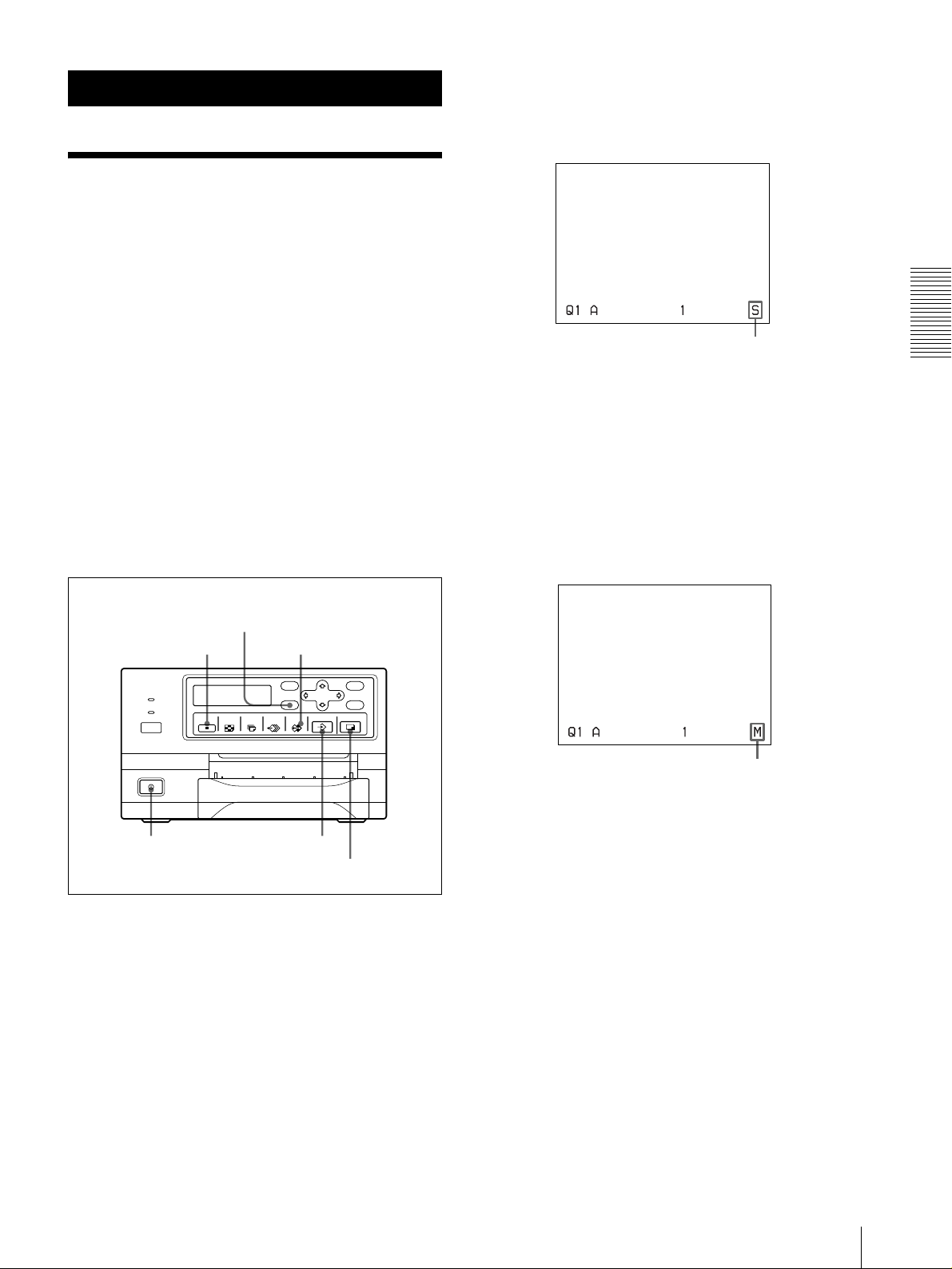
Monitor Display
When the printer is connected to the video mon it or and
you first turn on the printer, the following regular screen
message appears.
When the MENU button is pressed, the menu screen
displayed.
For detailed information on the menu screen, see “Menu
Tree” on page 39.
Introduction
D T OUTPUT connectors (11)
Used to connect the video monitor.
Refer to “Important safeguards/notices for use in
the medical environments” on page 2.
Connector Connecta ble equipm ent
RGB SYNC
S VIDEO Video monitor with a Y/C
VIDEO Video monitor with a composite
b) RGB SYNC connectors are equipped only with the UP-
21MD.
b)
Video monitor with RGB SYNC
input connectors
separated input connector
video signal input connector
E RS-232C connector (12)
Used to connect a computer to control the printer.
For details, contact your nearest Sony dealer.
F REMOTE 2 connector (stereo mini jack) (12)
Used to connect a RM-91 Remot e Control Unit (not
supplied).
G REMOTE 1 connector (special mini jack) (12)
Used to connect an RM-5500 Remote Control Unit
(not supplied) to be used as a wired remote control
unit.
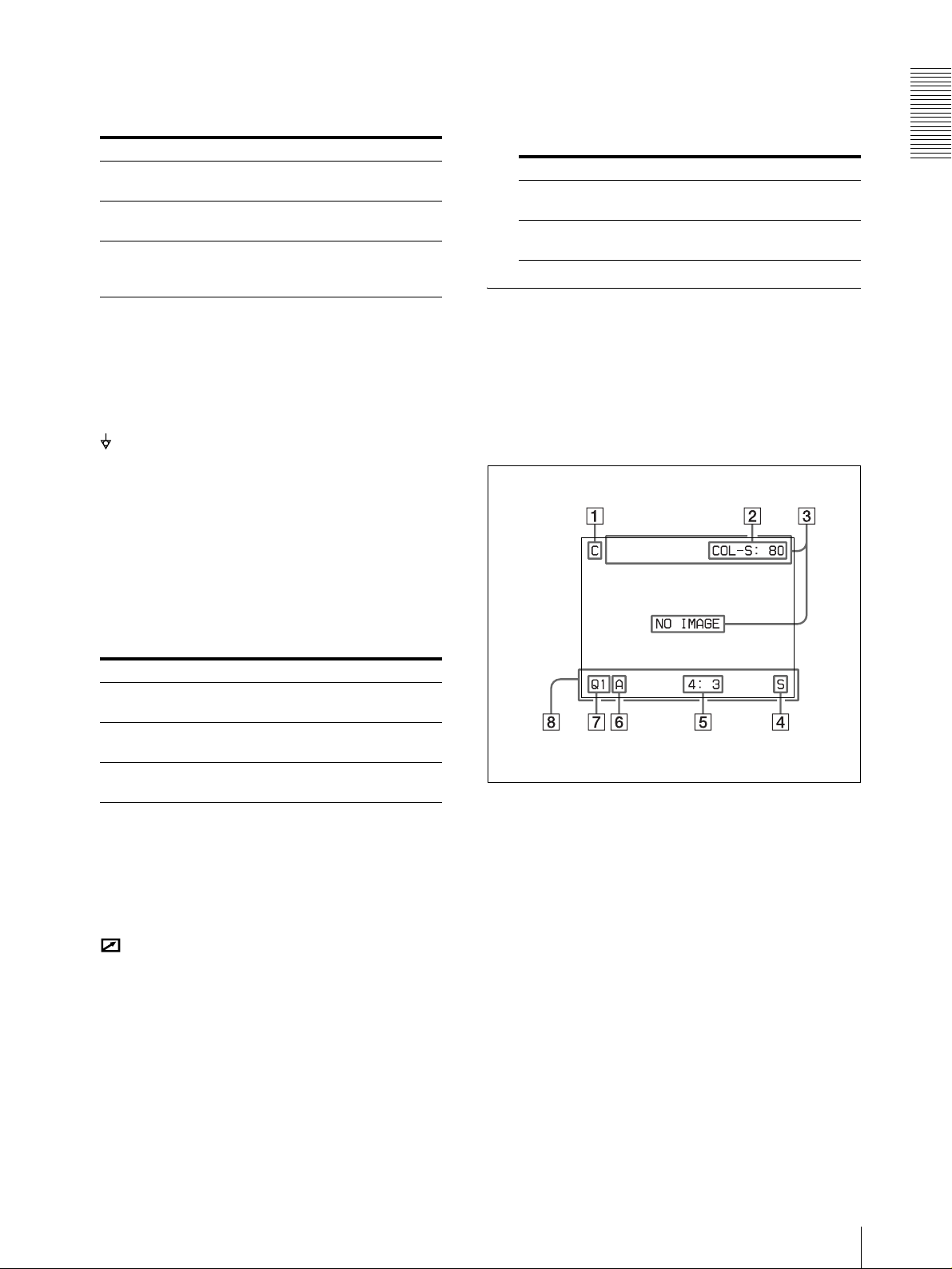
A C (Caption) display section
C is displayed in white when the printer is set to
print a caption.
B Ink ribbon type and remaining amount of ink
ribbon display sec tion
Displays the ink ribbon type and the remaining
amount of ribbon (indicat es the number of printouts
that can still be made with the ribbon) when the
ribbon remaining display function is set to ON.
C Message display section
Messages are displayed.
Error messages are displayed on t he t op li ne o f th e
screen.
Warning messages are displayed on the center of
the screen.
Location and Function of Parts and Controls
7
Page 8
Introduction
D S or M (image type) display section
Indicates the type of image being displayed on the
monitor screen.
S (Source): The image from the input signal
source is displayed on the screen.
M (Memory):The image captured in memory is
displayed on the screen.
E Printer operation mode display section
Indicates the printer operation mode (type of
printouts such as multiple reduced images).
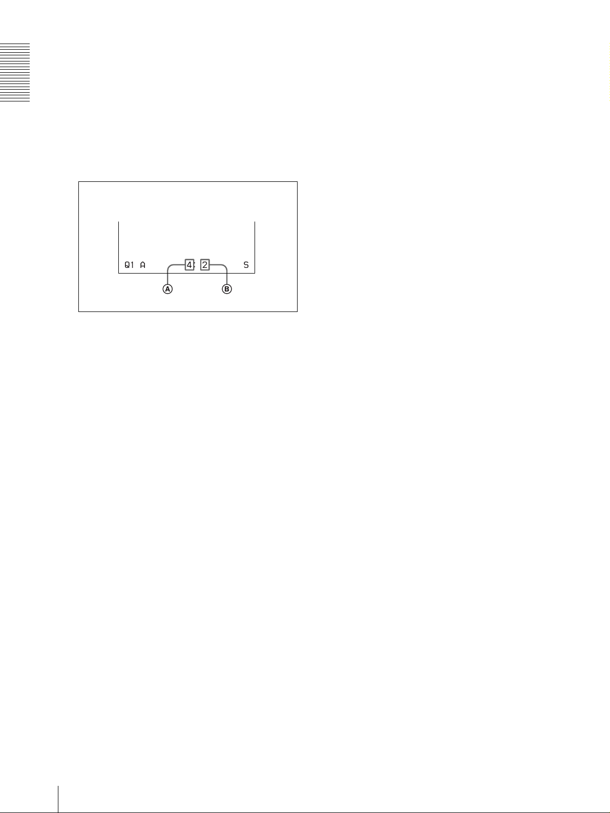
Position of the cursor:
2nd position of four reduced images
A Type of printout
Indicates the type of printout.
When SEP ARA TE (image with white borders)
is set to ON on the LA YOUT SETUP menu, F
is attached to the number in this position.
B Position of the cursor
Indicates the position where the cursor is
currently placed and where an image will be
captured.
F Memory page display section
Indicates the currently selected memory page.
While the image in the memory page is being
printed, the memory page indication blinks in
white. The memory page whose memory image is
queued to be printed blinks in white.
G Q (print quantity) display
Indicates the number of copies to be printed. This
item blinks while the printer is busy.
H Printer setting status display section
The corresponding currently selected status is
displayed when either MUL TI PICTURE or PRINT
QTY button is pressed.
8
Location and Function of Parts and Controls
Page 9
Preparation
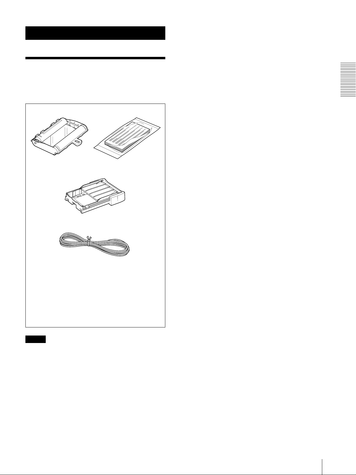
Supplied Accessories
The printer is packed together with the following
accessories. Check that nothing is missing from your
package.
Ink ribbon and paper a) (1)
Paper tray (1)
Preparation
Power cord (1)
Warranty card (1) (for the customers in the U.S.A and Canada
only)
CD-ROM (1) (for the customers in the Europe only)
Thermal head cleaning cartridge (1)
Instructions For Use (1)
a) Use the ink ribbon and paper for an operation check.
Notes
• Retain the original carton and packing materials in
case you have to transport the unit in the future.
• Remo v e the ink ribbon cart ridg e and paper tray when
transporting the printer.
• When transporting the printer, secure the thermal
head. (For detailed information on how to secure it,
see page 56.)
Supplied Accessories
9
Page 10
Connections
Preparation
To enable printing, video equipment to act as an input
signal source, and a video monitor to di spl ay i mages or
menus must be connected.
The following diagrams illu strate how to make the input ,
output and remote control connections. Use this as a
guide when connecting the cables required to transmit
signals to and from the equipment to be used fo r
printing.
Notes
• Turn off the po wer of each de vice before attempting to
make any connections.
• Connect the AC power cord last.
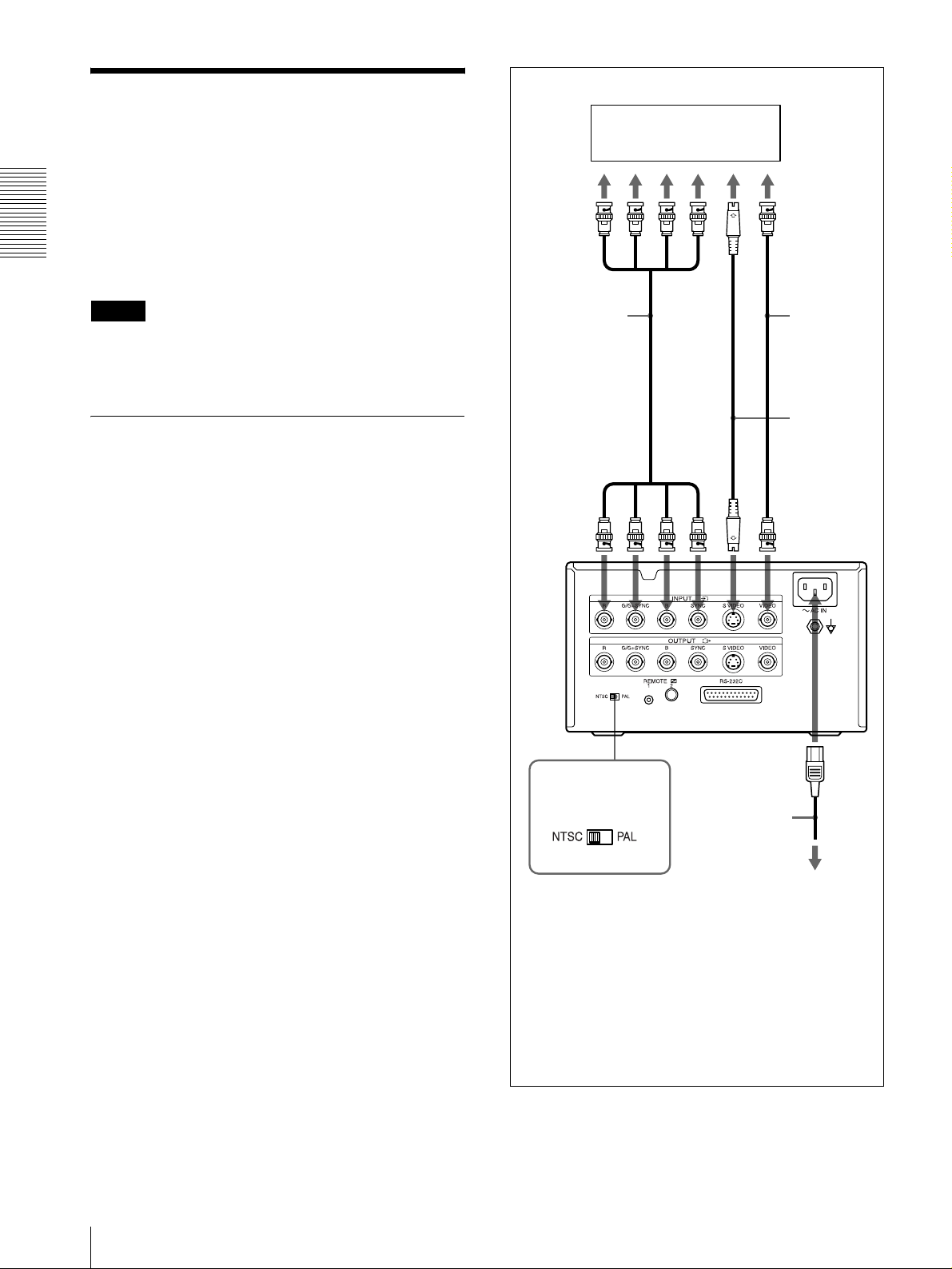
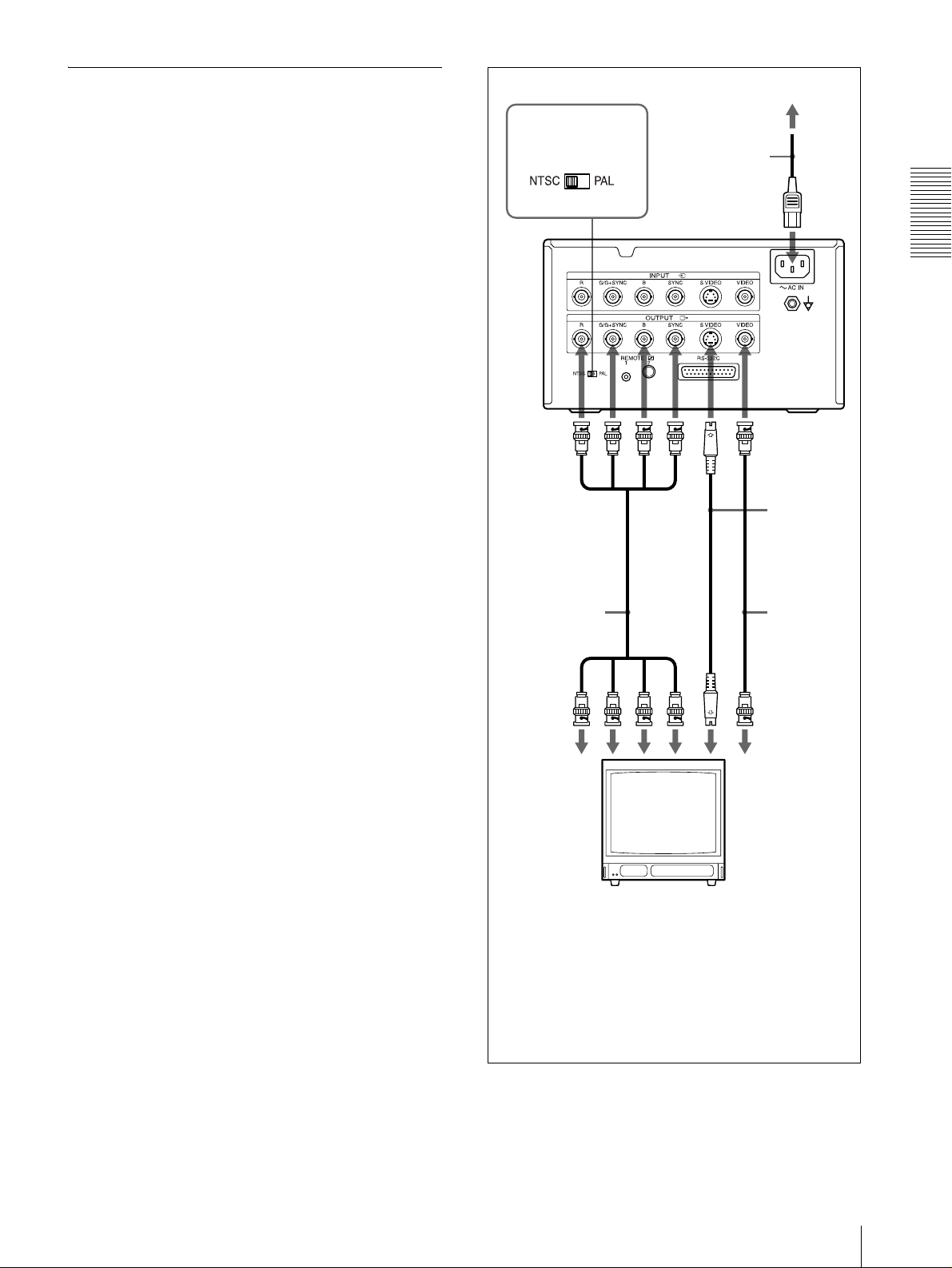
Connecting Video Equipment
Connect the video equipment providing the video
images to be printed.
Connect the video equipment which will be used in
actual printing, using the following diagram as a guide.
Before connecting the video equi pment, see “Important
safeguards/notices for use in the medical en vironments”
on page 2.
to RGB
output
connectors
75-ohm
coaxial cable
with BNC
connectors
to RGB SYNC
INPUT
UP-21MD
Video equipment
to S VIDEO
output
connector
b)
VIDEO
INPUT
to S
to composite
video output
connector
75-ohm
coaxial cable
with BNC
connectors
Connecting
cable (with
DIN 4-pin
connectors)
to VIDEO
INPUT
to AC IN
NTSC/PAL selector
a) Set the NTSC/PAL selector to match your TV system. To
switch the TV system, turn the power off once, then change
the setting. If you change the setting with the power on, this
mode will not be switched.
b) Only for the UP-21MD.
a)
AC po wer cord
(supplied)
to wall outlet
10
Connections
Page 11
Connecting the Video M onitor
Connect a video monitor t o view capt ured images and to
check those to be printed. Connect a suitable video
monitor which will be used in actual printing, using th e
following diagram as a guide.
Before connecting the vi deo equipment , see “Important
safeguards/notices for use i n the medical en vironmen ts”
on page 2.
NTSC/PAL selector
to wall outlet
a)
AC po wer cord
(supplied)
to AC IN
When connectin g the v ideo mo nitor only t o the
RGB OUTPUT connectors (only for the UP21MD)
When connecting the video monitor only to the RGB
OUTPUT connector without connecting to SYNC
connector, set SYNC ON G in the OUTPUT SETUP
menu to ON.
UP-21MD
to RGB SYNC
OUTPUT
75-ohm coaxial
cable with B NC
connectors
to RGB input
connectors
Preparation
to VIDEO
INPUT
Connecting
cable (with
b)
to S VIDEO
OUTPUT
to S VIDEO
input
connector
DIN 4-pin
connectors)
75-ohm
coaxial cable
with BNC
connectors
to composite
video input
connector
Video monitor
a) Set the NTSC/PA L selector to match your TV system. To
switch the TV system, turn the power off once, then change
the setting. If you change the setting with the power on, this
mode will not be switched.
“When connecting the video monitor only to the RGB
b) See
OUTPUT connectors (only for the UP-21MD)”.
Connections
11
Page 12
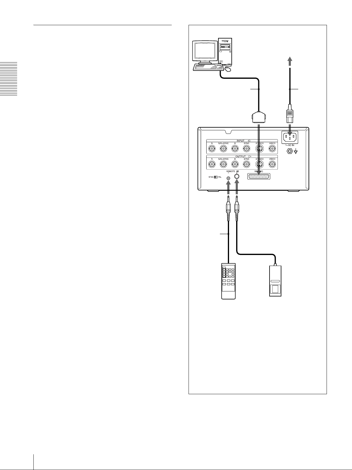
Making Connections to Enable Remote Control
Computer
a)
Preparation
The printer can be controlled remotely by connecti ng an
RM-5500 Remote Control Unit (not supplied), an RM91 Remote Control Unit (not supplied), or a personal
computer.
RS-232C cable
UP-21MD
to REMOTE 1 to REMOTE 2
Remote
control
connecting
cable
(supplied
with the RM-
5500)
to wall outlet
AC power
cord
(supplied)
to AC IN
12
Connections
b)
(not supplied)
a) When connecting a personal computer, select the
appropriate baud rate from the SYSTEM SETUP menu.
(See “Setting the Baud Rate” on page 54.)
b) You can also use the remote control unit as a wireless unit.
In such a case, aim the head of the remote control unit at the
remote sensor on the printer. With fresh batteries, the range
of the remote control unit is about 3 meters.
RM-91 (not supplied) RM-5500
Page 13
Before Printing
Before printing, but after mounting the paper tray on the
printer and making the necessary connections (see
“Connections” on page 10), perform the following as
preparation.
• Loading an ink ribbon (See below.)
• Loading paper (See page 14.)
• Selecting the input signal (See page 15.)
Notes
• Use the ink ribbon and paper contained in the same
package as a pair. Before attempting to load an ink
ribbon or paper , make sure that the combinati on of the
ink ribbon and paper is compatible.
• When either an ink ribbon or paper has been
exhausted, replace bot h the ink ribbon and paper at the
same time.
• Use only ink ribbon and paper designed for use with
this printer. Failing to do so is likely to result in
malfunctions. (See“Recommended Ink Ribbon and
Paper” on page 57.)
printer. The correct amount of ink ribbon
remaining is not disp layed when the ink ribbon
and paper supplied are loaded.
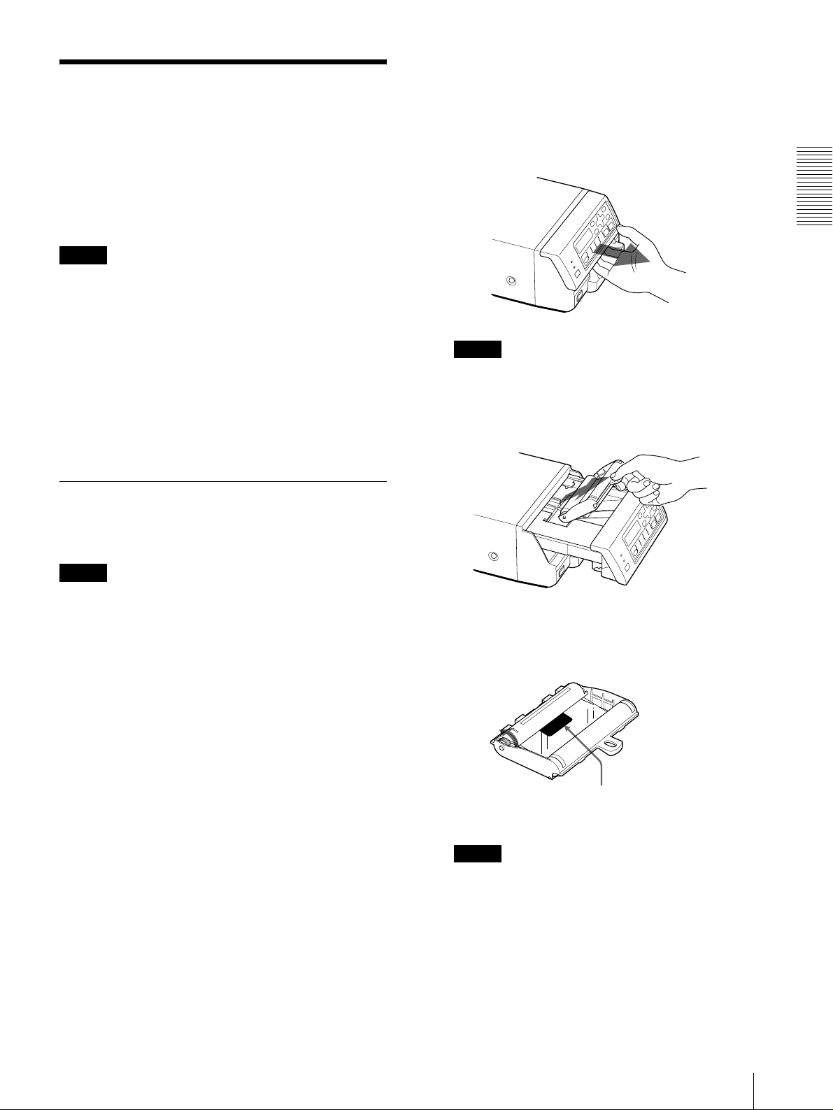
1
Open the front panel by pulling the front panel
toward you.
Note
Be sure not to open the front panel when printing.
2
Remove the spent ink ribbon when replacing the
ink ribbon.
Preparation
Loading an Ink Ribbon
Load an ink ribbon into the printer’s ink ribbon
compartment.
Notes
• When you use the printer for the first time, the
thermal head is still secured in place. Before
attempting to load the ink ribbon, turn on the
power while the front panel is closed so that the
thermal head is released.
• When loading or re pl aci ng t he in k r i bbon , t ur ni ng off
the power will cause the image stored in the memory
to be lost.
• If a blank sheet of paper is ejected, and the message
RIBBON END appears, the ink ribbon has been
exhausted. Replace the paper together with the ink
ribbon. Do not reuse the ejected blank paper.
• When paper runs out and “0” is displayed as the
amount of ink ribbon remain ing, load a new ink ribb on
and paper at the same time.
• If you load an ink ribbon that is partially used, the
correct amount of ink ribbon remaining will not be
displayed.
• Once an ink ribbon has been completely used up,
replace it. An ink ribbon is not reusable.
• Do not rewind the ink ribbon for reuse.
• Do not touch the ink ribbon or place it in a dusty
location. Finger prints or dust on the ink ribbon will
result in imperfect printing or malfuncti on of the head.
• Use the ink ribbon and paper supplied with the
printer for the initial operation check of the
3
Remove any slack from the ink ribbon.
Wind the spools in the direction of the a rrow until
the start position marker app ears as illustrated.
Start position marker
Note
If the ribbon is l ef t slack, it may be damaged when
inserted.
Before Printing
13
Page 14
Preparation
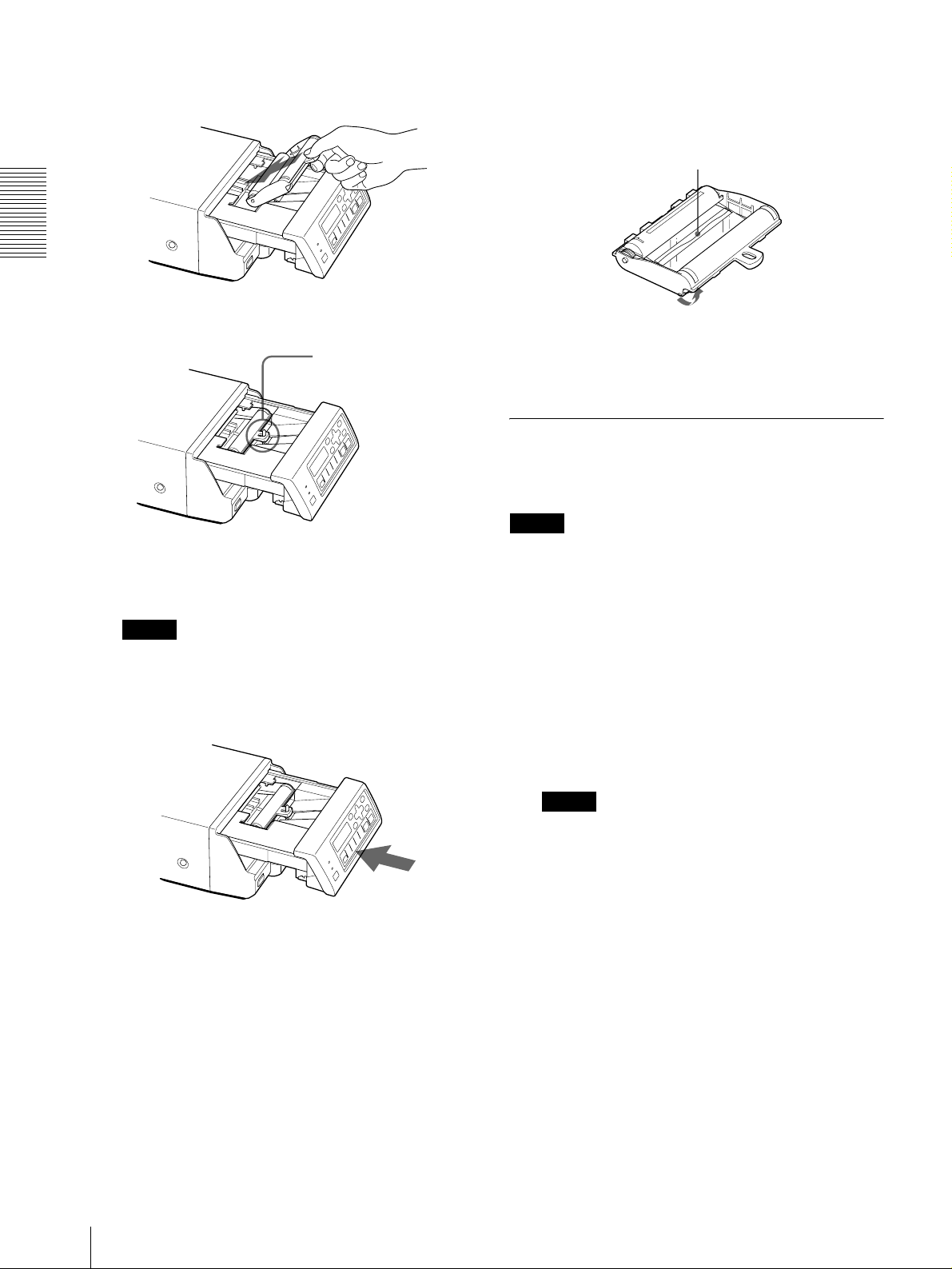
4
Load the new ink ribbon into the ink ribbon
compartment.
If your ink ribbon should tear
Repair the tear with transparent tape. There should be no
problem with using the remaini ng p ort ion of the ribbon.
Transparent tape
Insert the hole of the
handle of the ink ribbon
over the protruberance
of the printer.
5
Close the front panel by pushing the point marked
with “PULL OPEN”.
Note
Be sure to close the front panel completely. If you
do not, a paper jam or a malfunction may occur
while you are printing or cleaning the internal
thermal head.
Turn the spools in the direction of the arrow to
remove any slack until the transparent tape
cannot be seen.
Loading Paper
To load paper on the paper tray, follow the procedure
below. Be careful not to touch the printing surface.
Note
Use only paper recommended. F ailing to do so is likely
to result in malfunctions such as paper jams. (See
“Recommended Ink Ribbon and Paper” on page 57.)
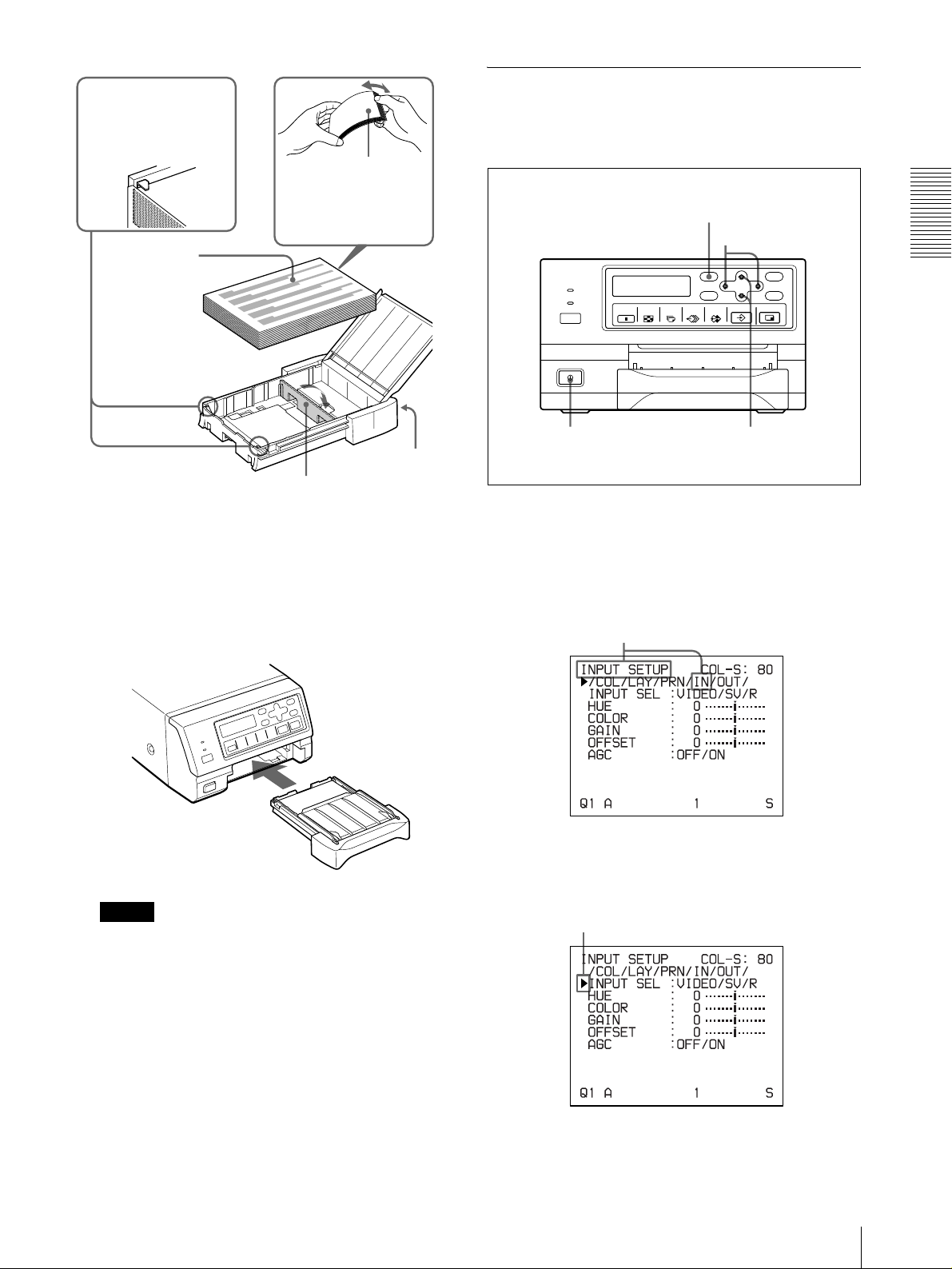
1
T ake ou t the paper tray. Then, open the cover of the
paper tray and place the paper in the paper tray so
that the printing surface f aces up with the protection
sheet on top.
When the UPC-21L printing pack is used: Lay
the partition down.
When the UPC-21S prin ting pack is used: Raise
the partition.
Push the point marked
with “PULL OPEN”.
When storing ink ribbon cartridge:
• Avoid placing the ink ribbon in a location subject to:
– high temperatures
– high humidity
– excessive dust
– direct sunlight
• Store a partially used ink ribbon in its original
packaging.
14
Before Printing
Notes
• The paper tray holds up to 50 sheets of paper
when the UPC-21L printing pack is used and 80
sheets of paper when the UPC-21S p rinti ng pack
is used.
• When handling the paper, do not touch the
printing surface. Dust or f inger prints are likely to
cause unsatisfactory printing or malfunction of
the head. Grasp the paper by the pri nting surf ace
protection sheet.
• When loading the paper, load the paper so that it
lays flat in the paper tray. If the paper is curled, it
will overflow from the paper tray and paper may
not be fed properly. Be sure to riffle the paper
along with the protection sheets before
attempting to place the paper in the paper tray.
• Do not place different types of paper in t he tray at
the same time.
Page 15
Set the paper securely
under the tab.
Place the paper
along with the
protection sheet
in the paper tray
with the printing
surface facing
up.
Selecting the Input Signal
Before printing, select the appropriate input signal (the
input connector to which t he signal to be pri nted is being
input) VIDEO, S VIDEO, or RGB.
Riffle the paper with
the protection sheet.
2, 5
2, 4, 5
Preparation
Partition
2
Remove the protection sheet placed on the top of
the paper.
3
Close the cover of the paper tray, and then slide the
paper tray back into the printer until it clicks into
place.
Note
When you cannot slide the p aper tr ay back int o the
printer , check whether or not paper or pr intout s are
left around the paper outlet slot. Remove them if
there are.
Front
1
1
Turn on the video monitor and th e printer.
2
Press the MENU button and display the INPUT
SETUP menu by pressing the F, f, G or g button.
Switch IN to green by pressing the F, f, G or g button,
then the INPUT SETUP menu appears.
3
Select INPUT SEL by pressing the F or f button.
Position the cursor at INPUT SEL by
pressing the F or f button.
2, 3
When storing the paper
• Avoid storing the paper in a location subject to:
– high temperatures
– high humidity
– excessive dust
– direct sunlight
• Use the original package for storing unused paper.
Before Printing
15
Page 16
Preparation
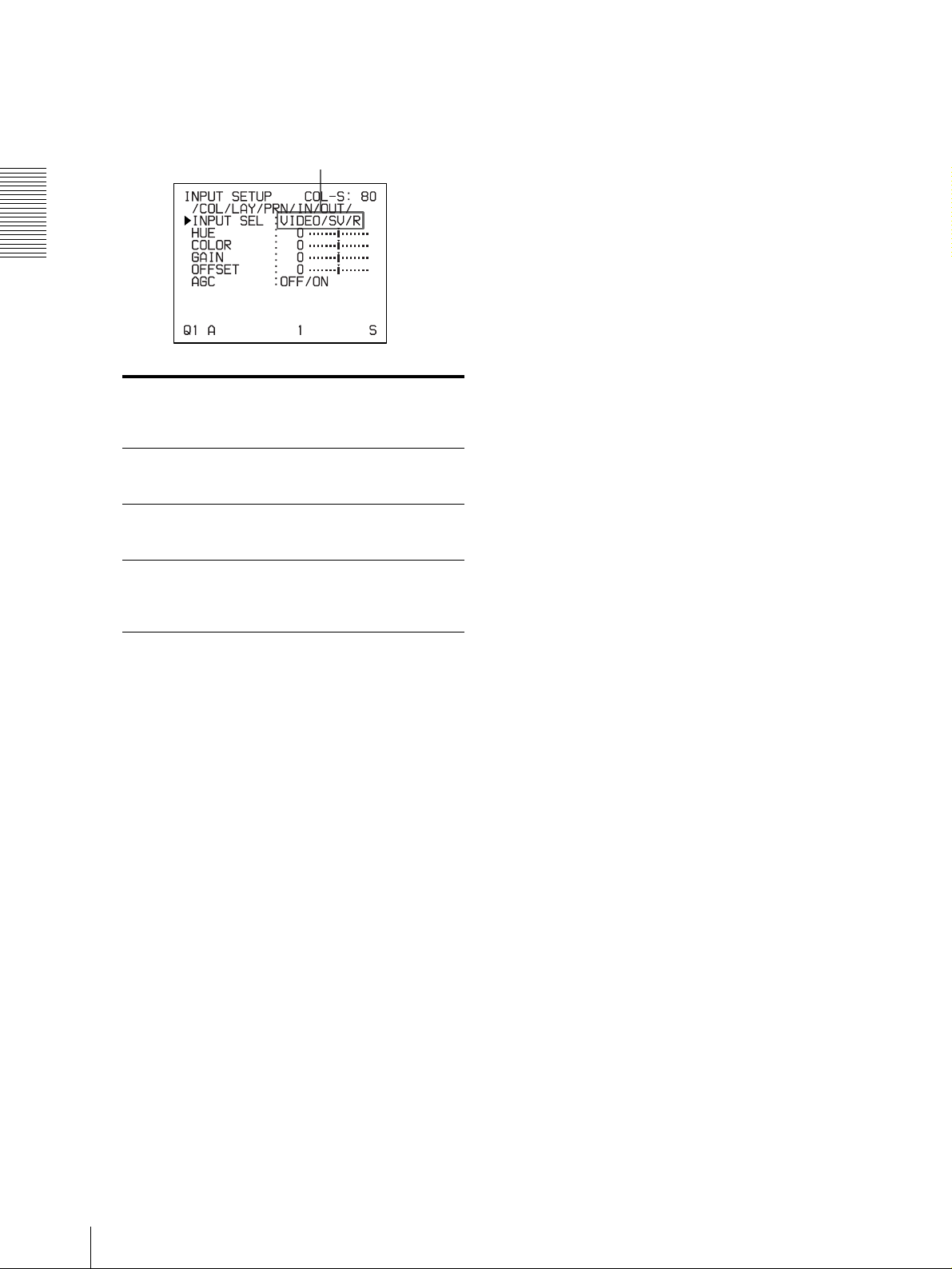
4
Select the desired i nput sig nal b y p r essin g t he G or
g button.
Switch the desired input signal to green by
pressing the G or g button. The selected
input signal turns green and is spelled out.
Source signal of the
image to be printed
Signal from video
equipment connected to the
VIDEO INPUT connector
Signal from video
equipment connected to the
S VIDEO INPUT connector
Signal from video
equipment connected to the
RGB SYNC INPUT
connectors
a) The RGB SYNC INPUT connector s are equipped only
with the UP-21MD.
When RGB is selected, ** ** ** is disp la ye d at the
selections of items HUE and COLOR on the INPUT
SETUP menu.
5
Press the MENU button.
Video monitor and
printer window display
(the selected input
signal is spelled out)
V tVIDEO
SV t S VIDEO
R t RGB
a)
The regular screen appears.
16
Before Printing
Page 17
Operation
Making Full-Size Image Printouts
This section explains how to make a full-size image
printout. The operations described here constitute the
basic procedure for making a printout.
2
Start the video sourc e to display the source image
on the video monitor.
This operation is done using the controls of the
video equipment acting as the source.
Before making a full-size image printout
• All connections should have already been made. (See
page 10.)
• Ensure that the appropriate ink ribbon/paper set is
being used and that they are correctly loaded. (See
pages 13, 14 and 57.)
• Select the input signal to be used to make a printout.
(See page 15.)
• Set the printer to capture one full-size image into
memory. (See page 26.)
• S elect the appropriate memory page. (See page 24.)
• Confirm the printout color qu ality (using, for e xample,
the LOAD COLOR number). (See page 45.)
DISPLAY button
SOURCE MEMORY buttonSTOP button
Shows that an image from the source equipment is
currently displayed on the screen.
3
Press the CAPTURE button at the instant the image
you want to print appears on the screen.
The image is captured into memory. The memory
image is displayed on the screen. Which image
appears after this, the source image or the memory
image, depends on the setting made with the
FUNCTION SETUP facility of the printer. (See
page 27.)
Shows that an image captured in memory is
displayed on the monitor.
Operation
1
1
Turn on the video monito r and the printer.
3
4
If the captured image is blurred
A quickly moving image may be blurred when
captured. Should this occur, change the memory
mode setting to FIELD, then print it again.
Although the blur should be eliminated, the
ultimate print qua lity will be slightly degraded.
Select the FIELD mode on the LAYOUT SETUP
menu. (See “Selecting the memory mode” on page
24.)
Making Full-Size Image Printouts
17
Page 18

Operation
Note
Usually , it is recommended that you make printouts
in FRAME mode.
You can confirm the memory mode setting on the
bottom part of the video monitor screen.
When FRAME mode is selected:
The printing time depe nds on the ty pe of paper and
printer settings.
On the video monitor, Q display blinks in the color which
is being printed.
The color changes as follows during printing:
Start t yellow t magenta t cyan t finish
On the printer window display (only for the UP-21MD),
the color indication changes as the color printing
precedes:
Start t YELLOW t MAGENTA t CYAN t finish
When FIELD mode is selected:
To change the image captured in memory
1 To display the source image when the memory
image is displayed on the screen, press the
SOURCE/MEMORY button.
2 Press the CAPTURE button at the instan t the
image you want to print appears.
The previous image is replaced with the new
one.
4
Press the PRINT button.
The printout pops out on the paper tray.
Notes
• Do not turn off the power during printing.
If you do so, pap er may not be ejected and may jam in
the printer.
• Do not leave more than 10 sheets of printouts on the
paper tray. Doing so may cause a paper jam. Even if
fewer than 10 sheets of printouts have been
accumulated on the paper tray, the printer may stop
printing for various reasons and the message
“REMOVE PRINTS” appea rs. In such a case, remo ve
printouts accumulated on the paper tray. The printer
will start to print automatically.
• You can not change the printer application mode or
settings using the WINDOW SETUP menu during
printing.
To stop printing
• When you make one printout, you can not stop
printing midway. Wait unt il a printo ut pops out on the
paper tray.
• When you make multiple copies, press the STOP
button. (For detailed information on setting the print
quantity, see “Making Multiple Copies of Identical
Printouts” on page 20.) The printer stops printing
when the page currently printing is completed. Also,
any printing job queued are cancelled.
18
Making Full-Size Image Printouts
If the printer does not print
The printer will fail to prin t in the following cases:
• While an error message is displayed on the video
monitor screen and printer window display.
Page 19
– Proceed as described in “Error/Warning Messages”
on page 61.
• When an image has not been stored in memory.
– Image data stored in memory is lost if you turn off
the power. Capture the image into memory again,
then press the PRINT button. If no image is stored
in memory, the printer will not print even if you
press the PRINT button.
To make a printout at high speed
You can select the speed using t he PRN SPEE D item on
the PRINTER SETUP menu.
When you want to PRN SPEED
Make a printout at normal speed. NORMAL
Make a printout at high speed. HIGH
For detailed information on how to operate the menu,
see “Basic Menu Operations” on page 40.
• Do not stick tape on a printout. Also, avoid leaving a
plastic eraser on a printout or placing a printout in
contact with materials which contain plasticizer
(under a desk mat, for example).
• Do not allow alcohol or other volatil e organi c solvents
to come into contact with the printouts.
Making Printouts with the Desired User Set Number
Y ou can register all the printer settings as a user settings.
The printer allows you to register three sets of settings as
User Set 1, 2 and 3. (See “Registering a User Set” on
page 54.) By selecting a desired user set number, the
printer functions according to the corresponding
settings. You can change a part of the selected user
settings and make printouts.
Note
Operation
When you want to see an image that is hidden
below a screen message
You can erase screen messages (such as Q1, A and so
on) from the video monitor screen by pressing the
DISPLAY button. The screen message disappears. To
display a screen message, press the DISPLAY button
again. (See “Erasing the Screen Display on the Video
Monitor” on page 36.) You can also erase the
information about ink ribbon and paper. (See
“Displaying the Type and Remaining Amount of the Ink
Ribbon” on page 54.)
If a black line appears on the printout
Sometimes, a black line appears on the printout,
although it does not appear on the video monitor. This
black line can be eliminated from the printout. (See
“When a Black Frame or Lines Show up on the
Printouts” on page 47.)
If the color quality of the printouts is not
satisfactory
Y ou can obtain satisfa ctory color qualit y of the printout s
by compensating for the input signal and/or adjusting
the color quality of the printouts. (See “Compensating
for the Input Signals” on page 43 and “Adjusting the
Printout Color” on page 45.)
When you load a new ink ribbon and paper, the color
balance may change due to differences caused by the
new pair of ink ribbon and paper in the new printing
pack. It is recommended that you adjust the color
balance each time you load a new ink ribbon a nd paper.
(“Adjusting the Color Balance” on page 48.)
If you change the currently selected user set to another
one, the image stored in memory pages will be cleared.
Be sure to change the LOAD USER number before
capturing the image.
1, 3
1
1, 2
4
6
5
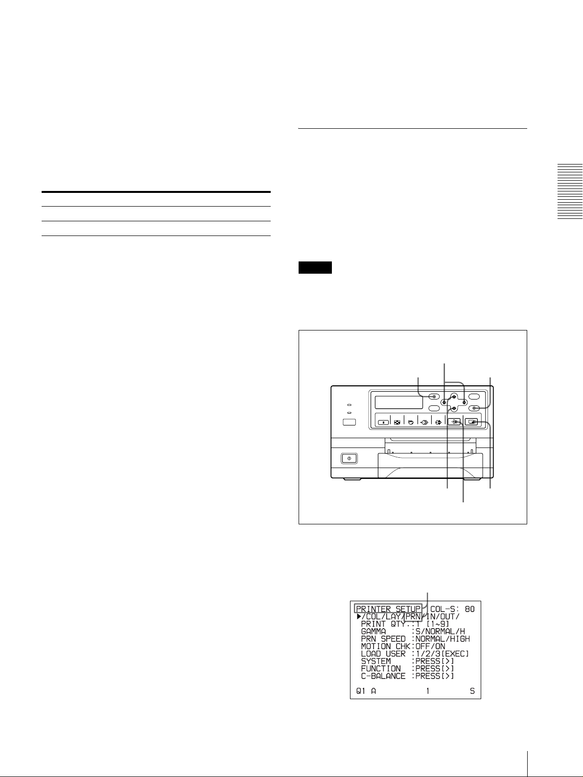
1
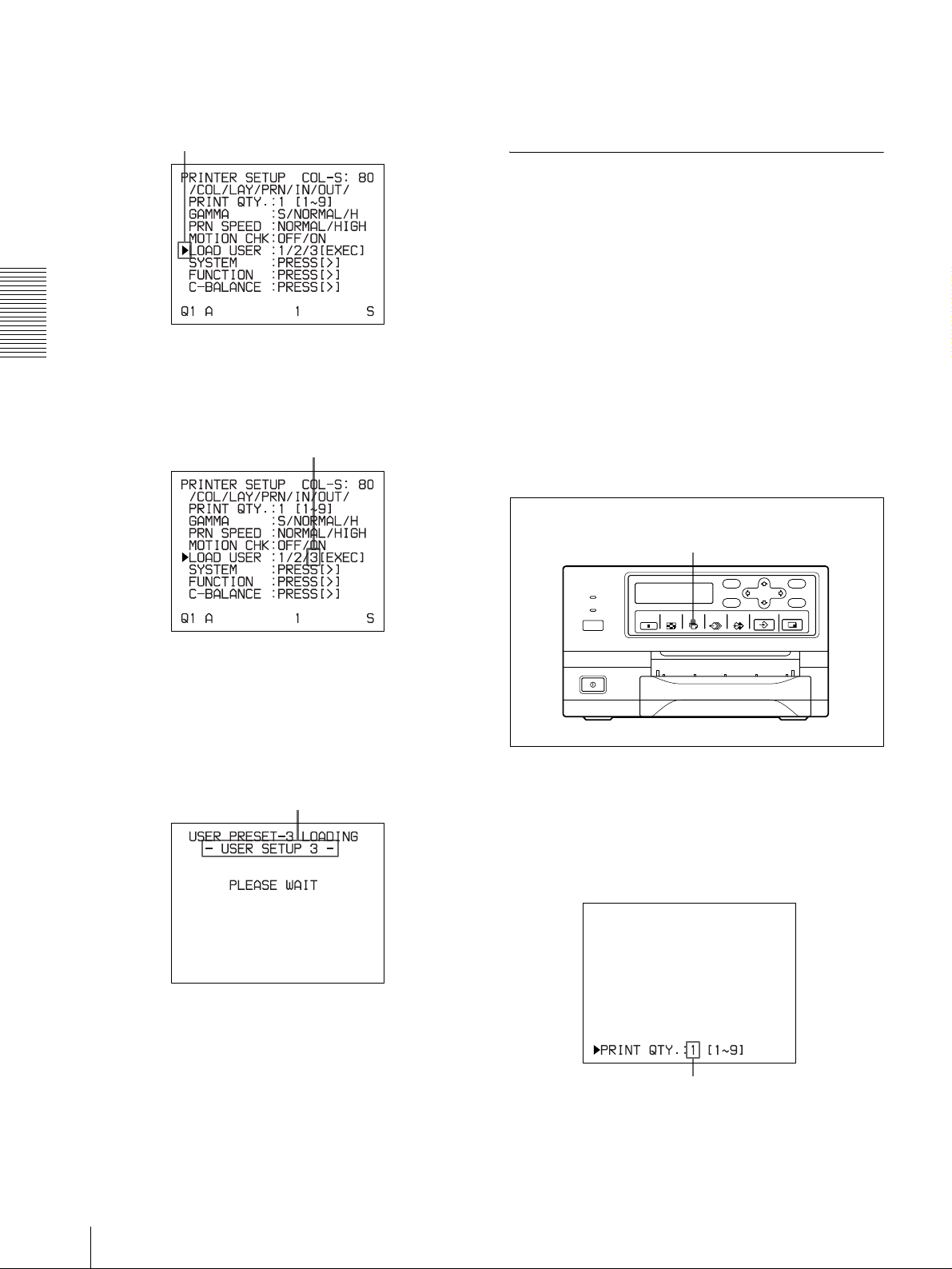
Press the MENU button, and displa y the PRINTER
SETUP menu by pressing the F, f, G or g button.
Switch PRN to green by pressing the F, f, G or g
button, then the PRINTER SETUP menu appears.
When storing your printouts:
• Avoid stor ing the pr intout in a l ocation subj ect to high
temperatures, high humidity, excessive dust or direct
sunlight.
Making Full-Size Image Printouts
19
Page 20
Operation
2
Select LOAD USE R by pressing the F or f button.
Position the cursor at LOAD USER by pressing the
F or f button. The currently selected load user
number is lit in green.
3
Select the desired user number by pressing the G or
g button.
Switch the desired user number to green by
pressing the G or g button.
6
Press the PRINT button.
The printer makes printouts according to the user
set selected in step 3.
Making Multiple Copies of Identical Printouts
You can make up to 9 copies of identical printouts.
Setting the printout quantity
The following two methods are available to set the
number of printouts.
• Using the PRINT QTY button
However, you cannot use this button to decrease the
number of printouts.
•Using the menu
You can change the designated number of copies before
printing or any time during printing.
T o set the printout quantity by using the PRINT
QTY button
4
Press the EXEC button.
The user set selected in step 3 is executed.
While the selected user set is being executed, the
following message appears.
When the user name is registered, the
user name appears.
1, 2
1
Press the PRINT QTY button.
The following screen appears.
If you do not perform any operation after you pr ess
the PRINT QTY button, the currently set number of
copies appears for a few seconds, after which it
disappears.
5
Press the CAPTURE button at the instant the image
you want to print appears on the screen.
The image is captured into memory according to
the user set selected in step 3.
20
Making Full-Size Image Printouts
Currently selected number of copies
Page 21
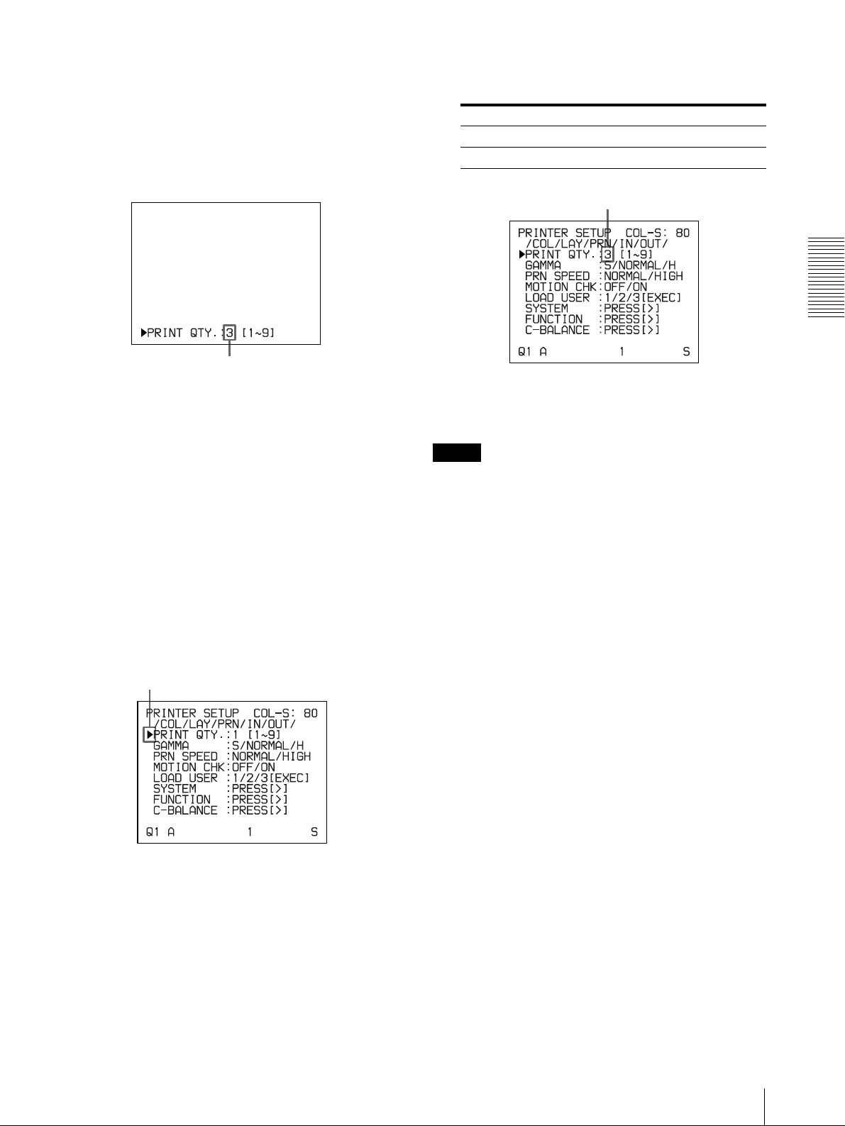
2
Press the PRINT QTY button until the desired
number appears, while the screen which appea rs in
step 1 is displayed.
Repeatedly pressing the PRINT QTY button
increases the number up to a maximum of 9. Or
repeatedly pressing the g button also increases the
number up to a maximum of 9.
Press the PRINT QTY button or g button until the
desired number appears.
To decrease the number of copies
While the screen which appears in step 1 is displayed,
press the G button. Each ti me you press the G b utton, th e
number decreases and stops at 1.
Setting the printout quantity using the menu
1
Display the PRINTER SETUP menu according to
the operations of step 1 described in “Making
Printouts with the Desired User Set Number” on
page 19.
3
Select the desired number o f copies by pressing the
G or g butt on.
When you want to Button
Increase the quantity.
Decrease the quantity. G
Display the desired number of copies by
pressing the G or g button.
4
Press the MENU button.
The regular screen appears.
Note
Do not leave more than 10 sheets of printouts on the
paper tray. Doing so may cause a paper jam. Even if
fewer than 10 sheets of pr intouts hav e been accumulated
on the paper tray, the printer may stop printing for
various reasons and the message “REMOVE PRINTS”
appears. In such a case, remove printouts accumulated
on the paper tray. The printer will start to print
remaining copies automatically.
g
Operation
2
Select PRINT QTY by pressing the F or f button.
Position the cursor at PRINT QTY by pressing the
F or f button.
If the paper runs out during printing
The printer stops the printing operation.
Load the paper into the paper tray and press the P RINT
button.
However, the printout quantity is reset to the o riginal
quantity requested before printing was stopped.
For example, if the printout quantity is set to 5, and the
paper runs out when three copies are printed, the
printout quantity is reset to 5. If you want to print only
the remaining c opies , set the prin tout quant ity to 2 aft er
loading the paper. (See “Loading Paper” on page 14.)
Making Full-Size Image Printouts
21
Page 22

Capturing Another Image While Printing
While the printer is pri nting, you can queue printing jobs
by capturing another image into another memor y page to
be printed once the printer becomes free. The numbe r of
usable memory pages depend on the type of printouts
and settings. (See page “Memory page” on page 24.)
3
Press the PRINT button.
The image captured in step 2 is q ueued. The i mage
is printed as soon as all pre v ious pr int ing jobs h a ve
been completed.
Operation
1
2
3
1
Select the desired memory page by pressing the
MEMORY PAGE button.
Pressing the MEMORY PAGE button switches the
memory page.
Memory page whose image has been queued for
printing (blinks white on the video monitor)
The memory page display returns to white on the video
monitor once printing has been completed.
Note
Another image cannot be stored in a memory page
in which an image has already been queued for
printing (memory page indicat ion bli nks in whit e).
In such a case, the “PRINTING MEMORY”
message appears on the video monitor. For the UP21MD, the “PLEASE WAIT NOW PRINTING”
message also appears in the printer window display .
4
To queue another memory page, repeat steps 1, 2
and 3.
The available memory pages appear in white.
2
Press the CAPTURE button at the instant the image
you want to print appears on the screen.
22
Making Full-Size Image Printouts
Page 23

Making Variations of Printouts
Y o u can capture various kinds of images i n memory and
make variations of printouts using the images captured
in memory.
Frame mode: An image is captured in a memory area.
Printouts with high resolution can be obtained.
Video monitor
Printout of a full-size
image
Printout of two
reduced images
Printout of four
reduced images
Y ou can also make printouts of multiple reduced images
with white borders. (See “Making a printout with white
borders” on page 30.)
Selecting the Memory Mode
Frame mode/field mode
To make printouts, it is first necessary to capture the
image in memory.
When capturing an image, there are two w ays to use t he
memory , one is called frame mode and the other is called
field mode.
The image
displayed on the
video monitor is
captured in
memory page A.
A still subject can be printed with high
resolution.
Printout
Field mode: A memory area is divided into two, and
images can be captured in each. In this way a quickly
moving subject can be printed with less blurring.
Video monitor
Operation
The image
displayed on the
video monitor is
captured in
memory page A1.
Printout
A quickly moving subject can be printed
with less blurring.
Making V ariations of Printouts
23
Page 24

Selecting the memory mode
3
Select the desired memor y mode by pressing t he G
or g button.
Operation
1, 4
1, 3
1, 2
1
Press the MENU button and display the LAYOUT
SETUP menu by pressing the F, f, G or g button.
Switch LAY to green by pressing the F, f, G or g
button, then the LAYOUT SETUP menu appears.
Switch the desired memory mode to green by
pressing the G or g button.
Mode Contents
FRAME We recommend that, whenever
FIELD Select this mode to reduce blurri ng
4
Press the MENU button.
The regular screen appears.
possible, you print in this mode.
when you print a quickly moving
image.
2
Select MEMORY by pressing the F or f button.
Position the cursor at MEMORY by pressing the F or
f button.
Selecting a Memory Page
Memory page
A memory area in which an image is captured is called
a memory page in th is manual.
The number of usable memory pages depends on the
type of the reduced images selected and on the memo ry
mode.
Usable memory page Type of reduced
FRAME FIELD
A, B, C, D A1, A2, B1, B2, C1,
C2, D1, D2
A, B A1, A2, B1, B2 Two reduced images
A A1, A2 Four reduced images
images to be
captured in memory
Full image
24
Making Variations of Printouts
Page 25

Selecting a memory page
MEMORY PAGE button
Press the MEMORY PAGE button repeatedly until the
desired memory page appears.
Making a Printout of Multiple Different Reduced Images
You can capture multiple images in a memory page and
make a printout with those reduced images. This section
explains how to make a printout with multip le reduced
images.
A printout having multiple reduced images is made
using the procedure below.
• Determining the number of reduced images (See
below.)
• S electing the memory page (See page 25.)
Selecting the number of reduced images
to be captured in memory
The following two methods are available to select the
memory mode:
• Using the MULTI PICTURE button
• Using the menu
Operation
Currently selected memory page
T o select the desired ty pe of reduce d images to
be captured in memory using the MULTI
PICTURE button
1, 2
Making a Printout of Multiple Different Reduced Images
25
Page 26

Operation
1
Press the MULTI PICTURE button.
The following screen appears.
The currently selected type of reduced images to be
captured in memory is lit in green.
If you do not perfo rm any operation after you p ress
the MULTI PICTURE button, the current setting
appears for a few second s, after which it disappears.
2
Select the type of red uced images to be captu red in
memory by pressing the MULTI PICTURE button,
while the screen which appears in step 1 is
displayed.
Press the MUL TI PICTURE button repeat edly until
the color of the type of red uced images to be
captured in memory turns green on the video
monitor, or until the type of reduced images to be
captured in the memory is displayed on the printer
window display (only for the UP-21MD).
Each time you press the M ULTI PICTURE button ,
the type of reduced-image printout changes in the
following sequence: 1, 2, 4, 1....
Type Number of reduced images
1 1 (Full-size image)
2 2 (Two reduced images)
4 4 (Four reduced images)
2
Select MULTI PIX by pressing the F or f button.
Position the cursor at MULTI PIX by pressing the F or
f button.
3
Select the type of reduced images to be captured in
memory by pressing the G or g button.
Switch the type of reduced images to be captured in
memory to green by pressing the G or g button.
4
Press the MENU button.
The regular screen appears.
The screen is reset to the re gular screen aft er a few
seconds.
To select the type of reduced i mages to be
captured in the memory using the menu
1
Display the LAYOUT SETUP menu according t o
the operations of step 1 descr ibed in “S elect ing th e
memory mode” on page 24.
26
Making a Printout of Multiple Different Reduced Images
Page 27

Deciding which image is displayed on the
video monitor screen after capturing an
image
You can switch image displayed on the video monitor
screen after capturing an image, a memory image or a
source image.
4
Select AUTO LIVE by pressing the F or f button.
Position the cursor at AUTO LIVE by pressing the F
or f button.
1
6
1
Display the PRINTER SETUP menu according to
the operations of step 1 described in “Making
Printouts with the Desired User Set Number” on
page 19.
2
Select FUNCTION by pressing the F or f button.
Position the cursor at FUNCTION by pressing the F
or f button.
5
2, 4
3
5
Select which image appears on the video monitor
after the image is captured, by pressing the G or g
button.
When Setting
The image captured in memory appears
just after the printer captures the image,
and the memory image remains on the
video monitor s cre e n.
The image captured in memory appears
just after the printer captures the image,
then after a few seconds, the source
memory appears, whenever you press the
CAPTURE button.
6
Press the MENU button.
The regular screen appears.
To return to the PRINTER SETUP menu
In step 6, position the cursor at PRN SETUP and press
the g button.
The PRINTER SETUP menu appears again.
OFF
ON
Operation
3
Press the g button.
The FUNCTION SETUP menu appears.
Making a Printout of Multiple Different Reduced Images
27
Page 28

Operation
Making a printout with multiple reduced
images
This subsection explains how to make printouts of
multiple reduced images taking, as an example, the
making of a printout of four reduced images.
Before making the printout of four reduced
images
• Confirm the printout color qua lity (using, for e xample,
the LOAD COLOR number). (See page 45.)
• S elect the type of four-reduced image to be captured
in memory. (See page 25.)
• S elect the appropriate memory page. (See page 25.)
• S elect which image will appear after the image has
been captured into memory , the memory image or the
source image. (See page 27.)
• Select whether the white bo rders are to be added. (See
page 30.)
Y ou can select whether white borders are added before
or after capturing the four reduced images in the
memory.
3
F, f, G, g buttons
The memory page in which
the four reduced images are
to be captured.
Indicates that an image will be
captured here.
Type of multiple reduced images to be
captured
F: Indicates that white borders are to be
attached around the images.
When white borders are attached, 4F
is displayed.
When white borders are not
attached, 4 is displayed.
2
Press the CAPTURE button at the instant the image
Blinks in green to indicate
that an image will be
captured here.
Indicates that the
images from a piece
of video equipment
are displayed on the
screen.
you want to print appears on the screen.
The image is captured in the location indicated by
the green blinking star o n the vi deo mon itor screen
or the position number displayed on the printer
window display in step 1. The green blinking star
(referred to as the cursor) on the video monitor
moves to the next position and the number on the
printer window display advances by 1.
5
2
1
Start the video source.
This operation is done using the controls of the
video equipment acting as the source.
The blinking cursor moves to the next position.
The number advances by 1.
At this time, the image capture d in memory is
displayed on the video monitor screen. However,
the image to be displayed after a few seconds
depends on the setting of AUTO LIVE in the
FUNCTION SE TUP menu. (See page 27.)
When the source image is displayed at the posit ion
where the next image is to be capt ured, go to step 4.
28
Making a Printout of Multiple Different Reduced Images
Page 29

3
Press the SOURCE/MEMORY button.
The source image appears on the video monitor
screen.
4
Repeat steps 2 and 3 until you have captured four
images when the memory image remains on the
video monitor screen.
Repeat step 2 until you have captured four images
when the source image appears on the video
monitor screen at the next position where the image
is to be captured.
If the printout is blurred
When you make a printout of a fu ll image, or two or four
reduced images captured in memory in FRAME mode,
the images on a pr intout may be blurre d. Should this
occur, change the memory mode setting to FIELD on
LA Y OUT SETUP menu (“Selecting the memo ry mode”
on page 24), then pr int it again. Alt hough the blur shoul d
be eliminated, the ultimate print quality will be slightly
degraded.
Note
To replace a cap tured image
Example: When you want to change the image
captured in the third position.
1 Select the third position where the image which
you want to replace is located by pressing the
F, f, G or g button.
Pressing the F, f, G or g button moves the
cursor one position by one position vert ically or
horizontally.
Press the F, f, G or g button until the third cursor
blinks green.
Press the G, f, G or g button until a 3 appears.
Usually, it is recommended that you make printouts in
FRAME mode. Check the settin g on the LAYOUT S ET
UP menu.
To confirm whether the captured ima ges are
blurred on the video monitor
You can check whether the images captured in memory
are blurred on the video monitor.
When you select a full image: You can check whether
the captured image is blurred by displ aying the memory
image on the video monitor.
When you select two or four reduced images to be
captured: Set the MOTION CHECK function to ON on
the PRINTER SETUP menu. Y ou can check whether the
reduced images captured in memory are blurred on the
video monitor. In this case, the quality of the image on
the video monitor wi ll be slightly degraded.
Note
The MOTI ON CHECK function is a vailable o nly for the
images displayed on the video monitor. To eliminate
blur from the printout, change the memory mode setting
to FIELD. (See “If the printout is blu rred.”)
Operation
2 Display the source image on the video monitor .
For detailed informataion on how to display the
source image, see step 3.
3 Press the CAPTURE button at the instan t the
image you want to print appears.
The previously captured image is rep laced with
the newly captured image.
To keep a pre v iously captured image
Skip images that you want to keep by pressing the
F, f, G or g button.
5
Press the PRINT button.
The four reduced images are printed on one sheet of
paper.
Whether white borders are attached depends on the
setting of SEPARATE in the LAYOUT SETUP
menu. (See page 30.)
1
Display the PRINTER SETUP menu according to
the operations of step 1 described in “Making
Printouts with the Desired User Set Number” on
page 19.
2
Select MOTION CHK by pressing the F or f
button.
Position the cursor at MOTION CHK by pressing the
F or f button.
Making a Printout of Multiple Different Reduced Images
29
Page 30

Operation
3
Select the desired setting by pressing the G or g
button.
Switch the desired setting to green by
pressing the G or g button.
When you want to Setting
See letters or fine images of two or four
reduced images on the video monitor.
Confirm whether the two or four reduced
images captured in the memory are
blurred.
OFF
ON
3
Select whether the images are printed with or
without white borders by pressing the G or g
button.
Switch the desired setting to green by
pressing the G or g button.
When you want to Setting
Print the images without white borders. OFF
Print the images with white borders. ON
a) F is attached to the type of printout at the printer
operation mode display section on the video monitor.
Example: 4F
a)
4
Press the MENU button.
The regular screen appears.
Making a printout with white borders
The unit allows y ou to deci de whether or not the i mages
are printed with white borders.
Note
This setting is also effective for the images which have
been captured.
1
Display the LAYOUT SETUP menu according t o
the operations of step 1 descr ibed in “S elect ing th e
memory mode” on page 24.
2
Select SEPARATE by pressing the F or f button.
Position the cursor at SEPARATE by pressing the F
or f button.
4
Press the MENU button.
The regular screen appears.
30
Making a Printout of Multiple Different Reduced Images
Page 31

Making Printouts With a
Symbols and words can be used to enter a
caption
Caption
A caption, such as data or comments, can be added t o a
printout below the image.
You can input up to 58 characters on one lines.
About the CAPTION menu
A caption is entered from the CAPTION menu.
A brief explanation of eac h item of the CAPTION menu
is given below.
Symbols and words can be
used to enter a caption.
Character entry area
The character or symbol where the
cursor is located is highlighted in
green and this highlighted character
is to be entered.
Character display area
The cursor lit in green indicates
the position where a character
can be entered. The entered
characters are displayed here.
Video monitor
Display in the
CAPTION
menu
INS Inserts one character without erasing the
DEL Deletes a highlighted character and characters
SP Puts one space at the position of the
OFF Selects printing without a caption.
ON Selects printing with a caption.
EXIT Returns from the CAPTION menu to the
SHIFT Selects either capital letters or small letters.
Function
highlighted char a cter.
shift back by one.
highlighted cha ra cte r by eras in g that
character. One space is left.
LAYOUT SETUP menu.
Entering a Caption
Enter a caption as follows.
The setting remains effective until you enter a new
setting – even if you turn the power off.
2
3
10
Operation
Printer window display (only for the UP-21MD)
Indicates the character selected in the
character entry area.
ON: displayed when printing
with a caption.
OFF: displayed when printing
without a caption. (OFF is
displayed as the factory-setting.)
Indicates the position where
the character is to be input in
the character display area.
4, 6, 8, 9
4, 5, 8, 9
1
Display the LAYOUT SETUP menu according to
the operations of step 1 descr ibed in “S elect ing th e
memory mode” on page 24.
Making Printouts With a Caption
31
Page 32

2
Select CAPTION by pressing the F or f button.
Example: Move the cursor to the left by two.
Operation
Position the cursor at CAPTION by pressing the F or
f button.
3
Press the g button.
The CAPTION menu appears.
4
Position the cursor (the line lit in green) at the point
where you want to enter the character in the
character display area.
To move the cursor
1 Select the arrow corresponding to the direct ion
in which you want to move the gr ee n cur s or i n
the character display area, by pr essing the F, f,
G or g button.
1 Highlight the G
button in green.
The blinking cursor moves
to this position.
The cursor is currently
positioned here (lit in green).
2 Press the EXEC
button twice.
2 Pre ss the EXEC button.
Each time you press the EXEC button, the
cursor moves one position in the designated
direction.
5
Select the character you want to enter by pressing
the F, f, G or g button.
Example: Enter S.
Highlight S in green by pressing the F, f, G or g
button. S blinks in green.
When you enter characters on the printer
window display (only for the UP-21MD):
It is recommended that you display the characters to
be entered on the printer window display by
pressing either G or g button.
32
Making Printouts With a Caption
When the cursor is positioned at the right
end:
The cursor moves to the left end on the next line
when you press the g button.
Page 33

For example, when the cursor is positioned at N,
pressing the g button results in the cursor moving
to O at the left end on the next line.
When the cursor is positioned at EXIT:
Only the G and g b uttons are effect iv e. If you p ress
the g button, th e cursor mov es to the top on the first
line, that is A. If you press the F or f button, the
error tone sounds.
To select either capital letters or small
letters
Y ou can change the characters in th e character entry
area from capital letters to small letters or vice
versa.
1 Highlight SHIFT in green by pressing the F, f,
G or g button on the video monitor.
When characters are displayed in capital letters
in the character entry a rea, SHIFT i s di spla yed
in the printer window display (only fo r the UP21MD). When displayed in smal l le tters, shift
is displayed.
2 Pre ss the EXEC button.
Capital letters are chang e d to small letters, or
small letters are changed to capital letters in the
character entry area.
Note
Characters already entered (displayed in the
character display area) are not changed even if
letters are changed in the character entry area.
6
Press the EXEC button.
The character selected in step 5 appears at the point
where the green cursor is positioned in the character
display area, after which the cursor moves to the
next position.
The cursor moves to this position.
2 Select DEL by pressing the F, f, G or g button.
Lit in green
3
Press the EXEC button.
Highlight DEL in green by pressing the F,
f, G or g button. DEL blinks in green.
The character selected in 1 is deleted.
When the character to be deleted is located
among previously entered characters, the
characters after the deleted one shift back by
one.
Note
After the EXEC button is pressed, the mo nitor
screen may become dark for a moment.
7
Repeat steps 4, 5 and 6 to enter the remaining
characters of the caption.
To enter a space
1 Position the green cursor at the point where you
want to enter a space.
2 Select SP by pressing the F, f, G or g button.
3 Pre ss the EXEC button.
A single space is entered and the green cursor
moves to the next position.
If there is a character at the position where the
space is entered, that character is deleted and a
single space is left.
Operation
When you enter the wrong character in the
above example
1 Select G by pressing the F, f, G or g button,
then press the EXEC button.
The cursor moves back by one and the
character entered in step 5 is highlighted in
green.
To replace a previously entered character
without changing the number of characters
Y ou can repl ace a previously entered charact er with
a new one.
1 Position the green cursor at the character to be
replaced by performing the operations
explained in step 4.
2 Overwrite the invalid character with the correct
character by performing the operations
explained in steps 5 and 6.
The previously entered character is replaced
with the new one.
To add characters midway
1 Position the cursor at the position where a
character is to be added by performing the
operations explained in step 4.
Making Printouts With a Caption
33
Page 34

2 Select INS by pressing the F, f, G or g button.
Then press the EXEC button.
A single space is inserted between characters
and the cursor is positioned at the space.
3 Enter the character to be added.
When it is necessary to change the CAPTION
ON/OFF setting, go to step 8. If not, go to step
9.
Example: Add a character between A and
B.
1 Move the cursor to B. (B is highlighted in green.)
1 Select ON by pressing the F, f, G or g button.
Highlight ON by pressing the F, f, G or g button. ON
blinks in green.
Operation
2 Highlight INS. (INS blinks in green).
Then, press the EXEC button.
A single space is inserted between A and B and
the green cursor is positioned at the space.
Cursor (lit in green)
Select OFF to make printouts without a
caption.
2 Press the EXEC button.
The display changes from OFF to ON.
The display changes from OFF to ON.
9
After entering the caption, highlight EXIT by
pressing the F, f, G or g button, then press the
EXEC button.
The entered characters are stored in memory.
The LAYOUT SETUP menu appears.
Note
After the EXEC button is pressed, the mo nitor
screen may go dark for a moment.
8
Set the CAPTION ON/OFF function to ON.
34
Making Printouts With a Caption
10
Press the MENU button.
Note
If you turn off the printer before performing the
operation in step 9, characters entered in st eps 4 to 7 are
cleared without being stored in memory.
Page 35

Deleting Images Stored in Memory
You can delete images captured to memory pages, from
either all of the memory pages or a single memory page,
by using the CLEAR button.
Whether the images of all memo ry pages or only a single
memory page are deleted depends on the setting of
CLEAR in the FUNCTION SETUP menu.
Setting the Function of the CLEAR Button
1
Display the FUNCTION SETUP menu according
to the operations of steps 1 to 3 described in
“Deciding which image is displayed on the video
monitor screen after capturing an image” on page
27.
2
Select CLEAR by pressing the F or f button.
When you want to Settings
Delete images of all memory pages. ALL
Delete images of a single memory
page.
Deactivate the CLEAR button. OFF
4
Select PRN SETUP by pressing the F or f button.
Then, press the g button.
The PRINTER SETUP menu appears.
Once you set the functio n of the CLEAR button, t he
CLEAR button functions according to the setting
until the function setting is change d.
To return to the regular screen
Press the MENU button.
PAGE
Deleting Images Stored in Memory
Note
You cannot restore images once they have been deleted.
Operation
Position the cursor at CLEAR by pressing the F or f
button.
3
Select the function of the CLEAR button by
pressing the G or g button.
Switch the desired function to green by
pressing the G or g button.
Deleting images in all memory pages
simultaneously
Before deleting images in all memory pages
Set CLEAR to ALL in the FUNCTION SETUP menu.
CLEAR button
Press the CLEAR button.
All images captured in the printer are cleared.
Notes
• Even if you press t he CLEAR b u tton when the source
image is displayed on the vi deo mo ni tor, the memory
image appears without deleting images in the memory
pages. In this case, press the CLEAR button again. All
images stored in the printer are cleared.
• An image which is being printed and the images
queued in the memories cannot be cleared.
Deleting Images Stored in Memory
35
Page 36

Deleting images in a certain memory
page
Erasing the Screen
Operation
Before deleting images
Set CLEAR to PAGE in the FUNCTION SETUP menu.
1
23
1
Press the SOURCE/MEMORY button when the
source image is displayed on the video monitor
screen.
The image captured in memory is displayed on the
screen.
2
Select the memory page from which images are to
be deleted by pressing the MEMORY PAGE
button.
Display on the Video
Monitor
Y ou can erase characters displayed on the video monitor
(Q1, A and so on) when, for example, it is hard to see the
image that is hidden behind the screen display. The
printer operation is the same, regardless of whether
those characters are displayed on the video monitor.
Since the same characters are displayed in the printer
window display for the UP-21MD, perform operations
watching them in the printer window display.
For detailed information on displaying the type and
remaining amount o f the ink ribb on, see “Displaying the
Type and Remaining Amount of the Ink Ribbon” on
page 54.
1, 2
3
Press the CLEAR button.
The image in the memory page selected in st ep 2 is
deleted.
1
Press the DISPLAY button.
The current setting appears. The video monitor
screen is reset to the regular screen after a few
seconds.
The currently selected setting is lit in green.
2
Select OFF .
While the screen which appears in step 1 is
displayed, press the DISPLAY button repeatedly
until the color of OFF turns green on the video
monitor, or until OFF is displayed in capital letters
in the printer window display (for the UP-21MD).
36
Erasing the Screen Display on the Video Monitor
Page 37

Each time you press the DISPLAY button, the
setting changes in the following sequence: ON t
OFF t ON....
Switch OFF to green.
To display characters on the video monitor
Select ON.
To perf orm the setting for the monitor display
on the menu
Y o u can also set whet her characters are disp layed on the
video monitor by changing DISPLAY to ON or OFF in
the OUTPUT SETUP m enu. The setting of the
DISPLAY button also changes according to the setting
of DISPLAY in the OUTPUT SETUP menu, and vice
versa.
Operation
When you want to see an image that is hidden
below a menu
You can erase the menu temporarily while holding the
DISPLAY button down.
Note
The error messages are always displayed regardless of
the setting of the m on itor display.
Erasing the Screen Display on the Video Monitor
37
Page 38

Adjustment
Adjustment
Functions That Can be Set on Menus
Y ou can set up the printer to meet various specif ications.
Once you have adjusted and stored the settings, the
printer operates accord ing to those settings until their
values are modified. You can set up the printer according
to its intended purpose, connected equipment, or your
individual preferences.
Y ou can st ore up to three sett ings as a set of user settings,
called user set 1, 2 and 3.
Functions that can be set on t hose menus are as follo w s:
Menu Functions to be set Reference
COLOR
ADJUST
LAYOUT
SETUP
WINDOW
SETUP
CAPTION Entering a caption 31
PRINTER
SETUP
COLOR
BALANCE
SYSTEM SETUP Adjusting the brightness of
USER NAME Editing the user name 54
Adjusting the printout color
(color intensity and
contrast) and sharpness
Selecting the memory mode 24
Selecting the type of
printout
Selecting whet her or not
white borders are added to
multiple reduced images
Eliminating the black lines
produced on the pr intout
Setting the print quantity 20
Adjusting the tone of the
printout
Selecting the print speed 19
Confirming whether or not
the memory image is
blurred
Adjusting the color balance 48
the printer window
a)
display
Setting the baud rate for
computer communication
Selecting whether or not th e
operation and error tones
sound
Compensating for the level
of the input signal
Registering user settings 54
pages
45
25
30
47
47
29
53
54
53
43
Menu Functions to be set Reference
pages
FUNCTION
SETUP
INPUT SETUP Selecting the input signal 15
OUTPUT SETUP Erasing the screen display 36
a) Only for the UP-21MD
Selecting the image which
appears after storing the
image into memory, the
source image or the
memory image
Selecting the timing of the
pulse signal input to the
REMOTE 2 connector
Assigning the funct ion to
remote control units
connected to the REMOTE
2 connector
Setting the function of the
CLEAR button
Compensating for the input
signals
Matching the video mon itor
color to the printout color
Selecting the output sign al
from the printer
Selecting whether the
printer synchron izes with
the internal sync signal
included in channel G of
the RGB signals
Selecting whether or not
information about the ink
ribbon is displayed
a)
27
52
52
35
43
44
44
11
54
38
Functions That Can be Set on Menus
Page 39

Menu Tree
Regular screen
Press the MENU
button.
For reference pages of
each menu, see the
table on “Functions That
Can be Set on Menus”
on page 38.
COLOR ADJUST menu
LAYOUT SETUP menu
PRINTER SETUP menu
WINDOW SETUP menu
CAPTION menu
SYSTEM SETUP menu
Adjustment
INPUT SETUP menu
OUTPUT SETUP menu
USER NAME menu
FUNCTION SETUP menu
COLOR BALANCE menu
Menu Tree
39
Page 40

Basic Menu Operations
In this section, in addition to the video monitor display,
the printer windo w displ ay is al so int roduced. Si nce th e
UP-20 is not equipped with a printer window display,
ignore the advice pertaining to the printer window
display when you use the UP-20.
2, 3, 4
When the cursor is not positioned on the
top line (where you can select the desir e d
menu):
Move the cursor to the top line by pressing the F or
f button.
The cursor is not positioned on the top line.
Adjustment
1
1
Press the MENU button.
The previously selected menu appears.
The menu currently displayed on the
screen is lit in green.
EXEC button
2
Display the desired menu by pressing the G or g
button.
Example: To display the PR INTER SETUP
menu
Switch PRN to green by pressing the G or g button,
then the PRINTER SETUP menu appears.
40
Basic Menu Operations
The name of the menu currently displayed appears in
capital letters.
Display PRN in capital letters by pressing the G or g
button. The PRINTER SETUP appears.
Page 41

3
Select the desired item by pressing the F or f
button.
Example: To select HIGH of the PRN SPEED
item on the PRINTER SETUP menu
Example: To select PRN SPEED on the
PRINTER SETUP menu
Position the cursor at PRN SPEED by pressing the F
or f button.
Press the F or f button until PRN SPEED appears.
4
Change the setting by pressing the G or g button.
Switch HIGH to green by pressing the e G or g button.
Display HIGH in capital letters by pressing the G or g
button.
Adjustment
When ****** is displayed at the selection:
****** is displayed wh en changing the se lection is
ineffecti ve. The follo wing table lists the case where
the selection is ineffective.
To change the selection:
Switch the desired selection to green by pressing
the G or g button
Note
.
When / is displayed at both ends of a selection or at
either the right or left end, there are more selectio ns
in this direction. Press the G or g button to display
more selections.
Selected item Item can not to be
1 is selected for MULTI
PIX on the LAYOUT
SETUP menu.
RGB is selected for
INPUT SEL on the INPUT
SETUP menu
ON is selected for
IMMED.CAP on the
FUNCTION SETUP
menu.
a) Only for the UP-21MD
a)
.
changed (when ****** is
displayed at the
selection)
SEPARATE
(LAYOUT SETUP menu)
MOTION CHK
(PRINTER SETUP menu)
HUE (INPUT SETUP menu)
COLOR
(INPUT SETUP menu)
RM2 FUNC
(FUNCTION SETUP menu)
Basic Menu Oper ations
41
Page 42

To change the setting values:
Press the G or g button to decrease or increase the
setting values.
The current setting value
The current setting value
The SYSTEM SETUP menu appears.
Position the cursor at SYSTEM by pressing the F or
f button, then press the g button.
Press the F or f button until SYSTEM appears, then
press the g button.
Adjustment
The setting value increases every time you press g
button.
The setting value decreases every time you press the G
button.
To reset the values to factory setting:
Position the cursor at the item to be reset to
defaults, then press the G and g buttons
simultaneously.
When there are sub menus:
When there are sub menus, PRESS [ >] is displayed
on the selection part of the menu. Select the desir ed
sub menu by pressing the F or f butt on, t hen press
the g button.
Example: On the PRINTER SETUP menu
To display the SYSTEM SETUP sub menu:
Select SYSTEM by pressing the F or f button, then
press the g button.
To return from the sub menu:
Select the menu, then press the g button.
42
Basic Menu Operations
Page 43

Adjusting the Color and Picture Qualit y
Compensating for the Input Si gnals
A video image recorded under poor conditions may be
of poor color quality. If the signal is an NTSC or PAL
composite video signal or separate luminance (Y) and
chrominance (C) signals, you can correct the color and
level of the input signal to a certain extent.
Note
You cannot adjust an image once it has be en captur ed in
memory. If you want to make adjustments, capture that
image again, after making the adjustment.
Confirmation
When the memory image is displayed on the video
monitor, press the SOURCE/MEMORY button to
display the image from the video source.
Items to be used for compensating for the
input signals
b) Adjust the color such that skin tones appear natural. For the
COLOR and HUE adjustment, you can correct the color
intensity and hue of an NTSC composite video signal or a
separated luminance (Y) and chrominance (C) signal.
c) On a setting of step –14, OFF appears and the image,
displayed on the vid e o monitor, becomes black and white.
d) To perform adju stment of GAIN, set AGC (explained below)
to OFF .
When the printout or monitor image appears
blackish or whitish
Adjust the input signal to the optimum level for printing.
Menu
adjustment item
AGC (Automatic
Gain Control)
a) If you think that the AGC adjustment is not satisfactory, you
can perform fine adjustment using the GAIN item.
Selection When
a)
ON
OFF The proper signal is
The printout or monitor
image appears blackish or
whitish.
input. (Normal)
Adjusting the contrast of printouts
When you want to change the contrast of printouts
without changing the contrast of the video monitor,
compensate for the level of the input sig nal using the
IRE item in the SYSTEM SETUP menu.
Adjustment
To adjust the co lo r inte ns it y, hue, contrast and
brightness
Adjustment Menu
Hue HUE
Color
intensity
Contrast GAIN
Brightness OFFSET Becomes
adjustment
item
a), b)
COLOR
d)
Button to be pressed and
result of the operation
G button g button
The hue
becomes
purplish.
b), c)
The color
intensity
weakens.
The contrast
weakens.
darker.
The hue
becomes
greenish.
The color
intensity
strengthens.
The contrast
strengthens.
Becomes
brighter.
Items to be used when adjusting the contrast of printouts
The selected IRE is display ed in three digits.
When IRE value
Resetting to the standard adjustment 10 t 100
The printout is a little whitish. 11 t 110
The printout is whitish. 12 t 120
The printout is very whitish. 13 t 130
Note
Do not compensate for the input signal too much. Doing
so results in the whole of the printout becoming dark.
a) In PAL mode, no HUE adjustment is provided on the INPUT
SETUP menu.
Adjusting the Color and Picture Quality
43
Page 44

Adjustment
Matching the Video Monitor Color to the Printer Color
To match the color of the mo nitor image to that of t he
printout, adjust the monitor and printer colors such that
the monitor color is the same as that of the prin tout.
The printer outputs either of two kinds of video signals
based on the printer settings.
• E E (E to E): Signals are output to the monitor after
being processed by the printer’s circuitry.
• THRU (THROUGH): Signals are output to the
monitor as is.
Adjustment on the video monitor
The monitor color may not be adjusted correctly ev en if
the printer color is correctly adjusted. Check the color of
the video monitor before adju sting the pr intout col or . In
such a case, use the THR U signal by setting SOURCE to
THRU on the OUTPUT SETUP menu or turning of f the
power of the printer to send out the through signal from
the video equipment to the video monitor.
After adjusting the color of the video monitor using
video monitor controls, adjust the color of the printer’s
output signal.
Adjustment on the printer
Note
This adjustment is performed to adjust the color of the
printer output signal when the monitor color is
unsatisfactory. This adjustment does not affect the
printout itself. To adjust the color of the printout, see
“Adjusting the Printout Color” on pa ge 45.
5
Capture a new image in memory and make a
printout.
Adjust the settings on the printe r side by comparing
the printout with the image on the monitor, as
follows.
6
Display the OUTPUT SETUP menu again.
7
Adjust the monitor while comparing the printout
with the image on the monitor.
Menu
adjustment
item
MONI C-R Make the
MONI M-G Make the
MONI Y-B Make the
When you
want to
screen more
reddish.
Make the
screen
become c yan
(blue).
screen more
greenish.
Make the
screen
become
magenta
(pink).
screen more
bluish.
Make the
screen more
yellowish.
Button to
be
pressed
Adjustment
direction on
the menu
g butto n Toward RED
G butto n Toward CYN
(cyan)
g butto n Toward GRN
(green)
G butto n Toward MAG
(magenta)
g butto n Toward BLU
(blue)
G butto n Toward YE L
(yellow)
1
Display the OUTPUT SETUP menu.
OUTPUT SETUP menu
2
Select SOURCE by pressing the F or f button.
3
Select EE by pressing the G or g button.
4
Press the MENU button.
The regular screen appears.
Select the desired item, then perform the adjustment.
44
Adjusting the Color and Pict ure Quality
Page 45

Adjusting the Printou t Color
Y ou ca n adjust the print out quality by ad justing the colo r
intensity, printout contrast and sharpness and tone
(GAMMA) of the printout.
Adjusting the color intensity, contrast
and sharpness
You can store up to three types of settings and manage
these settings using the LOAD COLOR numbers 1, 2
and 3. The color intensity , picture contrast and sharpness
of a printout are det ermined by reca lling one of the three
settings according to their LOAD COLOR numbers.
This is useful when you are using more than one item of
video equipment, each having different characteristics,
when you want to print images having different color
qualities and picture contrast, or when multiple users
access a single printer.
Also, you ca n make a printout using temp orarily set
values, without clearing the stored adjustment values.
Perform the adjustments while viewing the images
captured in memory.
1
Display the COLOR ADJUST menu.
3
Adjust the printout color.
Items to be used for adjusting the color intensity
Items to be used for adjusting the contrast
Adjustment
COLOR ADJUST menu
2
Select the LOAD COLOR number of the val ues to
be adjusted or to be modified by pressing the G or
g button.
When modifying, you can preserve the original
settings. (See “To retain the originally set value” on
page 46.)
Items to be used for adjusting the sharpness/
interpolation
To adjust the color intensity (RED/GREEN/
BLUE)
The RED, GREEN and BLUE color component
settings are divided into 15 steps, from –7 to +7,
indicated by a value and graph. The center of the
graph (0) corresponds to the standard setting.
Menu
Adjustment
item
CYN-RED Make the
When you
want to
image
reddish.
Make the
image cyan.
Button to
be
pressed
g button Toward RED
G button Toward CYN
Adjustment
direction on
the menu
(cyan)
Adjusting the Color and Picture Quality
45
Page 46

Adjustment
Menu
Adjustment
item
MAG-GRN Make the
YEL-BLU Make the
When you
want to
image
greenish.
Make the
image
magenta
(pink).
image
bluish.
Make the
image
yellowish.
Button to
be
pressed
g button T oward GRN
G button Toward MAG
g button Toward BLU
G button Toward YEL
Adjustment
direction on
the menu
(green)
(magenta)
(blue)
(yellow)
To adjust the contrast (DARK/LIGHT)
The contrast settings are di vided into 15 steps, from
–7 to +7, indicated by a value and graph. The center
of the graph (0) corresponds to the standard setting.
Adjustment item When you want to
DARK Adjust the dark area of an image.
LIGHT Adjust the light area of an image.
To adjust the sharpness (SHARPNESS/
INTERPOL.)
Once you have changed the value
Once you have changed the value, TEMP
(TEMPORARY) appears on the menu screen.
TEMP indicates that the settings a re temporary and
have not yet been stored. If you turn off the power
of the printer while TEMP is displayed, the
adjusted values are not stored.
4
Select the SAVE COLOR number to which new
settings are to be stored using the SAV E COLOR
item.
To retain the originall y set value
Select a SAVE COLOR number which is different
from the LOAD COLOR number selected in step 2.
5
Press the EXEC button.
The settings are registered in the SAVE COLOR
number selected in step 4.
TEMP disappears from the menu.
T o continue settings for another LO AD COLOR
number: Repeat steps 2 to 5.
To finish the setting: Press the MENU button.
The regular screen appears.
To copy th e settings made for one LOAD
COLOR number to another LOAD COLOR
number
SHARPNESS:
You can set the sharpness to any of 15 st eps fr om 1
to 15. A setting of step 8 co rre sponds to the
standard sharpness (default setting).
When you want to Content of settings
Make a soft outline. To the left (toward step 1)
Make a normal
outline.
Make a sharp outline. To the right (toward step 15)
Centered (step 8)
INTERPOL. (Interpolation):
You can select either ON or OFF depending on the
type of image.
When you want to Setting
Print out image data such as a figure
image or a landscape.
Print out image data of computer gra phics
or of an im age with s mall letters.
Note
ON
OFF
The effectiveness of SHARPNESS may differ
between ON a nd OFF settings of INTERP OL.
1
Select the source LOAD COLOR number for which
the settings to be copied are stored on the COLOR
ADJUST menu.
2
Select the target SAVE COLOR number to which
data is to be copied.
3
Press the EXEC button.
Settings stored for the LOAD COLOR number
selected in step 1 are copied to the SAVE COLOR
number selected in step 2.
To recall the LOAD COLOR number in which
printout color settings (color intensity, contrast
and sharpness) are stored
Switch the desired LOAD COLOR number t o green on
the COLOR ADJUST menu. On the printer window
display, display the desired LOAD COLOR number.
The settings of the currently selected LOAD COLOR
number are displayed.
The printout is made according to the setting of the
selected LOAD COLOR number as long as you do not
modify those settings.
46
Adjusting the Color and Pict ure Quality
Page 47

Adjusting the tone of the printout
Y ou can adjust the tone so that the details in the white or
black part are clearly printed.
2
Perform adjustments according to the printout
obtained by using the V START, V WIDTH, H
START and H WIDTH items.
1
Display the PRINTER SETUP menu.
PRINTER SETUP menu
2
Select GAMMA, and then the desired tone.
The selected tone is spelled out.
When you want to Setting
Make a printout of an image where
there are a lot of white or lightcolored areas.
Make a printout of a normal image. N t NORMAL
Make a printout of an image where
there are a lot of black or darkcolored areas.
S t SOFT
H t HARD
Item to be used for eliminating the vertical
line at the right side
Item to be used for eliminating the horizontal line on
the bottom
Item to be used for eliminating the vertical
line at the left side
Adjustment
When a Black Frame or Lines Show up on the Printouts
When you print an image that is narro wer or wider than
the standard screen size, a bla ck frame may be printed or
the image may be partially cut. Or, a black line may
show up on the printout even though it does not appear
on the video monitor. Any portion for which th er e i s no
video signal is printed in black. This may occur when
you make printouts after connecting a different video
source or play back using different video software. In
such a case, you can adjust the printout ar ea by moving
the screen either horizontally or vertically.
Note
This adjustment affects only the input signal. This
adjustment does not affect the image captured in the
memory.
1
Display the WINDOW SETUP menu from the
LAYOUT SETUP menu.
Note
Item to be used for eliminating the horizontal line at
the top
When a horizontal black line is produced on
the printout
T o elimina te a horizontal black line pr oduced at
the top:
Adjust the top position of the image to be printed
using the V START item.
Note
It is alright if a black line appears at the bottom
while you adjusting the top. You can eliminate it
using the V WIDTH item.
When the WINDOW SETUP menu appears, the
images stored in the memory will be cleared.
Adjusting the Color and Picture Quality
47
Page 48

T o elimina te a horizontal black line pr oduced at
the bottom:
Adjust the bottom p osition of the image to be
printed using the V WIDTH item.
Note
If you enlarg e the bottom position by pr essing the g
button even though there is no video signal, the
value of V START may be changed. This results in
a black line appearing at the top.
When a vertical black line is produced on
the printout
3
Select SAVE, then press the EXEC button.
The adjusted values are stored. The LAYOUT
SETUP menu appears.
To clear the adjusted val ue
Select CANCEL in step 3, then press the EXEC
button. The v alues adjusted in step 2 are cleared and
the values are reset to the original ones.
To check the adjustment result
Capture a new image and print it to ch ec k that no black
frame appears on the printout, that the image is not
partially cut, and that no black line appears.
Adjustment
To eliminate a vertical black line produced on
the left side:
Adjust the left positi on of the image to be pri nted
using the H START item.
Note
It is alright if a black line appears on the right side
while you adjusting on the left side. You can
eliminate it using the H WIDTH item.
To eliminate a vertical black line produced on
the right side:
Adjust the right position of the ima ge to be printed
using the H WIDTH item.
Note
If you enlarge the right side position by pressing the
g button even though there is no video signal, the
value of H START may be changed. This results in
a black line appearing on the left side.
To reset the values to defaults
For H START, H WIDTH, V START and V
WIDTH items, you can reset the values to defaults
in pairs.
T o reset the values for vertical settings, position the
cursor at either V START or V WIDTH, and then
press the G and g buttons simultaneou s ly.
To reset the values for horizontal settings, position
the cursor at either H START or H WIDTH, and
then press the G and g buttons simultaneously.
Adjusting the Color Balance
You should use the ink ribbon and paper that are
contained in the same package as a pair. The color
balance may differ depending on each pair.
It is recommended that you adjust the color balance each
time you load a new set of ink ribbon and paper.
Before adjusting the color balance
• Reset all items on the COLOR ADJUST menu to
defaults. (See “Adjusting the Printo ut Color ” o n page
45.)
• Confirm that the source image is displayed. If not,
display the source image on the video monitor by
using the SOURCE/MEMORY button.
1
Display the COLOR BALANCE menu from th e
PRINTER SETUP menu.
Select C-BALANCE, then press the g button.
Defaults NTSC/PAL:
48
Adjusting the Color and Pict ure Quality
H WIDTH H START V WIDTH V START
936
NTSC/PAL: 0NTSC:472,
PAL: 556
NTSC/PAL:
0
Page 49

The highlighted area on the COLOR BALANCE
menu will be printed to be used for adjusting the
color balance.
You can move this area to any place on the video
monitor.
2
Decide the position of the source image to be used
for adjusting the color balance.
To decide the position of the source image, move
the highlighted area by pressing the F, f, G or g
button while holding down the DISPLAY button.
The area that will be captured in memory.
(This area is highlighted and is one ninth the
size of the whole screen.)
When you adjust the color balance for the first time
after you purchase the printer , the va lues of BAL X,
BAL Y and BAL STEP are set to 50, 50 and 05 at
the factory settin g.
When you hav e a dj usted th e c ol or b alance al ready,
the values adjusted pre vious ly are displayed o n the
COLOR BALANCE menu.
The currently adjusted values of BAL X, BAL Y and
BAL STEP
On this COLOR BALANCE menu, the default values
(factory settings) are displayed.
Move the highlighted part to the desired image
position by pressing the F, f, G or g button while
holding down the DISPLAY b utt on. (The COLOR
BALANCE menu disappears temporarily.)
3
Press the CAPTURE button.
The image captured in memory appears.
Adjustment
To reset the values to the factory setting
(50/50/05)
Select each item by pressing t he F or f button, then
press the G and g buttons at the same time. The
currently selected item i s r eset to the default.
Adjusting the Color and Picture Quality
49
Page 50

Adjustment
4
Select TEST PRINT by pressing the F or f button,
then press the EXEC button.
Nine identical images of the position selected in
step 2 are printed on a sheet of paper as a t est print .
Each image has a different color balance.
Indicates the color
balance of the
images printed in the
left column. (From
the top, 45 & 45,
45 & 50, 45 & 55)
Indicates the
color balance of
the images
printed in the
center column.
(From the top,
50 & 45, 50 & 50,
50 & 55)
Indicates the
color balance of
the images
printed in the
right column.
(From the top,
55 & 45, 55 & 50,
55 & 55)
Example of the actual color change in the test print
6
Display the values of BAL X and BAL Y
corresponding to the ones of the image selected in
step 5 by using the G or g button.
Example: When the color balance (55 & 45) of the
image printed on the bottom left is the best:
Display 55 for BAL X and 45 for BAL Y by
pressing the G or g button.
The color balance of the printed image has been adjusted
to the values selected in step 5.
To readjust the color balan ce
When the desired color balance cannot be obtained in
step 5, readjust the color balance.
You can also perform fine adjustment following the
same operation procedures.
1
Display the values of BAL X and BAL Y of the
image which is the most appropriate among nine
images.
In this case, you can pe rform either fine adj ustment
or a rough adjustment by changing the value of
BAL STEP .
Yellow
greenish
Blue
greenish
5
Select the image which has the best color balance
Yellowish Orangish
ReddishStandardGreenish
Bluish Red purplish
among the nine images.
If you want to change the color balance after you
see the printout, adjust the color balance again,
referring to “T o readjust the color balance” on page
50.
50
Adjusting the Color and Pict ure Quality
Page 51

To perform fine adjustment
To perform color balance adjustment within the
current color balance range, reduce the value of
BAL STE P.
To perform rough adjustment
To perform color balance adjustment beyond the
current color balance range, increase the value of
BAL STEP.
If you change BAL STEP from 05 to 03, the color
balances of the test print are changed as illustrated.
If you change BAL STEP from 05 to 10, the color
balances of the test print are changed as illustrated.
Adjustment
Note
The above illustration indicates the color balance
when the balance step is changed from 05 to 03.
Howe ver , on th e actual pr intout, valu es of the colo r
balance are not printed on each image. They are
printed on the bottom of the printout.
2
Make a test print by repeating steps 2, 3 and 4 in
“A djusting the Color Balance” on page 48.
3
Select the image with the best col or balance among
the 9 images, if you can decide.
If there is not the image with the best color balanc e,
repeat steps 1 and 2 until you have obtained the best
color balance.
4
Go back to step 6 in “Adjusting the Color Balance”
on page 48.
Adjusting the Color and Picture Quality
51
Page 52

Making V arious Set tings
Assigning Functions to the Remote
FUNCTION SETUP menu, set the IMMED.CAP
item on the FUNCTION SETUP menu to OFF.
3
Select the desired RM 2 FUNC item, then assign a
function.
Adjustment
Control Unit
You can control the printer using the RM-91 Remote
Control Unit (not supplied) connected to the REMOTE
2 connector on the rear panel of the printer.
Using the menu, you can assign the desired f unctions to
the remote control unit connected to the REMOTE 2
connector.
In addition, the printer can be remotely controlled by a
pulse signal input to REMOTE 2. (See page 59.)
Also, you can control the printer using a personal
computer.
For detailed inf or mati on on co nt roll i ng t he pr in ter wit h
a computer, contact with your Sony dealer.
1
Display the FUNCTION SETUP menu from the
PRINTER SETUP menu.
2
Select the timing to capture the image on the
IMMED. CAP. item
When you want to Selection
Capture the image just after the trigger
pulse is input to the REMOTE 2
connector.
Capture the image a certain interval
after the trigger pulse is input to the
REMOTE 2 connector.
a) When IMMED. CAP. is set to ON, display the source
b) For detailed information on the ti ming for the REMO TE
a)
b)
image on the video monitor when sending the trigger
pulse to the printer. The printer operation is set only to
capture an image when receiving the trigger pulse.
2 connector, see page 59.
ON
OFF
Function to be
selected
CAPTURE Has the same function as the
PRINT Has the same function as the
C & PRINT
(CAPTURE &
PRINT)
CYCLIC-C
(CYCLIC CAPTURE)
CAP-STOP
(CAPTURE STOP)
STOP Stops printing after the current
CAP/SRC
(CAPTURE/
SOURCE)
a)
b)
b)
Operation
CAPTURE button on the printer.
PRINT button on the printer.
Captures an image to a memory
page where there is not a queu ed
image waiting to be prin te d an d
print them whenever you press
the switch. If you press the
switch while printing is being
performed, the selected image is
queued, with the queued image
being printed once pr inting has
been completed.
Captures images to memory
pages where there are no queued
images. It does this cyclically
whenever you press the switch.
The printer continues to capture
images, replacing the one
previously captured with a new
one.
Captures images in a memory
page whenever you press the
switch of the remote control unit.
Once images have been captured
in all the memory pages, the
printer stops capturing images
and the message HIT ANY KEY
appears.
printing operation is finished
whenev er you pre ss the sw itch of
the remote control unit.
When the memory image is
displayed, the source image
appears when you press the
switch.
When the source image is
displayed, the image is captured
in memory when you pre ss the
switch of the remote control unit.
Howeve r, th e memory page is not
changed. The previously
captured image is replaced with
the new one.
• Select ON when you want to capture the image at
• To assign the function to the remote control unit
52
Making Various Settings
Notes
a precise point in time controlled from the
computer.
connected to the REMOTE 2 connector on the
Page 53

Function to be
selected
CAP/S PAGE b)
(CAPTURE/SOURCE
PAGE)
PRINT & PAGE Starts to print when you press the
SRC & CAP
(SOURCE &
CAPTURE)
SRC & C PAGE
(SOURCE &
CAPTURE PAGE)
a) When you use the rem ote control unit with this function,
confirm that the source image is displayed on the video
monitor . If not, press the SOURCE/MEMOR Y button so
that the source image wil l be d isplayed. When multiple
reduced images are being captured, after the last image
is captured, the printer prints the captured im age (or
queues printing), then the prin ter goe s to the next
memory page.
b) When multiple reduced images are being captured, after
the last image is captured, the printer goes to the next
memory page.
Operation
When the memory image is
displayed, the source image
appears when you pre ss the
switch of the remote control unit.
When the source image is
displayed, the image is captured
in memory when you press the
switch. Th e memory page i s a l s o
changed. The captured image is
not printed.
switch if the image has been
captured in th e me m ory, and at
the same time moves to the next
memory page.
If the image has not be en
captured in the memory page, the
printer does not work correctly
when you press the switch of the
remote control unit.
When you press and hold down
the switch of the remote control
unit, the source image appears.
When you release the switch, the
image showing at the inst ant yo u
release the switch is captured.
The memory page is not
changed.
b)
When you press and hold down
the switch of the remote control
unit, the source image appears.
When you release the switch, the
image showing at the inst ant yo u
release the switch is captured.
Then, the memory page is
changed to the next memory
page. The captured ima ge is no t
printed.
Adjusting the Brightness of the Printer Window Display (O nly for the UP-21MD)
When it is hard to read th e contents of the printer
window display, adjust the brightness using the menu.
1
Display the SYSTEM SETUP menu from the
PRINTER SETUP menu.
2
Select the LCD-CNTR. item, then adjust the
brightness of the printer window display.
Note
If you select the left end of the scale, OFF is
displayed. In this case, no messages appear in the
printer window display when the video monitor
returns to the regular screen.
Selecting Whether the Operation and Error Tones Sound
Whenever you press a button on the front panel or sub
panel, the operation tone sounds (one time). When an
error occurs, the alarm tone sounds (three times). You
can turn these tones on and off using the menu.
1
Display the SYSTEM SETUP menu from the
PRINTER SETUP menu.
2
Select the BEEP item, then select whether or not th e
operation and error tones sound by pressing the G
or g button.
Adjustment
When you want to Selection
Sound the tones. ON
Disable the tones. OFF
Making Various Settings
53
Page 54

Setting the Baud Rate
Ink ribbon information
Adjustment
When controlling the printer with a computer conn ected
to the printer’s RS-232C connector, select the
appropriate baud rate. For details, contact your nearest
Sony dealer.
1
Display the SYSTEM SETUP menu from the
PRINTER SETUP menu.
2
Select the BAUD RATE item, then select the
desired baud rate by pressing the G or g button.
Baud rate (bps) Baud rate displayed on the
menu. (The display changes
from first two digit indication to
four digit indication.)
1200 12 t 1200
2400 24 t 2400
4800 48 t 4800
9600 96 t 9600
Displaying the Type and Remaining Amount of the Ink Ribbon
Y ou can alwa ys display the type of the ink ribbon and the
amount remaining on the video monitor.
Note
Use the ribbon remaining display as a criterion. The
correct amount remaining may not be displayed when
you replace the ink ribbon that has been partially used.
Also, when you load the ink ribbon and paper supplied
with the printer, the display is not correct.
1
Display the OUTPUT SETUP menu.
Type of ink ribbon
When the ink ribbon runs out or
is not loaded, the message “SET
RIBBON” appears.
Number of printouts
that can be made
with the ribbon
Registering a User Set
You ca n store up to three settings of all the printer
specifications set o r adjusted b y using th e but tons or the
menu, and store those settings as a user set. The printer
retains these setting - even if you turn off the power.
Thus, different operators can make printouts with
different settings by recalling th e appropriate user set.
If the data of the recalled user set is modified, the printer
operates according to the modified data. In such a case,
the modified data remains effecti ve until another user set
is recalled on the PRINTER SETUP menu, even if you
turn off the power.
After you finish all of the required settings, proceed as
follows to register them as a user set.
Note
If the user set is changed, all images stored in memory
will be cleared.
2
Select the RBN REMAIN item, then select whether
or not the type of ink ribbon and the amount
remaining are to be displayed on the monitor.
When you want to Setting
Display the type of ink ribbon and the
amount remaining.
Erase the information about the ink
ribbon.
54
Making Various Settings
ON
OFF
1
Display the SYSTEM SETUP menu from the
PRINTER SETUP menu.
If you want to name a user set, go to step 2.
If you do not want to name a user set, go to step 4.
2
Select the USER NAME item, then press the g
button.
The USER NAME menu appears.
Page 55

For detailed information on ho w to enter characters,
see “Entering a Caption” on page 31.
You can use up to 16 characters.
3
Select EXIT by pressing th e F, f, G or g button on
the USER NAME menu, then press the EXEC
button.
The user name is stored, and the SYSTEM SETUP
menu appears again.
4
Select the SAVE USER item, then select the desired
user set number.
5
Press the EXEC button.
All data currently set and adjust ed are re gistered in
the user set number selected in step 4.
When you name a user set in step 2, the user name
is also registered at the same time.
The printer operates according to this registered data
unless you recall another user set. Also, if you modify
the settings, the modified data remains effective until
another user set is recalled, even if you turn off the
power.
To copy th e existing user set
You can copy an existing user set to another user set
number.
1
Select the source user set number from the LOAD
USER item on the PRINTER SETUP menu.
2
Press the EXEC butt on to e x ecut e the selected user
set.
3
Select the target user set number with SAVE USER
on the SYSTEM SETUP menu.
4
Press the EXEC button.
The set values of the source user set, sel ected in step
1, are copied to the target user set number selected
in step 3.
Adjustment
To make another user set
Perform all required settings and adjustments using the
menus, then register them with anot her user se t n umber.
To recall the user set and print
Select the desired user set by using the LOAD USER
item on the PRINTER SETUP menu, then press the
EXEC button to execute the selected user set.
The printer operates according to the recalled user set . If
you modify the set v alue, t he print er operates a ccording
to the modified data until you recall another user set.
To retain the originally set values
Example: Modify the setti ngs made for user set 1. Retain
the original settings of user set 1 and register the
modified set values as user set 2.
1
Select user set 1 from the LOAD USER item on the
PRINTER SETU P menu.
2
Press the EXEC button to e x ecute the select ed use r
set 1.
3
Modify the recalled set values.
4
Select 2 from the SAVE USER item on the
SYSTEM SETUP menu.
5
Press the EXEC button.
The set values, modified in step 3, are regi stered as
user set 2.
Making Various Settings
55
Page 56

Miscellaneous
Miscellaneous
Precaution
Safety
• Operate the printer using the power source specified in
“Specifications” on page 58.
• Be careful not to damage the AC pow er cord by
placing or dropping hea vy objects on it; it is dange rous
to use the unit with a damaged AC power cord.
• If you do not intend to use the unit for a long time,
disconnect the AC power cord.
• Unplug the AC power cord by grasping the plug, not
the cable itself.
• Do not disassemble the unit.
• Do not remove the cov er . There is a danger of electric
shock from the internal parts.
• Be careful not to spill water or other liquids on the
unit, or to allow combustible or metallic mate rial to
enter the cabinet. If used w ith foreign matter in the
cabinet, the unit is liable to fail, or present a risk of fire
or electric shock.
• Ventilation holes are provided to prevent the unit from
overheating. Be careful no t to obstruct them with other
units or by covering the unit with a cloth, etc.
• If the unit malfunctions or if a foreign body falls into
the cabinet, disconnect the AC power cord
immediately and consul t y our Sony service facility or
your Sony dealer.
Installation
• Avoid placing the unit in a location subje ct to:
– mechanical vibration
– high humidity
– excessive dust
– direct or excessive sunlight
– extremely high or low temperatures
• Do not use other electronic equipment near the unit.
The unit will not work properly in strong
electromagnetic fields.
• Do not place a heavy object such as a monitor on the
printer.
and may even dev el op a fault if you per sist in using it .
If condensation forms, turn off the power and leave the
printer to stand for at least one hour.
• If the printing pack is subjected to wide or sudden
changes in temperature, condensation may form on
the ink ribbon or paper. This will cause the printer to
malfunction. Also, if the p rinting pack is used in this
state, spots are likely to appear on the printout.
Therefore, av oid storing t he printing pac k in locatio ns
subject to wide or sudden changes of temperature.
• To store a half-used printing pack, replace it in its
original packing and reseal the package. If possible,
keep the sealed printing pac k i n a cool , d ark l oca tion.
To subsequently use the printing pack, place it, in its
sealed package, in a warm room for several hours.
Doing so prevents condensation from forming when
the printing pack is removed from its package.
Location
To prevent internal heat built-up, leave enough room
around the printer for air to circulate through the vents
on the left hand side and top of the cabinet.
Before Transporting the Printer
Before transporting the printer, use the following
procedure to remove the supplied accessories and then
put them back into their o riginal packing. Transporting
the printer with the supplie d accessories still installed
may cause malfunctions.
1
Remove the ink ribbon and the paper tray.
2
Secure the internal thermal head, as follows:
1 Turn on the printe r.
2 Press the G and g cur sor keys and the MENU
button simultaneously.
The printer operating tone sounds for about two
seconds. For the UP-21MD, the message
“TRANSPOR T MODE” appears on t he printer
window display, too.
3 When the printer operation tone stops
sounding, turn off the power of the printer.
The thermal head is now secured.
To release the thermal head
Turn on the printer again. The thermal head moves so
that you can now install the ink ribbon again.
Condensation
• If the printer is subject to wide or sudden changes in
temperature, such as when it is moved from a cold
room to a warm room or when it is left in a room with
a heater that tends to produce large amounts of
moisture, condensation may form i nside the printer . In
such cases the printer will probably not w ork properly ,
56
Precaution
Page 57

Cleaning
Recommended Ink
Cleaning the cabinet
Clean the cabinet, panel and controls with a soft dry
cloth, or a soft cloth lightly moistened with a mild
detergent solution.
Notes
• Be sure to turn off the power of the printer before
cleaning.
• Do not use any type of solvent, such as alcohol or
benzine, which may damage the finish.
Cleaning the thermal head
Clean the thermal head with the thermal head cleaning
cartridge (supplie d) if the printout qu ality deteriorate s ,
for example, when the white stripes begin to appear on
the printout.
It is recommended that you clean the thermal h ead after
every 10 p acks of paper to keep the print out quality at i ts
best.
1
Remove the paper tray and remove the paper.
2
Place the cleaning sheet in the paper tray so that the
shiny surface faces down.
Ribbon and Paper
Both paper and an ink ribbon are ne cessary for printi ng.
Use the ink ribbon with the paper contained in the same
package.
UPC-21S Color Printing Pack
Contains color ink ribbon cartridge and paper.
Color ink ribbon: 3 rolls
Paper: 90 × 100 mm (5 3/4 × 8 3/8 i nch es) si ze p aper, 1
package (80 sheets) × 3
UPC-21L Color Printing Pack
Contains color ink ribbon cartridge and paper.
Color ink ribbon: 4 rolls
Paper: 100 × 144 mm (5 3/4 × 8 3/8 inches) size paper,
1 package (50 sheets) × 4
Note
If the paper has been exhausted, replace the ink ribbon
together with the paper.
Miscellaneous
Notes
• Be sure to use the cleaning sheet supplied with
the UPC-21L/21S color printing pack.
• Do not reuse the old cleaning sheet.
3
Load the cleaning cartridge into the ribbon
compartment, and then close the front panel.
“CLEAN HEAD:PRESS [EXEC]” is displayed.
If the ink ribbon is left in the ink ribbon
compartment, remove the ink ribbon first, t hen load
the cleaning cartridge. For detailed information on
how to load, see “Loading an Ink Ri bbon ” on page
13.
4
Press the EXEC button.
The thermal head cleaning is started. While the
head is being cleaned, “CLEAN HEAD:NOW
CLEANING” is displayed.
When cleaning has been completed, “CLEAN
HEAD:FINISHED” is displayed.
Recommended Ink Ribbon and Paper
57
Page 58

Miscellaneous
Specifications
Power requirements
100 to 120 V AC only, 50/60 Hz
(for 100 to 120 V AC users)
220 to 240 V AC only, 50/60 Hz
(for 220 to 240 V AC users)
Power consumption
About 1.8 A max. at 25°C
(for 100 to 120 V AC users)
About 1.0 A max. at 25°C
(for 220 to 240 V AC users)
Operating temperature
5°C to 35°C (41°F to 95°F)
Operating humidity
20% to 80% (no condensation allo wed)
Storage and transport temperature
–20°C to 60°C (–4°F to 140°F)
Storage and transport humidity
20% to 90% (no condensation allo wed)
Dimensions About 212 × 125 × 395 mm (w/h/d)
(8 3/8 × 5 × 15 5/8 inches)
Mass About 6.5 kg (14 lb 5 oz)
Printing system Dye transfer sublimation printing
Printable pixels When using the UPC-21S and printin g
the full-image:
In NTSC mode: 1524 × 976 dots
(when the H WIDTH and V WIDTH
are set to 1016 and 488 on the
WINDOW SETUP menu)
In PAL mode: 1524 × 1176 dots
(when the H WIDTH and V WIDTH
are set to 1016 and 588 on the
WINODW SETUP menu)
When using the UPC-21L and printing
the full-image:
In NTSC mode:2032 × 1452 dots
(when the H WIDTH and V WIDTH
are set to 1016 and 488 on the
WINDOW SETUP menu)
In PAL mode: 2032 × 1458 dots
(when the H WIDTH and V WIDTH
are set to 1016 and 588 on the
WINODW SETUP menu)
Total gradation 256 levels each for yellow, magenta,
and cyan
Printing time When using the UP C-21S:
When PRN SPEED is set to HIGH
on the PRINTER SETUP menu
In NTSC mode: Approximately 16
seconds
In PAL mode: Approximately 17
seconds
When PRN SPEED is set to
NORMAL on the PRINTER
SETUP menu
In NTSC mode: Approximately 24
seconds
In PAL mode: Approximately 27
seconds
When using the UPC-21L:
When PRN SPEED is set to HIGH
on the PRINTER SETUP menu
In NTSC mode: Approximately 25
seconds
In PAL mode: Approximately 25
seconds
When PRN SPEED is set to
NORMAL on the PRINTER
SETUP menu
In NTSC mode: Approximately 40
seconds
In PAL mode: Approximately 40
seconds
TV system Selectable with the NTSC/PAL
selector
In NTSC mode: NTSC/EIA
standards
In PAL mode: PAL B.G.I. standards
Input connectors
RGB SYNC (analog RGB signal)
(only for the UP-21MD):
BNC connector × 4
RGB: 0.7 Vp-p, 75 ohm terminated
SYNC: 0.3 to 4 Vp-p, 75 ohm
terminated, sync negative
SYNC ON G:
Automatic discrimination
S VIDEO (Separate luminance (Y) and
chrominance (C) signals):
4-pin mini-DIN × 1
Y : 1 Vp -p, 75 ohm t ermin ated, syn c
negative
C: For NTSC/EIA standards:
0.29 Vp-p color burst, 75 ohm
terminated
For PAL B.G.I. stan dard s:
0.3 Vp-p color burst, 75 ohm
terminated
VIDEO (NTSC composite video signal
for NTSC/EIA standards and PAL
composite video signal for PAL
B.G.I. standards):
BNC connector × 1
1 Vp-p, 75 ohm terminated, sync
negative
AC IN (for power input)
Output connectors
RGB SYNC (analog RGB signal)
(only for the UP-21MD):
BNC connectors × 4
RGB: 0.7 Vp-p, 75 ohm terminated
58
Specifications
Page 59

S VIDEO (Separate luminance (Y) and
VIDEO (NTSC composite video signal
Controls connectors
REMOTE 1: special mini jack ×1
REMOTE 2 (automatic printing
RS-232C (Computer control
Supplied accessories
Color printing pack (1)
Paper tray (1)
AC power cord (1)
W arranty card (1) (for the customers in
CD-ROM (for the customers in the
Thermal head cleaning cartridge (1)
Instructions For Use (1)
SYNC: 1 Vp-p, 75 ohm terminated,
sync negativ e
chrominance (C) signals):
4-pin mini-DIN × 1
Y: 1 Vp-p, 75 ohm terminated, sync
negative
C: For NTSC/EIA standards: 0.29
Vp-p color burst, 75 ohm terminated
For PAL B.G.I. standards:
0.3 Vp-p color burst, 75 ohm
terminated
for NTSC/EIA standards and PAL
composite video signal for PAL
B.G.I. standards) BNC connector ×1
1 Vp-p, 75 ohm terminated, sync
negative
For RM-5500 Remote Control Unit
(not supplied)
connector): Stereo mini jack: × 1
For RM-91 Remote Control Unit
(See “Assigning Functions to the
Remote Control Unit” on page 52.)
interface):
D-SUB 25-pin connector ×1
Output: 5-kilohm load
Typical ± 8 V
Input: 5-kilohm load
High level 5 to 15 V
Low level –5 to –15 V
the U.S.A. and Canada only)
Europe only)
Optional accessories
UPC-21L Color Printing Pack
UPC-21S Color Printing Pack
Medical Specifications
Protection against electric shock:
Class I
Protection against harmful ingress of
water:
Ordinary
Degree of safety in the presence of
flammable anesthetics or oxygen:
Not suitable for use in the presence
of flammable anesthetics or oxygen
Mode of operation:
Continuous
Using the automatic prin tin g ca pa bi lit ie s
(REMOTE 2)
If you send remote control pulse signals as illustrated
through the REMOTE 2 connector, the printer can be
remotely controlled according to the remote control
setting. (See page 52.)
Turn on the power of the printer and display the source
image on the monitor screen. Send a remote control
pulse signal at the timing shown below.
The timing depends on the setting on item IMMED.
CAP of the FU NCTION SETUP m enu.
Note
The remote control pulse signal examples introduced
here are one example of typical operation timing. The
timing may be affected d ue to the memory page selec ted
and print type.
CAPTURE timing pulse for REMOTE 2:
REMOTE 2 connector pin assignment:
MIN BUSY GND
GND
BUSY
MIN
Miscellaneous
FL2 FL1
CN5
5
2
3
Specifications
59
Page 60

When IMMED. CAP. is set to OFF:
When IMMED. CAP. is set to ON:
Miscellaneous
Captured image
Remote control
pulse signal
Notation Parameter MIN TYP MAX Unit Remarks
tRPE Time within
tRPW Length of a
VRP Amplitude of a
which a remote
control pulse
should be cleared
to zero.
remote control
pulse
remote control
pulse
3 - 12 msec -
100 - - msec -
- - 5 V This value is
based on the
TTL standard.
The above e xample shows that the images at the sev enth
and eighth positions are captured. However, images at
other positions could be captured depending on the
printer mode and prin ter settings.
Note
When AUTO LIVE of the FUNCTION SETUP menu is
set to OFF , the memory image is displayed on the screen
after the image is captured in memory. In such a case,
whenever you capture an image, press the SOURCE/
MEMORY button so that the source image appears on
the video monitor. Displaying the memory image does
not allow you to capture the image with the correct
timing.
Captured image
Remote control
pulse signal
Notation Parameter MIN TYP MAX Unit Remarks
tRPE Time within
tRPW Length of a
VRP Amplitude of a
which a remote
control pulse
should be cleared
to zero.
remote control
pulse
remote control
pulse
3 - 10 msec -
100 - - msec -
- - 5 V This value is
based on the
TTL standard.
Note
This mode is effective only when the source image is
displayed on the monitor screen. If the memory image is
displayed, the image will not be captured even if the
pulse is sent to the printer. Be sure to display the source
image when sending the pulse.
Design and specifications are subject to change without
notice.
60
Specifications
Page 61

Error/Warning Messages
There are two kinds of messages: error messages and
warning messages. This section lists these messages
together with their possible causes and remedies. Note
the messages and act accordingly.
Error Messages
If a problem occurs, the ALARM lamp lights in orange
and an error message stating the problem appears on t he
monitor and in the printer window display.
Error message Possible causes and remedies
On the video monitor On the printer window display
(only for the UP-21MD)
SET RIBBON AND P APER SET RIBBON
SET PAPER
SET PAPER SET PAPER • Paper has been exhausted.
SET RIBBON SET RIBBON The ink ribbon is not loaded.
RIBBON END RIBBON END • The ink ribbon has been exhausted.
REMOVE PRINTS REMOVE PRINTS The maximum number of printouts has accumulated on the
REMOVE PAPER TRAY REMOVE PAPER
TRAY
PAPER MISMATCH PAPER MISMATCH The ink ribbon and paper are not compatible.
CLOSE DOOR CLOSE DOOR The front door is open.
CHECK RIBBON nn CHECK RIBBON nn • The ink ribbon has torn.
CHECK PAPER:LOAD nn CHECK PAPER nn
LOAD
CHECK PAPER: EJECT nn CHECK PAPER nn
EJECT
MECHA TROUBLE:HEAD nn MECHA TROUBLE nn
HEAD
MECHA TROUBLE: PROCESS nn MECHA TROUBLE nn
PROCESS
MECHA TROUBLE: SENSOR nn MECHA TROUBLE nn
SENSOR
In the error message introduced in the following tables,
“nn” indicates the number or symbol displayed in the
actual message.
An ink ribbon and paper are not loaded.
tLoad the ink ribbon and paper. (See pages 13 and 14.)
tL oad the paper. (See page 14.) Also, replace the ink
ribbon.
• The paper tray is not installed.
tInst all the paper tray. (See page 1 5. )
tLoad the ink ribbon. (See page 13.)
tReplace the old one with a new ink ri bb o n. ( Se e
page 13.) (The ink ribbon cannot be reused.) In this
case, if the white paper is ejected. Discard this paper.
• The in k ribbon has torn.
tRepair the torn ink ribbon. (See page 14.)
paper tray.
tRemove the printouts. Printing starts again.
The paper jams around the paper tray.
tRemove the paper t r ay and pull out any jammed paper.
(See page 64.)
tUse the ink ribbon and paper contained in the same
package. (See page 57.)
tClose the front door.
tRepair the torn ink ribbon. (See page 14.)
• An ink r ibbon that can not be used with this printer has
been loaded.
tLoad the appropri ate ink ribbon. (S ee page 57.)
Paper has jammed inside the printer.
tRemove any jammed paper from the prin te r. (See
page 64.)
Some trouble occurs in the printer.
tTurn off the printer once. Then turn on the printer again
and try to operate the printer.
If the error message appears again, contact your Sony
service facility or your Sony dealer to clear the error
status.
Miscellaneous
Error/Warning Messages
61
Page 62

Miscellaneous
Warning Messages
In case of a warning, onl y warning messages appear . The
ALARM lamp does not light.
Warning message Possible causes and remedies
On the video monitor On the printer window display
(only for the UP-21MD)
HIT ANY KEY HIT ANY KEY This message appears when the remote co ntrol unit is used in
INPUT MISMATCH INPUT MISMATCH • The TV system of the signal input from the source
NO INPUT NO INPUT • The printer is not receiving an input signal from
NO IMAGE NO IMAGE The image is not captur ed in memory.
PRINTING MEMORY PLEASE WAIT
NOW PRINTING
HEAD IN COOLING PLEASE WAIT
HEAD IN COOLING
CAP-STOP (CAPTURE STOP) mode and when the printer
stops capturing images once images have been captured to all
memory pages (to the last point of the last memory page).
tPress any button. Printer operation is enabled after this.
equipment (VTR, video camera and so on) is not
compatible with the TV system of your printer.
tCheck the signal of the TV system and input the
correct one.
tCheck the setting of the NTSC/PAL selector on the rear
panel. (See pag e 10)
• A signal other than a video signal (such as an audio signal,
etc.) is input.
tInput the correct video signal.
equipment corresponding to th e input selected on the
INPUT SETUP menu.
tC heck the input signal selected on the INPUT SETUP
menu. (See page 15.)
tCheck whether the video equipment is outputting a
video signal in playback mode.
tCheck that the connections between the signal source
equipment and the printer are secure. (See page 10.)
tCapture the image in memory then start printing. (See
page 17.)
In the selected memory page, th e captured image is being
printed or queued.
tRetry the operation once the printer finishes printing.
The thermal head has overheated.
tLeave the printer until the head cools down and this
message disappears. The printer starts printi ng
automatically.
62
Error/Warning Messages
Page 63

Troubleshooting
If Damage is Suspected
The following troubleshooting checks will help you
correct the most common problems you may encounter
with your unit. Before proceeding with these trouble
checks, first check that the power cord is firmly
connected. Should the problem persist after you have
applied the remedy, unplug the unit and contact your
Sony dealer or local authorized Sony service facility.
Symptoms Possible causes and reme dies
Nothing appears on
the video monitor
even if you pr e s s an y
of the operation
buttons.
No message appears
on the regular screen.
No message or image
appears on the regular
screen.
No message appears
on the printer windo w
display. (Only for the
UP-21MD)
• The POWER switch of the printer is
not set to ON.
tSet the POWER switch of the
printer to ON.
• The POWER switch of the video
monitor is not set to ON.
tSet the POWER switch of the
monitor to ON.
• Connections may not be corr ect.
tCheck connections and rectify, if
necessary. (See page 11.)
An incorrect signal is input.
tSelect another input signal on the
INPUT SETUP menu. (See
page 15.) Or, set the connected
video equipment t o playback mode,
if it is currently set to another modes
such as stop mode.
• If an image captured in memory
appears when the SOURCE/
MEMORY button is pressed,
SOURCE on the OUTPUT SETUP
menu is set to THRU.
tChange the SOURCE setting to
EE. (See page 44.)
• When the menu is displayed by
pressing the MENU button, the
DISPLAY setting of the video
monitor is set to OFF.
tSet the DISPLAY setting to ON
by pressing the DISP LA Y button.
(See page 36.)
• The cont rast of the printer di splay
window is not set correctly.
tAdj ust the brightness of the
printer window display using the
LCD. CNTR. item on the
SYSTEM SETUP menu. (See
page 53.)
• The cont rast of the printer di splay
window is set to OFF.
tAdj ust the brightness of the
printer window display using the
LCD. CNTR. item on the
SYSTEM SETUP menu. (See
page 53.)
Symptoms Possibl e causes and re me dies
The printer does not
print.
A black line appears
on the printout.
The printer produces
a printout with a
black frame.
The printed image is
partially cut out.
The printout is
blurred.
The printout color is
very p ale.
The ink ribbon cannot
be loaded.
The blank paper is
ejected even if you
press the PRINT
button and RIBBON
END message
appears.
• An error message appears on the
display.
tPerform the steps describ ed in
“Error/Warning Messages” on
page 61.
• Paper that cannot be used with this
printer has been loaded.
tLoad the correct paper. Use only
ink ribbons and paper for this
printer. (See page57.)
• The paper is not loaded correctly.
tCheck which side of the paper is
the printing side, then load the
paper again. (See page 14.)
Any portion for which there is no signal
is printed i n black.
tAdjust the image area to be printed.
(See page 47.) Then, capture a new
image and print it.
Any portion for which there is no signal
is printed i n black.
tAdjust the image area to be printed.
(See page 47.) Then, capture a new
image and print it.
Only part of the video si gnal has been
stored.
tAdjust the image area to be printed.
(See page 47.) Then, capture a new
image and print it.
A quickly moving image has bee n
stored.
tSet the memory mode to FIELD by
using the MEMORY FRM/FLD
item on the LA Y OUT SETUP menu,
then print it. (See page24.)
The paper is not loaded correctly.
tCheck which side of the paper is the
printing side, then load the paper
again. (See pag e14.)
• You may be trying to load an ink
ribbon that can not be used with this
printer has been loaded.
tLoad the appropriate ink ribbon.
(See page 57.)
• The thermal is secured.
tTurn on the printer . The the rm al
head moves so that you can now
install the ink ribbon. (See
page 56.)
The ink ribbon has be en ex hausted. Do
not reuse the ejected blank paper.
tReplace the ink ribbon. (See
page 13.)
Miscellaneous
Troubleshooting
63
Page 64

If the Paper Jams
Notes
Miscellaneous
If the paper jams after you press the PRINT button,
remove the jammed paper following the steps below.
1
Remove the paper tray.
If any printouts have been ejected onto the paper
tray and have accumulated on the paper tray,
remove them before removing the paper tray.
2
Check whether any paper is jammed inside the
printer. If you find a jammed sheet, slowly pull it
straight out.
• Do not reuse the jammed paper. Discard that
paper.
• Use only paper recommended in this manual.
4
Re-insert the removed paper tray.
64
3
Load the paper into the paper tray correctly.
Set the paper securely
under the tabs.
Troubleshooting
Page 65

Index
A
About This Manual 4
Accessories
ink ribbon and paper 9
paper tray 9
power cord 9
Adjusting the color and picture quality
adjusting the color balance 48
adjusting the printout color 45
compensating for the input signals
43
eliminating the black lines
produced on printouts 47
matching the video monitor color
to the printer color 44
B
Blur
checking blur from the memory
image 29
eliminating the blur 17
C
Caption
CAPTION menu 31
entering 31
Cleaning
cabinet 57
thermal head 57
COLOR ADJUST menu 45
COLOR BALANCE menu 48
Connections
connecting the video monitor 11
connecting video equipment 10
for enabling remote control 12
D
Deleting the images stored in memory
pages
deleting all images stored in the
memory 35
deleting images in a certain
memory page 36
setting the function of the CLEAR
button 35
Display
erasing the screen display on the
video monitor 36
type and remaining amount of the
ink ribbon 54
E
Eliminating the blur 17
Error message s 61
F
Full-size image printout
making 17
setting 25
FUNCTION SETUP menu 27, 35, 52
I
Ink ribbon
loading 13
notes on storing 14
INPUT SETUP menu 15, 43
Input signal 15
Introduction 4
L
LAYOUT SETUP menu 24, 26
LOAD COLOR number
recalling 46
selecting 45
storing 46
Location a nd function of parts and
controls
front panel 5
monitor display 7
rear panel 6
M
Memory mode
field mode 23
frame mode 23
selecting 24
Memory page
about the memory page 24
selecting 25
Menu
basic menu operation 40
CAPTION menu 31
COLOR ADJUST menu 45
COLOR BALANCE menu 48
FUNCTION SETUP menu 27,
35, 52
INPUT SETUP menu 15, 43
LAYOUT SETUP menu 24, 26
menu tree 39
OUTPUT SETUP menu 11, 44,
54
PRINTER SETUP menu 19, 21,
27, 29, 47
sub menus 42
SYSTEM SETUP menu 43, 53,
54
WINDOW SETUP menu 47
Menu tree 39
Messages
error messages 61
warning messages 62
O
Operation 17
OUTPUT SETUP menu 11, 44, 54
P
Paper
loading 14
notes on storing 15
Paper jams 64
Precaution
before transporting the printer 56
condensation 56
installation 56
safety 56
Preparation 9
PRINTER SETUP menu 19, 21, 27,
29, 47
Printing
capturing another image while
printing 22
confirming on the video monitor
29
if a black line appears on the
printout 19, 47
if the captured image is blurred 17
if the color quality of the printouts
is not satisfactory 19
if the paper runs out during
printing 21
if the printer does not print 18
if the prin tout is blur red 29
making a printout with multiple
reduced images 28
making a printout with white
borders 30
making full-size image printouts
17
making multiple copies of
identical printouts 20
making printouts at high speed 19
making printouts with a caption
31
making printouts with the desired
user set number 19
selecting the printout type 25
Printing pack
adjusting the color balance 48
available printing pack 57
Printout quality
Index
Index
65
Page 66

adjusting the printout color 45
compensating for the input sign al
43
eliminating the blur 17
Printout quantity setting 20
Printouts
note on storing 19
variations 23
R
Remote control
using the automatic printing
capabilities 59
Remote control unit
using as a wired unit 12
using as a wireless unit 12
S
Setting up the printer on the menu
adjusting the brightness of the
printer window display 53
assigning t he function to the
remote control unit 52
displaying the type and remaining
amount of the ink ribbon 54
functions that can be set on menu
38
selecting whether the operation
tone and error tones sound 53
Index
setting the baud rate for the
computer communication 54
Specification 58
System overview 4
SYSTEM SETUP menu 43, 53, 54
T
Thermal head
cleaning 57
releasing 56
securing 56
Troubleshooting 63
U
User set
recalling 19, 55
registering 54
W
Warning messages 62
WINDOW SETUP menu 47
66
Index
Page 67

Sony Corporation
 Loading...