


3-862-062-14(1)
TSL-A300C/A310C
AIT Autoloader Unit
User’s Guide ––––––––––––––––––– page 2
Mode d’emploi –––––––––––––––– page 33
Bedienungsanleitung–––––––– Seite 64
Guía del usario –––––––––––––––– página 95
Safety Regulations
Owner’s Record
The model and serial numbers are located on the rear. Record the serial
number in the space provided below.
Refer to them whenever you call upon your Sony dealer regarding this
product.
Model No. Serial No.
Information
WARNING
To prevent fire or shock hazard, do not expose the
unit to rain or moisture.
To avoid electrical shock, do not open the cabinet.
Refer servicing to qualified personnel only.
2 Table of Contents

Table of Contents
Chapter 1
Introduction
Chapter 2
Operation
About the AIT Autoloader Unit......................................................... 5
Features....................................................................................................5
Useable Cartridges...................................................................................6
Part Names and Functions............................................................... 7
Front Panel...............................................................................................7
Magazine ...............................................................................................10
Menu Settings and Checks ............................................................ 11
Loading Cartridges ......................................................................... 15
Removing Cartridges from the Magazine .............................................17
How to Use the AIT Auto Loader Unit ........................................... 18
Data Cartridge Selection........................................................................19
Ejecting the Magazine ...........................................................................19
Taking Care of Magazines and Cartridges.................................... 20
Use Precautions .....................................................................................20
Storage Precautions ...............................................................................21
Head Cleaning ................................................................................. 22
How to Clean .........................................................................................22
Installation ....................................................................................... 23
SCSI Connection/Setting the SCSI ID ..................................................23
Option Switches (DIP Switch) ..............................................................24
Interface Implementation................................................................ 25
Supported SCSI Messages..................................................................... 25
Supported SCSI Commands .................................................................. 25
Mounting Holes ............................................................................... 26
Orientation ....................................................................................... 28
English
Appendix
Specifications.................................................................................. 29
Performance........................................................................................... 29
Operating Environment .........................................................................29
Shock .....................................................................................................29
Vibration ................................................................................................29
Altitude .................................................................................................. 29
Acoustic Noise.......................................................................................29
Power Requirements & Miscellaneous..................................................30
Third Party Support Contacts ........................................................ 30
Sony Contacts ................................................................................. 32
For further information, please contact: ................................................32
Table of Contents 3

How to Use this Guide
This Guide describes the AIT Autoloader Unit TSL-A300C/A310C, and how
to take care of it. Please read it carefully before using the unit, and keep it
handy for future reference.
The Guide consists of two parts, plus the specifications. Refer to the parts
that relate to your use of the unit.
Chapter 1 describes the features of the unit, its system components, and the
name and function of each part.
Chapter 2 describes how to use the LCD (display), and handling of
magazines and cartridges. Notes on handling magazines and cartridges, and
head cleaning are also described. Refer to this information when using the
machine.
The Specifications appendix provides the major specifications of the TSLA300C/A310C.
4 Table of Contents

Chapter 1 Introduction
About the AIT Autoloader Unit
The TSL-A300C/A310C is a AIT autoloader unit containing a built-in AIT
drive unit SDX-300C/310C. The magazine provided with the unit
accommodates four data cartridges.
Features
The AIT Autoloader Unit TSL-A300C/A310C has the following features:
• A highly-durable linear guide mechanism provides automatic loading/
unloading of data cartridges to the built-in AIT drive unit SDX-300C/310C.
• The Advanced Intelligent Tape format provides a huge data storage capacity
on AIT cartridges (25GB without data compression). A ‘Read after Write’
function and three-level error correction code guarantee high data
reliability.
• This model includes a data compression function which allows storing even
more data.
• While reading, the drive automatically detects whether data has been stored
with compression, and decompresses the data if necessary.
• Wide SCSI interface. (TSL-A300C:Single-ended, TSL-A310C:Differential)
Chapter 1 Introduction 5

Useable Cartridges
The drive uses AIT cartridges.
AIT Mark
Caution:
Regular 8-mm video tape cartridges look very similar, but are subject to an
entirely different specification, and cannot be used. Do not insert ordinary 8mm video tapes or data cartridges other than AIT cartridges. Insertion of
incorrect cartridge types can cause damage to the equipment.
6 Chapter 1 Introduction
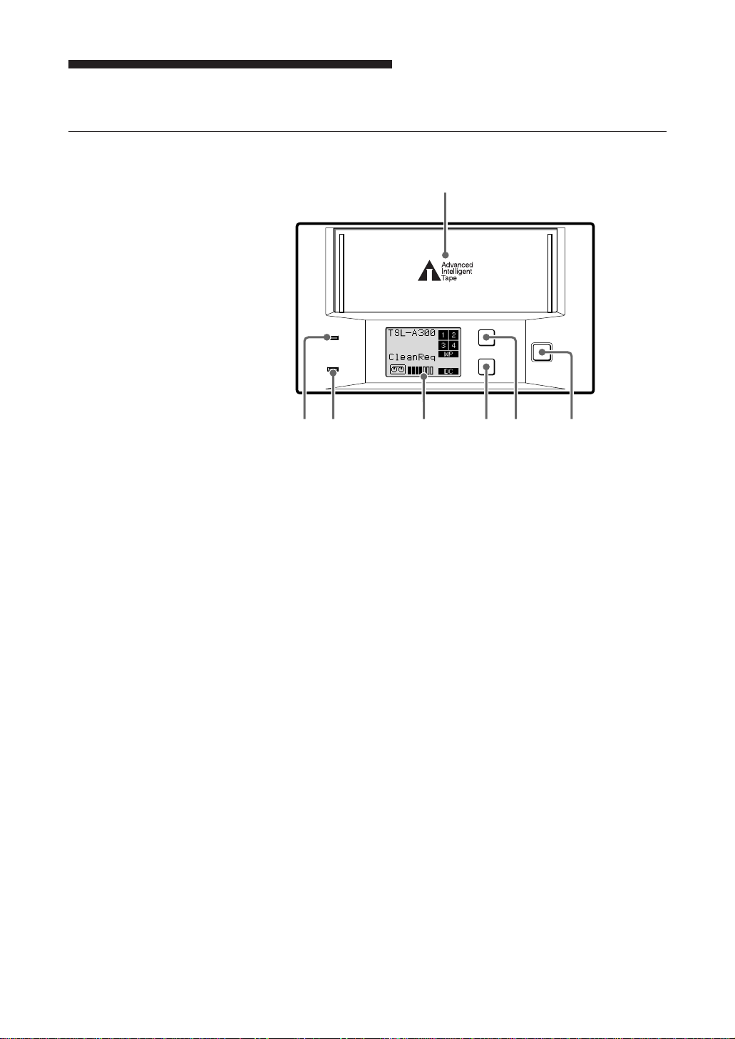
Part Names and Functions
BUSY
EJECT
SELECT
ENTER
TAPE
1
46
37 2
5
Front Panel
1 Magazine receptacle
Insert a magazine here.
Front panel
2 EJECT Button
Press this button to remove a magazine from the machine. It is also used
for menu operations on the display.
3 SELECT Button
Press this button to select a cartridge to be loaded. It is also used for
menu operations on the display.
4 ENTER Button
Press this button to load the cartridge selected by the SELECT button
into the AIT drive. It is also used for menu operations on the display.
Chapter 1 Introduction 7
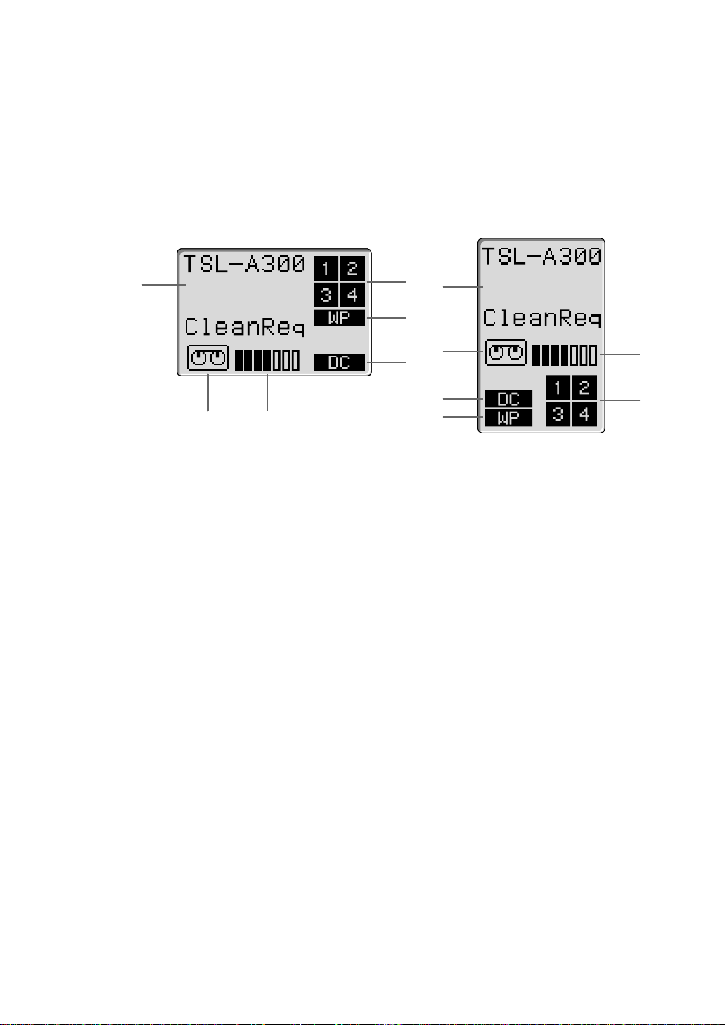
5 Liquid Crystal Display (LCD)
Displays the machine’s status.
The orientation of the display can be changed to match the direction of
viewing as described on page 13.
Horizontal Display Vertical Display
a
f
b
a
c
f
d
d
e
a Message Area
Indicates the machine’s operating status.
Warning or error messages may be displayed here depending on the
operating state.
The language of the messages may be selected from English, French,
German and Spanish as described on page 14.
b Cartridge Number Indicator
Displays the status of the cartridge in the magazine. The cartridge
number blinks while exchanging the cartridge. When a cartridge is
loaded from a magazine to the AIT drive, the cartridge number
disappears. When the cartridge is returned to the magazine, the number
blinks again.
c
Liquid Crystal Display
e
b
8 Chapter 1 Introduction
c Write-Protect Indicator
This indicator appears when the magazine or data cartridge is writeprotected by the write-protect tab.
d Data Compression Indicator
This indicator lights when data compression is enabled for the drive.
e Tape Position Indicator
Indicates the winding position of the tape in the cartridge loaded in the
AIT drive.
ppppppp Positioned near the beginning of the tape.
ppppπππ Positioned near the middle of the tape.
πππππππ Positioned near the end of the tape.
Tape winding position indicated by the Tape Position Indicator

f Cartridge Indicator
This indicator appears when a cartridge is loaded in the internal AIT
drive, and indicates the tape’s load status: when the tape is being loaded
or unloaded from the drive, this indicator blinks.
6 TAPE Indicator
Lights green when a data cartridge is loaded into the AIT-drive. The
indicator flashes while a cartridge is being loaded or unloaded.
7 BUSY Indicator
Lights green when the SCSI interface is ready for data transfer. This
indicator flashes while data is being read from or written to the cartridge
loaded into the AIT drive, while searching for data, or while the tape is
being rewound.
Chapter 1 Introduction 9
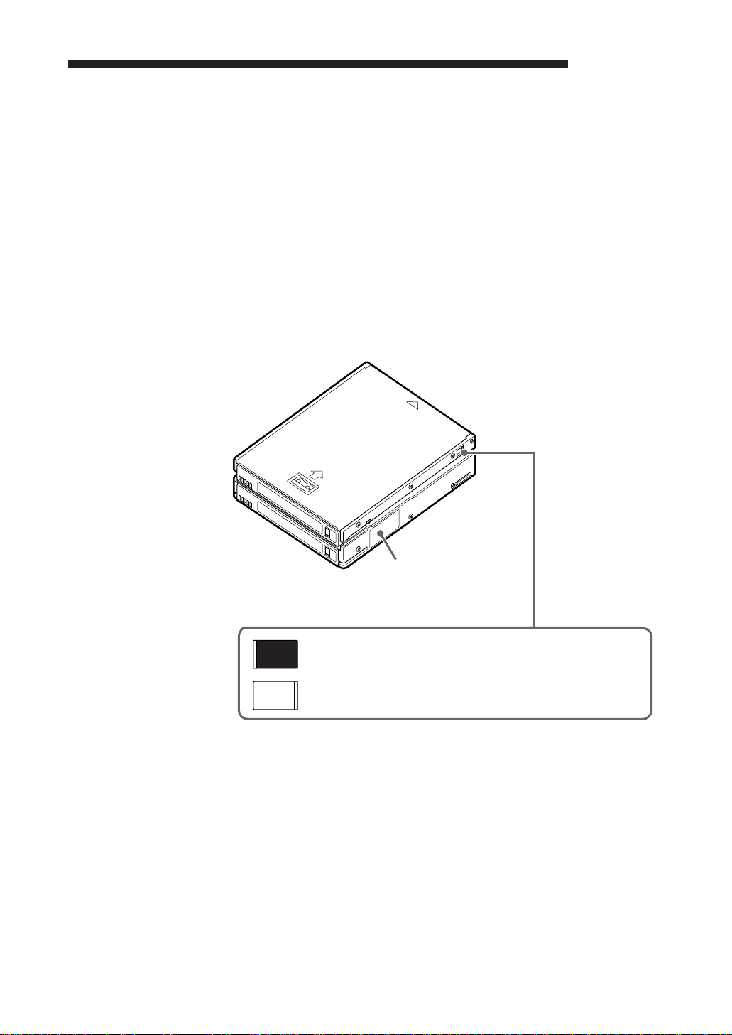
Magazine
1
1 Button
Press the button to remove cartridges from the magazine. Refer to page
15 to load cartridges, and to page 17 to remove cartridges.
2 Write protect tab
Used to inhibit writes to data cartridges. Sliding this tab to the left writeprotects all data cartridges, whether or not write protection is set on the
individual data cartridges.
2
Magazine
10 Chapter 1 Introduction

Chapter 2 Operation
This section describes users of the LCD (display), and procedures for loading
cartridges in the magazine, using the drive unit, and handing magazines and
cartridges.
Menu Settings and Checks
Certain machine settings can be made and viewed from the LCD Menu
screen, including model and firmware version display and the current SCSI
ID setting of the machine.
The Menu screen is controlled by the following procedure.
Note:
The magazine should be removed before switching display to the Menu
screen. When the magazine is inserted into the autoloader, the Menu screen
can only be displayed when the LCD shows “Ready”. To change the
language setting, the magazine must be removed.
1 Press and hold the SELECT button for 5 seconds.
The display changes to the Menu screen.
z Version
Auto Load
Unload
Contrast
Orientation
Language
Menu Screen
2 Press the SELECT button to move the cursor (z) among the menu items.
3 Press ENTER to display the setting screen for the selected item.
4 Choose the desired setting for the selected item as described in the
following descriptions of the choices for each setting screen.
If no further action takes place for 10 seconds, the menu is exited and
display returns to normal.
Chapter 2 Operation 11

Version Display
When Version is selected in the Menu screen, the following screen appears,
where you can confirm the autoloader model, SCSI ID and firmware version.
Auto Load Selection
TSL-A300C
SCSI ID#5
Ver. 0000
S/NL XXXXXXXX
S/ND XXXXXXXX
Version Screen
Model Name of this Machine
SCSI ID Number
Firmware Version
Auto Loader Serial Number
AIT Drive Serial Number
1 Note the displayed information.
2 Press the EJECT button.
The display returns to the Menu screen.
When Auto Load is selected in the Menu screen, the following screen
appears. From this screen you can select whether the first cartridge
automatically loads when a magazine is placed in the auto loader.
OFF: The cartridges are checked and auto loading does not occur. (This is
the factory default setting.)
Please use this as the usual mode of operation.
ON: The first cartridge automatically loads into the AIT drive after the
cartridges in the magazine have been checked.
12 Chapter 2 Operation
Auto Load
z OFF
ON
1 Press the SELECT button, if necessary, to move the cursor (z) to the
desired setting. You can press the EJECT button to cancel any change to
the selection and return to the Menu screen.
2 Press the ENTER button to accept the selection and return to the Menu
screen.

Unload Selection
When Unload is selected in the Menu screen, the following screen appears.
From this screen you can select what happens when the Unload (LUN0)
command is selected while the fourth cartridge is loaded into the AIT drive.
OFF: The cartridge is returned to the magazine and the first cartridge does
not automatically reload. (This is the factory default setting.)
Please use this as the usual mode of operation.
ON: The cartridge is returned to the magazine and the first cartridge is
automatically reloaded into the drive.
Unload
Continuous
z OFF
ON
1 Press the SELECT button, if necessary, to move the cursor (z) to the
desired setting. You can press the EJECT button to cancel any change to
the selection and return to the Menu screen.
2 Press the ENTER button to accept the selection and return to the Menu
screen.
Contrast Adjustment
Orientation Setting
When Contrast is selected in the Menu screen, the following screen appears.
You can adjust the display contrast from this screen.
Contrast
Adjustment
pppππππ
Contrast Adjustment Screen
1 Press the SELECT button, as necessary, to adjust the contrast.
2 Press the ENTER button.
The contrast setting is accepted and the display returns to the Menu
screen.
When Orientation is selected in the Menu screen, the following screen
appears, where you can select the orientation of the display to match your
viewing angle.
Chapter 2 Operation 13

Language Selection
Orientation
z Horizontal
R-side down
L-side down
Orientation Screen
1 Press the SELECT button, as necessary, to move the cursor (z) to the
desired setting.
The orientation of the displayed characters corresponds with the current
selection.
You can press the EJECT button to cancel any change to the selection
and return to the Menu screen.
2 Press the Enter button.
Accepts the selected display orientation and returns to the Menu screen.
The display orientation switches when exiting the Menu screen.
Note:
When making settings with the Menu screen, the display is always
oriented so that the top of the display corresponds with the top of the
unit.
Note:
To change the language setting, remove the magazine from the unit. The
language setting cannot be changed while the magazine is inserted.
When Language is selected in the Menu screen, the following screen appears,
where you can select the language of the displayed messages.
Language
z English
French
German
Spanish
Language Screen
1 Press the SELECT button, as necessary, to move the cursor (z) to the
desired setting.
You can press the EJECT button to cancel any change to the selection
and return to the Menu screen.
2 Press the ENTER button to accept the selection and return to the Menu
screen.
Note:
The Menu screen itself is always displayed in English.
14 Chapter 2 Operation
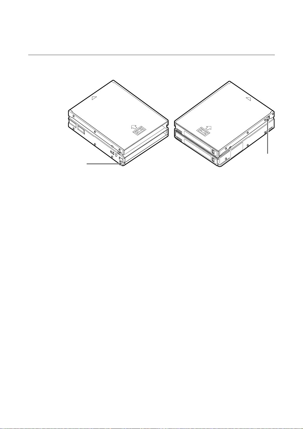
Loading Cartridges
Four data cartridges should be loaded in the magazine.
Cautions:
• Always load four cartridges into the magazine. Make sure that cartridges
are correctly oriented. Damage may result if fewer than four cartridges are
loaded or if the cartridges are loaded incorrectly.
• Incorrect cartridge orientation prevent insertion of the magazine into the
Autoloader. Check to ensure correct cartridge orientation.
Good Bad
Cartridge Orientation
Magazine Cartridge Number
Chapter 2 Operation 15
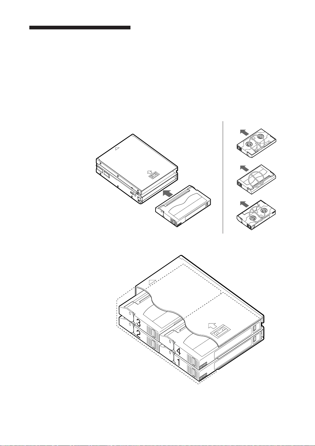
Load data cartridges into the magazine as follows.
1 First, load two data cartridges into the bottom shelf of the magazine as
shown in the figure below.
Load cartridge number 2 first, followed by cartridges 1.
Loading data cartridges into the bottom magazine shelf
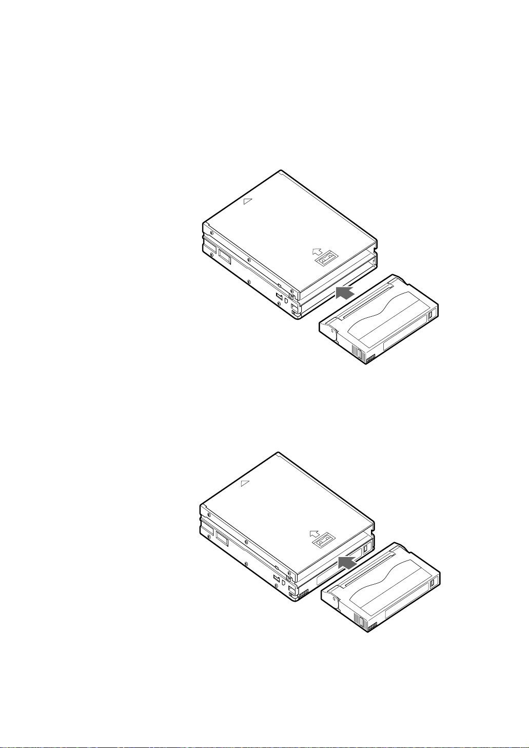
2 Load two data cartridges into the top shelf of the magazine as shown in
the figure below.
Load cartridge number 3 first, followed by cartridges 4.
Loading data cartridges into the top magazine shelf
16 Chapter 2 Operation
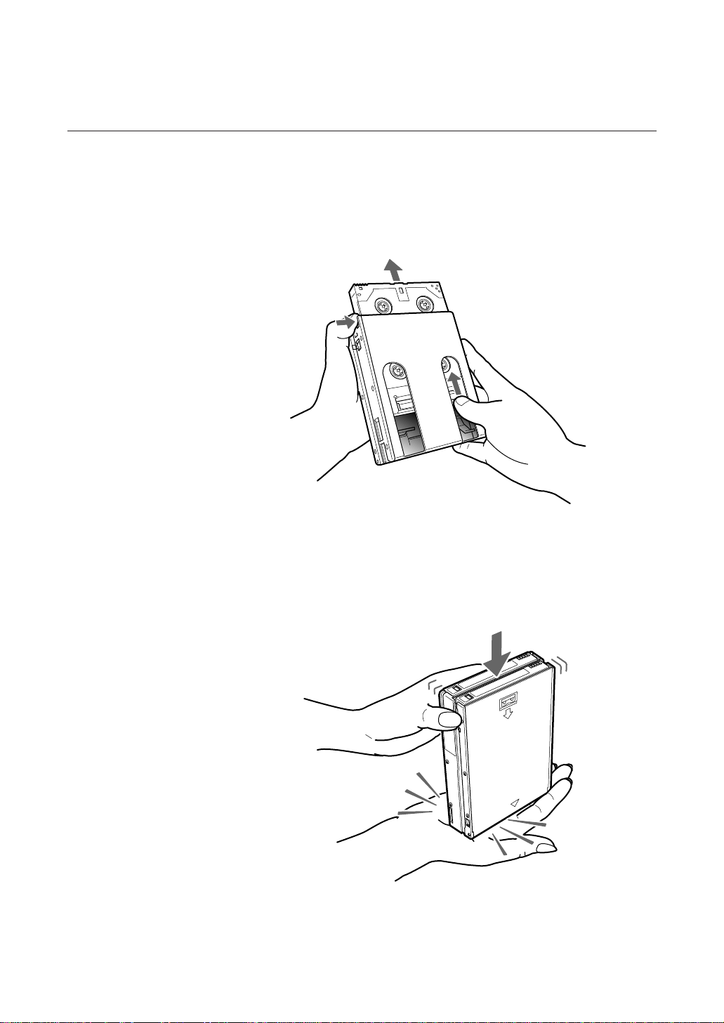
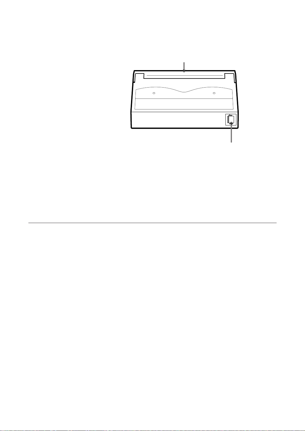
Removing Cartridges from the Magazine
Remove cartridges from the magazine as follows.
1 Pressing down on the magazine stopper, place your finger in the hole at
the rear of the magazine and push data cartridges toward the front of the
magazine.
Pushing cartridges from the rear of the magazine
2 Repeat step 1 to remove three cartridges.
3 Turn the magazine so that the open end faces up and tap it gently against
your hand or a soft object. This makes cartridges move from the top shelf
to the bottom shelf.
Moving top shelf cartridges to the bottom shelf
4 Using the same technique as step 1, slide the cartridge out from the
bottom position.
Chapter 2 Operation 17
How to Use the AIT Auto Loader Unit
EJECT
SELECT
ENTER
BUSY
TAPE
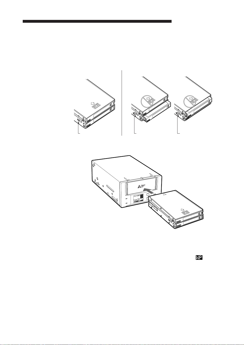
1 Be sure to push the cartridges all the way into the magazine. If the
cartridges are not pushed in all the way, the hook on the magazine
protrudes outward, and will prevent magazine insertion into the
Autoloader.
Good Bad
Hook not protruding Hook protruding Hook protruding
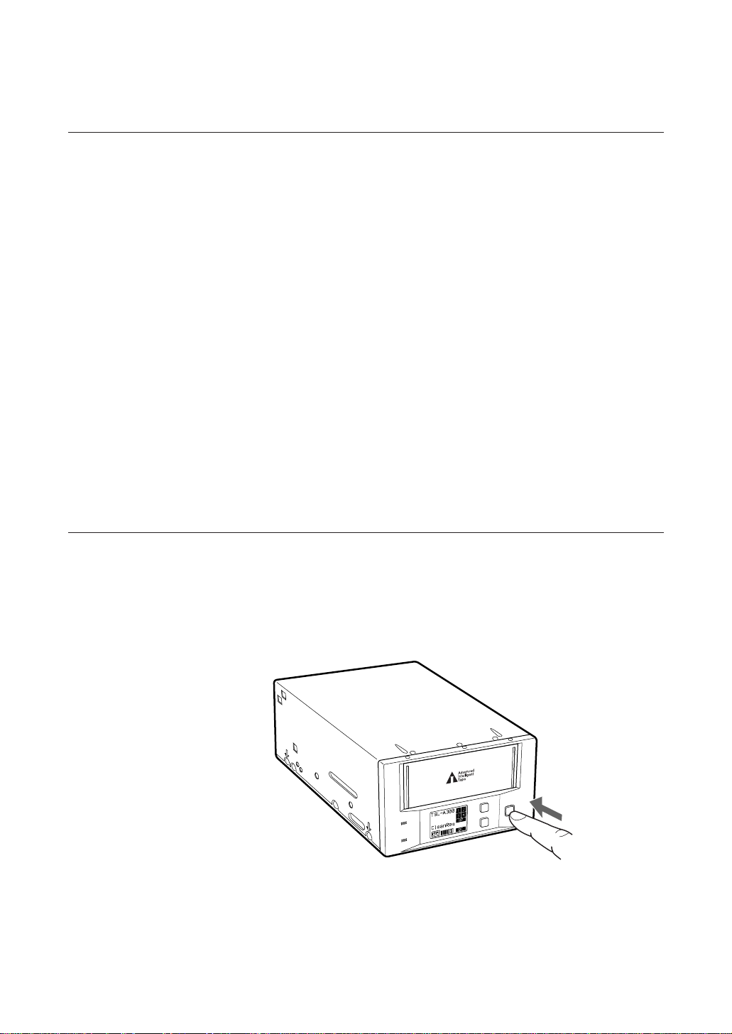
2 Ensure that the BUSY and TAPE indicators off, insert the magazine.
18 Chapter 2 Operation
Inserting the magazine
When the magazine is loaded, the following actions occur:
• After “Magazine Loading” appears, checking of the magazine starts.
• If the magazine is write-protected, the write-protect indicator ( ) appears.
• All cartridges are checked in order.
• As each cartridge is checked, its number blinks.
3 “Scan4 Ok” should be displayed, when all cartridge numbers display on
the LCD, a cartridge to be loaded into the AIT drive may be selected by
computer software or by the SELECT or ENTER buttons on the
machine. When a cartridge is loaded into the AIT drive, the TAPE
indicator lights.
4 Data may be read or written on the tape using computer software. While
reading or writing, the BUSY indicator lights.
Data Cartridge Selection
You can select data cartridges loaded into the magazine as necessary by using
the software on your computer.
Data cartridges can be selected with the SELECT and ENTER buttons on this
machine, by the following procedure.
1 Press the SELECT button to display a cartridge number on the LCD, and
press it repeatedly to change the selected data cartridge number.
2 When the desired cartridge number is selected, press the ENTER button.
The cartridge currently in the AIT drive is unloaded, and the cartridge
selected above is loaded into the drive.
Cautions:
• After inserting the magazine, about 75 seconds are needed for checking
the cartridges in the magazine. During that time, the SELECT button is
disabled. The SELECT button is also disabled when “Ready” is not
displayed.
• The SELECT and ENTER buttons have no effect if pressed while the
BUSY indicator is flashing.
Ejecting the Magazine
Press the EJECT button.
“Ejecting Magazine” appears, and after the cartridge unloads from the AIT
drive to the magazine, the magazine automatically ejects.
As much as two minutes may be required to eject a magazine.
SELECT
EJECT
BUSY
TAPE
Ejecting the magazine
ENTER
Caution:
The EJECT button has no effect if pressed while the BUSY indicator is
flashing.
Chapter 2 Operation 19
Taking Care of Magazines and Cartridges
Use Precautions
• Avoid heavy vibration and dropping.
• The shutter on the face of the cartridge is opened automatically when it is
inserted into the drive. Do not open the shutter by hand, as touching the tape
may damage it.
• Magazines and cartridges are carefully adjusted during assembly at the
factory. Please do not try to open them or take them apart.
• The write-protect tabs on magazines and cartridges prevent the tape from
being written to or accidentally erased. If you do not need to write to the
tape, move the magazine or cartridge write-protect tab to the write-protect
position.
Label attachment
position
SAVE
REC
Slide the tab toward SAVE to prevent data from being written
Slide the tab toward REC to allow data to be written
Magazine write-protect tab and label attachment position.
20 Chapter 2 Operation
• In case of a sudden change in temperature, condensation may interfere with
• Avoid unnecessarily loading/unloading cartridges to/from the AIT drive if
Storage Precautions
Lid
Push the switch to the left to enable writing and erasure. ?
Push the switch to the right to protect the tape from writing or
accidental erasure. /
Cartridge write-protect tab
reading and writing to a tape.
you do not need to write or read a tape.
• Keep the magazine in its case when not in use.
• Avoid storing cartridges in dusty places, in direct sunlight, near heaters or
air conditioners, or in humid locations.
• Do not place cartridges on the dashboard or in a storage tray in a car.
Chapter 2 Operation 21

Head Cleaning
To maintain the reliability of the AIT autoloader unit, clean the head
periodically using a cleaning tape (sold separately).
“CleanReq” is displayed when the head needs to be cleaned.
How to Clean
1 Load three data cartridges and one cleaning cartridge into the magazine.
2 Insert the magazine into the autoloader.
3 Press the SELECT button to select the cartridge number of the cleaning
4 Press the ENTER button.
cartridge.
The cleaning cartridge loads into the AIT drive.
The cleaning cartridge cleans the head automatically and returns to the
magazine.
22 Chapter 2 Operation
Installation
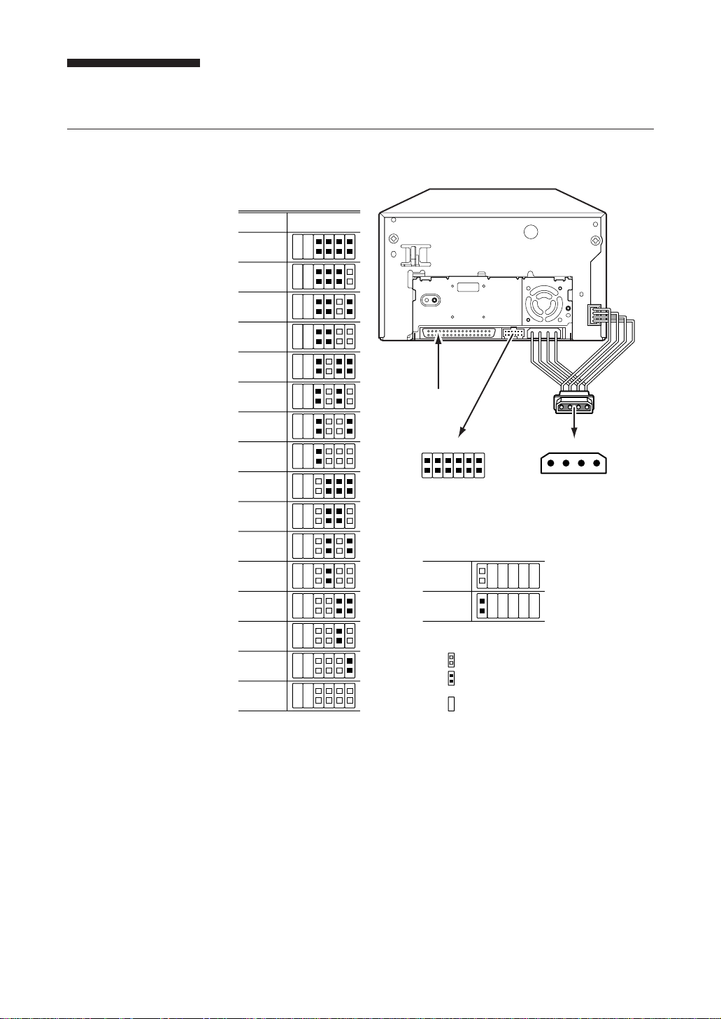
SCSI Connection/Setting the SCSI ID
SCSI ID
SCSI ID
0
1
2
3
4
321
P.D.
N.C.
0
Parity Disable Jumper
5
6
7
8
9
10
11
12
13
14
15
SCSI Connector
Jumpers
Parity Disable
No Connection
Parity
Disable
Enable
Note: = CLOSED / Jumper
Power Connector
5V GND GND 12V
SCSI ID 3
SCSI ID 2
SCSI ID 1
SCSI ID 0
= OPEN / Jumper not installed
Don't care
4 3 2 1
Parity check function can be disabled by Jumper. Parity check is disabled
while left end jumper is installed. Parity generate function is always enabled.
Chapter 2 Operation 23
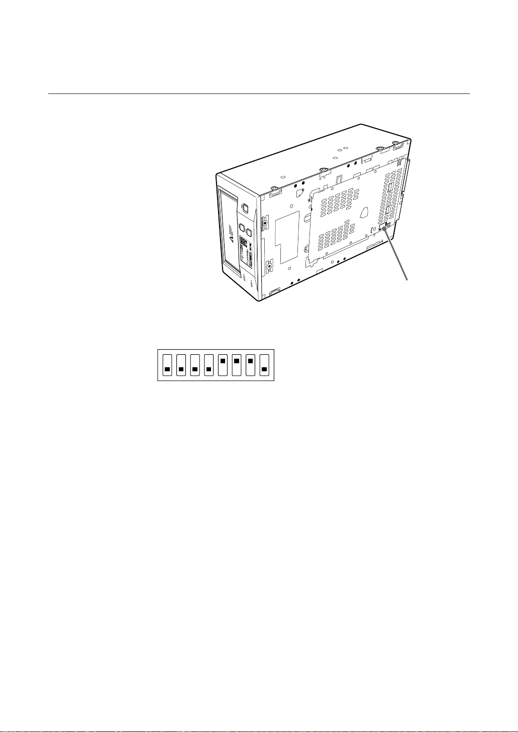
Option Switches (DIP Switch)
DIP Switch Positions
DIP Switch
ON
12345678
Note:
The TSL-A310C is not equipped with internal termination. When using this
unit, connect a differential SCSI bus terminator or a device with internal
termination to the end of the SCSI bus.
The TSL-A300C is equipped with internal termination.
Data Compression Control DIP switch
Data compression can be selected by DIP switches. Data compression is
enabled while position 7 [DC Control (1)] is ON. Control by host can be
disabled when position 8 [DC Control (2)] is ON.
1 Reserved (OFF)
2 Reserved (OFF)
3 Reserved (OFF)
4 Reserved (OFF)
5 Terminator Power (ON)
6 Terminator Enable (No connection for TSL-A310C)
7 DC Control (1) (ON)
8 DC Control (2) (OFF)
24 Chapter 2 Operation

Interface Implementation
Supported SCSI Messages
Abort
Bus Device Reset
Command Complete
Disconnect
Extended Message
-Synchronous Data Transfer Request
Extended Message
-Wide Data Transfer Request
Identify (w/&w/o Disconnect)
Initiator Detected Error
Message Parity Error
Message Reject
No Operation
Restore Pointers
Save Data Pointer
Supported SCSI Commands
Erase
Initialize Element Status (LUN=1)
Inquiry (LUN= 0 or 1)
Load/Unload (LUN= 0 or 1)
Locate
Log Select
Log Sense
Mode Select (6)
Mode Sense (6) (LUN= 0 or 1)
Move Medium (LUN= 0 or 1)
Prevent Allow Medium Removal (LUN= 0 or 1)
Read
Read Block Limits
Read Buffer
Read Element Status (LUN= 0 or 1)
Read Position
Receive Diagnostic Results
Release Unit
Request Block Address
Request Sense
Reserve Unit
Rewind
Seek Block
Send Diagnostic (LUN= 0 or 1)
Space
Test Unit Ready (LUN= 0 or 1)
Verify
Write
Write Buffer
Write Filemarks
Chapter 2 Operation 25
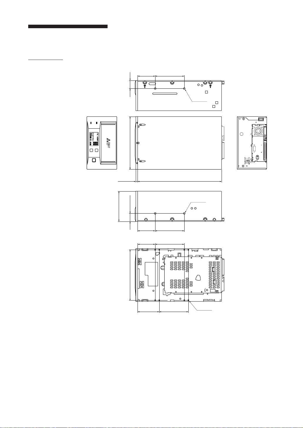
Mounting Holes
TSL-A300C
1.87
[47.5mm]
0.86
[21.8mm]
BUSY
TAPE
3.25
[82.5mm]
5.75
0.20
[5.0mm]
0.86
[146.0mm]
[21.8mm]
[47.5mm]
[47.5mm]
1.87
1.87
SELECT
ENTER
EJECT
3.12
[79.25mm]
[228.6mm]
3.12
[79.25mm]
3.12
[79.25mm]
2–M3
9.00
2–M3
26 Chapter 2 Operation
5.50
[139.7mm]
2.30
[58.5mm]
3.12
[79.25mm]
8–M3
Note:
Maximum mounting screw thread length is 3.0 mm. Longer thread length
may damage the drive.
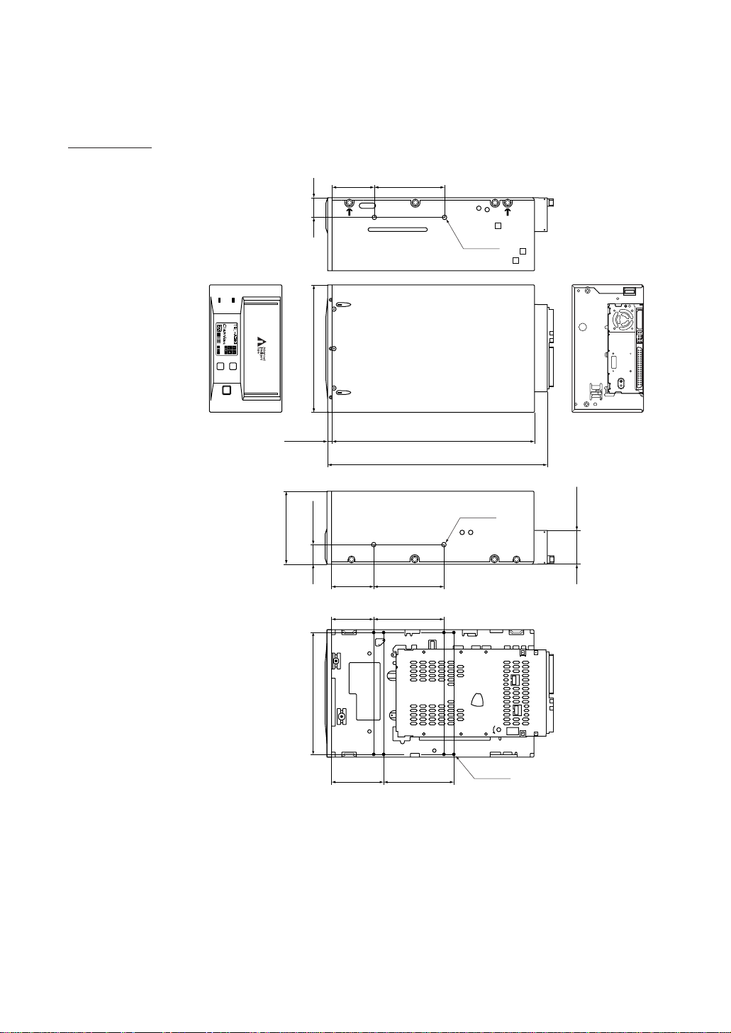
TSL-A310C
1.87
[47.5mm]
0.86
[21.8mm]
BUSY
TAPE
3.25
[82.5mm]
5.75
0.20
[5.0mm]
0.86
[146.0mm]
[21.8mm]
[47.5mm]
[47.5mm]
1.87
1.87
SELECT
ENTER
EJECT
3.12
[79.25mm]
[228.6mm]
3.12
[79.25mm]
3.12
[79.25mm]
9.00
9.55
[242.6mm]
2–M3
2–M3
1.62
[41.2mm]
5.50
[139.7mm]
2.30
[58.5mm]
3.12
[79.25mm]
8–M3
Note:
Maximum mounting screw thread length is 3.0 mm. Longer thread length
may damage the drive.
Chapter 2 Operation 27
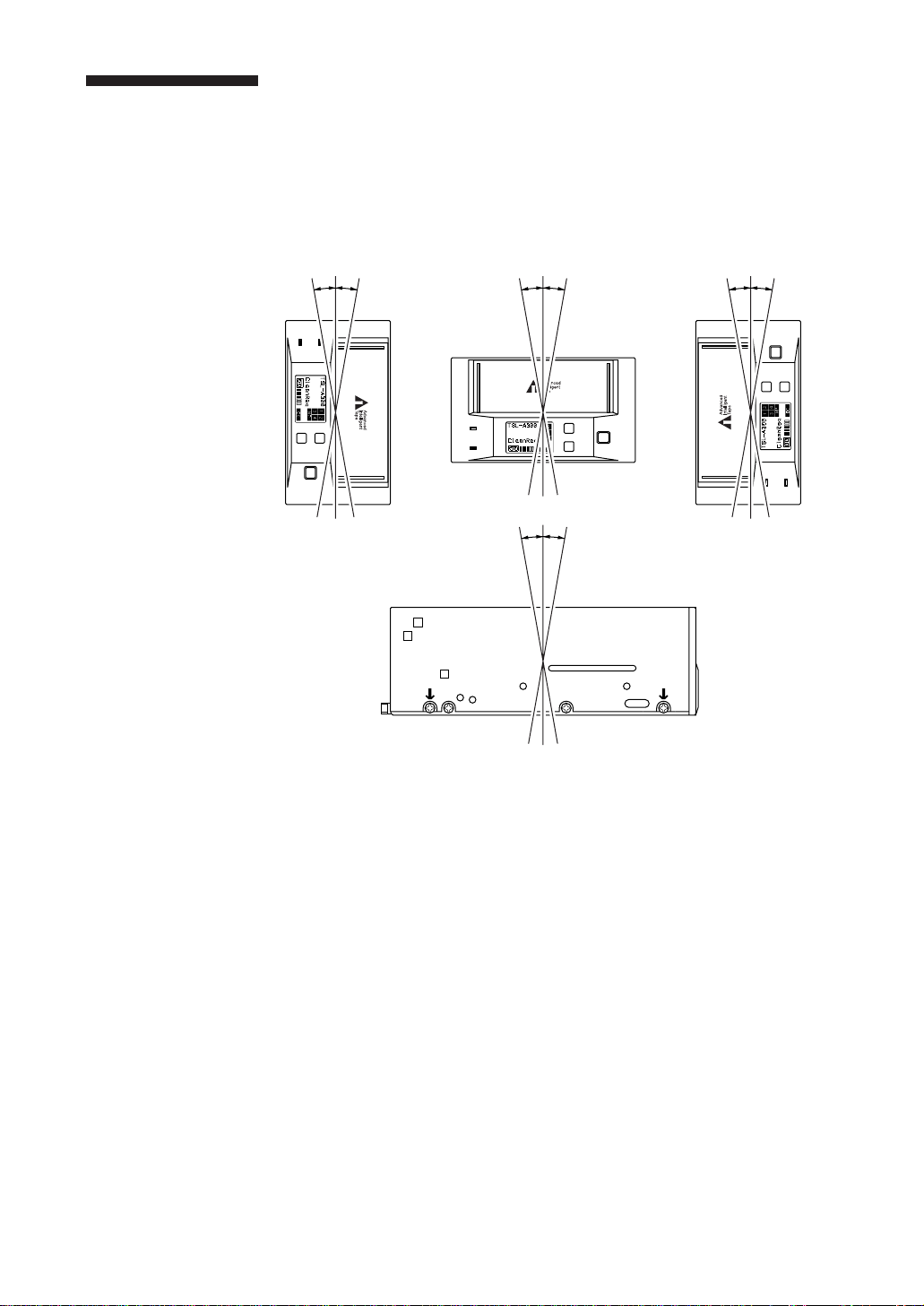
Orientation
The TSL-A300C can be installed in three different mounting positions as
shown in the figure below.
Each position has a maximum tolerance of +/– 10 degrees.
10 °
10 °
BUSY
TAPE
SELECT
ENTER
EJECT
BUSY
TAPE
10 °
10 °
10 °
10 °
SELECT
EJECT
ENTER
10 °
10 °
EJECT
ENTER
SELECT
BUSY
TAPE
28 Chapter 2 Operation

Appendix
Specifications
Performance
Storage Capacity
Approx 100-200 Gbytes
(When using compression with 4
AIT-1 cartridges)
Bit Error Rate
less than 10
Data Transfer Rate (Tape)
3 MB/s uncompressed
6 MB/s compressed
Burst Data Transfer Rate (SCSI)
10 MB/s maximum, asynchronous
20 MB/s maximum, synchronous
Magazine insertion/ejection time
2.5 seconds(typical)
Cartridge exchange time(control by SCSI)
55 seconds(typical, when using
MIC cartridges)
Rewind time less than 80 seconds (with 170 m
tape)
-17
Operating Environment
Operating
Temperature: 5 to 40 °C
Humidity: 20 to 80%
(no condensation)
(Max wet bulb temperature: 26°C)
Non-Operating
Temperature: –40 to +70 °C
Humidity: 10 to 90%
Shock
Operating
No Data Loss
Half Sine
5 G Peak 3 ms
3 axes, 3 directions
*Interval 10 seconds
Non-Operating
No Device Damage
Half Sine
90 G Peak 3 ms
(30 G Peak 11 ms)
3 axes, 3 directions
*Interval 10 seconds
Vibration
Operating
Swept Sine 5 to 500 Hz
*0.25 G Peak 1 Octave/min.
3 axes,3 directions
Non-Operating
Swept Sine 5 to 500 HZ
*0.5 G Peak 1 Octave/min.
3 axes,3 directions
Altitude
Operating
0 to 3048 m
Acoustic Noise
Streaming Write/Read : 35 dBA
Magazine Insert/Eject : 65 dBA
Cartridge Change : 70 dBA
Door Open/Close : 80 dBA
Note: The sound meter, set to the A scale, is
located 1m in front of the center of the
drive front panel.
Appendix 29

Power Requirements &
Miscellaneous
Power 5 VDC Tolerance: ±5 %
Current:1.8 A(typ.)
:3.0 A(max.)
Ripple :100 mVP-P
12 VDC Tolerance: ±10 %
Current:0.35 A(typ.)
:1.5 A(max.)
Ripple :150 mVP-P
AIT Autoloader Dimensions
(TSL-A300C) 146.0 × 82.5 × 228.6 mm
(W × H × D)
(excluding protruding parts)
(TSL-A310C) 146.0 × 82.5 × 242.6 mm
(W × H × D)
(excluding protruding parts)
Magazine Dimensions
104.0 × 36.5 × 131.5 mm
(W × H × D)
Weight
Autoloader 2.5 kg
(not including magazine)
Magazine 250 g
(not including cartridges)
Specifications may be subject to change, in the
interest of technological improvement, without
notice or obligation.
Third Party Support Contacts
Host Adapter Vendors Phone Numbers
Adaptec 408-945-8600
ATTO 716-691-1999
Bus Logic 408-492-9090
DPT 407-830-5522
Future Domain 714-253-0400
Initio 408-988-1919
Qlogic 714-438-2200
Ultera Systems Inc. 714-367-8800
30 Appendix
 Loading...