

Sony TRINITRON KV-J21MF1AK, TRINITRON KV-J21MF3, TRINITRON KV-J21MN1AK, TRINITRON KV-J21PF1 Service Manual
MODEL COMMANDER DEST. CHASSIS NO.
KV-J21MF1AK
RM-883 India SCC-K67K-A
KV-J21MF3
RM-883 India SCC-K76F-A
KV-J21MN1AK
RM-883 India SCC-K67L-A
KV-J21PF1
RM-883 India SCC-K67G-A
SERVICE MANUAL
MODEL COMMANDER DEST. CHASSIS NO.
CHASSIS
TRINITRON
®
COLOR TV
BG-1S (D)

– 2 –
KV-J21MF1AK/J21MF3
KV-J21MN1AK/J21PF1
RM-883
SPECIFICATIONS
CAUTION
SHORT CIRCUIT THE ANODE OF THE PICTURE TUBE AND
THE ANODE CAP T O THE METAL CHASSIS, CRT SHIELD, OR
CARBON PAINTED ON THE CRT, AFTER REMOVING THE
ANODE.
SAFETY-RELATED COMPONENT WARNING!!
COMPONENTS IDENTIFIED BY SHADING AND MARK ! ON
THE SCHEMATIC DIAGRAMS, EXPLODED VIEWS AND IN THE
PARTS LIST ARE CRITICAL T O SAFE OPERATION. REPLACE
THESE COMPONENTS WITH SONY PARTS WHOSE PART
NUMBERS APPEAR AS SHOWN IN THIS MANUAL OR IN SUPPLEMENTS PUBLISHED BY SONY.
Note
Power requirements 110-240 V AC, 50/60 Hz
Power consumption (W) Indicated on the rear of the TV
Television system B/G, I, D/K, M Except for KV-J21PF1
B/G KV-J21PF1
Color system PAL, PAL 60, SECAM, NTSC4.43, NTSC3.58 Except for KV-J21PF1
PAL, PAL 60,NTSC4.43, NTSC3.58 (AV IN) KV-J21PF1
Stereo system NICAM Stereo B/G, I; A2 Stereo (German) B/G KV-J21MN1AK only
Channel coverage
B/G VHF: E2 to E12/UHF: E21 to E69/CATV: S01 to S03, S1 to S41
I UHF: B21 to B68/CATV: S01 to S03, S1 to S41 Except for KV-J21PF1
D/K VHF: C1 to C12, R1 to R12/UHF: C13 to C57, R21 to R60/
CATV: S01 to S03, S1 to S41, Z1 to Z39 Except for KV-J21PF1
M VHF: A2 to A13/UHF: A14 to A79/
CATV: A-8 to A-2, A to W+ 4, W+ 6 to W+ 84 Except for KV-J21PF1
Audio output (speaker) 3W + 3W KV-J21MF3/J21PF1
3W + 3W + 7W (3D WOOFER) KV-J21MF1AK/J21MN1AK
Inputs Antenna: 75 ohms
VIDEO IN jacks: phono jacks
Video: 1 Vp-p, 75 ohms
Audio: 500 mVrms, high impedance
Outputs Headphone jack: minijack
MONITOR OUT jacks: phono jacks
Video: 1 Vp-p, 75 ohms
Audio: 500 mVrms
Picture tube 21 in.
Tube size (cm) 54 Measured diagonally
Screen size (cm) 51 Measured diagonally
Dimensions (w/h/d, mm) 610 × 470 × 488 KV-J21MF3/J21PF1
610 × 510 × 488 KV-J21MF1AK/J21MN1AK
Mass (kg) 23 KV-J21MF3/J21PF1
25 KV-J21MF1AK/J21MN1AK
Design and specifications are subject to change without notice.

– 3 –
KV-J21MF1AK/J21MF3
KV-J21MN1AK/J21PF1
RM-883
TABLE OF CONTENTS
1. GENERAL.................................................................... 4
2. DISASSEMBLY
2-1. Rear Cover Removal............................................ 11
2-2. A Board Removal ................................................ 11
2-3. Service Position ................................................... 11
2-4. Replacement of Parts ........................................... 12
2-5. Demagnetization Coil Removal .......................... 12
2-6. Picture Tube Removal.......................................... 13
3. SET-UP ADJUSTMENTS
3-1. Beam Landing ...................................................... 14
3-2. Convergence......................................................... 15
3-3. Focus Adjustment ................................................ 17
3-4. G2 (Screen) and White Balance Adjustments..... 17
4. SELF DIAGNOSIS FUNCTION............................ 18
5. CIRCUIT ADJUSTMENTS
5-1. Adjustments with Commander ............................ 19
5-2. Adjustment Method ............................................. 20
5-3. A Board Adjustment after IC003 (Memory)
Replacement......................................................... 25
5-4. Picture Distortion Adjustment ............................. 25
6. DIAGRAMS
6-1. Block Diagram ...................................................... 27
6-2. Circuit Boards Location ....................................... 31
6-3. Schematic Diagrams and Printed Wiring Boards. 31
(1) Schematic Diagrams of A3, C and K1 Boards..... 35
(2) Schematic Diagram of A Board............................ 43
(3) Schematic Diagrams of A11, A12, K and
VM Boards............................................................ 48
6-4. Semiconductors..................................................... 57
7. EXPLODED VIEW
7-1. Chassis .................................................................. 59
7-2. 3D Speaker (KV-J21MF1AK/J21MN1AK only) 61
8. ELECTRICAL PARTS LIST.................................... 62
Section Title Page Section Title Page
– 4 –
KV-J21MF1AK/J21MF3
KV-J21MN1AK/J21PF1
RM-883
SECTION 1
GENERAL
The operating instructions mentioned here are partial abstracts from the
Operating Instructions Manual. The page numbers of the Operating
Instruction Manual remain as in this manual.
2
3
p KV-J21MF1AK/J21MN1AK
B/G I D/K M
TV SYSTEM
AUTO PROGR
TV SYSTEM
AUTO PROGR
p KV-J21MF1AK/J21MN1AK/
J21MF3
2
1
– 5 –
KV-J21MF1AK/J21MF3
KV-J21MN1AK/J21PF1
RM-883
Getting Started
5
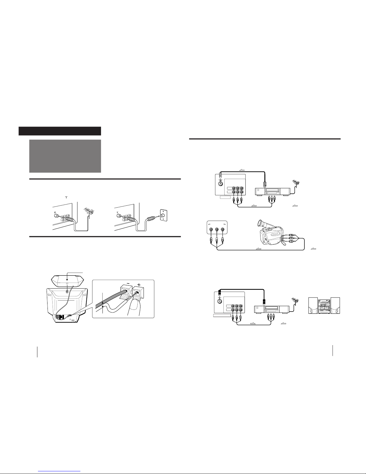
Connecting audio/video equipment using MONITOR OUT jacks
When using the video input jacks
Do not connect video equipment to the video input jacks at the front and the rear of your TV simultaneously; otherwise the picture will
not be displayed properly on the screen.
to antenna
output
or
MONITOR OUT
Rear of TV
When recording through the MONITOR OUT jacks
If you change the channel or video input while recording with a VCR, the channel or video input you are recording also will be changed.
to antenna socket
Audio system
Connecting optional equipment
You can connect optional audio/video equipment to your TV such as a VCR, multi disc player, camcorder, video
game or stereo system.
Connecting video equipment using video input jacks
VIDEO IN
Rear of TV
Front of TV
VIDEO
L
(
MONO
)
VIDEO INPUT
AUDIO
R
VIDEO
IN
MONITOR
OUT
VIDEO
L
(
MONO
)
AUDIO
R
to video
and audio
outputs
: Signal flow
: Signal flow
to video and
audio outputs
Camcorder
to antenna
output
VCR
to antenna socket
VIDEO
IN
MONITOR
OUT
VIDEO
L
(
MONO
)
AUDIO
R
: Signal flow
to video
and audio
inputs
VCR
Getting Started
4
Connections
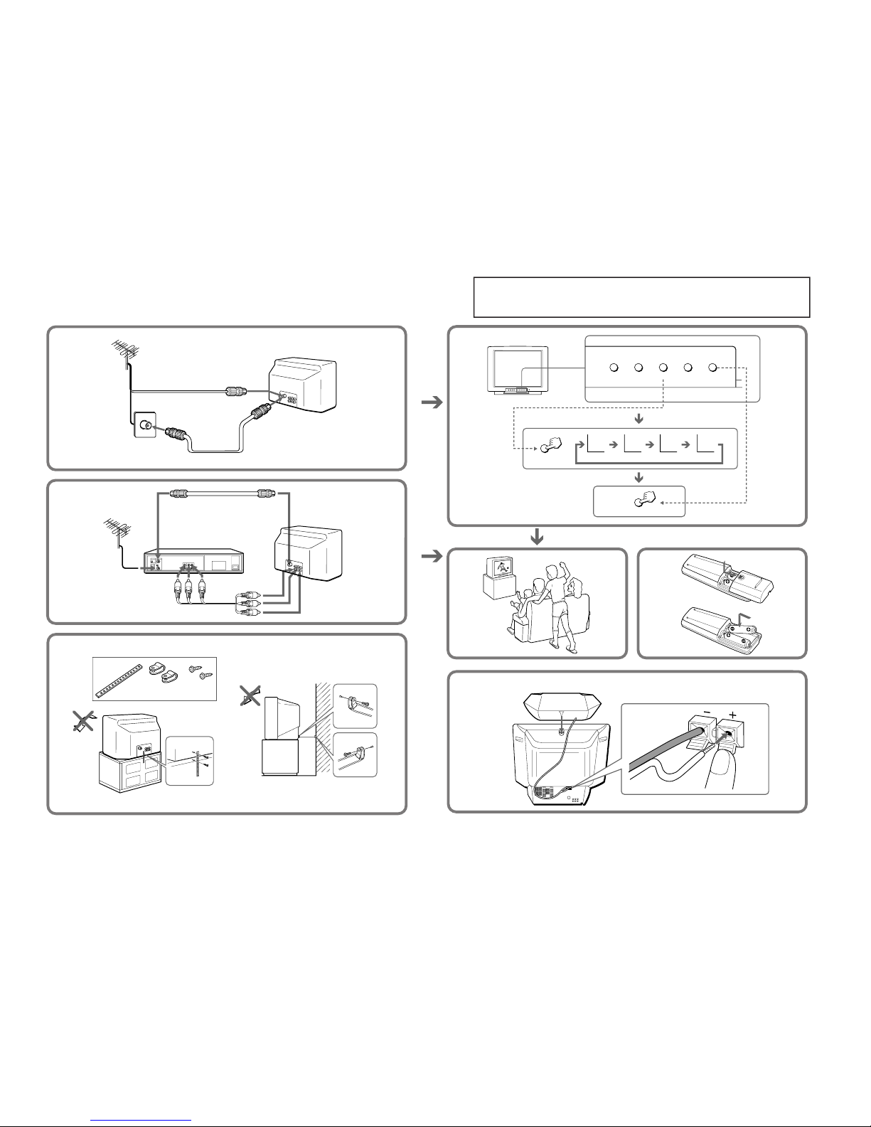
Connecting a VHF antenna or a combination VHF/UHF antenna
— 75-ohm coaxial cable (round)
Attach an optional IEC antenna connector to the 75-ohm coaxial cable.
Plug the connector into the
(antenna) socket at the rear of the TV.
Getting Started
Connecting the 3D WOOFER
p KV-J21MF1AK/J21MN1AK only
1
Attach the 3D WOOFER into the foothold on the top of the TV.
2
Connect the wires to the 3D WOOFER (8Ω) terminals at the rear of the TV.
The red wire should be connected to the ‘ red terminal and the black wire to the ’ black terminal.
Notes
• Connect only the supplied 3D WOOFER; otherwise the TV may malfunction.
• Unplug the TV from the wall outlet when connecting the 3D WOOFER.
• To prevent a malfunction caused by a short circuit of the terminals, make sure that none of the 3D WOOFER wire strands stick out,
making contact with the neighbouring speaker terminal.
1
2
3D WOOFER
Black wire
Red wire
On a wall
or
Rear of TV
Rear of TV
– 6 –
KV-J21MF1AK/J21MF3
KV-J21MN1AK/J21PF1
RM-883
Getting Started
6
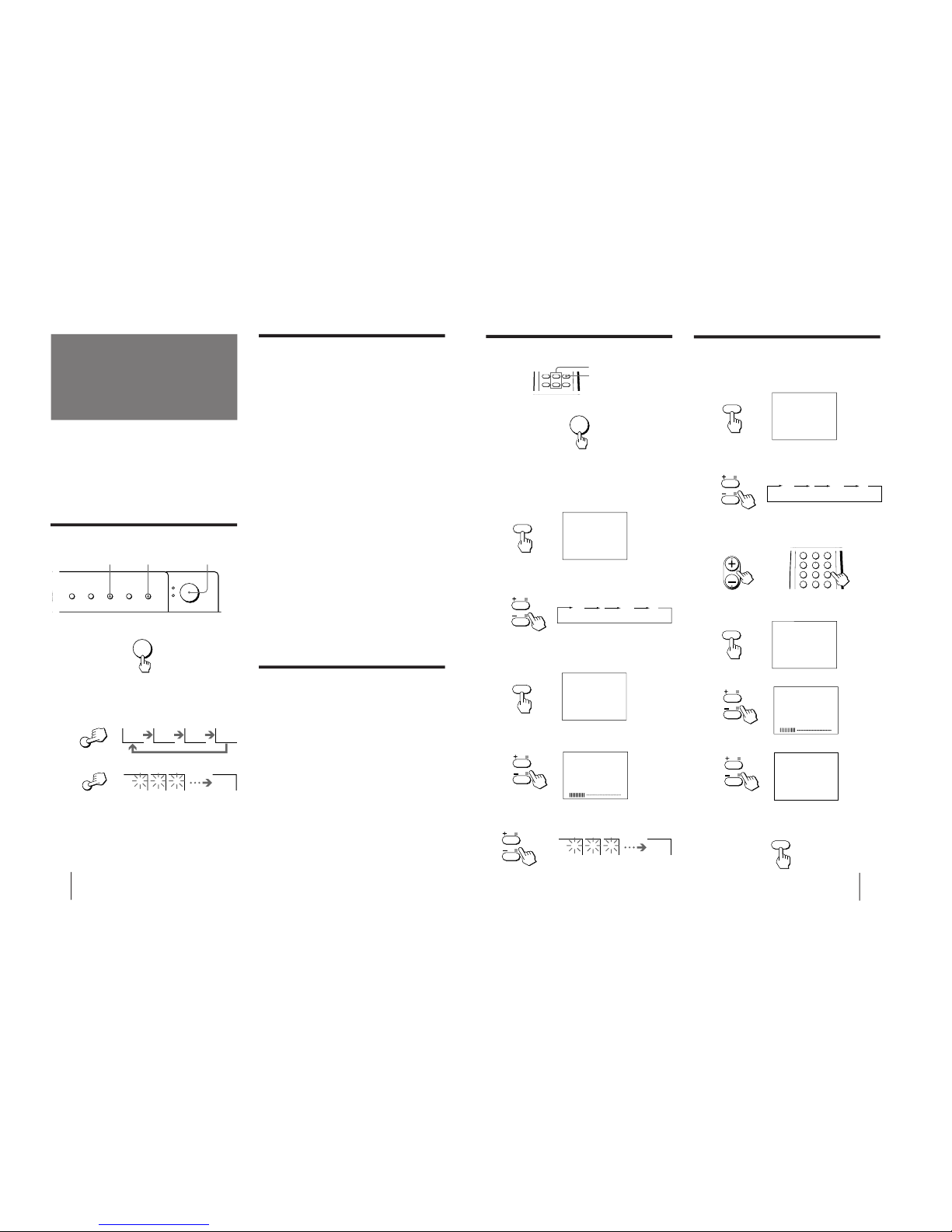
Presetting channels
Presetting channels manually using the
buttons on the TV
1
Press MANUAL PROGR.
2
Press PROGR +/– on the remote commander
until the required program position
appears on the screen.
3
Press TV SYSTEM until your local TV system
appears (KV-J21MF1AK/J21MN1AK/J21MF3
only).
4
Press VOLUME +/– until the required channel
picture appears on the screen.
5
Press MANUAL PROGR.
If the TV system is not properly selected
(KV-J21MF1AK/J21MN1AK/J21MF3 only)
The color of the picture may be poor and/or the sound
may be noisy. In this case, select the appropriate TV
system.
1 Press PROGR +/– on the remote commander to
select the program position.
2 Press TV SYSTEM until the picture and sound
become normal.
Notes (KV-J21MF1AK/J21MN1AK/J21MF3 only)
• If you do not know your local TV system, consult your nearest
authorized service center or dealer.
• The setting of the TV SYSTEM is memorized for each program
position.
Disabling program positions using the
buttons on the TV
By disabling unused or unwanted program positions,
you can skip those positions when you press
PROGR +/– on the remote commander.
1
Press PROGR +/– on the remote commander
until the unused or unwanted program
position appears on the screen.
2
Press MANUAL PROGR.
3
Press PIC MODE on the remote commander.
4
Press MANUAL PROGR.
To cancel the skip setting
Preset the channel manually or automatically again.
You can preset up to 100 TV channels in numerical
sequence from program position 1 automatically.
To change the channel for a particular program
position or to receive a channel with a weak signal,
you can preset the channel manually. You can also
disable program position.
You can preset TV channels using the buttons on the
TV or the remote commander.
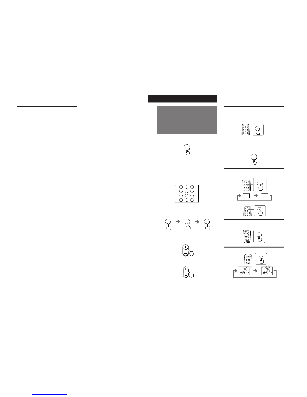
Presetting channels automatically
using the buttons on the TV
Front of TV
1
Press POWER to turn on the TV.
When the TV is turned on in standby mode, press
POWER on the remote commander.
2
Press TV SYSTEM until your local TV system
appears
(KV-J21MF1AK/J21MN1AK/J21MF3 only)
3
Press AUTO PROGR.
To start presetting channels automatically
from the specified program position
1 Press MANUAL PROGR.
2 Press TV SYSTEM to select your local TV system
(KV-J21MF1AK/J21MN1AK/J21MF3 only).
3 Press PROGR +/– to select the program position.
4 Press AUTO PROGR.
2
3
1
TV SYSTEM
B/G I D/K
M
MANUAL PROGR
COLOR SYSTEM
SELECT
TV SYSTEM
AUTO PROGR
POWER
AUTO PROGR
1 2 3
1
POWER
Getting Started
7
POWER
B/G I D/K M
Presetting channels automatically
using the remote commander
1
Press POWER to turn on the TV.
When the TV is turned on in standby mode, press
POWER on the remote commander.
2
Press SELECT until “TV SYSTEM” appears
(KV-J21MF1AK/J21MN1AK/J21MF3 only).
3
Press + or – to select your local TV system
(KV-J21MF1AK/J21MN1AK/J21MF3 only).
4
Press SELECT until “AUTO PROGRAM”
appears.
5
Press + or – .
6
Press + or – .
Presetting channels manually using the
remote commander
1
Press SELECT until “TV SYSTEM” appears
(KV-J21MF1AK/J21MN1AK/J21MF3 only).
2
Press + or – to select your local TV system
(KV-J21MF1AK/J21MN1AK/J21MF3 only).
3
Press PROGR +/– or a number button until
the required program appears on the
screen.
4
Press SELECT until “MANUAL PROGRAM”
appears.
5
Press + or – .
6
Press + or – .
The selected channel appears on the screen.
7
Press SELECT to return to normal screen.
SELECT
TV SYSTEM : B/G
SELECT
TV SYSTEM : B/G
B/G I D/K M
or
1
2
3
4
6
7
8
9
÷
0
5
PROGR
JUMP
SELECT
MANUAL PROGRAM
1 2 3
1
VHF LOW B/G
SELECT
AUTO PROGRAM
VHF LOW B/G
1
SELECT
+ or –
SELECT
– 7 –
KV-J21MF1AK/J21MF3
KV-J21MN1AK/J21PF1
RM-883
Getting Started
8
If you are not satisfied with the picture
and sound quality
You may be able to further improve the picture and
sound quality by using fine tuning as below:
1
Select the program position you want to
adjust.
2
Press SELECT until “MANUAL PROGRAM”
appears on the screen.
3
Press + or – on the remote commander
once.
4
Press DISP until “FINE” appears on the
screen.
5
Press + or – continuously until you are
satisfied with the picture and sound
quality.
6
Press SELECT to return to normal screen.
9
Operations
VIDEO
HOLD
1
2
3
4
6
7
8
9
÷
0
5
JUMP
Watching the TV
1
Press POWER to turn on the TV.
When the TV is turned on in standby mode, press
POWER on the remote commander.
2
Select the TV program you want to watch.
To select a program position directly
Press the number button.
To select a two-digit program position, press “-/--”
before pressing the number buttons.
For example: to select program position 25, press
“-/--,” and then “2” and “5.”
To scan through program positions
Press PROGR +/– until the program position you
want appears.
3
Press VOL +/– to adjust the volume.
Turning off the TV
To turn off the TV temporarily
Press POWER on the remote commander. The
STANDBY indicator on the TV lights up.
To turn off the TV completely
Press POWER on the TV.
If the power on the TV is turned off in standby mode,
the STANDBY indicator on the TV may remain alight for
a while.
Watching the video input
Press VIDEO/HOLD.
To watch TV
Press TV.
Switching back quickly to the previous
channel
Press JUMP.
Muting the sound
Press MUTING.
÷
2 5
PROGR
Operations
VIDEO
1
POWER
JUMP
POWER
VOL
POWER
MUTING
MUTING
TV
– 8 –
KV-J21MF1AK/J21MF3
KV-J21MN1AK/J21PF1
RM-883
Operations
10
DISP
REVEAL
Setting the Sleep Timer
You can set the TV to automatically turn off as you
have programmed.
Press SLEEP/TEXT CLR.
To cancel the Sleep Timer, press SLEEP/TEXT CLR
repeatedly until “SLEEP TIMER: OFF” appears, or turn
off the TV.
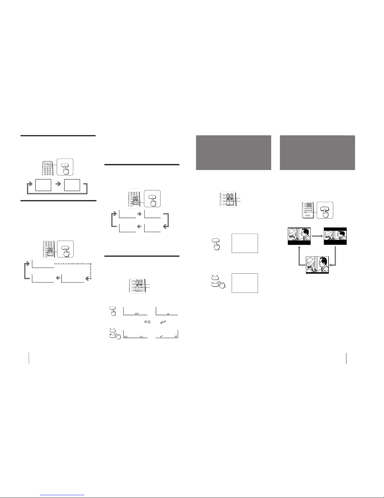
Changing the on-screen display
language
You can use buttons on the remote commander or the
TV to change the on-screen display language.
1
Press SELECT until the screen appears as
follows:
2
Press + or – to select “
” or “ ”.
Note
• You can also use SELECT and VOLUME +/– on the TV to
select the on-screen display language.
• The last TV program position or video input just before the TV
turns into standby mode will appear when the TV is turned on
using the Wake Up Timer.
• If no buttons or controls are pressed for more than two hours
after the TV is turned on using the Wake Up Timer, the TV
automatically turns into standby mode. If you want to
continue watching the TV, press any button or control on the
remote commander or the TV.
1
AUTO B/G
DYNAMIC MUSIC
Displaying on-screen information
Press DISP/REVEAL.
The program position, local system, and TV settings are
displayed on the screen.
No sleep timer
After 90 minutes
After 60 minutes
After 30 minutes
SELECT
LANGUAGE
/
: ENGLISH
LANGUAGE /
: ENGLISH
or
(KV-J21MN1AK)
(KV-J21MN1AK)
(KV-J21MF1AK/J21PF1/
J21MF3)
(KV-J21MF1AK/J21PF1/
J21MF3)
/
LANGUAGE
:
or
: LANGUAGE /
SLEEP TIMER:30M SLEEP TIMER:60M
SLEEP TIMER:OFF
SLEEP TIMER:90M
Setting the Wake Up Timer
You can set the TV to automatically turn on as you have
programmed.
1
Press WAKE UP/INDEX repeatedly to set the
timer.
The on-screen display appears and the WAKE UP
indicator on the TV lights up.
2
If you want a particular TV program or
video input to be displayed using the Wake
Up Timer, select the TV program or video
input.
3
Press POWER on the remote commander or
set the Sleep Timer to turn off the TV in
standby mode.
To cancel the Wake Up Timer, press WAKE UP/INDEX
repeatedly until “WAKE UP TIMER: OFF” appears, or
turn off the main power of the TV.
Notes
• The Wake Up Timer starts immediately after the on-screen
display disappears.
SLEEP
TEXT CLR
WAKE UP
INDEX
After 10 minutes
WAKE UP TIMER:10M
WAKE UP TIMER:OFF
WAKE UP TIMER:12H00M
No wake up timer
After 12 hours
+ or –
SELECT
11
Operations
Using the Child Lock
feature
Watching the picture
in wide mode
You can prevent a child from watching certain program
positions by using the buttons on the remote
commander.
1
Select the TV program you want to lock.
2
Press SELECT until “CHILD LOCK” appears
on the screen.
3
Press + or – until “LOCKED” appears on the
screen.
Notes
• To unlock the program position, repeat steps 1 to 3 as above
until “LOCKED” disappears from the screen.
• To prevent your child from unlocking the program position,
keep the remote commander away from your child.
÷
0
+ or –
SELECT
SELECT
CHILD LOCK
LOCKED
You can adjust the display mode accordingly to fit the
programs to your TV screen size.
Press WIDE/V-ZOOM repeatedly until the wide
display mode you want appears on the screen.
TV
WIDE/
V-ZOOM
Good-bye,Jane
Good-bye.
Good-bye,Jane
Good-bye.
WIDE
V-ZOOM
NORMAL
Normal display
mode “WIDE” mode
“V-ZOOM” mode
– 9 –
KV-J21MF1AK/J21MF3
KV-J21MN1AK/J21PF1
RM-883
Operations
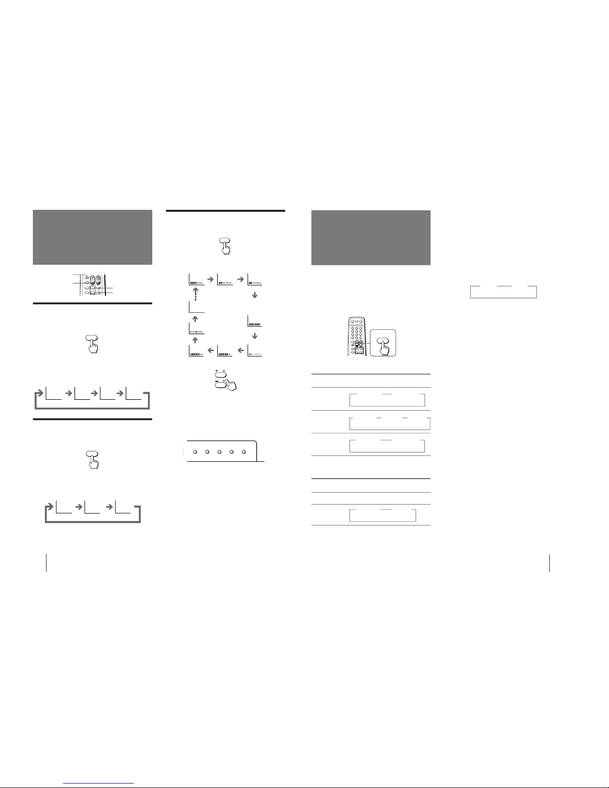
12
Adjusting the
picture
Adjusting the sound and picture settings
1
Press SELECT until the item you want to
adjust appears.
Each time you press SELECT, the screen changes
as follows:
2
Press + or – to adjust the item.
3
To adjust other items, repeat steps 1 and 2.
Notes
• You can also use SELECT and VOLUME +/– on the TV to
adjust the sound and picture settings.
• SURROUND is only applicable to a stereo signal. When
receiving a monaural signal, please turn off SURROUND for
the best sound.
If the picture color is abnormal when receiving
programs through the ˘ (antenna) terminal
Change the “TV SYSTEM” (for KV-J21MF1AK/J21MN1AK/
J21MF3 only) or “COLOR SYSTEM” setting or adjust the “COLOR”
level in the on-screen display until the color becomes normal.
If the picture color is abnormal when receiving
programs through the video input jack
Change the “COLOR SYSTEM” setting or adjust the “COLOR”
level in the on-screen display until the color becomes normal.
Note
• Normally set “COLOR SYSTEM” to “AUTO”.
If the sound is distorted or noisy when receiving
programs through the ˘ (antenna) terminal
Change the “TV SYSTEM” setting (for KV-J21MF1AK/
J21MN1AK/J21MF3 only) in the on-screen display until the
sound becomes clear.
Adjusting the sound
and picture
÷
0
SOUND
MODE
SELECT
PIC MODE
Selecting the sound mode
Press SOUND MODE until the mode you want
appears.
Each time you press SOUND MODE, the screen
changes as follows:
Selecting the picture mode
Press PIC MODE until the mode you want
appears.
Each time you press PIC MODE, the screen changes as
follows:
Note
• If you change the picture and sound mode after the following
adjustments, the adjustment changes in accordance with the
picture and sound mode.
MUSIC
DRAMA SPORTS
SOFT
Emphasize
low and high
sound effect
Emphasize
huge
audience
atmosphere
Emphasize
vocals and
background
music
Emphasize
soft sound
Front of TV
SOUND
MODE
High contrast
picture
DYNAMIC
STANDARDSOFT
Normal
picture
PIC MODE
Soft picture
PICTURE
COLOR BRIGHT
HUE
SHARPNESS
BASS
BALANCE
SURROUND
TREBLE
SELECT
MANUAL PROGR
COLOR SYSTEM
SELECT
TV SYSTEM
AUTO PROGR
+ or –
(Operative for
NTSC signal only)
13
Operations
A/B
ENLARGE
Selecting a stereo or
bilingual program
p KV-J21MN1AK only
Press A/B/ENLARGE repeatedly until you
receive the sound you want.
The on-screen display changes corresponding to the
selected sound and the WAKE UP/STEREO indicator
also lights up.
When receiving a NICAM program
Broadcasting
NICAM stereo
NICAM bilingual
NICAM monaural
When receiving an A2 (German) program
Broadcasting
A2 (German)
stereo
A2 (German)
bilingual
Notes
• If the signal is very weak, the sound becomes monaural
automatically.
• If the stereo sound is noisy when receiving a NICAM program,
select “MONO”. The sound becomes monaural, however, the
noise will be reduced.
If the sound is distorted or noisy when
receiving a monaural program through the
˘
(antenna) terminal
Press A/B/ENLARGE repeatedly until “MONO”
appears on the screen.
To cancel the monaural sound setting, press
A/B/ENLARGE again until “AUTO” appears on the
screen.
Notes
• The “MONO” or “AUTO” setting is memorized for each
program position.
• You cannot receive stereo signal when the TV is in the
“MONO” setting.
On-screen display
(Selected sound)
NICAM
z(Stereo sound)
MONO
z (Regular sound)
NICAM
z MAIN
(Main sound)
NICAM
z SUB
(Sub sound)
NICAM
z MAIN
(Main sound)
MONO
z (Regular sound)
MONO
z (Regular
sound)
On-screen display
(Selected sound)
STEREO
(Stereo sound)
z MAIN
(Main sound)
z SUB
(Sub sound)
z MONO
z AUTO
– 10 –
KV-J21MF1AK/J21MF3
KV-J21MN1AK/J21PF1
RM-883
Additional Information
14
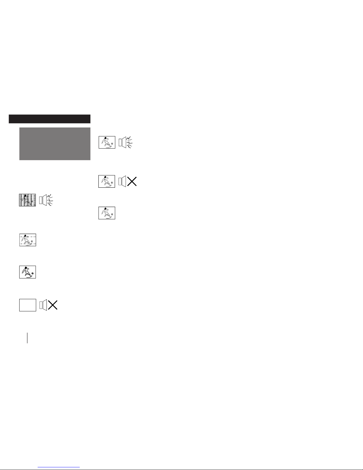
Troubleshooting
Additional Information
If you have any problems, read this manual again and
check the countermeasure for each of the symptoms
listed below.
If the problem persists, contact your nearest authorized
service center or dealer.
Snowy picture
Noisy sound
/Check the antenna.
/Check the antenna connection on the TV
and on the wall.
/Check the TV SYSTEM setting
(KV-J21MF1AK/J21MN1AK/J21MF3 only).
Dotted lines or stripes
/This may be caused by local interference
(e.g. cars, neon signs and hair dryers). Adjust
the antenna for minimum interference.
Double images or “ghosts”
/This may be caused by reflections from
nearby mountains or buildings. A highly
directional antenna may improve the picture.
No picture
No sound
/Press POWER.
/Check the antenna connection.
/Check the VCR connections.
/Check the power cord connection.
/Check the standby mode.
Good picture
Noisy sound
/Check the TV SYSTEM setting (KV-
J21MF1AK/J21MN1AK/J21MF3 only).
/Reduce the TREBLE level or select the
“SOFT” sound mode.
Good picture
No sound
/Press VOLUME +.
/Press MUTING.
/Press A/B/ENLARGE
(KV-J21MN1AK).
No color
/Adjust the COLOR level in the on-screen
display.
/Check the COLOR SYSTEM setting.
TV cannot receive stereo signal
/Press A/B/ENLARGE until “AUTO”
appears
on the screen (KV-J21MN1AK).
TV cabinet creaks
/Even if the picture or the sound is normal,
changes in the room temperature
sometimes make the TV cabinet expand or
contract, making a noise. This does not
indicate a malfunction.
Note on the remote commander
• The supplied remote commander is used on several models of
the TV. If you do not find instructions for some controls that
are on the remote commander, that means your TV does not
employ the features of those controls, e.g. TEXT.
Note on the TV SYSTEM button
• The TV SYSTEM button is not used on your TV (KV-J21PF1
only).
Notes
• When you switch on the TV, you may hear the “boon” sound
that is caused by the demagnetization of the TV. This does not
indicate a malfunction.
• The picture color may become abnormal if you change the
direction of your TV. To obtain the normal picture color, press
POWER on the TV to switch off the TV for five minutes and
then switch it on again.
WARNING
Do not install the appliance in a confined space, such as
a bookcase or built-in cabinet.
– 11 –
KV-J21MF1AK/J21MF3
KV-J21MN1AK/J21PF1
RM-883
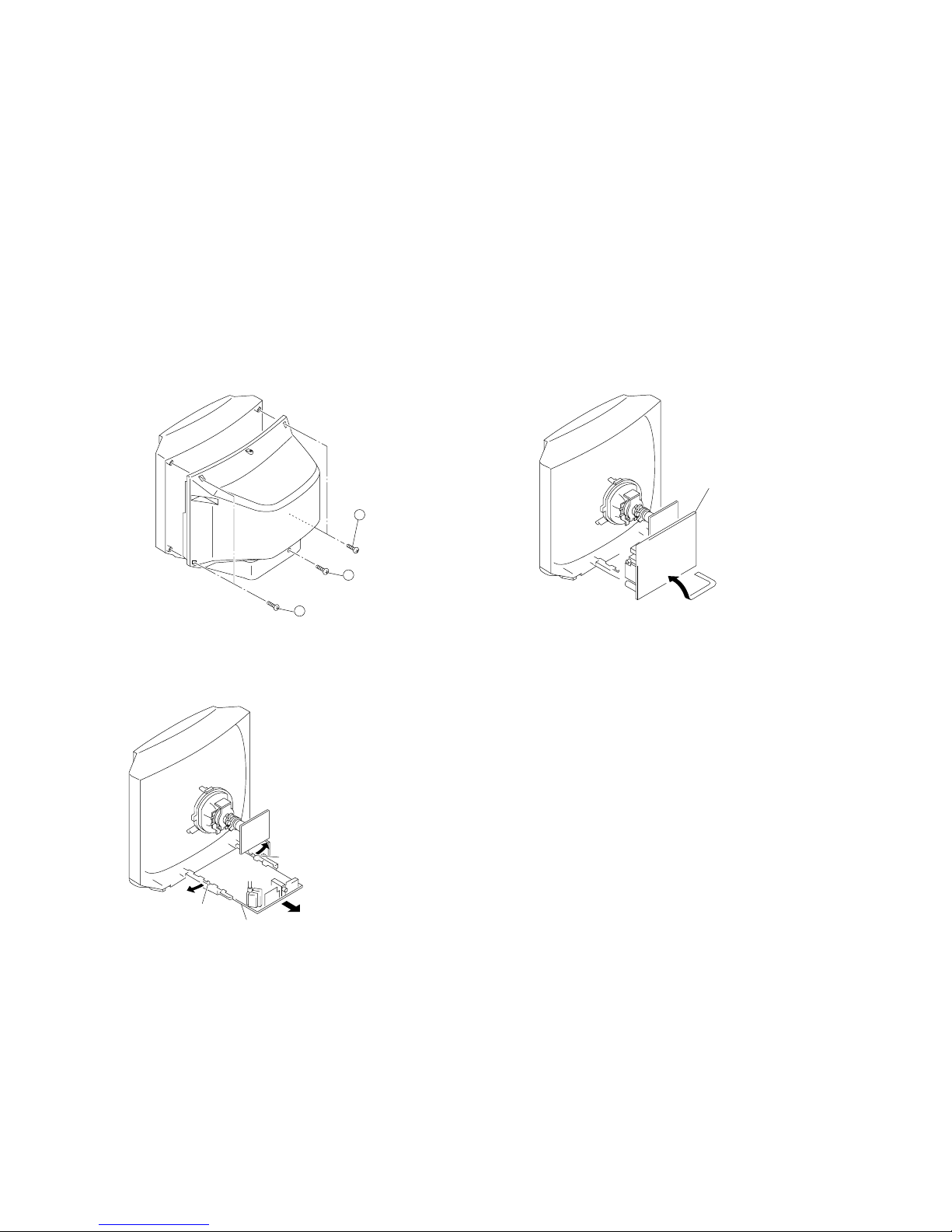
2-1. REAR COVER REMOVAL
2-2. A BOARD REMOVAL
2-3. SERVICE POSITION
SECTION 2
DISASSEMBLY
A board
Lever
Lever
A board
2
Two screws
(BVTP 4×16)
3
One screw
(BVTP 3×16)
1
Two screws
(BVTP 4×16)
– 12 –
KV-J21MF1AK/J21MF3
KV-J21MN1AK/J21PF1
RM-883
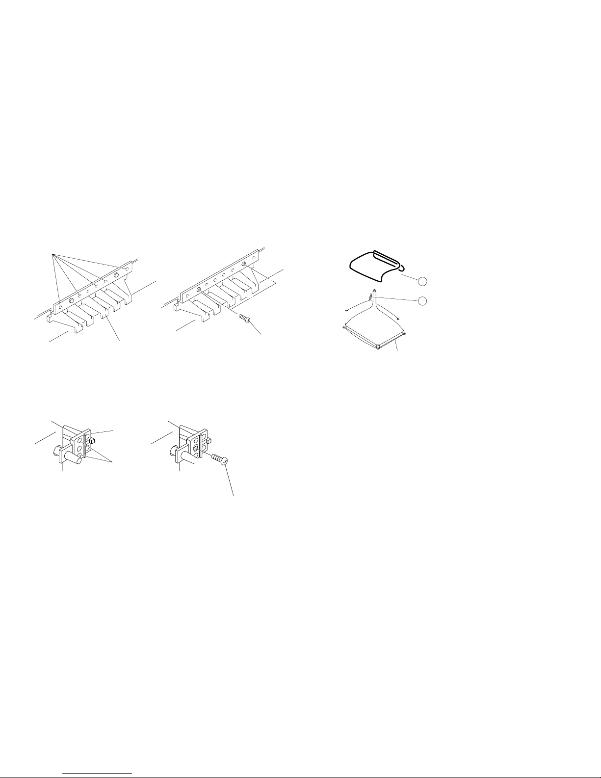
2-4. REPLACEMENT OF PARTS
For replacement of the Multi Button, Power Button and Light Guide, cut the welded portions
from them, exchange with the new parts, and fix them with screws (+BVTP) respectively.
2-4-1. REPLACEMENT OF MULTI BUTTON
2-4-2. REPLACEMENT OF LIGHT GUIDE
2-5. DEMAGNETIZATION COIL REMOVAL
1
Demagnetization coil
2
Tension spring
Picture tube
Cut
Multi button
Two screws
(BVTP 3×12)
Light guide
Cut
One screw
(BVTP 3×12)

– 13 –
KV-J21MF1AK/J21MF3
KV-J21MN1AK/J21PF1
RM-883
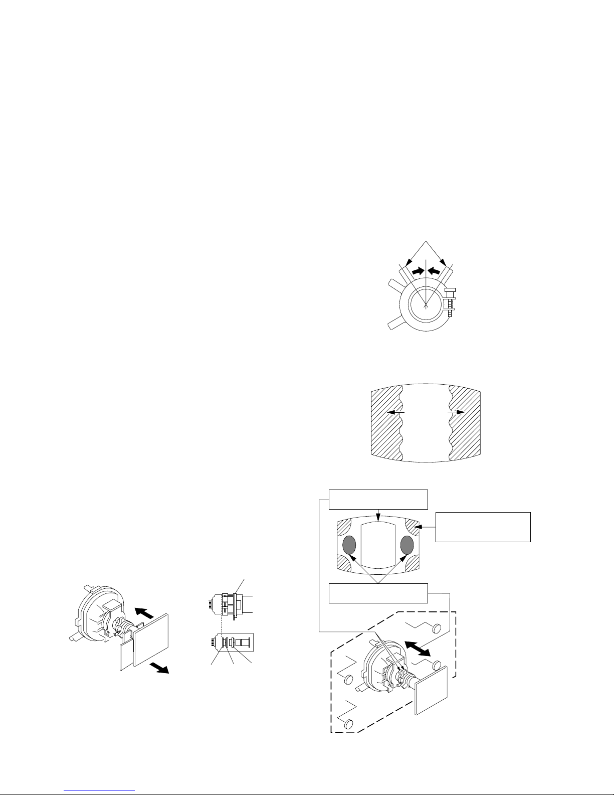
2-6. PICTURE TUBE REMOVAL
2 Using a thumb press down, then pull up the rubber cap firmly in the direction
indicated by the arrow b.
3 When one side of the rubber cap is separated from the anode button, the anode-
cap can be removed by turning up the rubber cap and pulling it up in the direction of the arrow c.
• HOW TO HANDLE AN ANODE-CAP
1 Do not damage the surface of anode-cap with sharp shaped objects.
2 Do not press the rubber too hard so as not to damage the inside of anode-cap.
A metal fitting called the shatter-hook terminal is built into the rubber.
3 Do not turn the foot of rubber over too hard.
The shatter-hook terminal will stick out or damage the rubber.
•REMOVAL OF ANODE-CAP
NOTE : After removing the anode, short circuit the anode of the picture tube and the an-
ode cap to the metal chassis, CRT shield or carbon paint on the CRT.
•REMOVING PROCEDURES
1 Turn up one side of the rubber cap in the direction indicated by the arrow a.
2 A board
3 C board
4 Deflection yoke
Cushion
5 Four screws
(Tapping screws)
1 Anode cap
6 VM board
(Except for KV-J21PF1)
a
a
b
b
c
Anode button
– 14 –
KV-J21MF1AK/J21MF3
KV-J21MN1AK/J21PF1
RM-883
• The following adjustments should be made when a complete
realignment is required or a new picture tube is installed.
• These adjustments should be performed with rated power
supply voltage unless otherwise noted.
Controls and switch should be set as follows unless otherwise noted:
PICTURE control........................................................... normal
BRIGHTNESS control................................................... normal
Perform the adjustments in the following order:
1. Beam Landing
2. Convergence
3. Focus
4. White Balance
Note : Test Equipment Required:
1. Color-bar/Pattern Generator
2. Degausser
3. Oscilloscope
SECTION 3
SET-UP ADJUSTMENTS
.................................................................................................................................................................................................................................
Fig. 3-4
Fig. 3-3
GREEN
BLUE RED
Fig. 3-2
Purity control
}
normal
Preparation :
• In order to reduce the influence of geomagnetism on the set's
picture tube, face it east or west.
• Switch on the power and degauss with the degausser.
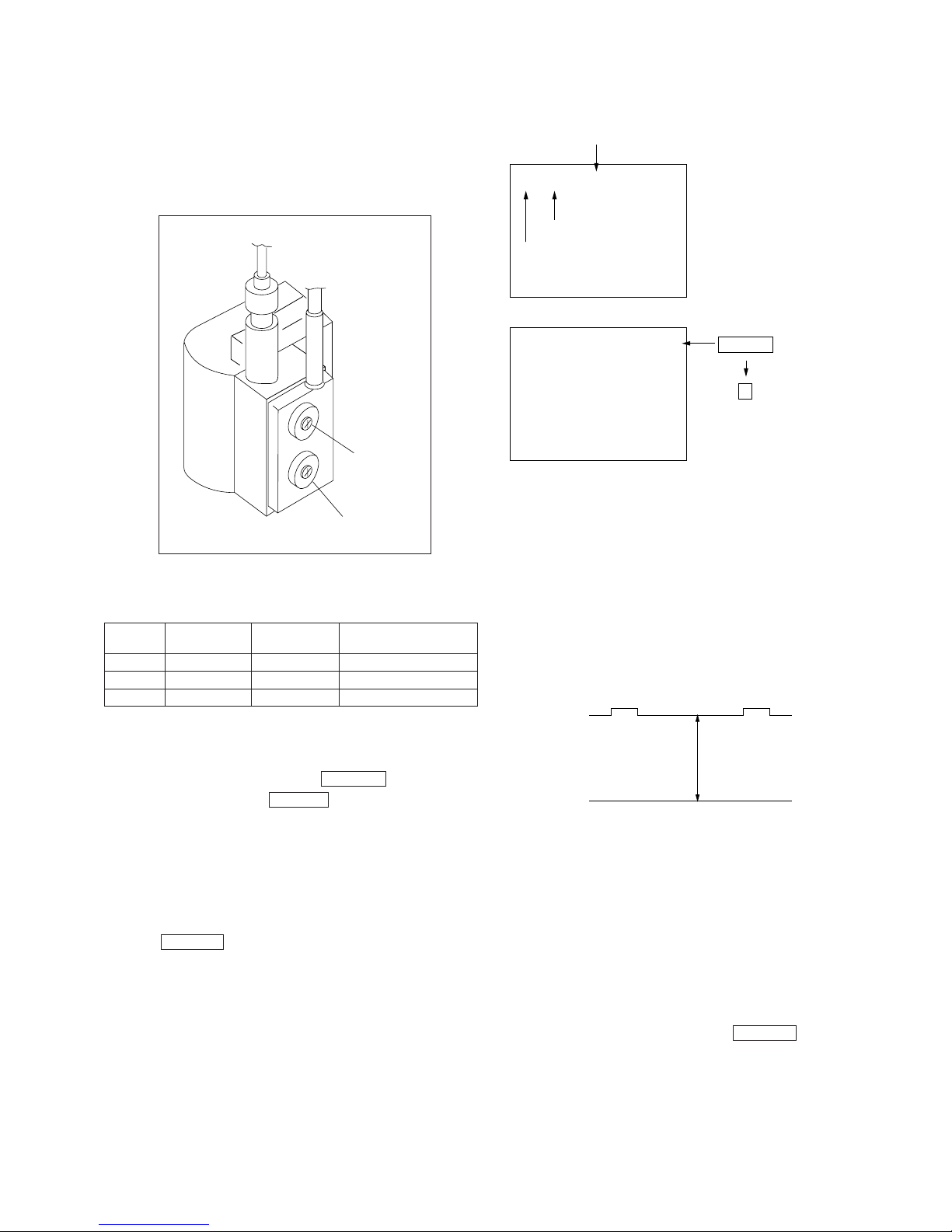
3-1. BEAM LANDING
1. Input a white signal with the pattern generator.
Contrast
Brightness
2. Position neck assy as shown in Figure 3-1. (Except for KVJ21PF1)
3. Set the pattern generator raster signal to green.
4. Move the deflection yoke to the rear and adjust with the purity
control so that the green is at the center and the blue and the red
take up equally sized areas on each side.
(See Figures 3-1 through 3-3.)
5. Move the deflection yoke forward and adjust so that entire
screen is green. (See Figure 3-1.)
6. Switch the raster signal to blue, then to red and verify the
condition.
7. When the position of the deflection yoke has been decided,
fasten the deflection yoke with the screws.
8. If the beam does not land correctly in all the corners, use a
magnet to adjust it. (See Figure 3-4.)
Deflection yoke positioning
corrects these areas.
Purity control corrects
this area.
Disk magnets or rotatable
disk magnets correct
these areas (a-d).
b
c
a
d
ba
c
d
Neck assy
G1 G2 G3
Fig. 3-1
– 15 –
KV-J21MF1AK/J21MF3
KV-J21MN1AK/J21PF1
RM-883
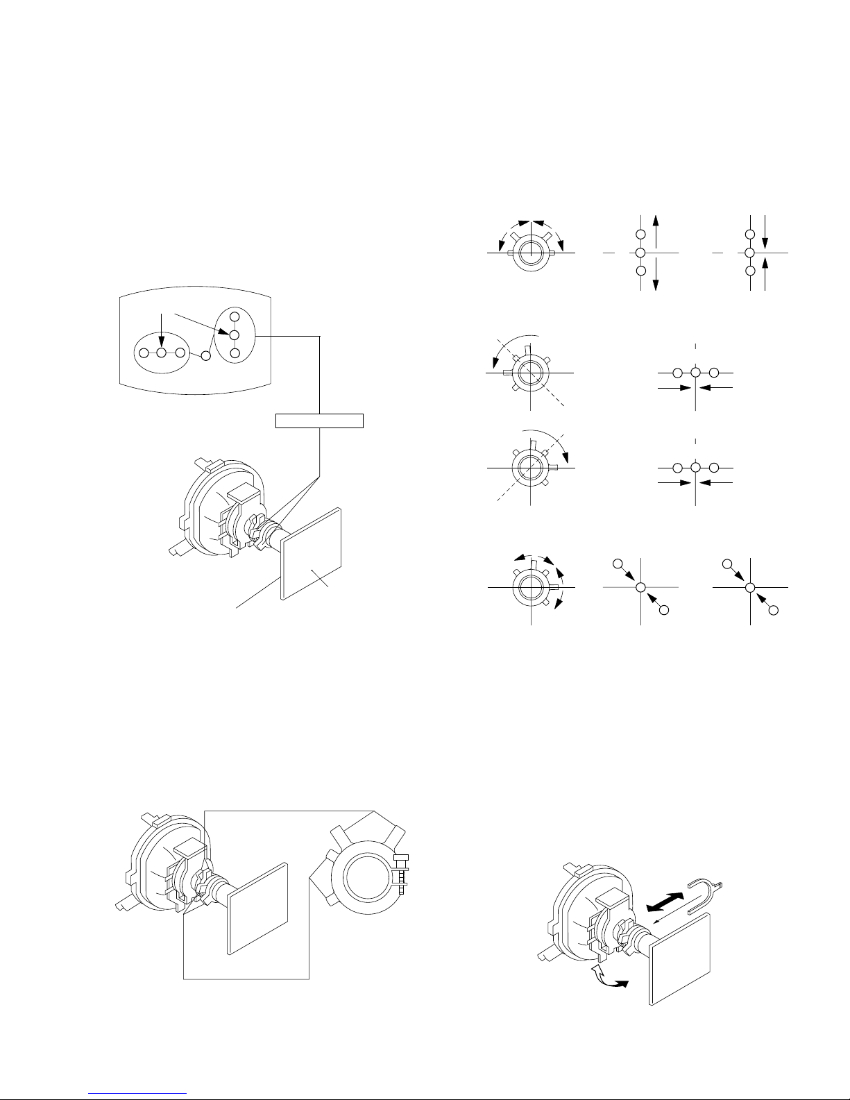
3-2. CONVERGENCE
Preparation :
• Before starting this adjustment, adjust the focus, horizontal size,
and vertical size.
• Minimize the brightness setting.
• Provide dot pattern.
(1) Horizontal and Vertical Static Convergence
1. (Moving vertically), adjust the V.STAT magnet so that the red,
green and blue dots are on top of each other at the center of the
screen.
2. (Moving horizontally), adjust the H.STAT VR so that the red,
green and blue dots are on top of each other at the center of the
screen.
• Operation of V.STAT magnet.
If the V.STAT magnet is moved in the direction of the a and
b arrows, the red, green and blue dots move as shown below.
B
R
B
R
ab
bb
a
b
a
b
a
R
G
B
b
B
G
R
b
b
a
a
1
2
3
GG
B G R
R G B
R G B
G
R
B
Center dot
V.STAT Magnet
C board
RV 701
SCREEN (G2)
V.STAT
Purity
• Operation of BMC (Hexapole) magnet.
If the blue or red dot does not conver ge with the other two dots,
perform following steps.
Move BMC magnet (a) to correct insufficient H.static
convergence.
Rotate BMC magnet (b) to correct insufficient V.static
convergence.
In either case, repeat Beam Landing Adjustment.
a
BMC magnet
b

– 16 –
KV-J21MF1AK/J21MF3
KV-J21MN1AK/J21PF1
RM-883
3. Move the deflection yoke as shown in the figure below and
optimize the convergence.
4. Tighten the deflection yoke screws.
5. Install the deflection yoke spacer.
(3) Screen-corner Convergence
a-d : screen-corner
misconvergence
b
a
c
d
(2) Dynamic Convergence Adjustment
Preparation :
• Before starting this adjustment, adjust the horizontal static
convergence and the vertical static convergence.
1. Slightly loosen the deflection yoke screws.
2. Remove the deflection yoke spacer.
B G R
B
G
R
R
G
B
R G B
R G B
R
G
B
B
G
R
B G R
R G BB G R
B G RR G B
a
d
c
b
Fix a Permalloy assy
corresponding to the
misconverged areas
Permalloy assembly
– 17 –
KV-J21MF1AK/J21MF3
KV-J21MN1AK/J21PF1
RM-883
3-3. FOCUS ADJUSTMENT
Adjust FOCUS control on the flyback transformer for the best
focus.
Note: Screen VR is not use.
a. AN ITEM OF ADJUSTMENT
b. METHOD OF CANCELLATION FROM SERVICE
MODE
Set the standby condition (Press POWER button on the
commander) and then press POWER button again, hereupon it
becomes TV mode.
c. METHOD OF WRITE FOR MEMORY
1) Set to Service Mode.
2) Press 1 (UP) and 4 (DOWN) to select an item of adjustments.
3) Press MUTING button and it will indicate WRITE on screen.
4) Press - button to write into memory.
d. MEMORY WRITE CONFIRMATION METHOD
1) After adjustment, pull out the plug from AC outlet, and then
plug into AC outlet again.
2) Turn the power switch ON and set to Service Mode.
3) Call the adjusted items again, confirm they were adjusted.
NoteInitial DATA
09 RDR 28 WHITE POINT R
0A GDR 20 WHITE POINT G
0B BDR 20 WHITE POINT B
3-4. G2 (SCREEN) AND WHITE BALANCE
ADJUSTMENTS
1. G2 (SCREEN) ADJUSTMENT (RV701)
1) Set the PICTURE and BRIGHTNESS to normal.
2) Put to VIDEO input mode without signals.
3) Connect R, G and B of the C board cathode to the oscilloscope.
4) Adjust G2 (RV701) volume to the value below.
2. WHITE BALANCE ADJUSTMENTS
1) Set to Service Mode.
2) Input an entire white signal.
3) Set the PICTURE to maximum.
4) Select RDR(09) with 1 and 4 , and then set the level to 28
with 3 and 6 .
5) Select GDR(0A) and BDR(0B) with 1 and 4 and adjust
the level with 3 and 6 for the best white balance.
6) Write into the memory by pressing MUTING , then - .
SERVICE
MUTING
1 F
DATA
RDR
Adjustment Item
09
Item number
WRITE1 FRDR09
0
Executes the writing
Item
number
Adjustment
item
FOCUS
SCREEN
(NOT USED)
0 V
177 ± 2 V DC
 Loading...