

Sony Trinitron KV-ES34K90 Service Manual
http://cxema.ru
SERVICE MANUAL
AG3
CHASSIS
MODEL COMMANDER DEST. CHASSIS NO.
KV-ES34K90 RM-959 KOREAN SCC-P41B-A
MODEL COMMANDER DEST. CHASSIS NO.
MUTING
DISPLAY DRC-MF POWER
MTS VIDEO
JUMP
TV/VIDEO
TWIN
ZOOM
IN
LEFT
FAVORITE
SOUND
SURROUND WAKE UP
MODE
PIC
MODE
231
564
897
0
FREEZE SWAP PIP
PIP CH
PIP CH
CHVOL
TV
TV
ENTER
MENU
ZOOM
IN
RIGHT
CH
INDEX
SLEEP
VIDEO
POWER
TITLE
TRINITRON
®
COLOR TV

http://cxema.ru
KV -ES34K90
RM-959
Power requirements 110-220 V AC, 60 Hz
Power consumption (W) Indicated on the rear of the TV
Television system M
Color system NTSC3.58
Stereo/Bilingual system Korean Stereo
Channel coverage
˘ (Antenna) 75-ohm external terminal
Audio output (Speaker) 15W + 15W 10% distortion
Number of terminal
Video Input: 4 Output: 1 Phono jacks; 1 VP-P, 75 ohms
Audio Input: 4 Output: 1 Phono jacks; 500 mVrms
S Video Input: 2 Y : 1 Vp-p, 75 ohms,
Component Video
(DVD) IN
DIGITAL IN Input: 1 Phono jack; 0.5 Vp-p, 75 ohms
2 (Headphones) Output: 1 Stereo minijack
Picture tube 34 inch
Tube size (cm) 86 Measured diagonally
Screen size (cm) 80 Measured diagonally
Dimension (w/h/d, mm) 859 x 650 x 573
Mass (kg) 84
SPECIFICATIONS
VHF: 2 ch to 13 ch / UHF: 14 ch to 69 ch / CATV: 1 ch to 125 ch
unbalanced, sync
negative
C : 0.286 Vp-p, 75 ohms
Input: 1 Phono jacks
Y : 1 Vp-p, 75 ohms,
sync negative
C
B : 0.7 Vp-p, 75 ohms
R : 0.7 Vp-p, 75 ohms
C
Audio : 500 mVrms
Note
CAUTION
SHORT CIRCUIT THE ANODE OF THE PICTURE TUBE AND
THE ANODE CAP TO THE METAL CHASSIS, CRT SHIELD, OR
CARBON PAINTED ON THE CRT, AFTER REMOVING THE
ANODE.
Design and specifications are subject to change without notice.
SAFETY-RELATED COMPONENT WARNING!!
COMPONENTS IDENTIFIED BY SHADING AND MARK ! ON
THE SCHEMA TIC DIA GRAMS, EXPLODED VIEWS AND IN THE
PARTS LIST ARE CRITICAL TO SAFE OPERATION. REPLACE
THESE COMPONENTS WITH SONY PARTS WHOSE PART
NUMBERS APPEAR AS SHOWN IN THIS MANUAL OR IN
SUPPLEMENTS PUBLISHED BY SONY.
– 2 –

http://cxema.ru
TABLE OF CONTENTS
KV-ES34K90
RM-959
Section Title Page
SELF DIAGNOSIS FUNCTION................................ 4
1. GENERAL........................................................................ 8
2. DISASSEMBLY
2-1. Rear Cover Removal................................................ 32
2-2. Speaker Box Removal ............................................. 32
2-3. H2 Board Removal .................................................. 32
2-4. Chassis Assy Removal ............................................. 33
2-5. Service Position ....................................................... 33
2-6. DH Board Removal ................................................. 33
2-7. J Board Removal...................................................... 33
2-8. B3, D1 and E Boards Removal................................ 34
2-9. A and D Boards Removal ........................................ 34
2-10. H1 Board Removal .................................................. 34
2-11. F2 Board Removal ................................................... 34
2-12. Demagnetization Coil Removal .............................. 35
2-13. Top Switch Removal CH3 Board Removal............. 35
2-14. G2 Lead Removal .................................................... 35
2-15. Picture Tube Removal.............................................. 36
2-16. Frame Sub-Assy Disassembly ................................. 36
3. SERVICE JIG
3-1. Jig Required for Servicing....................................... 39
4. SET-UP ADJUSTMENTS
4-1. Beam Landing .......................................................... 40
4-2. Convergence Adjustment......................................... 41
4-3. Focus Adjustment .................................................... 43
4-4. Neck Assy Twist Adjustment................................... 43
4-5. G2 (Screen) and White Balance Adjustments ......... 44
Section Title Page
6. DIAGRAMS
6-1. Block Diagram ......................................................... 67
6-2. Frame Schematic Diagram ..................................... 85
6-3. Circuit Boards Location ......................................... 88
6-4. Schematic Diagrams and Printed Wiring Boards .. 88
(1) Schematic Diagram of A Board ............................. 93
(2) Schematic Diagram of D Board ............................. 97
(3) Schematic Diagram D1 Board............................... 105
(4) Schematic Diagrams of C, F1 and VM Boards...... 113
(5) Schematic Diagram of E Board.............................. 117
(6) Schematic Diagrams of H1, H2 and H3 Boards ....124
(7) Schematic Diagram of B3 (1/6) Board .................. 129
(8) Schematic Diagram of B3 (2/6) Board .................. 133
(9) Schematic Diagram of B3 (3/6) Board .................. 137
(10) Schematic Diagram of B3 (4/6) Board .................. 141
(11) Schematic Diagram of B3 (5/6) Board .................. 145
(12) Schematic Diagrams of B3 (6/6) and F2 Boards ... 149
(13) Schematic Diagram of DH Board .......................... 153
(14) Schematic Diagram of A1 Board ........................... 159
(15) Schematic Diagram of BC4 Board......................... 163
(16) Schematic Diagram of J Board............................... 173
6-5. Semiconductors....................................................... 177
7. EXPLODED VIEWS
7-1. Speaker Bracket ...................................................... 181
7-2. Chassis .................................................................... 182
7-3. Picture Tube ............................................................ 183
8. ELECTRICAL PARTS LIST...................................... 184
5. CIRCUIT ADJUSTMENTS
5-1. Adjustments with Commander ................................ 45
5-2. Adjustment Method ................................................. 46
5-3. Picture Quality Adjustments.................................... 60
5-4. Deflection Adjustment ............................................. 62
5-5. A Board Adjustment After IC003
(memory) Replacement ........................................... 63
5-6. Picture Distortion Adjustment................................. 64
– 3 –

http://cxema.ru
KV -ES34K90
RM-959
SELF DIAGNOSTIC FUNCTION
The units in this manual contain a self-diagnostic function. If an error occurs, the STANDBY/TIMER lamp will automatically
begin to flash.
The number of times the lamp flashes translates to a probable source of the problem. A definition of the STANDBY/TIMER
lamp flash indicators is listed in the instruction manual for the user’s knowledge and reference. If an error symptom cannot
be reproduced, the remote commander can be used to review the failure occurrence data stored in memory to reveal past
problems and how often these problems occur.
1. DIAGNOSTIC TEST INDICA TORS
When an errors occurs, the STANDBY/TIMER lamp will flash a set number of times to indicate the possible cause of the
problem. If there is more than one error, the lamp will identify the first of the problem areas.
Result for all of the following diagnostic items are displayed on screen. No error has occured if the screen displays a “0”.
Diagnostic
Item
Description
• Power does not
turn on
• +B overcurrent
(OCP)
• +B overvoltage
(OVP)
• Vertical deflection
failure
• White balance
failure (no
PICTURE)
• Horizontal
deflection
failure
• Audio Protection
• Micro reset
No. of times
STANDBY/TIMER
lamp flashes
Does not light
2 times
3 times
4 times
5 times
6 times
7 times
—
Self-diagnostic
display/Diagnostic
result
—
002:000 or
002:001~255
003:000 or
003:001~255
004:000 or
004:001~255
005:000 or
005:001~255
006:000 or
006:001~225
007:000 or
007:001~225
101:00 or
101:001~225
Probable
Cause
Location
• Power cord is not plugged
in.
• Fuse is burned out F1601
(F1 Board)
• H.OUT Q6807 is shorted.
• H.LIM Q6810 is shorted.
• PH 6602 faulty.
• 10.5V is not supplied.
(D board)
• V.OUT IC6800 faulty
D6816 faulty
D6817 faulty
D6824 faulty
R6852 open
R6851 open
• G2 is improperly adjusted.
(Note 2)
• CRT problem.
• Video OUT IC9001, 9002,
9003 are faulty. (C board)
• IC8306 (J board) and
IC4301 (E board) are faulty.
• No connection E board to C
board.
• C6831 is open circuit.
• CN6101 (D1 board) is
disconnected.
• Power supply fails.
• IC1203, IC1204 faulty
• Discharge CRT (C Board)
• Static discharge
• External noise
Detected
Symptoms
• Power does not come on.
• No power is supplied to the
TV.
• AC power supply is faulty.
• Power does not come on.
• Load on power line is
shorted.
• Power does not come on.
• Vertical deflection pulse is
stopped.
• Vertical size is too small.
• Vertical deflection stopped.
• No raster is generated.
• CRT cathode current
detection reference pulse
output is small.
• H pulse output is too high.
• There is picture but speaker
does not release sound.
• Power is shut down shortly,
after this return back to
normal.
• Detect Micro latch up.
Note 1: Refer to screen (G2) Adjustment in section 4-5 of this manual.
– 4 –
http://cxema.ru
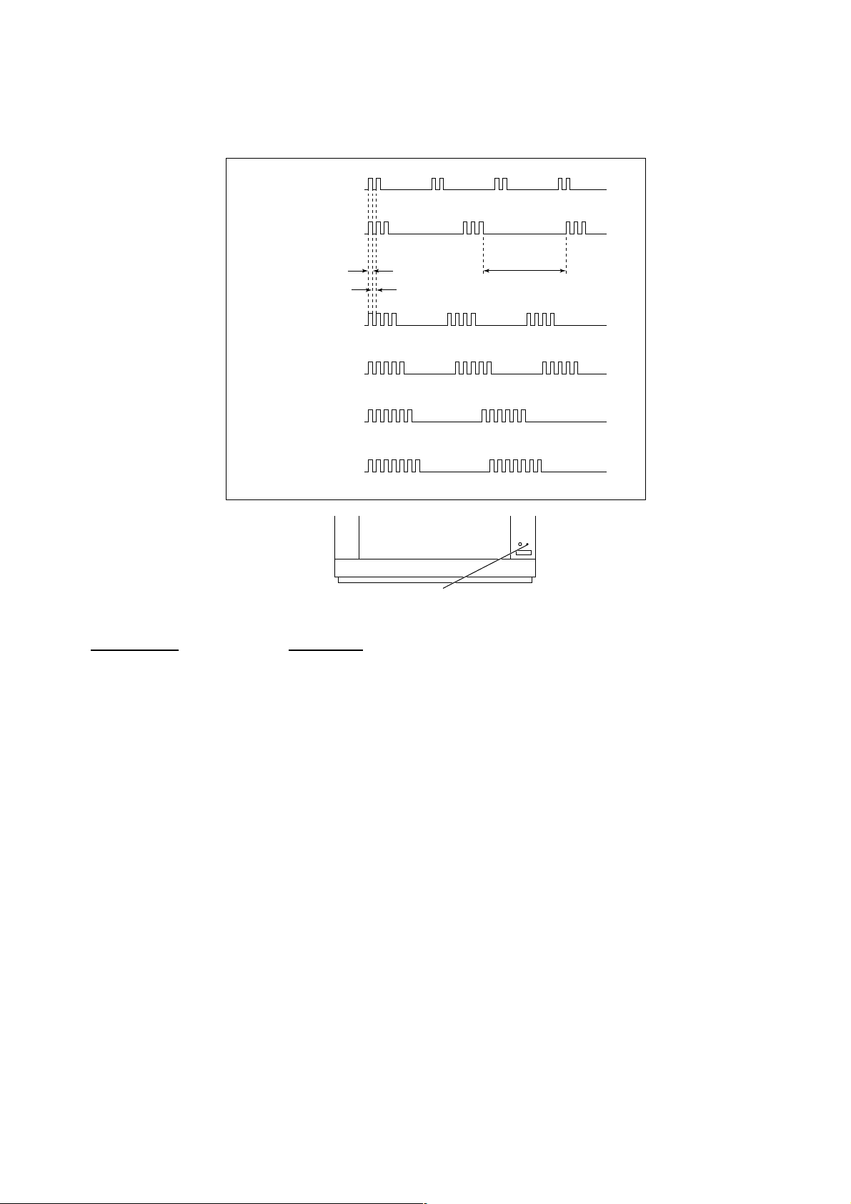
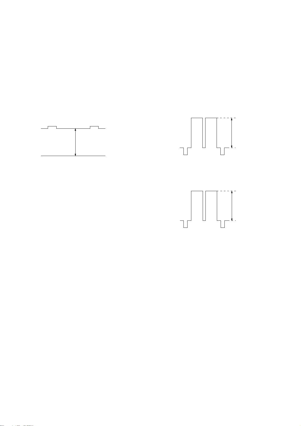
2. DISPLAY OF STANDBY/TIMER LIGHT FLASH COUNT
2 times
3 times
KV-ES34K90
RM-959
Lamp ON 0.3 sec.
Lamp OFF 0.3 sec.
4 times
5 times
6 times
7 times
Diagnostic Item Flash Count*
+B overcurrent 2 times
+B overvoltage 3 times
V deflection stop 4 times
White balance failure 5 times
High voltage protector 6 times
Audio Protection 7 times
Lamp OFF 3 sec.
STANDBY/SLEEP lamp
* One flash count is not used for self-diagnostic.
3. STOPPING THE STANDBY/TIMER FLASH
Turn off the power switch on the TV main unit or unplug the power cord from the outlet to stop the STANDBY/TIMER lamp
from flashing.
– 5 –
http://cxema.ru
KV -ES34K90
RM-959
4. SELF-DIAGNOSTIC SCREEN DISPLAY
For errors with symptoms such as “power sometimes shuts off” or “screen sometimes goes out” that cannot be confirmed, it
is possible to bring up past occurances of failure for confirmation on the screen:
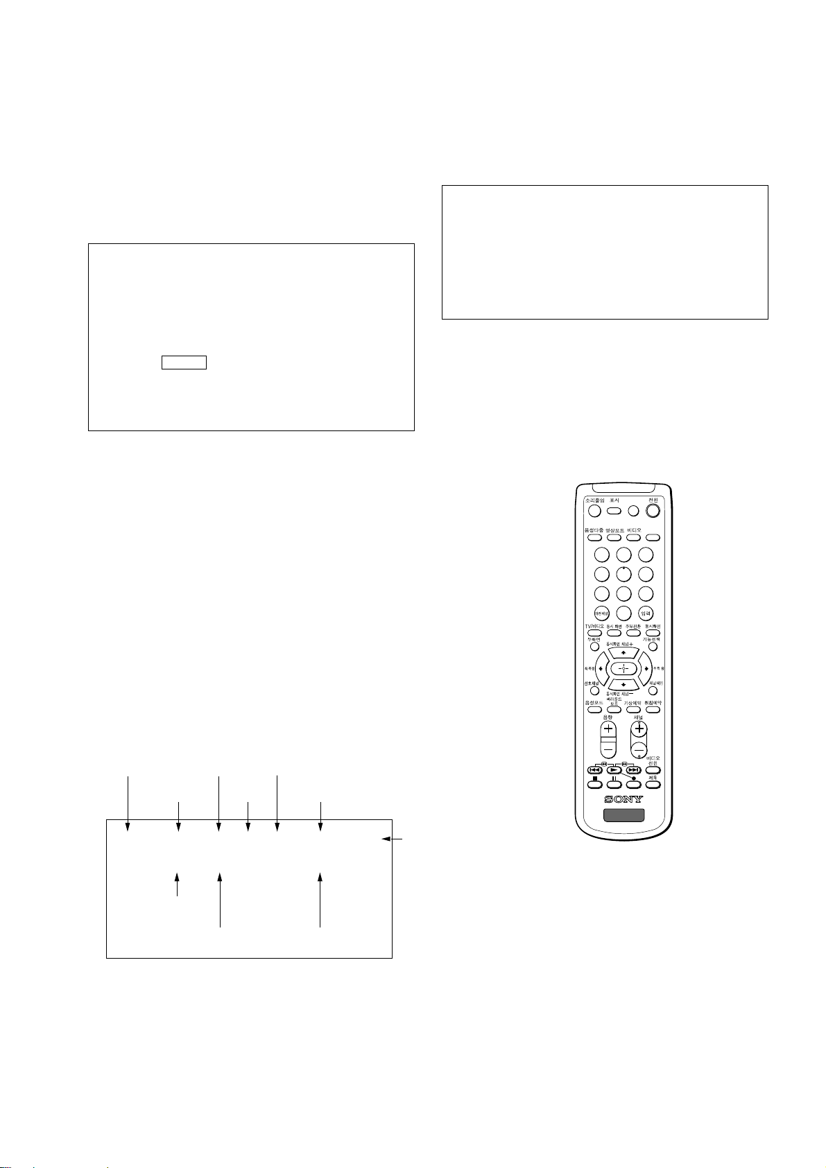
[To Bring Up Screen Test]
In standby mode, press buttons on the remote commander sequentially in rapid succession as shown below:
[Screendisplay] / channel [5] / Sound volume [-] / Power ON
˘
Note that this differs from entering the service mode (mode volume [+]).
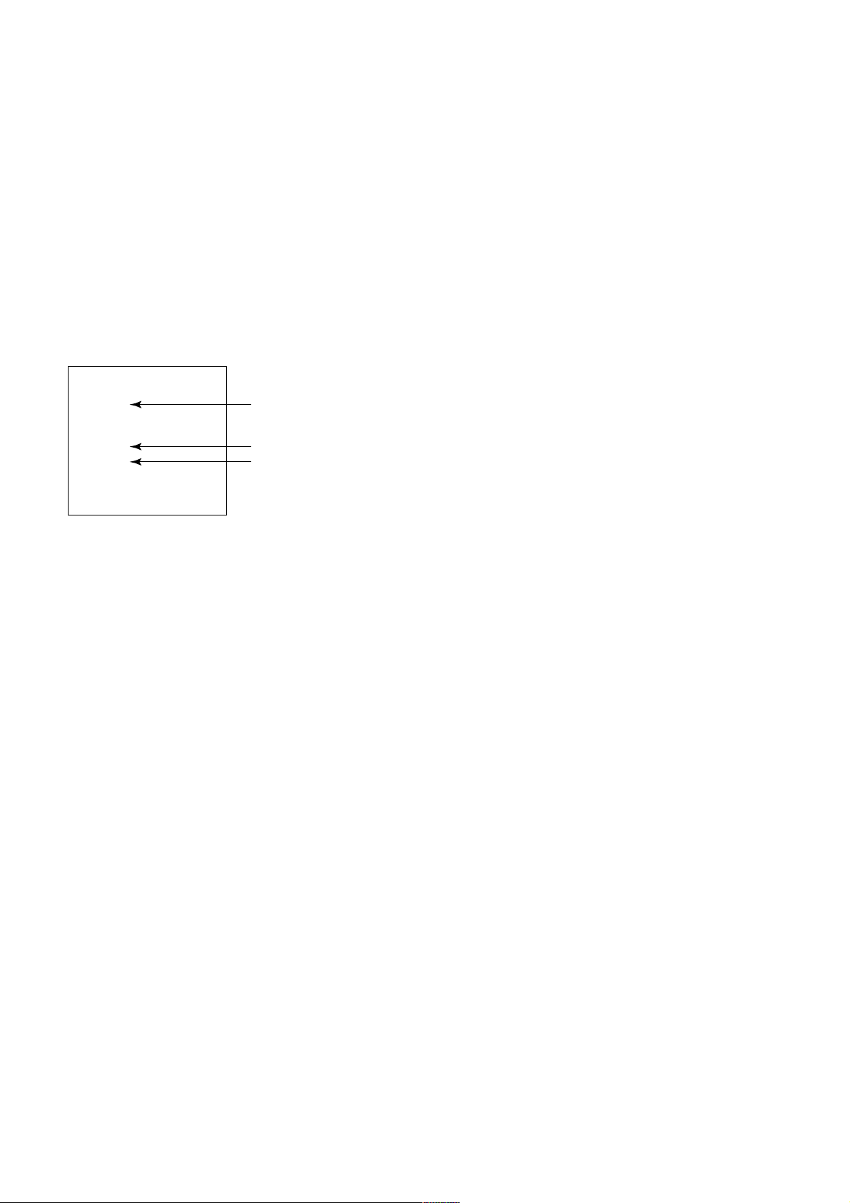
Self-Diagnosis screen display
SELF DIAGNOSTIC
002 : 000
003 : 000
004 : 000
005 : 001
006 : 002
007 : 000
101 : 000
Numeral "0" means that no fault has been detected.
Numeral "1" means a fault has been detected.
Numeral "2" means two faults have been detected.
5. HANDLING OF SELF-DIAGNOSTIC SCREEN DISPLAY
Since the diagnostic results displayed on the screen are not automatically cleared, always check the self-diagnostic screen
during repairs. When you have completed the repairs, clear the result display to “0”.
Unless the result display is cleared to “0”, the self-diagnostic function will not be able to detect subsequent faults after
completion of the repairs.
[Clearing the result display]
To clear the result display to “0”, press buttons on the remote commander sequentially as shown below when the diagnostic
screen is being displayed.
Channel [8] / 0
[Quitting Self-diagnostic screen]
To quit the entire self-diagnostic screen, turn off the power switch on the remote commander or the main unit.
– 6 –
http://cxema.ru
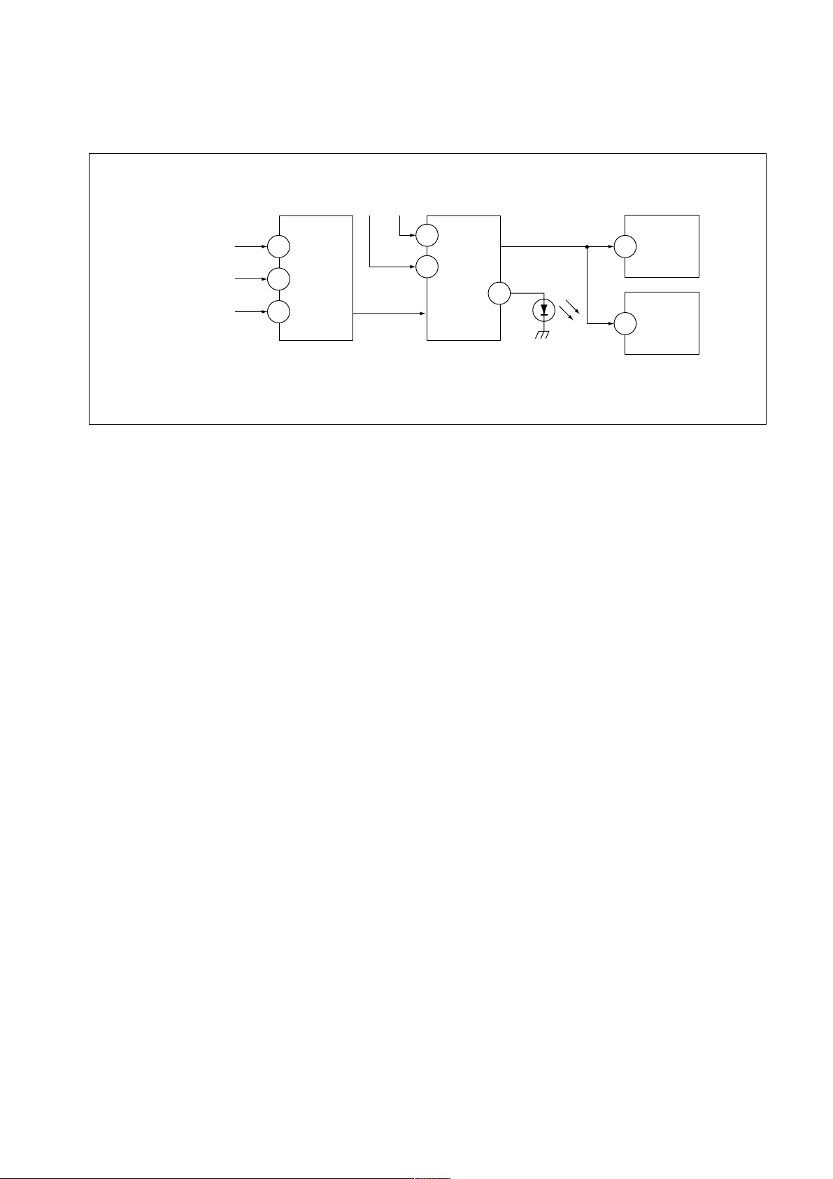
6. SELF-DIAGNOSTIC CIRCUIT
KV-ES34K90
RM-959
FROM
CRT (IK)
[H] IC6801
[V] D6806/D6801
IC4301
RGB JUNGLE
IKIN
20
XRAY
16
V PROT
CXA2100Q
OVP OCP
SDA
SYSTEM
3
6
IC001
LED
54
SDA
IC003
MEMORY
525
5
IC004
MEMORY
[+BovercurrentªOCPº] Occurs when an overcurrent on the +B(135) line is detected by Q6610
and Q6609.
If Q6610 and Q6609 go to ON, the voltage to the pin3 of IC001 go to UP.
The unit will automatically turn off.
[+BovervoltageªOVPº] Occurs when an overvoltage on the +B(135) line is detected by D6635,
Q6611 and Q6612. If Q6611 and Q6612 go to ON, the voltage to pin6 of
IC001 go to UP. The unit will automatically turn off.
[Verticaldeflectionfailure] Occurs when an absence of the vertical deflection pulse is detected by
Q6811, Q6819, Q6820, Q6821 and D6801. Shut down the power supply.
[Whitebalancefailure] If the RGB levels do not balance or become low level within 5 seconds.
This error will be detected by IC4301.
TV will stay on, but there will be no picture.
[HighvoltageprotectorofHorizontalDeflection] Occurs when an overvoltage of horizontal pulse is detected by D6809 and
IC6801.
If the voltage of 7 pin of IC6801 goes to High, the voltage to pin20 of
IC4301 go to UP. The unit will automatically turn off.
– 7 –
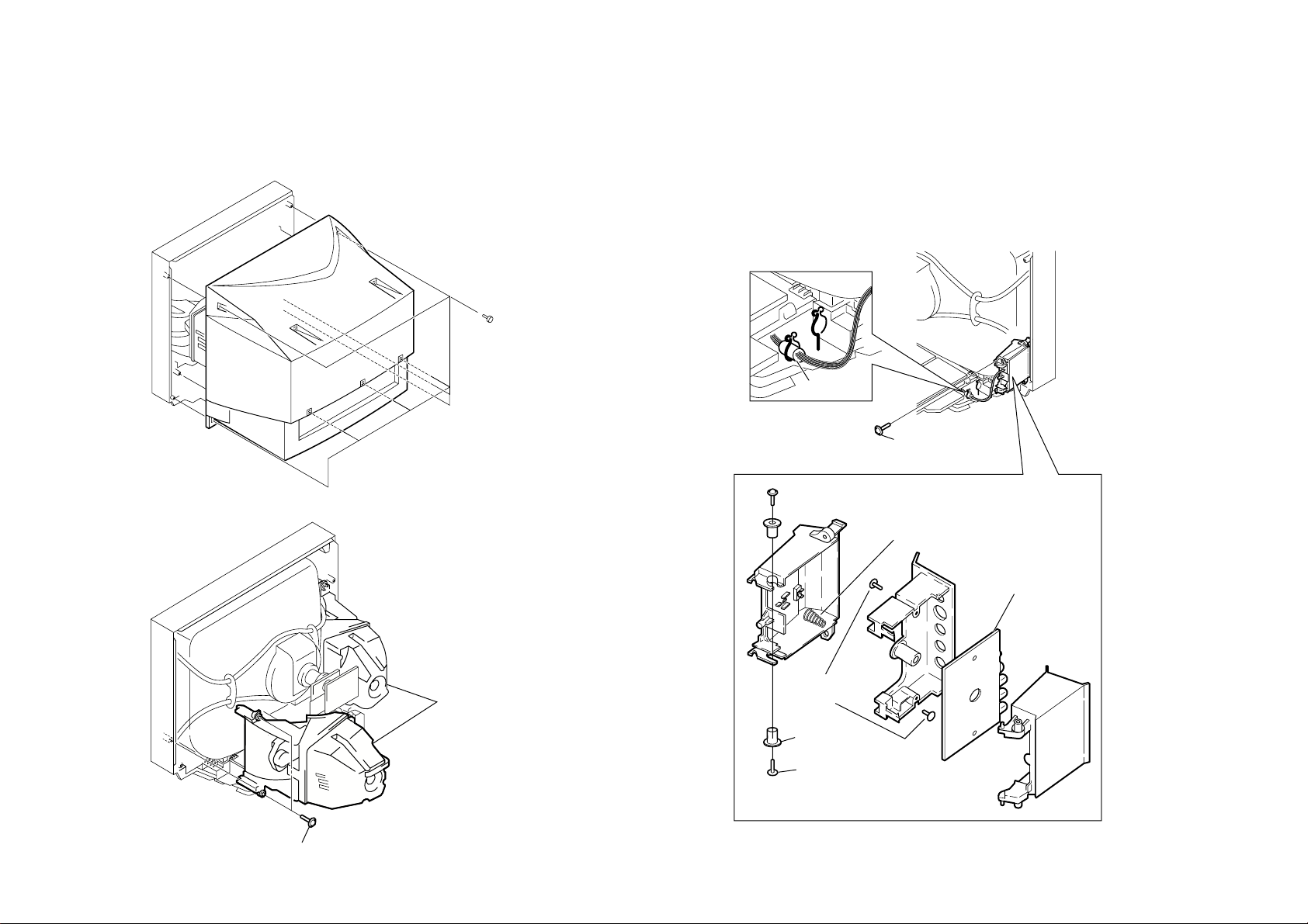
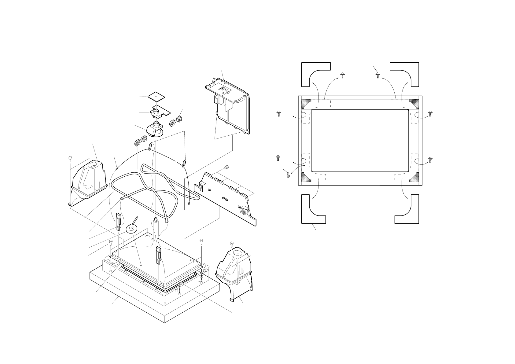
KV -ES34K90
Eight screws
(+BVTP 4X20)
1
Two screws
(TP + TWH 4X25)
2 SPEAKER BOX
L/R ASSEMBLY
1
One screw
(+BVTP 4X20)
Red tape
2
Two screws
(+BVTP 3X25)
4
Two shafts
5
Two screws
(+BVTP 3X12)
1
One spring
3
H2 Board
– 32 –
2-1. REAR COVER REMOVAL
2-2. SPEAKER BOX REMOVAL
SECTION 2
DISASSEMBLY
2-3. H2 BOARD REMOVAL
Caution: Please make sure that the red colour taped point is just placed with the
RM-959
purse lock when treating the leads to H2 board. If lead treatment is wrongly
arranged, it will affect the door opening and closing malfunction.
2-4. CHASSIS ASSY REMOVAL
Chassis
CRT Supporter
Blacket
DH board
1 Six screws
(+BVTP 3X12)
1 Two screws
(+BVTP 3X12)
1 Three screws
(+BVTP 3X12)
(+BVTP 3X12)
Four screws
3
4 J board
5 J sheild cover
Metal Case
Terminal bracket
A board
D board
2-6. DH BOARD REMOVAL
– 33 –
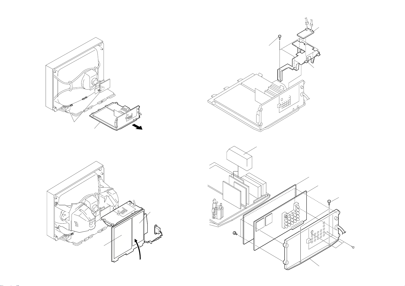
2-5. SERVICE POSITION
2-7. J BOARD REMOVAL
KV-ES34K90
RM-959
KV -ES34K90
2 Two connectors
3 Two connectors
5 V board
4 B3 board
7 D1 board
8 E board
Driver
P board
6 Metal Case
V board
1 Three screws
(+BVTP 3X12)
3
D board
2 A board
1 Three connectors
1 Four screws
(+BVTP 3X12)
Driver
H1 bracket
1
2
Driver
F2 bracket
1
2
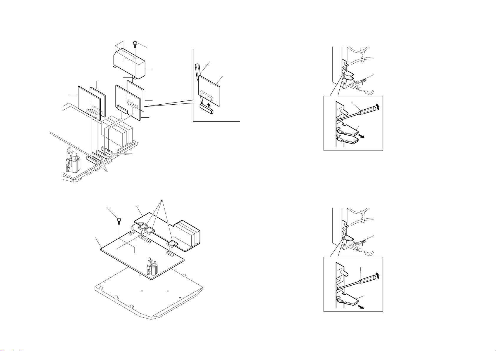
2-8. B3, D1 AND E BOARDS REMOVAL
NOTE : V Board is not used for this model.
– 34 –
2-9. A AND D BOARDS REMOVAL
2-10. H1 BOARD REMOVAL
NOTE : Push the hook down using the tip of a screwdriver and at the same time
pull the H1 bracket.
2-11. F2 BOARD REMOVAL
NOTE : To remove F2 board, firstly remove the H1 board. Then, push the hook
down using the tip of a screwdriver and at the same time pull the F2
bracket.
Caution : When removing the F2 board, please turn off the main AC supply and
disconnect the AC plug.
RM-959
– 35 –
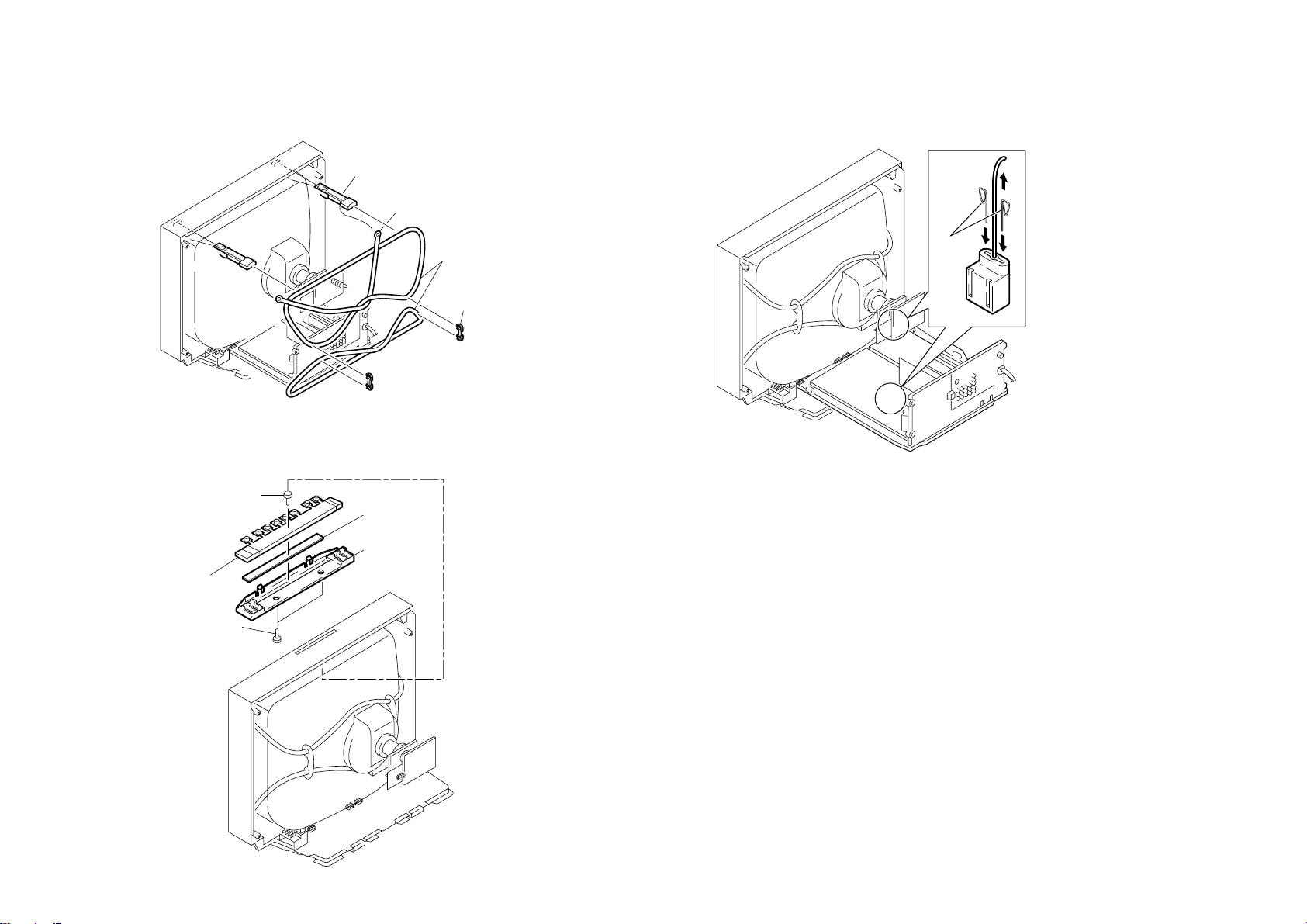
3 Two DGC clips
1 Two DGC holders
2 DGC band
4 Demagnetization
coil
1
2
Pin
4 Top switch
3 H3 board
2 H3 bracket
1 Two screws
(+BVTP 4X12)
5 One screw
(+BVTP 3X8)
2-12. DEMAGNETIZATION COIL REMOVAL
2-13. TOP SWITCH REMOVAL (H3 BOARD REMOVAL)
NOTE : To remove H3 board, the CRT has to be removed first.
2-14. G2 LEAD REMOVAL
NOTE : Insert pin to both edge holes on socket and release the lock.
KV-ES34K90
RM-959
KV -ES34K90
7 C board
5 Chassis assembly
8 Neck assembly
2 Speaker box(L)
assembly
2
Speaker box(R)
assembly
9 Deflection yoke
9 Two springs
4 Two claws
!™Two DGC
holders
!¡ Two hooks
!¢ DGC band
!£ Two DGC clips
3 Anode cap
!§ Four screws
6 Four screws
(+BVTP 4X20)
!¶ Picture tube
Cushion
1 Two screws
(TP+TWH 4X25)
1 Two screws
(TP+TWH 4X25)
!∞ Demagnetization
coil
Screw Special (Dia. 8)
Sp Screw
Fasten
× 1
× 1
× 2
× 1
Sp Screw
× 1
Sp Screw
× 1
Sp Screw
× 2
× 2
× 1
× 1 × 1
(+) TP 4 × 9
CRT Bracket
– 36 –
2-15. PICTURE TUBE REMOV AL
NOTE :i) Pr ior to picture tube removal, please remove the front cover first.
Caution : Aluminium frame is easily scratched if extra caution is not taken when
handling it.
2-16. FRAME SUB-ASSY DISASSEMBLY
1
RM-959
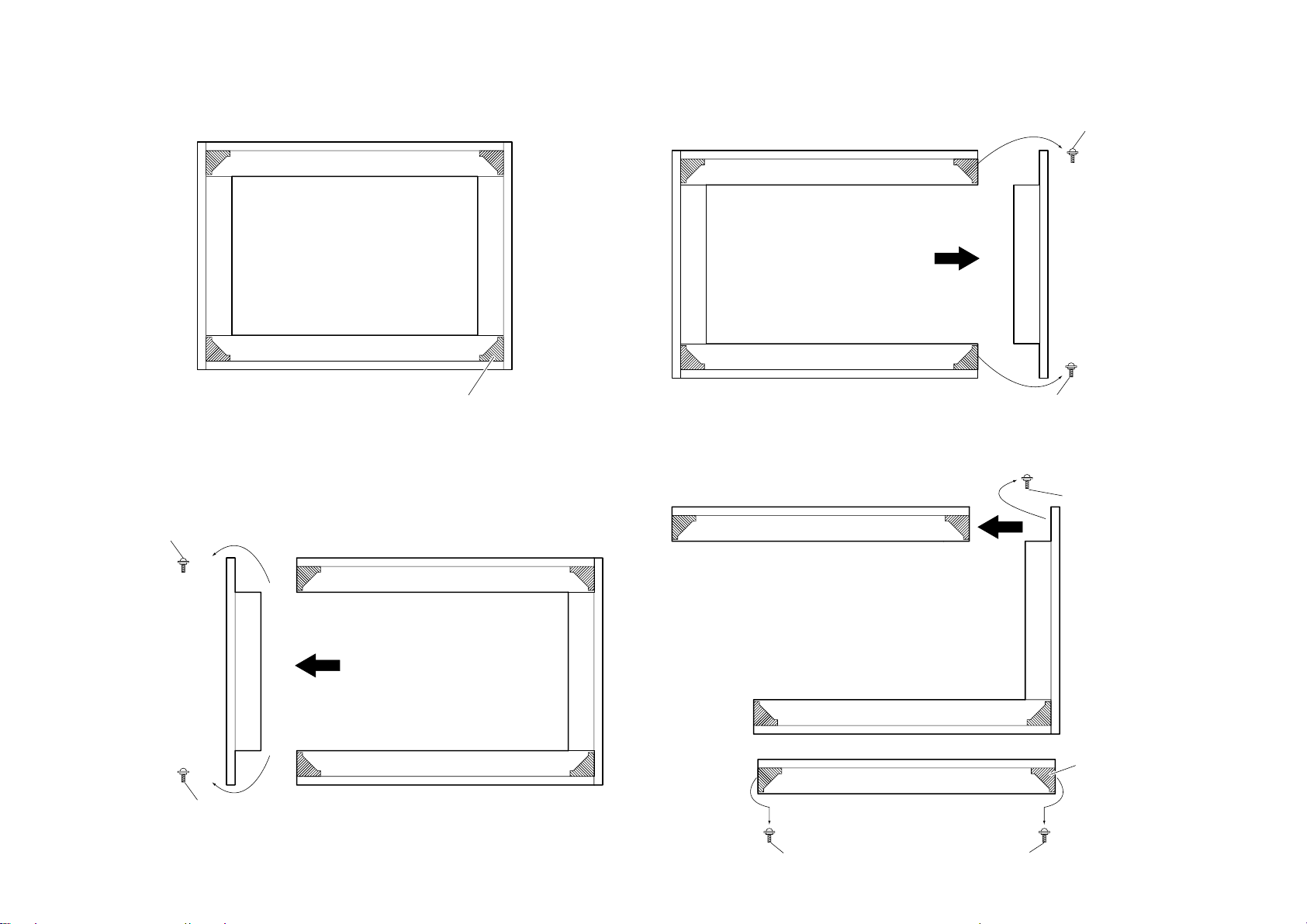
Corner Block
Slide
Screw Special (Dia. 8)
× 2
(+) TP 4 × 9
Screw Special (Dia. 8)
× 1
(+) TP 4 × 9
FRAME SUB ASSY, RIGHT REMOVAL
Slide
Screw Special (Dia. 8)
× 2
(+) TP 4 × 9
Screw Special (Dia. 8)
× 2
(+) TP 4 × 9
Slide
Screw Special (Dia. 8)
× 2
(+) TP 4 × 9
Screw Special (Dia. 8)
× 2
(+) TP 4 × 9
Screw Special (Dia. 8)
Corner Block
(+) TP 4 × 9
× 2
a)
b)
– 37 –
FRAME SUB ASSY, LEFT REMOVAL
FRAME SUB ASSY, TOP REMOVAL
KV-ES34K90
RM-959
KV -ES34K90
Slide
Screw Special (Dia. 8)
× 2
(+) TP 4 × 9
Screw Special (Dia. 8)
× 2
(+) TP 4 × 9
Screw Special (Dia. 8)
Corner Block
(+) TP 4 × 9
× 2
a)
b)
Anode button
a
a
b
b
c
– 38 –
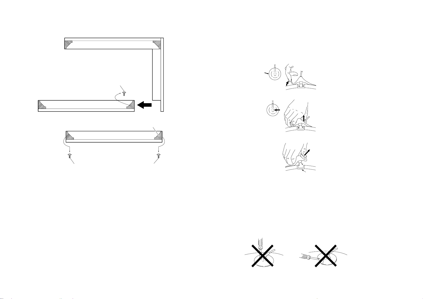
FRAME SUB ASSY, BOTTOM REMOVAL
•REMOVAL OF ANODE-CAP
NOTE : After removing the anode, short circuit the anode of the picture tube and
the anode cap to the metal chassis, CRT shield or carbon paint on the
CRT.
•REMOVING PROCEDURES
1 Turn up one side of the rubber cap in the direction indicated by the arrow a.
2 Using a thumb pull up the rubber cap firml y in the direction indicated b y the arro w b.
RM-959
NOTE : When replacing the Frame Sub-Assy Top and Bottom, fix the original cor ner
block to the new part.
3 When one side of the rubber cap is separated from the anode button, the anode-cap
can be removed by turning up the rubber cap and pulling it up in the direction of the
arrow c.
• HOW TO HANDLE AN ANODE-CAP
1 Do not damage the surface of anode-caps with sharp shaped objects.
2 Do not press the rubber too hard so as not to damage the inside of anode-cap.
A metal fitting called the shatter-hook terminal is built into the rubber.
3 Do not turn the foot of rubber over too hard.
The shatter-hook terminal will stick out or damage the rubber.
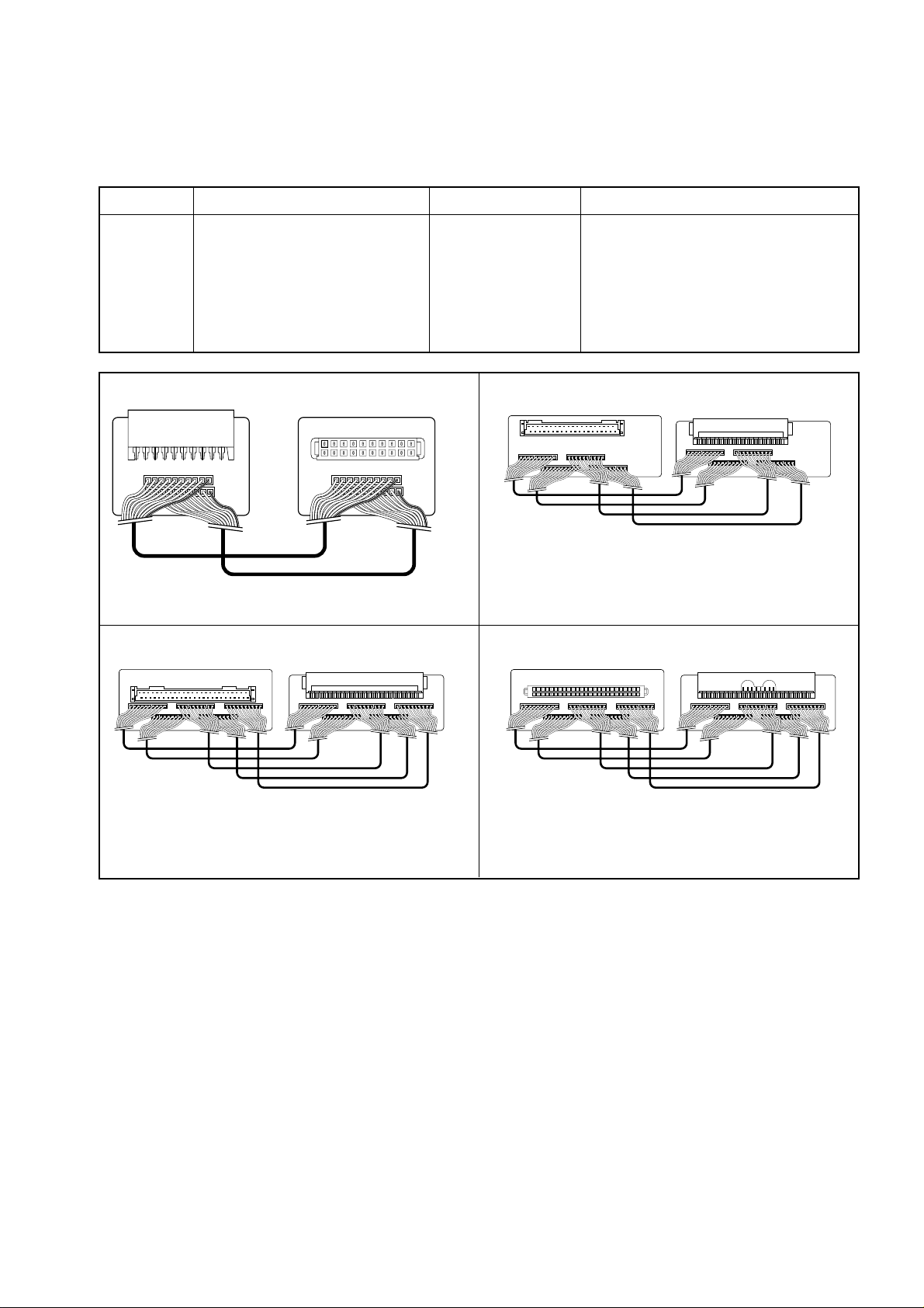
SECTION 3
SERVICE JIG
3-1. JIGS REQUIRED FOR SERVICING
REF NO. DESCRIPTION PART NO. REMARK
J-1 TOOL (20P), SERVICE 3-702-763-01 For A to V board extension
J-2 TOOL (40P), SERVICE 3-702-764-01 For A to E board extension
J-3 TOOL (50P-A), SERVICE 3-702-765-01 For A to B3 board extension
J-4 TOOL (50P-J), SERVICE 3-702-766-01 For A to J board extension
For D to D1 board extension
J-1 J-2
EX
3
EX2EX1
KV-ES34K90
RM-959
EX
4
J-3 J-4
EX
5
EX
6
EX
7
EX
8
– 39 –
KV -ES34K90
RM-959
SECTION 4
SET-UP ADJUSTMENTS
• The following adjustments should be made when a complete
realignment is required or a new picture tube is installed.
• These adjustments should be performed with rated power
supply voltage unless otherwise noted.
Controls and switches should be set as follows unless otherwise noted:
PICTURE control........................................................... normal
BRIGHTNESS control................................................... normal
................................................................................................................................................................................................................................
Preparation :
• In order to reduce the influence of geomagnetism on the set's
picture tube, face it east or west.
• Switch on the set's power and degauss with the degausser.
Perform the adjustments in the following order :
1. Beam Landing
2. Convergence
3. Focus
4. White Balance
Note : Test Equipment Required.
1. Color-bar/Pattern Generator
2. Degausser
3. Oscilloscope
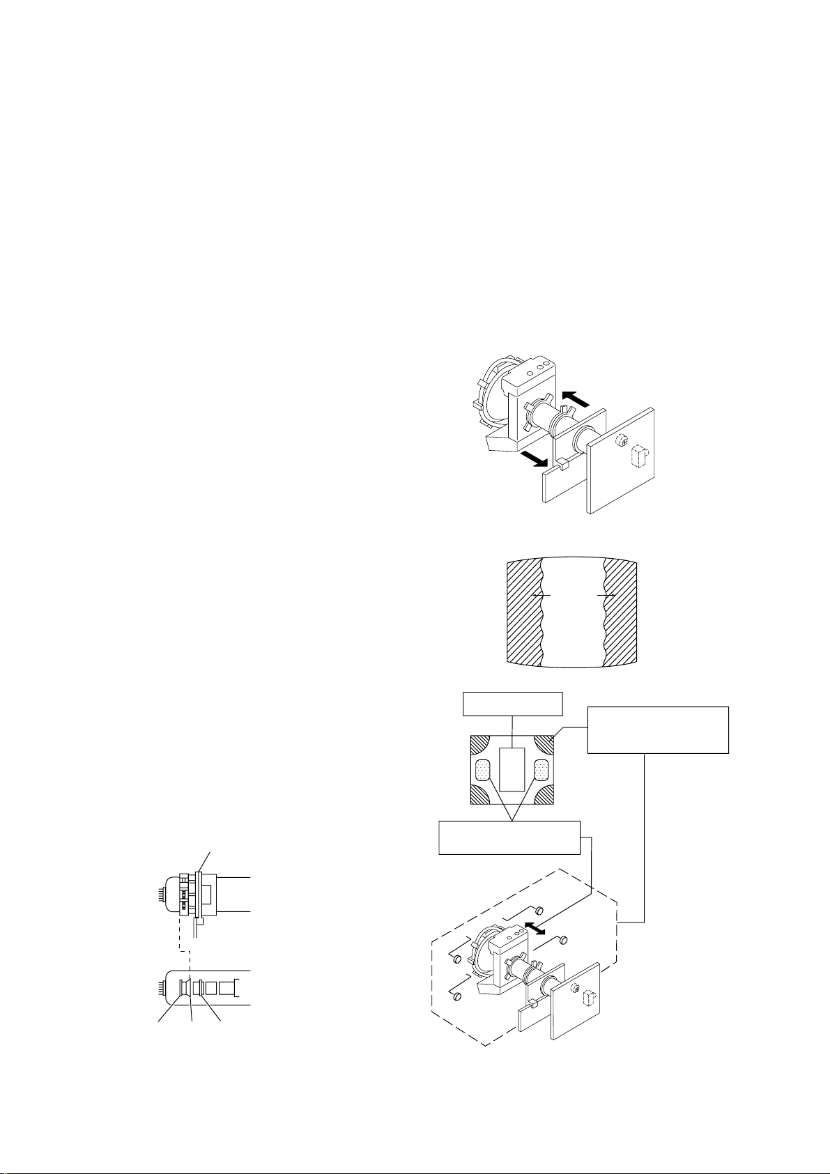
4-1. BEAM LANDING
1. Input a white signal with the pattern generator.
Contrast
Brightness
2. Position neck assy as shown in Fig4-1.
3. Set the pattern generator raster signal to a green raster.
4. Move the deflection yoke to the rear and adjust with the purity
control so that the green is at the center and the blue and the red
take up equally sized areas on each side.
(See Figures 4-1 through 4-3.)
5. Move the deflection yoke forward and adjust so that the entire
screen is green. (See Figure 4-2.)
6. Switch the raster signal to blue, then to green and verify the
condition.
7. When the position of the deflection yoke has been decided,
fasten the deflection yoke with the screws and DY spacers.
8. If the beam does not land correctly in all the corners, use a
magnet to adjust it.
(See Figure 4-4.)
}
normal
Neck assy
Fig. 4-2
Red
Green
Fig. 4-3
Purity control
corrects this area.
b
c
Deflection yoke positioning
corrects these areas.
a
d
Blue
Disk magnets or rotatable
disk magnets correct these
areas (a-d).
Behind the G2 edge
G2G1 G3
Fig. 4-1
b
c
a
d
Fig. 4-4
– 40 –
KV-ES34K90
RM-959
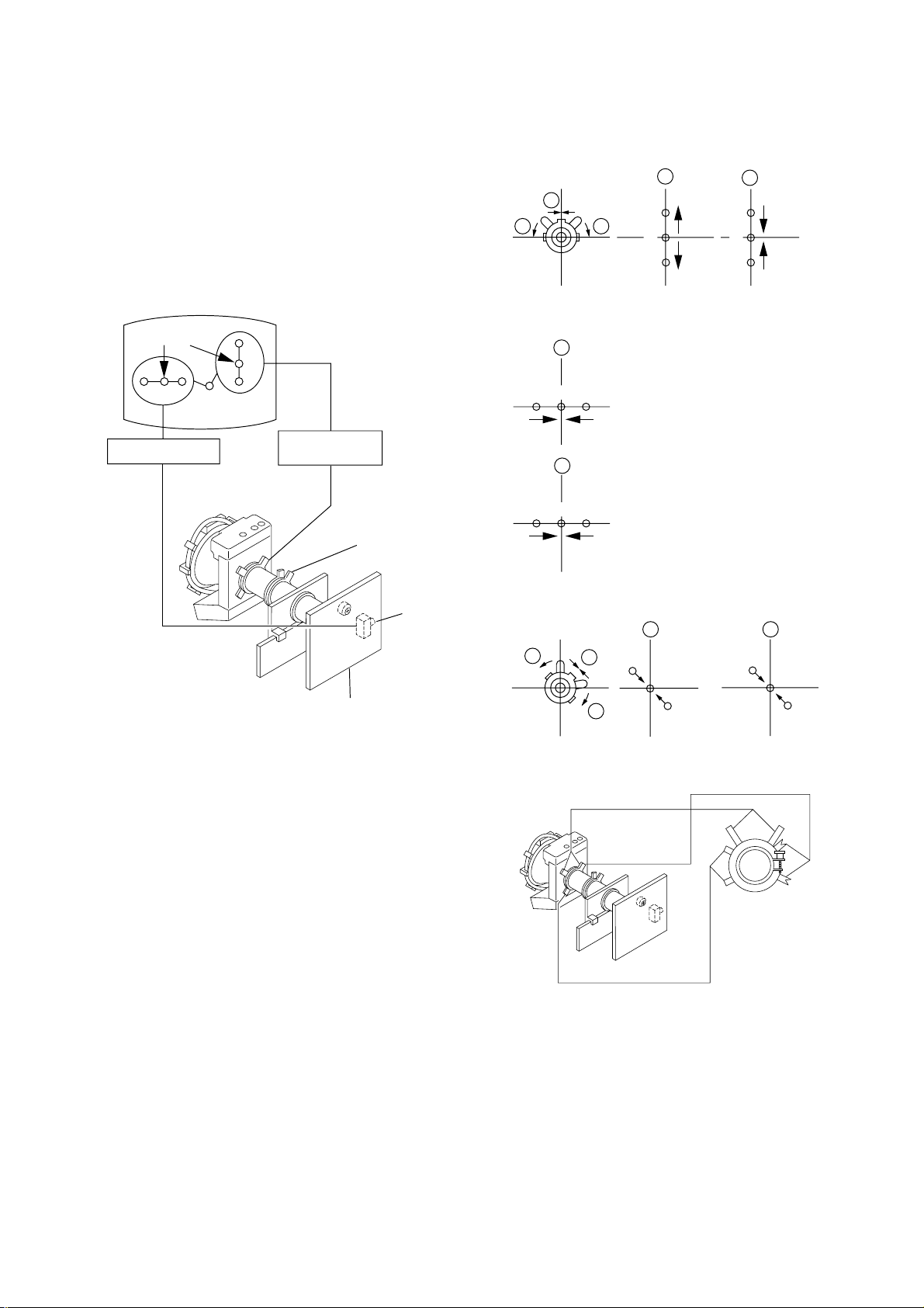
4-2. CONVERGENCE ADJUSTMENT
Preparation :
• Before starting this adjustment, adjust the focus, horizontal size
and vertical size.
• Set the Picture Mode to "STANDARD".
• Cross hatch / Dot pattern.
(1) Horizontal and Vertical Static Convergence
Center dot
R G B
H. STAT VR
R
G
B
V. STAT
Magnet
Y magnet
1 V. STAT
a
b b
2 H. STAT VR
a
RGGBB
b
a
B
G
R
R
b
B
G
R
RV702
H. STAT
C Board
1. (Moving horizontally), adjust the H.STAT control so that the
red, green and blue dots are on top of each other at the center of
the screen.
2. (Moving vertically), adjust the V.STAT magnet so that the red,
green and blue dots are on top of each other at the center of the
screen.
3. Adjust Horizontal Trapezoid with “DAC 04 HTR” in Service
Mode to make H-Trapezoid distortion best.
4. If the H.STAT variable resistor cannot bring the red, green and
blue dots together at the center of the screen, adjust the
horizontal convergence with the H.STAT variable resistor and
the V.STAT magnet in the manner given below.
(In this case, the H.STAT variable resistor and the V.STAT
magnet influence each other, so be sure to perform adjustments
while tracking.)
3
a
b
a
R
b
Purity
B
BMC (Hexapole)
V.STAT
b
B
GG
R
– 41 –
KV -ES34K90
RM-959
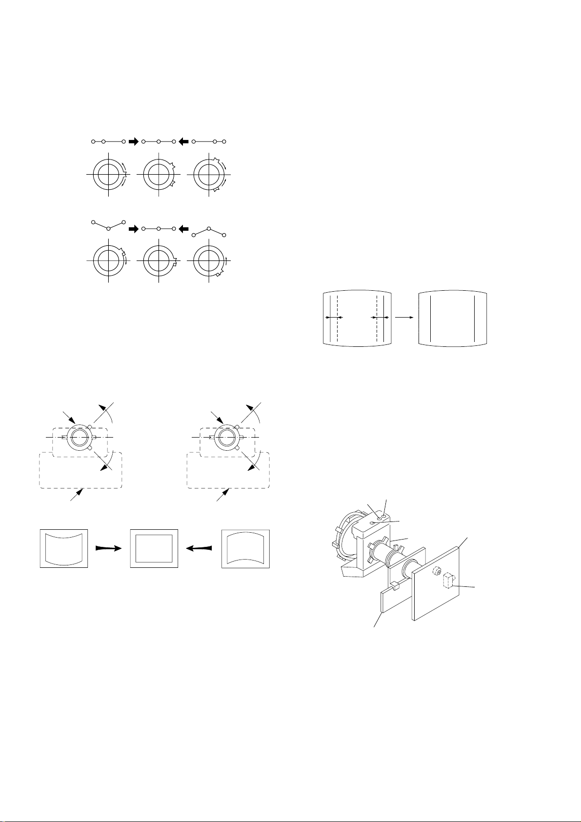
4 BMC (Hexapole) Magnet.
If the red, green and blue dots are not balanced or aligned, then
use the BMC magnet to adjust in the manner described below.
RG B R G B R GB
RB
G
RG
GB
RB
5 Y separation axis correction magnet adjustment.
1. Receive the cross-hatch signal and adjust [PICTURE] to [MIN]
and [BRIGHTNESS] to [STANDARD] .
2. Adjust the Y separation axis correction magnet on the neck
assembly so that the horizontal lines at the top and bottom of
the screen are straight.
Neck assy Neck assy
Blue
Red
Red
Blue
(2) Dynamic Convergence Adjustment
Preparation:
• Before starting this adjustment, adjust the horizontal static
convergence and the vertical static convergence
• Set the PICTURE and BRIGHTNESS to normal.
1. Adjust TLH. (TLH correction piece)
1 Receive the dot/hatch pattern signal and adjust picture quality
by the menu.
2 Correct horizontal mis-conv ergence of red and blue of both sides
on the X axis.
When red is outside insert BMC magnet to right side (THL+)
views from D Y neck. And when blue is outside, insert it to left
side (THL–) and take both sides.
R
(B)B(R)
(R)
B
TLH +
R
TLH -
(B)
2. Adjust XCV core.
To able to become balance of XCV on the X axis well.
3. Adjust V -TILT.
Correct the vertical mis-convergence of red and blue of vertically sides on the Y axis.
4. Adjust YCH.
Adjust horizontal mis-convergence of red and blue of vertically sides on the Y axis. Mentioned above steps 2 to 4 are
adjusting respectively perform minuteness tracking.
VM board
VM board
Note
1. The Red and Blue magnets should be equally far from the
horizontal center line.
2. Do not separate the Red and Blue magnets too far. (Less than
8 mm)
– 42 –
H-TRP
YCH
VM board
TLV
BMC magnet
C board
RV9001
KV-ES34K90
RM-959
(3) Screen-corner Convergence
ba
a-d : screen-corner
misconvergence
cd
Fix a Permalloy assy corresponding to the misconverged
areas.
a
b
4-3. FOCUS ADJUSTMENT
Note
Focus adjustment should be completed before W/B adjustment.
(1) Receive digital monoscope pattern.
(2) Set "A/V CONTROL" to "STANDARD".
(3) Adjust FOCUS VR so that the center of the screen becomes
justfocus.
(4) Change the receiving signal to white pattern and blue back.
(5) Confirm MAGENTA RING should not be over the limit sam-
ple. In case MAGENTA RING is over the limit sample, adjust
FOCUS VR to take tracking of MAGENTA RING and FO-
CUS.
d
Permalloy assembly
Focus
c
FLYBACK TRANSFORMER (T6803)
Screen
(No Function)
4-4. NECK ASSY TWIST ADJUSTMENT
(1) Receive dot/hatch pattern.
(2) Turn FOCUS VR fully counter-clockwise.
(3) Confirm the dot shape at the screen center. (Fig. 4-4)
(4) Resume FOCUS VR.
Note
In case of turning NECK ASSY, loosen the screw 3 turns. Do not
move the position.
OK
Turn NECK ASSY clockwise.
– 43 –
Turn NECK ASSY counter clockwise.
Fig. 4-4
KV -ES34K90
RM-959
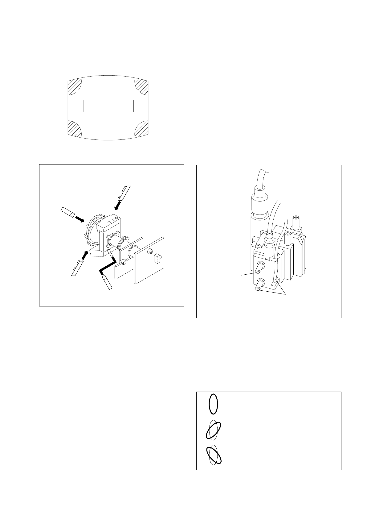
4-5. G2 (SCREEN) AND WHITE BALANCE
ADJUSTMENTS
1. G2 (SCREEN) ADJUSTMENT
1) Set the PICTURE and BRIGHTNESS to normal.
2) Put to VIDEO input mode without signals.
3) Connect R, G and B of the C board cathode to the oscilloscope.
4) Adjust BRIGHTNESS to obtain the cathode voltage to the value
below.
5) Whilst watching the picture, adjust the screen VR (RV9002)
located on the C board to the point just before the flyback return lines disappear (to the point before cut-off)
170 V ± 2 (VDC)
0 V
2. WHITE BALANCE ADJUSTMENT
1) Set to Service Mode (Refer Section 4-1: ADJUSTMENTS
WITH COMMANDER).
2) Input white raster signal.
3) Set the following condition.
PICTURE minimum, BRIGHTNESS 50%
4) Select GCT (WHB 7) and BCT (WHB 8) with
adjust the level with
5) Set the PICTURE to maximum.
6) Select GDR (WHB 4) and BDR (WHB 5) with [1] and [4], and
adjust the level with
7) Write into the memory by pressing
[3] and [6] for the best white balance.
[3] and [6] for the best white balance.
[MUTING] then [0].
[1] and [4], and
3. SUB PICTURE BRIGHTNESS ADJUSTMENT
1) Tune RF PAL white signal at program No. 1 and No. 2.
2) Select “TWIN PICTURE” mode.
3) Receive different RF PAL white signals in MAIN and Sub
picture.
4) Adjust RV3300 on A PWB, so that the output from the 17 pin
and 20 pin of the CN1180 becomes within the spec.
CVBS 1
17 pin
MAIN
A
CVBS 2
20 pin
SUB
B
Spec: |A - B| ≤ ± 20mV
– 44 –
SECTION 5
231
564
897
0
TV
DRC-MF
TV
CIRCUIT ADJUSTMENTS
5-1. ADJUSTMENTS WITH COMMANDER
Service adjustments are made with the RM-959 that comes with
this unit.
a. ENTERING SERVICE MODE
With the unit on standby
↓
[DISPLAY]
↓
5
↓
VOL (+)
↓
[POWER]
This operation sequence puts the unit into service mode.
b. METHOD OF CANCELLATION FROM SERVICE
MODE
Set the standby condition (Press [POWER] button on the commander),
then press [POWER] button again, hereupon it becomes TV mode.
KV-ES34K90
RM-959
1, 4 Select the adjustment item.
↓
3, 6 Raise/lower the data value.
↓
[MUTING] Writes.
↓
- Executes the writing.
7, - All the data becomes the values in memory.
8, - All user control goes to the standard state.
5, - Service data initialization (Be sure not to use
usually.)
[DISPLAY], - Write 50Hz adjustment data to 60Hz, or vice
versa.
2, - Copy and write all data.
c. METHOD OF WRITE INTO MEMORY
1) Set to Service Mode.
2) Press [1] (UP) and [4] (DOWN), select an item of adjustment.
3) Press [MUTING] button and it will indicate WRITE on the screen.
4) Press [0] button to write into memory.
d. MEMORY WRITE CONFIRMATION METHOD
1) After adjustment, pull out the plug from AC outlet, and then
plug into AC outlet again.
2) Turn the power switch ON and set to Service Mode.
3) Call the adjusted items again to confirm adjustments were made.
The screen display is :
Marking of virgin NVM
Data
Total Power-On time (hours)
Mode
pp
Device Name
GEO
Item Name
Item No
00
VSZ 29 SERVICE
019Q
Suffix No
(OEM Code)
Software version
1.1N 59 000AFF0
50
PAL, SECAM : 50
NTSC : 60
RM-959
– 45 –

KV -ES34K90
RM-959
5-2. ADJUSTMENT METHOD
Item Number 00 of device GEO
This explanation uses V-size as an example.
1. Select “GEO 00 VSZ” with the 1 and 4 buttons.
2. Raise/lower the data with the 3 and 6 buttons.
3. Select the optimum state. (The standard is 1F for P AL reception.)
4. Write with the
WRITE.)
5. Execute the writing with the - button. (The WRITE
display will be changed to red color while excuting, and back
to SERVICE.)
GEO 00
0 019Q
[MUTING] button. (The display changes to
29 SERVICE 50VSZ
1.1N
59 FF 0 000A
GREEN
Adjusted with [3]
and [6] buttons.
Use the same method for all Items. Use 1 and 4 to select the
adjustment item, use 3 and 6 to adjust, write with
[MUTING],
then execute the write with -.
Note : 1. In
[WRITE], the data for all items are written into memory
together.
2. For adjustment items that have different standard data
between 50Hz or 60Hz, be sure to use the respective
input signal after adjustment.
3. Additional function to skip category (de vice) to category
(device).
example:
GEO 00 VSZ
↕
DAC 00 XXX
The buttons for the function above should be cursor +/–.
GEO 00
0 019Q
GEO 00
0 019Q
1 F WRITE 50VSZ
1.1N
59 FF
Written with [MUTING]
1F SERVICE 50VSZ
1.1N
59 FF
Write executed with [0]
0 000A
0 000A
GREEN
RED
The WRITE (red display)
display returns to SERVICE
(green display)
indicates that write is executed.
– 46 –

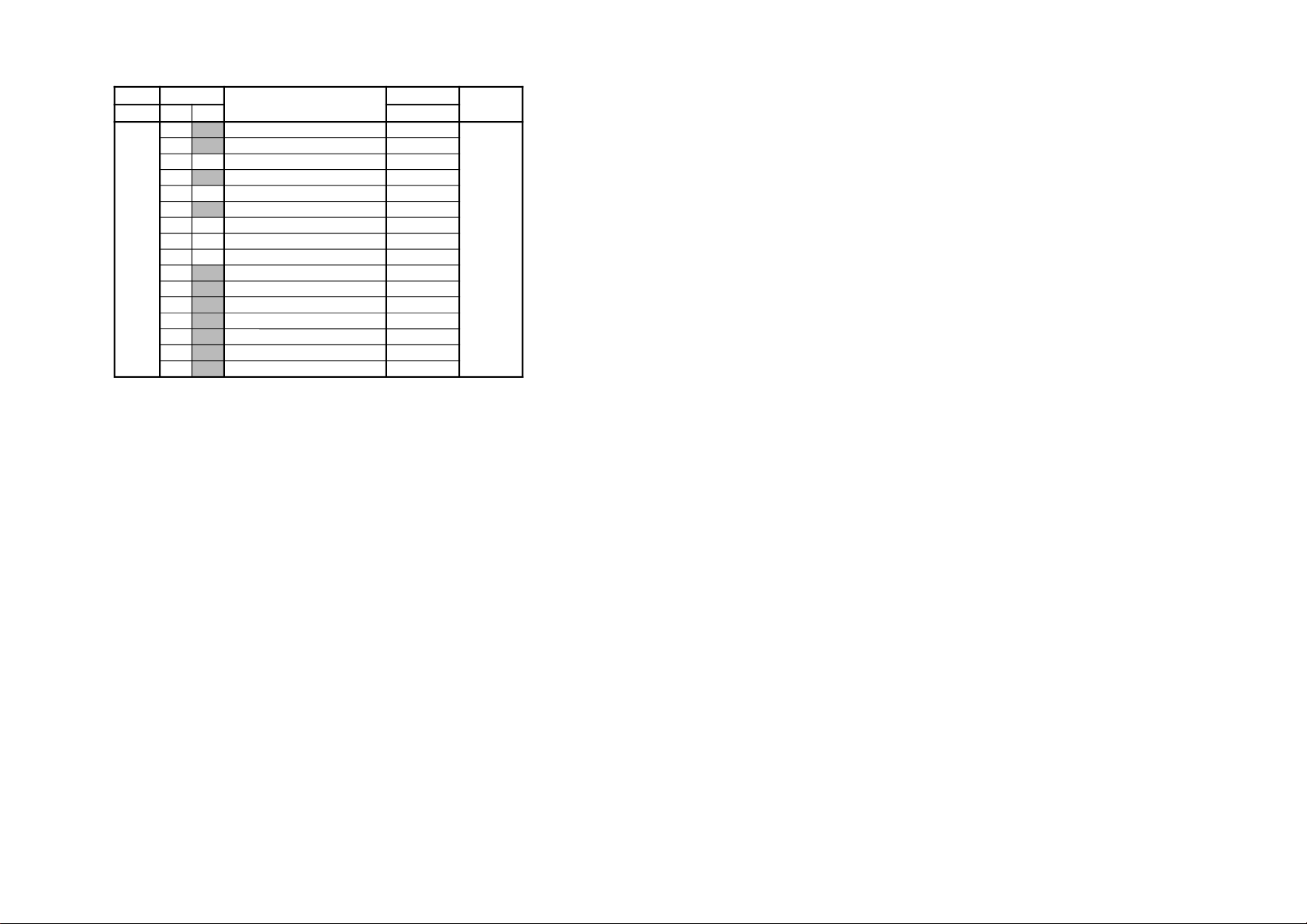
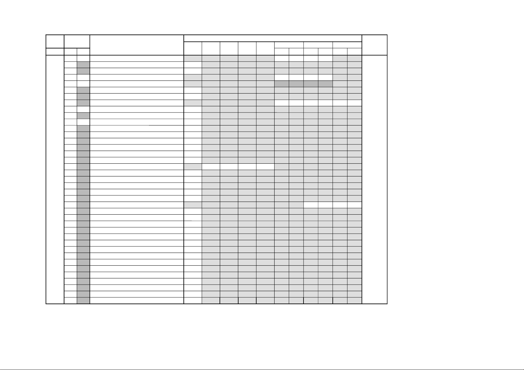
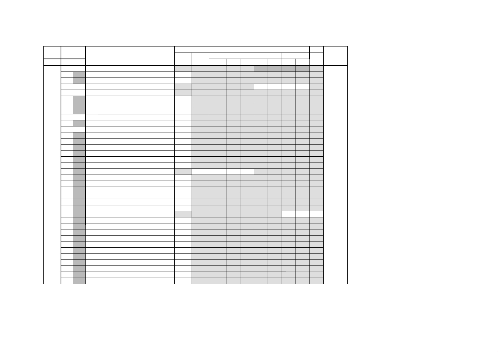
SERVICE LIST ITEM
GVTytilanoitcnuFnoitcnuF emaNeciveD
)LAP(05edoMocE)CSTN(06
yrogetaC.oNemaNCRD
0501
CRD
V0501
evissergorPVevissergorPPniPVPniPXEDNINIWTocE
nO
ocE
ffO
ocE
VnO
ocE
VffO
CRD
0501
CRD
V0501
evissergorPVevissergorPPniPVPniPXEDNINIWT
OEG00ZSVEZISVE1E1E1E1E1E1E1E1
D1D1D1D1D1D1D1D1QA0012AXC
10SPVNOITISOPV8282828282828282
9292929292929292
20NLVYTIRAENILV606060606060
607060706070
30OCSNOITCERROCSA0A0A0A0A0A0
909090909090
40ZSHEZISHF1F1F1F1F1F1F1B1
E1E1E1E1E1E1F1D1
50SPHNOITISOPHB3A3B3A3B3A3B3B3
1303130313037313
60HVDDVDROFTESFFONOITISOPH90
70
70PAPPMANIP333332333333
432343234323
80NPUNIPRENROCREPPU626262626262
62
72
52A252A252A25252
90NPLNIPRENROCREWOL321262626262
62 62
3242324232423232
A0ZRTMUIZEPARTA0A0A0A0A0A0A0A0
8090809080909060
B0LGAELGNACFA808080808080
A0A0A0A0A0A0
C0WOBWOBCFA808080808080
908080908090
D0
LBL GNIKNALBHTFEL1111111111111111
C1C1C1C1C1C1C1C1
E0
LBR GNIKNALBHTHGIRC2C2C2C2C2C2C2C2
3232323232323232
F0
NPM NOITROTSIDNIPELDDIM
NOITASNEPMOC
0000
0000
01
LVU YTIRAENILVREPPU00
00
11
LVL YTIRAENILVREWOL00
00
21
PCH EGATLOVHGIHLATNOZIROH
NOITASNEPMOC
0000
0000
31
PCV EGATLOVHGIHLACITREV
NOITASNEPMOC
0000
0000
41SAVTCEPSAV
F2F2F2F2F2F2F2F2
F203F203F2F203E2
51CSVLLORCSV
2222222222222222
2262125222521212
61
CSU FFO/NOEDOMNACS-REDNU0010
0010
71
WBV LORTNOCHTDIWGNIKNALBV003000300030
003000300030
81
1TA GNIMITECNEREFERBKA203020302030
203020302030
91YPCLLAOTATADOEGEHTYPOC
AERAMVNzH06/05
00
CAD00TCHRETNECHA4
A4
14188BM
10NLHYTIRAENILH131313131313
131313131313
20PDMNIPELDDIM020202020202
020202020202
30
PCC NIPRENROCREWOL010101010101
010101010101
40RTHMUIZEPARTLATNOZIROHF1F1F1F1F1F1
F1F1F1F1F1F1
50
FD HCTIWSFFO/NOFD101010101010
101010101010
60
HPD ESAHPFD323232323232
02F102F102F1
70
HPQ ESAHPPQ313131313131
01F001F001F0
80
CAQ EDUTILPMAPQ424242424242
424242424242
90
CDQ LEVELCDPQE1E1E1E1E1E1
E1E1E1E1E1E1
A0
VDQ NOITALUDOMVPQ828282828282
9292F2F29292
B0
VAQ NOITALUDOMEDUTILPMAPQE1E1E1E1E1E1
020232320202
C0
CBA LORTNOCA/DLBA
0000E7E7
– 47 –
KV-ES34K90
RM-959
KV -ES34K90
GVTytilanoitcnuFnoitcnuFeciveD
yrogetaC.oNemaNnommoC
BHW00
OBC 1BCROFRELLECNACTESFFOCDA0QA0012AXC
10
ORC 1RCROFRELLECNACTESFFOCDA0
20RBSLORTNOCSSENTHGIRBBUS12
30
RDR EVIRDR92
40RDGEVIRDG52
50
RDB EVIRDB02
60TCRFFOTUCR42
70TCGFFOTUCG70
80TCBFFOTUCBF2
90
OBS TESFFOSSENTHGIRBBUSC1
A0
ODR TESFFOEVIRDRF1
B0
ODG TESFFOEVIRDGB1
C0
ODB TESFFOEVIRDBB1
D0
OCR TESFFOFFOTUCRF1
E0
OCG TESFFOFFOTUCG02
F0
OCB TESFFOFFOTUCB41
SERVICE LIST ITEM
– 48 –
RM-959

SERVICE LIST ITEM
GVTytilanoitcnuFnoitcnuF emaNeciveD
nommoC0506niwTxednIedoMerutciPedoMocE
yrogetaC.oNemaN VToediVDVDVToediVDVDcimanyDdradnatSeniF-iHlanosrePCNnO-ocECNffO-ocECVnO-ocECVffO-ocE
JAS00
CIP LORTNOCERUTCIP
F32382
QA0012AXC
10
TRB LORTNOCSSENTHGIRB
32F1B1
20
LOC LORTNOCROLOC
A22222
30
EUH LORTNOCEUH
F1F1F1
40
PHS LORTNOCSSENPRAHS
22F1D1
50
LMV LEVELMV
30301030
60
CYD FFO/NOROLOCCIMANYD
10100010
70
MTC ROLOCCIMANYDROFERUTAREPMETROLOC
00000000
80XACNOITACIFICEPSXIRTAMROLOC
202020
10
10 10
90
AMG NOITCERROCAMMAG
20203020
A0
TCD LORTNOCNOISSIMSNARTCD
10100010
B0 LPD LORTNOCLEVELLATSEDEPOTUA
20100010
C0
MBA LORTNOCEDOMLBA
10000000
D0
TBA LORTNOCHTVNOITCETEDTNERRUCLBA
20002000
E0
OLC TESFFOROLOC
9080
6060
F0
WLC N/SFOEGNAHCEHTOTHTDIWPETSROLOC30
01
OUH TESFFOEUH
8080
9090
11
OHS TESFFOSSENPRAHS
4171F000F0F0
21
WHS N/SFOEGNAHCEHTOTHTDIWPETSSSENPRAHS10
31
OIP XEDNI/NIWTROFTESFFOERUTCIP
3040
41
ORB TESFFOSSENTHGIRB
70707070
LGJ00
NOP TUPTUOESLUPECNEREFERBKADNABGR
FFO/NO
10
QA0012AXC
10
BGR NOITCELESTUPTUOBGR70
20
GGA NOITCELESEDOMGNIGA00
30
SPD HCTIWSEDOMSSAPENILYALEDC/Y00
40 TBB LORTNOCRETTIMILMOTTOBBGR30
50 LML LORTNOCRETTIMILEDUTILPMABGR00
60
BAP LBAKAEPROFLEVELCDF0
70
OCS LORTNOCERUTCIPBUS70
80
2VL 2BGRROFLEVELBGR70
90
0FS 0FTIUCRICSSENPRAHS
101010101010
A0
ORP LORTNOCOITARTOOHS-REVO/ERP
003030303030
B0 ITL TNEMEVORPMITNEISNARTECNANIMUL
20200020
C0
ITC TNEMEVORPMITNEISNARTECNANIMORHC
10100010
– 49 –
KV-ES34K90
RM-959
KV -ES34K90
GVTytilanoitcnuFnoitcnuF emaNeciveD
nommoCD2
bmoC
D3
bmoC
tupnI-SsrehtOVToediVDVD
yrogetaC.oNemaN 050605060506
TCY00TNTCSTNROFTNEMTSUJDATNIT
4242F1F1
Q3212AXC
10
GNP HTDIWETAGCSTN/LAP10
20
INP WSYTIVITISNESCSTN/LAP00
30LCSLORTNOCROLOCBUS
50708060
40TCSLORTNOCTSARTNOCBUS
80 50 80
70
50
0FS GNIGNAHCYCNEUQERFRETNECSSENPRAHS20
60
QES CITSIRETCARAHCREZILAUQESSENPRAHS30
70
GHS LORTNOCNIAGSSENPRAHS
506050607070
80LOYLORTNOCLEVELTUPTUO-YF1
90
PSB GNIGNAHCTNIOPTRATSHCTERTSKCALB00
A0LOCLORTNOCLEVELTUPTUORC/BCA1
B0 RCD TNEMTSUJDAOITARNOITAROTSERCD00
C0
0FB TNEMTSUJDA0FFQT/FPB10
D0
QFB TNEMTSUJDAQFQT/FPB20
E0
WSF HCTIWSFQT/FPB10
F0 TDS HCTIWSPARTELBUODMACES10
01
FPL HCTIWSFPLRC/BC/Y10
11
LDY TNEMTSUJDAEMITLD-Y
60503050
21 TMC HCTIWSETUMTUPTUORC/BC00
31
1OB )ETUORNIAM(TNEMTSUJDA1TESFFOBC70
41
1OR TNEMTSUJDA1TESFFORC70
51
FDC HCTIWSYCNEUQERFNWODTNUOCV00
61
MDC HCTIWSEGDUJNWODTNUOCV00
71
CFA HCTIWSYTIVITISNESCFA
00000000
81
MVM KSAMCFA+KSAMNOISIVORCAM00
91
YRS TNEMTSUJDAKCALBY-RMACES70
A1
YBS TNEMTSUJDAKCALBY-BMACES10
B1
LEB GNIHCTIWSFPH/LLEBMACES20
C1
FLB TNEMTSUJDA0FLLEB00
D1
IVS HCTIWSDI-VMACES00
E1
PGS TNEMTSUJDANOITISOPETAGMACES00
F1
DIS HCTIWSYTIVITISNESMACES10
02
HIS HCTIWSNOITIBIHNIMACES00
12
PTS SULPLAPROFPUTESLEVELKCALBY00
22
CVH GNILLECNACRETCARAHCERUTAREPMETOCV-H20
32
RN3 FFO/NONOITAREPORND310
42
6WB FFO/NOLANGISTSUB-NONzH06ROFRND310
52 HSW NOITCUDERESIONROFPETSNIAGSSENPRAHS00
62
OCW TNEMTSUJDAOITARNOITAROTSERCD00
SERVICE LIST ITEM
– 50 –
RM-959
SERVICE LIST ITEM
GVTytilanoitcnuFnoitcnuF emaNeciveD
nommoCtupnI-SedoMloCVToediVDVD
yrogetaC.oNemaN MACESCSTNLAP05060506
CYS00TNTCSTNROFTNEMTSUJDATNIT
12 12 02
02
Q3212AXC
10
GNP HTDIWETAGCSTN/LAP10
20
INP WSYTIVITISNESCSTN/LAP00
30LCSLORTNOCROLOCBUS
60709060
40TCSLORTNOCTSARTNOCBUS
80
40
80 70
50
0FS GNIGNAHCYCNEUQERFRETNECSSENPRAHS20
60
QES CITSIRETCARAHCREZILAUQESSENPRAHS30
70
GHS LORTNOCNIAGSSENPRAHS70
80LOYLORTNOCLEVELTUPTUO-YF1
90
PSB GNIGNAHCTNIOPTRATSHCTERTSKCALB00
A0LOCLORTNOCLEVELTUPTUORC/BCC3
B0 RCD TNEMTSUJDAOITARNOITAROTSERCD00
C0 0FB TNEMTSUJDA0FFQT/FPB10
D0
QFB TNEMTSUJDAQFQT/FPB20
E0
WSF HCTIWSFQT/FPB10
F0 TDS HCTIWSPARTELBUODMACES10
01
FPL HCTIWSFPLRC/BC/Y10
11
LDY TNEMTSUJDAEMITLD-Y
50302030
21
MCN HCTIWSNOITIDDAH-110
31 TMC HCTIWSETUMTUPTUORC/BC00
41 1OB )ETUORNIAM(TNEMTSUJDA1TESFFOBC70
51 1OR TNEMTSUJDA1TESFFORC70
61
FDC HCTIWSYCNEUQERFNWODTNUOCV00
71
MDC HCTIWSEGDUJNWODTNUOCV00
81
CFA HCTIWSYTIVITISNESCFA
000000
91
MVM KSAMCFA+KSAMNOISIVORCAM00
A1 YRS TNEMTSUJDAKCALBY-RMACES70
B1
YBS TNEMTSUJDAKCALBY-BMACES10
C1
LEB GNIHCTIWSFPH/LLEBMACES20
D1
FLB TNEMTSUJDA0FLLEB00
E1
IVS HCTIWSDI-VMACES00
F1
PGS TNEMTSUJDANOITISOPETAGMACES00
02
DIS HCTIWSYTIVITISNESMACES10
12
HIS HCTIWSNOITIBIHNIMACES00
22
PTS SULPLAPROFPUTESLEVELKCALBY00
32
CVH GNILLECNACRETCARAHCERUTAREPMETOCV-H20
– 51 –
KV-ES34K90
RM-959
KV -ES34K90
GVTytilanoitcnuFnoitcnuFeciveD
yrogetaC.oNemaN nommoC
PSM00
TSW DLOHSERHTOERETSG/W51D5143PSM
10 TBW DLOHSERHTLAUGNILIBG/WAE
20
LLW DLOHSERHTLARUAONOMG/W50
30
CAW TNUOCTNEMEERGAG/W10
40
LDW YALEDHCRAESG/W03
50
LDN YALEDHCRAESMACIN02
60
LDS YALEDDAERSUTATSOERETS01
70 CGA TNATSNOC/OTUAHCTIWSCGA10
80
LER EDOMTNATSNOCTANIAGCGA82
90
MRC FFO/NOGNITUMREIRRAC00
A0
OCA FFO/NOKCOLCOIDUA10
B0
PF METSYSM-NONROFELACSERPMFB1
C0
MPF METSYSMROFELACSERPMF23
D0
HF VEDHROFELACSERPMFD2
E0
MHF MDNAVEDHROFELACSERPMF56
F0
PGW ELACSERPG/WA2
01
PIN ELACSERPMACIND6
11
RRE DLOHSERHTHCTIWSMFOTUA05
21 LOV HFF70OTH0070NIAGREKAEPSDUOLD6
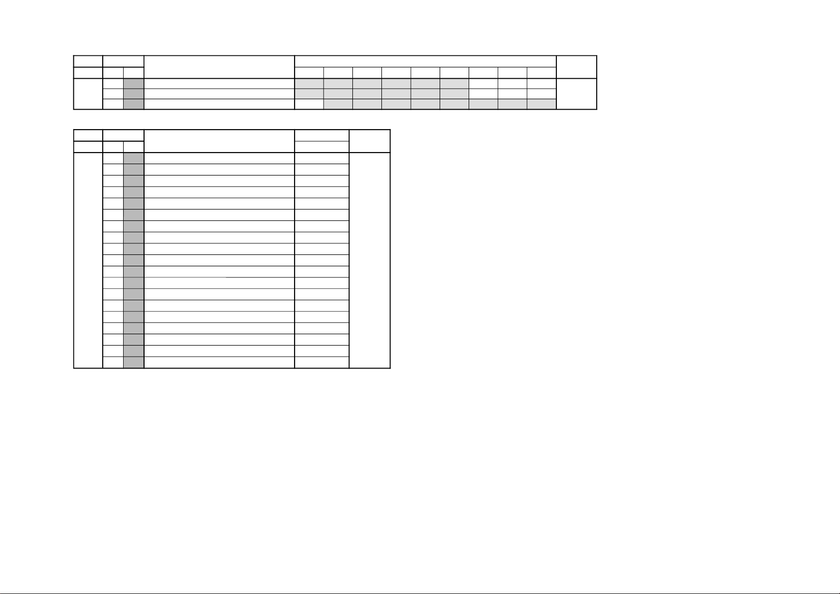
GVTytilanoitcnuFnoitcnuF emaNeciveD
yrogetaC.oNemaN nommoCDDVruSPDVruSSRTruSMISruSffOruScimanyDamarDtfoS
PA00
SABLORTNOCSSAB
B080705137ADT
10
ERTLORTNOCELBERT
B09070
20
NDLFFO/NOSSENDUOL10
SERVICE LIST ITEM
– 52 –
RM-959
SERVICE LIST ITEM
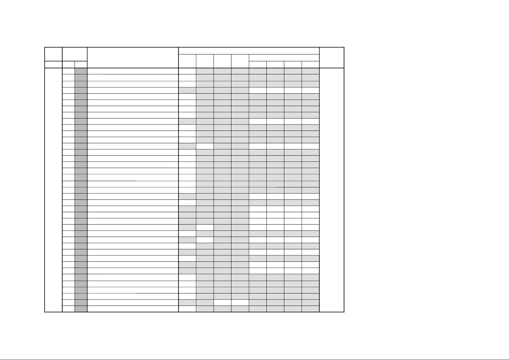
GVTytilanoitcnuFnoitcnuF emaNeciveD
nommoCniwTVToediVedoMerutciP
yrogetaC.oNemaN cimanyDdradnatSeniF-iHlanosreP
ITL00
HDL NOITCELESTNEMGESMARGOTSIH10
8719ADT
10
SFC NOITCELESRETLIFRUOTNOC10
20
BLW HCTIWSWODNIWXOBRETTEL00
30
CDV GNIROCTNEDNEPEDOEDIV
10101010
40
MED EDOMNOITARTSNOMED00
50
PDC YALEDECNANIMUL40
60
PSO GNIKAEPTRAMSELURREVO00
70 OPW FFOHCTERTSTNIOPETIHW00
80
KSD HCTIWSENOTNIKS
00000000
90
KSA NOITCELESELGNAENOTNIKS00
A0 KSW NOITCELESHTDIWENOTNIKS00
B0
KSS NOITCELESEZISENOTNIKS00
C0 RGD HCTIWSTNEMECNAHNENEERG
00
10100010
D0
TGD HCTIWSTNEMECNAHNENEERGFODLOHSERHT70
E0
RGG NIAGTNEMECNAHNENEERG00
F0 RGW HDTIWTNEMECNAHNENEERG00
01
RGS EZISTNEMECNAHNENEERG00
11
LBD HCTIWSHCTERTSEULB00
21
LBG NOITCELESNIAGHCTERTSEULB00
31
LBS NOITCELESEZISHCTERTSEULB00
41
SDC SSENPRAHSTNEDNEPEDROLOC
10100010
51
TSC SSENPRAHSTNEDNEPEDROLOCFODLOHSERHT70
61
ITC TNEMEVORPMITNEISNARTROLOC
00000000
71
NOB NOITASNEPMOCTESFFOKCALB
00000000
81
DTB HCTERTSKCALBEVITPADA
00000000
91
DLN REIFILPMAYTIRAENIL-NON
00
51510051
A1
WLN REIFILPMAYTIRAENIL-NONFOHTDIWPETS70
B1 DGV AMMAGELBAIRAV
F1
F1F1F1F1
C1
WGV AMMAGELBAIRAVFOHDTIWPETS00
D1
DKP EDUTILPMAGNIKAEP
F303E003
E1
WKP EDUTILPMAGNIKAEPFOHTDIWPETS80
F1
DPS NOITCERROCSSENPETS
00000000
02
DRC LEVELGNIROC
61610061
12
WRC LEVELGNIROCFOHTDIWPETS90
22
ORC EDOMOEDIVROFTESFFOLEVELGNIROC10
32
DWL NOITCERROCHTDIWENILF1
42
MNS NOITIDNOCN/SELBILAERNUREDNUEDOMN/S00
52
CNS RETNUOCEGAREVAOITARN/S
3030
62
CMF RETNUOCGNIHCTAMEDOMERUTAEF20
– 53 –
KV-ES34K90
RM-959
KV -ES34K90
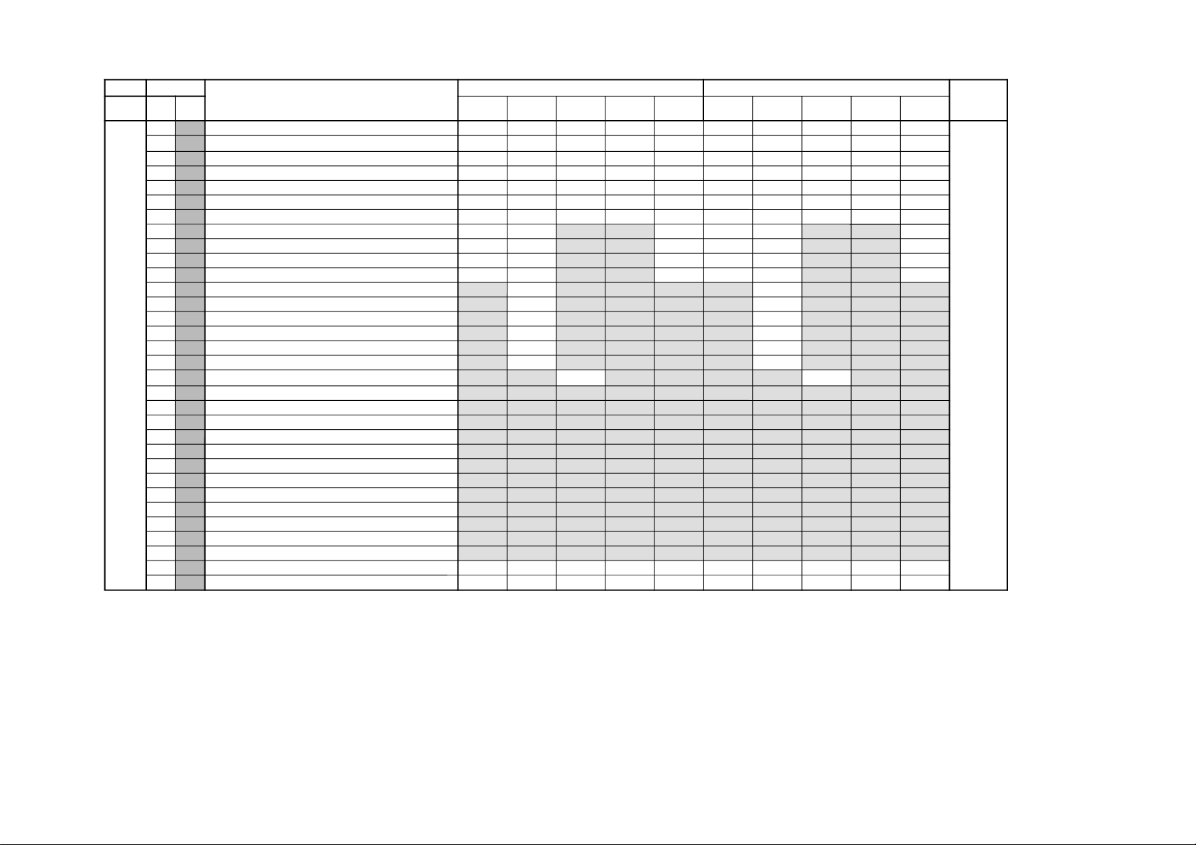
GVTytilanoitcnuFnoitcnuF05
06
emaNeciveD
yrogetaC.oNemaN 0501CRDPniPNIWTXEDNI-vissergorP
e
0501CRDPniPNIWTXEDNI-vissergorP
e
DIM00
HPH ESAHPAERAYALPSIDEVITCALATNOZIROH 252529D8252525F7F72581949BM
10
HPV ESAHPAERAYALPSIDEVITCALACITREV 0202420202525252E252
20 ZSH EZISAERAYALPSIDEVITCALATNOZIROH F7F7F7F7F7F7F7F7F7F7
30 ZSV EZISAERAYALPSIDEVITCALACITREV F7F7F7F7F7F7F7F7F7F7
40
WPH HTDIWSULPCNYS-HYALPSID F3F3F3F3F3F3F3F3F3F3
50
WPV HTDIWSULPCNYS-VYALPSID 10703030701070303070
60
LDY NOITCERROCYALEDC/YTUPTUOYALPSID 00000000000000000000
70
PHM )PNIP&ELGNIS(NOITISOPLATNOZIROHERUTCIPNIAM F7F7
F7F7F7
F7
80
PVM )PNIP&ELGNIS(NOITISOPLACITREVERUTCIPNIAM F7F7
F7F7F7
F7
90
SHM )PNIP&ELGNIS(EZISLATNOZIROHERUTCIPNIAM F7F7
F7F7F7
F7
A0
SVM )PNIP&ELGNIS(EZISLACITREVERUTCIPNIAM F7F7
F7F7F7
F7
B0
PHP NOITISOPLATNOZIROHERUTCIPBUSPNIP
B6
35
C0 PVP NOITISOPLACITREVERUTCIPBUSPNIP
D5
75
D0
SHP EZISLATNOZIROHERUTCIPBUSPNIP
F7
F7
E0
SVP EZISLACITREVERUTCIPBUSPNIP
F7
F7
F0
OHP TESFFONOITISOPLATNOZIROHERUTCIPBUSPNIP
67
86
01
OVP TESFFONOITISOPLACITREVERUTCIPBUSPNIP
96
46
11
PMT NOITISOPLATNOZIROHERUTCIPNIAMNIWT
00
00
21
PST NOITISOPLATNOZIROHERUTCIPBUSNIWT
31
PVT NOITISOPLACITREVERUTCIPBUS&NIAMNIWT
41
SHT EZISLATNOZIROHERUTCIPBUS&NIAMNIWT
51
SVT EZISLACITREVERUTCIPBUS&NIAMNIWT
61
OHT TESFFONOITISOPLATNOZIROHERUTCIPBUS&NIAMNIWT
71
OVT TESFFONOITISOPLACITREVERUTCIPBUS&NIAMNIWT
81
SHX EZISLATNOZIROHERUTCIPBUSXEDNI
91
SVX EZISLACITREVERUTCIPBUSXEDNI
A1
GHX SERUTCIPNEEWTEBHTDIWPAGLATNOZIROHXEDNI
B1
GVX SERUTCIPNEEWTEBHTDIWPAGLACITREVXEDNI
C1 PHX NOITISOPLATNOZIROHSERUTCIPBUSTS1XEDNI
D1 PVX NOITISOPLACITREVSERUTCIPBUSTS1XEDNI
E1 PHD NOITISOPAERAEVITCALATNOZIROHCRD F7F7F7F7F7F7F7F7F7F7
F1
SHD EZISLEXIPEVITCALATNOZIROHCRD F7F7F7F7F7F7F7F7F7F7
SERVICE LIST ITEM
– 54 –
RM-959
 Loading...