

Page 1
TA-S3
SERVICE MANUAL
Ver 1.0 2001.05
TA-S3 is the Amplifier section in
MHC-S3.
SPECIFICATIONS
Amplifier section
DIN power output (rated) 60 + 60 watts
Continuous RMS power output (reference)
Music power output (reference)
Inputs
VIDEO (AUDIO) IN: voltage 250 mV,
(phono jacks) impedance 47 kilohms
MD IN: voltage 450 mV,
(phono jacks) impedance 47 kilohms
OPTICAL IN:
(Square optical connector jacks, rear panel)
wavelength 700 nm
Outputs
MD OUT: voltage 250 mV
(phono jacks) impedance 1 kilohms
PHONES: accepts headphones of
(stereo mini jack) 8 ohms or more
FRONT SPEAKER: accepts impedance of 6 to
SUB WOOFER OUT: Voltage 1 V,
(6 ohms at 1 kHz, DIN)
80 + 80 watts
(6 ohms at 1 kHz, 10%
THD)
150 + 150 watts
(6 ohms at 1 kHz, 10%
THD)
16 ohms
impedance 1 kilohms
General
Power requirements 230 V AC, 50/60 Hz
Power consumption 180 watts
Dimensions (w/h/d)
Mass Approx. 6.2 kg
Design and specifications are subject to change
without notice.
0.6 watts (during Power
Saving Mode)
Approx. 280 x 128 x 350 mm
AEP Model
UK Model
9-873-874-11 Sony Corporation
2001E0500-1 Home Audio Company
C 2001.5 Shinagawa Tec Service Manual Production Group
AV AMPLIFIER
Page 2

TA-S3
TABLE OF CONTENTS
1. SERVICING NOTES............................................... 3
2. GENERAL ................................................................... 4
3. DISASSEMBLY
3-1. Disassembly Flow ........................................................... 5
3-2. Cover ............................................................................... 6
3-3. Front Panel Section ......................................................... 6
3-4. Back Panel (2CH/VCD) Section .................................... 7
3-5. FRONT AMP Board ....................................................... 7
4. TEST MODE.............................................................. 8
5. DIAGRAMS
5-1. Note for Printed Wiring Boards
and Schematic Diagrams ................................................ 10
5-2. Printed Wiring Boards – FRONT AMP Section – ........ 11
5-3. Schematic Diagram – FRONT AMP Section (1/2) – .... 12
5-4. Schematic Diagram – FRONT AMP Section (2/2) – .... 13
5-5. Printed Wiring Boards – CONTROL Section – ............ 14
5-6. Schematic Diagram – CONTROL Section –................. 15
5-7. Printed Wiring Boards – POWER Section – ................. 16
5-8. Schematic Diagram – POWER Section – ..................... 17
5-9. IC Pin Function Description ........................................... 18
6. EXPLODED VIEWS
6-1. Cover Section .................................................................. 18
6-2. Front Panel Section ......................................................... 19
6-3. Chassis Section ............................................................... 20
7. ELECTRICAL PARTS LIST ............................... 21
SAFETY-RELATED COMPONENT WARNING!!
COMPONENTS IDENTIFIED BY MARK 0 OR DOTTED
LINE WITH MARK 0 ON THE SCHEMATIC DIAGRAMS
AND IN THE PARTS LIST ARE CRITICAL TO SAFE
OPERATION. REPLACE THESE COMPONENTS WITH
SONY PARTS WHOSE PART NUMBERS APPEAR AS
SHOWN IN THIS MANU AL OR IN SUPPLEMENTS PUBLISHED BY SONY.
2
Page 3
SECTION 1
SERVICING NOTES
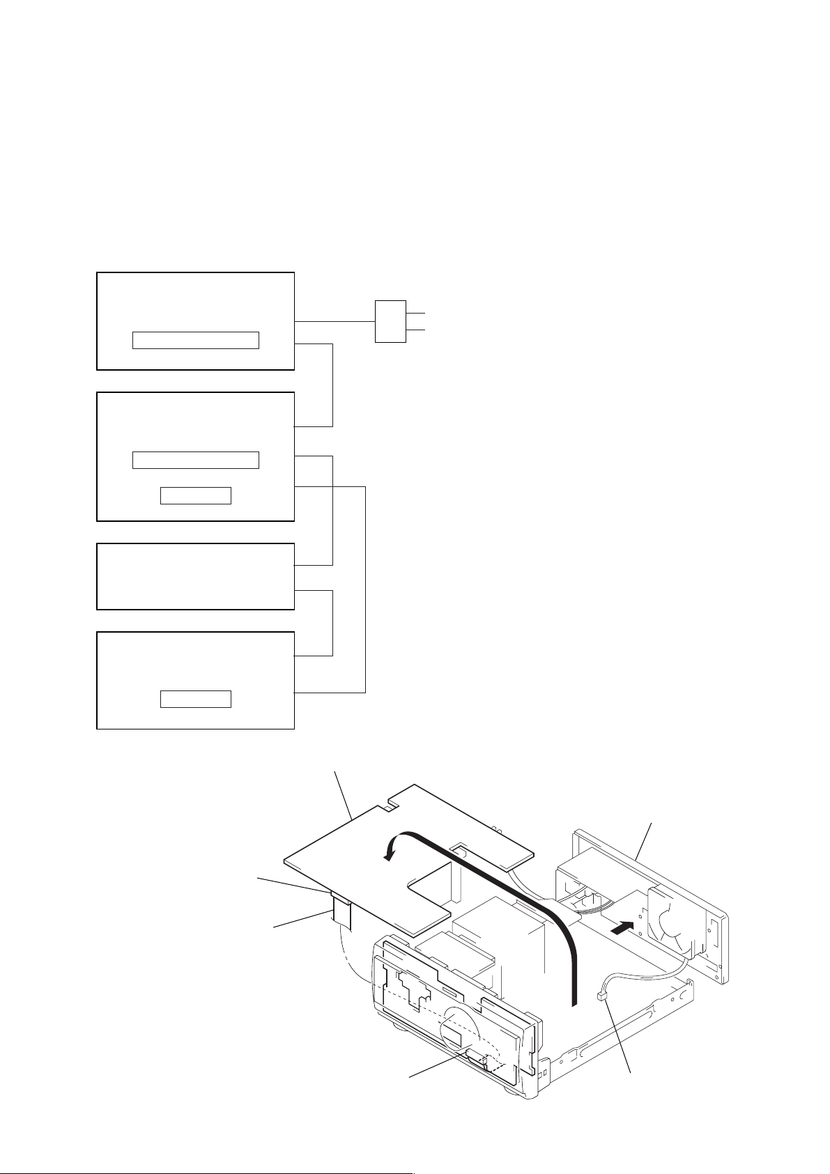
This set is a component of the MHC-S3.
The MHC-S3 system configuration is as shown below, and therefore it does not operate normally unless all four components are
connected.
In performing the repair, connect all components with the system
cables.
Note: The precaution to the users is described on the label stuck on the
back panel (CD player) and in the troubleshooting section in the
Operation Manual.
System Configuration:
AC IN
TA
POWER SUPPLY
ST
TA-S3
SYSTEM & CD µcon
DISPLAY
CDP
TC
TC µcon
FRONT AMP BOARD SERVICE POSITION
In checking the FRONT AMP board, prepare jig
(extension cable J-2501-087-A: 1.25 mm Pitch, 23 core, Length
300 mm)
(Fig A)
Turn over the FRONT AMP board with Heat Sink, THP board
and RELAY board connected.
Remove the back panel
(2CD/VCD) section.
FRONT AMP board
(CN104)
Connect jig (extension
cable J-2501-087-A
to the FRONT AMP board (CN104)
and PANEL board (CN700).
PANEL board (CN700)
Remove the fan motor
connector lead wire.
(Fig A)
3
Page 4
TA-S3
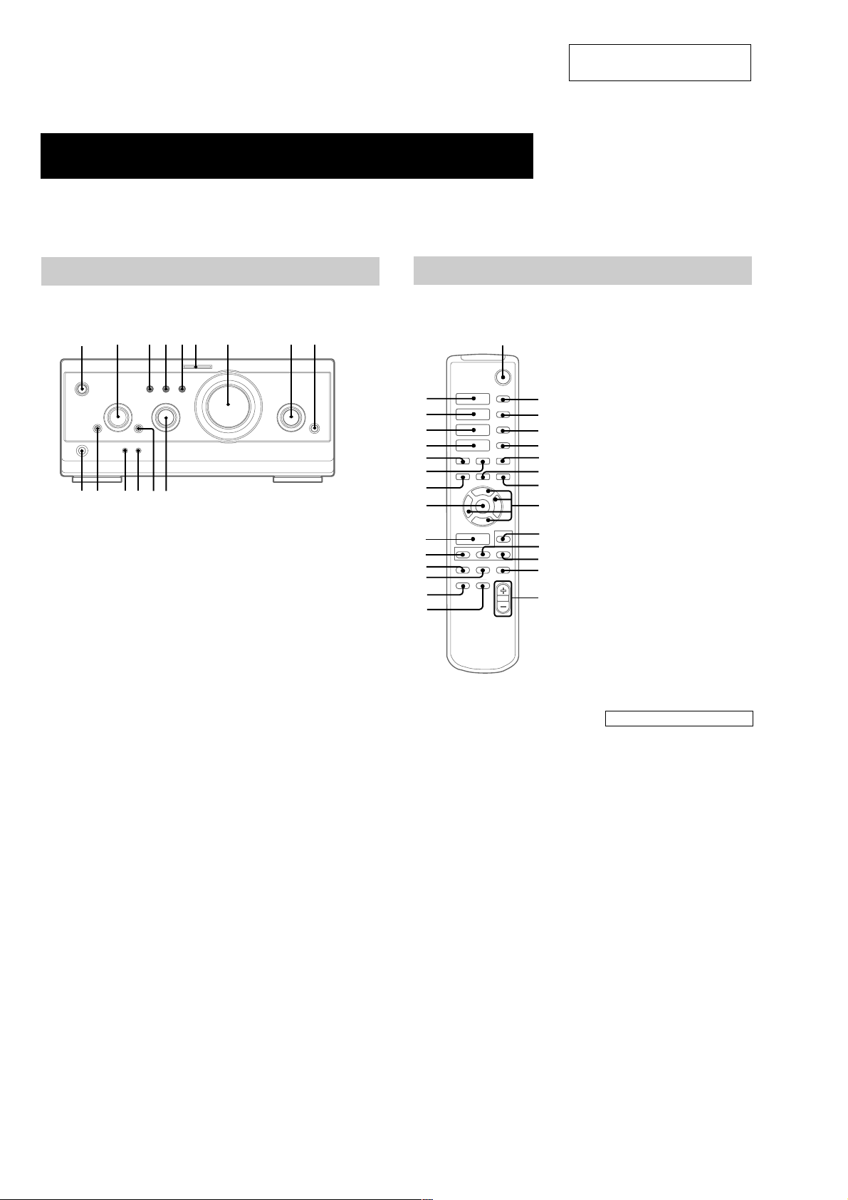
Parts Identification
The items are arranged in alphabetical order.
Refer to the pages indicated in parentheses ( ) for details.
SECTION 2
GENERAL
This section is extracted from
instruction manual.
Main unit
A/V amplifier
1
O
p
P
o
DIGITAL 9 (28, 32)
ENTER/O/o/P/p 2 (9, 12, 18,
19, 22–27)
EQ qa (24)
EQ ON/OFF qs (9, 24)
FILE SELECT q; (20, 24)
FUNCTION 8 (9, 11, 12, 17, 18,
28)
GROOVE 5 (20)
MOVIE MODE 4 (20, 21)
MULTI CHANNEL DECODING
indicator 6 (22)
MUSIC MODE 3 (20, 21)
PHONES jack qg
SET UP qd (23–26)
SUR qf (22)
VOLUME 7
@/1 (power) 1 (8, 9, 32)
Remote Control
63 4 5 7 82
q;qaqsqdqfqg
9
wk
wj
wh
wg
wf
wd
ws
wa
w;
ql
qk
qj
qh
qg
1
H
hH
hH
.
>
Mm
O
Pp
o
CD H wk (11, 12)
CHECK 3 (12)
CLEAR 4 (12)
2
3
4
5
x
6
7
X
8
9
0
qa
qs
qd
qf
CLOCK/TIMER SELECT qg
(19, 27)
CLOCK/TIMER SET qh (9, 18,
26)
DBFB qd (20)
DISPLAY qk (10, 13, 15, 26, 32)
D.SKIP 2 (11)
ENTER wa (9, 12, 14, 15, 18, 19,
22–27)
EQ qa (24)
EQ ON/OFF qs (9, 24)
FUNCTION w; (9, 11, 12, 17, 18,
28)
GROOVE qj (20)
SET UP q; (23–26)
SLEEP 5 (26)
SUR ql (22)
TAPE A hH wj (16)
TAPE B hH wh (16, 17)
TUNER/BAND wg (14)
TUNING + 7 (14)
TUNING – ws (14)
VOL +/– qf
BUTTON DESCRIPTIONS
@/1 (power) 1
X (pause) 8
x (stop) 6
. (go back) wf
> (go forward) wd
m (rewind) ws
M (fast forward) 7
O/o/P/p 9
4
Page 5
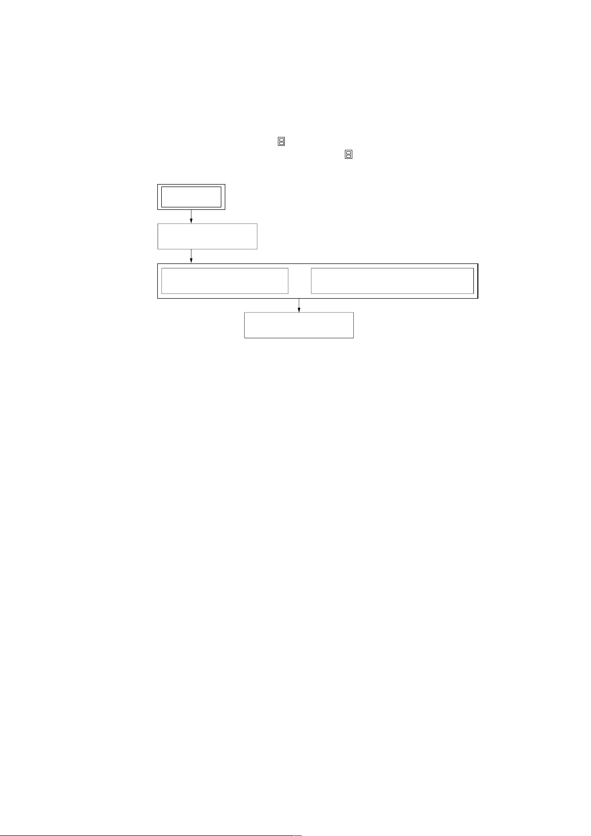
• This set can be disassembled in the order shown below.
3-1. DISASSEMBLY FLOW
Note 1: The process described in can be performed in any order.
Note 2: Without completing the process described in , the next process can not be performed.
SET
3-2. COVER
(Page 6)
TA-S3
SECTION 3
DISASSEMBLY
3-3. FRONT PANEL SECTION
(Page 6)
3-5. FRONT AMP BOARD
(Page 7)
3-4. BACK PANEL (2CH/VCD) SECTION
(Page 7)
5
Page 6
TA-S3
)
)
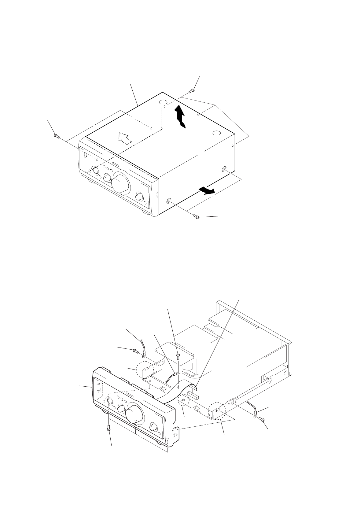
Note: Follow the disassembly procedure in the numerical order given.
3-2. COVER
4
Remove the cover
in the direction of arrow
2
two screws
(case 3 TP2)
3
A
1
three screws
(BVTT3
×
.
A
6)
3
3-3. FRONT PANEL SECTION
2
screw
(BVTP3
6
front panel section
5
×
3
8)
two
claws
lug
3
lug
2
screw
(BVTP3
2
two screws
(case 3 TP2
1
wire (flat type) (23 core)
(CN104)
×
8)
3
lug
5
claw
2
screw
(BVTP3
×
8
4
three screws
(BVTP3
5
two claws
×
8)
6
Page 7
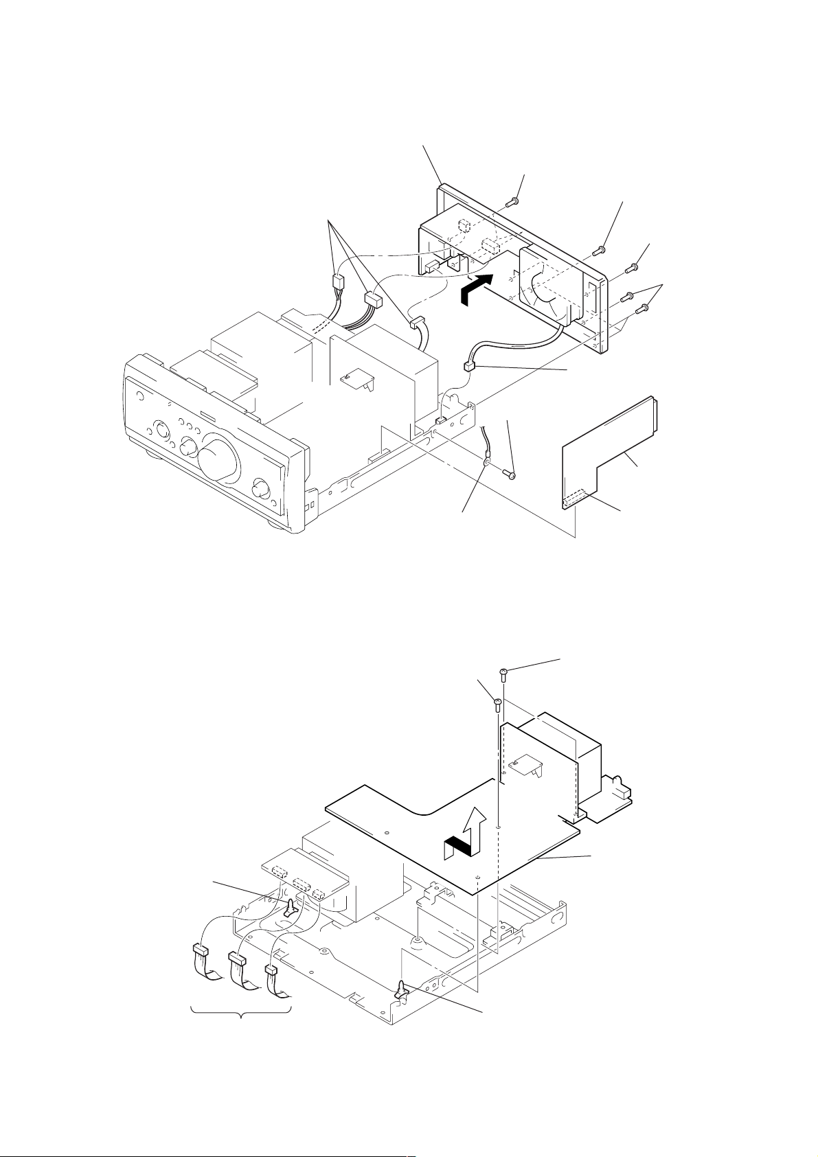
3-4. BACK PANEL (2CH/VCD) SECTION
)
d
7
three connectors
(CN901, 902, 903)
8
back panel (2CH/VCD) section
5
three screws
(BVTP3
6
1
screw
(BVTP3
×
8)
×
8)
6
connector
(CN105)
5
two screws
(BVTP3
1
screw
(BVTP3
5
×
8)
×
8)
four screws
(BVTP3
TA-S3
×
8
3-5. FRONT AMP BOARD
4
PC board holder
3
screw
(BVTP3 × 8)
2
lug
2
two screws
(BVTT3 × 8)
5
4
RELAY board
3
connector
(CN106)
Remove the FRONT AMP boar
in the direction of the arrow.
1
three connector
(CN913, 914, 915)
4
PC board holder
7
Page 8

TA-S3
SECTION 4
TEST MODE
Note: Use following buttons in the test mode.
no mark: Button of amplifier unit (TA-S3)
*1 : Button of tuner unit (ST-S3)
*2 : Button of CD unit (CDP-S3)
[MC Test Mode]
Enter the MC Test Mode
1. Press the I/1 button to turn the power on.
2. While pressing the both [STEREO/MONO] *1 and [2CH/
MULTI C] buttons, press the [MUSIC MODE A] button.
3. “GROOVE” indication blinks on the fluorescent indicator tube
in the midst of MC test mode.
4. This mode has two modes (mode 1/mode 2).
5. To change the modes, press three buttons in the same manner
as entering this mode (step 2). Each time the step 2 operation
is repeated, it changes modes alternately.
6. To distinguish the mode, turn the [VOLUME] knob clockwise
or counterclockwise. Then display is shown as follows.
Mode 1: only “MIN” or “MAX”
Mode 2: “MIN”, “1 to 30” or “MAX”
Releasing the MC Test Mode
T o release from this mode, press the I/1 button or disconnect the
power cord.
[GC Test Mode]
Enter the GC Test Mode
Procedure 1:
1. Press the I/1 button to turn the power on.
2. While pressing the both [STEREO/MONO] *1 and [2CH/
MULTI C] buttons, press the [CLOCK/TIMER] *
3. LEDs and fluorescent indicator tube are all turned on of all
units.
Procedure 2:
1. Press the I/1 button to turn the power on.
2. While pressing the both [PLAY MODE] *2 and x *2 buttons,
press the Z (DISC 1) *2 button.
3. LEDs and fluorescent indicator tube are all turned on of all
units.
Version Display Mode
Procedure:
1. Enter the GC test mode.
2. Each time the [TUNER MEMORY] *1 or [DISC 1] *2 button is
pressed, microcomputer or mechanism deck version is displayed of each unit.
3. Press the [TUNING +] *1 or [DISC 3] *2 button to detail is
displayed the version.
Key Check Mode
Procedure:
1. Enter the GC test mode.
2. Press the [TUNING --] *1 or [DISC 2] *2 button to set the key
check mode.
3. In the key check mode, the fluorescent indicator tube displays
“K 0 J 0 V 0”. Each time a button is pressed, “K” value increases. However , once a button is pressed, it is no longer tak en
into account.
“J” value increases like 1, 2, 3 ... if turn the
knob clockwise, or it decreases like 0, 9, 8 ... if turn the JOG
dial counterclockwise.
“V” value increases like 1, 2, 3 ... if turn the [VOLUME] knob
clockwise, or it decreases like 0, 9, 8 ... if turn the JOG dial
counterclockwise.
1
button.
[FILE SELECT]
Releasing the GC Test Mode
T o release from this mode, press three buttons in the same manner
as entering this mode or disconnect the power cord.
8
Page 9

MEMO
TA-S3
9
Page 10

TA-S3
B
These are omitted.
CE
Q
d
SECTION 5
DIAGRAMS
5-1. NOTE FOR PRINTED WIRING BOARDS AND SCHEMATIC DIAGRAMS
Note on Printed Wiring Boards:
• X : parts extracted from the component side.
• Y : parts extracted from the conductor side.
f
•
• : Pattern from the side which enables seeing.
• Indication of transistor.
: internal component.
Note on Schematic Diagram:
• All capacitors are in µF unless otherwise noted. pF: µµF
50 WV or less are not indicated except for electrolytics
and tantalums.
• All resistors are in Ω and 1/
specified.
f
•
• 2 : nonflammable resistor.
• 5 : fusible resistor.
• C : panel designation.
Note: The components identified by mark 0 or dotted line
• A : B+ Line.
• B : B– Line.
• Voltages are dc with respect to ground under no-signal
• V oltages are taken with a VOM (Input impedance 10 MΩ).
• Signal path.
: internal component.
with mark 0 are critical for safety.
Replace only with part number specified.
conditions.
no mark : Power on
Voltage variations may be noted due to normal production tolerances.
F : AUDIO
4
W or less unless otherwise
• Circuit Boards Location
PANEL board
AC OUTPUT board
AC INPUT board
SUB TRANS board
THP board
RELAY boar
FRONT AMP board
10
Page 11

5-2. PRINTED WIRING BOARDS – FRONT AMP Section – • See page 10 for Circuit Boards Location.
1 2 3 4 5 6 7 8 9 10 11 12 13 14 15 16
A
FRONT AMP BOARD
B
THP BOARD
C
R885
Q881
Q883
EE
R881
D
+
–
IMPEDANCE
USE 6 – 16
Ω
(Page 16)
L
R
SUB TRANS
BOARD
CN903
+
–
A
FRONT SPEAKER
E
F
C861
C862
TM101
NO109
3
C993
D924
C927
G
C914
D992
22
191
JW
JW
H
D990
I
SYSTEM CONTROL 1
FROM ST-S3
CN107
J
JW187
D980
R812
R862
D998
C808
IC924
1
D925
D926
D993
185
JW
JW39
C859
C858
C990
C925
C994
C992
20
JW
186
JW
36
JW
R904
R883
D881
R815
C809
R814
L811
15
IC923
31
JW13
JW188
R991
R992
R908
JW18
D923
D991
21
JW
29
38
28
JW
JW
JW
35
34
JW
JW
R903
E
Q902
R905
AC OUTPUT
(Page 16)
C837
R887
L861
D981
JW192
C926
JW15
JW197
D996
JW16
JW17
C991
31
30
37
JW
JW
JW
E
Q903
BOARD
CN915
D831
R889
JW3
RY881
6
JW
JW10
JW9
JW11
JW12
R843
R842
R841
R972
R971
R973
D994 D995
D997
JW196
JW19
C1101
71
CN105
E
R974
R970
R969
D974
D975
D970
D971
42
41
JW
JW
C1102
JW40
C1100
E
C941
32
JW
13
Q904
M
(FAN)
R906
NO101
7
JW
D973
D972
43
JW
8
JW
Q842
Q841
Q963
Q962
C964
44
45
JW
JW
C1103
R907
E
48
E
JW
E
E
46
183
184
JW
JW
JW
AC OUTPUT
BOARD
F
CN914
(Page 16)
THP841
CN999
JW47
NO110
12
R967
199
JW
50
JW
52
51
JW
JW
IC801
182
JW
C961
59
JW
JW60
R963
JW66
R968
R853
R852
C852
C853
R851
69
68
JW
JW
1-682-168-
54
JW
R964
C812
JW189
JW67
C854
JW70
11
(21)
53
JW
55
JW
56
JW
57
JW
R858
C962
R854
R855
R805
R857
JW61
JW62
D851
R859
R965
C803
Q961
D963
R803
72
C851
JW
71
JW
74
73
JW
JW
JW81
JW82
JW84
JW85
JW86
JW87
83
JW88
JW
JW89
JW90
JW91
JW92
JW93
58
JW
Q851
E
JW63
R856
C856
C963
R966
E
R802
C804
75
JW
CN106
JW94
JW95
JW96
JW97
D802
JW99
JW64
C857
JW65
JW78
EPT902
C806
R892
R807
R806
R809
E
R808
R804
C801
76
JW
C807
D801
Q801
R801
C802
TA-S3
• Semiconductor Location
15
NO102
D911
C911
C956
(Page
JW138
Ref. No. Location
G
AC OUTPUT
BOARD
CN113
16)
D801 H-7
D802 G-7
D821 I-10
D831 D-3
D851 H-7
D871 I-11
D881 D-3
D911 B-10
D923 H-3
D924 G-2
JW139
JW140
D925 G-2
D926 G-2
D963 I-6
R951
R952
D970 H-3
D971 I-3
D972 I-4
D973 H-4
D974 H-3
(CHASSIS)
D
CN700
14)
D975 H-3
CLP1001
601
JW
JW141
JW143
JW880
JW145
101
100
102
JW
JW
JW
119
JW
105
104
103
JW
JW
JW
107
106
JW
JW
49
JW
JW98
C1037
R891
C811
111
JW
79
JW
80
JW
(CHASSIS)
113
JW
C1036
Q895
EEE
108
JW
R898
E
Q896
Q891
C891
E
117
JW
116
114
115
JW
JW
JW
LP902
Q897R897C893
Q894
C892
R895
R896
R894
126
E
JW
Q892
JW125
JW127
JW128
JW130
JW131
JW132
134
136
135
133
JW
JW
JW
JW
R910
JW148
120
JW
123
122
JW
JW
E
Q893
R911
JW180
R912
R924
R925
R926
R927
E
D821
Q822
R880
R877
C872
R878
R916
C871
JW193
JW181
198
JW
IC310
JW167
JW168
R830
R826
R876
JW161
R879
JW150
C951
JW147
R821
D871
R827
R825
E
Q821
E
Q871
R875
R871
JW142
EPT901
C987
(CHASSIS)
C952
JW146
JW149
CN104
23
22
JW152
JW153
JW151
R923
JW154
R921
JW194
JW169
JW155
R920
JW156
R919
JW157
R918
JW158
R917
JW159
JW160
JW195
R913
C924
JW163
JW166
JW190
JW170
JW172
JW173
179
JW
JW174
JW175
JW176
JW177
JW162
JW178
R914
C917
C916
C920
R915
C915
C919
JW164
C918
C821
JW109
JW165
1-680-749-
PANEL BOARD
(Page
11
(21)
Ref. No. Location
D980 J-2
D981 F-3
D990 H-2
D991 H-2
D992 H-2
D993 H-2
D994 H-3
D995 H-3
D996 H-3
D997 H-3
IC310 H-10
IC801 H-5
IC923 F-3
IC924 F-2
Q801 H-7
Q821 I-10
Q822 I-10
SYSTEM CONTROL 2
FROM ST-S3
603
JW
602
JW
CN110
Ref. No. Location
Q841 G-4
Q842 G-4
Q851 G-7
Q871 I-11
Q881 D-3
Q883 D-3
Q891 H-9
Q892 H-9
Q893 H-10
Q894 G-9
Q895 G-9
Q896 H-9
Q897 G-9
Q902 J-3
Q903 J-3
Q904 J-4
Q961 H-7
Q962 H-4
Q963 G-4
RELAY BOARD
1-680-755-
(21)
CN111
11
1111
Page 12

TA-S3
5-3. SCHEMATIC DIAGRAM – FRONT AMP Section (1/2) –
NO109
5P
SYSTEM CONTROL 2
FROM ST-S3
SYSTEM CONTROL 1
FROM ST-S3
CN110
19P
SR-OUT
S-GND
SL-OUT
CENTER-GND
CENTER-OUT
FR-OUT
FRONT-GND
FL-OUT
MIC-GND
MIC-SIG
DBFB FEEDBACK
CHASSIS CHASSIS
POWER KEY
EXP-CLK
EXP-LAT
EXP-OUT DATA
EXP-IN DATA
KEY0 TA
CLP1001
(CHASSIS)
DBFB FEEDBACK
EXP-OUT DATA
(FAN)
FRONT-GND
POWER KEY
EXP-IN DATA
(Page 15)
(Page 17)
FR-IN
FL-IN
MIC-GND
MIC-SIG
EXP-CLK
EXP-LAT
KEY0 TA
NC
CN111
14P
SUB-AC
SUB-AC
RELAY-UNREG
STBY RELAY
DGND
JOG2-B(FIELD SELECT)
JOG2-A(FIELD SELECT)
JOG1-B(FUNCTION)
JOG1-A(FUNCTION)
VOLA
VOLB
AC HIGH
AC HIGH
AC LOW
AC LOW
VP
VF
VF
CT
CT
REG GND
D+5.7V
D-GND
EVER+5V
M(A)-GND
CN107
20P
D970
FR-IN
FRONT-GND
FL-IN
MIC-GND
MIC-SIG
DBFB FEEDBACK
CHASSIS
POWER KEY
EXP-CLK
EXP-LAT
EXP-OUT DATA
EXP-IN DATA
KEY0 TA
NC
CN106
14P
FAN+
FAN-
CN105
3P
CN104
23P
HP-SW
HP-L
HP-GND
HP-R
JOG1-B
JOG1-A
JOG2-B
JOG2-A
VOL3-A
VOL3-B
POWER KEY
KEY0
LED-POWER
LED-SUR
LED-EQ
LED-DCS_A
LED-DCS_B
LED-DCS_C
LED-BLUE
D GND
EVER+5V
+12V
MIC
11ES2-NTA2B
D971
11ES2-NTA2B
TP166
TP167
TP192
D972
11ES2-NTA2B
C941
AC1
AC2
RE
X10
D973
11ES2-NTA2B
0.1
Q903
2SB1116
Q902,903
FAN MOTOR
DRIVE
TP204
TP202
TP200
TP198
TP196
TP194
TP190
TP188
TP181
TP179
TP177
TP175
TP173
TP171
TP169
TP165
TP163
TP158
TP156
TP154
TP152
TP150
TP148
TP146
TP144
TP142
TP160
TP205
TP203
TP201
TP199
TP197
TP195
TP193
TP191
TP189
TP187
D974
TP180
TP178
TP176
TP174
TP172
TP170
TP168
TP164
TP162
TP157
TP155
TP153
TP151
TP149
TP147
TP145
TP143
TP159
11ES2-NTA2B
R905
2.2k
C1100
C1102
C1103
C1101
D975
0.1
0.1
0.1
0.1
11ES2-NTA2B
Q902
2SC2785
(1/2)
TP161 TP141
REGULATOR
R903
10k
R904
R907
100k
2.2k
2SC2001
Z3
+5.6V REGULATOR
OGI
IC924
C994
D981
11ES2-NTA2
D980
11ES2-NTA2
T3
NJM78L05A-T3
C927
220
10V
100
10V
B
B
C914
R908
2.2k
1
50V
11ES2
1SS133T
1SS133T
C993
D924
470
16V
C926
100
16V
D925
R991
1k
-72
R992
D926
1k
-72
JOG2-B
JOG2-A
JOG1-B
JOG1-A
VOL-A
VOL-B
Z3
Z2
Z5
Z4
Z1
Z7
Z6
T1
T2
MIC-SIG
PWR-KEY
CLK
LAT
D-I
D-O
KEY0
Q904
Z10
R906
1k
T4
X8
JOG1-B
JOG1-A
JOG2-B
JOG2-A
VOL-A
VOL-B
PWR-KEY
KEY0
X1
X2
X3
X4
X5
X6
X7
MIC-SIG
D998
D991
11ES2-NTA2
B
D993
11ES2-NTA2
B
IC923 D994D995
NJM78L12A-T3 11ES2-NTA2
OGI
+12V REGULATOR
Z2
Z3
D990
11ES2-NTA2
B
D992
11ES2-NTA2
B
D923
11ES2
C925
10
50V
C990
0.1
C919
C918
10
0.1
50V
C917
R911
100p
100
CLK
R912
X8
X9
BN1F4M
MUTING
CONTROL
100
R917
330
R918
330
R919
330
R920
330
R921
330
R914
100
C872
R880
0.47
50V
Q822
R830
LAT
X6
X5
X4
X3
X2
X7
R913
47k
R915
47k
C924
0.001
D821
1SS133T-72
RE
AC2
C992
0.1
AC1
Z10
C916
100p
C920
0.1
TP250
TP251
R879 D871 R827
100k 1SS133T-72 22k
R878
1M
4.7k
R826
1k
R876
1k
11ES2-NTA2
B
D997 D996
11ES2-NTA2B11ES2-NTA2
C991
330
25V
IC310
PT8300-S
SYSTEM
CONTROLLER
Q821
2SC2878
Q871
2SC2878
Q821,871
MUTING
Z2
Z1
Z2
Z3
Z4
Z5
Z6
Z7
TP106
TP104
TP102
TP107
TP105
TP103
TP101
AC4(HIGH)
AC4(HIGH)
AC3(LOW)
AC3(LOW)
NO101
7P
VP
VF
VF
(Page 17)
B
B
2
3
R910
TP256
100
D-I
R916
100
TP255
R923
1k
C915
TP253
100p
TP252
R927
D-O
47k
X10
R926
10k
X11
R925
X12
47k
X1
R924
47k
TP254
(Page 13)
4
R877
22k
C821
R821
4.7
560
100V
2W
R825
56
R875
56
C871
R871
4.7
560
100V
2W
6
7
8
(Page 17)
11
1212
Page 13

5-4. SCHEMATIC DIAGRAM – FRONT AMP Section (2/2) –
(2/2)
POWER AMP
IC801
STK402-090S
2
C801
R801
4.7
1k
T2
3
T1
(Page 12)
50V
C803
100p
R803
C804
R802C802
56k220p
C852 R852
C811
0.01
220p 56k
C851
R851
4.7
1k
50V
2SC1841
AMP ON
SWITCH
R965
15k
D963
1SS133T-72
C854
47
10V
R853
C853
100p
Q961
R966
33k
C963
100
10V
R968
1
270
47
10V
C812
0.01
270
R963R964
C962 C961
100
100V
R804
R854
100100
100
100V
56k
56k
R806
R807
15k
R857
15k
1/4W
R856
1k
D801
D851
1k
R967
10k
1SS133T-72
1SS133T-72
TA-S3
R841
100k
NO110 CN999
R842
X11
R885
10k
Q881,883
RELAY DRIVE
R887
100k
68k
R843
68k
D911
JW880
Q881
2SA1175
D5SBA20
C951
3300
63V
C952
3300
63V
R881
820
2W
R883
47k
2SC2785
1SS133T-72
Q883
R951
100k
R952
100k
R812
RY881
R814R815
47k47k
D881
D831
1SS133T-72
C837
4.7
50V
1/2W
L811
L861
4.7
R862
4.7
1/2W
C861 C862
0.01 0.01
C809C808
0.10.1
C858 C859
0.1 0.1
C911
0.1
100V
C912
0.1
100V
Q841
2SC1841
Q842
2SC2785TP
Q841,842
THERMAL DETECT
R971
2.2k
Q962
2SA988
Q962,963
AMP ON/OFF
CONTROL
R970
100k
C964
R969
47
22k
50V
R889
R805
0.22/0.22
5W
R809
10
1/2W
C806
0.068
Q801
2SC2785
OVER LOAD
DETECT
R808
100k
R858
100k
2SC2785
OVER LOAD
DETECT
C807
0.068
C857
0.068
C856
0.068
Q851
R859
10
1/2W
R855
0.22/0.22
5W
10k
X12
Y5
T4
Q963
2SC1841
R972
22k
R973 R974
2.2k 10k
2P 2P
C987
0.1
TP108
TP109
TP110
TP112
TP114
TP115
TP116
TP117
EPT901
AC1-GND
AC2-GND
R-GND
L-GND
THP841
(CHASSIS)
NO102
5P
AC1
AC1
(Page 17)
TM101
4P
R-CH
L-CH
(CHASSIS)
(CHASSIS)
R
L
FRONT SPEAKER
IMPEDANCE
USE 6-16 Ω
4
R898
T3
2SC2785
6
7
8
11
X9
4.7k
Q896
2SC2785
Q894-897
PROTECTOR
Q897
Q894
2SC2785
Q895
2SC2785
C893
R897
100
22k
10V
Q893
2SA1175
PROTECT
DETECT
R896
33k
C892
R895
2.2
10k
50V
R894
10k
Q891Q892
2SC27852SC2785
C891
100
10V
Q891,892
DC DETECT
R892R891
5
Y
D802
1SS133T
-72
68k56k
4
Y
EPT902
(CHASSIS)
The components identified by mark 0 or dotted
line with mark 0 are critical for safety.
1313
Replace only with part number specified.
Page 14

TA-S3
5-5. PRINTED WIRING BOARDS – CONTROL Section – • See page 10 for Circuit Boards Location.
1 2 3 4 5 6 7 8 9 10 11
R724
C781
PANEL BOARD
A
NO781
21
B
JW501
C701
C702
FUNCTION
C
S701
ROTARY ENCODER
DIGITAL
S715
R714
D
13
JW707
JW509
22
23
E
VOLUME
S703
ROTARY ENCODER
13
JW506
JW507
C705
CN700
FRONT AMP
D
JW512
BOARD
CN104
C706
JW513
JW514
JW511
JW515
(Page 11)
JW516
JW524
JW517
NO780
JW704
FB708
Q701
R709
D781
21
R708
E
Q702
MULTI CHANNEL
DECODING
D706, S714
2CH/MULTI
R707
E
JW519
C
JW705
JW525
D706
S714
JW518
CLP703
(CHASSIS)
R713
S713
D705, S713
MOVIE MODE
S702
ROTARY ENCODER
13
C703
FILE SELECT
D705
B
R712
R711
C704
JW521
D704
S712
JW520
D704, S712
MUSIC MODE
A
D703, S711
EQ
D703
JW522
S711
R720
R710
R721
S719
EQ ON/OFF SET UP
NO711
13
NO710
13
ENTER
B
S718
S723
R715
R718R719
R716
R717
v
b
V
D702, S710
SUR
D702
S710
D701, S705
FB704
FB706
C711
I/1
D701
S705
FB705
(CHASSIS)
C710
C712
CLP702
1-680-754-
11
(21)
J703
PHONES
• Semiconductor
Location
Ref. No. Location
D701 B-11
D702 C-10
D703 C-8
D704 B-8
D705 B-7
D706 B-6
D781 A-6
Q701 C-6
Q702 C-6
1414
Page 15

5-6. SCHEMATIC DIAGRAM – CONTROL Section –
S701 S702 S703
FUNCTION FILE SELECT VOLUME
C701
0.01
D
N
G
1A
1B
C702
0.01
A6
A5
C703
0.01
D
N
B
A
G
2
2
C704 C705 C706
0.01 0.01 0.01
A4
A3
TA-S3
ROTARY ENCODERROTARY ENCODERROTARY ENCODER
D
N
G
3A
3B
A2
A1
A9
S705
A8
R716 R717 R718 R719
2.2k 2.7k 3.9k 5.6k
S723
ENTER
NO710
3P
NO711
3P
R721R720R715R714R713R712R711R710R709
15k8.2k1.5k1.2k1k820560470270
J703
PHONES
(CHASSIS)
CLP702
C711
0.01
FB706
FB705
FB704
C710
0.001
C712
0.001
D701
SEL5223S
-TP15
LED-POWER
LED-SUR
EQSUR
CINEMA
STUDIO
LED-EQ
CINEMA
STUDIO
LED-DCS_A
CINEMA
STUDIO
S718S719S715S714S713S712S710 S711
Q702
BN1F4M
JW704
SET UPEQ ON/OFF
R707
330
Q701
BA1A4M
NO780 NO781
2P 2P
MIC
+12V
EVER+5V
D GND
LED-BLUE
LED-DCS_C
LED-DCS_B
LED-DCS_A
LED-EQ
LED-SUR
LED-POWER
KEY0
POWER KEY
VOL3-B
VOL3-A
JOG2-A
JOG2-B
JOG1-A
JOG1-B
HP-R
HP-GND
HP-L
HP-SW
D781
SEL5E20C
MULTI CHANNEL
DECODING
CN700
23P
C781
0.01
(Page 12)
DIGITALCBAEQSUR
JW705FB708
D706D705D704D703D702
SEL5923ASEL5923ASEL5923ASEL5923ASEL5923A
CINEMA
STUDIO
BA
C
LED-DCS_B
LED-DCS_C
R708
100
LED-BLUE
LED-DCS_C
LED-DCS_B
LED-DCS_A
LED-EQ
LED-SUR
LED-POWER
A8
A9
A1
A2
A3
A4
A5
A6
LED-BLUE
Q701,702
LED DRIVE
1515
Page 16

TA-S3
5-7. PRINTED WIRING BOARDS – POWER Section – • See page 10 for Circuit Boards Location.
(AC IN)
SUB TRANS BOARD
JW801
CN902
JW803
JW938
JW804
JW805
JW806
JW807
JW808
JW809
JW810
JW811
JW812
3
CN915
1
C901
E
RY901
T901
POWER
TRANSFORMER
(SUB)
FRONT AMP
BOARD
NO101
(Page 11)
D901
JW907
JW913
LP102
21
JW920
1
2
NO921
JW930
JW802
T911
POWER
TRANSFORMER
(MAIN)
JW903
CN901
2
1
JW902
JW905
AC OUTPUT BOARDAC INPUT BOARD
F937
Q901
E
R901
R902
1-680-751-
CN903
1
FRONT AMP
BOARD
A
NO109
(Page 11)
5
11
(21)
JW922
1-680-752-
(21)
F931
1
FRONT AMP
11
(21)
G
F
BOARD
NO102
(Page 11)
FRONT AMP
BOARD
NO101
(Page 11)
CN913
JW961
5
F934
11
F935
F936
4
CN914
1
1-680-754-
1616
Page 17

5-8. SCHEMATIC DIAGRAM – POWER Section –
TA-S3
(Page 13)
(Page 12)
(Page 12)
AC1
AC1-GND
AC1
AC2
AC2-GND
AC2
CN913
CN915
3P
VP
AC4(HIGH)
AC4(HIGH)
AC3(LOW)
AC3(LOW)
VF
VF
CN914
T911
F931
T8AL
250V
5P
F934
T8AL 250V
F936F935
T2.5AL 250VT2.5AL 250V
F937
T4AL 250V
4P
JW938
POWER
TRANSFORMER
(MAIN)
(Page 12)
JW922
NO921
230 230
NEUTRAL
CN903
5P
SUB-AC
SUB-AC
RELAY-UNREG
STBY RELAY
DGND
CN902
R902
10k
R901
100k
2P
NEUTRAL
JW913 JW907
T901
POWER
TRANSFORMER
(SUB)
Q901
2SC2785
RELAY
DRIVE
C901
0.01
250V
JW905
RY901
JW902
D901
1SS133T
JW903
CN901
2P
(AC IN)
2P
The components identified by mark 0 or dotted
line with mark 0 are critical for safety.
Replace only with part number specified.
1717
Page 18

TA-S3
5-9. IC PIN FUNCTION DESCRIPTION
• FRONT AMP BOARD IC310 PT8300-S (SYSTEM CONTROLLER)
Pin No. Pin Name I/O Description
1 VSS —
2
3
4
5
6
7
8
9
10
11
12
13
14
15
16
17
18
19
20
21
22
23
24
25
26
27
28 VCC
RESET_B I Reset signal input terminal Not used
CLK I Serial data transfer clock signal input from the tuner unit (ST-S3)
LATCH I Serial data latch pulse input from the tuner unit (ST-S3)
LED C O LED drive signal output of the 2CH/MULTI C indicator (D706) “L”: LED on
LED B O LED drive signal output of the MOVIE MODE B indicator (D705) “L”: LED on
LED A O LED drive signal output of the MUSIC MODE A indicator (D704) “L”: LED on
LED EQ O LED drive signal output of the EQ indicator (D703) “L”: LED on
LED SUR O LED drive signal output of the SUR indicator (D702) “L”: LED on
LED BLU O
HP SW I Headphone detection signal input terminal “H”: headphone on
PROTECT I Over load detection signal input for speaker output “L”: over load
LATCHO O Serial data latch pulse output terminal Not used (open)
CLKO O Serial data transfer clock signal output terminal Not used (open)
— — Not used (open)
— — Not used (fixed at “L”)
— — Not used (open)
MUTING O Muting on/off control signal output terminal “L”: muting
LED PW O
SUR RY O
F RY O Relay drive signal output for the front speaker protection “H”: on
STK PW O Power amplifier on/off selection signal output terminal “L”: standby, “H”: on
— — Not used (open)
STBY RY O Standby relay drive signal output terminal “L”: standby, “H”: power on
DATA OUT O Serial data output to the tuner unit (ST-S3)
DATA IN I Serial data input from the tuner unit (ST-S3)
PULLUP — Not used (open)
Ground terminal
LED drive signal output of the MULTI CHANNEL DECODING indicator (D781)
“L”: LED on
LED drive signal output of the I/1 indicator (D701) “L”: LED on
Relay drive signal output for the surround speaker (rear and center) protection “H”: on
Not used (fixed at “H”)
— Power supply terminal (+5V)
Page 19

SECTION 6
EXPLODED VIEWS
NOTE:
• -XX and -X mean standardized parts, so they
may have some difference from the original
one.
• Color Indication of Appearance Parts
Example:
KNOB, BALANCE (WHITE) . . . (RED)
↑↑
Parts Color Cabinet's Color
6-1. COVER SECTION
3
2
• Items marked “*” are not stocked since they
are seldom required for routine service. Some
delay should be anticipated when ordering
these items.
• The mechanical parts with no reference number in the exploded views are not supplied.
• Hardware (# mark) list is given in the last of
the electrical parts list.
#4
4
The components identified by
mark 0 or dotted line with mark
0 are critical for safety.
Replace only with part number
specified.
#1
#1
#1
not supplied
#1
#1
1
Front panel section
5
#1
#1
2
6
not supplied
#1
#1
not supplied
7
Ref. No. Part No. Description Remark
1 1-773-178-11 WIRE (FLAT TYPE) (23 CORE)
2 3-363-099-21 SCREW (CASE 3 TP2)
3 4-232-336-11 COVER
4 4-233-558-01 PANEL (2CH/VCD), BACK (AEP)
1818
Ref. No. Part No. Description Remark
4 4-233-558-11 PANEL (2CH/VCD), BACK (UK)
5 1-680-751-11 SUB TRANS BOARD
6 1-763-072-11 FAN, D. C.
7 1-680-755-11 RELAY BOARD
Page 20

6-2. FRONT PANEL SECTION
)
57
TA-S3
z
B
56
55
supplied with S702
51
52
53
z
A
supplied with S703
56
56
58
(including zA, zB
54
51
Ref. No. Part No. Description Remark
51 4-232-342-01 KNOB (FUNC)
52 4-232-338-01 KNOB (VOL)
53 X-4953-618-1 PANEL ASSY, FRONT
54 4-232-341-01 SHEET (VOL)
supplied with S701
Ref. No. Part No. Description Remark
55 4-232-343-01 BUTTON (ENTER)
56 4-951-620-01 SCREW (2.6X8), +BVTP
57 4-232-344-01 INDICATOR (BLUE)
58 A-4476-220-A PANEL BOARD, COMPLETE
19
Page 21

TA-S3
6-3. CHASSIS SECTION
103
103
#3
109
104
102
101
not supplied
T911
not supplied
not supplied
#1
not supplied
105
#2
#1
106
108
not supplied
not supplied
106
not supplied
not supplied
Ref. No. Part No. Description Remark
101 A-4476-205-A FRONT AMP BOARD, COMPLETE
102 1-680-753-11 AC OUTPUT BOARD
103 4-900-386-01 SCREW
104 1-680-752-11 AC INPUT BOARD
105 1-682-168-11 THP BOARD
106 3-970-608-01 SUMITITE (B3), +BV
20
107
The components identified by mark 0 or dotted
line with mark 0 are critical for safety.
Replace only with part number specified.
Ref. No. Part No. Description Remark
107 4-965-822-01 FOOT
* 108 3-703-244-00 BUSHING (2104), CORD
0 109 1-777-071-81 CORD, POWER (AEP)
0 109 1-790-226-11 CORD, POWER (UK)
0 T911 1-435-936-11 TRANSFORMER, POWER
Page 22

TA-S3
SECTION 7
AC INPUT AC OUTPUT
ELECTRICAL PARTS LIST
FRONT AMP
NOTE:
• Due to standardization, replacements in the
parts list may be different from the parts specified in the diagrams or the components used
on the set.
• -XX and -X mean standardized parts, so they
may have some difference from the original
one.
• RESISTORS
All resistors are in ohms.
METAL: Metal-film resistor.
METAL OXIDE: Metal oxide-film resistor.
F: nonflammable
Ref. No. Part No. Description Remark Ref. No. Part No. Description Remark
1-680-752-11 AC INPUT BOARD
***************
• Items marked “*” are not stocked since they
are seldom required for routine service.
Some delay should be anticipated when ordering these items.
• SEMICONDUCTORS
In each case, u: µ, for example:
uA. . : µA. . uPA. . : µPA. .
uPB. . : µPB. . uPC. . : µPC. .
uPD. . : µPD. .
• CAPACITORS
uF: µF
• COILS
uH: µH
C857 1-136-495-11 FILM 0.068uF 5% 50V
C858 1-136-165-00 FILM 0.1uF 5% 50V
The components identified by
mark 0 or dotted line with mark
0 are critical for safety.
Replace only with part number
specified.
When indicating parts by reference
number, please include the board.
**************************************************************
1-680-753-11 AC OUTPUT BOARD
****************
1-533-217-41 HOLDER, FUSE
< CONNECTOR >
CN913 1-691-767-11 PLUG (MICRO CONNECTOR) 5P
CN914 1-691-766-11 PLUG (MICRO CONNECTOR) 4P
CN915 1-691-765-11 PLUG (MICRO CONNECTOR) 3P
< FUSE >
0 F931 1-533-949-31 FUSE, CYLINDRICAL (TIME LUG) (T8AL/250V)
0 F934 1-533-949-31 FUSE, CYLINDRICAL (TIME LUG) (T8AL/250V)
0 F935 1-533-469-11 FUSE, GLASS TUBE (DIA. 5) (T2.5AL/250V)
0 F936 1-533-469-11 FUSE, GLASS TUBE (DIA. 5) (T2.5AL/250V)
0 F937 1-533-471-11 FUSE, GLASS TUBE (DIA. 5) (T4AL/250V)
**************************************************************
A-4476-205-A FRONT AMP BOARD, COMPLETE
**************************
7-685-646-79 SCREW +BVTP 3X8 TYPE2 N-S
< CAPACITOR >
C801 1-126-963-11 ELECT 4.7uF 20% 50V
C802 1-162-286-31 CERAMIC 220PF 10% 50V
C803 1-162-282-31 CERAMIC 100PF 10% 50V
C804 1-104-664-11 ELECT 47uF 20% 10V
C806 1-136-495-11 FILM 0.068uF 5% 50V
C807 1-136-495-11 FILM 0.068uF 5% 50V
C808 1-136-165-00 FILM 0.1uF 5% 50V
C809 1-136-165-00 FILM 0.1uF 5% 50V
C811 1-162-306-11 CERAMIC 0.01uF 30% 16V
C812 1-162-306-11 CERAMIC 0.01uF 30% 16V
C821 1-107-721-11 ELECT 4.7uF 20% 100V
C837 1-126-963-11 ELECT 4.7uF 20% 50V
C851 1-126-963-11 ELECT 4.7uF 20% 50V
C852 1-162-286-31 CERAMIC 220PF 10% 50V
C853 1-162-282-31 CERAMIC 100PF 10% 50V
C854 1-104-664-11 ELECT 47uF 20% 10V
C856 1-136-495-11 FILM 0.068uF 5% 50V
C859 1-136-165-00 FILM 0.1uF 5% 50V
C861 1-162-306-11 CERAMIC 0.01uF 30% 16V
C862 1-162-306-11 CERAMIC 0.01uF 30% 16V
C871 1-107-721-11 ELECT 4.7uF 20% 100V
C872 1-126-959-11 ELECT 0.47uF 20% 50V
C891 1-104-665-11 ELECT 100uF 20% 10V
C892 1-126-961-11 ELECT 2.2uF 20% 50V
C893 1-104-665-11 ELECT 100uF 20% 10V
C911 1-130-777-00 MYLAR 0.1uF 5% 100V
C912 1-130-777-00 MYLAR 0.1uF 5% 100V
C914 1-115-871-11 ELECT 1uF 20% 50V
C915 1-162-282-31 CERAMIC 100PF 10% 50V
C916 1-162-282-31 CERAMIC 100PF 10% 50V
C917 1-162-282-31 CERAMIC 100PF 10% 50V
C918 1-164-159-11 CERAMIC 0.1uF 50V
C919 1-126-964-11 ELECT 10uF 20% 50V
C920 1-164-159-11 CERAMIC 0.1uF 50V
C924 1-162-294-31 CERAMIC 0.001uF 10% 50V
C925 1-126-795-11 ELECT 10uF 20% 50V
C926 1-126-382-11 ELECT 100uF 20% 16V
C927 1-104-665-11 ELECT 100uF 20% 10V
C941 1-164-159-11 CERAMIC 0.1uF 50V
C951 1-135-516-11 ELECT 3300uF 20% 63V
C952 1-135-516-11 ELECT 3300uF 20% 63V
C961 1-128-563-11 ELECT 100uF 20% 100V
C962 1-128-563-11 ELECT 100uF 20% 100V
C963 1-104-665-11 ELECT 100uF 20% 10V
C964 1-119-943-11 ELECT 47uF 20% 50V
C987 1-164-159-11 CERAMIC 0.1uF 50V
C990 1-164-159-11 CERAMIC 0.1uF 50V
C991 1-126-940-11 ELECT 330uF 20% 25V
C992 1-113-342-11 CERAMIC 0.1uF 50V
C993 1-126-935-11 ELECT 470uF 20% 16V
C994 1-126-176-11 ELECT 220uF 20% 10V
C1100 1-164-159-11 CERAMIC 0.1uF 50V
C1101 1-164-159-11 CERAMIC 0.1uF 50V
C1102 1-164-159-11 CERAMIC 0.1uF 50V
C1103 1-164-159-11 CERAMIC 0.1uF 50V
< CONNECTOR >
CN104 1-784-784-11 CONNECTOR, FFC 23P
21
Page 23

TA-S3
FRONT AMP
Ref. No. Part No. Description Remark
CN105 1-564-506-11 PLUG, CONNECTOR 3P
CN106 1-573-846-11 CONNECTOR, BOARD TO BOARD 14P
CN107 1-794-498-21 SOCKET, CONNECTOR 20P
(SYSTEM CONTROL 1 FROM ST-S3)
< DIODE >
D801 8-719-911-19 DIODE 1SS133T-72
D802 8-719-911-19 DIODE 1SS133T-72
D821 8-719-911-19 DIODE 1SS133T-72
D831 8-719-911-19 DIODE 1SS133T-72
D851 8-719-911-19 DIODE 1SS133T-72
D871 8-719-911-19 DIODE 1SS133T-72
D881 8-719-911-19 DIODE 1SS133T-72
D911 8-719-510-68 DIODE D5SBA204101
D923 8-719-024-99 DIODE 11ES2-NTA2B
D924 8-719-024-99 DIODE 11ES2-NTA2B
D925 8-719-911-19 DIODE 1SS133T-72
D926 8-719-911-19 DIODE 1SS133T-72
D963 8-719-911-19 DIODE 1SS133T-72
D970 8-719-024-99 DIODE 11ES2-NTA2B
D971 8-719-024-99 DIODE 11ES2-NTA2B
D972 8-719-024-99 DIODE 11ES2-NTA2B
D973 8-719-024-99 DIODE 11ES2-NTA2B
D974 8-719-024-99 DIODE 11ES2-NTA2B
D975 8-719-024-99 DIODE 11ES2-NTA2B
D980 8-719-024-99 DIODE 11ES2-NTA2B
D981 8-719-024-99 DIODE 11ES2-NTA2B
D990 8-719-024-99 DIODE 11ES2-NTA2B
D991 8-719-024-99 DIODE 11ES2-NTA2B
D992 8-719-024-99 DIODE 11ES2-NTA2B
D993 8-719-024-99 DIODE 11ES2-NTA2B
D994 8-719-024-99 DIODE 11ES2-NTA2B
D995 8-719-024-99 DIODE 11ES2-NTA2B
D996 8-719-024-99 DIODE 11ES2-NTA2B
D997 8-719-024-99 DIODE 11ES2-NTA2B
< GROUND TERMINAL >
Ref. No. Part No. Description Remark
Q881 8-729-119-76 TRANSISTOR 2SA1175TP-HFE
Q883 8-729-119-78 TRANSISTOR 2SC2785TP-HFE
Q891 8-729-119-78 TRANSISTOR 2SC2785TP-HFE
Q892 8-729-119-78 TRANSISTOR 2SC2785TP-HFE
Q893 8-729-119-76 TRANSISTOR 2SA1175TP-HFE
Q894 8-729-119-78 TRANSISTOR 2SC2785TP-HFE
Q895 8-729-119-78 TRANSISTOR 2SC2785TP-HFE
Q896 8-729-119-78 TRANSISTOR 2SC2785TP-HFE
Q897 8-729-119-78 TRANSISTOR 2SC2785TP-HFE
Q902 8-729-119-78 TRANSISTOR 2SC2785TP-HFE
Q903 8-729-140-04 TRANSISTOR 2SB1116-TP-LK
Q904 8-729-142-46 TRANSISTOR 2SC2001TP-LK
Q961 8-729-140-84 TRANSISTOR 2SC1841TP-PAFAEA
Q962 8-729-140-82 TRANSISTOR 2SA988TP-PAFAEA
Q963 8-729-140-84 TRANSISTOR 2SC1841TP-PAFAEA
< RESISTOR >
R801 1-249-417-11 CARBON 1K 5% 1/4W
R802 1-249-438-11 CARBON 56K 5% 1/4W
R803 1-249-410-11 CARBON 270 5% 1/4W
R804 1-249-438-11 CARBON 56K 5% 1/4W
0 R805 1-234-499-21 ENCAPSULATED COMPONENT 0.22 5W
R806 1-249-417-11 CARBON 1K 5% 1/4W
R807 1-249-431-11 CARBON 15K 5% 1/4W
R808 1-249-441-11 CARBON 100K 5% 1/4W
R809 1-260-076-11 CARBON 10 5% 1/2W
R812 1-260-072-11 CARBON 4.7 5% 1/2W
R814 1-249-437-11 CARBON 47K 5% 1/4W
R815 1-249-437-11 CARBON 47K 5% 1/4W
0 R821 1-216-455-11 METAL OXIDE 560 5% 2W F
R825 1-249-402-11 CARBON 56 5% 1/4W
R826 1-249-417-11 CARBON 1K 5% 1/4W
R827 1-249-433-11 CARBON 22K 5% 1/4W
R841 1-249-441-11 CARBON 100K 5% 1/4W
R842 1-249-439-11 CARBON 68K 5% 1/4W
R843 1-249-439-11 CARBON 68K 5% 1/4W
EPT901 1-537-770-21 TERMINAL BOARD, GROUND
EPT902 1-537-770-21 TERMINAL BOARD, GROUND
< IC >
IC310 6-800-467-01 IC PT8300-S
IC801 8-749-016-94 IC STK402-090S
IC923 8-759-595-88 IC NJM78L12A-T3
IC924 8-759-708-05 IC NJM78L05A-T3
< COIL >
L811 1-420-872-00 COIL, AIR-CORE
L861 1-420-872-00 COIL, AIR-CORE
< TRANSISTOR >
Q801 8-729-119-78 TRANSISTOR 2SC2785TP-HFE
Q821 8-729-231-55 TRANSISTOR 2SC2878AB-TPE2
Q822 8-729-900-63 TRANSISTOR BN1F4M-TP
Q841 8-729-140-84 TRANSISTOR 2SC1841TP-PAFAEA
Q842 8-729-119-78 TRANSISTOR 2SC2785TP-HFE
Q851 8-729-119-78 TRANSISTOR 2SC2785TP-HFE
Q871 8-729-231-55 TRANSISTOR 2SC2878AB-TPE2
22
R851 1-249-417-11 CARBON 1K 5% 1/4W
R852 1-249-438-11 CARBON 56K 5% 1/4W
R853 1-249-410-11 CARBON 270 5% 1/4W
R854 1-249-438-11 CARBON 56K 5% 1/4W
0 R855 1-234-499-21 ENCAPSULATED COMPONENT 0.22 5W
R856 1-249-417-11 CARBON 1K 5% 1/4W
R857 1-249-431-11 CARBON 15K 5% 1/4W
R858 1-249-441-11 CARBON 100K 5% 1/4W
R859 1-260-076-11 CARBON 10 5% 1/2W
R862 1-260-072-11 CARBON 4.7 5% 1/2W
0 R871 1-216-455-11 METAL OXIDE 560 5% 2W F
R875 1-249-402-11 CARBON 56 5% 1/4W
R876 1-249-417-11 CARBON 1K 5% 1/4W
R877 1-249-433-11 CARBON 22K 5% 1/4W
R878 1-249-425-11 CARBON 4.7K 5% 1/4W
R879 1-249-441-11 CARBON 100K 5% 1/4W
R880 1-247-903-00 CARBON 1M 5% 1/4W
0 R881 1-216-456-00 METAL OXIDE 820 5% 2W F
R883 1-249-437-11 CARBON 47K 5% 1/4W
R885 1-249-429-11 CARBON 10K 5% 1/4W
R887 1-249-441-11 CARBON 100K 5% 1/4W
The components identified by mark 0 or dotted
line with mark 0 are critical for safety.
Replace only with part number specified.
Page 24

TA-S3
FRONT AMP PANEL
Ref. No. Part No. Description Remark
R889 1-249-429-11 CARBON 10K 5% 1/4W
R891 1-249-438-11 CARBON 56K 5% 1/4W
R892 1-249-439-11 CARBON 68K 5% 1/4W
R894 1-249-429-11 CARBON 10K 5% 1/4W
R895 1-249-429-11 CARBON 10K 5% 1/4W
R896 1-249-435-11 CARBON 33K 5% 1/4W
R897 1-249-433-11 CARBON 22K 5% 1/4W
R898 1-249-425-11 CARBON 4.7K 5% 1/4W
R903 1-249-429-11 CARBON 10K 5% 1/4W
R904 1-249-441-11 CARBON 100K 5% 1/4W
R905 1-249-421-11 CARBON 2.2K 5% 1/4W
R906 1-249-417-11 CARBON 1K 5% 1/4W
R907 1-249-421-11 CARBON 2.2K 5% 1/4W
R908 1-249-421-11 CARBON 2.2K 5% 1/4W
R910 1-247-807-31 CARBON 100 5% 1/4W
R911 1-247-807-31 CARBON 100 5% 1/4W
R912 1-247-807-31 CARBON 100 5% 1/4W
R913 1-249-437-11 CARBON 47K 5% 1/4W
R914 1-247-807-31 CARBON 100 5% 1/4W
R915 1-249-437-11 CARBON 47K 5% 1/4W
R916 1-247-807-31 CARBON 100 5% 1/4W
R917 1-249-411-11 CARBON 330 5% 1/4W
R918 1-249-411-11 CARBON 330 5% 1/4W
R919 1-249-411-11 CARBON 330 5% 1/4W
R920 1-249-411-11 CARBON 330 5% 1/4W
R921 1-249-411-11 CARBON 330 5% 1/4W
R923 1-249-417-11 CARBON 1K 5% 1/4W
R924 1-249-437-11 CARBON 47K 5% 1/4W
R925 1-249-437-11 CARBON 47K 5% 1/4W
R926 1-249-429-11 CARBON 10K 5% 1/4W
R927 1-249-437-11 CARBON 47K 5% 1/4W
R951 1-249-441-11 CARBON 100K 5% 1/4W
R952 1-249-441-11 CARBON 100K 5% 1/4W
0 R963 1-212-881-11 FUSIBLE 100 5% 1/4W F
0 R964 1-212-881-11 FUSIBLE 100 5% 1/4W F
R965 1-249-431-11 CARBON 15K 5% 1/4W
R966 1-249-435-11 CARBON 33K 5% 1/4W
R967 1-249-429-11 CARBON 10K 5% 1/4W
0 R968 1-202-972-61 FUSIBLE 1 5% 1/4W F
R969 1-249-433-11 CARBON 22K 5% 1/4W
R970 1-249-441-11 CARBON 100K 5% 1/4W
R971 1-249-421-11 CARBON 2.2K 5% 1/4W
R972 1-249-433-11 CARBON 22K 5% 1/4W
R973 1-249-421-11 CARBON 2.2K 5% 1/4W
R974 1-249-429-11 CARBON 10K 5% 1/4W
R991 1-249-417-11 CARBON 1K 5% 1/4W
R992 1-249-417-11 CARBON 1K 5% 1/4W
< RELAY >
RY881 1-515-920-11 RELAY
< TERMINAL >
TM101 1-694-677-12 TERMINAL BOARD (4P)
(FRONT SPEAKER IMPEDANCE USE 6-16Ω)
**************************************************************
Ref. No. Part No. Description Remark
A-4476-220-A PANEL BOARD, COMPLETE
**********************
< CAPACITOR >
C701 1-162-306-11 CERAMIC 0.01uF 30% 16V
C702 1-162-306-11 CERAMIC 0.01uF 30% 16V
C703 1-162-306-11 CERAMIC 0.01uF 30% 16V
C704 1-162-306-11 CERAMIC 0.01uF 30% 16V
C705 1-162-306-11 CERAMIC 0.01uF 30% 16V
C706 1-162-306-11 CERAMIC 0.01uF 30% 16V
C710 1-162-294-31 CERAMIC 0.001uF 10% 50V
C711 1-162-306-11 CERAMIC 0.01uF 30% 16V
C712 1-162-294-31 CERAMIC 0.001uF 10% 50V
C781 1-162-306-11 CERAMIC 0.01uF 30% 16V
< CONNECTOR >
CN700 1-784-745-11 CONNECTOR, FFC 23P
< DIODE >
D701 8-719-058-04 LED SEL5223S-TP15 (I/1)
D702 8-719-057-97 LED SEL5923A-TP15 (SUR)
D703 8-719-057-97 LED SEL5923A-TP15 (EQ)
D704 8-719-057-97 LED SEL5923A-TP15 (MUSIC MODE, A)
D705 8-719-057-97 LED SEL5923A-TP15 (MOVIE MODE, B)
D706 8-719-057-97 LED SEL5923A-TP15 (2CH/MULTI, C)
D781 8-719-084-07 LED SEL5E20CTP15
(MULTI CHANNEL DECODING)
< JACK >
J703 1-691-293-21 JACK (PHONES)
< TRANSISTOR >
Q701 8-729-900-80 TRANSISTOR BA1A4M-TP
Q702 8-729-900-63 TRANSISTOR BN1F4M-TP
< RESISTOR >
R707 1-249-411-11 CARBON 330 5% 1/4W
R708 1-247-807-31 CARBON 100 5% 1/4W
R709 1-249-410-11 CARBON 270 5% 1/4W
R710 1-249-413-11 CARBON 470 5% 1/4W
R711 1-249-414-11 CARBON 560 5% 1/4W
R712 1-249-416-11 CARBON 820 5% 1/4W
R713 1-249-417-11 CARBON 1K 5% 1/4W
R714 1-249-418-11 CARBON 1.2K 5% 1/4W
R715 1-249-419-11 CARBON 1.5K 5% 1/4W
R716 1-249-421-11 CARBON 2.2K 5% 1/4W
R717 1-249-422-11 CARBON 2.7K 5% 1/4W
R718 1-249-424-11 CARBON 3.9K 5% 1/4W
R719 1-249-426-11 CARBON 5.6K 5% 1/4W
R720 1-249-428-11 CARBON 8.2K 5% 1/4W
R721 1-249-431-11 CARBON 15K 5% 1/4W
< SWITCH >
S701 1-473-534-11 ENCODER, ROTARY (FUNCTION)
S702 1-473-534-11 ENCODER, ROTARY (FILE SELECT)
S703 1-473-392-11 ENCODER, ROTARY (VOLUME)
S705 1-771-410-21 SWITCH, TACTILE (I/1)
S710 1-771-410-21 SWITCH, TACTILE (SUR)
The components identified by mark 0 or dotted
line with mark 0 are critical for safety.
Replace only with part number specified.
23
Page 25

TA-S3
PANEL RELAY SUB TRANS THP
Ref. No. Part No. Description Remark
S711 1-771-410-21 SWITCH, TACTILE (EQ)
S712 1-771-410-21 SWITCH, TACTILE (MUSIC MODE, A)
S713 1-771-410-21 SWITCH, TACTILE (MOVIE MODE, B)
S714 1-771-410-21 SWITCH, TACTILE (2CH/MULTI, C)
S715 1-771-410-21 SWITCH, TACTILE (DIGITAL)
S718 1-771-410-21 SWITCH, TACTILE (SET UP)
S719 1-771-410-21 SWITCH, TACTILE (EQ ON/OFF)
S723 1-771-879-11 SWITCH, TACTILE (ENTER)
**************************************************************
1-680-755-11 RELAY BOARD
************
< CONNECTOR >
CN110 1-793-351-41 SOCKET, CONNECTOR 19P
(SYSTEM CONTROL 2 FROM ST-S3)
* CN111 1-573-828-11 CONNECTOR, BOARD TO BOARD 14P
**************************************************************
1-680-751-11 SUB TRANS BOARD
****************
< CAPACITOR >
0 C901 1-113-925-11 CERAMIC 0.01uF 20% 250V
Ref. No. Part No. Description Remark
MISCELLANEOUS
**************
1 1-773-178-11 WIRE (FLAT TYPE) (23 CORE)
6 1-763-072-11 FAN, D. C.
0 109 1-777-071-81 CORD, POWER (AEP)
0 109 1-790-226-11 CORD, POWER (UK)
0 T911 1-435-936-11 TRANSFORMER, POWER
************************************************************
**************
HARDWARE LIST
**************
#1 7-685-646-79 SCREW +BVTP 3X8 TYPE2 N-S
#2 7-685-650-79 SCREW +BVTP 3X16 TYPE2 IT-3
#3 7-685-872-09 SCREW +BVTT 3X8 (S)
#4 7-685-871-01 SCERW +BVTT 3X6 (S)
< CONNECTOR >
CN901 1-564-321-00 PIN, CONNECTOR 2P
* CN902 1-564-321-21 PIN, CONNECTOR 2P
CN903 1-691-767-11 PLUG (MICRO CONNECTOR) 5P
< DIODE >
D901 8-719-911-19 DIODE 1SS133T-72
< TRANSISTOR >
Q901 8-729-119-78 TRANSISTOR 2SC2785TP-HFE
< RESISTOR >
R901 1-249-441-11 CARBON 100K 5% 1/4W
R902 1-249-429-11 CARBON 10K 5% 1/4W
< RELAY >
0 RY901 1-755-276-11 RELAY, POWER
< TRANSFORMER >
0 T901 1-435-824-11 TRANSFORMER, POWER
**************************************************************
1-682-168-11 THP BOARD
**********
< CONNECTOR >
* CN999 1-564-517-11 PLUG, CONNECTOR 2P
< THERMISTOR (POSITIVE) >
THP841 1-807-796-11 THERMISTOR
**************************************************************
24
The components identified by mark 0 or dotted
line with mark 0 are critical for safety.
Replace only with part number specified.
Page 26

MEMO
TA-S3
25
Page 27

TA-S3
REVISION HISTORY
Clicking the version allows you to jump to the revised page.
Also, clicking the version at the upper right on the revised page allows you to jump to the next revised
page.
Ver. Date Description of Revision
1.0 2001.05 New
 Loading...