

Sony TA-EX66, TA-EX77 Service Manual
MICROFILM
AEP Model
UK Model
E Model
SERVICE MANUAL
TA-EX66/EX77
INTEGRATED STEREO AMPLIFIER
T A-EX66/EX77 is the amplifier section
in MHC-EX66, DHC-EX77MD/MD77.
SPECIFICA TIONS
Photo: TA-EX77 (AEP, UK model)
General
Power requirements
AEP, UK model: 220 – 230 V AC, 50/60 Hz
HK, SP model: 220 – 240 V AC, 50/60 Hz
Power consumption 125 watts
Design and specifications are subject to change without notice.
• Abbreviation
HK : Hong Kong
SP : Singapore
AEP, UK model:
DIN power output 45 + 45 watts (6 ohms at 1 kHz, DIN)
Continuous RMS power output
60 + 60 watts (6 ohms at 1kHz, 10% THD)
Music power output 105 + 105 watts
HK, SP model:
Continuous RMS power output
55 + 55 watts (6 ohms at 1 kHz, 5% THD)
Inputs
CD IN, MD IN (phono jacks): voltage 450 mV, impedance 47 kilohms
TUNER IN, TAPE IN, VIDEO1 IN, VIDEO2/AUX IN (TA-EX66/
EX77: AEP, UK model), VIDEO2 IN (T A-EX77: HK, SP model) (phono
jacks): voltage 250 mV, impedance 47 kilohms
MIX MIC (phone jack):
sensitivity 1 mV, impedance 10 kilohms or more
Outputs
MD OUT, TAPE OUT, VIDEO1 OUT (phono jacks):
voltage 250 mV, impedance 1 kilohm
PHONES (stereo phone jack):
accepts headphones of 6 ohms or more.
SPEAKER: accepts impedance of 6 to 16 ohms.
Dimensions (w/h/d) incl. projecting parts and controls:
Approx. 280 × 122.5 × 298 mm
Mass Approx. 5.3 kg

– 2 –
SAFETY-RELATED COMPONENT WARNING!!
COMPONENTS IDENTIFIED BY MARK ! OR DOTTED
LINE WITH MARK ! ON THE SCHEMATIC DIAGRAMS
AND IN THE PARTS LIST ARE CRITICAL TO SAFE
OPERATION. REPLACE THESE COMPONENTS WITH
SONY PARTS WHOSE PART NUMBERS APPEAR AS
SHOWN IN THIS MANUAL OR IN SUPPLEMENTS PUBLISHED BY SONY.
TABLE OF CONTENTS
1. GENERAL
....................................................................3
2. DISASSEMBLY ...........................................................6
3. DIAGRAMS
3-1. IC Pin Function Description ............................................. 9
3-2. Schematic Diagram .........................................................14
3-3. Printed Wiring Boards .....................................................19
4. EXPLODED VIEWS ................................................ 22
5. ELECTRICAL PARTS LIST ................................. 24
MODEL IDENTIFICATION
– BACK PANEL –
4-985-927-
TA-EX77 (AEP, UK model) : 1π CED/CEK
TA-EX77 (Singapore model) : 2π SP
TA-EX77 (Hong Kong model): 3π HK
TA-EX66 (AEP, UK model) : 4π CED/CEK
TA-EX66 (Singapore model) : 5π SP

– 3 –
SECTION 1
GENERAL
This section is extracted
from instruction manual.
– 4 –
– 5 –
– 6 –
SECTION 2
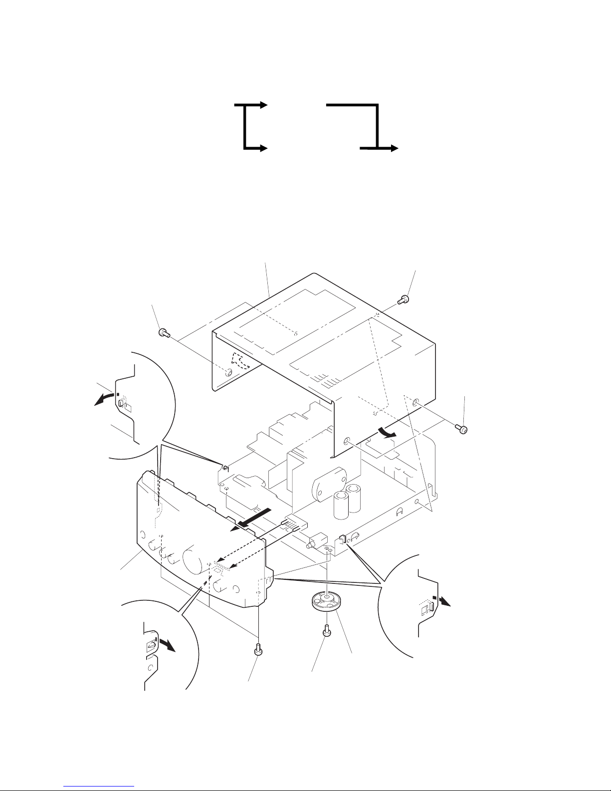
DISASSEMBLY
• This set can be disassembled in the order shown below.
CONNECTOR BOARD
(Page 7)
BACK PANEL
(Page 7)
MAIN BOARD
(Page 8)
CASE, FRONT PANEL ASS’Y
(Page 6)
1
screw (BVTT3 × 8)
2
two screws
(case 3 TP2)
2
two screws
(case 3 TP2)
3
case
4
two screws
(BVTP3
×
10)
5
two legs (F)
6
three screws
(BVTP3
×
10)
7
claw
7
two claws
7
two claws
8
front panel ass’y
CASE, FRONT PANEL ASS’Y
Note: Follow the disassembly procedure in the numerical order given.
– 7 –
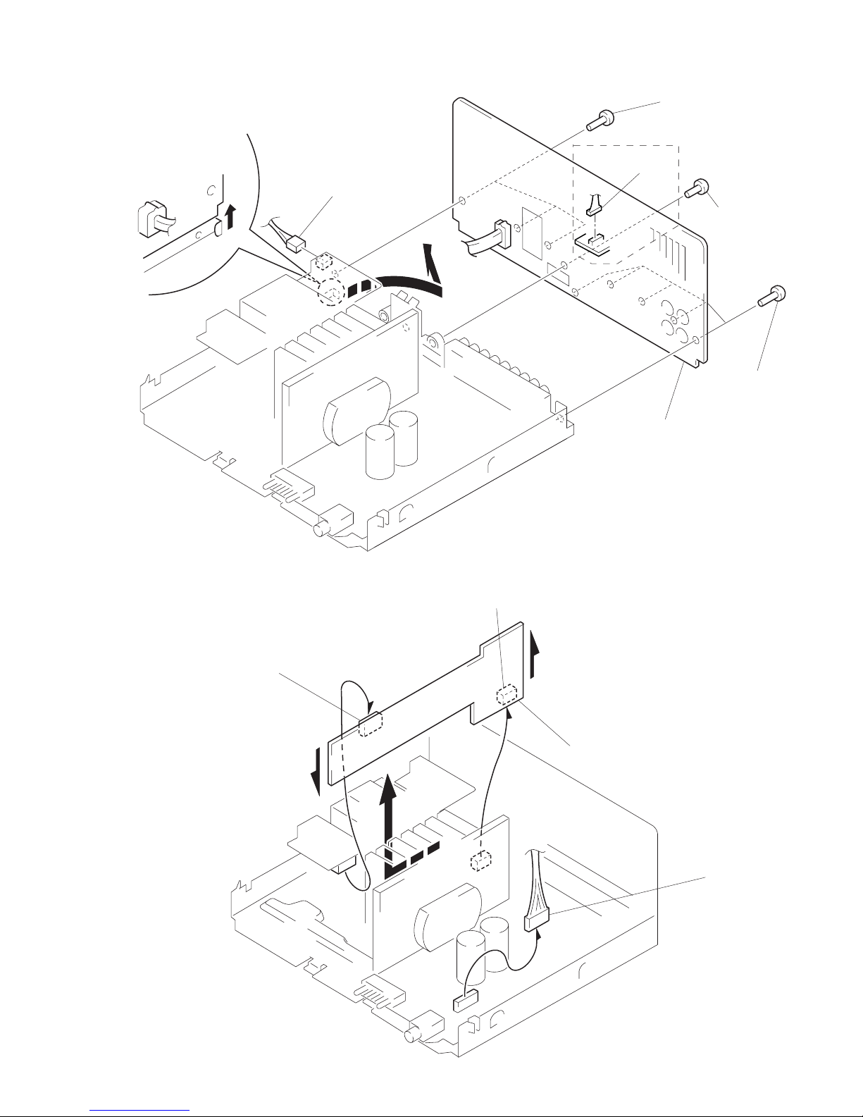
BACK PANEL
CONNECTOR BOARD
1
connector
(CN911)
2
connector
(CN504)
3
screw
(BVTP3
×
8)
3
three screws
(BVTP3
×
10)
3
five screws
(BVTP3
×
10)
4
claw
5
Remove the back panel to
direction of the arrow
A
.
A
EX77
1
connector
(CN501)
2
Remove the connector (CN553) to
direction of the arrow
A
.
3
Remove the connector (CN554) to
direction of the arrow
B
.
4
Remove the connector board to
direction of the arrow
C
.
A
B
C
– 8 –
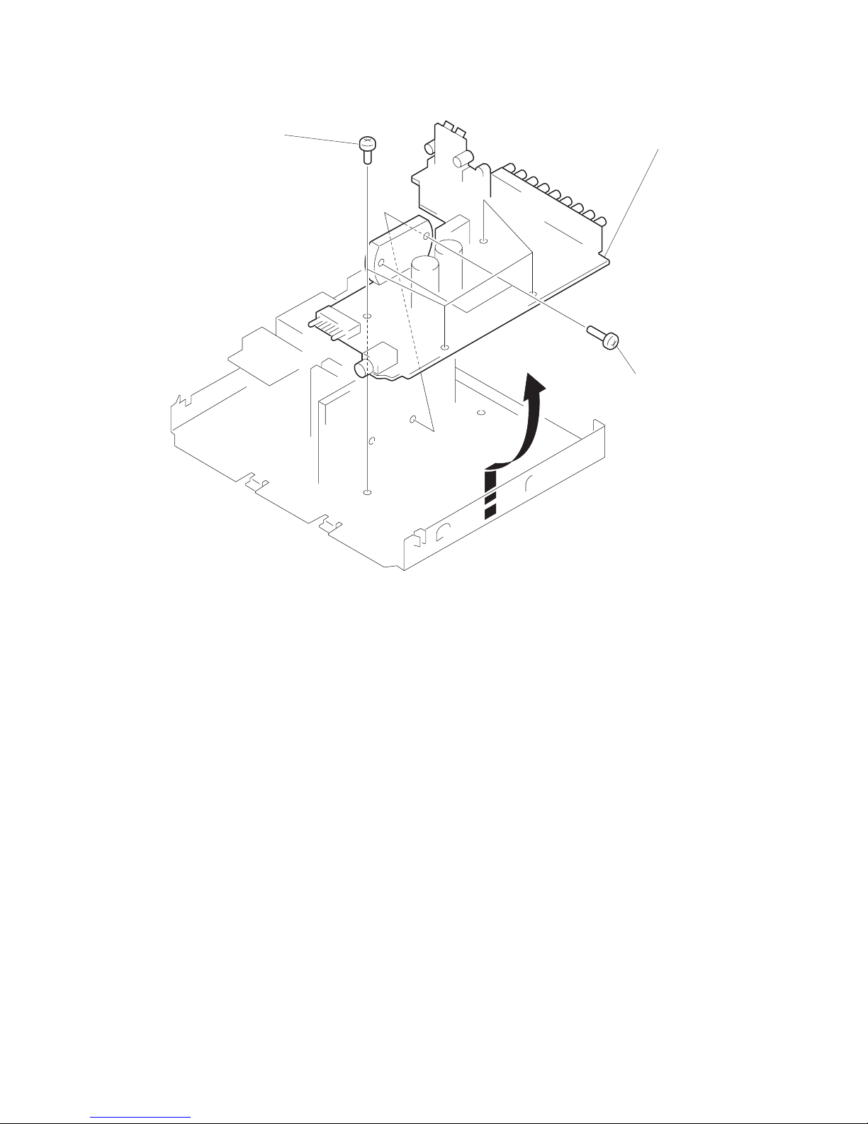
MAIN BOARD
1
two screws
(BVTP3
×
16)
2
four screws
(BVTT3
×
6)
3
Remove the MAIN board to
direction of the arrow.
 Loading...