

Page 1
Ster eo
Preamplifier
3-866-956-12(1)
Operating Instructions
Mode d’emploi
GB
FR
TA-E1
1999 by Sony Corporation
Page 2
WARNING
To prevent fire or shock
hazard, do not expose the
unit to rain or moisture.
Do not install the
appliance in a confined
space, such as a bookcase
or built-in cabinet.
For the customers in United States
This symbol is intended to alert the user to
the presence of uninsulated “dangerous
voltage” within the product’s enclosure
that may be of sufficient magnitude to
constitute a risk of electric shock to
persons.
This symbol is intended to alert the user to
the presence of important operating and
maintenance (servicing) instructions in the
literature accompanying the appliance.
For the customers in Canada
CAUTION
TO PREVENT ELECTRIC SHOCK, DO
NOT USE THIS POLARIZED AC PLUG
WITH AN EXTENSION CORD,
RECEPTACLE OR OTHER OUTLET
UNLESS THE BLADES CAN BE FULLY
INSERTED TO PREVENT BLADE
EXPOSURE.
Precautions
On safety
Should any solid object or liquid fall into
the cabinet, unplug the preamplifier and
have it checked by qualified personnel
before operating it any further.
On power sources
• Before operating the preamplifier, check
that the operating voltage is identical
with your local power supply. The
operating voltage is indicated on the
nameplate at the rear of the preamplifier.
• The unit is not disconnected from the AC
power source (mains) as long as it is
connected to the wall outlet, even if the
unit itself has been turned off.
• If you are not going to use the
preamplifier for a long time, be sure to
disconnect the preamplifier from the
wall outlet. To disconnect the AC power
cord, grasp the plug itself; never pull the
cord.
• AC power cord must be changed only at
the qualified service shop.
On placement
• Place the preamplifier in a location with
adequate ventilation to prevent heat
buildup and prolong the life of the
preamplifier.
• Do not place the preamplifier near heat
sources, or in a place subject to direct
sunlight, excessive dust or mechanical
shock.
• Do not place anything on top of the
cabinet that might block the ventilation
holes and cause malfunctions.
CAUTION
You are cautioned that any changes or
modification not expressly approved in
this manual could void your authority to
operate this equipment.
Owner’s Record
The model and serial numbers are located
on the rear of the unit. Record the serial
number in the space provided below.
Refer to them whenever you call upon
your Sony dealer regarding this product.
Model No. TA-E1
Serial No.
GB
2
On operation
Before connecting other components, be
sure to turn off and unplug the
preamplifier.
On cleaning
Clean the cabinet, panel and controls with
a soft cloth slightly moistened with a mild
detergent solution. Do not use any type of
abrasive pad, scouring powder or solvent
such as alcohol or benzine.
If you have any question or problem
concerning your preamplifier, please
consult your nearest Sony dealer.
Page 3

About This Manual
The instructions in this manual are for model TA-E1.
Check your model number by looking at the front panel.
In this manual, the European model is used for
illustration purposes unless stated otherwise. Any
difference in operation is clearly indicated in the text, for
example, “USA/Canada only.”
Conventions
• The instructions in this manual describe the controls on
the preamplifier.
• The following icon is used in this manual:
z Indicates hints and tips for making the task easier.
TABLE OF CONTENTS
Hooking Up the Components 4
Unpacking 4
Connections to a Power Amplifier (Unbalanced) 5
Connections to a Power Amplifier (Balanced) 6
Connections to Audio Components 7
Power Hookup 8
Location of Parts and Basic
Operations 10
Front Panel Parts Description 10
Rear Panel Parts Description 12
Other Operations 13
Recording 13
Additional Information 14
Troubleshooting 14
Specifications 15
GB
GB
3
Page 4

Hooking Up
Unpacking
the
Components
This chapter describes how to connect
an amplifier as well as various audio
components to the preamplifier. Be
sure to read the sections for the
components you have before you
actually connect them to the
preamplifier.
Check that you received the following items with the unit:
• Audio cord (1)
• AC power cord (1)
• AC power plug adapter (3 to 2 prong polarized type) (1)
(USA/Canada only)
Before you get started
• Turn off the power to all components before making
any connections.
• Do not connect the AC power cords until all of the
connections are completed.
• Be sure to make connections firmly to avoid hum and
noise.
• When connecting an audio cord, be sure to match the
color-coded pins to the appropriate jacks on the
components: white (left) to white; and red (right) to
red.
GB
4
Page 5
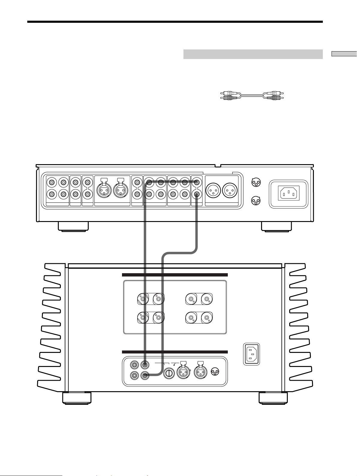
Power Amplifier Hookup (Unbalanced Connections)
Connect the preamplifier’s PRE OUT jacks to your power
amplifier’s UNBALANCED input jacks (Sony TA-N1,
etc.). For details, see the operating instructions supplied
with your power amplifier.
L
R
2R1
SACDCDLINE BALANCED LINE
L
DIRECT
OUT IN
TAPE2/MD
Required cords
Audio cords (1 cord is supplied)
When connecting a cord, be sure to match the color-coded pins to
the appropriate jacks on the components.
White (L) White (L)
Red (R) Red (R)
CONNECTION
ASSIGNMENT
1
2
3
1 :GROUND
2 :HOT ( + )
3 :COLD ( – )
1
3
1 :GROUND
2 :HOT ( + )
3 :COLD ( – )
2
OUT IN
TAPE1/DAT
PRE OUT
L
R
R
BALANCED OUT
L
Hooking Up the Components
TA-E1
TA-N1, etc.
SPEAKERS
+
L
RR –
+
–
–A–
–B–
L
+
–
+
IMPEDANCE USE 4~16Ω
A +
B USE 8~16Ω
INPUT
L
R
UNBALANCED
12
BALANCEDUNBALANCED
1
2
–
CONNECTION
ASSIGNMENT
2
1
3
1 : GROUND
2 : HOT(+)
BALANCEDINPUT SELECTOR
R
3 : COLD(–)
L
GB
5
Page 6
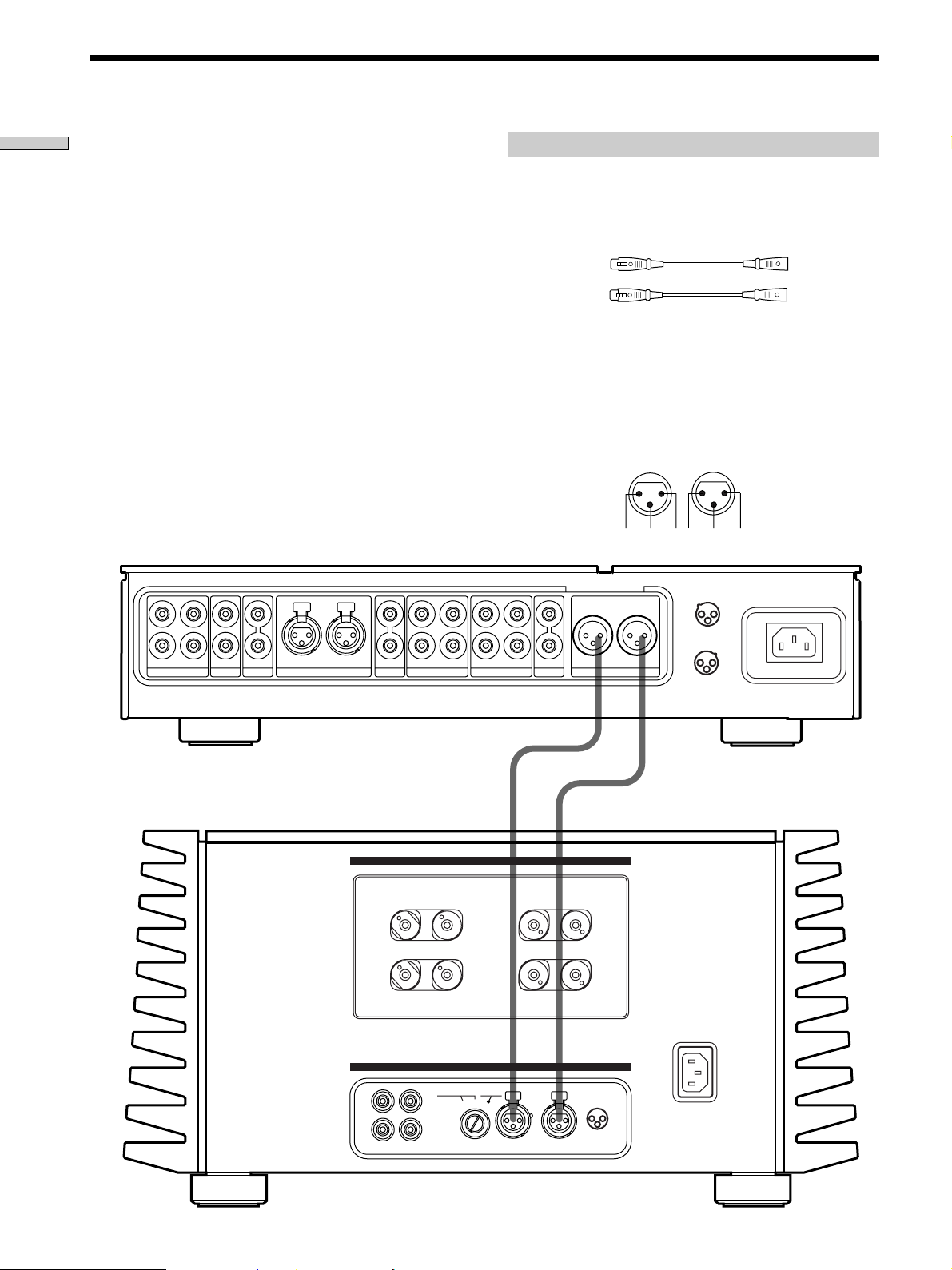
Power Amplifier Hookup (Balanced Connections)
IN OUT
2 3 1 1 3 2
Hooking Up the Components
Connect the preamplifier’s BALANCED OUT jacks to
your power amplifier’s BALANCED input jacks (Sony
TA-N1, etc.). For details, see the operating instructions
supplied with your power amplifier.
L
R
2 R1
SACDCDLINE BALANCED LINE
L OUT IN
DIRECT
OUT IN
TAPE2/MD
Required cords
Balanced cords (not supplied)
When connecting a cord, be sure to insert the plugs firmly in the
jacks. If the plugs are not connected firmly, noise may be
produced.
To the preamplifier To the power amplifier
(L) (L)
(R) (R)
Note
The pin assignment of the BALANCED output jacks on the
preamplifier is 1:GROUND, 2:HOT, and 3:COLD. When
connections are made to an amplifier with a pin assignment of
1:GROUND, 2:COLD, and 3:HOT, reverse the polarities (‘ and
’) of the speaker cables. For details, refer to the instructions
supplied with the preamplifier.
1: GROUND
2: HOT (+)
3: COLD (–)
CONNECTION
ASSIGNMENT
1
2
3
1 :GROUND
2 :HOT ( + )
3 :COLD ( – )
1
3
1 :GROUND
2 :HOT ( + )
3 :COLD ( – )
2
TAPE1/DAT
PRE OUT
L
R
R
BALANCED OUT
L
TA-E1
GB
6
TA-N1, etc.
SPEAKERS
+
L
RR –
+
–
–A–
–B–
L
+
–
+
IMPEDANCE USE 4~16Ω
A +
B USE 8~16Ω
INPUT
L
R
UNBALANCED
12
BALANCEDUNBALANCED
1
2
–
CONNECTION
ASSIGNMENT
2
1
3
1 : GROUND
2 : HOT(+)
3 : COLD(–)
L
R
BALANCEDINPUT SELECTOR
Page 7
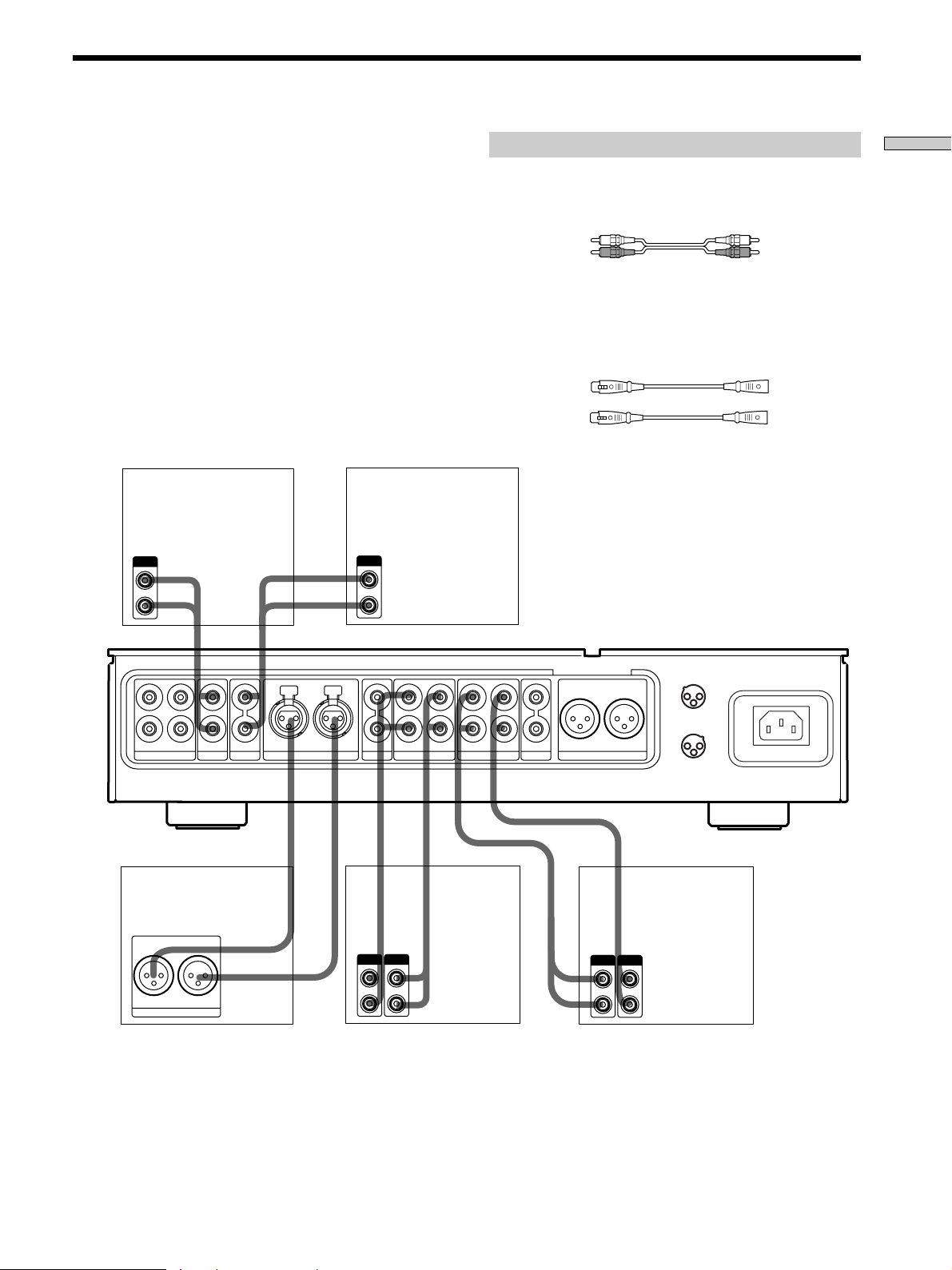
Audio Component Hookups
Connect the analog line outputs of your audio
components (SACD player, CD player, MD deck, DAT
deck, tape deck, etc.) to the analog line jacks on this unit.
If you have a component with balanced output capability,
that component can be connected to the BALANCED
LINE jacks on this unit.
Note
When making connections to a CD player (etc.) that has both
balanced and unbalanced output capability, make connections to
either the CD input jacks or to the BALANCED LINE jacks, but
not both. Making connections to both inputs may lessen the
quality of the audio output, or audio may not be output at all.
CD Player
Super Audio CD
Player
OUTPUT
L
R
OUTPUT
L
R
Required cords
Audio cords (not supplied)
When connecting a cord, be sure to match the color-coded pins to
the appropriate jacks on the components.
White (L) White (L)
Red (R) Red (R)
Balanced cords (not supplied)
When connecting a balanced cord, be sure to insert the plugs
firmly in the jacks. If the plugs are not connected firmly, noise
may be produced.
To the source component To the preamplifier
(L) (L)
(R) (R)
Hooking Up the Components
L
R
2R1
Audio component
with balanced
output jacks
R
BALANCED OUT
SACDCDLINE BALANCED LINE
L
TA-E1
CONNECTION
ASSIGNMENT
1
L
R
DIRECT
ç
IN
OUT IN
TAPE2/MD
ç
OUT
OUT IN
TAPE1/DAT
IN
ç
PRE OUT
R
OUT
ç
L
BALANCED OUT
L
Tape deck,
MD deck ,
(etc.)
OUTPUT
INPUT
L
R
INPUT
OUTPUT
2
1 :GROUND
2 :HOT ( + )
3 :COLD ( – )
1
1 :GROUND
2 :HOT ( + )
3 :COLD ( – )
Tape deck,
DAT deck ,
(etc.)
L
R
3
2
3
GB
7
Page 8
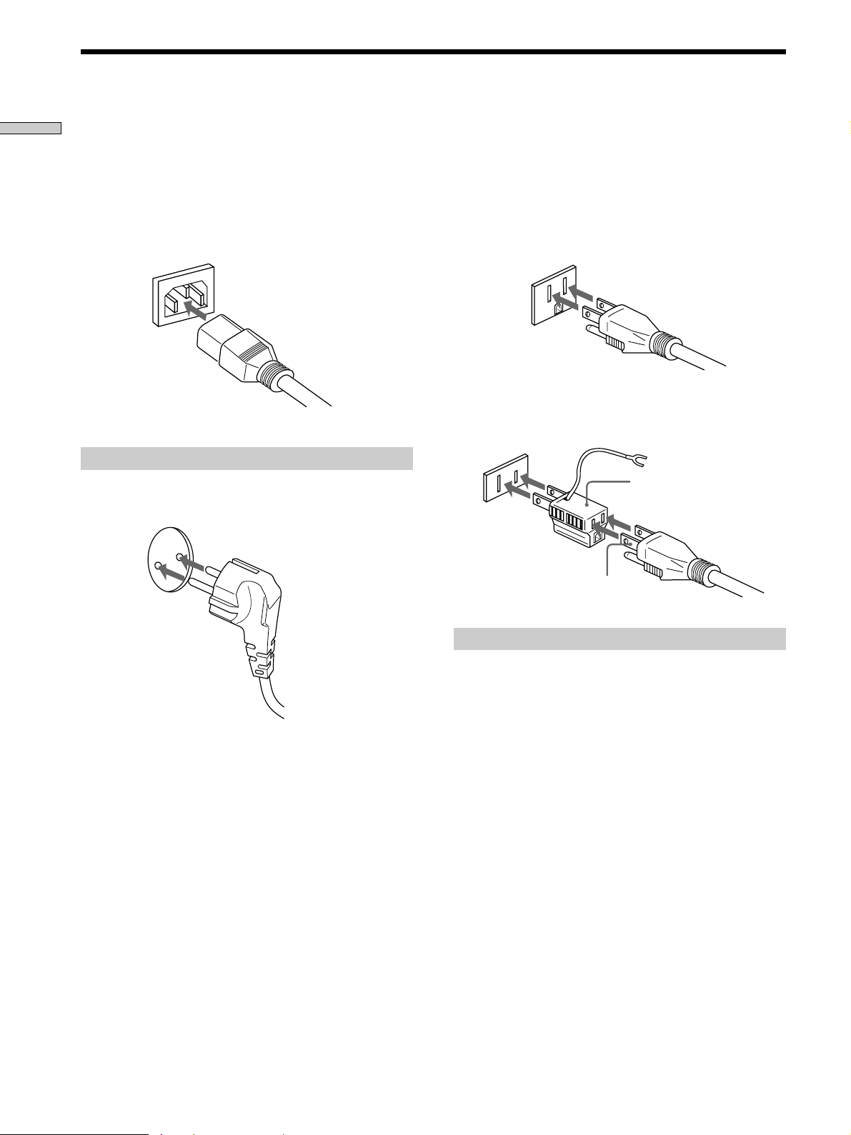
Power Hookup
Hooking Up the Components
Before connecting the AC power cord of this preamplifier
to a wall outlet:
• Make sure that the power switch on the preamplifier is
in the off position.
Connect the supplied power cord to the AC IN terminal
on this unit.
Connecting to the power outlet
(European model only)
Connect the supplied power cord to a wall outlet.
(USA/Canadian model only)
The supplied power cord has a 3-pronged grounded plug.
If you are using a 3-pronged grounded outlet, the plug
can be inserted directly into the outlet. However, if the
socket is a 2-pronged grounded outlet, use the supplied
AC power plug adapter or a commercially available AC
power plug adapter.
3-pronged grounded outlet
2-pronged polarized outlet
• When using a grounded outlet (the inlets are different sizes)
Use the supplied AC power plug adapter.
3 to 2 prong polarized
AC power plug adapter
N pole
If noise (hum) is produced
Noise may be caused by an electrical potential difference on the
ground circuit*. In this case, use the supplied AC power plug
adapter and be careful not to connect the ground lead to
anything.
* Although the ground of the domestic outlet is normally a safety
ground, a slight electrical potential difference may be
produced, depending on the outlet. Therefore, use of the
supplied 3-pronged power cord may lessen the quality of the
audio signal or may produce humming noise.
Note
We recommend that you connect this unit directly to a wall
outlet. If you must use a multi-outlet tap, or extension cord, be
sure to use one capable of handling high current (at least 10 A) or
one designed for office use.
GB
8
Page 9

Hooking Up the Components
GB
9
Page 10

Location of Parts and Basic Operations
This chapter provides information
about the locations and functions of
the buttons and controls on the front
and the various jacks on the rear
panel. It also explains basic
operations.
Front Panel Parts Description
1 U (power) switch
Press to turn the preamplifier on and off.
• Before you turn on the preamplifier, make sure that you
have turned the VOLUME control to the leftmost position
to avoid damaging your speakers.
2 Power indicator
Lights red for 12 seconds when preamplifier is turned
on, and then lights green.
3 INPUT SELECTOR control
Turn to select the component you want to use.
To select Turn to light
DAT deck, tape deck 1 DAT/TAPE 1
MD deck MD/TAPE 2
BALANCED LINE BALANCED LINE
SACD player SACD
CD player CD
LINE 1 LINE 1
LINE 2 LINE 2
After selecting the component, turn on the component
you selected and play the program source.
10
GB
Page 11

2 3 74 65
INPUT SELECTOR
BALANCED LINE
MD/TAPE 2
DAT/TAPE 1
SACD
CD
LINE 1
LINE 2
TAPE MONITOR
TAPE 1
TAPE 2
DIRECT
Location of Parts and Basic Operations
VOLUME
5
4
3
2
6
7
8
1
4 TAPE MONITOR button
Press to turn the tape monitor on and off. The
indicator lights when the tape monitor is on and goes
out when the tape monitor is turned off.
5 TAPE MONITOR input select button
When the TAPE MONITOR (4) is on, press to select
the input from the TAPE 1 or TAPE 2 input jacks. The
indicator lights to show which input is selected.
6 DIRECT button
Press to select the input connected to the DIRECT
input jacks. The indicator lights, and the source
component connected to the DIRECT input jacks takes
priority over the source component selected with the
INPUT SELECTOR control (3).
Press the DIRECT button again to return to the source
selected with the INPUT SELECTOR control.
1
0
9
10
7 VOLUME control
After turning on the component you selected, turn to
adjust the volume.
11
GB
Page 12

Rear Panel Parts Description
1
Location of Parts and Basic Operations
L
R
2R1
1 LINE 1/2 input jacks
Connect to the analog audio output jacks of your
audio components (see page 7).
2 CD input jacks
Connect to the audio output jacks of your CD player
(see page 7).
3 SACD input jacks
Connect to the audio output jacks of your SACD
player (see page 7).
4 BALANCED LINE input jacks
Connect to the BALANCED OUT jacks of an audio
component that is capable of balanced output (XLR
type) (see page 7).
5 DIRECT input jacks
Connect to the analog audio output jacks of your
audio components. When a component is connected to
these jacks, pressing the DIRECT button to select the
component causes the indicator on the front panel to
light.
When the DIRECT button is pressed, the component
connected to these jacks takes priority over the
component selected with the INPUT SELECTOR
control.
SACDCDLINE BALANCED LINE
5 6 7 8 9432
L
R
DIRECT
OUT IN
TAPE2/MD
OUT IN
TAPE1/DAT
PRE OUT
R
BALANCED OUT
L
L
*
CONNECTION
ASSIGNMENT
1
2
3
1 :GROUND
2 :HOT ( + )
3 :COLD ( – )
2
1
3
1 :GROUND
2 :HOT ( + )
3 :COLD ( – )
**
6 TAPE 2/MD, TAPE 1/DAT IN/OUT jacks
Use to connect the input and output jacks of your DAT
deck, MD deck, tape player (etc.) (page 7).
7 PRE OUT jacks
Connect to your power amplifier(s) (see page 5).
8 BALANCED OUT jacks
Connect to your power amplifier(s) using balanced
cords (see page 6).
* : Displays the pin polarity of the BALANCED LINE jacks.
** : Displays the pin polarity of the BALANCED OUT jacks.
9 AC IN terminal
Connect the supplied power cord to the AC IN
terminal and then to the wall outlet to supply power
to the unit (see page 8).
12
GB
Page 13

Other
Recording
Operations
This chapter describes the operation
necessary to record the output of the
components connected to this unit on
your DAT deck, MD deck, or tape
deck (etc.).
Your preamplifier makes it easy to record to and from the
components connected to it. You don’t have to connect
the playback and recording components directly to each
other: once you select a program source on the
preamplifier, you can record and edit as you normally
would using the controls on each component.
Before you begin, make sure you’ve connected all
components properly.
Recording on an audio tape or MiniDisc
You can record on a cassette tape or MiniDisc using the
preamplifier. See the instruction manual of your tape deck
or MD deck if you need help.
1 Turn INPUT SELECTOR to select the component to
be recorded.
For example, select CD.
2 Prepare the component for playing.
For example, insert a CD into the CD player.
3 Insert a blank tape or MD into the recording deck
and adjust the recording level, if necessary.
Other Operations
4 Start recording on the recording deck, then start
playback on the playback component.
z You can check what is being recorded (tape monitor)
When using a 3-head tape deck, it is possible to check the signal
that is actually being recorded. For example, if the tape deck
connected to the DAT/TAPE 1 input jacks is being used to make
a recording, press TAPE MONITOR to turn the tape monitor on
(the indicator lights) and then TAPE 1/TAPE 2 until the indicator
above TAPE 1 lights.
Notes
• You cannot record a digital audio signal using a component
connected to the analog TAPE 1/DAT OUT jacks or TAPE 2/
MD OUT jacks. To record a digital audio signal, connect the
digital output of the source component directly to the digital
input of the recording deck.
• Sound adjustments do not affect the signal output from the
TAPE1/DAT OUT or TAPE 2/MD OUT jacks.
13
GB
Page 14

Additional
Troubleshooting
Information
If you experience any of the following difficulties while
using the preamplifier, use this troubleshooting guide to
help you remedy the problem. Should any problem
persist, consult your nearest Sony dealer.
There’s no sound or only a very low-level sound
is heard.
/ Check that all components are connected securely.
/ Make sure that you’ve selected the correct
component on the preamplifier.
The left and right sounds are unbalanced or
reversed.
/ Check that all components are connected correctly
and securely.
Severe hum or noise is heard.
/ Check that all components are connected securely.
/ Check that the connecting cords are away from a
transformer or motor, and at least 3 meters (10 feet)
away from a TV set or fluorescent light.
/ Move your TV away from the audio components.
/ The plugs and jacks are dirty. Wipe them with a
cloth slightly moistened with alcohol.
Recording cannot be done.
/ Check that the components are connected correctly.
/ Select the source component by rotating the
INPUT SELECTOR control.
14
GB
Page 15

Specifications
Audio section
Harmonic distortion
Less than 0.005%
(at 2 V, THD)
Frequency response
5 Hz ~ 300 kHz
(0 ~ –1 dB)
Signal-to-noise ratio
More than 115 dB
(Input shorted, A-Fil)
Inputs
Input Sensitivity Impedance
LINE 1 250 mV 20 kΩ
LINE 2 250 mV 20 kΩ
CD 250 mV 20 kΩ
SACD 250 mV 20 kΩ
BALANCED
LINE
DAT/TAPE 1 250 mV 20 kΩ
MD/TAPE 2 250 mV 20 kΩ
250 mV 40 kΩ
General
Power requirements
USA and Canadian
models :
120 V AC, 60Hz
European models :
230 V AC, 50/60Hz
Power consumption
18 W
Dimensions 430 × 108 × 445 mm
Mass (Approx.)
21.5 kg (47 lb. 06 oz.)
Supplied accessories
See page 4.
Design and specifications are subject
to change without notice.
1
(17 × 4
/4 × 171/2 in.)
including projecting
parts and controls
Additional Information
Outputs
Output Voltage Impedance
PRE OUT 2 V 47 Ω
BALANCED 2 V 220 Ω
OUT
15
GB
Page 16

AVERTISSEMENT
Précautions
Afin d’éviter tout risque
d’incendie ou
d’électrocution, ne pas
exposer cet appareil à la
pluie ou à l’humidité.
N’installez pas l’appareil
dans un espace confiné
comme dans une
bibliothèque ou un
meuble encastré.
A l’attention de la clientèle canadienne
ATTENTION:
POUR PREVENIR LES CHOCS
ELECTRIQUES, NE PAS UTILISER CETTE
FICHE POLARISEE AVEC UN
PROLONGATEUR, UNE PRISE DE
COURANT OU UNE AUTRE SORTIE DE
COURANT, SAUF SI LES LAMES
PEUVENT ETRE INSEREES A FOND
SANS EN LAISSER AUCUNE PARTIE A
DECOUVERT.
Sécurité
Si un solide ou un liquide tombait dans le
préamplificateur, débranchez-le et faites-le
vérifier par un technicien qualifié avant de
le remettre en marche.
Sources d’alimentation
• Avant de mettre le préamplificateur en
service, vérifiez que sa tension de
fonctionnement correspond à celle du
secteur local. La tension de
fonctionnement est indiquée sur la
plaque signalétique à l’arrière du
préamplificateur.
• Le préamplificateur n’est pas déconnecté
de la source d’alimentation secteur tant
qu’il reste branché sur la prise murale
(secteur), même s’il a été mis hors
tension.
• Débranchez le préamplificateur de la
prise murale si vous prévoyez de ne pas
l’utiliser pendant longtemps. Pour
débrancher le cordon secteur, tirez sur la
fiche. Ne tirez jamais sur le cordon.
• Si le cordon d’alimentation secteur a
besoin d’être changé, faites-le changer
par un technicien compétent
uniquement.
Installation
• Installez le préamplificateur dans un
endroit suffisamment aéré afin d’éviter
une surchauffe interne et pour prolonger
la durée de vie du préamplificateur.
• Ne pas installer le préamplificateur près
de sources de chaleur ou dans un endroit
exposé directement au soleil, à la
poussière ou à des chocs mécaniques.
• Ne poser aucun objet sur le coffret qui
pourrait obstruer les ailettes de
ventilation et provoquer un
dysfonctionnement.
Fonctionnement
Avant de brancher d’autres appareils,
veillez à mettre le préamplificateur hors
tension et à le débrancher.
Nettoyage
Nettoyez le coffret, le panneau et les
commandes avec un chiffon doux,
légèrement imbibé d’une solution
détergente douce. Ne pas utiliser de
tampon ou de poudre à récurer ou de
solvant, comme de l’alcool ou de la
benzine.
Pour toute question ou problème au
sujet du préamplificateur, veuillez
contacter votre revendeur Sony agréé.
FR
2
Page 17

Au sujet de ce mode
d’emploi
TABLE DES MATIÈRES
Les instructions de ce mode d’emploi couvrent le modèle
TA-E1. Vérifiez le numéro de votre modèle sur le panneau
avant. Dans ce manuel, les illustrations représentent le
modèle européen, sauf mention contraire. Toute différence
de fonctionnement est clairement indiquée dans le texte,
par exemple, “Etats-Unis/Canada seulement”.
Conventions
• Dans les instructions de ce manuel, les commandes
décrites sont celles du préamplificateur.
• L’icône suivante est utilisée dans ce mode d’emploi :
z Indique des conseils et suggestions pouvant faciliter
certaines opérations.
Raccordement des appareils 4
Déballage 4
Raccordement d’unamplificateur de puissance
(liaisons asymétriques) 5
Raccordement d’unamplificateur de puissance
(liaisons symétriques) 6
Raccordement d’un appareil audio 7
Raccordement de l’alimentation 8
Nomenclature et opérations
élémentaires 10
Description des éléments du panneau avant 10
Description des éléments du panneau arrière 12
Autres opérations 13
Enregistrement 13
FR
Informations complémentaires 14
Guide de dépannage 14
Spécifications 15
FR
3
Page 18

Raccordement
Déballage
des appareils
Ce chapitre explique comment
raccorder un amplificateur et d’autres
appareils audio au préamplificateur.
Veuillez lire attentivement les
paragraphes concernant les appareils
que vous raccordez au
préamplificateur.
Vérifiez si les accessoires suivants se trouvent bien dans le
carton d’emballage.
• Cordon de liaison audio (1)
• Cordon d’alimentation secteur (1)
• Adaptateur de prise d’alimentation secteur (type
polarisé 3 à 2 broches) (1) (Etats-Unis/Canada
seulement)
Avant de commencer
• Mettez tous les appareils hors tension avant d’effectuer
les liaisons.
• Ne raccordez les cordons d’alimentation secteur que
lorsque toutes les liaisons sont terminées.
• Enfoncez les fiches à fond dans les prises pour éviter
tout bourdonnement et bruit.
• Lorsque vous raccordez un cordon audio, branchez les
fiches sur les prises de même couleur : blanc (gauche) à
blanc et rouge (droit) à rouge.
FR
4
Page 19

Raccordement d’unamplificateur de puissance (liaisons asymétriques)
Reliez les prises PRE OUT du préamplificateur aux prises
d’entrée UNBALANCED de l’amplificateur de puissance
(Sony TA-N1, etc.). Pour les détails, voir le mode d’emploi
fourni avec l’amplificateur de puissance.
L
R
2R1
SACDCDLINE BALANCED LINE
L
DIRECT
OUT IN
TAPE2/MD
Cordons nécessaires
Cordons audio (1 cordon est fourni)
Lorsque vous raccordez un cordon, veillez à brancher les fiches
sur les prises appropriées sur les appareils.
Blanc (gauche) Blanc (gauche)
Rouge (droite) Rouge (droite)
CONNECTION
ASSIGNMENT
1
2
3
1 :GROUND
2 :HOT ( + )
3 :COLD ( – )
1
3
1 :GROUND
2 :HOT ( + )
3 :COLD ( – )
2
OUT IN
TAPE1/DAT
PRE OUT
L
R
R
BALANCED OUT
L
Raccordement des appareils
TA-E1
TA-N1, etc.
SPEAKERS
+
L
RR –
+
–
–A–
–B–
L
+
–
+
IMPEDANCE USE 4~16Ω
A +
B USE 8~16Ω
INPUT
L
R
UNBALANCED
12
BALANCEDUNBALANCED
1
2
–
CONNECTION
ASSIGNMENT
2
1
3
1 : GROUND
2 : HOT(+)
BALANCEDINPUT SELECTOR
R
3 : COLD(–)
L
FR
5
Page 20

Raccordement d’unamplificateur de puissance (liaisons symétriques)
IN OUT
2 3 1 1 3 2
Raccordement des appareils
Reliez les prises BALANCED OUT du préamplificateur
aux prises d’entrée BALANCED de l’amplificateur de
puissance (Sony TA-N1, etc.). Pour les détails, voir le
mode d’emploi fourni avec l’amplificateur de puissance.
L
R
2 R1
SACDCDLINE BALANCED LINE
L OUT IN
DIRECT
OUT IN
TAPE2/MD
Cordons nécessaires
Cordons symétriques (non fournis)
Lorsque vous raccordez un cordon, veillez à enfoncer les fiches à
fond dans les prises. Si les fiches ne sont pas bien branchées, la
connexion produira du bruit.
Au préamplificateur A l’amplificateur de puissance
(gauche) (gauche)
(droite) (droite)
Remarque
L’affectation des broches des prises de sortie BALANCED sur le
préamplificateur est 1 : GROUND, 2 : HOT et 3 : COLD. Si vous
raccordez le préamplificateur à un amplificateur dont
l’affectation des fiches est 1 : GROUND, 2 : COLD et 3 : HOT,
inversez la polarité (‘ et ’) des cordons d’enceintes. Pour les
détails, reportez-vous au mode d’emploi du préamplificateur.
1: GROUND
2: HOT (+)
3: COLD (–)
CONNECTION
ASSIGNMENT
1
2
3
1 :GROUND
2 :HOT ( + )
3 :COLD ( – )
1
3
1 :GROUND
2 :HOT ( + )
3 :COLD ( – )
2
TAPE1/DAT
PRE OUT
L
R
R
BALANCED OUT
L
TA-E1
FR
6
TA-N1, etc.
SPEAKERS
+
L
RR –
+
–
–A–
–B–
L
+
–
+
IMPEDANCE USE 4~16Ω
A +
B USE 8~16Ω
INPUT
L
R
UNBALANCED
12
BALANCEDUNBALANCED
1
2
–
CONNECTION
ASSIGNMENT
2
1
3
1 : GROUND
2 : HOT(+)
3 : COLD(–)
L
R
BALANCEDINPUT SELECTOR
Page 21

Raccordement d’un appareil audio
Raccordez les sorties de ligne analogiques de vos
appareils audio (lecteur SACD, lecteur CD, platine MD,
platine DAT, platine à cassette, etc.) aux prises de ligne
analogiques de l’appareil. Si votre appareil est pourvu de
sorties symétriques, il pourra être raccordé aux prises
BALANCED LINE du préamplificateur.
Remarque
Lorsque vous reliez un lecteur CD (etc.) pourvu de prises de
sortie symétriques et asymétriques, effectuez les liaisons soit aux
prises d’entrée CD soit aux prises BALANCED LINE mais pas
aux deux. Si vous raccordez les deux prises, le son risque d’être
de moins bonne qualité ou totalement absent.
Lecteur CD
Lecteur Super
Audio CD
OUTPUT
L
R
OUTPUT
L
R
Cordons nécessaires
Cordons audio (non fournis)
Lorsque vous raccordez un cordon, veillez à brancher les fiches
sur les prises appropriées sur les appareils.
Blanc (gauche) Blanc (gauche)
Rouge (droite) Rouge (droite)
Cordons symétriques (non fournis)
Lorsque vous raccordez un cordon symétrique, veillez à enfoncer
les fiches à fond dans les prises. Si les fiches ne sont pas bien
branchées, la connexion produira du bruit.
A l’appareil source Au préamplificateur
(gauche) (gauche)
(droite) (droite)
Raccordement des appareils
L
R
2R1
Appareil audio
avec prises de
sortie symétrique
R
BALANCED OUT
SACDCDLINE BALANCED LINE
L
TA-E1
CONNECTION
ASSIGNMENT
1
Platine à
cassette,
Platine
DAT, etc.
L
R
2
3
1 :GROUND
2 :HOT ( + )
3 :COLD ( – )
1
3
1 :GROUND
2 :HOT ( + )
3 :COLD ( – )
2
L
R
DIRECT
ç
IN
OUT IN
TAPE2/MD
ç
OUT
OUT IN
TAPE1/DAT
IN
ç
PRE OUT
R
OUT
ç
L
BALANCED OUT
L
Platine à
cassette,
Platine
DAT, etc.
OUTPUT
INPUT
L
R
INPUT
OUTPUT
FR
7
Page 22

Raccordement de l’alimentation
Raccordement des appareils
Avant de brancher le cordon d’alimentation secteur du
préamplificateur sur une prise murale :
• Le préamplificateur doit être éteint par l’interrupteur
d’alimentation.
Branchez le cordon d’alimentation secteur fourni sur la
prise AC IN de cet appareil.
Branchement sur la prise d’alimentation
secteur
(Modèle européen seulement)
Branchez le cordon d’alimentation secteur fourni sur une
prise murale.
(Modèle pour les Etats-Unis/Canada seulement)
Le cordon d’alimentation secteur fourni est pourvu d’une
fiche à 3 broches dont une de terre. Si vous utilisez une
prise à 3 broches, vous pourrez brancher directement la
fiche dans la prise, sinon si la prise n’a que 2 broches vous
devrez utiliser l’adaptateur de fiche d’alimentation
secteur fourni ou un adaptateur de fiche en vente dans le
commerce.
Prise à 3 broches dont une de terre
Prise polarisée à 2 broches
• Si vous utilisez une prise à conducteur de terre (les orifices sont
de différentes tailles)
Utilisez l’adaptateur de fiche d’alimentation secteur fourni.
Adaptateur de fiche
d’alimentation secteur 3
à 2 broches
En cas de bruit (bourdonnement)
Du bruit peut être causé par une différence de potentiel électrique
dans le circuit de terre*. Dans ce cas, utilisez l’adaptateur de fiche
d’alimentation secteur fourni et veillez à ne pas brancher le
conducteur de terre.
* Bien que la terre des prises d’alimentation domestiques soit
normalement sûre, une légère différence de potentiel électrique
peut se produire sur certaines prises. Dans ce cas, l’utilisation
du cordon et de la fiche à 3 broches peut réduire la qualité du
signal audio et produire un bourdonnement.
Remarque
Il est conseillé de brancher directement l’appareil sur une prise
murale. Si vous utilisez un prise multifiches ou un cordon
rallonge, assurez-vous qu’il peut supporter un courant élevé (au
moins 10 A) ou utilisez-en un conçu pour l’équipement
bureautique.
FR
8
Page 23

Raccordement des appareils
FR
9
Page 24

Nomenclature et opérations élémentaires
Ce chapitre décrit l’emplacement et
les fonctions des touches et
commandes situées en façade et les
diverses prises à l’arrière de
l’appareil. Il décrit aussi les opérations
élémentaires.
Description des éléments du panneau avant
1 Interrupteur d’alimentation U
Met le préamplificateur sous ou hors service.
• Avant de mettre le préamplificateur en service, assurezvous que la commande VOLUME est sur la position
extrême gauche pour éviter d’endommager les hautparleurs.
2 Témoin d’alimentation
S’allume en rouge pendant 12 secondes lorsque le
préamplificateur est en service puis il devient vert.
3 Commande INPUT SELECTOR
Sert à sélectionner l’appareil que vous voulez utiliser.
Pour sélectionner
Platine DAT, platine à
cassette 1
Platine MD
BALANCED LINE
Lecteur SACD
Lecteur CD
LINE 1
LINE 2
Après avoir sélectionné l’appareil, mettez-le en service
et écoutez la source de programme.
Tournez pour allumer le témoin
DAT/TAPE 1
MD/TAPE 2
BALANCED LINE
SACD
CD
LINE 1
LINE 2
10
FR
Page 25

2 3 74 65
INPUT SELECTOR
BALANCED LINE
MD/TAPE 2
DAT/TAPE 1
SACD
CD
LINE 1
LINE 2
TAPE MONITOR
TAPE 1
TAPE 2
DIRECT
Nomenclature et opérations élémentaires
VOLUME
5
4
3
2
6
7
8
1
4 Touche TAPE MONITOR
Sert à mettre le contrôle du son en ou hors service. Le
témoin s’allume lorsque la fonction est en service et
s’éteint lorsqu’elle est hors service.
5 Sélecteur d’entrée TAPE MONITOR
Lorsque la touche TAPE MONITOR (4) a été activée,
sert à sélectionner l’entrée TAPE 1 ou TAPE 2. Le
témoin s’allume pour indiquer l’entrée sélectionnée.
6 Touche d’entrée DIRECT
Sert à sélectionner l’entrée raccordée aux prises
d’entrée DIRECT. Le témoin s’allume et l’appareil
source raccordé aux prises d’entrée DIRECT a priorité
sur l’appareil source sélectionné avec la commande
INPUT SELECTOR (3).
Pour revenir à l’entrée sélectionnée avec la commande
INPUT SLECTOR, appuyez une nouvelle fois sur la
touche DIRECT.
1
0
9
10
7 Commande VOLUME
Sert à régler le volume après la mise en service de
l’appareil sélectionné.
11
FR
Page 26

Description des éléments du panneau arrière
Nomenclature et opérations élémentaires
5 6 7 8 9432
L
DIRECT
L
R
1
2R1
SACDCDLINE BALANCED LINE
1 Prises d’entrée LINE 1/2
Elles doivent être reliées aux prises de sortie audio
analogique de vos appareils audio (voir page 7).
2 Prises d’entrée CD
Elles doivent être reliées aux prises de sortie audio de
votre lecteur CD (voir page 7).
3 Prises d’entrée SACD
Elles doivent être reliées aux prises de sortie audio de
votre lecteur SACD (voir page 7).
4 Prises d’entrée BALANCED LINE
Elles doivent être reliées aux prises BALANCED OUT
d’un appareil audio pourvu d’une sortie symétrique
(type XLR) (voir page 7).
5 Prises d’entrée DIRECT
Elles doivent être reliées aux prises de sortie audio
analogique de vos appareils audio. Lorsqu’un appareil
est relié à ces prises, sélectionnez-le en appuyant sur la
touche DIRECT. Le témoin s’allumera sur le panneau
avant.
Lorsque la touche DIRECT est activée, l’appareil
raccordé à ces prises a priorité sur l’appareil
sélectionné par la commande INPUT SELECTOR.
OUT IN
TAPE2/MD
*
CONNECTION
ASSIGNMENT
1
2
3
1 :GROUND
2 :HOT ( + )
3 :COLD ( – )
2
1
3
1 :GROUND
2 :HOT ( + )
3 :COLD ( – )
OUT IN
TAPE1/DAT
PRE OUT
L
R
R
BALANCED OUT
L
**
6 Prises d’entrée/sortie TAPE 2/MD, TAPE 1/DAT IN/
OUT
Elles doivent être reliées aux prises de sortie et
d’entrée de votre platine DAT, platine MD et platine à
cassette (etc.) (page 7).
7 Prises PRE OUT
Elles doivent être reliées à l’amplificateur (ou aux
amplificateurs) de puissance (voir page 5).
8 Prises BALANCED OUT
Elles doivent reliées à l’amplificateur (ou aux
amplificateurs) de puissance à l’aide de cordons
symétriques (voir page 6).
* : Indique la polarité des broches des prises BALANCED
LINE.
** : Indique la polarité des broches des prises BALANCED
OUT.
9 Prise AC IN
Elle doit être reliée à une prise murale par le cordon
d’alimentation fourni pour alimenter l’appareil (voir
page 8). Branchez le cordon d’abord sur la prise AC IN
puis sur la prise murale.
12
FR
Page 27

Autres
Enregistrement
opérations
Ce chapitre explique comment
enregistrer sur une platine DAT, une
platine MD ou une platine à cassette,
(etc.) le signal fourni par l’appareil
raccordé au préamplificateur.
Le préamplificateur facilite l’enregistrement vers et
depuis les appareils qui lui sont raccordés. Vous n’avez
pas besoin de relier les appareils de lecture et
d’enregistrement entre eux : il suffit de sélectionner la
source sur le préamplificateur pour faire des
enregistrements et des montages comme vous le feriez si
vous utilisiez les commandes de chaque appareil.
Avant de commencer, assurez-vous que tous les appareils
sont raccordés correctement.
Enregistrement sur une cassette audio ou
un minidisque
Vous pouvez enregistrer sur une cassette ou un
minidisque depuis le préamplificateur. Reportez-vous au
mode d’emploi de la platine à cassette ou de la platine
MD pour les détails.
1 Tournez INPUT SELECTOR pour sélectionner
l’appareil à enregistrer.
Par exemple, sélectionnez CD.
2 Préparez l’appareil pour la lecture.
Par exemple, insérez un CD dans le lecteur CD.
Autres opérations
3 Insérez une cassette ou un MD vierge dans
l’enregistreur et ajustez le niveau
d’enregistrement, si nécessaire.
4 Commencez l’enregistrement sur l’enregistreur et
la lecture sur le lecteur.
z Vous pouvez écouter l’enregistrement (contrôle du son)
Si vous utilisez une platine à cassette à 3 têtes, vous pourrez
contrôler le signal enregistré. Par exemple, si la platine à cassette
raccordée aux prises d’entrée DAT/TAPE 1 sert pour
l’enregistrement, appuyez sur TAPE MONITOR pour mettre la
fonction de contrôle en service (le témoin s’allume) puis sur
TAPE 1/TAPE 2 jusqu’à ce que le témoin au-dessus de TAPE 1
s’allume.
Remarques
• Vous ne pouvez pas enregistrer un signal audionumérique sur
un appareil raccordé aux prises analogiques TAPE 1/DAT OUT
ou TAPE 2/MD OUT. Pour enregistrer un signal
audionumérique, raccordez la sortie numérique de l’appareil
source directement à l’entrée numérique de l’enregistreur.
• Les réglages du son n’affectent pas le signal transmis aux prises
TAPE 1/DAT OUT ou TAPE 2/MD OUT.
13
FR
Page 28

Informations
Guide de dépannage
complémentaires
Si vous rencontrez un des problèmes suivants lorsque
vous utilisez le préamplificateur, reportez-vous à ce guide
pour essayer de le résoudre. Si vous n’y parvenez pas,
consultez votre revendeur Sony.
Pas de son ou son extrêmement faible.
/ Vérifiez si tous les appareils sont raccordés
correctement.
/ Vérifiez si vous avez sélectionné le bon appareil
sur le préamplificateur.
Les sons des voies gauche et droite sont
déséquilibrés ou inversés.
/ Vérifiez si tous les appareils sont raccordés
correctement.
Bourdonnement ou parasites importants.
/ Vérifiez si tous les appareils sont raccordés
correctement.
/ Assurez-vous que les cordons de liaison ne sont
pas à proximité d’un transformateur ou d’un
moteur et qu’ils se trouvent à au moins 3 mètres
(10 pieds) d’un téléviseur ou d’une lampe
fluorescente.
/ Eloignez le téléviseur des appareils audio.
/ Les fiches et les prises sont sales. Essuyez-les avec
un chiffon légèrement imprégné d’alcool.
Enregistrement impossible
/ Vérifiez si tous les appareils sont raccordés
correctement.
/ Sélectionnez l’appareil source en tournant la
commande INPUT SELECTOR.
14
FR
Page 29

Spécifications
Section Audio
Distorsion harmonique
Inférieure à 0,005%
(à 2 V, DHT)
Réponse en fréquence
5 Hz ~ 300 kHz
(0 dB à –1 dB)
Rapport signal sur bruit
Supérieur à 115 dB
(Entrée courtcircuitée, A-Fil)
Entrées
Sensibilité Impédance d’entrée
LINE 1 250 mV 20 kΩ
LINE 2 250 mV 20 kΩ
CD 250 mV 20 kΩ
SACD 250 mV 20 kΩ
BALANCED 250 mV 40 kΩ
LINE
DAT/TAPE 1 250 mV 20 kΩ
MD/TAPE 2 250 mV 20 kΩ
Généralités
Alimentation
Modèle pour l’Europe
230 V CA , 50/60 Hz
Modèle pour les Etats-
Unis et le Canada
120 V CA , 60 Hz
Consommation
18 W
Dimensions 430 x 108 x 445 mm
Poids (Env.) 21,5 kg (47 li. 6 on.)
Accessoires fournis
Voir page 4.
La conception et les spécifications
peuvent être modifiées sans préavis.
1
(17 × 4
/4 × 171/2 po.)
saillies et
commandes
comprises
Informations complémentaires
Sorties
Tension Impédance de sortie
PRE OUT 2 V 47 Ω
BALANCED 2 V 220 Ω
OUT
15
FR
Page 30

Informations complémentaires
16
FR
Page 31

Informations complémentaires
17
FR
Page 32

Informations complémentaires
18
FR
Sony Corporation Printed in Japan
 Loading...