

Sony STR-LV500 User Manual

4-248-914-12(1)
FM Stereo
FM/AM Receiver
Operating Instructions
STR-LV500
©2003 Sony Corporation
WARNING
To prevent fire or shock hazard, do not
expose the unit to rain or moisture.
To prevent fire, do not cover the ve ntilation of the
apparatus with news papers, table-cloths, curtains, etc.
And don’t place lighted candles on the apparatus.
To prevent fire or shock hazard, do not place objects
filled with liquids, such as vases, on the apparatus.
Do not install the appliance in a confined space,
such as a bookcase or built-in cabinet.
Don’t throw away batteries with
general house waste; dispose of
them correctly as chemical waste.
About this manual
The instructions in this manual describe the controls on
the remote. You can also use the controls on the
receiver if they have the sa me or similar names as those
on the remote.
This receiver incorporates Dolby* Digital and Pro
Logic Surround and the DTS** Digital Surround
System.
* Manufactured under license from Dolby
Laboratories.
“Dolby”, “Pro Logic” and the double-D symbol are
trademarks of Dolby Laboratories.
**“DTS” and “DTS Digital Surround” are trademarks
of Digital Theater Systems, Inc.
GB
2

Table of Contents
Hooking up the components
Required cords ........................................4
Connecting analog components..............5
Connecting digital components...............6
Connecting the antennas.........................7
Placing speakers......................................8
Connecting speakers ...............................9
Connecting the AC power cord.............10
Adjusting the speaker levels and
balance............................................11
— TEST TONE
Checking the connections .....................11
Basic Operations
Selecting the component.......................12
Receiving broadcasts ............................12
Using the Radio Data System (RDS)....14
About the indications in the display......16
Enjoying Surround Sound
Using only the front speakers ........... ....17
Enjoying higher fidelity sound..............17
— AUTO FORMAT DIRECT
Selecting a sound field..........................18
Other Operations/Settings
Switching the audio input mode for digital
components.....................................20
— INPUT MODE
Selecting the digital audio input decoding
priority ............................................20
Using the Sleep Timer .... ......................21
Using the supplied remote to controlling
the other component .......................21
Changing the factory setting of a input
button on the remote.......................23
Setting up the speakers..........................24
Customizing sound fields......................26
List of button locations and reference
pages............................................... 32
Index..................................................... 34
Additional Information
Precautions............................................28
Troubleshooting....................................29
Specifications........................................30
GB
3
Hooking up the components
Required cords
Before you get started
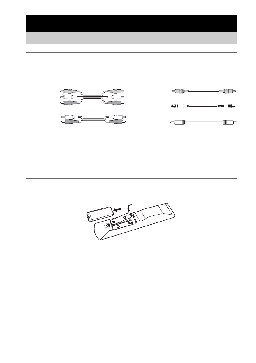
The hookup diagrams on the subsequent pages assume the use of the following optional connection
cords (A to E) (not supplied).
A Audio/video cord
Yellow (video)
White (L/audio)
Red (R/audio)
B Audio cord
White (L)
Red (R)
Notes
• Turn off the power to all components before making any connections.
• Be sure to make connections firmly to avoid hum and noise.
• When connecting an audio/video cord, be sure to match the color-coded pins to the appropriate jacks on the
components: yellow (video) to yellow; white (left, audio) to white; and red (right, audio) to red.
• When connecting optical digital cords, insert the cord plu gs straight in until they click into place.
• Do not bend or tie optical digital cords.
Inserting batteries into the remote
Insert two R6 (size AA) batteries with the + and – properly oriented in the battery compartment.
C Video cord
Yellow
D Optical digital cord
E Coaxial digital cord
Tip
Under normal conditions, the batteries should last for about 6 months. When the remote no longer operates the
control center, replace bot h batteries with new ones.
Notes
• Do not leave the remote in an extremely hot or humid place.
• Do not use a new battery with an old one.
• Do not expose the remote sensor of the control center to direct sunlight or lighting apparatuses. Doing so may cause
a malfunction.
• If you don’t use the remote for an extended period of time, remove the batteries to avoid possible damage from
battery leakage and corrosion.
• Turn off the power to all components before making any connections.
• Be sure to make connections firmly to avoid hum and noise.
GB
4
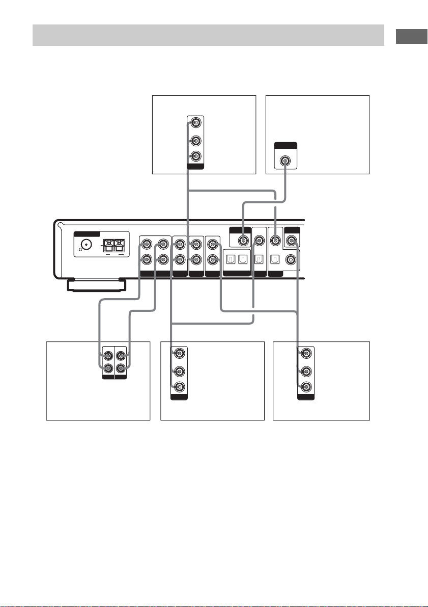
Connecting analog components
If you connect your TV to the MONITOR jack, you can watch the video from the selected input
(page 12).
For details on the required cords (A
–E), see page 4.
Hooking up the components
ANTENNA
U
75
FM
AM
l
B
LINE
LINE
INPUT OUTPUT
MD deck, Hard disc
L
R
L
R
l
INOUT
DVD player
VIDEO OUT
L
AUDIO OUT
R
OUTPUT
TV/SAT TV/SAT
HDD/MD
VIDEO OUT
L
AUDIO OUT
R
OUTPUT
VIDEODVD DVD
Satellite tuner
VIDEOINVIDEO
MONITOR
OUT
OPT OUT
OPT IN OPT IN OPT INININININOUT COAX IN
HDD/MD
INPUT
MONITOR IN
IN
TV monitor
CA
VIDEO
IN
AAB
VIDEO OUT
L
AUDIO OUT
R
OUTPUT
VCR
GB
5
.
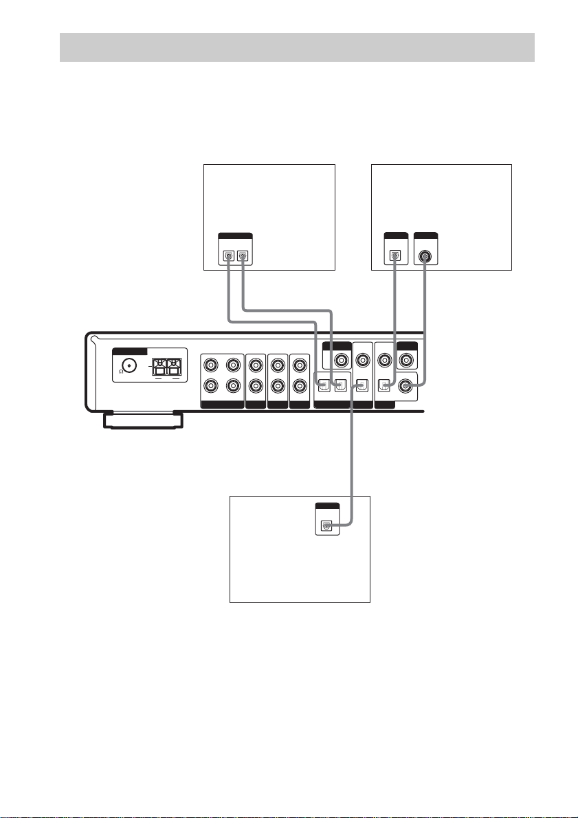
Connecting digital components
Connect the digital output jacks of your DVD player (etc.) to this system’s digital input jacks to bring
the multi channel surround sound of a movie theater into your home. To fully enjoy multi channel
surround sound, five speakers (two front speakers, two surround speakers, and a center speaker) and a
sub woofer are required.
For details on the required cords (A
–E), see page 4.
ANTENNA
75
FM
DIGITAL
IN
OPTICAL
OUT
D
VIDEO
DVD player
DIGITAL
COAXIAL
OUT
*
*
E
IN
MD deck, Hard disc
DIGITAL
OPTICAL
IN
OUT
DD
l
INOUT
l
VIDEOINVIDEO
MONITOR
U
L
AM
R
TV/SAT TV/SAT
HDD/MD
OUT
OPT OUT
OPT IN OPT IN OPT IN COAX IN
ININININOUT
VIDEODVD DVD
HDD/MD
D
DIGITAL
OPTICAL
OUT
Satellite tuner
* Connect to either the COAX IN or the OPT IN jack. We recommend making connections to the COAX IN jack.
Notes
• All the digital audio jacks are compatible with 32 kHz, 44.1 kHz, 48 kHz and 96 kHz sampling frequencies.
• To playback the multi channel surround sound through this receiver, you may have to change the digital output
setting on the connected component. For details, refer to the operating instructions supplied with the component.
GB
6
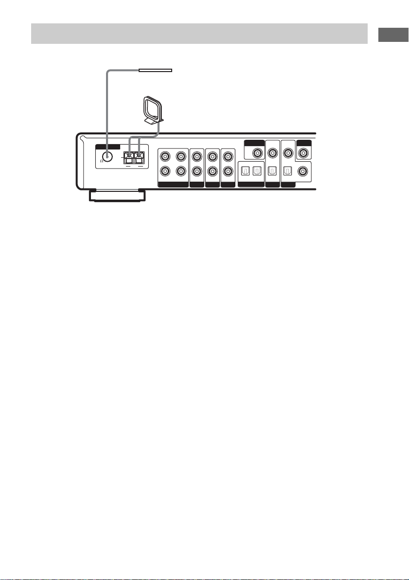
Connecting the antennas
Connect the supplied AM loop antenna and FM wire antenna.
FM wire antenna
(supplied)
AM loop antenna
(supplied)
VIDEOINVIDEO
ANTENNA
75
FM
U
L
AM
R
TV/SAT TV/SAT
HDD/MD
MONITOR
OUT
OPT OUT
OPT IN OPT IN OPT IN COAX IN
ININININOUT
VIDEODVD DVD
HDD/MD
Notes
• To prevent noise pickup, keep the AM loop antenna away from the receiver and other components.
• Be sure to fully extend the FM wire antenna.
• After connecting the FM wire antenna, keep it as horizontal as possible.
VIDEO
IN
IN
Hooking up the components
GB
7
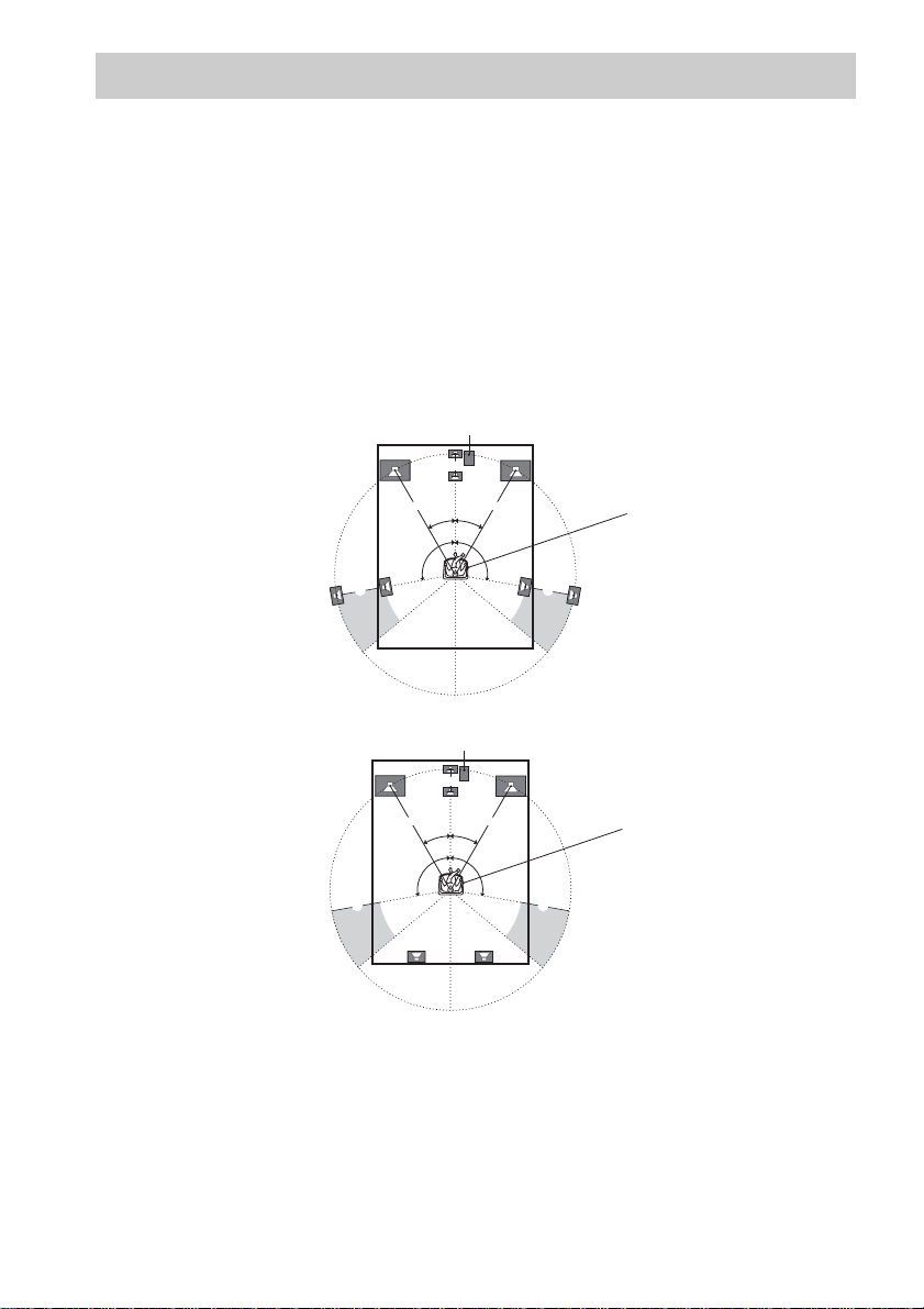
Placing speakers
To fully enjoy surround sound, configure your speakers as below.
• Place the front speaker in a location 1 to 7 meters from the listening position (A).
• You can enjoy a higher quality sound effect if you place the center speaker from a d istance equal to
the front speaker distance (A) to a distance 1.5 meters closer to your listening position (B).
• You can enjoy a higher quality sound effect if you place the surround speakers from a distance equ al
to the front speaker distance (A) to a distance 4.5 meters closer to your listening position (C).
• You can place the surround speakers either behind you or to the side, depending on the shape of your
room (etc.).
• Place the sub woofer at the same distance from the listening position as the front speaker (left or
right).
When placing surround speakers to your side
sub woofer
B
Note
A A
30˚30˚
100˚-120˚100˚-120˚
CC
When placing surround speakers behind you
sub woofer
B
A A
30˚30˚
100˚-120˚100˚-120˚
CC
Listening position
Listening position
Do not place the center speaker and surround speakers farther away from the listening position than the front
speakers.
GB
8
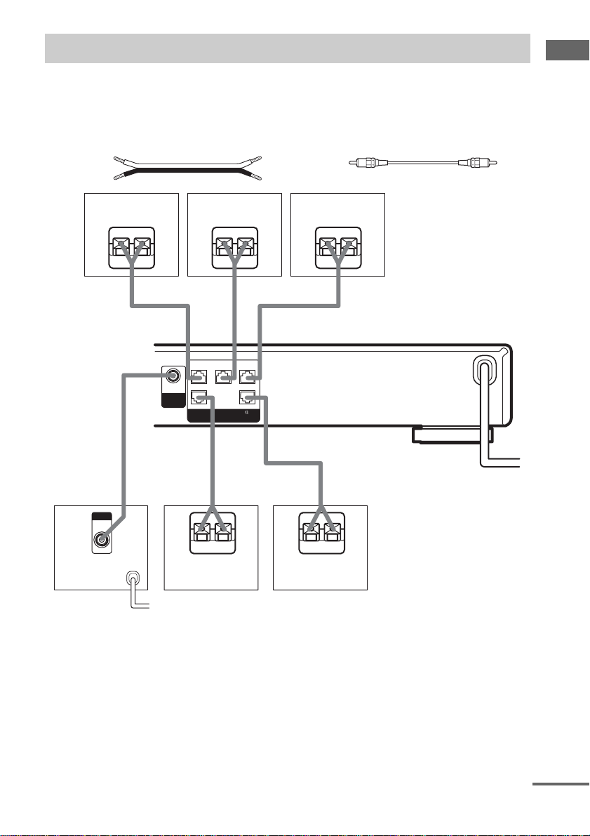
Connecting speakers
When connecting speaker cords, make sure to attach the supplied speaker plugs to the speaker cords.
For details on how to attach the speaker plugs, see the supplied flysheet.
Required cords
A Speaker cords (not supplied)
(+)
(–)
B Monaural audio cord (not supplied)
Black
Hooking up the components
Front speaker (R)
Center speaker
EeAEe
FRONT R
3#
AUDIO
#3
OUT
SUB
WOOFER
SURR R
(IMPEDANCE USE 4-16 )
B
INPUT
AUDIO
IN
Sub woofer
E
Surround speaker
(R)
b
To a wall outlet
(Switch the power
(POWER) to off bef ore
connecting the power
cord).
CENTER
3#
SPEAKERS
FRONT L
SURR L
3#
#3
eAE
Front speaker (L)
Ee
AA
A
Surround speaker
(L)
e
continued
GB
9
Note
If you use speakers with low maximum input rating,
adjust the volume carefully to avoid excessive output
on the speakers.
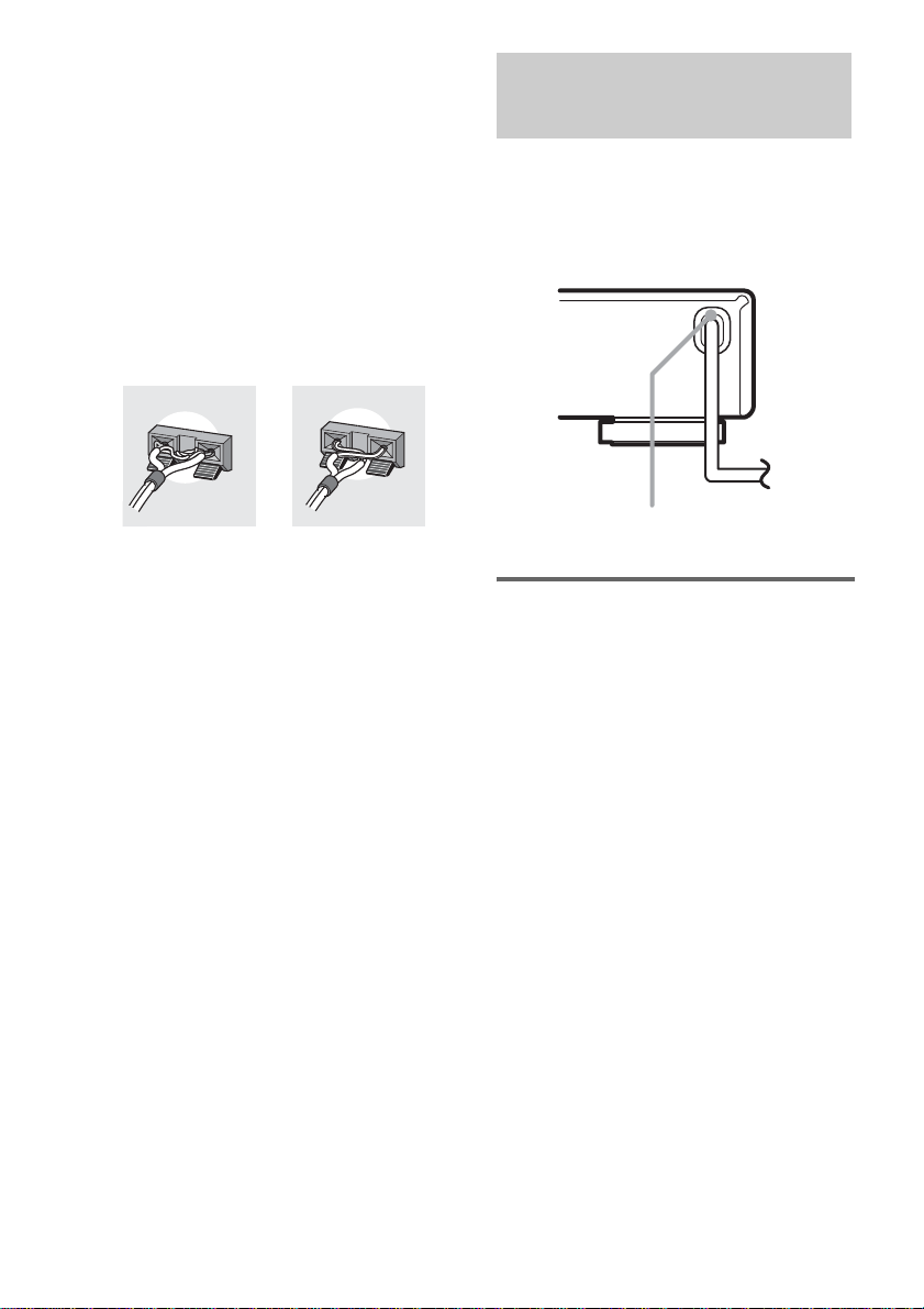
To avoid short-circuiting the
speakers
Short-circuiting may damage the speakers and
cause a malfunction.
Make sure the stripped ends of each
speaker cord does not touch the stripped
end of another speaker cord.
Examples of poor conditions of the speaker
cord
Connecting the AC power cord
Before connecting the AC power cord of this
receiver to a wall outlet, connect the speaker
system to the receiver.
Connect the AC power cord(s) of your audio/
video components to a wall outlet.
b
AC power
cord
Performing initial setup
operations
Before using the receiver for the first time,
initialize the receiver by performing the
following procedure.
This procedure can also be used to return
settings you have made to their factory defaults.
1 Press ?/1 to turn off the receiver.
2 Hold down ?/1 for 5 seconds.
All of the following items are reset or
cleared:
• All sound field parameters are reset to
their factory settings.
• All SET UP parameters are reset to th eir
factory settings.
• The sound fields memorized for each
program source and preset stations are
cleared.
• The master volume is set to “MIN”.
To a wall outlet
10
GB

Adjusting the speaker levels and balance
— TEST TONE
Use the remote while seated in your listening
position to adjust the level of each speaker.
1 Press ?/1 to turn on the receiver.
2 Rotate VOLUME on the receiver
clockwise.
3 Turn on the power of the sub woofer.
4 Press TEST TONE on the remote.
You will hear the test tone from each
speaker in sequence.
Front (left) t Center t Front (right) t
Surround (right) t Surround (left) t Sub
woofer
5 Adjust the LEVEL parameters so that
the level of the test tone from each
speaker sounds the same when you
are in your main listening position.
To adjust the balance and level of speakers,
press MAIN MENU repeatedly to select
LEVEL menu, press V/v to select the
parameter you want to adjust (page 26).
Then press B/b to select the setting.
6 Press TEST TONE on the remote again
to turn off the test tone.
Tip
You can adjust the level of all speakers at the same
time. Rotate VOLUME on the system or press
VOLUME +/– on the remote.
Notes
• The front balance, center level, surround level, and
sub woofer level are shown in the display during
adjustment.
• To enjoy the better sound quality, do not turn the
volume of the sub woofer too high.
Checking the connections
Hooking up the components
After connecting all of your components to the
receiver, do the following to verify that the
connections were made correctly.
1 Press ?/1 to turn on the receiver.
2 Press INPUT SELECTOR to select a
component (program source) that you
connected (e.g., DVD player).
3 Turn on the component and start
playing it.
4 Rotate VOLUME to turn up the volume.
If you do not obtain normal sound output after
performing this procedure, see
“Troubleshooting” on page 29 and take the
appropriate measures to correct the problem.
11
GB
 Loading...