

Page 1
Page 2

Getting Started
WARNING
To prevent fire or shock
hazard, do not expose
the unit to rain or
moisture.
To avoid electrical shock, do not open
the cabinet. Refer servicing to qualified
personnel only.
Do not install the appliance in a
confined space, such as a bookcase or
built-in cabinet.
For the customers in Canada
CAUTION
TO PREVENT ELECTRIC SHOCK, DO
NOT USE THIS POLARIZED AC PLUG
WITH AN EXTENSION CORD,
RECEPTACLE OR OTHER OUTLET
UNLESS THE BLADES CAN BE FULLY
INSERTED TO PREVENT BLADE
EXPOSURE.
Precautions
On safety
• Should any solid object or liquid fall
into the cabinet, unplug the receiver
and have it checked by qualified
personnel before operating it any
further.
On power sources
• Before operating the receiver, check
that the operating voltage is identical
with your local power supply. The
operating voltage is indicated on the
nameplate at the rear of the receiver.
• The receiver is not disconnected from
the AC power source (MAINS) as
long as it is connected to the wall
outlet, even if the receiver itself has
been turned off.
• If you are not going to use the
receiver for a long time, be sure to
disconnect the receiver from the wall
outlet. To disconnect the AC power
cord, grasp the plug itself; never pull
the cord.
• Should the AC power cord need to be
changed, have it done at a qualified
service shop only.
On placement
• Place the receiver in a location with
adequate ventilation to prevent heat
build-up and prolong the life of the
receiver.
• Do not place the receiver near heat
sources, or in a place subject to direct
sunlight, excessive dust or
mechanical shock.
• Do not place anything on top of the
cabinet that might block the
ventilation holes and cause
malfunctions.
On operation
• Before connecting other components,
be sure to turn off and unplug the
receiver.
On cleaning
• Clean the cabinet, panel and controls
with a soft cloth slightly moistened
with a mild detergent solution. Do
not use any type of abrasive pad,
scouring powder or solvent such as
alcohol or benzine.
If you have any question or problem
concerning your receiver, please
consult your nearest Sony dealer.
US
2
Page 3

Getting Started
About This Manual
The instructions in this manual are for
models STR-DE535 and STR-DE435.
Check your model number by looking
at the upper right corner of the front
panel or lower right corner of the
remote. In this manual, the STR-DE535
is the model used for illustration
purposes, any difference in operation is
clearly indicated in the text, for
example, “STR-DE535 only”.
Type of differences
Model
Feature
PHONO
CONTROL A1 II
Conventions
The instructions in this manual describe
the controls on the receiver. You can
also use the controls on the remote if
they have the same or similar names as
those on the receiver. For details on the
use of your remote, refer to the separate
operating instructions supplied with the
remote.
• A “Quick Reference Guide” is
supplied on page 29.
• The following icons are used in this
manual:
Indicates that you can use only
the remote to do the task.
Indicates hints and tips for
making the task easier.
This receiver contains a Dolby Pro Logic
Surround decoder.
Manufactured under license from Dolby
Laboratories Licensing Corporation.
“Dolby , “Pro Logic” and the double-D
a symbol are trademarks of Dolby
Laboratories Licensing Corporation.
•
•
DE435DE535
TABLE OF CONTENTS
Getting Started
Unpacking 4
Hookup Overview 4
Antenna Hookups 5
Audio Component Hookups 5
Video Component Hookups 6
Speaker System Hookups 7
AC Hookups 9
Before You Use Your Receiver 9
Dolby Surround Setup 10
Location of Parts and Basic Amplifier Operations
Front Panel Parts Description 12
Receiver Operations
Receiving Broadcasts 15
Presetting Radio Stations 16
Using Surround Sound
Enjoying Surround Sound 17
Selecting a Sound Field 18
Customizing Sound Fields 19
Other Operations
Indexing Preset Stations and Program Sources 21
Recording 21
Using the Sleep Timer 22
Adjustments Using the SET UP Button 23
Additional Information
Troubleshooting 24
Specifications 25
Glossary 26
Index 27
US
Rear Panel Descriptions 28
Quick Reference Guide 29
US
3
Page 4
Getting Started
Unpacking
Check that you received the following items with the
receiver:
• FM wire antenna (1)
• AM loop antenna (1)
• Remote commander (remote) (1)
Model Remote
STR-DE535 RM-LJ302
STR-DE435 RM-PP402
• LR6 (size-AA) batteries (3) (STR-DE535 only)
• R6 (size-AA) batteries (2) (STR-DE435 only)
• Operating Instructions of the remote (1)
• Operating Instructions of CONTROL A1 II (1)
(STR-DE535 only)
Inserting batteries into the remote
Insert the LR6 (STR-DE535) or R6 (STR-DE435) (Size
AA) batteries with the + and – properly oriented in the
battery compartment. When using the remote, point it
at the remote sensor
DE435) on the receiver.
For details, refer to the operating instructions supplied
with your remote.
You cannot operate the following buttons on the
RM-PP402 remote (STR-DE435 only)
• VIDEO2
• VIDEO3
• DVD
• PHONO
• SOUND FIELD A. F. D.
(STR-DE535) or g (STR-
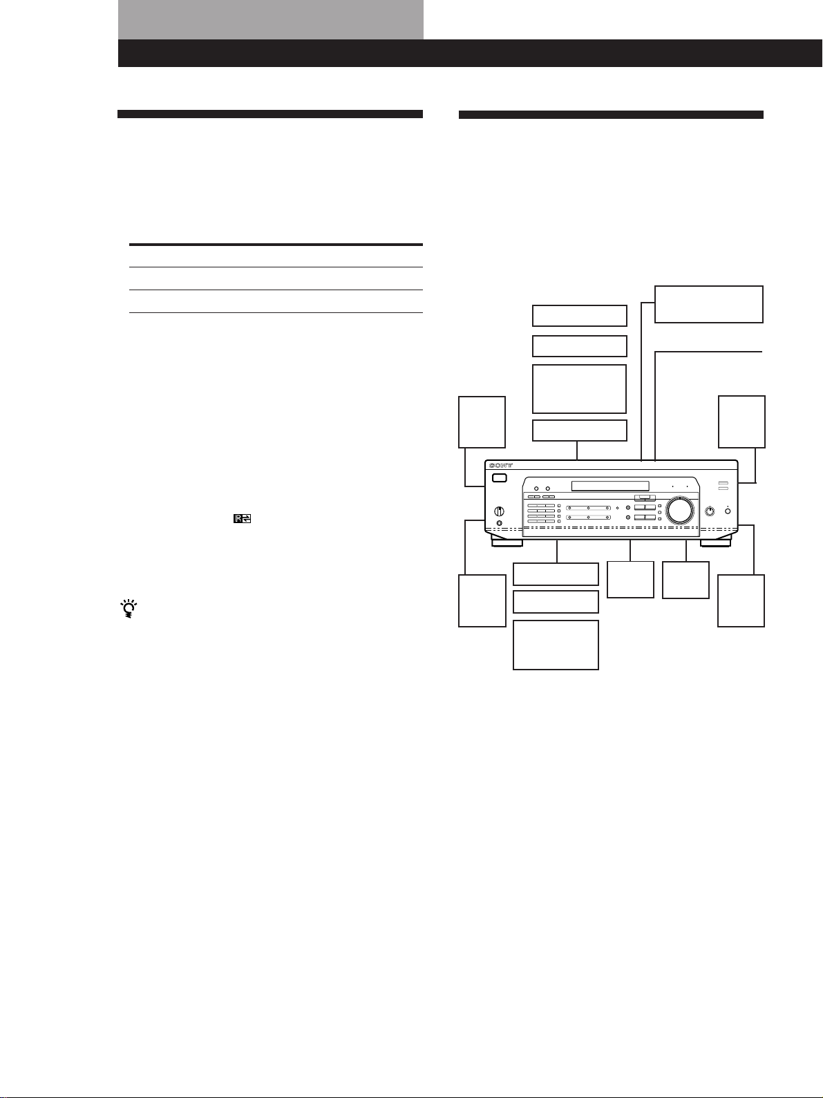
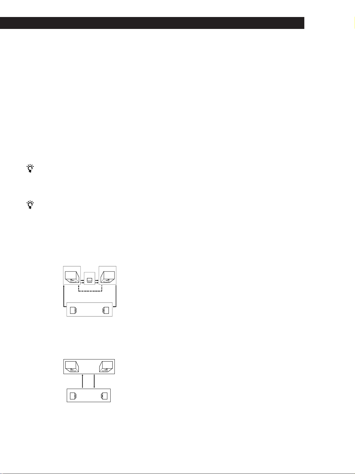
Hookup Overview
The receiver allows you to connect and control the
following audio/video components. Follow the
hookup procedures for the components that you want
to connect to the receiver on the pages specified. To
learn the locations and names of each jack, see “Rear
Panel Descriptions” on page 28.
Video Component
Speaker
System
Hookups (7)
Front
speaker
(L)
Rear
speaker
(L)
Hookups (6)
TV monitor
TV tuner
SAT (Satellite
receiver)/LD
player
VCR
CD player
MD/Tape deck
Turntable
(STR-DE535
only)
Audio Component
Hookups (5)
Center
speaker
DVD player/AC-3
decoder
Antenna Hookups (5)
AM/FM antenna
Front
speaker
(R)
Active
woofer
Rear
speaker
(R)
Before you get started
Notes
• Do not leave the remote in an extremely hot or humid
place.
• Do not use a new battery with an old one.
• Do not expose the remote sensor to direct sunlight or
lighting apparatuses. Doing so may cause a malfunction.
• If you don’t use the remote for an extended period of time,
remove the batteries to avoid possible damage from
battery leakage and corrosion.
US
4
• Turn off the power to all components before making
any connections.
• Do not connect the AC power cords until all of the
connections are completed.
• Be sure to make connections firmly to avoid hum
and noise.
• When connecting an audio/video cable, be sure to
match the color-coded pins to the appropriate jacks
on the components: Yellow (video) to Yellow; White
(left, audio) to White; and Red (right, audio) to Red.
Page 5
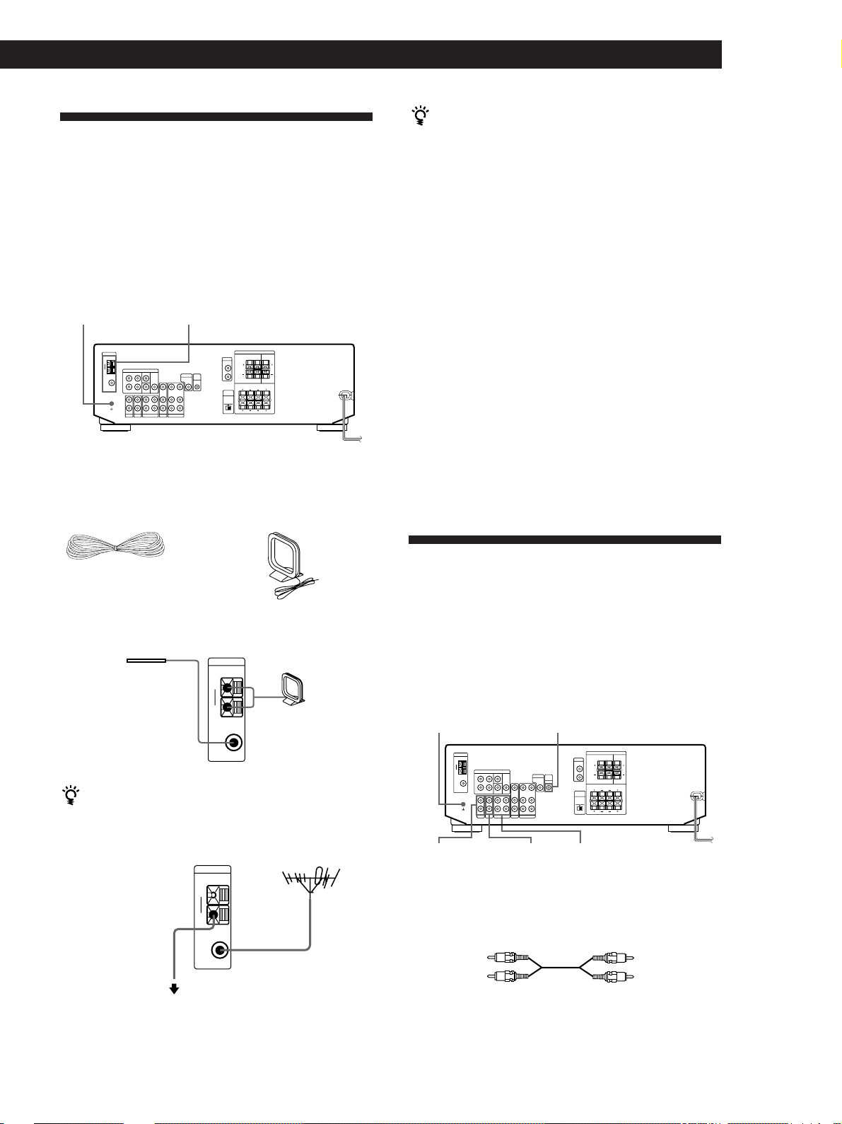
Antenna Hookups
Overview
Getting Started
If you have poor AM reception
Connect a 20 to 50 ft. (6 to 15-meter) insulated wire (not
supplied) to the AM antenna terminal in addition to the
AM loop antenna. Try to extend the wire outdoors and
keep it horizontal.
This section describes how to connect AM and FM
antennas to the receiver. If you want to receive radio
broadcasts with the receiver, complete these
connections first, then go to the following pages.
For specific locations of the terminals, see the
illustration below.
y (STR-DE535 only)
ANTENNA
What antennas will I need?
• FM wire antenna
(supplied) (1)
• AM loop antenna
(supplied) (1)
Connecting a ground wire
If you connect the receiver to an outdoor antenna,
ground it against lightning as shown in the illustration
in the left column. To prevent a gas explosion, do not
connect the ground wire to a gas pipe.
Note (except STR-DE435)
Do not use the SIGNAL GND y terminal for grounding the
receiver.
Where do I go next?
If you want to connect other components, go on to the next
section. If you’re only planning to use the receiver to listen
to the radio, go to “Speaker System Hookups” on pages 7
and 8.
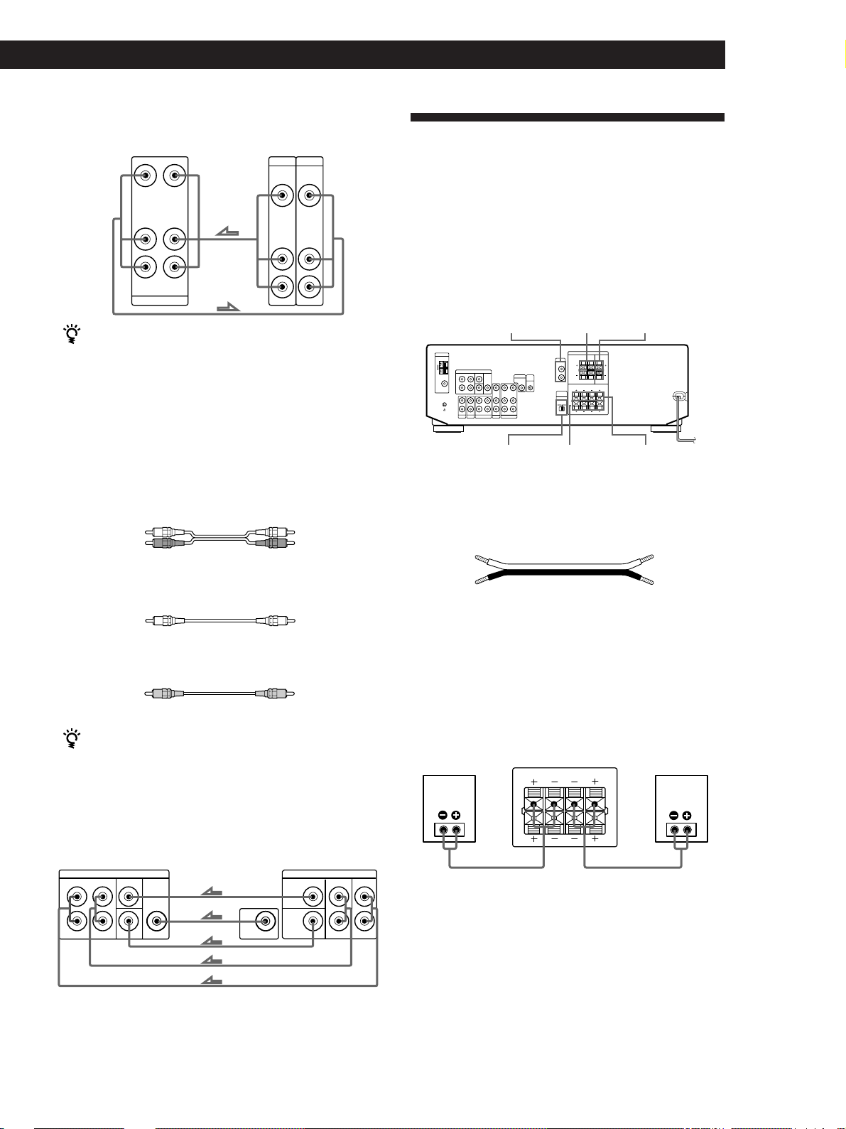
Audio Component Hookups
Overview
Hookups
FM wire antenna
After connecting
the wire antenna,
keep it as
horizontal as
possible.
If you have poor FM reception
Use a 75-ohm coaxial cable (not supplied) to connect the
receiver to an outdoor FM antenna as shown below.
Ground wire
(not supplied)
To ground
Receiver
ANTENNA
AM
y
COAXIAL
FM
75Ω
Receiver
ANTENNA
AM
y
COAXIAL
FM
75Ω
AM loop antenna
FM outdoor antenna
This section describes how to connect your audio
components to the receiver. If you want to use the
receiver as an amplifier, complete these connections.
For specific locations of the jacks, see the illustration
below.
y (STR-DE535 only)
PHONO
(STR-DE535 only)
CTRL A1 II (STR-DE535 only)
CD MD/TAPE
What cables will I need?
Audio cords (not supplied) (1 for each CD player or
turntable; 2 for each MD recorder or tape deck)
White (L)White (L)
Red (R)Red (R)
(continued)
US
5
Page 6
Getting Started
AUDIO IN
L
R
TV/LD
VIDEO IN
AUDIO
OUTPUT
VIDEO
L
R
Hookups
The arrow ç indicates signal flow.
CD player
Receiver
L
R
AUDIO IN
CD
Turntable (STR-DE535 only)
CD player
OUTPUT
LINE
Video Component Hookups
Overview
This section describes how to connect video
components to the receiver. For specific locations of the
L
R
jacks, see the illustration below.
5.1 CH/DVD
MONITOR
Receiver
L
R
AUDIO IN
PHONO
Turntable
OUTPUT
LINE
L
R
• If your turntable has an earth lead
To prevent hum, connect the earth lead to the y ground
terminal on the receiver.
MD recorder or Tape deck
Receiver
REC OUT
MD/TAPE
IN
MD recorder or Tape deck
OUTPUT
L
R
LINE
INPUT
LINE
L
R
CONTROL A1 II (STR-DE535 only)
Receiver
CTRL
A1 II
CD player, MD recorder
or Tape deck
CTRL
A1 II
VIDEOTV/SAT
(TV/LD)
What cables will I need?
• Audio/video cable (not supplied) (1 for each TV tuner,
Satelllite receiver or LD player; 2 for the VCR)
Yellow
White (L)
Red (R)
Yellow
White (L)
Red (R)
• Video cable (not supplied) (1 for a TV monitor)
Yellow
Yellow
Hookups
The arrow ç indicates signal flow.
TV/SAT (TV/LD)
Receiver
TV tuner or Satellite
receiver or LD player
If you have a CONTROL A1 II-compatible Sony CD player,
MD recorder or tape deck
Use a CONTROL A1 II cord (not supplied) to connect the
CTRL A1 II jack on the CD player, MD recorder or tape deck
to the CTRL A1 II jack on the receiver. Refer to the separate
manual “CONTROL-A1 II Control System” and the
operating instructions supplied with your CD player, MD
recorder or tape deck for details.
MONITOR
MONITOR
VIDEO
OUT
TV monitorReceiver
INPUT
VIDEO
Where do I go next?
Go on to the next section to connect video components to
US
6
enjoy surround sound when watching/listening to TV
programs or video tapes.
Page 7
VCR
Receiver VCR
VIDEO IN
VIDEO OUT
L
R
AUDIO IN
AUDIO OUT
VIDEO
Use the function buttons (TV/SAT (TV/LD), CD, MD/
TAPE etc.) to select the VIDEO AUDIO OUT signal.
You can record this audio signal by connecting a
recording component such as a cassette deck (to the
VIDEO AUDIO OUT jack).
OUTPUT
VIDEO
AUDIO
INPUT
VIDEO
AUDIO
L
R
DVD player/AC-3 decoder
What cables will I need?
• Audio cable (not supplied) (1 for each 5.1 CH/DVD
FRONT and REAR jacks)
White (L)
Red (R)
• Monaural audio cable (not supplied) (1 for each 5.1 CH/
DVD CENTER and WOOFER jacks)
Black
• Video cable (not supplied) (1 for the 5.1 CH/DVD VIDEO
IN jack)
White (L)
Red (R)
Black
Getting Started
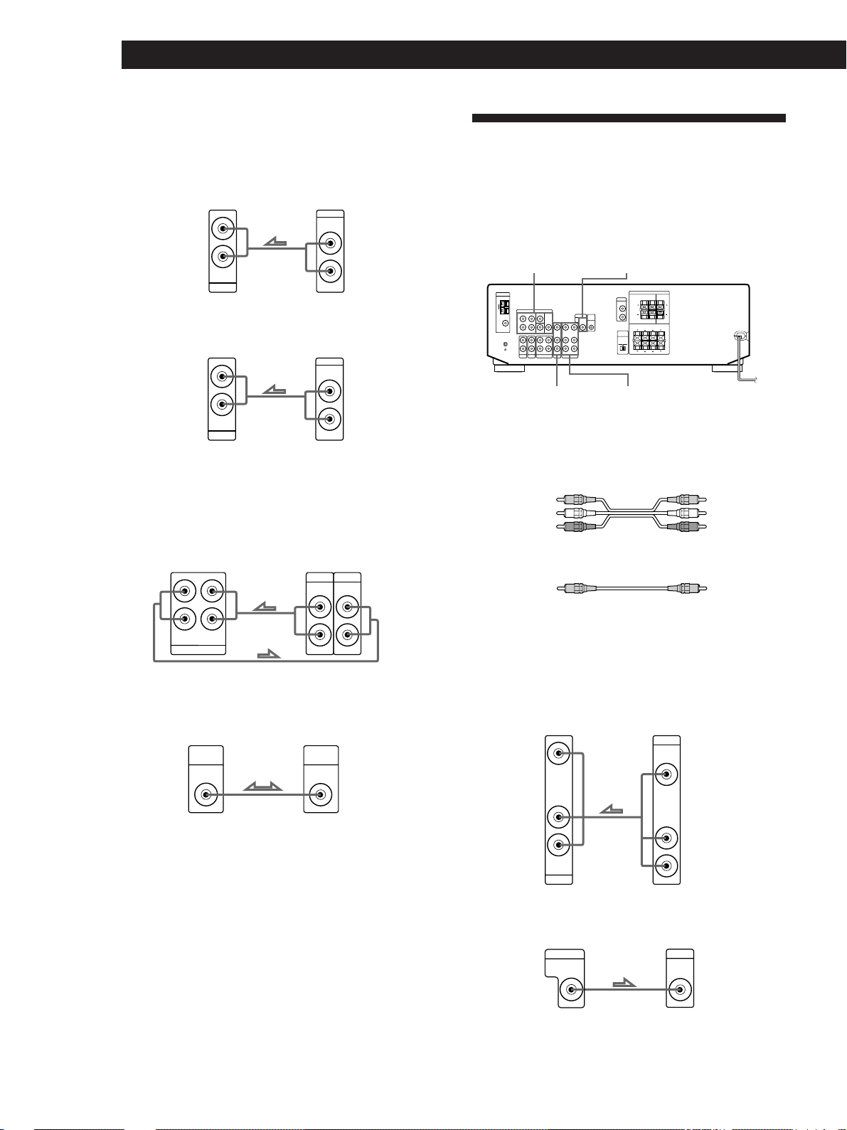
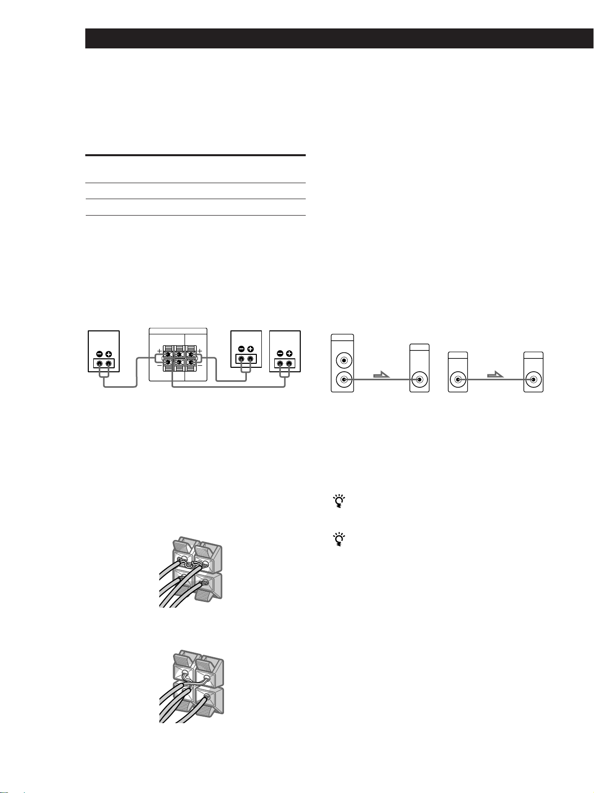
Speaker System Hookups
Overview
This section describes how to connect your speakers to
the receiver. To enjoy surround effects, center and rear
speakers and an active woofer are required. For
specific locations of the terminals, see the illustration
below:
SPEAKERS
WOOFER
IMPEDANCE
SELECTOR
What cords will I need?
Speaker cord (not supplied) (1 for each speaker)
(–)
Twist the stripped ends of the cord about 2/3 inch (15 mm).
Be sure to match the speaker cord to the appropriate
terminal on the components: + to + and – to –. If the cords
are reversed, the sound will be distorted and will lack bass.
REAR
SPEAKERS
FRONT B
SPEAKERS CENTER
SPEAKERS
FRONT A
(+)(+)
(–)
Yellow
Yellow
You can play decoded Dolby Digital AC-3
soundtracks through the speakers connected to the
amplifier.
If you have a Dolby Digital AC-3 decoder you can
amplify a decoded Dolby Digital AC-3 soundtrack with
the following connections.
Dolby Digital AC-3
Receiver
5.1 CH / DVD
FRONT FRONTREAR REARCENTER
L
R
WOOFER
VIDEO
VIDEO IN
decoder, etc.
CENTER
WOOFER
Where do I go next?
Go on to the next section to connect the speakers.
PRE OUT
Hookups
Front speakers
Front speaker
(R)
Receiver
FRONT
R
R
Front speaker
(L)
L
AA
BB
L
(continued)
US
7
Page 8
Getting Started
REAR
+
–
R
R
L
–
WOOFER
AUDIO
OUT
INPUT
Selecting the impedance
Set the IMPEDANCE SELECTOR for the front speakers
as indicated in the table below. Check the instruction
manual of your speakers if you’re not sure of the
impedance. (This information is usually printed on a
label on the back of the speaker.)
If the nominal impedance of
your speaker is
Between 4 and 8 ohms
8 ohms or higher
Set IMPEDANCE SELECTOR
to
4Ω
8Ω
Note
Be sure to connect the front speakers with nominal
impedance of 8 ohms or higher if you want to select both
sets of front speakers (see page 12).
Rear and center speakers
Rear speaker
(R)
Receiver
SPEAKERS
REAR
LR
LR
Center speaker
CENTER
Rear speaker
(L)
After connecting all the components, speakers, and AC
power cord, output a test tone to check that all the
speakers are connected correctly. For details on
outputting a test tone, refer to “Adjusting the speaker
volume” on page 10.
If you have connected rear speakers, be sure to press
the 5.1 CH/DVD button and turn off sound field on
the receiver before outputting a test tone so that the
tone is output individually from the left and right rear
speakers.
If no sound is heard from a speaker while outputting a
test tone or a test tone is output from a speaker other
than the one whose name is currently displayed on the
receiver, the speakers may be short-circuited. If this
happens, check the speaker connection again.
Active woofer
* STR-DE535 only STR-DE435 only
Receiver
Active woofer
Receiver
WOOFER
AUDIO
OUT
Active woofer
INPUT
To avoid short-circuiting the speakers
Short-circuiting of the speakers may damage the
receiver. To prevent this, make sure to take the
following precautions when connecting the speakers.
Make sure the stripped ends of each speaker cord does
not touch another speaker terminal or the stripped end
of another speaker cord.
Examples of poor conditions of the speaker cord:
Stripped speaker cord is touching another speaker
terminal
+
REAR
R
R
L
* You can connect the active woofer to either of the two
jacks. The remaining jack can be used to connect a second
active woofer.
Note
Do not connect any other component.
If you have an additional front speaker system
Connect them to the SPEAKERS FRONT B terminals.
If your TV monitor uses separate speakers
You can connect one of them to the SPEAKERS
CENTER terminals for use with Dolby Pro Logic
Surround sound (see page 10).
Where do I go next?
To complete your system, go to “AC Hookups” on page 9.
Stripped cords are touching each other due to excessive
US
8
removal of insulation.
Page 9
Getting Started
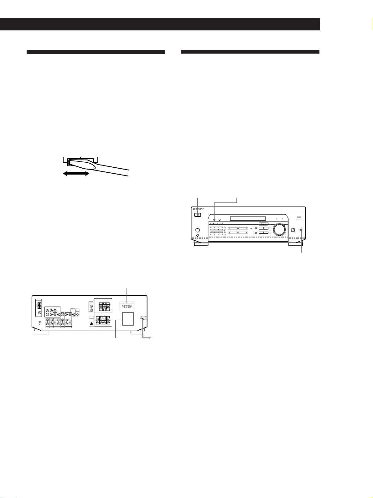
AC Hookups
Setting the voltage selector (except for
Canada, Australia, Singapore and Malaysia
models)
Check that the voltage selector on the rear panel of the
player is set to the local power line voltage. If not, set
the selector to the correct position using a screwdriver
before connecting the AC power cord to a wall outlet.
120 V 240 V 220 V
Connecting the AC power cord
Connect the AC power cord from this receiver and
from your audio/video components to a wall outlet.
If you connect other audio components to the
SWITCHED AC OUTLET on the receiver, the receiver
can supply power to the connected components so you
can turn on/off the whole system when you turn on/
off the receiver.
Before You Use Your Receiver
Before turning on the receiver
Make sure that you have:
• Turned MASTER VOLUME to the leftmost
position (0).
• Selected the appropriate front speakers (see “Front
Panel Parts Description” on page 12).
• Set BALANCE to the centre position.
Clearing the receiver's memory
Before you use your receiver for the first time or when
you want to clear the receiver's memory, do the
procedure below:
1/u (power)
DIMMER
MUTING
VOLTAGE SELECTOR
(except Canada, Australia,
Singapore and Malaysia
models) (STR-DE535 only)
/
SWITCHED AC OUTLET
Caution
Make sure that the power consumption of the component
connected to the receiver’s AC outlet does not exceed 100
watts. Do not connect high-wattage electrical home
appliances such as electric irons, fans, or TVs to this outlet.
to a wall outlet
Where do I go next?
Before you use the receiver, go to the next section to make
sure that all the controls are set to the appropriate positions.
1 Turn off the receiver.
2 Press 1/u (power) for more than 4 seconds.
“ALL CLEAR” appears in the display and the
items including the following are reset or cleared:
• All preset stations are reset to their factory
settings.
• All sound field parameters are reset to their
factory settings.
• All index names (of preset stations and program
sources) are cleared.
• All adjustments made with the SET UP button
are reset to their factory settings.
• The sound field memorized for each program
source and preset station is cleared.
After turning on the receiver
Check the following indicator:
• Press MUTING or MUTING on the remote if the
MUTING indicator turns on.
• Press DIMMER to set the display at any of four levels
of brightness.
US
9
Page 10
Getting Started
Dolby Surround Setup
3 Use + or – to select the center mode you want.
A description of each center mode is as follows:
Dolby Pro Logic Surround is a system for decoding
Dolby Surround sound that is standardized for TV
programs and movies. By selecting the proper centre
mode and adjusting the speaker volume, you can
reproduce highly precise localization and dynamic
panning of sounds of Dolby Surround encoded
software.
To obtain the best possible surround effect, you will
require at least one additional pair of speakers and/or
a centre speaker.
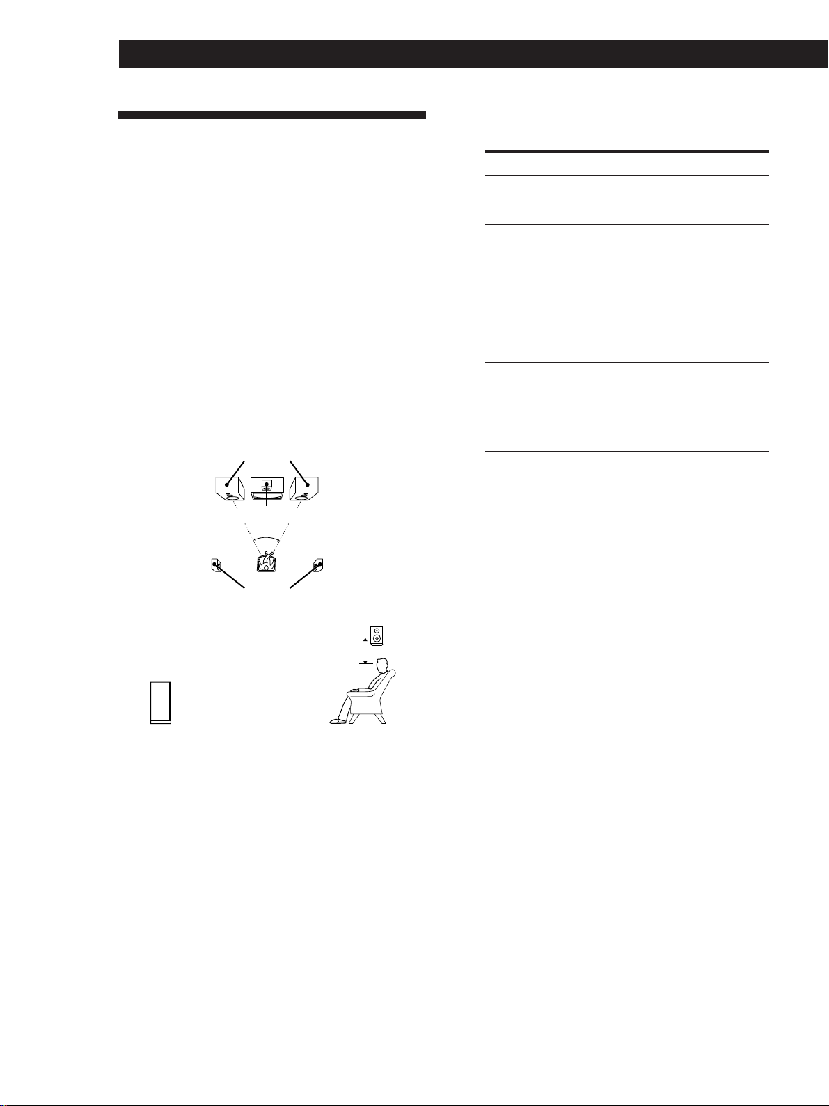
Locating the speakers
For optimum Dolby Pro Logic Surround sound, locate
your speakers as shown below.
Front speakers
Center speaker
45°
Rear speakers
Rear speaker
2 to 3 ft.
(60 - 90 cm)
Front speaker
If you have
Front and rear
speakers, but no
center speaker
Front and center
speakers, but no
rear speaker
Front and rear
speakers, and a
small center
speaker
Front and rear
speakers, and a
center speaker
that is equivalent
to your front
speakers
Select
PHANTOM
3 STEREO
(3-CH LOGIC)
NORMAL
WIDE
So that
The sound of the center
channel is output from
the front speakers
The sound of the rear
channel is output from
the front speakers
The bass sound of the
center channel is
output from the front
speakers (because a
small speaker cannot
produce enough bass)
The center channel
fully reproduces the
entire audio spectrum
Adjusting the speaker volume
The test tone feature lets you set the volume of your
rear speakers and/or center speaker to the same level
as that of the front speakers to maximize the Dolby Pro
Logic Surround effect. (If all of your speakers are equal
in performance, you don't have to adjust the speaker
volume.)
Using the controls on the remote, you can adjust the
volume level from wherever you're listening.
1 Make sure that the centre mode is correctly set
(see the table on this page).
10
US
Selecting the center mode
The receiver offers you four center modes:
PHANTOM, 3 STEREO, NORMAL, and WIDE. Each
mode is designed for a different speaker configuration.
Select the mode that best suits the speakers you use.
1 Press SET UP.
2 Press MENU < or > repeatedly until “CTR
MODE” (center mode) appears in the display.
2 Press SOUND FIELD ON/OFF to turn on the
sound field.
3 Press SOUND FIELD MODE +/– repeatedly to
select “PRO LOGIC.”
4 Press TEST TONE on the supplied remote.
You will hear a test tone (see next page) from each
speaker sequentially.
Page 11
Getting Started
5 Adjust the volume level so that the volume of the
test tone from each speaker sounds the same from
where you are listening.
• To adjust the balance of the front right and front
left speakers, use the BALANCE control on the
front of the main unit.
• To adjust the volume level of the center speaker,
press the LEVEL CENTER +/– buttons on the
remote.
• To adjust the volume level of the rear speakers,
press the LEVEL REAR +/– buttons on the
remote.
6 Press TEST TONE on the remote again to turn off
the test tone.
You can adjust the volume level of all speakers at
the same time
Rotate MASTER VOLUME on the main unit or press
MASTER VOL(UME) +/– on the remote.
What is a test tone?
A test tone is a signal that is produced by the receiver
and used to adjust speaker volume. The test tone is
output from speakers in the following two ways:
• When NORMAL, WIDE, or 3 STEREO mode is selected
The test tone is output from the front L (left), center,
front R (right), and rear speakers (except for 3
STEREO mode) in succession.
Increasing the output level of the rear
speaker by 5dB
The adjustment range of the rear speakers is preset
from –15 to + 10, but you can shift the range up 5 levels
(– 10 to + 15).
1 Press SET UP.
2 Press MENU < or > repeatedly until “REAR
GAIN” appears in the display.
3 Press + or – to select “GAIN UP”.
Note
The value for the rear level remain fixed at –15 to +10 in the
display, but you will be able to hear the difference in the
actual output.
To restore the normal output level
Repeat the procedure above, selecting “GAIN NORM”
in step 2.
Front (L) Front (R)
Center
3 STEREO
Rear (L, R)
NORMAL/WIDE
• When PHANTOM mode is selected
The test tone is output from the front and the rear
speakers alternately.
Front (L, R)
Test tone
Rear (L, R)
PHANTOM
See the table on page 20 for information on the output of
the test tone for sound fields other than PRO LOGIC.
Test tone
11
US
Page 12
Location of Parts and Basic Amplifier Operations
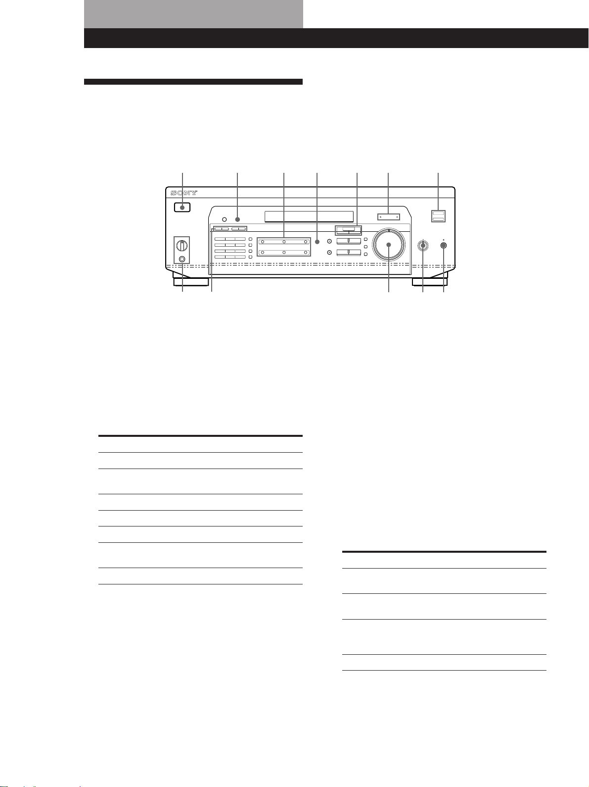
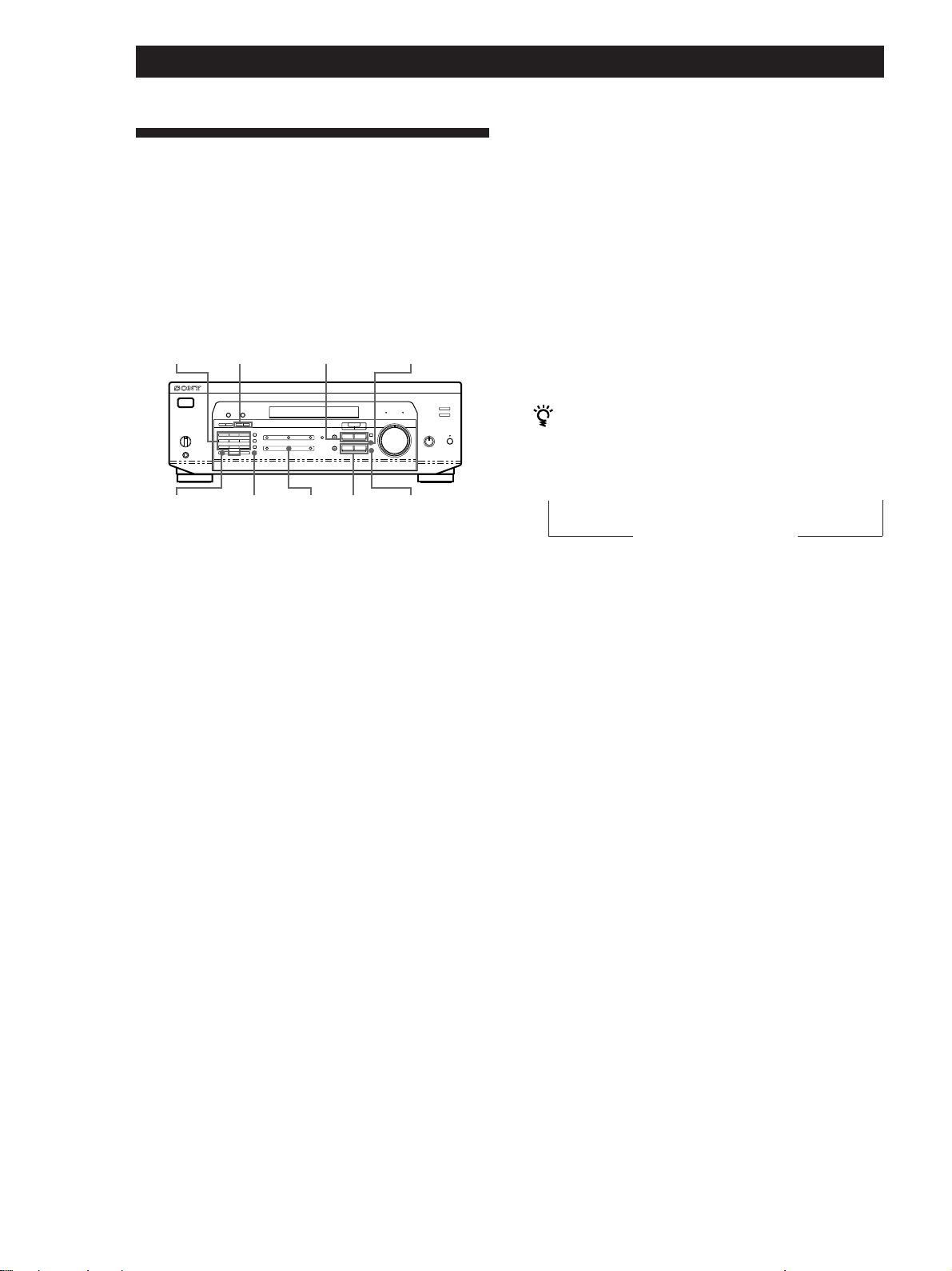
Front Panel Parts Description
This chapter gives you the information on the location
and function of the buttons and controls on the front
panel and explains basic amplifier operations.
1
823 !º
9
!¡
7!™
1 1/u switch
Press to turn the receiver on and off.
Note
Before you turn on the receiver, make sure that you have
turned the MASTER VOLUME control to the leftmost
position to avoid damaging your speakers.
2 Function buttons
Press to select the component you want to use.
To listen to or watch
Video tapes
TV programs, Satellite receiver
or Laser disc
MiniDiscs or audio tapes
Compact discs (CD)
Radio programs
Records
DVD player/AC-3 decoder
Press
VIDEO
TV/SAT (TV/LD)
MD/TAPE
CD
TUNER
PHONO
(except STR-DE435)
5.1 CH/DVD
After selecting the component, turn on the
component you selected and play the program
source.
4
56
3 5.1 CH/DVD button
Press to select the component connected to the 5.1
CH/DVD jacks. The 5.1 CH/DVD indicator lights
up when the component is selected.
4 MASTER VOLUME control
After turning on the component you selected, rotate
to adjust the volume.
5 MUTING button
Press to mute the sound. The MUTING indicator
lights up when the sound is muted.
6 BALANCE control
Rotate to adjust the balance of the front speakers.
7 SPEAKERS selector
Set according to the front speakers you want to
drive.
To select
Speakers connected to the SPEAKERS
FRONT A terminals
Speakers connected to the SPEAKERS
FRONT B terminals
Speakers connected to both the SPEAKERS
FRONT A and B terminals (parallel
connection)
No front speaker output
Set to
A + B*
A
B
OFF
12
US
Do not set to A+B when a sound field is turned on.
*
Be sure to connect the front speakers with nominal
impedance of 8 ohms or higher if you want to select both
sets of front speakers.
Page 13

Location of Parts and Basic Amplifier Operations
PHONES jack
Connects headphones.
Note
To use the headphones, set the SPEAKERS selector to OFF
to output sound to the headphones.
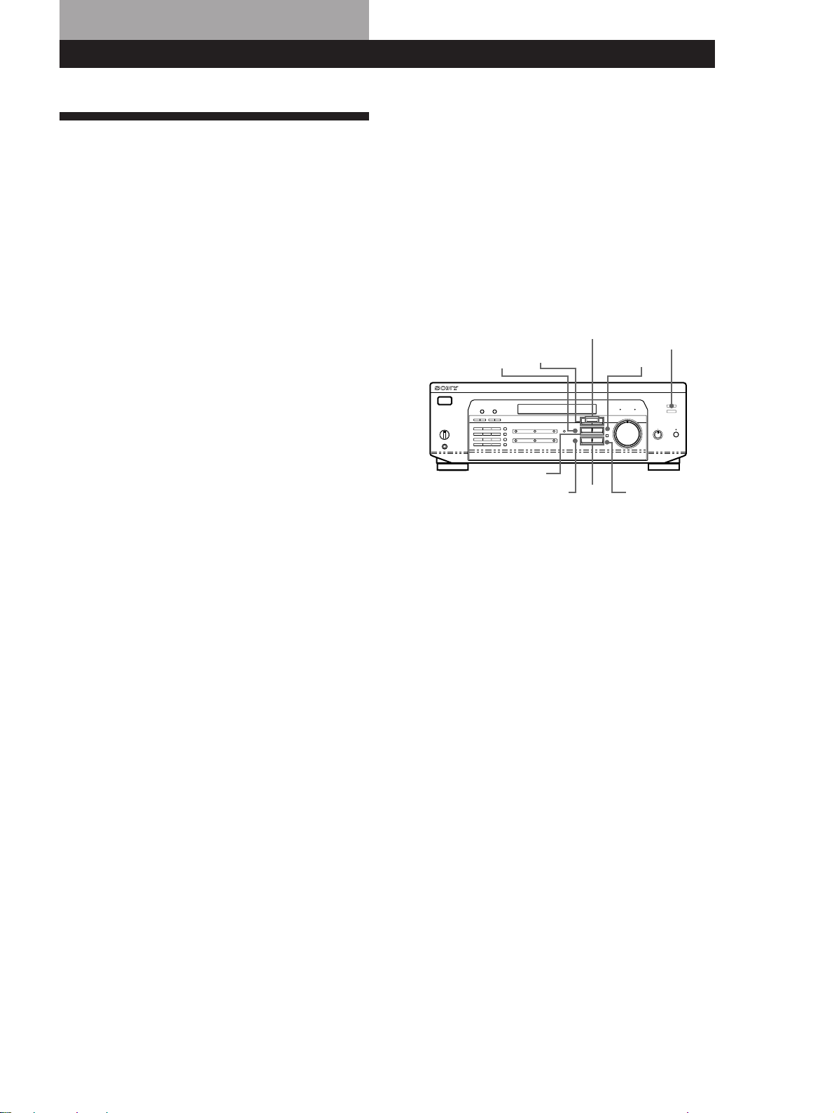
8 DISPLAY button
Press repeatedly to change the information on the
display window as follows:
v
Index name of the component or the preset station*
v
FUNCTION button indication or
frequency**
v
Sound field applied to the program source
Index name appears only when you have assigned one to the
*
component or the preset station (see page 21).
Frequency appears only when the tuner is selected.
**
9 Use the following buttons to enjoy surround sound.
For details, see “Enjoying Surround Sound”
starting from page 17.
SOUND FIELD ON/OFF button
Press to turn the sound field on or off.
SOUND FIELD MODE +/– button
Press to select a sound field from the group you
selected.
0 TONE button
Press to turn the tone effect on or off. The TONE
indicator lights up while the tone effect is turned
on.
Note that if you have adjusted the tone using the
MENU </> and +/– buttons, the adjusted tone will
be produced whenever you turn on the tone effect.
BASS BOOST button
Press to increase the bass of the front speakers. The
BASS BOOST indicator lights up when the function
is turned on.
!¡ TONE indicator
Lights up while the tone effect is turned on.
BASS BOOST indicator
Lights up while the bass boost is turned on.
When you want to enjoy high quality sound
Do the procedure below to bypass the sound control
circuits.
1 Set SOUND FIELD ON/OFF to off.
2 Set TONE to off.
3 Set BASS BOOST to off.
The result will be a two-channel stereo sound output
from the front speakers that is highly faithful to the
program source.
!™ The following buttons operate the built-in tuner.
For details, see “Receiving Broadcasts” starting
from page 15. Note that these buttons are operable
only when the tuner is selected.
PRESET TUNING +/– buttons
Press to scan all preset stations.
TUNING +/– buttons
Press to scan all the available radio stations.
(continued)
13
US
Page 14
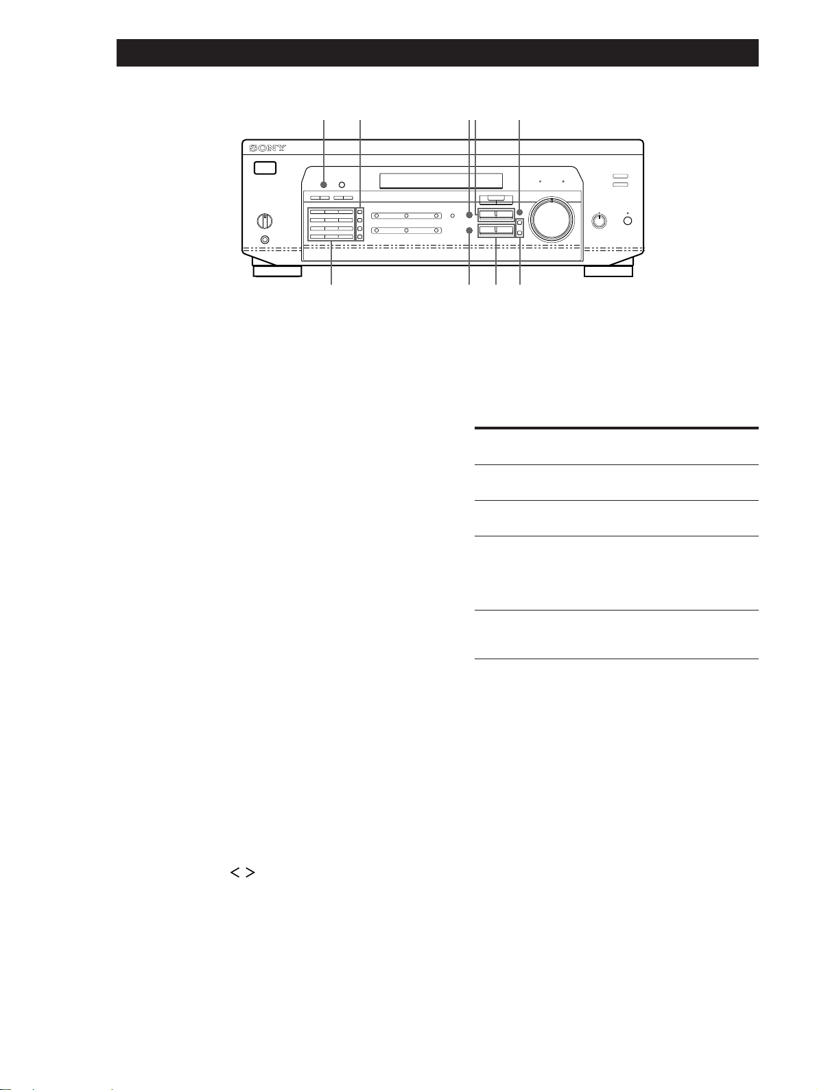
Location of Parts and Basic Amplifier Operations
@
¡
!£ !ª!∞ !¶
!¢ @º !§ !•
!£ The following buttons operate the built-in tuner.
For details, see “Receiving Broadcasts” starting
from page 15.
AM button
Selects the AM band.
FM button
Selects the FM band.
FM MODE button
If “STEREO” flashes in the display and the FM
stereo reception is poor, press this button. You will
not have the stereo effect but the sound is
improved.
MEMORY button
Press to memorize a preset station.
!¢ The following buttons operate the built-in tuner.
For details, see “Receiving Broadcasts” starting
from page 15. Note that these buttons are operable
only when the tuner is selected.
Numeric buttons (1 to 0)
Inputs the numeric value.
!¶ SET UP button
Press this button once, and use MENU </> buttons
to select any of the following indications. The
selected indication appears in the display and you
will be able to make various settings using the
cursor buttons.
When you've
You can
displayed
CTR MODE
REAR GAIN
AUTO FUNCTION*
2WAY SETUP*
* STR-DE535 only.
Select any one of the four center
modes (page 10)
Increase the range of rear speakers
by 5 dB (page 11)
Specify whether or not Sony
components connected via Control
A1 II cables will turn on or off when
selected using the function buttons.
(page 23)
Turn on or off response to remote
signals sent from the 2 way remote.
(page 23)
!• Press the following buttons to name preset stations
or program sources. For details, see “Indexing
Preset Stations and Program Sources” on page 21.
14
US
SHIFT button
Selects a memory page for preset stations.
NAME button
Press to enter a name for preset stations and
program sources (except 5.1 CH/DVD).
DIRECT button
Press to enter a station's frequency directly.
ENTER button
Press to store the names.
!∞ MENU buttons (
After pressing the SUR, NAME, BASS/TREBLE or
SET UP button, use these buttons to make specific
settings (see pages 19 and 21).
!§ +/– buttons
After pressing MENU buttons, use these buttons to
/ )
!ª SUR button
Press this button to adjust sound parameters (see
page 19).
@º BASS/TREBLE button
Press this button to adjust the tone (see page 19).
make specific settings (see pages 19 and 21).
@¡ DIMMER button
Press this button to set the display at any of four
levels of brightness.
Page 15
Receiver Operations
Receiving Broadcasts
This receiver lets you enter a station’s frequency
directly by using the numeric buttons (direct tuning). If
you don’t know the frequency of the station you want,
see “Receiving broadcasts by scanning stations
(automatic tuning)” on this page.
Before you begin, make sure you have:
• Connected an FM or AM antenna to the receiver as
indicated on page 5.
• Selected the appropriate speaker system. (See “Front
Panel Parts Description” on page 12.)
1/u
(power)
TUNING +/–
AM
MASTER VOLUME
FM
Receiver Operations
If the STEREO indicator remains off
Press FM MODE when an FM stereo broadcast is
received.
If an FM stereo program is distorted
The STEREO indicator flashes. Press FM MODE to
change to monaural (MONO). You will not have the
stereo effect but the distortion will be reduced. To
return to stereo mode, press this button again.
If you cannot tune in a station and the entered
numbers are flashing
Make sure you’ve entered the right frequency. If not,
press DIRECT and re-enter the frequency you want.
If the entered numbers still flash, the frequency is not
used in your area.
To watch FM simulcast TV programs
Make sure that you tune in the simulcast program both
on the TV (or the VCR) and on the receiver.
Numeric
buttons
FM MODEDIRECT
TUNER
1 Press 1/u (power) to turn on the receiver.
2 Press TUNER.
The last received station is tuned in.
3 Press FM or AM to select FM or AM stations.
4 Press DIRECT.
5 Press the numeric buttons to enter the frequency.
Example 1: FM 102.50 MHz
1 0 2 5 0
Example 2: AM 1350 kHz
(10 kHz interval) (9 kHz interval)
1 3 5
1 3 5 0
6 When you tune in AM stations, adjust the
direction of the AM loop antenna for optimum
reception.
If you enter a frequency not covered by the tuning
interval
The entered value is automatically rounded up or down
to the closest covered value.
Tuning intervals for direct tuning are:
FM: 50 kHz intervals
AM: 9 kHz intervals (to change to 10 kHz intervals
[(except Australia, Singapore and Malaysia
models) see page 25]
Receiving broadcasts by scanning stations
(automatic tuning)
If you don’t know the frequency of the radio station
you want, you can have the receiver scan all the
receivable stations to locate the one you want.
1 Press TUNER.
The last received station is tuned in.
2 Press FM or AM to select FM or AM.
3 Press TUNING + or –.
Press the + button for a higher frequency; press
the – button for a lower one. When you tune past
either end of the band, the receiver automatically
jumps to the opposite end. Every time a station is
received, the receiver stops scanning. To continue
scanning, press the button again.
To receive other stations
Repeat Steps 3 to 5.
15
US
Page 16
Receiver Operations
Presetting Radio Stations
You’ll most likely want to preset the receiver with the
radio stations you listen to often so that you don’t have
to tune in the station every time. The receiver can store
a total of 30 FM or AM stations. You can store the
stations on preset numbers combining 3 characters (A,
B, C) and numbers (0 - 9). For example, you can store a
station as preset number A1, B6 or C9, etc.
Numeric
button
PRESET
TUNING +/–
NAMEMENU </>
Tuning preset stations (preset tuning)
You can tune directly to a preset station by entering its
preset number. If you don’t know which stations are
preset on which numbers, you can tune by scanning
the preset stations.
1 Press TUNER.
The last received station is tuned in.
2 Press SHIFT to select a character (A, B or C), then
press the number.
For example, select A and then press 7 to tune in
the station preset as A7.
You can tune by scanning the preset stations
First press TUNER and then press PRESET TUNING +
or – to select the station you want. Each time you press
the buttons, the preset numbers change as follows:
SHIFT
MEMORY
TUNER
ENTER+/–
1 Press TUNER.
The last received station is tuned in.
2 Tune in the station you want.
If you are not familiar with how to tune in a
station, see “Receiving Broadcasts” on the
previous page.
3 Press MEMORY.
“MEMORY” appears for a few seconds.
Do steps 4 and 5 before “MEMORY” goes out.
4 Press SHIFT to select a character (A, B or C).
Each time you press SHIFT, the letter “A,” “B” or
“C” appears in the display.
If “MEMORY” disappears, start again from step 3.
5 While MEMORY is displayed, press the number
you want to use (0 to 9).
6 Repeat Steps 2 to 5 to preset other stations.
To change a preset station
Preset a new station on the number you want to change.
n A1 ˜ A2 ˜… ˜ A0 ˜ B1 ˜ B2 ˜ … ˜ B0 N
n C0 ˜ … ˜ C2 ˜ C1N
16
Note
If the AC power cord is disconnected for about one week,
the preset stations will be cleared from the receiver’s
memory, and you will have to preset the stations again.
US
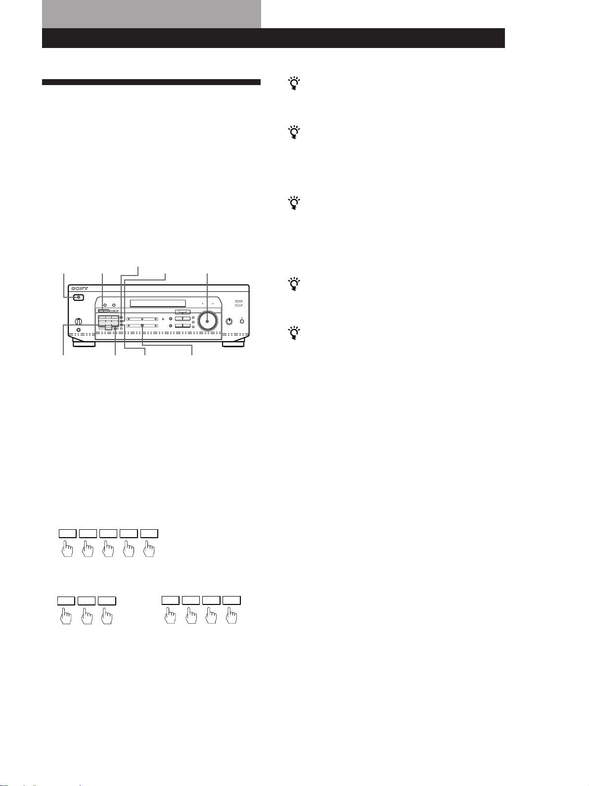
Page 17
Using Surround Sound
Enjoying Surround Sound
You can take advantage of surround sound simply by
selecting one of the pre-programed “sound fields” that
your receiver provides. You can enjoy the sound of a
movie theater or concert hall in your own home. You
can even customize a sound field by adjusting its
parameters.
Sound field are classified into three types.
Using Surround Sound
The third type is “MUSIC”. When a sound field in this
type is selected, the receiver adds the reverberation to
the normal 2-channel stereo sound. You can apply
these sound fields when playing a CD or watching TV
programs to obtain the surround effects of concert hall
or a jazz club.
To enjoy Dolby Pro Logic Surround sound fully, do the
procedure on “Dolby Surround Setup” starting from
page 10 to select the center mode and adjust the
speaker volume.
One type is “CINEMA”. The CINEMA type sound
fields are designed for enjoying movies recorded on
videos or laser discs. Four sound fields are included in
the CINEMA type and they are grouped into two
types. PRO LOGIC sound field can be used to
reproduce plain surround sound. When you select the
PRO LOGIC sound field, the receiver obtains full
surround sound by using Dolby Pro Logic to decode
Dolby Surround encoded software. The surround
sound is reproduced in the exact way that the sound
engineer of the software intended. Other sound fields
in the CINEMA type are designed to add more
reverberation effects by incorporating Digital Cinema
Sound technology. When you select these sound fields,
the receiver adds the reflection and reverberation
effects that are typical in movie theaters to the decoded
Dolby Pro Logic Surround sound. You can enjoy the
sound that you would experience in the movie theater.
Another type is “VIRTUAL”. Virtual mode allows you
to enjoy the surround sound environment using a
minimum of two front speakers to create non-existent
‘virtual’ speakers. The listener would be able to feel the
surround effects using only front speakers.
SOUND FIELD
MODE +/–
SUR
MENU </>
SOUND FIELD
ON/OFF
SET UP
+/–
ENTERBASS/TREBLE
TONE
17
US
Page 18

Using Surround Sound
Selecting a Sound Field
You can enjoy surround sound simply by selecting one
of the pre-programed sound fields according to the
program you want to listen to.
1 Press SOUND FIELD ON/OFF to turn on the
sound field.
The current sound field is indicated in the
display.
2 Press SOUND FIELD MODE +/– repeatedly to
select the sound field you want.
See the table on this page for information on each
sound field.
The receiver memorizes the last sound field selected
for each program source (Sound Field Link)
Whenever you select a program source, the sound field
that was last applied is automatically applied again. For
example, if you listen to CD with HALL as the sound
field, change to different program source, then return to
CD, HALL will be applied again. In the case of the
tuner, the sound fields for AM or FM band and for all
the preset stations are memorized separately.
You can identify Dolby Surround-encoded software
by looking at the packaging
Some videos and laser discs, however, may be encoded
with Dolby Surround sound even if it’s not indicated on
the package.
Note
When using sound fields, do not select both speakers (A+B)
with the SPEAKERS selector.
Description of sound fields
Type MODE (sound field) Effects
CINEMA PRO LOGIC Decodes programs
processed with Dolby
Pro Logic Surround.
C(inema) STUDIO Reproduces the sound
characteristics of a
movie theater. Good for
watching standard
movies.
N(ight) THEATER Adjust the tone for
watching a movie at
low volume at
nighttime.
MONO MOVIE Creates a theater-like
environment when
watching movies with
monaural soundtracks.
VIRTUAL V DOLBY Uses front speakers to
create surround sound
effects.
V SURROUND** Uses front speakers and
center speaker to create
surround sound effects.
MUSIC HALL Reproduces the
acoustics of a
rectangular concert
hall. Ideal for soft
acoustic sounds.
JAZZ CLUB Reproduces the
acoustics of a jazz club.
DISCO* Reproduces the
acoustics of a
discotheque.
CHURCH* Reproduces the
acoustics of a stone
church
LIVE HOUSE Reproduces the
acoustics of a 300-seat
live house.
STADIUM* Reproduces the feeling
of a large open-air
stadium. Great for
sporting events or
electric sounds.
GAME Obtains maximum
audio impact from
video game software.
Be sure to set the game
machine to stereo mode
for game software with
stereo sound capablity.
18
* STR-DE535 only.
** When using 5.1 CH/DVD only.
US
Page 19

Customizing Sound Fields
Using Surround Sound
Adjusting the volume of the rear and center
speakers (REAR/CENTER)
By adjusting some of the sound parameters, you can
customize sound fields to suit your particular listening
situation.
Once you customize a sound field, the changes are
stored in memory indefinitely (unless the receiver is
unplugged for about one week). You can change a
customized sound field any time by making new
adjustments to the parameters.
See the table on page 20 for adjustable parameters for
each sound field.
To get the most from Dolby Pro Logic
Surround sound
Do the procedures “Selecting the center mode” and
“Adjusting the speaker volume” on page 10 before you
customize a sound field.
Changing the delay time (DELAY) (PRO
LOGIC Sound Field only)
If you feel the volume of the rear or center speaker is
inadequate (even after adjusting the speaker volume
for Dolby Pro Logic Surround), do the procedure
below to adjust the volume.
Note that the speaker volume adjustment is applied to
all sound fields.
1 Press SUR.
2 Press MENU </> to select “REAR xxdB” or
“CENTER xxdB.”
3 Press +/– to adjust the speaker volume.
You can select a volume level of –15 dB to +10 dB
in 1-dB steps.
Adjusting the tone (BASS/TREBLE)
Adjust the tone (bass or treble) of the front speakers for
optimum sound. You can adjust the tone for each
separate sound field.
1 Press BASS/TREBLE.
You can enhance the Dolby Pro Logic Surround sound
even more by delaying the sound output from the rear
speakers (delay time). You can select a delay time of 15,
20, or 30 ms. Set a short delay time when the rear
speakers are located in a large room or far from where
you are listening.
1 Start playing a program source encoded with Dolby
Surround sound.
2 Press SUR.
3 Press MENU </> to select “DELAY xxms.”
The current delay time appears in the display.
4 Press +/– to change the delay time.
Changing the level of effect (EFFECT)
(all sound fields except PRO LOGIC)
You can specify the amount of the surround effect (i.e.,
its overall presence) in six levels.
1 Press SUR.
2 Press MENU </> to select “EFFECT xx.”
The current effect level appears in the display.
2 Press MENU </> to select “BASS xxdB” or
“TREBLE xxdB.”
3 Press +/– to adjust the tone level.
You can select a tone level of –10 dB to +10 dB in
2-dB steps.
4 Press TONE so that the TONE indicator lights up.
You can turn off the tone adjustments without
erasing them
The tone adjustments are stored separately for each
sound field. Press the TONE button to turn the TONE
indicator off.
Resetting customized sound fields to the
factory settings
1 If the power is on, press 1/u (power) to turn off
the power.
2 Hold down SOUND FIELD ON/OFF and press
1/u (power).
“SUR CLEAR” appears in the display and all
sound fields are reset at once.
3 Press +/– to change the effect level.
(continued)
19
US
Page 20

Using Surround Sound
Adjustable parameters for each sound field when selecting program source
Sound field mode
Off
On
Type
––
CINEMA
VIRTUAL
MUSIC
MODE
––
PRO LOGIC
C STUDIO
N THEATER
MONO MOVIE
V DOLBY
HALL
JAZZ CLUB
DISCO*
CHURCH*
LIVE HOUSE
STADIUM*
GAME
DELAY EFFECT REAR CENTER TONE
rr
Parameters
a)
rra)r
rr r
rr r
rr
rr r
rr r
rr r
rr r
rr r
rr r
rr r
b)
r
b)
Adjustable parameters for each sound field when using 5.1 CH/DVD
Sound field mode
Off
On
Type
––
CINEMA
VIRTUAL
MODE
––
C STUDIO
N THEATER
V SURROUND
DELAY EFFECT REAR CENTER TONE
Parameters
rrr
rr rr
rr rr
rrr
Test tone output
No sound
r
Depends on center mode (see
r
page 10)
r
From the front and the rear
speakers alternately
No sound
From the front and the rear
speakers alternately
Test tone output
In the following order:
front (L), center, front (R),
rear (R) and rear (L)
From the front and the center
speakers alternately
20
* STR-DE535 only
a) Adjustable only when the center mode is set to PHANTOM,
NORMAL or WIDE (see page 10).
b) Adjustable only when the center mode is set to 3 STEREO,
NORMAL or WIDE (see page 10).
Note
To adjust the speaker volume using a test tone as described
on page 10, select the PRO LOGIC sound field. The test tone
output in all other sound fields is used for verifying whether
there is output from speakers or not.
US
Page 21
Other Operations
Other Operations
Indexing Preset Stations and
Program Sources
You can enter a name of up to 8 characters for preset
stations (station index) and program sources. These
index names (for example, “VHS”) appear in the
receiver's display when a station or program source is
selected. This function is useful for distinguishing
components of the same kind. It is also handy for
identifying components connected to jacks meant for
another type of component, for example, a second CD
player connected to the MD/TAPE jacks.
Notes
• Not more than one name can be entered for each preset
station or program source.
• You cannot index components connected to the 5.1 CH/
DVD jacks.
1 To index a preset station.
Tune to the preset station you want to name.
To index a program source.
Select the program source (component) to be
named, then go to Step 2.
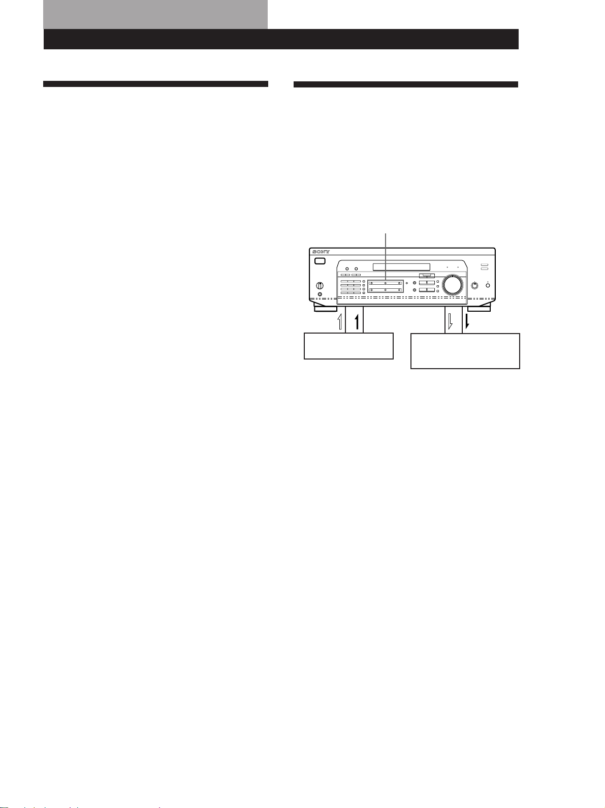
Recording
This receiver makes it easy to record to and from the
components connected to the receiver. You don’t have
to connect playback and recording components
directly: once you select a program source on the
receiver, you can record and edit as you normally
would using the controls on each component.
Before you begin, make sure you’ve connected all
components properly.
Function buttons
Playback component
(program source)
ç: Audio signal flow
c: Video signal flow
Recording component
(MD recorder, Tape deck,
VCR)
2 Press NAME.
The cursor blinks in the display.
3 Use + or – to select the character you desire.
4 Press MENU < or > to move the cursor into
position for the next character or previous
character.
5 Repeat Steps 3 and 4 to enter up to 8 characters.
6 Press ENTER to store the names.
If you make a mistake
Press MENU < or > repeatedly so that the character
you want to change blinks in the display, then use + or
– to select the desired character.
To assign index names to other stations
Repeat Steps 2 to 4.
To clear program source name
Press NAME and then press the same program source
button. Press ENTER to delete the name (except
TUNER).
Recording on a MiniDisc or audio tape
You can record on a MiniDisc or cassette tape using the
receiver. See the instruction manual of your MD
recorder or tape deck if you need help.
1 Press one of the function buttons to select the
program source.
2 Set the component to be ready for playing.
For example, insert a CD into the CD player.
3 Insert a blank disc or tape into the recording deck
and adjust the recording level, if necessary.
4 Start recording on the recording deck and then
start playing the component.
(continued)
21
US
Page 22
Other Operations
Recording on a video tape
You can record from a TV, a satellite receiver or a LD
player using the receiver. You can also add audio from
a variety of audio sources when editing a video tape.
See your VCR’s instruction manual if you need help.
1 Press TV/SAT (TV/LD) to select the program
source.
2 Set the component to be ready for playing.
For example, turn on the TV and TV tuner.
3 Insert a blank video tape into the VCR for
recording.
4 Start recording on the VCR.
You can replace audio while editing a video tape
At the point you want to start adding different sound,
press another function button (for example, CD) and
start playback. The sound from the selected component
will be recorded over the original audio.
To resume recording the original sound, press the
TV/SAT (TV/LD) function button.
Note
You cannot record the audio and video signal during
5.1 CH/DVD mode.
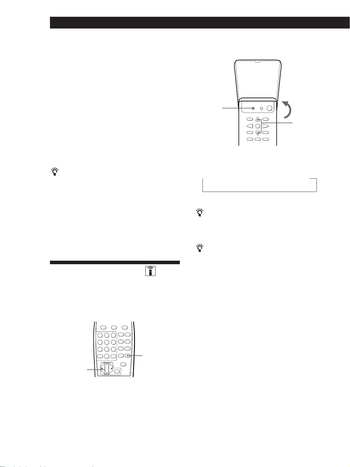
Using the Sleep Timer
STR-DE435 only
SLEEP
>/.
Press SLEEP on the remote while the power is on.
Each time you press SLEEP, the time changes as shown
below.
n 2:00:00 n 1:30:00 n 1:00:00 n 0:30:00 n OFF
The display dims after you specify the time.
You can freely specify the time
Press SLEEP on the remote first, then specify the time
you want using the cursor buttons (> or .).
The sleep time changes in 1 minute intervals. You can
specify up to 5 hours.
You can check the time remaining before the
amplifier turns off
Press SLEEP on the remote. The remaining time appears
in the display.
22
Using the controls on the remote, you can set the
amplifier to turn off automatically at a time you
specify.
STR-DE535 only
SLEEP
>/.
US
Page 23

Adjustments Using the SET UP
Button
The SET UP button allows you to make the following
adjustments.
Adjusting the Control A1 II auto function
Turning on the Control A1 II auto function parameter
lets you to turn Sony components connected via
Control A1 II cords (see page 6) on automatically when
you press the corresponding function button.
Auto function is set to ON by default.
Other Operations
Setting up the 2 way remote
This receiver is shipped from the factory with the 2
way remote control system set to “ON”. Normally, you
can use the receiver as is.
However, if you want to use this receiver together with
another component that is also compatible with the 2
way remote control system, be sure to perform the
following operation to limit response to signals sent
from the remote controls.
To use with the TA-E9000ES
Perform the following steps to turn OFF this unit’s 2
way remote control system. Also, be sure the TAE9000ES is turned on when using this unit.
1 Press SET UP.
2 Press MENU </> to select “AUTO FUNCTION”.
3 Press +/– to select “A-FUNC ON” or “A-FUNC
OFF”.
To use with other components that have the
logo
Turn OFF the other component’s 2 way remote control
system. For details, refer to the operating instructions
supplied with your other components.
To use with CD players CDP-CX260 or CDP-CX88ES
Turn OFF the remote control adaptor switch on the
CDP-CX260 or CDP-CX88ES. For details, refer to the
operating instructions supplied with the CDP-CX260
or CDP-CX88ES.
Also when using several 2 way remote control system
components together, be sure to place them close
together in order to enable proper remote operation.
1 Press SET UP.
2 Press MENU </> to select “2WAY SETUP”.
3 Press +/– to select “2WAY ON” or “2WAY OFF”.
23
US
Page 24

Additional Information
Troubleshooting
If you experience any of the following difficulties while
using the receiver, use this troubleshooting guide to
help you remedy the problem. Should any problem
persist, consult your nearest Sony dealer.
There’s no sound or only a very low-level sound is heard.
/ Check that the speakers and components are
connected securely.
/ Make sure you select the correct component
on the receiver.
/ Make sure you set the SPEAKERS selector
correctly (see page 12).
/ Press MUTING or MUTING on the remote if
the MUTING indicator turns on.
/ The protective device on the receiver has been
activated because of a short circuit
(“PROTECTOR” flashes). Turn off the
receiver, eliminate the short-circuit problem
and turn on the power again.
Radio stations cannot be tuned in.
/ Check that the antennas are connected
securely. Adjust the antennas and connect an
outdoor antenna if necessary.
/ The signal strength of the stations is too weak
(when you tune in with automatic tuning).
Use direct tuning.
/ Make sure you set the tuning interval
correctly (when you tune in AM stations with
automatic tuning) (see pages 15 and 25).
/ No stations have been preset or the preset
stations have been cleared (when you tune in
with scanning preset stations). Preset the
stations (see page 16).
Surround effect cannot be obtained.
/ Make sure you turn on the sound field
function.
/ Make sure that the front speakers are
connected to the SPEAKERS A terminal.
/ Make sure that SPEAKERS A and B buttons
are depressed when two sets of front speakers
are used.
The left and right sounds are unbalanced or reversed.
/ Check that the speakers and components are
connected correctly and securely.
/ Adjust the BALANCE control.
Severe hum or noise is heard.
/ Check that the speakers and components are
connected securely.
/ Check that the connecting cords are away
from a transformer or motor, and at least 10
feet (3 meters) away from a TV set or
fluorescent light.
/ Place your TV away from the audio
components.
/ Make sure you connect a ground wire to the
antenna ground terminal.
/ The plugs and jacks are dirty. Wipe them
with a cloth slightly moistened with alcohol.
No sound is heard from the center speaker.
/ Select the appropriate center mode (see page
10).
/ Adjust the speaker volume appropriately (see
page 10).
No picture or an unclear picture is seen on the TV screen.
/ Select the appropriate function on the
receiver.
/ Place your TV away from the audio
components.
Recording cannot be made.
/ Check that the components are connected
correctly.
/ You cannot record audio from a program
source connected to the 5.1 CH/DVD jacks.
The remote does not function.
/ Point the remote at the remote sensor
(STR-DE535) or g (STR-DE435) on the
receiver.
/ Remove the obstacles in the path of the
remote and the receiver.
/ Replace both batteries in the remote with new
ones if they are weak.
/ Make sure you select the correct function on
the remote.
24
No sound or only a very low-level sound is heard from
the rear speakers.
/ Select the appropriate center mode (see page
10).
/ Adjust the speaker volume appropriately (see
page 10).
/ Make sure you turn on the sound field
US
Page 25

Additional Information
Specifications
Amplifier section
Power output
Stereo mode
Surround mode
and 5.1 CH/DVD
(Reference)
Frequency
response
Canada model:
(8 ohms 20 Hz - 20 kHz,
less than 0.09% total
harmonic distortion)
100 W + 100 W
Australia, Singapore,
Malaysia and other
countries models:
Rated power: (8 ohms at
1 kHz, THD 0.7%)
100 W + 100 W
Reference power: (8 ohms
20 Hz - 20 kHz, less
than 0.09% total
harmonic distortion)
95 W + 95 W
Canada model:
(8 ohms at 1 kHz, THD
0.8%)
Front: 100 W/ch
Center*: (ProLogic mode)
100 W
Rear*: 100 W/ch
Australia, Singapore,
Malaysia and other
countries models:
Rated power: (8 ohms at 1
kHz, THD 0.7%)
Front: 100 W/ch
Center*: (ProLogic mode)
100 W
Rear*: 100 W/ch
Reference power: (8 ohms
20 Hz - 20 kHz, less
than 0.09% total
harmonic distortion)
Front: 95 W/ch
Center*: (ProLogic mode)
95 W
Rear*: 95 W/ch
RMS power: (8 ohms at
1 kHz, THD 10%)
Front: 135 W/ch
Center*: (ProLogic mode)
135 W
Rear*: 135 W/ch
PHONO: RIAA
equalization curve
±0.5 dB
(STR-DE535 only)
TV/SAT (TV/LD), CD,
MD/TAPE, VIDEO,
5.1 CH/DVD:
10 Hz - 50 kHz ±1 dB
Inputs
PHONO
(STR-DE535
only)
Sensitivity
4 mV
Impedance
50
kilohms
86 dB
CD, 5.1 CH/
DVD, MD/
TAPE, TV/
SAT (TV/
250 mV
50
kilohms
96 dB
LD), VIDEO
Outputs
Muting
BASS BOOST
TONE
MD/TAPE REC OUT:
Voltage: 250 mV,
Impedance: 10 kilohms
VIDEO AUDIO OUT:
Voltage: 250 mV,
Impedance: 10 kilohms
WOOFER:
Voltage: 2 V
Impedance: 1 kilohms
PHONES: Accepts low
and high impedance
headphones
Full mute
+8 dB at 70 Hz
±8 dB at 100 Hz and
10 kHz
Tuner section
FM stereo, FM/AM superheterodyne tuner
FM tuner section
Tuning range
Antenna terminals
Intermediate
frequency
Sensitivity
Usable sensitivity
S/N
Harmonic
distortion at
1 kHz
Separation
Frequency
response
Selectivity
87.5 - 108.0 MHz
75 ohms, unbalanced
10.7 MHz
Mono: 18.3 dBf, 4.5 µV
Stereo: 38.3 dBf, 45 µV
11.2 dBf, 1 µV (IHF)
Mono: 76 dB
Stereo: 70 dB
Mono: 0.3 %
Stereo: 0.5 %
45 dB at 1 kHz
30 Hz - 15 kHz dB
60 dB at 400 kHz
+0.5
–2
AM tuner section
Tuning range
Australia, Singapore and
Malaysia models:
531 - 1602 kHz (9 kHz
step)
Canada model:
530 - 1710 kHz (10 kHz
step)
531 - 1710 kHz (9 kHz
step)
S/N
Antenna
Intermediate
frequency
Usable sensitivity
S/N
Harmonic
distortion
Selectivity
You can change the AM tuning interval to
10 kHz (except Australia, Singapore and
Malaysia model). After tuning in any AM
station, turn off the receiver. Hold down the
PRESET TUNING + button and press the
1/u (power) button. All preset stations will
be erased when you change the interval. To
reset the interval to 9 kHz, repeat the same
procedure.
Loop antenna
450 kHz
50 dB/m (at 999 kHz)
54 dB (at 50 mV/m)
0.5 % (50 mV/m, 400 Hz)
At 9 kHz: 35 dB
At 10 kHz: 40 dB
Video section
Inputs
Output
VIDEO, TV/SAT (TV/
LD), 5.1 CH/DVD:
1 Vp-p 75 ohms
VIDEO, MONITOR:
1 Vp-p 75 ohms
General
System
Power
requirements
Power
consumption
Tuner section: PLL
quartz-locked digital
synthesizer system
Preamplifier section:
Low-noise NF type
equalizer
Power amplifier section:
Pure-complementary
SEPP
Canada model:
120 V AC, 60 Hz
Australia model:
240 V AC, 50 Hz
Singapore and Malaysia
models:
230 V AC, 50/60 Hz
Other countries:
120/220/240 V AC,
50/60 Hz
Canada Model:
300 VA
Australia, Singapore and
Malaysia models:
195 W
Other countries models:
245 W
Other countries models:
530 - 1610 kHz (10 kHz
step)
531 - 1602 kHz (9 kHz
step)
(continued)
25
US
Page 26
Additional Information
AC outlets
Canada Model:
STR-DE435:
1 switched 120 W/1A
max
STR-DE535:
2 switched 120 W/1A
max
Australia, Singapore and
Malaysia models:
1 switched 100 W max
Other countries models :
2 switched 100 W max
Dimensions
Mass (Approx.)
430 x 157 x 366 mm
STR-DE535:
11.4 kg (25 lb 1 oz)
STR-DE435:
10.8 kg (23 lb 12 oz)
Supplied
See page 4
accessories
The specification measured is under
• 230 V AC, 50 Hz condition (Singapore
and Malaysia models).
• 240 V AC 50 Hz condition (Australia
model).
* Depending on the sound field setting
and the source, there may be no sound
output.
Design and specifications are subject to
change without notice.
Glossary
Surround sound
Sound that consists of three elements: direct
sound, early reflected sound (early
reflections) and reverberative sound
(reverberation). The acoustics where you hear
the sound affect the way these three sound
elements are heard. These sound elements are
combined in such a way that you can actually
feel the size and the type of a concert hall.
• Types of sound
Early reflections
Direct sound
Reverberation
Dolby Pro Logic Surround
As one method of decoding Dolby Surround,
Dolby Pro Logic Surround produces four
channels from two-channel sound. Compared
with the former Dolby Surround system,
Dolby Pro Logic Surround reproduces left-toright panning more naturally and localizes
sounds more precisely. To take full
advantage of Dolby Pro Logic Surround, you
should have one pair of rear speakers and a
center speaker. The rear speakers output
monaural sound.
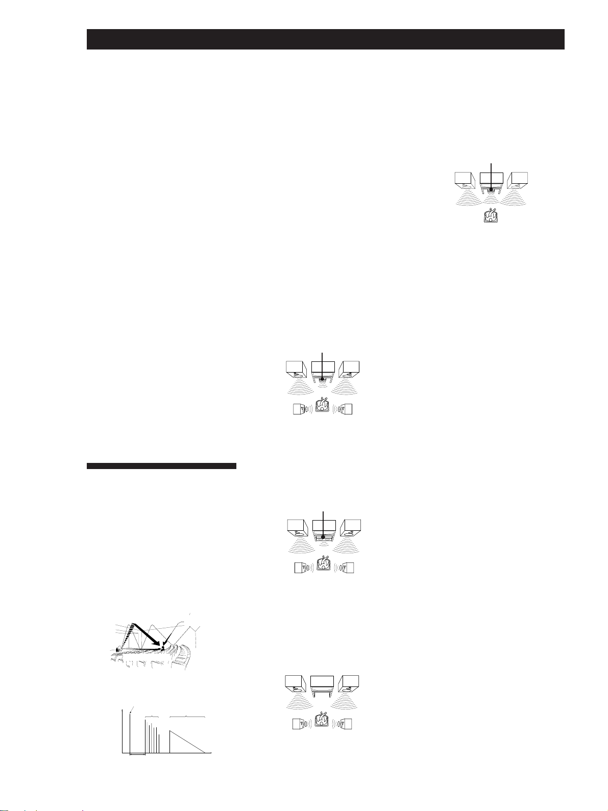
Center mode
Setting of speakers to enhance Dolby Pro
Logic Surround mode. To obtain the best
possible surround sound, select one of the
following four center modes according to
your speaker system.
• NORMAL mode
Select NORMAL mode if you have front
and rear speakers and a small center
speaker. Since a small speaker cannot
produce enough bass, the bass sound of
the center channel is output from the front
speakers.
Front
speaker (L)
Rear
speaker (L)
Center
speaker
Front
speaker (R)
Rear
speaker (R)
• WIDE mode
Select WIDE mode if you have front and
rear speakers and a large center speaker.
With the WIDE mode, you can take full
advantage of Dolby Surround sound.
Front
speaker (L)
Rear
speaker (L)
Center
speaker
Front
speaker (R)
Rear
speaker (R)
• PHANTOM mode
Select PHANTOM mode if you have front
and rear speakers but no center speaker.
The sound of the center channel is output
from the front speakers.
Front
speaker (L)
Front
speaker (R)
• 3 STEREO mode
Select 3 STEREO mode if you have front
and center speakers but no rear speaker.
The sound of the rear channel is output
from the front speakers to let you
experience some of the surround sound
without using rear speakers.
Front
speaker (L)
Center
speaker
Front
speaker (R)
Delay time
Time lag between the surround sound output
from front speakers and rear speakers. By
adjusting the delay time of the rear speakers,
you can obtain the feeling of presence. Make
the delay time longer when you have placed
the rear speakers in a small room or close to
your listening position, and make it shorter
when you have placed them in a large room
or apart from your listening position.
Dolby Digital (AC-3)
This sound format for movie theaters is more
advanced than Dolby Pro Logic Surround. In
this format, the rear speakers output stereo
sound with an expanded frequency range
and a subwoofer channel for deep bass is
independently provided. This format is also
called “5.1” because the subwoofer channel is
counted as 0.1 channel (since it functions only
when a deep bass effect is needed). All six
channels in this format are recorded
separately to realize superior channel
separation. Furthermore, since all the signals
are processed digitally, less signal
degradation occurs. The name “AC-3” comes
from the fact that it is the third audio coding
method to be developed by the Dolby
Laboratories Licensing Corporation.
5.1 CH/DVD jacks
These jacks are used to input decoded Dolby
Digital (AC-3) audio signals, allowing you to
enjoy 5.1 channel surround sound. Use these
jacks to connect a Dolby Digital (AC-3)
decoder or a DVD player with a built-in AC-3
decoder.
Preset station
A radio broadcasting station that is stored in
memory of the receiver. Once you “preset”
stations, you no longer have to tune in the
stations. Each preset station is assigned its
own preset number, which lets you tune
them in quickly.
26
US
• Transition of sound from rear speakers
Direct sound
Level
Early reflection time
Early
reflections
Reverberation
Time
Rear
speaker (L)
Rear
speaker (R)
Page 27

Index
A, B
Adjusting
brightness of the display 9
delay time 19, 25
effect level 19
speaker volume 10
tone 19
volume 12
Antenna hookups 5
Audio component hookups 5,
6
Automatic tuning 15
C
Center mode 10, 26
NORMAL mode 10, 26
PHANTOM mode 10, 26
3 STEREO mode 10, 26
WIDE mode 10, 26
Connecting. See Hookups
D
Delay time 19, 25
Direct tuning 15
Dolby Pro Logic
Surround 10, 17
center mode 10, 26
Dubbing. See Recording
E, F, G
Editing. See Recording
Effect level 19
H, I, J, K, L, M
Hookups
AC power cord 9
antennas 5
audio components 5, 6
overview 4
speakers 7, 8
video component 6, 7
Indexing preset stations and
program sources 21
N, O
NORMAL mode 10, 26
P
PHANTOM mode 10, 26
Preset station 16
Presetting
radio stations 16
Preset tuning 16
Q
Quick reference guide 29
R
Rear panel 5, 6, 7, 9, 28
Receiving broadcasts
directly 15
using preset stations 16
Recording
on a minidisc 21
on a tape 21
on a video tape 22
S
Scanning
preset stations 16
radio stations 16
Sleep Timer 22
Sound field
customizing 19
selecting 18
Speakers
connection 7, 8
placement 10
selecting speaker system 12
Storing radio stations. See
Presetting
Surround sound 17
T
Test tone 10
3 STEREO mode 10, 26
Troubleshooting 24
Tuning. See Receiving
broadcasts
U
Unpacking 4
V
Video component hookups 6,
7
W, X, Y, Z
WIDE mode 10, 26
27
US
Page 28

Rear Panel Descriptions
1
2 34 5 6 7 !¶ !§!•
1 ANTENNA (AM and FM)
2 y ground terminal
(STR-DE535 only)
3 PHONO (STR-DE535 only)
4 CD
5 MD/TAPE
6 TV/SAT (TV/LD)
7 VIDEO
8 9 !™ !£ !¢!¡!º
8 5.1 CH/DVD
9 MONITOR
!º CTRL A1 II (STR-DE535 only)
!¡ WOOFER
(STR-DE535 - 2 pins,
STR-DE435 - 1 pin)
!™ SPEAKERS REAR
!£ SPEAKERS CENTER
!∞
!¢ VOLTAGE SELECTOR (except
Canada, Australia, Singapore
and Malaysia)
!∞ AC power cord
!§ SWITCHED AC OUTLET
!¶ SPEAKERS FRONT (A/B)
!• IMPEDANCE SELECTOR
28
US
Page 29

Quick Reference Guide
Receiving Broadcasts
(direct tuning)
Example: Receiving FM
102.50 MHz
TUNER
FM
Select FM.
DIRECT
10250
Display
MHz
Presetting Radio
Stations
Example: Presetting a
station as A7
TUNER
Tune in the station you want.
MEMORY
SHIFT
Select A.
7
Selecting a
Component
Example 1:Playing a CD
CD
Turn on the CD player.
Start playing.
Example 2:Watching a video
tape
VIDEO
Turn on the VCR.
Start playing.
Scanning Radio
Stations
Example: Scanning FM
(automatic tuning)
stations
TUNER
FM
Select FM.
—+
TUNING
To continue
scanning.
—+
TUNING
Receiving Preset
Stations
Example: Receiving the
station number A7
TUNER
SHIFT
Select A.
7
Scanning Preset
Stations
TUNER
Using Pre-programmed
Sound Fields
Example: Watching the
video tape of a
Dolby Surroundencoded movie
VIDEO
SOUND FIELD
ON/OFF
SOUND FIELD
—
MODE
Turn on the VCR.
Start playing.
+
MODE
Select
C.STUDIO
—
PRESET
TUNING
+
US
29
Page 30

Préparatifs
AVERTISSEMENT
Afin d’éviter tout risque
d’incendie ou
d’électrocution, éviter
d’exposer l’appareil à la
pluie ou à l’humidité.
Afin d’écarter tout risque
d’électrocution, garder le coffret fermé.
Ne confier l’entretien de l’appareil qu’à
un personnel qualifié.
N’installez pas l’appareil dans un
espace exigu, comme dans une
bibliothèque ou renfermé dans un
boîtier.
Pour les clients au Canada
ATTENTION:
POUR PREVENIR LES CHOCS
ELECTRIQUES, NE PAS UTILISER
CETTE FICHE POLARISEE AVEC UN
PROLONGATEUR, UNE PRISE DE
COURANT OU UNE AUTRE SORTIE
DE COURANT, SAUF SI LES LAMES
PEUVENT ETRE INSEREES A FOND
SANS EN LAISSER AUCUNE PARTIE
A DECOUVERT.
Précautions
Sécurité
• Si un solide ou un liquide tombait
dans le coffret, débranchez l’amplituner et faites le vérifier par un
technicien qualifié avant de le
remettre en service.
Sources d’alimentation
• Avant de mettre en service l’amplituner, vérifiez que la tension de
fonctionnement correspond à celle du
courant secteur local. La tension de
fonctionnement est indiquée sur la
plaque signalétique à l’arrière de
l’ampli-tuner.
• L’ampli-tuner n’est pas déconnecté de
la source d’alimentation (secteur) tant
qu’il est branché sur une prise
murale, même si vous le mettez hors
tension.
• Si vous ne comptez pas utiliser
l’ampli-tuner pendant un certain
temps, débranchez-le de la prise
murale. Pour débrancher le cordon,
tirez sur la fiche et jamais sur le
cordon proprement dit.
• Si le cordon d’alimentation secteur
doit être remplacé, adressez-vous à
un technicien qualifié uniquement.
Fonctionnement
• Avant de raccorder d’autres
appareils, mettez l’ampli-tuner hors
tension et débranchez-le.
Nettoyage
• Nettoyez le coffret, le panneau et les
commandes avec un chiffon doux
légèrement imprégné d’une solution
détergente douce. N’utilisez pas de
tampon abrasif, poudre à récurer ou
solvant, comme de l’alcool ou de la
benzine.
En cas de question ou de problème
concernant l’ampli-tuner, consultez
le revendeur Sony le plus proche.
Installation
• Installez l’ampli-tuner dans un
endroit bien ventilé pour éviter tout
risque de surchauffe interne et
prolonger la durée de vie des
composants.
• N’installez pas l’ampli-tuner près
d’une source de chaleur, dans un
endroit en plein soleil, poussiéreux
ou exposé à des chocs mécaniques.
• Ne posez rien sur le coffret qui puisse
bloquer les orifices de ventilation et
provoquer un mauvais
fonctionnement.
FR
2
Page 31

Préparatifs
Au sujet de ce
manuel
Les instructions de ce mode d’emploi
sont destinées aux modèles STR-DE535
et STR-DE435. Vérifiez le numéro de
votre modèle dans le coin supérieur
droit de la façade. Dans ce mode
d’emploi, les illustrations représentent
le STR-DE535. Toute différence de
fonctionnement avec les autres modèles
est clairement indiquée dans le texte,
par exemple, “STR-DE535 seulement”.
Différence entre les modèles
Modéle
Caractéristique
PHONO
CONTROL A1 II
Conventions
Ce mode d’emploi décrit le
fonctionnement avec les commandes de
l’ampli-tuner. Vous pouvez également
utiliser les commandes de la
télécommande qui ont un nom
identique ou similaire à celles de
l’ampli-tuner. Pour les détails sur
l’utilisation de la télécommande,
reportez-vous au mode d’emploi séparé
de la télécommande.
• Vous trouverez un “Guide de
référence rapide” page 29.
• Les icônes suivants sont utilisés dans
ce manuel:
Indique que vous pouvez utiliser
la télécommande pour effectuer
cette opération.
Donne des conseils
supplémentaires pour faciliter
l’utilisation.
•
•
DE435DE535
TABLE DES MA TIÈRES
Préparatifs
Déballage 4
Description des raccordements 4
Raccordement d’antennes 5
Raccordement de composants audio 5
Raccordement de composants vidéo 6
Raccordement d’enceintes 7
Raccordement au courant secteur 9
Avant la mise en service de l’ampli-tuner 9
Configuration du Dolby Surround 10
Nomenclature et opérations élémentaires de l’amplificateur
Description des éléments du panneau avant 12
Fonctionnement de l’ampli-tuner
Réception radio 15
Préréglage des stations de radio 16
Ecoute de son surround
Utilisation de son Surround 17
Sélection d’un champ sonore 18
Personnalisation des champ sonores 19
Autres operations
Indexation des stations préréglées et des sources de programme 21
Enregistrement 21
Utilisation du programmateur d’extinction 22
Réglages à l’aide de la touche SET UP 23
Informations supplémentaires
Guide de dépannage 24
Spécifications 25
Glossaire 26
Index 27
EN
FR
E
Ce récepteur intègre un décodeur Dolby
Pro Logic Surround.
Fabriqué sous licence de Dolby
Laboratories Licensing Corporation
DOLBY, le symbole double-D a et
PRO LOGIC sont des marques de Dolby
Laboratories Licensing Corporation.
Nomenclature du panneau arrière 28
Guide de référence rapide 29
FR
3
Page 32

Préparatifs
Déballage
Vérifiez si les accessoires suivants se trouvent dans
l’emballage.
• Antenne fil FM (1)
• Antenne cadre AM (1)
• Télécommande (1)
Modèle Télécommande
STR-DE535 RM-LJ302
STR-DE435 RM-PP402
• Piles LR6 (format AA) (3) (STR-DE535 uniquement)
• Piles R6 (format AA) (2) (STR-DE435 uniquement)
• Mode d’emploi de le télécommande
• Mode d’emploi de le CONTROL A1 II (1)
(STR-DE535 uniquement)
Mise en place des piles dans la
télécommande
Insérez les piles LR6 (STR-DE535) ou R6 (STR-DE435)
(format AA) en faisant correspondre les bornes + et –
avec le schéma dans le logement. Pour utiliser la
télécommande, dirigez-la vers le détecteur infrarouge
(STR-DE535) ou g (STR-DE435) sur l’ampli-tuner.
Pour les détails, reportez-vous au mode d’emploi
fourni avec la télécommande.
Description des raccordements
Vous pouvez raccorder les composants audio/vidéo
suivants à l’ampli-tuner. Selon les composants que
vous voulez raccorder, reportez-vous aux pages
indiquées pour les démarches à suivre. Pour plus de
détails sur les différentes prises de l’ampli-tuner,
reportez-vous à “Nomenclature du panneau arrière”
page 28.
Raccordement
d’enceintes
(7)
Enceinte
avant
(gauche)
Raccordement
de composants
vidéo (6)
Moniteur TV
Tuner TV
SAT (récepteur
Satellite)/
lecteur LD
Magnétoscope
Lecteur DVD/
décodeur AC-3
Raccordement
d’antennes (5)
Antenne FM/AM
Enceinte
avant
(droite)
Vous ne pouvez pas utiliser les touches suivantes de
la télécommande RM-PP402
• VIDEO2
• VIDEO3
• DVD
• PHONO
• SOUND FIELD A.F.D.
Remarques
• Ne laissez pas la télécommande dans un endroit
extrêmement chaud ou humide.
• N’insérez pas une pile neuve avec une vieille pile.
• N’exposez le détecteur infrarouge aux rayons directs du
soleil ou à un dispositif d’éclairage car cela pourrait
provoquer un mauvais fonctionnement.
• Si vous prévoyez de ne pas utiliser la télécommande
pendant longtemps, enlevez les piles pour éviter tout
dommage dû à une fuite d’électrolyte et à la corrosion.
Caisson
de grave
amplifié
Enceinte
arrière
(droite)
Enceinte
arrière
(gauche)
Lecteur CD
Platine à
MD/cassette
Tourne-disque
(STR-DE535
uniquement)
Raccordement de
composants audio (5)
Enceinte
centrale
Avant de commencer
• Mettez tous les composants hors tension avant
d’effectuer les connexions.
• Effectuez toutes les connexions avant de brancher le
cordon d’alimentation secteur.
• Enfoncez les fiches correctement pour éviter un
bourdonnement et du bruit.
• Lors du raccordement d’un cordon audio/vidéo,
faites correspondre les broches codées par couleur
aux prises sur les composants: jaune (vidéo) à jaune,
blanc (audio, gauche) à blanc et rouge (audio, droit)
à rouge.
FR
4
Page 33

Raccordement d’antennes
Aperçu
Préparatifs
Si la réception AM est de mauvaise qualité
Raccordez un fil isolé de 6 à 15 mètres (non fourni) à la
borne d’antenne AM en plus de l’antenne cadre AM.
Essayez de dérouler le fil à l’extérieur et de le conserver
à l’horizontale.
Ce paragraphe explique comment raccorder des
antennes AM et FM à l’ampli-tuner. Si vous voulez
écouter la radio via l’ampli-tuner, effectuez ces
connexions en premier lieu, puis passez aux pages
suivantes. L’illustration ci-dessous indique
l’emplacement des bornes sur l’ampli-tuner.
y (STR-DE535
uniquement)
ANTENNA
De quelles antennes avez-vous besoin?
• Antenne fil FM (fournie)
(1)
• Antenne cadre AM
(fournie) (1)
Raccordement du fil de terre
Si vous raccordez l’ampli-tuner à une antenne
extérieure, veillez à la mettre à la terre, comme indiqué
sur l’illustration de gauche, par mesure de protection
contre la foudre. Afin d’éviter tout risque d’explosion,
ne raccordez pas le fil de terre à un tuyau de gaz.
Remarque (except STR-DE435)
N’utilisez pas la borne SIGNAL GND y pour mettre le
récepteur à la terre.
Que faire ensuite?
Si vous voulez raccorder d’autres composants, passez au
paragraphe suivant. Si vous comptez utiliser l’ampli-tuner
uniquement pour écouter la radio, allez directement à
“Raccordement d’enceintes” pages 7 et 8.
Raccordement de composants
audio
Raccordements
Antenne fil FM
Après avoir
raccordé
l‘antenne fil,
étendez le fil si
possible à
l’horizontale.
Si la réception FM est de mauvaise qualité
Raccordez un câble coaxial de 75-ohms (non fourni)
pour raccorder l’ampli-tuner à une antenne FM
extérieure, comme indiqué ci-dessous.
Fil de terre
(non fourni)
Récepteur
ANTENNA
AM
y
COAXIAL
FM
75Ω
Récepteur
ANTENNA
AM
y
COAXIAL
FM
75Ω
Antenne cadre AM
Antenne
extérieure FM
Aperçu
Ce paragraphe explique comment raccorder des
composants audio à l’ampli-tuner. Si vous souhaitez
utiliser l’ampli-tuner comme amplificateur, effectuez
ces connexions. L’illustration ci-dessous indique
l’emplacement des prises.
y (STR-DE535
uniquement)
PHONO (STR-DE535
uniquement)
De quels cordons avez-vous besoin?
Vous avez besoin de cordons audio (non fournis) (1 pour le
lecteur CD ou le tourne-disque et 2 pour la platine MD ou le
lecteur de cassette).
Blanc (gauche)
CTRL A1 II (STR-DE535 uniquement)
CD MD/TAPE
Blanc (gauche)
Rouge (droit)Rouge (droit)
vers la terre
(continuer page suivante)
FR
5
Page 34

Préparatifs
Raccordements
La flèche ç indique le sens du signal.
Lecteur CD
Raccordement de composants
vidéo
Ampli-tuner
L
R
AUDIO IN
CD
Lecteur CD
OUTPUT
LINE
L
R
Tourne-disque (STR-DE535 uniquement)
Ampli-tuner
L
R
AUDIO IN
PHONO
Tourne-disque
OUTPUT
LINE
L
R
• Si le tourne-disque est équitpé d’un fil de terre
Reccordez le fil de terre à la borne y sur l’ampli-tuner
pour éviter tout bourdonnement.
Platine MD ou platine à cassette
Ampli-tuner
IN
REC OUT
MD/TAPE
L
R
Platine MD ou
platine à cassette
OUTPUT
INPUT
LINE
LINE
Aperçu
Ce paragraphe explique comment raccorder des
composants vidéo à l’ampli-tuner. L’illustration cidessous indique l’emplacement des prises.
5.1 CH/DVD
(TV/LD)
De quels cordons avez-vous besoin?
• Vous avez besoin de cordons audio/vidéo (non fournis) (1
pour le téléviseur, récepteur Satellite ou lecteur LD et 2
pour le magnétoscope).
Jaune
Blanc (G)
Rouge (R)
L
R
• Vous avez besoin également d’un cordon vidéo (non
fourni) (1 pour le moniteur TV).
MONITOR
VIDEOTV/SAT
Jaune
Blanc (G)
Rouge (D)
JauneJaune
CONTROL A1 II (STR-DE535 uniquement)
Lecteur CD, platine à
Ampli-tuner
CTRL
A1 II
cassette ou platine MD
CTRL
A1 II
Si vous avez un lecteur CD, une platine à cassette ou une
platine MD Sony, compatible avec le système CONTROL
A1 II
Utilisez un cordon CONTROL A1 II (non fourni) pour relier
la prise CTRL A1 II du lecteur CD, de la platine à cassette ou
de la platine MD à la prise CTRL A1 II de l’ampli-tuner.
Consultez le manuel séparé “Système de commande
CONTROL-A1 II” et le mode d’emploi fourni avec le lecteur
CD, la platine à cassette ou la platine MD pour les détails.
Que faire ensuite?
Passez à la section suivante pour raccorder des composants
vidéo afin d’exploiter le son spatial pendant que vous
regardez/écoutez des émissions de télévision ou des
enregistrements vidéo.
FR
6
La flèche ç indique le sens du signal.
TV/SAT (TV/LD)
Ampli-tuner
VIDEO IN
AUDIO IN
TV/LD
Tuner TV ou récepteur
Satellite ou lecteur LD
L
R
OUTPUT
VIDEO
AUDIO
L
R
Moniteur
Ampli-tuner
MONITOR
VIDEO
OUT
Moniteur TV
INPUT
VIDEO
Raccordements
Page 35

Magnétoscope
Ampli-tuner Magnétoscope
VIDEO IN
VIDEO OUT
L
R
AUDIO IN
AUDIO OUT
VIDEO
Utilisez les touches de fonction (TV/SAT (TV/LD), CD,
MD/TAPE etc) pour sélectionner le signal VIDEO
AUDIO OUT. Vous pouvez enregistrer ce signal audio
en raccordant un appareil enregistreur tel qu’une
platine à cassette (à la prise VIDEO AUDIO OUT).
OUTPUT
VIDEO
AUDIO
INPUT
VIDEO
AUDIO
L
R
Lecteur DVD/décodeur AC-3
De quels cordons avez-vous besoin?
• Cordons audio (non fournis) (1 pour les prises 5.1 CH/
DVD FRONT et REAR)
Blanc (G)
Rouge (D)
• Cordons audio monophoniques (non fournis) (1 pour les
prises 5.1 CH/DVD CENTER et WOOFER)
Noir Noir
• Cordon vidéo (non fourni) (1 pour les prises 5.1 CH/DVD
VIDEO IN)
Jaune
Blanc (G)
Rouge (D)
Jaune
Préparatifs
Raccordement d’enceintes
Aperçu
Ce paragraphe explique comment raccorder des
enceintes à l’ampli-tuner. Pour bénéficier des effets
d’ambiance, des haut-parleurs central et arrière et un
haut-parleur d’extrêmes-graves actif sont
indispensables. L’illustration ci-dessous indique
l’emplacement des bornes sur l’ampli-tuner.
WOOFER
IMPEDANCE
SELECTOR
REAR
SPEAKERS
FRONT B
De quels cordons avez-vous besoin?
Vous avez besoin de cordons d’enceintes (non fournis) (1
pour chaque enceinte).
(–)
Dénudez environ 15 mm de gaine à chaque extrémité du
cordon. Veillez à faire correspondre les bornes des cordons
d’enceintes aux bornes des composants: + à + et – à –. Si les
cordons sont inversés, le son risque de présenter de la
distorsion et de manquer de graves.
SPEAKERS
SPEAKERS
CENTER
SPEAKERS
FRONT A
(+)(+)
(–)
Le son Dolby Digital AC-3 décode peut être
reproduit par les enceintres raccordées
l'amplificateur.
Si vous disposez d'un décodeur Dolby Digital AC-3, les
raccordements suivants vous permettent d'amplifier un
enregistrement Dolby Digitl AC-3 décodé.
Dolby Digital AC-3
Ampli-tuner
5.1 CH / DVD
FRONT FRONTREAR REARCENTER
L
R
WOOFER
VIDEO
VIDEO IN
décodeur, etc.
PRE OUT
CENTER
WOOFER
Que faire ensuite?
Passez au paragraphe suivant pour le raccordement des enceintes.
Raccordements
Enceintes avant
Enceinte avant
(droite)
Ampli-tuner
FRONT
L
R
L
R
Enceinte avant
(gauche)
AA
BB
(continuer page suivante)
FR
7
Page 36

Préparatifs
REAR
+
–
R
R
L
WOOFER
AUDIO
OUT
INPUT
–
Sélection de l’impedance
Réglez le sélecteur IMPEDANCE SELECTOR pour les
enceintes avant comme indiqué sur le tableau cidessous. Reportez-vous au mode d’emploi des
enceintes si vous n’êtes pas sûr de l’impédance de vos
enceintes. (Généralement, l’impédance est indiquée sur
une étiquette à l’arrière de l’enceinte.)
Si l’impédance nominale de
l’enceinte est
de 4 ohms à 8 ohms
de 8 ohms ou plus
Règlez IMPEDANCE
SELECTOR sur
4Ω
8Ω
Remarque
Veillez à raccorder des enceintes avant d’au monis 8 ohms
d’impédance, si vous voulez sélectionner les deux paires
d’enceintes avant (voir page 12).
Enceintes centrale et arrière
Enceinte arrière
(droite)
Ampli-tuner
SPEAKERS
REAR
CENTER
LR
LR
Enceinte
centrale
Enceinte arrière
(gauche)
Pour éviter de court-circuiter les enceintes
Court-circuiter les enceintes peut endommager l’amplituner. Pour éviter que cela ne se produise, prenez les
précautions suivantes lors de la connexion des
enceintes. Vérifiez que l’extrémité dénudée de chaque
cordon d’enceinte ne touche aucune autre prise
d’enceinte ou une autre extrémité dénudée d’un autre
cordon d’enceinte.
Exemples de cordons d’enceinte mal installés:
Après avoir connectè tous les appareils, les enceintes et
le cordon d'alimentation secteur, sortez une tonalité,
de test pour vérifier que toutes les enceintes sont
connectées correctement. Pour savoir comment sortir
une tonalité de test, référez-vous à “Réglage du volume
des enceintes” à la page 10.
Si vous avez connecté des enceintes arrière, appuyez
sur la touche 5.1 CH/DVD et désactivez le champ
sonore sur le récepteur avant de diffuser la tonalité de
test individuellement par les enceintes arrière gauche
et droite.
Si aucun son n’est entendu d’une enceinte lors de la
sortie de la tonalité de test, ou si la tonalité de test est
sortie d’une enceinte qui ne correspond pas au nom
affiché sur l’ampli-tuner, les enceintes sont peut-être
court-circuitées. Si cela se produit, vérifiez de nouveau
la connexion des enceintes.
Caisson de grave amplifié
*STR-DE535 uniquement STR-DE435 uniquement
Ampli-tuner
* Vous pouvez raccorder le caisson de grave amplifié à
l’une ou l’autre des deux prises. La prise restante peut être
utilisée pour raccorder un second caisson de grave
amplifié.
Caisson de
grave amplifié
Ampli-tuner
WOOFER
AUDIO
OUT
Caisson de
grave amplifié
INPUT
Remarque
Ne raccordez aucun autre composant.
Si vous avez des enceintes avant supplémentaires
Raccordez-les aux bornes SPEAKERS FRONT B.
Si le moniteur TV utilise des enceintes séparées
Vous pouvez raccorder une des enceintes aux bornes
SPEAKERS CENTER pour le son surround Dolby Pro
Logic (voir page 10).
L’extrémité dénudée du cordon d’enceinte touche une
autre prise d’enceinte.
REAR
R
R
L
+
Que faire ensuite?
Pour terminer l’installation, passez à la section
“Raccordement au courant secteur” sur page 9.
Les extrémités dénudées de plusieurs cordons d’enceinte se
FR
8
touchent parce qu’une partie trop importante d’isolant a
été retirée.
Page 37

Préparatifs
Raccordement au courant
secteur
Réglage du sélecteur de tension (sauf
modèles pour la Le Canada , L’Australie
Singapour et Malaisie)
Vérifiez si le sélecteur de tension sur le panneau arrière
de l´ampli-tuner est réglé sur la tension locale. Si ce
n´est pas le cas, réglez le sélecteur sur la position
correcte avec un tournevis avant de raccorder le cordon
d'alimentation secteur à la prise secteur.
120 V 240 V 220 V
Branchement du cordon d’alimentation
secteur
Branchez le cordon d’alimentation secteur de l’amplituner et des composants audio/vidéo sur une prise
murale. Si vous avez raccordé des composants audio à
la prise SWITCHED AC OULET de l’ampli-tuner, ils
sont alimentés par l’ampli-tuner. Ainsi, tous les
composants se mettent sous/hors tension en même
temps que l’ampli-tuner.
VOLTAGE SELECTOR (Sont modeles
pour la Le Canada , L’Australie,
Singapour et la Malaisie) (STR-DE535
uniquement)
/
SWITCHED AC OUTLET
Précaution
Vérifiez que la consommation électrique des composants
raccordés à la prise secteur de l’ampli-tuner ne dépasse pas
100 watts. Ne raccordez pas d’appareils électriques à
consommation élevée, comme un fer à repasser, un
ventilateur ou un téléviseur à cette prise.
à une prise
murale
Avant la mise en service de
l’ampli-tuner
Avant de mettre le récepteur sous tension
Assurez-vous que vous avez:
• Vous avez tourné la commande MASTER
VOLUME complètement à gauche (position 0).
• Vous avez sélectionné le système d’enceintes
adéquat. (Pour plus de détails, voir “Descliption
des éléments du panneau avant” page 12.)
• Vous avez réglé la commande BALANCE sur la
position centrale.
Annulation de la mémoire de l’ampli-tuner
La première fois que vous utilisez l’ampli-tuner, ou si
vous voulez supprimer tous les préréglages effectués,
annulez la mémoire de l’ampli-tuner en procédant de
la façon suivante.
1/u (alimentation)
1 Eteignez l’ampli-tuner.
2 Appuyez sur 1/u (alimentation) pendant plus de
4 secondes.
“ALL CLEAR” apparaît sur l’afficheur et les
paramètres suivants sont réinitialisés ou supprimés:
• Tous les préréglages usine des stations sont
rétablis.
• Tous les préréglages usine des champs sonores
sont rétablis.
• Tous les noms d’index (des stations préréglées et
des sources de programme) sont supprimés.
• Tous les réglages effectués avec la touche SET UP
sont réinitialisés aux réglages usine.
• Le champ sonore mémorisé pour chaque source
de programme et station préréglée est supprimé.
DIMMER
MUTING
Que faire ensuite?
Avant de commencer à utiliser l’ampli-tuner, passez au
paragraphe suivant pour vérifier que toutes les commandes
sont correctement réglées.
Après avoir mis le récepteur sous tension
Vérifiez l’indicateur suivant:
• Appuyez sur MUTING ou sur la touche MUTING de
la télécommande si l'indicateur MUTING apparaît.
• Appuyez sur DIMMER pour régler l’écran
d’affichage à l’un des quatre niveaux de luminosité.
FR
9
Page 38

Préparatifs
Configuration du Dolby
Surround
3 Utilisez + ou – pour sélectionner le mode central
que vous désirez.
Une description de chaque mode central est
donnée ci-dessous:
Le Dolby Pro Logic Surround est un système de
décodage du son Dolby Surround, qui a été normalisé
pour les programmes télévisés et les films. En
sélectionnant le mode de voie centrale approprié et
réglant le volume des enceintes, vous obtiendrez une
meilleure localisation et un panoramique plus
dynamique des sons enregistrés sur les disques codés
en Dolby Surround.
Pour tirer le meilleur parti de l’effet surround, il vous
faut au moins une seconde paire d’enceintes et/ou une
enceinte centrale.
Emplacement des encientes
Pour obtenir un son Dolby Pro Logic Surround
optimal, disposez vos enceintes de la façon suivante.
Enceintes avant
Enceintes centrale
45°
Si vous avez
Des enceintes
avant et arrière
mais pas
d’enceinte
centrale
Des enceintes
avant et centrale
mais pas
d’enceintes
arrière
Des enceintes
avant et arrière
et une petite
enceinte centrale
Des enceintes
avant et arrière
et une enceinte
centrale,
équivalente aux
enceintes avant
Sélectionnez
PHANTOM
3 STEREO
(3-CH LOGIC)
NORMAL
WIDE
Pour que
Le son de la voie
centrale soit restitué
par les enceintes avant
Le son de la voie arrière
soit restitué par les
enceintes avant
Le son grave de la voie
centrale soit restitué
par les enceintes avant
(car une petite enceinte
ne peut pas produire
suffisamment de grave)
Le canal central
reproduit
intégralement la
totalité du spectre
audio
Réglage du volume des enceintes
Enceintes arrière
Enceinte arrière
2 à 3 ft.
(60 - 90 cm)
Enceinte avant
Sélection du mode de voie centrale
L’ampli-tuner vous offre le choix entre quatre modes
de voie centrale: PHANTOM, 3 STEREO, NORMAL et
WIDE. Chaque mode correspond à une configuration
d’enceintes différente. Sélectionnez le mode le mieux
adapté à votre système acoustique.
1 Appuyez sur SET UP.
2 Appuyez de façon répétée sur MENU < ou >
jusqu’à ce que “CTR MODE” (mode de voie
centrale) apparaisse sur l’afficheur.
Le signal de test permet de régler le volume des
enceintes arrière et/ou de l’enceinte centrale au même
niveau que les enceintes avant pour obtenir l’effet
Dolby Pro Logic Surround optimal. (Si toutes vos
enceintes sont de performance égale, vous n’aurez pas
besoin de régler le volume de chacune d’elles.)
Utilisez les commandes de la télécommande pour
régler le volume depuis votre position d’écoute.
1 Assurez-vous que le réglage de la voie centrale
est correct (voir le tableau de cette page).
2 Appuyez sur SOUND FIELD ON/OFF pour
activer le champ sonore.
3 Appuyez de façon répétée sur SOUND FIELD
MODE +/– pour sélectionner “PRO LOGIC”.
4 Appuyez sur TEST TONE de la télécommande
fournie.
Le signal de test (se reporter page suivante) sort
successivement de chaque enceinte.
10
FR
Page 39

Préparatifs
5 Réglez le niveau de volume de sorte que le signal
de test sortant de chaque enceinte soit perçu au
même volume à votre position d’écoute.
• Pour régler la balance des enceintes avant droite
et gauche, utilisez la commande BALANCE sur le
panneau avant de l’ampli-tuner.
• Pour régler le niveau de volume de l’enceinte
centrale, appuyez sur les touches LEVEL
CENTER + ou – de la télécommande.
• Pour régler le niveau de volume des enceintes
arrière, appuyez sur les touches LEVEL REAR
+ ou – de la télécommande.
6 Appuyez une nouvelle fois sur la touche TEST
TONE de la télécommande pour arrêter le signal
de test.
Vous pouvez régler le niveau de volume de toutes
les enceintes en même temps
Tournez MASTER VOLUME sur l’appareil ou appuyez
sur MASTER VOL(UME) +/– de la télécommande.
Qu’est-ce que le signal de test?
Il s’agit d’un signal fourni par l’ampli-tuner qui sert à
régler le volume des enceintes. Le signal de test est
fourni par les enceintes des deux façons suivantes:
•Quand le mode NORMAL, WIDE ou 3 STEREO est
sélectionné
Le signal de test est fourni successivement par les
enceintes avant gauche (G), centrale, avant droite (D)
et les enceintes arrière (sauf mode 3 STEREO).
Augmentation du niveau de sortie des
enceintes arrière de 5 dB
La plage de réglage des enceintes arrière est comprise
entre –15 et +10, mais vous pouvez la décaler de 5
niveaux (–10 à +15).
1 Appuyez sur SET UP.
2 Appuyez de façon répétée sur MENU < ou >
jusqu’à ce que “REAR GAIN” apparaisse sur
l’afficheur.
3 Appuyez sur + ou – pour sélectionner “GAIN
UP”.
Remarque
Sur l’affichage, le niveau des enceintes arrière ne sort pas de
la plage –15 à +10, cependant vous pouvez entendre la
différence de niveau de sortie.
Pour rétablir le niveau de sortie normal
Refaites les mêmes opérations et sélectionnez “GAIN
NORM” à l’étape 2.
Avant (G) Avant (D)
Centre
3 STEREO
Arrière (G, D)
NORMAL/WIDE
•Quand le mode PHANTOM est sélectionné
Le signal de test est fourni alternativement par les
enceintes avant et arrière.
Avant (G, D)
Signal de test
Arrière (G, D)
PHANTOM
Voir le tableau de la page 20 pour la sortie du signal de
test dans le cas de champs sonores autres que PRO
LOGIC.
Signal de test
11
FR
Page 40

Nomenclature et opérations élémentaires de l’amplificateur
Description des éléments du
panneau avant
Ce chapitre vous indique l’emplacement et la fonction
de chaque touche et commande du panneau avant et
explique les opérations élémentaires de la section
amplificateur.
1
823 !º
9
!¡
7!™
1 Commutateur 1/u
Sert à mettre l’ampli-tuner sous et hors tension.
Remarque
Avant de mettre l’ampli-tuner sous tension, assurez-vous
que la commande MASTER VOLUME a été complètement
tournée vers la gauche pour éviter d’endommager les
enceintes.
2 Touches de fonction
Appuyez pour sélectionner l’appareil que vous
désirez utiliser.
Pour écouter ou regarder
Des cassettes vidéo
Des programmes TV,
récepteur Satellite ou
lecteur LD
Des minidisques (MD) ou des
cassettes audio
Des disques compacts (CD)
Des émissions de radio
Des disques analogiques
Lecture DVD/décodeur AC-3
Appuyez sur
VIDEO
TV/SAT (TV/LD)
MD/TAPE
CD
TUNER
PHONO (excepté STR-
DE435)
5.1 CH/DVD
Après avoir sélectionné l’appareil, mettez-le sous
tension et reproduisez la source de programme.
4
56
3 Touche 5.1 CH/DVD
Appuyez sur cette touche pour sélectionner
l’appareil raccordé aux prises 5.1 CH/DVD.
L’indicateur 5.1 CH/DVD s’allume quand
l’appareil est sélectionné.
4 Commande MASTER VOLUME
Après avoir mis l’appareil sélectionné sous tension,
tournez la commande pour régler le volume.
5 Touche MUTING
Appuyez sur cette touche pour couper le son.
L’indicateur MUTING s’allume quand le son est
coupé.
6 Commande BALANCE
Tournez la commande pour ajuster la balance des
enceintes avant.
7 Sélecteur SPEAKERS
Réglez-le selon les enceintes avant qui doivent être
excitées.
Pour sélectionner sur Réglez
les enceintes raccordées aux bornes A
SPEAKERS FRONT A
les enceintes raccordées aux bornes B
SPEAKERS FRONT B
les enceintes raccordées aux bornes A + B*
SPEAKERS FRONT A et B (liaison parallèle)
Aucune sortie sur les enceintes avant OFF
12
Ne sélectionnez pas A+B quand un champ sonore est activé.
*
Veillez à raccorder les haut-parleurs avant d’une impédance
nominale de 8 ohms ou plus si vous désirez sélectionner les
FR
deux jeux de haut-parleurs avant.
Page 41

Nomenclature et opérations élémentaires de l’amplificateur
Prise PHONES
Pour le raccordement d’un casque.
Remarque
Pour utiliser le casque, réglez le sélecteur SPEAKERS sur
OFF pour que le son sorte par le casque.
8 Touche DISPLAY
Appuyez de façon répétée sur cette touche pour
changer comme suit les informations qui
apparaissent sur l’afficheur:
v
Nom d’index de l’appareil ou de la station préréglée*
v
Indication de la touche FUNCTION ou féquence**
v
Champ sonore appliqué à la source de programme
Le nom d’index apparaît seulement si vous en avez affecté
*
un à l’appareil ou à la station préréglée (voir page 21).
La fréquence apparaît seulement quand la radio est
**
sélectionnée.
!º Touche TONE
Appuyez sur cette touche pour mettre l’effet sonore
en ou hors service. L’indicateur TONE s’allume
quand l’effet est en service.
Si vous avez ajusté le timbre avec la touche MENU
</> et les touches +/–, le timbre obtenu sera
réutilisé chaque fois que vous mettrez l’effet en
service.
Touche BASS BOOST
Appuyez sur cette touche pour amplifier les
fréquences graves des enceintes avant. L’indicateur
BASS BOOST s’allume quand la fonction est en
service.
!¡ Indicateur TONE
S’allume quand l’effet sonore est activé.
Indicateur BASS BOOST
S’allume quand le circuit d’amplification du grave
est activé.
Si vous voulez bénéficier d’un son de haute qualité
Procédez de la façon suivante pour contourner les
circuits de réglage du son.
9 Utilisez les touches suivantes pour bénéficier d’un
son surround. Pour les détails, voir “Utilisation du
son Surround” à partir de la page 17.
Touche SOUND FIELD ON/OFF
Appuyez sur cette touche pour mettre en ou hors
service le champ sonore.
Touche SOUND FIELD MODE +/–
Appuyez sur cette touche pour sélectionner un
champ sonore dans le groupe sélectionné.
1 Réglez SOUND FIELD ON/OFF sur hors service.
2 Réglez TONE sur hors service.
3 Réglez BASS BOOST sur hors service.
Vous obtiendrez un son stéréo à 2 voies, qui sera
restitué par les enceintes avant seulement. Ce son est
entièrement fidèle à la source de programme.
!™ Les touches suivantes servent au fonctionnement
du tuner intégré. Pour les détails, voir “Réception
radio” à partir de la page 15. Notez que ces touches
ne sont opérantes que lorsque la radio est
sélectionnée.
Touches PRESET TUNING +/–
Appuyez pour balayer toutes les stations
présélectionnées.
Touches TUNING +/–
Appuyez pour balayer toutes les stations de radio
disponibles.
(continuer page suivante)
13
FR
Page 42

Nomenclature et opérations élémentaires de l’amplificateur
@
¡
!£ !ª!∞ !¶
!¢ @º !§ !•
14
!£ Les touches suivantes servent au fonctionnement
du tuner intégré. Pour les détails, voir “Réception
radio” à partir de la page 15.
!¶ Touche SET UP
Appuyez sur cette touche, et utilisez les touches
MENU </> pour sélectionner l’une des indications
suivantes. L’indication sélectionnée apparaît sur
Touche AM
Sert à sélectionner la gamme AM.
Touche FM
Sert à sélectionner la gamme FM.
Touche FM MODE
Si “STEREO” clignote sur l’afficheur et si la
réception FM stéréo est de mauvaise qualité,
appuyez sur cette touche. Vous n’aurez pas d’effet
stéréo mais le son sera meilleur.
Touche MEMORY
Sert à la mémorisaton d’une station préréglée.
!¢ Les touches suivantes sont réservées au
fonctionnement du tuner intégré. Pour les détails,
voir “Réception radio” à partir de la page 15. La
l’afficheur et vous pouvez ensuite effectuer divers
réglages avec les touches curseur.
Si vous avez
Vous pouvez
affiché
CTR MODE
REAR GAIN
AUTO
FUNCTION*
2 WAY SETUP*
* STR-DE535 uniquement.
Sélectionner un des quatre modes de voie
centrale. (page 10)
Augmenter la plage des enceintes arrière
de 5 dB. (page 11)
Spécifiez si des composants Sony sont
raccordés au moyen de câbles Control A1
II et sont mis sous et hors tension lorsque
vous les sélectionnez à l’aide des touches
de fonction. (page 23)
Activez ou désactivez la réaction aux
signaux de commande à distance envoyés
par la télécommande bidirectionnelle.
(page 23)
touche PTY n’est opérante que lorsque la radio est
sélectionnée.
!• Appuyez sur les touches suivantes pour nommer
les stations présélectionnées ou les sources de
Touches numériques (1 à 0)
Introduit la valeur numérique.
programme. Pour plus de détails, se reporter à
“Indexation des stations présélectionnées et des
sources de programme” à la page 21.
Touche SHIFT
Sert à sélectionner une page mémoire pour les
stations préréglées.
Touche DIRECT
Appuyez pour entrer directement une fréquence de
station.
!∞ Touches MENU (
/ )
Après avoir appuyé sur la touche SUR, NAME,
BASS/TREBLE ou SET UP, utilisez ces touches
pour faire certains réglages (voir pages 19 et 21).
!§ Touches +/–
Après avoir appuyé sur les touches MENU, utilisez
ces touches pour effectuer les réglages spécifiques
FR
(voir pages 19 et 21).
Touche NAME
Appuyez pour entrer un nom pour les stations
présélectionnées et les sources de programme (sauf
5.1 CH/DVD).
Touche ENTER
Appuyez pour mémoriser les noms.
!ª Touche SUR
Appuyez sur cette touche pour régler les
paramètres du son (voir page 19).
@º Touche BASS/TREBLE
Appuyez sur cette touche pour régler la tonalité
(voir page 19).
@¡ Touche DIMMER
Appuyez sur cette touche pour régler l’écran
d’affichage à l’un des quatre niveaux de luminosité.
Page 43

Fonctionnement de l’ampli-tuner
Réception radio
Vous pouvez entrer directement la fréquence d’une
station à l’aide des touches numériques (accord direct).
Si vous ne connaissez pas la fréquence de la station,
reportez-vous à “Recherche de stations par balayage
(accord automatique)”.
Avant de commencer, vérifiez que:
• Vous avez raccordé une antenne FM ou AM à
l’ampli-tuner comme indiqué page 5.
• Vous avez sélectionné le système d’enceinte
approprié. (Pour plus de détails, voir “Description
des éléments du panneau avant” page 12.)
1/u
(alimentation)
TUNING +/–
AM
MASTER VOLUME
FM
Fonctionnement de l’ampli-tuner
Si l’indicateur STEREO reste éteint
Appuyez sur FM MODE pendant la réception d’une
émission FM stéréo.
Si une émission FM stéréo présente des distorsions
L’indicateur STEREO clignote. Appuyez sur FM MODE
pour passer en mode monaural (MONO). L’effet stéréo
est annulé mais la distortion est réduite. Pour revenir en
mode stéréo, appuyez de nouveau sur cette touche.
Si vous ne parvenez pas à accorder une station et
que les numéros entrés clignotent
Vérifiez si vous avez entré la fréquence correcte. Sinon,
appuyez sur DIRECT et entrez de nouveau la fréquence.
Si les numéros continuent de clignoter, cette fréquence
n’est pas utilisée dans la région.
Pour regarder des programmes TV FM simultanés
Veillez à accorder le programme simultané sur le
téléviseur (ou magnétoscope) et sur l’ampli-tuner.
Touches
numériques
FM MODEDIRECT
TUNER
1 Appuyez sur 1/u (alimentation) pour mettre
l’ampli-tuner sous tension.
2 Appuyez sur TUNER.
La dernière station reçue est accordée.
3 Appuyez sur FM ou AM pour sélectionner la
gamme FM ou AM.
4 Appuyez sur DIRECT.
5 Appuyez sur les touches numériques pour entrer
la fréquence.
Exemple 1: FM 102,50 MHz
1 0 2 5 0
Exemple 2: AM 1350 kHz
(intervalle de 10 kHz) (intervalle de 9 kHz)
1 3 5
1 3 5 0
6 Si vous choisissez une station AM, réglez
l’antenne cadre AM pour améliorer la réception.
Pour recevoir d’autres stations
Répétez les étapes 3 à 5.
Si vous avez entré une fréquence qui n’est pas
couverte par l’intervalle d’accord
La valeur entrée est automatiquement arrondie à la
fréquence supérieure ou inférieure la plus proche.
Les intervalles d’accord de l’accord direct sont:
FM: intervalle de 50 kHz
AM: intervalle de 9 kHz [pour régler sur 10 kHz,
(éxcept L’Australie, Singapour et la Malaisie) voir
page 25]
Recherche de station par balayage (accord
automatique)
Si vous ne connaissez pas la fréquence de la station que
vous voulez écouter, l’ampli-tuner peut balayer toutes
les stations recevables pour la retrouver.
1 Appuyez sur TUNER.
La dernière station reçue est accordée.
2 Appuyez sur FM ou AM pour sélectionner FM ou
AM.
3 Appuyez sur TUNING + ou –.
Appuyez sur la touche + pour une fréquence
supérieure; appuyez sur la touche - pour une
fréquence inférieure.
gamme est atteinte, le balayage se poursuit
automatiquement à partir de l’autre extrémité.
Chaque fois que l’ampli-tuner trouve une station,
le balayage s’arrête. Pour poursuivre le balayage,
appuyez de nouveau sur la touche.
Quand une extrémité de la
15
FR
Page 44

Fonctionnement de l’ampli-tuner
Préréglage des stations de
radio
Vous pouvez prérégler les stations que vous écoutez le
plus souvent sur l’ampli-tuner afin de ne pas avoir à
les accorder chaque fois. Vous pouvez mémoriser
jusqu’à 30 stations FM ou AM sur l’ampli-tuner. Vous
pouvez mémoriser les stations sur des numéros de
préréglage composés d’une lettre (A, B ou C) et d’un
chiffre (0 à 9), comme par exemple A1, B6 ou C9.
Touches
numériques
PRESET
TUNING +/–
NAMEMENU </>
Pour remplacer une station préréglée
Préréglez une nouvelle station sur le même numéro de
préréglage.
Remarque
Si le cordon d’alimentation secteur reste débranché pendant
une semaine environ les stations sont effacées de la
mémoire et vous devez les prérégler à nouveau.
Accord des stations préréglées (accord
préréglé)
Vous pouvez écouter immédiatement une station en
entrant son numéro de préréglage. Si vous ne savez
plus sur quel numéro de préréglage se trouve la
station, vous pouvez balayer les stations préréglées.
1 Appuyez sur TUNER.
La dernière station reçue est accordée.
SHIFT
MEMORY
TUNER
ENTER+/–
1 Appuyez sur TUNER.
La dernière station reçue est accordée.
2 Accordez la station souhaitée.
Pour plus de détails sur la façon d’accorder une
station, reportez-vous à “Réception radio” à la
page précédente.
3 Appuyez sur MEMORY.
“MEMORY” apparaît pendant quelques secondes.
Effectuez les étapes 4 et 5 avant que “MEMORY”
ne disparaisse.
4 Appuyez sur SHIFT pour sélectionner une lettre
(A, B ou C). Chaque fois que vous appuyez sur la
touche SHIFT, la lettre “A”, “B” ou “C” apparaît
sur l’affichage.
Si “MEMORY” disparaît, recommencez à partir de
l’étape 3.
5 Pendant que MEMORY est affiché, appuyez sur
une touche de préréglage (0 à 9).
2 Appuyez sur SHIFT pour sélectionner une lettre
(A, B ou C), puis appuyez sur une touche
numérique.
Par exemple, sélectionnez A et appuyez sur la
touche 7 pour accorder la station mémorisée sur
le numéro de préréglage A7.
Vous pouvez balayer les stations préréglées
Appuyez d’abord sur TUNER, puis sur PRESET
TUNING + ou – pour sélectionner la station souhaitée.
Chaque fois que vous appuyez sur ces touches, les
numéros de préréglage changent dans l’ordre suivant:
n A1 ˜ A2 ˜… ˜ A0 ˜ B1 ˜ B2 ˜ … ˜ B0 N
n C0 ˜ … ˜ C2 ˜ C1N
16
6 Répétez les étapes 2 à 5 pour prérégler d’autres
stations.
FR
Page 45

Ecoute de son surround
Ecoute du son surround Ecoute de son surround
La troisième catégorie est “MUSIC”. Lorsqu’un champ
Utilisation du son Surround
Vous pouvez obtenir un son surround en sélectionnant
simplement un des “champs sonores” préprogrammés
de l’ampli-tuner. Ainsi, vous pourrez restituer chez
vous l’ambiance d’un cinéma ou d’une salle de concert.
Vous pouvez aussi personnaliser chaque champ sonore
en réglant ses paramètres.
Le champ sonore se répartit en trois
catégories.
L’une d’entre elles est “CINEMA”. Les champs sonores
du type “CINEMA” sont conçus pour profiter des films
enregistrés sur cassettes vidéo ou disques laser. La
catégorie CINEMA comprend quatre champs sonores
et ils sont regroupés en deux types. Le champ sonore
PRO LOGIC peut être utilisé pour reproduire un son
d’ambiance simple. Lorsque vous sélectionnez le
champ sonore PRO LOGIC, le récepteur reçoit le son
spatial intégral en utilisant Dolby Pro Logic pour
décoder le logiciel codé à l’aide du système Dolby
Surround. Le son d’ambiance est reproduit exactement
de la façon dont il a été conçu par l’ingénieur du son
du logiciel. Les autres champs sonores de la catégorie
CINEMA sont conçus pour ajouter plus d’échos en
incorporant la technologie Digital Cinema Sound.
Lorsque vous sélectionnez ces champs sonores, le
récepteur ajoute les effets de réflexion et d’écho
propres aux cinémas au son Dolby Pro Logic Surround.
Vous pouvez ainsi profiter du même son que dans un
cinéma.
sonore de cette catégorie est sélectionné, le récepteur
ajoute l’écho au son stéréo normal à 2 canaux. Vous
pouvez appliquer ces champs sonores lors de la lecture
d’un CD ou lorsque vous regardez un programmé TV
afin de recréer les effets ambiophoniques d’une salle de
concert ou d’un club de jazz.
Pour tirer le meilleur parti du son Dolby Pro Logic
Surround, effectuez les opérations indiquées dans
“Configuration du Dolby Surround” à partir de la page
10 pour sélectionner le mode de voie centrale et ajuster
le volume des enceintes.
SOUND FIELD
SOUND FIELD
MODE +/–
SUR
MENU </>
ON/OFF
+/–
TONE
SET UP
ENTERBASS/TREBLE
Une autre catégorie est “VIRTUAL”. Le mode virtuel
vous permet de bénéficier de l’environnement
ambiophonique avec un minimum de deux hautparleurs avant afin de recréer des haut-parleurs
‘virtuels’ inexistants. L’auditeur percevra l’effet
ambiophonique à l’aide des haut-parleurs avant
uniquement.
17
FR
Page 46

Ecoute de son surround
Ecoute du son surround
Sélection d’un champ sonore
Vous pouvez bénéficier du son surround en
sélectionnant simplement le champ sonore
préprogrammé le mieux adapté au programme écouté.
1 Appuyez sur SOUND FIELD ON/OFF pour
mettre le champ sonore en service.
Le champ sonore actuellement sélectionné est
indiqué sur l’afficheur.
2 Appuyez plusieurs fois sur SOUND FIELD
MODE +/– pour sélectionner le champ sonore
que vous désirez.
Voir le tableau sur ce page pour les détails sur
chaque champ sonore.
L’ampli-tuner mémorise le dernier champ sonore
sélectionné pour chaque source de programme
(Liaison de champ sonore)
Chaque fois que vous sélectionnez une source de
programme, le dernier champ sonore appliqué à cette
source est automatiquement réutilisé. Par exemple, si
vous écoutez un CD avec le champ sonore HALL,
changez de source de programme et revenez au CD,
HALL sera à nouveau appliqué au CD. Dans le cas de la
radio, les champs sonores sont mémorisés séparément
pour la gamme AM ou FM et pour toutes les stations
préréglées.
Vous pouvez identifier un logiciel codé en Dolby
Surround grâce à l’indication sur l’emballage
Cependant, certains disques vidéo et laser sont
enregistrés en Dolby Surround bien qu’aucune
indication n’apparaisse sur l’emballage.
Remarque
Ne sélectionnez pas les deux paires d’enceintes (A+B) avec le
sélecteur SPEAKERS quand vous utilisez les champs
sonores.
Description des champs sonores
Type MODE (champ sonore) Effets
CINEMA PRO LOGIC Décode les
programmes codés en
Dolby Pro Logic
Surround
C(inema) STUDIO Reproduit les
caractéristiques
sonores d’un cinéma.
Excellent pour
regarder des films
ordinaires.
Type MODE (champ sonore) Effets
N(ight) THEATER Ajuste le timbre pour
permettre de regarder
les films à volume
réduit la nuit.
MONO MOVIE Crée une ambiance
cinématographique
lors du visionnage de
films à bande sonore
monophonique.
VIRTUAL V DOLBY Utilisez des haut-
parleurs frontaux
pour créer des effets
de son spatial.
V SURROUND** Utilisez des haut-
parleurs frontaux et
un haut-parleur
central pour créer des
effets de son spatial.
MUSIC HALL Reproduit
l’acoustique d’une
salle de concert
rectangulaire.
Excellent pour
restituer des sons
doux.
JAZZ CLUB Reproduit
l’acoustique d’un club
de jazz.
DISCO* Reproduit
l’acoustique d’une
discothèque.
CHURCH* Reproduit
l’acoustique d’une
église en pierre.
LIVE HOUSE Reproduit
l’acoustique d’un club
de 300 places.
STADIUM* Reproduit l’ambiance
d’une grand stade en
plein air. Excellent
pour les événements
sportifs ou les sons
électriques.
GAME Permet d’obtenir un
impact sonore
maximal pour les jeux
vidéo. Réglez la
console vidéo sur le
mode stéréo pour les
jeux pouvant restituer
le son en stéréo.
* STR-DE535 uniquement.
** Avec 5.1 CH/DVD uniquement.
18
FR
Page 47

Ecoute du son surround Ecoute de son surround
Réglage du volume des enceintes arrière et
Personnalisation des champs
sonores
En réglant certains paramètres sonores, vous pouvez
personnaliser les champs sonores en tenant compte de
votre situation d’écoute particulière.
Lorsqu’un champ sonore a été préréglé, il reste
mémorisé indéfiniment (à moins que l’ampli-tuner
reste débranché une semaine environ). Vous pouvez
changer un champ sonore personnalisé quand vous
voulez en effectuant simplement de nouveaux
réglages.
centrale (REAR/CENTER)
Si vous avez l’impression que le volume des enceintes
arrière ou de l’enceinte centrale n’est pas approprié
(même après le réglage du volume des enceintes pour
le Dolby Pro Logic Surround), effectuez les opérations
suivantes pour ajuster le volume.
Le réglage du volume des enceintes agit sur tous les
champs sonores.
1 Appuyez sur SUR.
2 Appuyez sur MENU </> pour sélectionner “REAR
xxdB” ou “CENTER xxdB”.
Voir le tableau de la page 20 pour les paramètres
réglables de chaque champ sonore.
Pour obtenir le meilleur son Dolby Pro
Logic Surround possible
Procédez comme indiqué dans “Sélection du mode de
voie centrale” et “Réglage du volume des enceintes”
aux pages 10 avant de personnaliser un champ sonore.
Changement du temps de retard (DELAY)
(champ sonore PRO LOGIC seulement)
Vous pouvez aussi obtenir un meilleur son Dolby Pro
Logic Surround en retardant la sortie du son (temps de
retard) sur les enceintes arrière. Le temps de retard
peut être réglé sur 15, 20 ou 30 ms. Réglez un temps de
retard plus court si les enceintes arrière sont installées
dans une grande pièce ou éloignées de votre position
d’écoute.
1 Commencez la lecture d’une source de programme
codée en Dolby Surround.
2 Appuyez sur SUR.
3 Appuyez sur MENU </> pour sélectionner
“DELAY xxms”.
Le temps de retard actuel est indiqué sur l’afficheur.
4 Appuyez sur +/– pour modifier la durée de retard.
3 Appuyez sur +/– pour régler le volume du haut-
parleur.
Vous pouvez sélectionner –15 dB à +10 dB comme
niveau de volume par paliers de 1 dB.
Réglage du timbre (BASS/TREBLE)
Ajustez le timbre (grave/aigu) des enceintes avant
pour obtenir un son optimal. Vous pouvez ajuster le
timbre de chaque champ sonore.
1 Appuyez sur BASS/TREBLE.
2 Appuyez sur MENU </> pour sélectionner “BASS
xxdB” ou “TREBLE xxdB.”
3 Appuyez sur +/– pour régler le niveau de tonalité.
Vous pouvez sélectionner –10 dB à +10 dB comme
niveau de timbre par paliers de 2 dB.
4 Appuyez sur TONE pour que l’indicateur TONE
s’allume.
Les réglages du timbre peuvent être annulés sans
être supprimés
Les réglages du timbre sont mémorisés séparément
pour chaque champ sonore. Appuyez sur la touche
TONE pour éteindre l’indicateur TONE.
Rétablissement des réglages usine des
champs sonores personnalisés
Changement du niveau de l’effet (EFFECT)
(tous les champs sonores sauf PRO LOGIC)
Vous pouvez spécifier l’intensité de l’effet surround
(c’est-à-dire sa présence d’ensemble) selon six niveaux.
1 Appuyez sur SUR.
2 Appuyez sur MENU </> pour sélectionner
“EFFECT xx.”
Le niveau actuel de l’effet est indiqué sur
l’afficheur.
3 Appuyez sur +/– pour modifier la niveau de l’effet.
1 Si l’ampli-tuner est sous tension, mettez-le hors
tension en appuyant sur 1/u (alimentation).
2 Tout en tenant SOUND FIELD ON/OFF enfoncée,
appuyez sur 1/u (alimentation).
“SUR CLEAR” apparaît sur l’afficheur et tous les
champs sonores d’origine sont rétablis.
(continuer page suivante)
19
FR
Page 48

Ecoute de son surround
Ecoute du son surround
Paramètres réglables pour chaque champ sonore lors de la sélection d’une source de
programme
Champ sonore
Hors service
En service
Type
––
CINEMA
VIRTUAL
MUSIC
MODE
––
PRO LOGIC
C STUDIO
N THEATRE
MONO MOVIE
V DOLBY
HALL
JAZZ CLUB
DISCO*
CHURCH*
LIVE HOUSE
STADIUM*
GAME
Paramèters
DELAY EFFECT REAR CENTER TONE
rr
rra)r
rr r
rr r
rr
rr r
rr r
rr r
rr r
rr r
rr r
rr r
a)
b)
r
b)
Sortie du signal de test
r
Pas de son
Selon le mode de voie centrale
r
(voir page 10)
r
Alternativement des enceintes
avant et arrière
Pas de son
Alternativement des enceintes
avant et arrière
Paramètres réglables pour chaque champ sonore lors de l’utilisation de 5.1 CH/DVD
Champ sonore
Hors service
En service
Type
––
CINEMA
VIRTUAL
MODE
––
C STUDIO
N THEATRE
V SURROUND
Paramèters
DELAY EFFECT REAR CENTER TONE
rrr
rr rr
rr rr
rrr
Sortie du signal de test
Dans l’ordre suivant:
avant (G), centre, avant (D),
arrière (D), arrière (G)
Alternativement par les hautparleurs frontaux et central
20
* STR-DE535 uniquement
a) Réglable seulement quad le mode de voice centrale est réglé sur
PHANTOM, NORMAL ou WIDE (voir page 10).
b) Réglable seulement quand le mode de voie centrale est réglé sur
3 STEREO, NORMAL ou WIDE (voir page 10).
Remarque
Pour adjuster le volume des enceintes avec le signal de test
comme décrit aux pages 10, sélectionnez le champ sonore
PRO LOGIC. La sortie du signal de test avec tous les autres
champs sonores est utilisée pour vérifier si les enceintes
fournissent ou non le son.
FR
Page 49

Autres OpérationsAutres Opérations
Indexation des stations
préréglées et des sources de
progr amme
Vous pouvez attribuer un nom de 8 caractères à chaque
station préréglée (index de station) et source de
programme. Ce nom d’index (par exemple, “VHS”)
apparaîtra sur l’afficheur de l’ampli-tuner quand une
station ou une source de programme sera sélectionnée.
Cette fonction permet de distinguer des appareils de
même type. Elle sert aussi à identifier les appareils
raccordés aux prises prévues pour d’autres types
d’appareils, par exemple, un second lecteur CD
raccordé aux prises MD/TAPE.
Remarques
• Un seul nom peut être enregistré pour chaque station
préréglée ou source de programme.
• Vous ne pouvez pas indexer des composants raccordés
aux prises 5.1 CH/DVD.
1 Pour indexer une station préréglée.
Sélectionnez la station préréglée à laquelle vous
voulez attribuer un nom.
Pour indexer une source de programme.
Sélectionnez la source de programme (appareil) à
laquelle vous voulez attribuer un nom, puis
passez à l’étape 2.
2 Appuyez sur NAME.
Le curseur clignote sur l’affichage.
3 Utilisez la touche + ou – pour sélectionner un
caractère.
Enregistrement
Vous pouvez réaliser facilement des enregistrements
entre les différents composants raccordés à l’amplituner. Il n’est pas nécessaire de raccorder directement
les composants de lecture et d’enregistrement, car une
fois que vous avez sélectionné la source de programme
sur l’ampli-tuner, vous pouvez procéder à
l’enregistrement ou au montage comme si vous
utilisiez les commandes de chaque composant.
Avant de commencer, vérifiez que vous avez raccordé
correctement tous les composants.
Touches de fonction
Composant de lecture
(source de programme)
ç: Sens du signal audio
c: Sens du signal vidéo
Enregistrement sur un minidisque ou une
cassette audio
Vous pouvez enregistrer sur un minidisque ou une
cassette audio avec l’ampli-tuner. Consultez le mode
d’emploi de la platine MD ou de la platine à cassette si
nécessaire.
Composant d’enregistrement
(Platine MD , platine à
cassette, magnétoscope)
4 Appuyez sur la touche MENU < ou > pour amener
le curseur sur la position du caractère suivant.
5 Répétez les étapes 3 et 4 pour sélectionner 8
caractères maximum.
6 Appuyez sur ENTER pour mémoriser les noms.
En cas d’erreur
Appuyez plusieurs fois sur MENU < ou > jusqu’à ce que le
caractère à modifier clignote sur l’affichage, puis
sélectionnez un autre caractère avec la touche + ou –.
Pour indexer d’autres stations
Refaites les opérations 2 à 4.
Pour effacer le nom de la source programme
ppuyez sur NAME et appuyez ensuite sur la même touche
de source programme. Appuyez sur ENTER pour effacer le
nom (excepté TUNER).
1 Appuyez sur une des touches de fonction pour
sélectionner la source de programme.
2 Réglez le composant pour la lecture.
Par exemple, insérez un CD dans le cas d’un
lecteur CD.
3 Insérez une cassette vierge ou un disque dans la
platine d’enregistrement et réglez le niveau
d’enregistrement, si nécessaire.
4 Démarrez l’enregistrement sur la platine, puis la
lecture sur le composant.
(continuer page suivante)
21
FR
Page 50

Autres Opérations
Enregistrement sur une cassette vidéo
Vous pouvez enregistrer au départ d’un téléviseur,
d’un récepteur satellite ou d’un lecteur LD à l’aide du
récepteur. Vous pouvez également ajouter un signal
audio provenant de différentes sources audio lors du
montage d’une cassette vidéo. Pour plus
d’informations, consultez le mode d’emploi de votre
magnétoscope.
1 Appuyez sur TV/SAT (TV/LD) pour sélectionner
la source de programme.
2 Préparez l’appareil à la lecture. Par exemple,
mettez le téléviseur et le syntoniseur de télévision
sous tension.
3 Introduisez une cassette vierge dans le
magnétoscope en vue de l’enregistrement.
4 Démarrez l’enregistrement sur le magnétoscope.
Vous pouvez remplacer le signal audio pendant le
montage d’une cassette vidéo
A l’endroit où vous voulez ajouter un son différent,
appuyez sur une autre touche de fonction (CD, par
exemple) et démarrez la lecture. Le son de l’appareil
sélectionné est enregistré au-dessus du signal audio
original.
Pour reprendre l’enregistrement du son original,
appuyez sur la touche de fonction TV/SAT (TV/LD).
Remarque
Vous ne pouvez pas enregistrer le signal audio et vidéo en
mode 5.1 CH/DVD.
STR-DE435 uniquement
SLEEP
>/.
Appuyez sur SLEEP de la télécommande pendant que
l’appareil est sous tension. Chaque fois que vous appuyez
sur SLEEP, l’heure change selon la séquence suivante.
n 2:00:00 n 1:30:00 n 1:00:00 n 0:30:00 n OFF
L’affichage s’assombrit après que vous avez spécifié l’heure.
Vous pouvez définir l’heure librement.
Appuyez sur SLEEP de la télécommande pour
commencer, puis précisez l’heure souhaitée à l’aide des
touches de curseur (> ou .). L’heure d’extinction
change par intervalles de 1 minute. Vous pouvez
spécifier jusqu’à 5 heures.
Vous pouvez vérifier la durée restant avant la mise
hors tension de l’amplificateur
Appuyez sur SLEEP de la télécommande. La durée
restante apparaît dans l’affichage.
22
Utilisation du
programmateur d’e xtinction
A l’aide des touches de la télécommande, vous pouvez
régler l’amplificateur pour qu’il s’éteigne
automatiquement à l’heure que vous spécifiez.
STR-DE535 uniquement
SLEEP
>/.
FR
Page 51

Réglages à l’aide de la touche
SET UP
La touche SET UP vous permet d’effecteur les réglages
suivants.
Autres Opérations
Installation de la télécommande
bidirectionnelle
Ce récepteur est expédié avec le système de
télécommande bidirectionnelle réglé sur par défaut
“ON˝. En principe, vous pouvez utiliser le récepteur tel
quel.
Réglage de la fonction automatique
Control A1 II
L’activation de la fonction automatique Control A1 II
vous permet de mettre automatiquement sous tension
des composants Sony via des câbles Control A1 II (voir
page 6) en appuyant sur la touche de fonction
correspondante. La fonction automatique est réglée par
défaut sur ON.
1 Appuyez sur SET UP.
2 Appuyez sur MENU </> pour sélectioneer
“AUTO FUNCTION”.
3 Appuyez sur +/– pour sélectioneer “A-FUNC
ON” ou “A-FUNC OFF”.
Cependant, si vous employez ce récepteur avec un
autre composant qui est également compatible avec la
télécommande bidirectionnelle, veillez à exécuter
l’opération suivante pour limiter la réaction aux
signaux envoyés par les télécommande.
Utilisation avec le TA-E9000ES
Appliquez la procédure suivante pour désactiver (OFF)
le système de télécommande bidirectionnelle de cette
unité. Veillez également à ce que le TA-E9000ES soit
sous tension lorsque vous employez cet appareil.
Utilisation avec d’autres composants identifiés par
le logo
Désactivez (OFF) le système de télécommande
bidirectionnelle de l’autre composant. Pour plus de
détails, reportez-vous au mode d’emploi fourni avec
cet autre composant.
Utilisation avec un lecteur CD CDP-CX260 ou CDPCX88ES
Réglez sur OFF le commutateur de l’adaptateur de
télécommande du CDP-CX260 ou CDP-CX88ES. Pour
plus de détails, reportez-vous au mode d’emploi fourni
avec le CDP-CX260 ou CDP-CX88ES.
De même, lorsque vous utilisez plusieurs composants à
système de télécommande bidirectionnelle, placez-les
l’un à côté de l’autre de manière à garantir un
fonctionnement efficace de la commande à distance.
1 Appuyez sur SET UP.
2 Appuyez sur MENU </> pour sélectioneer
“2WAY SETUP”.
3 Appuyez sur +/– pour sélectioneer “2WAY ON”
ou “2WAY OFF”.
23
FR
Page 52

Informations supplémentaires
Guide de dépannage
Si vous rencontrez des difficultés lors de l’utilisation de
l’ampli-tuner, consultez ce guide de dépannage pour
essayer de résoudre le problème. Toutefois, si le
problème persiste, consultez un revendeur Sony.
Pas de son ou son très faible en provenance des
enceintes arrière.
/ Sélectionnez le mode de canal central
approprié (voir page 10).
/ Réglez le volume des enceintes correctement
(voir page 10).
/ Vérifiez que le mode surround du champ
sonore est activé.
Pas de son ou son extrêmement faible.
/ Vérifiez si les enceintes et les composants
sont correctement raccordés.
/ Vérifiez si vous avez sélectionné le bon
composant sur l’ampli-tuner.
/ Vérifiez si les touches SPEAKERS sont
correctement réglées (voir page 12).
/ Appuyez sur MUTING ou sur la touche
MUTING de la télécommande si l'indicateur
MUTING apparaît.
/ Le dispositif de protection de l’ampli-tuner
s’est déclenché à cause d’un court-circuit
(“PROTECTOR” clignote). Mettez l’amplituner hors tension, éliminez la cause du
court-circuit, puis remettez l’ampli-tuner sous
tension.
Les sons des canaux gauche et droit sont déséquilibrés
ou inversés.
/ Vérifiez si les enceintes et les composants
sont correctement raccordés.
/ Réglez la commande BALANCE.
Bourdonnement ou parasites importants.
/ Vérifiez si les enceintes et les composants
sont correctement raccordés.
/ Assurez-vous que les cordons de
raccordement ne sont pas à proximité d’un
transformateur ou moteur et qu’ils se
trouvent à au moins 3 mètres d’un téléviseur
ou d’une lampe fluorescente.
/ Eloignez le téléviseur des composants audio.
/ Vérifiez que vous avez raccordé un fil de
terre à la borne de terre de l’antenne.
/ Les fiches et les prises sont sales. Essuyez-les
avec un chiffon légèrement imprégné
d’alcool.
Aucun son ne sort de l’enceinte centrale.
/ Sélectionnez le mode de canal central
approprié (voir page 10).
/ Réglez le volume des enceintes correctement
(voir page 10).
Impossible d’accorder des stations de radio.
/ Vérifiez que les antennes sont correctement
raccordées. Réglez les antennes et raccordez
une antenne extérieure si nécessaire.
/ Le signal des stations est trop faible (lors de
l’accord automatique). Utilisez l’accord direct.
/ Vérifiez si l’intervalle d’accord est
correctement réglé (lors de l’accord de
stations AM avec l’accord automatique) (voir
pages 15 et 25).
/ Vous n’avez pas préréglé de stations ou elles
ont été effacées (lors de l’accord de stations
préréglées). Préréglez des stations (voir page
16).
Impossible d’obtenir l’effet surround.
/ Vérifiez que l’effet surround est activé.
/ Assurez-vous que les enceintes avant sont
raccordées aux bornes SPEAKERS A.
/ Vérifiez que les touches SPEAKERS A et B
sont enclenchées si vous avez raccordé deux
systèmes d’enceintes avant.
Pas d’image ou image de mauvaise qualité sur l’écran du
téléviseur.
/ Sélectionnez la fonction appropriée sur
l’ampli-tuner.
/ Eloignez le téléviseur des composants audio.
Impossible d’enregistrer.
/ Vérifiez si les composants sont correctement
raccordés.
/ Vous ne pouvez pas enregistrer le signal
audio d’une source de programme raccordée
aux prises 5.1 CH/DVD.
La télécommande ne fonctionne pas.
/ Dirigez la télécommande vers le détecteur
infrarouge
DE435) sur l’ampli-tuner.
/ Enlevez tout obstacle éventuel entre la
télécommande et l’ampli-tuner.
/ Si les piles de la télécommande sont faibles,
remplacez-les par des neuves.
/ Vérifiez que vous avez sélectionné la fonction
appropriée sur la télécommande.
(STR-DE535) ou g (STR-
24
FR
Page 53

Informations supplémentaires
Spécifications
Section amplificateur
Puissance de
sortie
Mode steréo
Mode surround
et 5.1 CH/DVD
(Référence)
Réponse en
fréquence
Modèle pour le Canada:
(8 ohms à 20 Hz - 20 kHz,
moins de 0,09% de
distorsion harmonique
totale)
100 W + 100 W
Modèles pour L’Australie,
Singapour, Malaisie et
autres pays:
Puissance nominale:
(8 ohms at 1 kHz, THD
0,7%)
100 W + 100 W
Puissance de référence:
(8 ohms à 20 Hz - 20
kHz, moins de 0,09%
de distorsion
harmonique totale)
95 W + 95 W
Modèle pour le Canada:
(8 ohms at 1 kHz, THD
0.8%)
Avant: 100 W/ch
Centre*: (Pro Logic Mode)
100 W
Arrière*: 100 W/ch
Modèles pour L’Australie,
Singapour, Malaisie et
autres pays:
Puissance nominale:
(8 ohms at 1 kHz, THD
0,7%)
Avant: 100 W/canal
Centre*: (Pro Logic Mode)
100 W
Arrière*: 100 W/ch
Puissance de référence:
(8 ohms à 20 Hz - 20
kHz, moins de 0,09%
de distorsion
harmonique totale)
Avant: 95 W/canal
Centre*: (Pro Logic Mode)
95 W
Arrière*: 95 W/ch
Puissance RMS:
(8 ohms at 1 kHz, THD
10%)
Avant: 135 W/canal
Centre*: (Pro Logic Mode)
135 W
Arrière*: 135 W/ch
PHONO: RIAA
courbe d’égalisation
±0.5 dB
(STR-DE535
uniquement)
TV/SAT (TV/LD), CD,
MD/TAPE, VIDEO, 5.1
CH/DVD:
10 Hz - 50 kHz ± 1 dB
Entrées
Impédance
50
50
86 dB
96 dB
kilohms
kilohms
MD/TAPE REC OUT:
Tension: 250 mV,
Impédance: 10 kilohms
VIDEO AUDIO OUT:
Tension: 250 mV,
Impédance: 10 kilohms
WOOFER:
Tension: 2 V
Impédance: 1 kilohms
PHONES: Accepte
des casques de haute et
basse impédance
Coupure complète du son
+8 dB à 70 Hz
±8 dB à 100 Hz et 10 kHz
PHONO
(STR-DE535
uniquement)
CD, 5.1
CH/DVD,
MD/TAPE,
TV/SAT (TV/
LD), VIDEO
Sorties
Sourdine
BASS BOOST
TONE
Sensibilité
4 mV
250 mV
Section Tuner
Tuner FM stéréo, FM/AM superhétérodyne
Section tuner FM
Plage d’accord
Bornes d’antenne
Fréquence
intermédiaire
Sensibilité
Sensibilité
utilisable
S/B
Distorsion
harmonique à 1
kHz
Séparation
Réponse en
fréquence
Sélectivité
87,5 - 108,0 MHz
75 ohms, asymétrique
10,7 MHz
Mono: 18,3 dBf, 4,5 µV
Stéréo: 38,3 dBf, 45 µV
11,2 dBf, 1 µV (IHF)
Mono: 76 dB
Stéréo: 70 dB
Mono: 0,3 %
Stéréo: 0,5 %
45 dB à 1 kHz
30 Hz - 15 kHz dB
60 dB à 400 kHz
+0.5
–2
Section tuner AM
Plage d’accord
Modèles pour L’Australie,
Singapour et Malaisie:
531-1602 kHz (9 kHz
step)
Modèle pour Canada:
530-1710 kHz (10 kHz
step)
531-1710 kHz (9 kHz
step)
S/B
Autres pays:
530-1610 kHz (10 kHz
step)
531-1602 kHz (9 kHz
step)
Antenne
Fréquence
intermédiaire
Sensibilité
utilisable
S/B
Distorsion
harmonique
Sélectivité
Antenne cadre
450 kHz
50 dB/m (à 999 kHz)
54 dB (à 50 mV/m)
0,5 % (50 mV/m, 400 Hz)
á 9 kHz: 35 dB
á 10 kHz: 40 dB
Vous pouvez changer l´intervalle
s´accord et la régler sur 10 kHz (sauf
modéles pour la L’Australie, Singapour
et la Malaisie). Aprés avoir accordé une
station AM, ételgnez le récepteur. Tout
en tenant la touche PRESET TUNING +
enfoncée, appuyez sur 1/u
(alimentation). Toutes les stations
préréglees sont effaches quand vous
changez l'intervalle. Pour revenir a
l´intervalle de 9 kHz, refahes la méma
opération.
Section vidéo
Entrées
Sorties
VIDEO, TV/SAT (TV/
LD), 5.1 CH/DVD:
1 Vp-p 75 ohms
VIDEO, MONITOR:
1 Vp-p 75 ohms
Généralités
Système
Alimentation
Section tuner:
synthétiseur
numérique PLL
verrouillé au quartz
Section préamplificateur:
Egaliseur type NF à
faible bruit
Section amplificateur de
puissance: Purement
complémentaire SEPP
Modèle pour le Canada:
120 V AC, 60 Hz
Modèle pour le
L’Australie:
240 V AC, 50 Hz
Modèles pour Singapour
et Malaisie:
230 V AC, 50/60 Hz
Autres pays:
CA 120/220/240 V,
50/60 Hz
(continuer page suivante)
25
FR
Page 54

Informations supplémentaires
26
Consommation
électrique
Modèle pour le Canada:
300 VA
Modèles pour L’Australie,
• Evolution du son des enceintes arrière
Son direct
Niveau
Premières
réflexions
Réverbération
Enceinte avant
(gauche)
Enceinte avant
(droite)
Singapour et Malaisie:
195 W
Modèles pour autres
Prise secteur
Dimensions
pays: 245 W
Modèle pour le Canada:
STR-DE435: 1 commutée,
120 W/1A max
STR-DE535: 2 commutée,
120 W/1A max
Modèles pour L’Australie,
Singapour et Malaisie:
1 commutée, 100 W max
Autres pays: 2 commutée,
100 W max
430 x 157 x 366 mm
Temps des premières
réflexions
Temps
Surround Dolby Pro Logic
C’est une méthode de décodage du son Dolby
Surround. Le Dolby Pro Logic Surround
produit un son à quatre voies à partir d’un
son a deux voies. Comparé à l'ancien système
Dolby Surround, le Dolby Pro Logic
Surround restitue de façon plus naturelle le
panoramique gauche-droite et localise plus
précisément les sons. Pour pouvoir profiter
pleinement du Dolby Pro Logic Surround,
vous devez avoir deux enceintes arrière et
une enceinte centrale. Les enceintes arrière
fournissent un son monophonique.
Enceinte arrière
(gauche)
Enceinte arrière
(droite)
• Mode 3 STEREO
Choisissez le mode 3 STEREO si vous avez
des enceintes avant et centrale mais pas
d’enceintes arrière. Le son du canal arrière
est fourni par les enceintes avant, ce qui
permet de profiter un peu du son surround
même sans enceintes arrière.
Enceinte
centrale
Enceinte
avant
(gauche)
Enceinte
avant
(droite)
Mode de canal central
Poids (approx.)
STR-DE535: 11,4 kg
STR-DE435: 10,8 kg
Accessoires
Voir page 4
fournis
Les spécifications ont été mesurées avec
une tension de
• 230 V CA, 50 Hz (modèles pour
Singapour et Malaysia).
• 240 V CA, 50 Hz (modèle pour
l’Australie)
* En fonction du réglage du champ
sonore et de la source, il se peut qu’il
n’y ait pas de sortie de son.
La conception et les spécifications sont
modifiables sans préavis.
Glossaire
Son surround
Le son surround comprend trois éléments: le
son direct, le son immédiatement réfléchi
(premières réflexions) et le son réverbéré
(réverbération). Ces trois éléments sont
affectés par l’acoustique de la pièce. La
combinaison de ces trois éléments permet de
recréer l’environnement sonore d’une salle de
concert.
• Types de sound
Premières réflexions Réverbération
Son direct
FR
Ce réglage des enceintes accentue l’effet
surround Dolby Pro Logic. Pour obtenir le
meilleur effet surround possible, choisissez
un des quatres modes suivants selon la
configuration des enceintes.
• Mode NORMAL
Choisissez le mode NORMAL si vous
utilisez des enceintes avant et arrière avec
une petite enceinte centrale. Etant donné
qu’une petite enceinte ne peut pas
reproduire suffisamment de graves, le son
des graves du canal central est fourni par
les enceintes avant.
Enceinte
centrale
Enceinte
avant
(gauche)
Enceinte
arrière
(gauche)
Enceinte
avant
(droite)
Enceinte
arrière
(droite)
• Mode WIDE
Choisissez le mode WIDE si vous utilisez
des enceintes avant et arrière avec une
grande enceinte centrale. Le mode WIDE
permet de profiter pleinement du son
surround Dolby.
Enceinte
centrale
Enceinte
avant
(gauche)
Enceinte
arrière
(gauche)
Enceinte
avant
(droite)
Enceinte
arrière
(droite)
• Mode PHANTOM
Choisissez le mode PHANTOM si vous
avez des enceintes avant et arrière mais
pas d’enceinte centrale. Le son du canal
central est fourni par les enceintes avant.
Temps de retard
C’est le temps qui s’écoule entre la sortie du
son surround des enceintes avant et des
enceintes arrière. En réglant le temps de
retard des enceintes arrière, vous pouvez
obtenir un effet de présence. Réglez un temps
de retard plus long si les enceintes arrière se
trouvent dans une petite pièce ou à proximité
de la position d’écoute et réglez un temps de
retard plus court si les enceintes arrière se
trouvent dans une grande pièce ou loin de la
position d’écoute.
Dolby Digital (AC-3)
Il s’agit d’un format sonore pour le cinéma
plus évolué que le Dolby Pro Logic Surround.
Dans ce format, les enceintes arrière
fournissent un son en stéréophonie avec une
plus grande plage de fréquences, et une voie
indépendante est fournie pour la restitution
de l’extrême grave par un caisson de grave.
Ce format est appelé “5.1” parce que la voie
restituée par le caisson de grave est comptée
comme 0,1 voie (puisqu’elle ne fournit le
grave que lorsqu’il est nécessaire d’ajouter un
effet d’extrême grave). Pour obtenir une
meilleure séparation des voies, les six voies
sont enregistrées séparément. Par ailleurs, la
dégradation du signal est moins importante
parce que tous les signaux sont traités
numériquement. Le nom “AC-3” vient du fait
qu’il s’agit de la troisième méthode de codage
développée par Dolby Laboratories Licensing
Corporation.
5.1 CH/DVD
Ces prises servent à entrer les signaux audio
Dolby Digital (AC-3) décodés, ce qui vous
permet d’entendre le son surround sur 5.1
voies. Utilisez ces prises pour raccorder un
décodeur Dolby Digital (AC-3) ou un lecteur
DVD avec un décodeur intégré AC-3.
Station préréglée
C’est une station de radio mémorisée dans la
mémoire de l’ampli-tuner. Une fois que vous
avez préréglé une station, il n’est plus
nécessaire de l’accorder. Chaque station a un
numéro de préréglage, ce qui permet de les
retrouver rapidement.
Page 55

Index
A
Accord automatique 15
Accord direct 15
Accord préréglé 16
Accord Voir réception radio
B
Balayage
des stations de radio 16
des stations préréglées 16
C
Champ sonore
personnalisation 19
sélection 18
Connexions Voir
Raccordements
Copie Voir enregistrement
D
Déballage 4
E, F
Enceintes
positionnement 10
raccordement 7, 8
sélection du système
d’enceinte 12
Enregistrement
sur une cassette 21
sur une cassette vidéo 22
sur une minidisque 21
G, H, I, J, K, L
Guide de dépannage 24
Guide de référence rapide 29
Identification des stations
préréglées 21
M, N, O
Mémorisation des stations Voir
préréglage
Mode de canal central 10, 26
mode NORMAL 10, 26
mode PHANTOM 10, 26
mode 3 STEREO 10, 26
mode WIDE 10, 26
Montage Voir Enregistrement
Niveau de l’effet 19
P, Q
Panneau arrière 5, 6, 7, 9, 28
Préréglage des stations de
radio 16
Programmateur d’extinction
22
R
Raccordement de composants
vidéo 6
Raccordement de composants
audio 5, 6
Raccordement d’antennes 5
Raccordements
antennes 5
aperçu 4
composants audio 5, 6
composants vidéo 6, 7
cordon d’alimentation
secteur 9
enceintes 7, 8
Réception
avec l’accord direct 15
des stations préréglées 16
Réglage
des timbres 19
du temps de retard 19, 26
du volume 12
du volume des enceintes 10
du niveau de l’effet 19
S
Son surround 17
Son surround Dolby Pro Logic
10, 17
mode de canal central 10,
26
Stations préréglées 16
T, U, V, W, X, Y, Z
Temps de retard 19, 26
27
FR
Page 56

Nomenclature du panneau arrière
1
2 34 5 6 7 !¶ !§!•
1 ANTENNA (AM et FM)
2 y Borne de terre (STR-DE535
uniquement)
3 PHONO (STR-DE535
uniquement)
4 CD
5 MD/TAPE
6 TV/SAT (TV/LD)
7 VIDEO
8 9 !™ !£ !¢!¡!º
8 5.1 CH/DVD
9 MONITOR
!º CTRL A1 II (STR-DE535
uniquement)
!¡ WOOFER (STR-DE535-2 broches,
STR-DE435-1 broche)
!™ SPEAKERS REAR
!£ SPEAKERS CENTER
!∞
!¢ Sélecteur de tension (VOLTAGE
SELECTOR) (Sauf la Le Canada,
L’Australie, Singapour et la
Malaisie)
!∞ Cordon d’alimentation secteur
!§ SWITCHED AC OUTLET
!¶ SPEAKERS FRONT (A/B)
!• IMPEDANCE SELECTOR
28
FR
Page 57

Guide de référence rapide
Réception radio
(accord direct)
Exemple: Réception de la
fréquence FM
102,50 MHz
TUNER
FM
Sélectionnez
Select FM.
FM
DIRECT
10250
Affichage
MHz
Préréglage des
stations de radio
Exemple: Préréglage d’une
station sur le
numéro A7
TUNER
Tune in the station you want.
Accordez la station souhaitée.
MEMORY
SHIFT
7
Sélectionnez
Select A.
A
Sélection d’un
composant
Exemple 1: Lecture d’un CD
CD
Turn on the CD player.
Mettez sous tension le lecteur CD.
Démarrez la lecture.
Start playing.
Exemple 2: Pour regarder
une cassette
vidéo
VIDEO
Mettez sous tension le
magnétoscope.
Démarrez la lecture.
Balayage des
stations de radio
(accord automatique)
Exemple: Balayage des
stations FM
TUNER
FM
Sélectionnez
Select FM.
FM
—+
TUNING
Pour continuer
To continue
scanning.
le balayage.
—+
TUNING
Réception des
stations préréglées
Exemple: Réception de la
station A7
TUNER
SHIFT
7
Sélectionnez
Select A.
A
Balayage des
stations préréglées
TUNER
Utilisation des
champs sonores
préréglés
Exemple: Pour regarder la
cassette vidéo d’un
film codé en Dolby
Surround
VIDEO
SOUND FIELD
ON/OFF
SOUND FIELD
—
MODE
Mettez sous tension le
magnétoscope
Démarrez la lecture.
Select
Sélectionnez
+
MODE
C.STUDIO
C. STUDIO.
—
PRESET
TUNING
+
FR
29
Page 58

Preparativos
ADVERTENCIA
Para evitar incendios y el
riesgo de electrocución, no
exponga la unidad a la
lluvia ni a la humedad.
Para evitar descargas eléctricas, no abra
la unidad. En caso de avería, solicite los
servicios de personal cualificado.
No instale el receptor en un espacio
cerrado, como una estanteria para libros
o un armario empotrado.
Precauciones
Seguridad
• Si dentro del receptor cae algún
objeto sólido o líquido, desenchúfelo
y haga que sea revisado por personal
cualificado.
Fuentes de alimentación
• Antes de utilizar el receptor,
compruebe si su tensión de
alimentación es idéntica a la de la red
local. La tensión de alimentación está
indicada en la placa de características
de la parte posterior del receptor.
• El receptor no se desconectará de la
fuente de alimentación de CA (red)
mientras permanezca enchufado a
una toma de la misma, incluso
aunque ponga en OFF su interruptor
de alimentación.
• Cuando no vaya a utilizar el receptor
durante mucho tiempo, desenchúfelo
de la red. Para desconectar el cable de
alimentación, tire del enchufe. No tire
nunca del propio cable.
• El cable de alimentación de CA
solamente deberá ser cambiado en un
taller de reparaciones cualificado.
Ubicación
• Coloque el receptor en un lugar
adecuadamente ventilado para evitar
el recalentamiento interior y
prolongar su duración útil.
• No coloque el receptor cerca de
fuentes térmicas, ni sometido a la luz
solar directa, polvo excesivo, ni a los
golpes.
• No coloque nada sobre el receptor, ya
que podría bloquear los orificios de
ventilación y provocar su mal
funcionamiento.
Operación
• Antes de conectar otros componentes,
cerciórese de poner en OFF el
interruptor de alimentación de este
receptor y de desconectarlo de la
toma de la red.
Limpieza
• Limpie la caja, los paneles, y los
controles con un paño suave
ligeramente humedecido en una
solución poco concentrada de
detergente. No utilice ningún tipo de
estropajos, polvos abrasivos, ni
disolventes como alcohol o bencina.
Si tiene cualquier pregunta o
problema en relación con su
receptor, consulte a su proveedor
Sony más cercano.
ES
2
Page 59

Preparativos
Descripción de este
manual
Este manual de instrucciones es para los
modelos STR-DE535 y STR-DE435.
Compruebe el número de su modelo
observando la esquina superior derecha
del panel frontal. Para fines de
ilustración, en este manual se utiliza el
STR-DE535, y cualquier diferencia se
indicará claramente en el texto, por
ejemplo, “STR-DE535 solamente”.
Tipos de diferencias
Modelo
Característica
PHONO
CONTROL A1 II
Convencionalismos
En este manual de instrucciones se
describen los controles del receptor.
Usted también podrá utilizar los
controles del telemando si poseen
nombres iguales o similares a los del
receptor. Para más detalles sobre el. uso
del remoto, consulte las instrucciones
que vienen con el remoto.
• En la página 29 se ofrece la “Guía de
referencia rápida”.
• En este manual se utilizan los iconos
siguientes:
Indica que usted podrá utilizar el
telemando para realizar la tarea.
Indica consejos y sugerencias
para facilitar las tareas.
DE535
•
•
DE435
ÍNDICE
Preparativos
Desembalaje 4
Descripción general de las conexiones 4
Conexión de antenas 5
Conexión de componentes de audio 5
Conexión de componentes de vídeo 6
Conexión de sistemas de altavoces 7
Conexión de CA 9
Antes de utilizar su receptor 9
Ajuste de Dolby Surround 10
Posición de las partes y funciones básicas del amplificador
Descripciones de las partes del panel delantero 12
Operaciones del receptor
Recepción de programas de radiodifusión 15
Memorización de emisoras de radiodifusión 16
Utilización de sonido perimétrico
Disfrute de los sonidos ambientales 17
Selección de un campo de sonido 18
Campos de sonido personales 19
Otras funciones
Indice de emisoras prefijadas y fuentes de programa 21
Grabación 21
Uso del temporizador de desconexión automática 22
Realización de ajustes mediante el botón SET UP 23
EN
F
ES
Este receptor contiene un
descodificador Dolby Pro Logic
Surround.
Fabricado bajo licencia de Dolby
Laboratories Licensing Corporation.
DOLBY, el símbolo de la doble D a y
PRO LOGIC son marcas de Dolby
Laboratories Licensing Corporation.
Información adicional
Solución de problemas 24
Especificaciones 25
Glosario 26
Índice alfabético 27
Descripción del panel posterior 28
Guía de referencia rápida 29
ES
3
Page 60

Preparativos
Desembalaje
Compruebe si ha recibido los accesorios siguientes con
el receptor:
• Antena monofilar de FM (1)
• Antena de cuadro de AM (1)
• Control remoto (1)
Modelo Remoto
STR-DE535 RM-LJ302
STR-DE435 RM-PP402
• Pilas LR6 (tamaño AA) (3) (STR-DE535 solamente)
• Pilas LR6 (tamaño AA) (2) (STR-DE435 solamente)
• Instrucciones del remoto
• Instrucciones del CONTROL A1 II (1) (STR-DE535
solamente)
Colocación de las pilas en el telemando
Coloque sólo pilas de LR6 (STR-DE535) o R6 (STRDE435) (tomaño AA) con + y – bien orientados en el
portapilas. Cuando utilice el telemando, apunte con él
hacia el sensor de control remoto
g (STR-DE435) del receptor.
Para más detalles, consulte las instrucciones del
remoto.
(STR-DE535) o
Descripción general de las
conexiones
El receptor le permitirá conectar y controlar los
componentes de audio/vídeo siguientes. Para conectar
al receptor los componentes deseados, siga los
procedimientos de las páginas especificadas. Para
aprender la ubicación y el nombre de cada toma, consulte “Descripción del panel posterior” de la página 28.
Conexión de
componentes de
vídeo (6)
Monitor de
Conexión de
sistema de
altavoces (7)
Altavoz
delantero
(izquierdo)
televisión
Receptor de
televisión
SAT (receptor
de Satélite)/
discos láser
Videograbadora
Reproductor DVD/
decodificador AC-3
Conexión de antenas (5)
Antena de AM/FM
Altavoz
delantero
(derecho)
No es posible utilizar los siguientes botones del
telemando RM-PP402 (STR-DE435 solamente)
• VIDEO2
• VIDEO3
• DVD
• PHONO
• SOUND FIELD A. F. D.
Notas
• No deje el telemando en un lugar extremadamente cálido
ni húmedo.
• No utilice una pila nueva con otra vieja.
• No exponga el sensor de control remoto a la luz solar
directa ni a la de aparatos de iluminación. Si lo hiciese,
podría causar un mal funcionamiento.
• Cuando no vaya a utilizar el telemando durante mucho
tiempo, extráigale las pilas a fin de evitar el daño que
podría causar el electrólito de las mismas.
Altavoz
de graves
activo
Altavoz
central
Altavoz
trasero
(derecho)
Altavoz
trasero
(izquierdo)
Reproductor de
discos compactos
Deck de minidiscos
/cassettes
Giradiscos (STR-
DE535 solamente)
Conexión de
componentes de
audio (5)
Antes de comenzar
• Antes de realizar cualquier conexión, desconecte la
alimentación de todos los componentes.
• No conecte el cable de alimentación de CA antes de
haber realizado todas las conexiones.
• Cerciórese de realizar conexiones firmes para evitar
zumbidos y ruidos.
• Cuando conecte un cable de audio/vídeo, cerciórese
de hacer coincidir las clavijas codificadas en color
con las tomas apropiadas de los componentes.
Amarilla (vídeo) a amarilla, blanca (canal izquierdo
de audio) a blanca, y roja (canal derecho de audio) a
roja.
ES
4
Page 61

Conexión de antenas
Descripción general
En esta sección se describe cómo conectar antenas de
AM y FM al receptor. Si desea recibir emisiones de
radiodifusión con este receptor, realice en primer lugar
estas conexiones, y después vaya a las páginas siguientes.
Con respecto a la ubicación específica de los
terminales, consulte la ilustración siguiente.
ANTENNAy (STR-DE535
solamente)
¿Qué antenas se necesitan?
Preparativos
Si la recepción de AM es deficiente
Conecte un conductor aislado de 6 a 15 metros (no
suministrado) al terminal de antena de AM además de
la antena de cuadro de AM suministrada. Trate de
extender el conductor en exteriores y de mantenerlo
horizontal.
Conexión de un conductor de puesta a
tierra
Si se conecta el receptor a una antena exterior, conecte
a tierra el pararrayos como en la figura de la izquierda.
Para evitar que explote el gas, no conecte el cable a
tierra a un tubo a un tubo de gas.
Nota (excepto STR-DE435)
No utilice el terminal SIGNAL GND y para conectar a masa
el receptor.
¿Qué hacer a continuación?
Si desea conectar otros componentes, vaya a la sección
siguiente. Si solamente tiene planeado utilizar el receptor
para escuchar la radio, vaya a “Conexión de sistemas de
altavoces” de las páginas 7 y 8.
• Antena monofilar de FM
(suministrada) (1)
• Antena de cuadro de
AM (suministrada) (1)
Conexiones
Antena
monofilar de FM
Después de haber
conectado la antena
monofilar de FM,
manténgala lo más
horizontalmente
Receptor
ANTENNA
AM
y
COAXIAL
FM
75Ω
posible.
Si la recepción de FM es deficiente
Utilice un cable coaxial de 75 ohmios (no incluidos) para
conectar el receptor a una antena FM exterior como se
indica a continuación.
Receptor
ANTENNA
AM
y
Cable a tierra
(no incluido)
COAXIAL
FM
75Ω
A tierra
Antena de cuadro
de AM
Antena exterior de FM
Conexión de componentes de
audio
Descripción general
En esta sección se describe cómo conectar sus
componentes de audio al receptor. Si desea utilizar el
receptor como amplificador, realice estas conexiones.
Con respecto a la ubicación específica de los
terminales, consulte la ilustración siguiente.
y (STR-DE535 solamente)
PHONO
(STR-DE535 solamente)
¿Qué cables se necesitan?
Cables de audio (no suministrados) (1 para el reproductor de
discos compactos o giradiscos y otros 2 para el deck de
minidiscos o el deck de cassettes).
Blanca (canal
izquierdo)
Roja (canal
derecho)
CTRL A1 II (STR-DE535 solamente)
CD MD/TAPE
Blanca (canal
izquierdo)
Roja (canal
derecho)
(Continúa)
ES
5
Page 62

Preparativos
AUDIO IN
L
R
TV/LD
VIDEO IN
AUDIO
OUTPUT
VIDEO
L
R
Conexiones
La flecha ç indica el flujo de la señal.
Reproductor de discos compactos
Conexión de componentes de
vídeo
Receptor
AUDIO IN
CD
L
R
discos compactos
OUTPUT
LINE
L
R
Giradiscos (STR-DE535 solamente)
Reproductor de
Receptor
L
R
AUDIO IN
PHONO
Giradiscos
OUTPUT
LINE
L
R
• Si su giradiscos posee conductor de puesta a tierra
Para evitar zumbidos, conecte el conductor de puesta a
tierra al terminal de tierra y del receptor.
Deck de minidiscos o deck de cassettes
Receptor
REC OUT
MD/TAPE
L
R
IN
Deck de minidiscos o
deck de cassettes
OUTPUT
INPUT
LINE
LINE
L
R
Descripción general
En esta sección se describe cómo conectar componentes
de vídeo al receptor. Con respecto a la ubicación
específica de los terminales, consulte la ilustración
siguiente.
5.1 CH/DVD
¿Qué cables se necesitan?
• Cable de audio/vídeo (no suministrado) (1 para el
sintonizador de televisión, receptor de Satélite o discos
láser; 2 para la videograbadora)
Amarilla
Blanca (canal
izquierdo)
Roja (canal
derecho)
• Cable de vídeo (no suministrado) (1 para un monitor de
televisión.
Amarilla
MONITOR
VIDEOTV/SAT (TV/LD)
Amarilla
Blanca (canal
izquierdo)
Roja (canal
derecho)
Amarilla
Conexión
CONTROL A1 II (STR-DE535 solamente)
Reproductor de discos láser, deck
Receptor
A1 II
de cassettes o deck de minidiscos
CTRL
CTRL
A1 II
Si tiene un tocadiscos de discos compactos, platina de
casetes o tocadiscos de minidiscos de Sony compatible
con CONTROL A1 II
Utilice un cable CONTROL A1 II (no suministrado) para
conectar la toma CTRL A1 II en el tocadiscos de discos
compactos, platina de casetes o tocadiscos de minidiscos en
la toma CTRL A1 II del sintoamplificador. Consulte el
manual por separado “Sistema de control CONTROL-A1 II”
y las instrucciones de funcionamiento con su tocadiscos de
discos láser, platina de casetes o tocadiscos de minidiscos.
¿Qué hacer a continuación?
ES
6
Pase a la siguiente sección para conectar componentes de
video con el fin de disfrutar de sonido perimétrico al ver/
escuchar programas de TV o cintas de video.
La flecha ç indica el flujo de la señal.
TV/SAT (TV/LD)
Receptor de televisión o receptor
Receptor
de Satélite o discos láser
MONITOR
Receptor
MONITOR
VIDEO
OUT
Monitor de television
INPUT
VIDEO
Page 63

VCR
Receptor
VIDEO IN
VIDEO OUT
L
R
AUDIO IN
AUDIO OUT
VIDEO
Utilice las teclas de función [TV/SAT (TV/LD), CD,
MD/TAPE, etc.] para seleccionar la señal VIDEO
AUDIO OUT.
Es posible grabar la señal de audio conectando un
equipo de grabación, como un deck de cassettes (a la
toma VIDEO AUDIO OUT).
Videograbadora
OUTPUT
INPUT
VIDEO
VIDEO
AUDIO
AUDIO
Reproductor DVD/decodificador AC-3
Preparativos
Conexión de sistemas de
altavoces
Descripción general
L
R
En esta sección se describe cómo conectar sus altavoces
al receptor. Para disfrutar de los efectos perimétricos,
es necesario utilizar los altavoces centrales y traseros,
así como el altavoz de graves activo. Con respecto a la
ubicación específica de los terminales, consulte la
ilustración siguiente.
SPEAKERS
WOOFER
REAR
SPEAKERS CENTER
¿Qué cables se necesitan?
• Cables de audio (no suministrados) (Uno para las
tomas 5.1 CH/DVD FRONT y REAR)
Blanco (izq.)
Rojo (der.)
Blanco (izq.)
Rojo (der.)
• Cables de audio monoaural (no suministrados) (Uno
para las tomas 5.1 CH/DVD CENTER y WOOFER)
Negro
Negro
• Cable de video (no suministrados) (Uno para las
tomas 5.1 CH/DVD VIDEO IN)
Amarillo Amarillo
A través de los altavoces conectados al amplificador,
es posible reproducir pistas de sonido Dolby Digital
AC-3 decodificadas.
Si dispone de un decodificador Dolby Digital AC-3,
puede amplificar una pista de sonido decodificada
realizando las siguientes conexiones.
Decodificador
Receptor
5.1 CH / DVD
FRONT FRONTREAR REARCENTER
L
R
WOOFER
VIDEO IN
Dolby Digital AC-3, etc.
PRE OUT
CENTER
WOOFER
VIDEO
IMPEDANCE
SELECTOR
SPEAKERS
FRONT B
SPEAKERS
FRONT A
¿Qué cables se necesitan?
Cable de altavoz (no suministrado) (1 para cada altavoz)
(+)
(–)
(+)
(–)
Retuerza unos 15 mm de los extremos pelados del cable.
Cerciórese de hacer coincidir el conductor del cable de
altavoz con el terminal apropiado del componente: + a +
y – a –. Si invirtiese los conductores, el sonido se oiría
distorsionado, y habría carencia de graves.
Conexiones
Altavoces delanteros
Altavoz delantero
(derecho)
Receptor
FRONT
R
R
Altavoz delantero
(izquierdo)
L
AA
BB
L
¿Qué hacer a continuación?
Vaya a la sección siguiente para conectar los altavoces.
(Continúa)
ES
7
Page 64

Preparativos
REAR
+
–
R
R
L
–
WOOFER
AUDIO
OUT
INPUT
Selección de la impedancia
Ajuste el selector de impedancia (IMPEDANCE
SELECTOR) para los altavoces delanteros como se
indica en la siguiente tabla. Consulte el manual de
instrucciones de los altavoces si no está seguro de la
impedancia. (Esta información aparece normalmente
impresa en una etiqueta en la parte posterior del
altavoz.)
Si la impedancia nominal
del altavoz es
Entre 4 y 8 ohmios
8 ohmios o más
Ajuste el selector
IMPEDANCE SELECTOR eno
4 Ω
8 Ω
Note
Asegúrese de conectar los altavoces delanteros con
impedancia nominal de 8 ohmios o más si desea seleccionar
ambos juegos de altavoces delanteros (vea las página 12).
Altavoces traseros y central
Altavoz trasero
(derecho)
Receptor
SPEAKERS
REAR
LR
LR
Altavoz
central
CENTER
Altavoz trasero
(izquierdo)
Después de conectar todos los componentes, los
altavoces y el cable de alimentación de CA, dé salida a
un tono de prueba para verificar que todos los
altavoces estén conectados correctamente. Para conocer
detalles sobre cómo dar salida a un tono de prueba,
consulte “Ajuste del volumen de los altavoces” en la
página 10.
Si ha conectado altavoces traseros, asegúrese de
presionar el botón 5.1 CH/DVD del receptor y
desactivar el campo de sonido antes de dar salida a un
tono de prueba para que éste salga individualmente
desde los altavoces traseros derecho e izquierdo.
Si no se oye sonido de un altavoz mientras se da salida
a un tono de prueba, o si sale un tono de prueba desde
un altavoz que no es el que se visualiza en el receptor,
el altavoz podrá estar cortocircuitado. Si pasa esto,
compruebe de nuevo la conexión de los altavoces.
Altavoz de graves activo
*STR-DE535 solamente STR-DE435 solamente
Receptor
Altavoz de
graves activo
Receptor
WOOFER
AUDIO
OUT
Altavoz de
graves activo
INPUT
Para evitar cortocircuitar los altavoces
Si se cortocircuitan los altavoces se puede estropear el
receptor. Para impedir esto, asegúrese de tomar las
precauciones siguientes cuando conecte los altavoces.
Asegúrese de que los extremos pelados de cada cable
de altavoz no toquen otros terminales de altavoz o el
* Se puede conectar el altavoz para graves activo en
cualquiera de las dos tomas. La otra toma puede utilizarse
para conectar un segundo altavoz para graves activo.
Nota
No conecte otros componentes.
extremo pelado de otro cable de altavoz.
Si posea un sistema de altavoces delanteras
Ejemplos de malas condiciones de los cables de
altavoces:
adicional
Conéctela a los terminales SPEAKERS FRONT B.
Si su monitor de televisión utilize altavoces
separados
Usted podrá conectar uno de ellos a los terminales
SPEAKERS CENTER para conseguir sonido perimétrico
Dolby Pro Logic Surround (consulte la página 10).
El cable pelado de altavoz toca otro terminal de altavoz.
REAR
R
R
L
+
Los cables pelados se tocan entre sí debido a que se ha
quitado demasiado aislamiento.
ES
8
¿Qué hacer a continuación?
Para completar el sistema, proceda con el apartado
“Conexiones de CA” de la página 9.
Page 65

Preparativos
Conexión de CA
Ajuste del selector de tensión (excepto los
modelos para Canadá, Australia, Singapur y
Malasia)
Compruebe si el selector de tensión del panel posterior
del reproductor está ajustado a la tensión de la red
local. Si no lo está, adjústelo correctamente utilizando
un destornillador antes de conectar el cable de
alimentación de CA en una toma de la red.
120 V 240 V 220 V
Conexión de los cables de alimentación
Conecte el cable de alimentación de este receptor y de
los componentes de audio/vídeo a una toma de la red.
Si conecta los otros componentes de audio a
SWITCHED AC OUTLET del receptor, éste podrá
suministrar alimentación a los componentes
conectados a fin de poder conectar/desconectar la
alimentación de todo el sistema cuando conecte/
desconecte la del receptor.
VOLTAGE SELECTOR (excepto los
modelos para Canadá, Australia,
Singapur y Malasia) (STR-DE535
solamente)
SWITCHED AC OUTLET
Precaución
Cerciórese de que el consumo de los componentes
conectados al tomacorriente de CA del receptor no sobrepase
100 vatios. No conecte electrodomésticos de gran vataje,
como planchas eléctricas, ventiladores, ni televisores a este
tomacorriente.
a una toma de
¿Qué hacer a continuación?
/
la red
Antes de utilizar su receptor
Antes de encender el receptor
Cerciórese de haber realizado lo siguiente:
• Girado MASTER VOLUME completamente hacia la
posición extrema izquierda (0).
• Seleccionado el sistema de altavoces apropiado.
(Consulte “Descripciones de las partes del panel
delantero” de la página 12.)
• Puesto BALANCE en la posición central.
Borrado de la memoria del
sintoamplificador
Antes de utilizar el sintoamplificador por primera vez o
cuando desea borrar la memoria del sintoamplificador,
realice el siguiente procedimiento.
1/u (encendido)
1 Desconecte el sintoamplificador.
2 Pulse 1/u (encendido) durante más de 4
segundos.
Aparece “ALL CLEAR” en la pantalla y se
reinicializan o borran todos los puntos incluyendo
los siguientes:
• Todas las emisoras prefijadas vuelven a sus
ajustes de fábrica.
• Todos los parámetros de campo vuelven a sus
ajustes de fábrica.
• Todos los nombres de índice (de emisoras
prefijadas y fuentes de programa) se borran.
• Todos los ajustes con el botón SET UP vuelven a
sus ajustes de fábrica.
• El campo de sonido memorizado para cada
fuente de programa y emisora prefijada queda
borrado.
DIMMER
MUTING
Antes de utilizar el receptor, vaya a la sección siguiente para
cerciorarse de que todos los controles estén ajustados en las
posiciones apropiadas.
Tras encender el receptor
Encienda el receptor y compruebe el siguiente indicador:
• Pulse MUTING o MUTING en el mando a distancia
si se activa el indicador MUTING.
• Pulse DIMMER para ajustar el visor en cualquiera de
los cuatro nivelves de brillo.
ES
9
Page 66

Preparativos
Ajuste de Dolby Surround
El Dolby Pro Logic Surround es un sistema para
decodificar los sonidos Dolby Surround que es una
norma de los programas de TV y películas. La selección
de un modo central apropiado y el ajuste del volumen
de altavoz, permite reproducir los sonidos ubicándolos
precisamente y con un movimiento dinámico de los
sonidos, propio de los programas codificados con
Dolby Surround.
Para obtener un efecto ambiental ideal, es conveniente
tener por lo menos otro par adicional de altavoces y/o
un altavoz central.
Posición de los altavoces
Para un óptimo sonido Dolby Pro Logic Surround,
instale los altavoces como se indica a continuación.
Altavoces delanteros
Altavoz central
45°
3 Utilice + o – para seleccionar el modo central
deseado.
A continuación se da una descripción de cada
modo central:
If you have
Altavoces
delanteros y
traseros sin
altavoz central
Altavoces
delanteros y
central sin
altavoces
traseros
Altavoces
delanteros y
traseros y
altavoz central
pequeño
Altavoces
delanteros
y traseros y un
altavoz central
equivalente a
sus altavoces
delanteros
Select
PHANTOM
3 STEREO
(3-CH LOGIC)
NORMAL
WIDE
So that
El sonido del canal
central sale de los
altavoces delanteros
El sonido del canal
trasero sale por los
altavoces delanteros
Los sonidos graves del
canal central salen por
los altavoces delanteros
(porque un altavoz
pequeño no puede
producir graves
suficientes)
El canal central
reproduce plenamente
toda la gama de
sonidos
Altavoces traseros
Altavoz trasero
2 a 3 ft.
(60 - 90 cm)
Altavoz delantero
Selección del modo central
El sintoamplificador tiene cuatro modos centrales:
PHANTOM, 3 STEREO, NORMAL y WIDE. Cada
modo fue diseñado para una configuración de
altavoces diferente. Seleccione el modo más apropiado
para los altavoces conectados.
1 Presione SET UP.
2 Presione MENU < o > varias veces hasta que
aparezca “CTR MODE” (modo central) en la
pantalla.
Ajuste del volumen de altavoz
El tono de prueba permite ajustar el volumen de sus
altavoces traseros y/o altavoz central al mismo nivel
que los altavoces delanteros para optimizar el efecto
Dolby Pro Logic Surround. (Si todos sus altavoces
tienen las mismas prestaciones, no tendrá que ajustar el
volumen del altavoz.)
El uso de controles en el remoto permite ajustar el nivel
de volumen desde su posición de escucha.
1 Asegúrese de que el modo central está ajustado
correctamente (consulte el cuadro de esta página).
2 Presione SOUND FIELD ON/OFF para conectar
el campo de sonido.
3 Presione SOUND FIELD MODE +/– varias veces
para seleccionar “PRO LOGIC”.
4 Presione TEST TONE en el remoto incluido.
Se escuchará un tono de prueba (consulte la
página siguiente) de cada altavoz, en secuencia.
10
ES
Page 67

Preparativos
5 Ajuste el nivel de volumen para que el volumen
del tono de prueba de cada altavoz se escuche
igual desde su posición de escucha.
• Para ajustar el balance de los altavoces
delanteros derecho e izquierdo, utilice el control
BALANCE en el frente del aparato.
• Para ajustar el nivel de volumen del altavoz
central, presione los botones LEVEL CENTER
+/– del remoto.
• Para ajustar el nivel de volumen de los altavoces
traseros, presione los botones LEVEL REAR +/–
del remoto.
6 Presione otra vez TEST TONE del remoto para
apagar el tono de prueba.
Se puede ajustar el nivel de volumen de todos los
altavoces a la vez
Gire MASTER VOLUME en el aparato o presione
MASTER VOL(UME) +/– en el remoto.
¿Qué es un tono de prueba?
Un tono de prueba es una señal producida por el
sintoamplificador y utilizado para ajustar el volumen
del altavoz. El tono de prueba sale por los altavoces de
las siguientes dos formas:
• Cuando se ha seleccionado NORMAL, WIDE o 3 STEREO
El tono de prueba sale por los altavoces delantero
izq., central, delantero der. y traseros (excepto en el
modo 3 STEREO) en ese orden.
Aumento del nivel de salida de los
altavoces traseros en 5dB
El mavgen de ajuste de los altavoces traseros ha sido
preajustado de -15 a +10, pero usted podrá desplazar el
margen hasta 5 niveles (– 10 to + 15).
1 Presione SET UP.
2 Presione MENU < o > varias veces hasta que
aparezca “REAR GAIN” en la pantalla.
3 Presione + o – para seleccionar “GAIN UP”.
Nota
Los valores para el nivel de los altavoces traseros
permanecerán fijos de –15 a +10 en el visualizador, pero
usted podrá oír la diferencia en el nivel de salida real.
Para volver al nivel de salida normal
Repita el procedimiento anterior seleccionando “GAIN
NORM” en la paso 2.
Delantero izq. Delantero der.
Central
3 STEREO
Trasero
(izq., der.)
NORMAL/WIDE
• Cuando se selecciona el modo PHANTOM
El tono de prueba sale por los altavoces delanteros y
traseros alternadamente.
Delantero (izq., der.)
Tono de prueba
Trasero
(izq., der.)
PHANTOM
Vea el cuadro de la página 20 para más detalles sobre la
salida del tono de prueba de otros campos de prueba
que no sean PRO LOGIC.
Tono de prueba
11
ES
Page 68

Posición de las partes y funciones básicas del amplificador
Descripciones de las partes del
panel delantero
Este capítulo contiene información sobre la posición y
función de los botones y controles del panel delantero
y explica las funciones básicas del amplificador.
1
823 !º
7!™
1 Interruptor 1/u
Presione para conectar y desconectar el
sintoamplificador.
Nota
Antes de conectar el sintoamplificador compruebe que el
control MASTER VOLUME está girado completamente
hacia la izquierda para no dañar los altavoces.
2 Teclas de función
Pressione estos botones para seleccionar el
componente que desea utilizar.
Para escuchar o contemplar
Videocintas
Programas de television,
receptor de Satélite o
discos laser
MiniDiscos or cintas de audio
discos compact os
Programas de radiodifusión
Discos analógics
Reproductor DVD/
Decodificador AC-3
Preione
VIDEO
TV/SAT (TV/LD)
MD/TAPE
CD
TUNER
PHONO
(excepto STR-DE435)
5.1 CH/DVD
Después de seleccionar el equipo, conecte el equipo
seleccionado para reproducir la fuente de
programa.
9
!¡
4
56
3 Botón 5.1 CH/DVD
Presione para seleccionar el equipo conectado a las
tomas 5.1 CH/DVD. Se enciende el indicador 5.1
CH/DVD cuando se ha seleccionado el equipo.
4 Control MASTER VOLUME
Después de conectar el equipo seleccionado, gire
para ajustar el volumen.
5 Botón MUTING
Presione para silenciar el sonido. El indicador a
MUTING se enciende cuando se silencia el sonido.
6 Control BALANCE
Gire para ajustar el balance entre los altavoces
delanteros.
7 Selector SPEAKERS
Ajuste de acuerdo a los altavoces delanteros que
desea activar.
Para seleccionar
Altavoces conectados a los terminales
SPEAKERS FRONT A
Altavoces conectados a los terminales
SPEAKERS FRONT B
Altavoces conectados a ambos terminales
SPEAKERS FRONT A y B (conexión en
paralelo)
No se escucha por los altavoces delanteros
Ajuste a
A
B
A + B*
OFF
12
No ajuste a A+B cuando el campo de sonido está activado.
*
Si desea seleccionar ambos juegos de altavoces delanteros,
asegúress de conectarlos con una impedancia nominal de 8
ohmios o superior.
ES
Page 69

Posición de las partes y funciones básicas del amplificador
Toma PHONES
Conecte los auriculares.
Nota
Para utilizar los auriculares, mueva el selector SPEAKERS
a OFF para escuchar el sonido por los auriculares.
8 Botón DISPLAY
Presione varias veces para cambiar la información
en la pantalla de la siguiente forma:
v
Nombre de índice del equipo o emisora prefijada*
v
Frecuencia o indicación de botón FUNCTION**
v
Campo de sonido aplicado al equipo
El nombre de índice aparece sólo cuando se ha asignado uno de
*
los equipos o una emisora prefijada (consulte la página 21).
La indicación Frecuencia aparece sólo cuando se ha seleccionado
**
el sintonizado.
9 Utilice los siguientes botones para disfrutar del
sonido ambiental. Para más detalles, consulte
“Disfrute de los sonidos ambientales” desde la
página 17.
0 Botón TONE
Presione para activar o desactivar los efectos de
tono. Se enciende el indicador TONE cuando el
efecto de tono está activado.
Tenga en cuenta que si ha ajustado el tono mediante
los botones MENU </> y +/–, el tono ajustado se
escuchará cada vez que active el efecto de tono.
Botón BASS BOOST
Presione para aumentar los graves en los altavoces
delanteros. El indicador BASS BOOST se enciende
cuando se conecta la función.
!¡ Indicador TONE
Se enciende cuando se conecta el efecto de tono.
Indicador BASS BOOST
Se enciende cuando se conecta el reforzador de
graves.
Cuando desea disfrutar de sonidos de alta calidad
Realice el siguiente procedimiento para no pasar por los
circuitos de control de sonido.
1 Ajuste SOUND FIELD ON/OFF a desactivado.
2 Ajuste TONE ON/OFF a desactivado.
3 Ajuste BASS BOOST a desactivado.
Botón SOUND FIELD ON/OFF
Presione para activar o desactivar el campo de
sonido.
Botón SOUND FIELD MODE +/–
Presione para seleccionar el campo de sonido
dentro del grupo seleccionado.
El resultado es una salida de sonido estéreo de dos
canales de los altavoces delanteros, que es una
reproducción fiel de la fuente de programa.
!™ Los siguientes botones son para el sintonizador
integrado Para más detalles, consulte “
Sintonización de emisoras” desde la página 15.
Tenga en cuenta que los botones sólo funcionan
cuando se ha seleccionado el sintonizador.
Botones PRESET TUNING +/–
Pulsando este botón se buscan todas las emisoras
prefijadas.
Botones TUNING +/–
Pulsando este botón se buscan las emisoras de
radio disponibles.
(continued)
13
ES
Page 70

Posición de las partes y funciones básicas del amplificador
@
¡
!£ !ª!∞ !¶
!¢ @º !§ !•
!£ Los siguientes botones son para el sintonizador
integrado. Para más detalles, consulte
“Sintonización de emisoras” desde la página 15.
Botón AM
Selecciona la banda AM.
Botón FM
Selecciona la banda FM.
Botón FM MODE
Si destella “STEREO” en la pantalla y la recepción
de FM estéreo es mala, presione este botón. El
sonido no será en estéreo pero se escuchará mejor.
Botón MEMORY
Presione para memorizar una emisora prefijada.
!¢ TLos siguientes botones funcionan con el
sintonizador incorporado. Para más detalles
consulte “Sintonización de emisoras” desde la
página 15. Tenga en cuenta que el botón PTY
funciona sólo cuando se ha seleccionado el
sintonizador.
Botónes Numeric buttons (1 a 0)
Permiten introducir valores numéricos.
!¶ Botón SET UP
Presione este botón una vez, y emplee los botones
MENU </> para seleccionar cualquiera de las
siguientes indicaciones. La indicación seleccionada
aparece en la pantalla y podrá hacer los ajustes con
los botones de cursor.
Cuando aparece
CTR MODE
REAR GAIN
AUTO
FUNCTION*
2 WAY SETUP*
* STR-DE535 solamente.
Se puede
Seleccionar uno de los cuatro modos
centrales (página 10)
Aumentar la gama de altavoces traseros
en 5 dB (página 11)
Especificar si deben o no encenderse o
apagarse los componentes Sony
conectados mediante cables de Control
A1 II al seleccionarse mediante los
botones de función (página 23)
ctivar o desactivar la respuesta a las
señales de control remoto enviadas
mediante control remoto de 2 vías
(página 23)
!• Pulse los botones siguientes para asignar un
nombre a las emisoras prefijadas o a las fuentes de
programa. Para más información, consulte “Indice
de emisoras prefijadas y fuentes de programa” en la
página 21.
14
Botón SHIFT
Selecciona una página de memoria para las
emisoras prefijadas.
Botón NAME
Pulsando este botón se puede introducir el nombre
de las emisoras prefijadas y de las fuentes de
programa (a excepción de 5.1 CH/DVD).
Botón DIRECT
Pulsando este botón se accede directamente a la
frecuencia de una emisora.
!∞ Botones MENU (
/ )
Después de presionar el botón SUR, NAME, BASS/
TREBLE o SET UP, utilice estos botones para hacer
ajustes específicos (vea las páginas 19 y 21).
Botón ENTER
Para almacenar los nombres.
!ª Botón SUR
Para ajustar los parámetros de sonido, pulse este
botón (vea las página 19).
@º Botón BASS/TREBLE
Para ajustar el tono, pulse este botón (vea las página
!§ Botones +/–
19).
Después de pulsar los botones MENU, puede
utilizarlos para reallizar ajustes específicos (vea las
ES
páginas 19 y 21).
@¡ Botón DIMMER
Pulsando este botón puede ajustar el visor en
cualquiera de los cuatro niveles de brillo.
Page 71

Operaciones del receptor
Recepción de programas de
radiodifusión
Este receptor le permitirá introducir directamente la
frecuencia de una emisora utilizando las teclas
numéricas (sintonía directa).
Si no conoce la frecuencia de la emisora deseada,
consulte “Recepción de programas de radiodifusión
explorando emisoras (sintonía automática)” de este
página.
Antes de comenzar, cerciórese de haber:
• Conectado una antena de FM o AM al receptor como
se indica en la página 5.
• Seleccionado el sistema de altavoces apropiado.
(Consulte “Descripciones de las partes del panel
delantero” de la página 12.)
1/u
(encendido)
TUNING +/–
AM
MASTER VOLUME
FM
Operaciones del receptor
Para recibir otras emisoras
Repita los pasos 3 a 5.
Si el indicador STEREO permanece apagado
Presione FM MODE cuando reciba un programa de FM
estéreo.
Si un programa de FM estéreo se oye distorsionado
El indicador STEREO parpadeará. Presione FM MODE
para cambiar a monoaural (MONO). Usted no tendrá
efecto estéreo, pero la distorsión se reducirá. Para
volver al modo estéreo, presione de nuevo esta tecla.
Si no puede sintonizar una emisora, y los números
introducidos parpadean
Compruebe si ha introducido la frecuencia correcta. Si
no es correcta, presione DIRECT y vuelva a introducir la
frecuencia deseada.
Si los números introducidos continúan parpadeando, la
frecuencia no estará utilizándose en su zona.
Teclas
numéricas
FM MODEDIRECT
TUNER
1 Presione 1/u (encendido) para conectar la
alimentación del receptor.
2 Presione TUNER.
Se sintonizará la última emisora recibida.
3 Presione FM o AM para seleccionar emisoras de
FM o de AM.
4 Presione DIRECT.
5 Presione las teclas numéricas para introducir la
frecuencia.
Ejemplo 1: FM 102,50 MHz
1 0 2 5 0
Para contemplar programas de teledifusión con
emisión simultánea en FM
Cerciórese de sintonizar el programa de emisión simultánea
en el televisor (o la videograbadora) y en el receptor.
Si introduce una frecuencia no cubierta por el
intervalo de sintonía
El valor introducido se redondeará automáticamente
por exceso o defecto hasta el valor más cercano cubierto.
Los intervalos para la sintonía directa son:
FM: intervalo de 50 kHz
AM: Intervalo de 9 kHz (Para cambiar el intervalo a 10
kHz, modelos pria Australia, Singapur y Malasia
consulte la página 25)
Recepción de programas de radiodifusión
explorando emisoras (sintonía automática)
Si no conoce la frecuencia de la emisora deseada, podrá
hacer que el receptor explore todas las emisoras
recibibles hasta localizar dicha emisora.
1 Presione TUNER.
Se sintonizará la última emisora recibida.
Ejemplo 2: AM 1350 kHz
(intervalo de 10 kHz) (intervalo de 9 kHz)
1 3 5
1 3 5 0
6 Cuando sintonice emisoras de AM, ajuste la
orientación de la antena de cuadro de AM hasta
obtener la óptima recepción.
2 Presione FM o AM para seleccionar FM o AM.
3 Presione TUNING + o –.
Pulse el botón + para obtener una frecuencia
superior, o – para conseguir una menor. Cuando
llegue al final de la banda, el receptor saltará
automáticamente al extremo puesto. Cada vez
que se reciba una emisora, el receptor parará la
exploración. Para continuar explorando, presione
de nuevo la tecla.
15
ES
Page 72

Operaciones del receptor
Memorización de emisoras de
radiodifusión
Seguramente deseará memorizar en el receptor las
emisoras que escuche más a menudo a fin de no tener
que sintonizarlas cada vez. El receptor podrá
almacenar un total de 30 emisoras de FM o de AM.
Usted podrá almacenar emisoras en números de
memorización compuestos por tres caracteres (A, B, C)
y números (0-9). Por ejemplo, podrá almacenar una
emisora en el número de memorización A1, B6, C9, etc.
Teclas
numéricas
SHIFT
PRESET
TUNING +/–
MEMORY
TUNER
NAMEMENU </>
ENTER+/–
Sintonía de emisoras memorizadas
(sintonía memorizada)
Usted podrá sintonizar directamente una emisora
introduciendo su número de memorización. Si no sabe
qué emisoras están memorizadas en los números,
podrá sintonizar explorando las emisoras
memorizadas.
1 Presione TUNER.
Se recibirá la última emisora sintonizada.
2 Presione SHIFT para seleccionar un carácter (A, B,
o C), y después presione el número.
Por ejemplo, seleccione A y después presione 7
para sintonizar la emisora memorizada como A7.
Usted podrá sintonizar explorando las emisoras
memorizadas
Presione en primer lugar TUNER y después PRESET
TUNING + o – para seleccionar la emisora deseada.
Cada vez que presione las teclas, los números de
memorización cambiarán de la forma siguiente:
1 Presione TUNER.
Se sintonizará la última emisora recibida.
2 Sintonice la emisora deseada.
Si no está familiarizado con la forma de sintonizar
una emisora, consulte “Recepción de programas
de radiodifusión” de la página anterior.
3 Presione MEMORY.
“MEMORY” aparecerá durante algunos segundos.
Realice los pasos 4 y 5 antes de que desaparezca
“MEMORY”.
4 Presione SHIFT para seleccionar un carácter
(A, B, o C). Cada vez que presione SHIFT, en el
visualizador aparecerá la letra “A”, “B”, o “C”.
Si desaparece “MEMORY”, vuelva a comenzar desde
el paso 3.
5 Mientras esté visualizándose MEMORY, presione
el número deseado (0 a 9).
6 Repita los pasos 2 a 5 para memorizar otras emisoras.
n A1 ˜ A2 ˜… ˜ A0 ˜ B1 ˜ B2 ˜ … ˜ B0 N
n C0 ˜ … ˜ C2 ˜ C1N
16
Para cambiar una emisora memorizada
Almacene una nueva emisora en el número que desee cambiar.
Nota
Si deja el cable de alimentación desconectado durante
aproximadamente una semana, las emisoras almacenadas se
borrarán de la memoria del receptor, y usted tendrá que
volver a memorizarlas.
ES
Page 73

Utilización de sonido perimétrico
Disfrute de los sonidos
ambientales
Puede disfrutar de los sonidos ambientales
seleccionando uno de los “campos de sonido”
prefijados en su sintoamplificador Puede disfrutar del
sonido de una sala de cine o concierto en su propio
hogar. Puede incluso programar su propio campo de
sonido ajustando los parámetros.
Los campos de sonido se clasifican en tres
tipos.
Un de ellos es“CINEMA”. Los campos de sonido
CINEMA son para disfrutar las películas grabadas en
videocintas o discos láser. El tipo CINEMA incluye
cuatro campos de sonido, agrupados a su vez en dos
tipos. El campo de sonido PRO LOGIC puede utilizarse
para reproducir un sonido ambiental simple. Cuando
se selecciona el campo de sonido PRO LOGIC, el
receptor utiliza el sistema Dolby Pro Logic para
descodificar el software cifrado de Dolby Surround con
el fin de reproducir un sonido completamente
envolvente. El sonido ambiental se reproduce
exactamente como el ingeniero de sonido del programa
quería que sonaran. Dentro del tipo CINEMA se han
diseñado otros campos de sonido para añadir más
efectos de eco mediante la incorporación de la
tecnología Digital Cinema Sound. Cuando seleccione
uno de estos campos de sonido el sintoamplificador
agrega los efectos de reflejo y eco que se escuchan en
una sala de cine normal al decodificar el sonido Dolby
Pro Logic Surround. Disfrute del sonido como si
estuviera en una sala de cine.
Utilización de sonido perimétrico
El tercer tipo es “MUSIC”. Cuando se selecciona un
campo de sonido de este tipo, el receptor añade el eco
al sonido estéreo normal de 2 canales. Estos campos de
sonido pueden aplicarse cuando se reproduzca un
disco compacto o se vea programas de TV para
producir los efectos ambientales de una sala de
conciertos o de un club de jazz.
Para disfrutar al máximo de los sonidos Dolby Pro
Logic Surround, realice el procedimiento de “Ajuste
Dolby Surround” desde la página 10 para seleccionar el
modo central y ajustar el volumen de los altavoces.
SOUND FIELD
SOUND FIELD
MODE +/–
SUR
MENU </>
ON/OFF
+/–
TONE
SET UP
ENTERBASS/TREBLE
Otro tipo es “VIRTUAL”. El modo Virtual permite
disfrutar de un entorno con sonido ambiental
empleando dos altavoces delanteros, como mínimo,
para crear altavoces ‘virtuales’ inexistentes. La persona
que escucha podrá sentir los efectos ambientales
utilizando los altavoces delanteros solamente.
17
ES
Page 74

Utilización de sonido perimétrico
Selección de un campo de
sonido
Se puede disfrutar del sonido ambiental simplemente
seleccionando uno de los campos de sonido prefijados
de acuerdo al programa que desea escuchar.
1 Presione SOUND FIELD ON/OFF para conectar
el campo de sonido.
El campo de sonido utilizado aparece en la
pantalla.
2 Pulse SOUND FIELD MODE +/– varias veces
para seleccionar el campo de sonido que desee.
Consulte el cuadro de este página para más
detalles sobre cada campo de sonido.
El sintoamplificador memoriza el último campo de
sonido seleccionado para cada fuente de programa
(programación de campo de sonido)
Cuando seleccione una fuente de programa, el campo
de sonido utilizado en último lugar vuelve a activarse.
Por ejemplo si se estaba escuchando un disco compacto
con un campo de sonido HALL, al cambiar a otra fuente
de programa y después volver al disco compacto,
vuelve a activarse el HALL. En el caso del sintonizador,
los campos de sonido para la banda AM o FM y para las
emisoras prefijadas se memorizan por separado.
Se puede identificar un disco o video codificados
con Dolby Surround por la caja
Algunos videos y discos láser pueden estar codificados
con el sonido Dolby Surround aunque no diga nada en
la caja.
Nota
Cuando utilice campos de sonido, no seleccione ambos
altavoces (A+B) con el selector SPEAKERS.
Descripción de los campos de sonido
Tipo MODE (campo de Efectos
sonido)
CINEMA PRO LOGIC Decodifica los
programas procesados
con Dolby Pro Logic
Surround.
C(inema) STUDIO Reproduce las
características de
sonido de una sala de
cine. Ideal para ver
películas normales.
N(ight) THEATER Ajusta el tono para ver
una película a bajo
volumen de noche.
MONO MOVIE Crea un ambiente como
en el cine para ver
películas con pista de
sonido monoaural.
VIRTUAL V DOLBY Emplea los altavoces
delanteros para crear
efectos de sonido
perimétrico.
V SURROUND** Emplea los altavoces
delanteros y el central
para crear efectos de
sonido perimétrico.
MUSIC HALL Reproduce la acústica
de una sala de
conciertos rectangular.
Ideal para sonidos
acústicos suaves.
JAZZ CLUB Reproduce la acústica
de un club de música
jazz.
DISCO* Reproduce la acústica
de una discoteca.
CHURCH* Reproduce la acústica
de una iglesia de
piedra.
LIVE HOUSE Reproduce la acústica
de una sala de
espectáculos en vivo
para 300 personas.
STADIUM* Reproduce la sensación
de estar en un estadio
al aire libre grande.
Ideal para deportes o
sonidos de música con
instrumentos eléctricos.
GAME Escuche el máximo
impacto de audio de los
videojuegos. Ajuste la
máquina de juegos al
modo de estéreo si el
juego tiene capacidad
de sonido estéreo.
18
* STR-DE535 solamente.
** Solamente al emplear 5.1 CH/DVD.
ES
Page 75

Campos de sonido personales
Utilización de sonido perimétrico
Ajuste del volumen de los altavoces
traseros y central (REAR/CENTER)
Se pueden ajustar algunos de los parámetros de sonido
apropiados para su situación especial.
Una vez seleccionado un campo de sonido personal,
los cambios se memorizan permanentemente en la
memoria (a menos que desenchufe el sintoamplificador
durante una semana). Se puede cambiar un sonido
personal haciendo nuevos ajustes en los parámetros.
Vea el cuadro de la página 20 para los parámetros
ajustables para cada campo de sonido.
Para obtener el mejor sonido Dolby Pro
Logic Surround
Realice los procedimientos de “Selección del modo
central” y “Ajuste del volumen de altavoz” en las
páginas 10 antes de elegir un campo de sonido
personal.
Cambio del tiempo de retardo (DELAY)
(sólo campo de sonido PRO LOGIC)
Se puede mejorar el sonido Dolby Pro Logic Surround
con un retardo mayor en la salida del sonido de los
altavoces traseros (tiempo de retardo). Se puede
seleccionar un retardo de 15, 20 ó 30 mseg. Elija un
retardo corto cuando los altavoces traseros están en
una habitación grande o alejados de su posición de
escucha.
1 Empiece a reproducir una fuente de programa
codificada con Dolby Surround.
2 Presione SUR.
Si tiene la sensación de que el volumen de los altavoces
traseros o central no es el más apropiado (incluso
después de ajustar el volumen de los altavoces para el
Dolby Pro Logic Surround), realice el siguiente
procedimiento para ajustar el volumen.
Tenga en cuenta que el ajuste de volumen de altavoces
se aplicará a todos los campos de sonido.
1 Presione SUR.
2 Pulse MENU </> para seleccionar “REAR xxdB”
or “CENTER xxdB.”
3 Pulse +/– para ajustar el volumen del altavoz.
Se puede seleccionar un nivel de volumen de –15
dB a +10 dB en intervalos de 1 dB.
Ajuste del tono (BASS/TREBLE)
Ajuste el tono (graves o agudos) de los altavoces
delanteros para obtener un sonido óptimo. Se puede
ajustar independientemente el tono para cada campo
de sonido.
1 Presione BASS/TREBLE.
2 Pulse MENU </> para seleccionar “BASS xxdB”
or “TREBLE xxdB.”
3 Pulse +/– para ajustar el nivel de tono.
Se puede seleccionar un nivel de tono de –10 dB a
+10 dB en intervalos de 2 dB.
4 Presione TONE para que se encienda el indicador
TONE.
3 Pulse MENU </> para seleccionar “DELAY xxms.”
Aparece el tiempo de retardo seleccionado en ese
momento.
4 Pulse +/– para cambiar el tiempo de retardo.
Cambio del nivel de efecto (EFFECT) (todos
los campos de sonido excepto PRO LOGIC)
Se puede especificar el efecto ambiental (es decir su
presencia) en seis niveles.
1 Presione SUR.
2 Pulse MENU </> para seleccionar “EFFECT xx.”
El nivel de efecto utilizado actualmente aparece en
la pantalla.
3 Pulse +/– para cambiar el nivel del efecto.
Se pueden desconectar los ajustes de tono sin
borrarlos
Los ajustes de tono se memorizan por separado para
cada campo de sonido. Presione el botón TONE para
que se apa que el indicador TONE.
Reinicialización de los campos de sonido
personales a los ajustes de fábrica
1 Si está conectado el aparato presione 1/u
(encendido) para desconectarlo.
2 Mantenga oprimido SOUND FIELD ON/OFF y
presione 1/u (encendido).
Aparece “SUR CLEAR” en la pantalla y todos los
campos de sonido vuelven simultáneamente a sus
valores originales.
(Continúa)
19
ES
Page 76

Utilización de sonido perimétrico
Parámetros que puede ajustar para cada campo de sonido
Campo de sonido
Desactivado
Activad
Type
––
CINEMA
VIRTUAL
MUSIC
MODE
––
PRO LOGIC
C STUDIO
N THEATER
MONO MOVIE
V DOLBY
HALL
JAZZ CLUB
DISCO*
CHURCH*
LIVE HOUSE
STADIUM*
GAME
Parámetros
DELAY EFFECT REAR CENTER TONE
rr
rra)r
rr r
rr r
rr
rr r
rr r
rr r
rr r
rr r
rr r
rr r
a)
b)
r
b)
Salida del tono de prueba
Ausencia de sonido
r
Depende del modo central
r
(consulte la página 10)
r
De los altavoces delanteros y
traseros alternadamente
Ausencia de sonido
De los altavoces delanteros y
traseros alternadamente
Parámetros que puede ajustar para cada campo de sonido cuando se utilice 5.1 CH/DVD
Campo de sonido
Desactivado
Activad
Type
––
CINEMA
VIRTUAL
MODE
––
C STUDIO
N THEATER
V SURROUND
Parámetros
DELAY EFFECT REAR CENTER TONE
rrr
rr rr
rr rr
rrr
Salida del tono de prueba
En el siguiente orden:
delantero (izq.), central,
delantero (der.), trasero (der),
trasero (izq.)
De los altavoces delanteros y
central alternativamente
20
* STR-DE535 solemente
a) Se puede ajustar sólo cuando el modo central está en
PHANTOM, NORMAL o WIDE (consulte la página 10).
b) e puede ajustar sólo cuando el modo central está en 3 STEREO,
NORMAL o WIDE (consulte la página 10).
Nota
Para ajustar el volumen de los altavoces con un tono de
prueba como en las página 10, seleccione el campo de sonido
PRO LOGIC. La salida del tono de prueba en los demás
campos de sonido es sólo para verificar si se escucha la
salida de los altavoces o no.
ES
Page 77

Otras funciones
Otras funciones
Indice de emisoras prefijadas y
fuentes de programa
Se puede entrar un nombre de hasta 8 caracteres para
prefijar emisoras (índice de emisora) y fuentes de
programa. Estos nombres índice (por ejemplo “VHS”)
aparecen en la pantalla del sintoamplificador cuando
se selecciona una emisora o fuente de programa.
Esta función es útil cuando hay varios equipos del
mismo tipo. También es útil para identificar equipos
conectados a tomas para otro tipo de equipo, por
ejemplo cuando se conecta un segundo tocadiscos de
discos compactos en las tomas MD/TAPE.
Notas
• No se puede entrar más de un nombre para cada emisora
prefijada o fuente de programa.
• No es posible crear un índice para componentes
conectados a las tomas 5.1 CH/DVD.
1 Para crear un índice de una emisora prefijada.
Sintonice la emisora memorizada a la que desee
asignar un nombre.
Para crear el índice de una fuente de programa.
Seleccione la fuente (componente) de programas a
la que desee asignar nombre y, a continuación,
proceda con el paso 2.
Grabación
Este receptor facilita la grabación en y desde los
componentes conectados al mismo. Usted no tendrá
que conectar directamente componentes de
reproducción y grabación: una vez seleccionada una
fuente de programas en el receptor, podrá grabar y
editar como lo haría normalmente utilizando los
controles de cada componente.
Antes de comenzar, cerciórese de haber conectado
adecuadamente todos los componentes.
Teclas de función
Componente para
reproducción (fuente
de programas)
ç: Flujo de la señal de audio
c: Flujo de la señal de vídeo
Componente para grabación
(Deck de minidiscos, deck de
cassettes,videograbadora)
2 Presione NAME.
En el visualizador parpadeará el cursor.
3 Utilice + o – para seleccionar el carácter deseado.
4 Presione MENU < o > para mover el cursor hasta
la posición del carácter siguiente.
5 Repito los pasos 3 y 4 para introducir hasta 8
carácteres.
6 Presione ENTER para almacenar los nombres.
Si comete un error
Presione repetidamente MENU < o > de forma que el
carácter que desee cambiar parpadee en el
visualizador, y después utilice + o – para seleccionar el
carácter deseado.
Para asignar un número índice a otras emisoras
Repita los pasos 2 a 4.
Para borrar el nombre de la fuente de programas
Presione NAME y después el botón de la misma fuente
de programas. Presione ENTER para eliminar el
nombre (excepto TUNER).
Grabación en un minidisco o en un cassette
de audio
Usted podrá grabar un minidisco o un cassette
utilizando el receptor. Si necesita ayuda, consulte el
manual de instrucciones de su deck de minidiscos o de
su deck de cassettes.
1 Presione una de las teclas de función para
seleccionar la fuente de programas.
2 Prepare el componente y déjelo listo para
reproducir.
Por ejemplo, inserte un disco compacto en el
reproductor de discos compactos.
3 Inserte un cassette en blanco en el deck para
grabación y, si es necesario, ajuste el nivel de
grabación.
4 Inicie la grabación en el deck para grabación y
después ponga en reproducción el componente.
(Continúa)
21
ES
Page 78

Otras funciones
Grabación en una cinta de vídeo
Es posible grabar desde un TV, un receptor de satélites
o un reproductor de LD mediante el receptor. También
puede añadir audio desde una gran variedad de
fuentes de audio al editar una cinta de vídeo. Consulte
el manual de instrucciones de la videograbadora para
obtener más información.
1 Pulse TV/SAT (TV/LD) para seleccionar la fuente
de programa.
2 Prepare el componente en cuestión para la
reproducción. Por ejemplo, encienda el TV y
sintonizador de TV.
3 Inserte una cinta de vídeo virgen en la
videograbadora para realizar la grabación.
4 Inicie la grabación con la videograbadora.
Es posible sustituir el audio mientras edita una cinta
de vídeo
En el punto donde desee comenzar a añadir otro sonido,
pulse otro botón de función (por ejemplo, CD) e inicie la
reproducción. El sonido del componente seleccionado
se grabará encima del audio original.
Para reanudar la grabación del sonido original, pulse el
botón de función TV/SAT (TV/LD).
Nota
No es posible grabar la señal de audio y vídeo durante el
modo 5.1 CH/DVD.
STR-DE435 solamente
SLEEP
>/.
Pulse SLEEP en el mando a distancia mientras la unidad se
encuentra encendida.
Cada vez que pulse SLEEP, la hora cambia tal como se
muestra a continuación.
n 2:00:00 n 1:30:00 n 1:00:00 n 0:30:00 n OFF
El visor se atenúa después de especificar la hora.
Puede especificar la hora con total libertad
Primero pulse SLEEP en el telemando y, a continuación,
especifique la hora deseada mediante las teclas del
cursor (> or .).
La hora de desconexión cambiará en intervalos de 1
minutos. Es posible especificar un máximo de 5 horas.
Es posible comprobar el tiempo restante hasta la
desconexión del amplificador
Pulse SLEEP en el mando a distancia. El tiempo restante
aparece en el visor.
22
Uso del temporizador de
desconexión automática
Mediante los controles del telemando, es posible
programar el amplificador para que se apague
automáticamente a hora que especifique.
STR-DE535 solamente
SLEEP
>/.
ES
Page 79

El botón SET UP permite
realizar los siguientes ajustes
El botón SET UP permite realizar los siguientes ajustes.
Otras funciones
Ajuste del sistema de control remoto de 2
vías
El sistema de control remoto de 2 vías de este receptor
se ha ajustado en fábrica en la posición “ON˝.
Normalmente, podrá emplear el receptor con este
ajuste.
Ajuste de la función automática de Control
A1 II
La activación del parámetro de la función automática
de Control A1 II permite encender automáticamente
componentes Sony mediante los cables de Control A1
II (consulte la página 6) al presionar el botón de
función correspondiente. La función automática (Auto
Function) está activada de fábrica.
1 Presione SET UP.
2 Presione MENU </> para seleccionar “AUTO
FUNCTION”.
3 Presione +/– para seleccionar “A-FUNC ON” o
“A-FUNC OFF”.
No obstante, si desea utilizar este receptor junto con
otro componente que también sea compatible con el
sistema de control remoto de 2 vías, asegúrese de
realizar la siguiente operación para limitar la respuesta
a las señales enviadas desde los telemandos.
Para el empleo con la unidad TA-E9000ES
Realice los siguientes pasos para desactivar (OFF) el
sistema de control remoto de 2 vías de esta unidad.
Igualmente, asegúrese de que la unidad TA-E9000ES
está encendida cuando emplee esta unidad.
Para el empleo con otros componentes que
presenten el logotipo
Desactive (OFF) el sistema de control remoto de 2 vías
del otro componente. Para más información, consulte
el manual de instrucciones suministrado con los otros
componentes.
Para el empleo con reproductores de CD CDP-CX260
o CDP-CX88ES
Desactive (OFF) el interruptor del adaptador de control
remoto de la unidad CDP-CX260 o CDP-CX88ES. Para
más información, consulte el manual de instrucciones
suministrado con la CDP-CX260 o CDP-CX88ES.
Igualmente, cuando utilice conjuntamente varios
componentes de sistema de control remoto de 2 vías,
colóquelos juntos con el fin de poder realizar
fácilmente operaciones mediante control remoto.
1 Presione SET UP.
2 Presione menu</> para seleccionar “2WAY
SETUP”.
3 Presione +/– para seleccionar “2WAY ON” o
“2WAY OFF”.
23
ES
Page 80

24
Información adicional
No es posible sintonizar emisoras.
Solución de problemas
Si experimenta cualquiera de las dificultades siguientes
cuando utilice el receptor, use esta guía de solución de
problemas para tratar de resolver el problema. Si el
problema persiste, consulte a su proveedor Sony más
cercano.
No hay sonido, o solamente se oye sonido de nivel muy
bajo.
/ Compruebe si los altavoces y los
componentes están conectados con seguridad.
/ Compruebe si ha seleccionado el componente
correcto en el receptor.
/ Compruebe si ha pregionado correctamente
las teclas SPEAKERS (consulte la página 12).
/ Pulse MUTING o MUTING en el mando a
distancia si se activa el indicador MUTING.
/ El dispositivo protector del receptor se ha
activado debido a un cortocircuito
(“PROTECTOR” parpadeará). Desconecte la
alimentación del receptor, elimine el
cortocircuito, y vuelva a conectarla.
El sonido de los altavoces izquierdo y derecho está
desequilibrado o invertido.
/ Compruebe si los altavoces y los
componentes están conectados correctamente
y con seguridad.
/ Ajuste el control BALANCE.
Se oye zumbido o ruido considerable.
/ Compruebe si los altavoces y los
componentes están conectados con seguridad.
/ Compruebe si los cables conectores están
alejados de un transformador o motor, y a 3
metros por lo menos de un televisor o una
lámpara fluorescente.
/ Aleje su televisor de los componentes de
audio.
/ Cerciórese de conectar un conductor de
puesta a tierra al terminal de tierra.
/ Las clavijas y las tomas están sucias. Frótelas
con un paño ligeramente humedecido en
alcohol.
No se oye sonido a través del altavoz central.
/ Seleccione el modo central apropiado
(consulte la página 10).
/ Ajuste apropiadamente el volumen de los
altavoces (consulte la página 10).
No hay sonido o solamente se oye sonido de nivel muy
bajo a través de los altavoces traseros.
/ Seleccione el modo central apropiado
(consulte la página 10).
/ Ajuste apropiadamente el volumen de los
altavoces (consulte la página 10).
/ Cerciórese de activar la función de modo
ES
perimétrico de campo acústico.
/ Compruebe si las antenas están conectadas
con seguridad.
Ajuste las antenas y, si es necesario, conecte
una antena exterior.
/ La intensidad de la señal de las emisoras es
débil (cuando utilice la sintonía automática).
Use la sintonía directa (consulte la página 15
y 25).
/ No se han memorizado emisoras, o las
emisoras memorizadas se han borrado
(cuando sintonice con la exploración de
emisoras memorizadas). Memorice las
emisoras (consulte la página 16).
No puede obtenerse el efecto perimétrico.
/ Cerciórese de activar la función de campo
acústico.
/ Cerciórese de que los altavoces delanteros
estén conectados a los terminales SPEAKERS
A.
/ Cerciórese de que las teclas SPEAKERS A y B
estén presionadas cuando esté utilizando dos
juegos de altavoces.
No aparecon imágenes o èstas no se van claramente en
la pantalla del televisor.
/ Seleccione la función apropiada en el
receptor.
/ Coloque el televisor alejado de los
componentes de audio.
No es posible grabar.
/ Compruebe si los componentes están
correctamente conectados.
/ No es posible grabar audio procedente de
una fuente de programa conectada a las
tomas 5.1 CH/DVD.
El telemando no funciona.
/ Apunte con el telemando hacia el sensor de
control remoto
g (STR-DE435) del receptor.
/ Elimine los obstáculos entre el telemando y el
receptor.
/ Si las pilas del telemando están débiles,
reemplace ambas por otras nuevas.
/ Cerciórese de seleccionar la función correcta
en el telemando.
(STR-DE535) o
Page 81

Información adicional
Especificaciones
Sección del amplificador
Salida de
potencia
Modo estéreo
Modo
perimétrico
y 5.1 CH/DVD
(Referenciá)
Respuesta en
frecuencia
Modelo para Canadá:
(8 ohmios de 20 Hz a 20
kHz, menos del 0,09%
de distorsion armónica
total)
100 W + 100 W
Modelos para Australia,
Singapur, Malasia y otros
países:
Potencia nominal:
(8 ohmios a 1 kHz, 0,7%
THD)
100 W + 100 W
Potencia de referencia:
(8 ohmios de 20 Hz a 20
kHz, menos del 0,09%
de distorsion armónica
total)
95 W + 95 W
Modelo para Canadá:
(8 ohmios a 1 kHz, 0,8%
THD)
Delanteros: 100 W/canal
Central*: (solamente en el
modo PRO LOGIC)
100 W
Traseros*: 100 W/canal
Modelos para Australia,
Singapur, Malasia y otros
países:
Potencia nominal:
(8 ohmios a 1 kHz, 0,7%
THD)
Delanteros: 100 W/canal
Central*: (solamente en el
modo PRO LOGIC)
100 W
Traseros*: 100 W/canal
Potencia de referencia:
(8 ohmios de 20 Hz a 20
kHz, menos del 0,09%
de distorsion armónica
total)
Delanteros: 95 W/canal
Central*: (solamente en el
modo PRO LOGIC)
95 W
Traseros*: 95 W/canal
Potencia RMS: (8 ohmios a
1 kHz, 10% THD)
Delanteros: 135 W/canal
Central*: (solamente en el
modo PRO LOGIC)
135 W
Traseros*: 135 W/canal
PHONO: Curve de
ecualización de RIAA
±0.5 dB
(STR-DE535 solamente)
TV/SAT (TV/LD), CD,
MD/TAPE, VIDEO, 5.1
CH/DVD:
10 Hz - 50 kHz ± 1dB
Entradas
PHONO
(STR-DE535
solamente)
CD, 5.1
CH/
DVD,MD/
TAPE, TV/
SAT (TV/
LD)
, VIDEO
Salidas
Silenciamiento
BASS BOOST
TONE
Sensi-
bilidad
4 mV
kiloohmios
250 mV
kiloohmios
MD/TAPE REC OUT:
Tensión: 250 mV
Impedancia: 10
kiloohmios
VIDEO AUDIO OUT:
Tensión: 250 mV
Impedancia: 10
kiloohmios
WOOFER:
Tensión: 2 V
Impedancia: 1
kiloohmios
PHONES: Acepta
auriculares de baja y
alta impedancia
Completo
+8 dB a 70 Hz
±8 dB a 100 Hz y 10 kHz
Impe-
dancia
50
50
Señal/ruido
86 dB
96 dB
Sección del sintonizado
Sintonizador superheterodino de, FM estéreo,
FM/AM
Sección del sintonizador de FM
Gama de
sintonía
Terminales de
antena
Frecuencia
intermedia
Sensibilidad
Sensibilidad
útil
Señal/ruido
Distorsión
armónica a
1 kHz
Separación
Respuesta en
frecuencia
Selectividad
87,5 - 108,0 MHz
75 ohmios,
desequilibrada
10,7 MHz
Monaural: 18,3 dBf,
4,5 µV
Estéreo: 38,3 dBf,
45 µV
11,2 dBf, 1 µV (IHF)
Monaural: 76 dB
Estéreo: 70 dB
Monaural: 0,3%
Estéreo: 0,5%
45 dB a 1 kHz
30 Hz - 15 kHz dB
60 dB a 400 kHz
+0,5
–2
Sección del sintonizador de AM
Gama de
sintonía
Antena
Frecuencia
intermedia
Sensibilidad
útil
Señal/ruido
Distorsión
armónica
Selectividad
Usted podrá cambiar el intervalo de sintonia
de AM a 10 kHz (excepto con los modelos
para Australia, Singapur y Malasia).
Después de haber sintonizado cualquier
emisora de AM, disconecte la alimentación
del receptor. Mantenga pulsada la tecla
PRESET TUNING + y presione la tecla
1/u (encendido). Cuando cambie el
intervalo, se borrarán todas las emisoras
memorizadas. Para volver al intervalo de 9
kHz, repita el procedimiento.
Modelos para Australia,
Singapur y Malasia
531 - 1602 kHz (9 kHz
step)
Modelo para Canadá:
530-1710 kHz (10 kHz
step)
531-1710 kHz (9 kHz
step)
Otros países:
530-1610 kHz (10 kHz
step)
531-1602 kHz (9 kHz
step)
Antena de cuadro
450 kHz
50 dB/m (a 999 kHz)
54 dB (a 50 mV/m)
0,5% (50 mV/m, 400 Hz)
AT 9 kHz: 35 dB
AT 10 kHz: 40 dB
Sección de video
Entradas
Salidas
VIDEO, TV/SAT (TV/LD),
5.1 CH/DVD:
1Vp-p 75 ohmios
VIDEO, MONITOR:
1 Vp-p, 75 ohmios
Generales
Sistema
Alimentación
Sección del sintonizador:
Sistema sintetizador
digital controlado por
cuarzo con bucle de
enganche de fase
Sección del
preamplificador:
Ecualizador de tipo
NF de bajo ruido
Sección del amplificador
de potencia: SEPP
complementario puro
Modelo para Canadá:
120 V CA, 60 Hz
Modelo para Australia:
240 V CA, 50 Hz
Modelos para Singapur y
Malasia:
230 V CA, 50/60 Hz
(Continúa)
25
ES
Page 82

Información adicional
26
Altavoz
delantero
derecho
Consumo
Otros países:
120/220/240 V CA, 50/
60 Hz
Modelo para Canadá:
• Transición del sonido desde los
altavoces
Sonido
Reflexiones
directo
Nivel
cercanas
Reverberación
Altavoz
delantero
izquierdo
300 VA
Modelos para Australia,
Tomacorriente
de CA
Singapur y Malasia:
195 W
Otros países:
245 W
Modelo para Canadá:
STR-DE435:
1 Conmutable, 120 W/
1A max
STR-DE435: 2 Conmutable,
120 W/1A max
Modelos para Australia,
Singapur y Malasia:
1 Conmutable, 100 W
Tiempo de
reflexión cercana
Tiempo
Dolby Pro Logic Surround
Un modo de decodificación del Dolby
Surround es el Dolby Pro Logic Surround que
produce cuatro canales a partir del sonido de
dos canales. Comparado con el anterior
sistema Dolby Surround, el sistema Dolby
Pro Logic Surround reproduce la distribución
de izquierda a derecha más naturalmente,
poniendo cada sonido precisamente en su
lugar. Para disfrutar de las ventajas del Dolby
Pro Logic Surround deberá instalar un par de
altavoces traseros y un altavoz central. Los
altavoces traseros producen un sonido
monoaural.
Altavoz trasero
izquierdo
Altavoz trasero
derecho
• Modo 3 STEREO
Seleccione el modo 3 STEREO si posee
altavoces delanteros y central, pero carece
de altavoces traseros. El sonido del canal
trasero saldrá a través de los altavoces
delanteros para permitirle experimentar
cierto sonido perimétrico sin utilizar
altavoces traseros.
Altavoz
delantero
izquierdo
Altavoz
central
Altavoz
delantero
derecho
max
Modelos para otros países:
2 Conmutable, 100 W
max
Dimensiones
Masa (Aprox.)
430 x 157 x 366 mm
STR-DE535: 11,4 kg
STR-DE435: 10,8 kg
Accesorios
Consulte la página 4
suministrados
La especificación se ha medido bajo la
condición de
• 230 V CA 50 Hz (modelos para Singapur
y Malasia).
• 240 V CA 50 Hz (modelo para Australia).
* Dependiendo del ajuste del campo de
sonido y de la fuente, puede omitirse el
sonido.
Diseño y especificaciones sujetos a cambio
sin previo aviso.
Glosario
Sonido perimétrico
Sonido que se compone de tres elementos:
sonido directo, sonido reflejado cerca
(reflexiones cercanas), y sonido reverberativo
(reverberación). Las condiciones acústicas de
escucha del sonido afectarán la forma en la
que se oirán estos tres elementos del sonido.
Estos elementos del sonido se combinan de
forma tal que usted podrá sentir realmente el
tamaño y el tipo de una sala de conciertos.
• Tipos de sonido
Reflexiones cercanas
Sonido directo
ES
Reverberación
Modo central
Ajuste de los altavoces para realzar el modo
Dolby Pro Logic Surround. Para obtener el
mejor sonido perimétrico posible, seleccione
uno de los cuatro modos centrales siguientes
de acuerdo con su sistema de altavoces.
• Modo NORMAL
Seleccione el modo NORMAL si posee
altavoces delanteros y traseros, y un
altavoz central pequeño. Como un altavoz
pequeño no puede producir suficientes
graves, el sonido de graves del canal
central sale a través de los altavoces
delanteros.
Altavoz
delantero
izquierdo
Altavoz trasero
izquierdo
Altavoz
central
Altavoz trasero
derecho
Altavoz
delantero
derecho
• Modo WIDE
Seleccione el modo WIDE si posee
altavoces delanteros y traseros, y un
altavoz central grande. Con el modo
WIDE, podrá aprovechar plenamente las
ventajas del sonido Dolby Surround.
Altavoz
delantero
izquierdo
Altavoz trasero
izquierdo
Altavoz
central
Altavoz trasero
Altavoz
delantero
derecho
derecho
• Modo PHANTOM
Seleccione el modo PHANTOM si posee
altavoces delanteros y traseros, pero carece
de altavoz central. El sonido del canal
central saldrá a través de los altavoces
delanteros.
Tiempo de retardo
Tiempo entre el sonido perimétrico de salida
a través de los altavoces delanteros y traseros.
Ajustando el tiempo de retardo de los
altavoces traseros, podrá experimentar la
sensación de presencia. Aumente el tiempo
de retardo cuando haya colocado los
altavoces en una sala pequeña o cerca de su
posición de escucha, y acórtelo cuando los
haya colocado en una sala grande o
separados de su posición de escucha.
Dolby Digital (AC-3)
Este formato de sonido para los cines es más
avanzado que el Dolby Pro Logic Surround.
En este formato, los altavoces traseros
reproducen un sonido estéreo con una gama
de frecuencias ampliada y hay un canal
independiente de altavoz para graves
secundario. Este es el formato “5.1” porque el
canal del altavoz para graves secundario se
cuenta como 0,1 canal (ya que funciona sólo
cuando se necesita un efecto de graves
profundos). Los seis canales de este formato
se graban por separado para una superior
separación de canales. Además, como todas
las señales se procesan digitalmente, existe
menos degradación de la señal. El nombre
“AC-3” viene del hecho de que es el tercer
método de codificación de audio desarrollado
por Dolby Laboratories Licensing
Corporation.
5.1 CH/DVD
Estas tomas se utilizaron para entrar las
señales de audio decodificadas con el Dolby
Digital (AC-3) para que pueda disfrutar del
sonido ambiental de 5,1 canales. Utilice estas
tomas para conectar un decodificador Dolby
Digital (AC-3) o una platina DVD con
decodificador AC-3 integrado.
Emisora memorizada
Emisora de radiodifusión almacenada en la
memoria del receptor. Después de haber
“memorizado” emisoras, no tendrá que
sintonizarlas cada vez. Cada emisora
almacenada tiene asignado su propio número
de memorización, que le permitirá
sintonizarla rápidamente.
Page 83

Índice alfabético
A, B
Ajuste
nivel de efecto 19
tiempo de retardo 19, 26
tono 19
volumen 12
volumen de los altavoces 10
Almacenamiento de emisoras
de radiodifusión. Consulte
Memorización
Altavoces
conexión 7, 8
selección del sistema de
altavoces 12
C
Campo de sonido
personales 19
selección 18
Conexión de antenas 5
Conexión de componentes de
audio 5, 6
Conexión de componentes de
vídeo 6, 7
Conexiones
altavoces 7, 8
antenas 5
componentes de audio 5, 6
cables de alimentación de
CA 9
componentes de vídeo 6, 7
descripción general 4
E, F
Edición. Consulte Grabación
Emisora memorizada 16
Exploración
emisoras de radiodifusión
16
emisoras memorizadas 16
G, H, I, J, K, L
Grabación
en una cinta de audio 21
en una cinta de mini disco
21
en una cinta de video 22
Guía de referencia rápida 29
Indice de emisoras prefijadas y
fuentes de programa 21
M, N, O
Memorización
emisoras de radiodifusión
16
Modo central
modo NORMAL 10, 26
modo PHANTOM 10, 26
modo 3 STEREO 10, 26
modo WIDE 10, 26
P, Q
Panel posterior 5, 6, 7, 9, 28
R
Recepción de programas de
radiodifusión
directamente 15
utilizando emisoras
memorizadas 16
S
Sintonía. Consulte Recepción
de programas de
radiodifusión
Sintonía automática 15
Sintonía de emisoras
memorizadas 16
Sintonía directa 15
Solución de problemas 24
Sonido Dolby Surround 10, 17
modo central 10, 26
Sonido perimétrico 17
T, U, V, W, X, Y, Z
Tiempo de retardo 19, 26
Tono de prueba 11
D
Desembalaje 4
Dolby Pro Logic Surround 10,
17
modo central 10, 26
Duplicación. Consulte
Grabación
27
ES
Page 84

Descripción del panel posterior
1
2 34 5 6 7 !¶ !§!•
1 Terminales de antena [ANTENNA
(AM y FM)]
2 Terminal de puesta a tierra (y) (STR-
DE535 solamente)
3 Tomas para giradiscos (PHONO)
(STR-DE535 solamente)
4 Tomas para reproductor de discos
compactos (CD)
5 Tomas para deck de minidiscos/
deck de cassettes (MD/TAPE)
6 TV/SAT (TV/LD)
8 9 !™ !£ !¢!¡!º
7 Tomas para componente de vídeo
(VIDEO)
8 5.1 CH/DVD
9 MONITOR
!º CTRL A1 II (STR-DE535 solamente)
!¡ WOOFER (STR-DE535-2 pines,
STR-DE435-1 pin)
!™ Terminales para altavoces
perimétricos (traseros)
(SPEAKERS REAR)
!£ Terminales para altavoz perimétrico
(central) (SPEAKERS CENTER)
!∞
!¢ Selector de tensión (VOLTAGE
SELECTOR) (excepto los modelos
para Canadá, Australia, Singapur y
Malasia)
!∞ Cable de alimentación de CA
!§ Tomacorriente de CA conmutable
(SWITCHED AC OUTLET)
!¶ Terminales para altavoces delanteros
[SPEAKERS FRONT (A/B)]
!• IMPEDANCE SELECTOR
28
ES
Page 85

Guía de referencia rápida
VIDEO
Select
C.STUDIO
SOUND FIELD
SOUND FIELD
ON/OFF
—
MODE
+
MODE
Recepción de
progr amas de
radiodifusión
(sintonía directa)
Ejemplo:Recepción de FM
102,50 MHz
TUNER
FM
Seleccione FM.
Select FM.
DIRECT
10250
Visualización
MHz
Memorización de
emisoras de
radiodifusión
Ejemplo:Memorización de
una emisora como
A7
TUNER
Tune in the station you want.
Sintonice la emisora deseada.
MEMORY
SHIFT
7
Seleccione
Select A.
A.
Selección de un
componente
Ejemplo 1: Reproducción de
un disco compacto
CD
Conecte la alimentación del
reproductor de discos compacts.
Inicie a reproducción.
Ejemplo 2:Contemplación de
una videocinta
VIDEO
Conecte la alimentación de la
videograbadora.
Inicie a reproducción.
Exploración de
emisoras de
radiodifusión
(sintonía automática)
Ejemplo:Exploración de
emisoras de FM
TUNER
FM
—+
TUNING
—+
TUNING
Seleccione FM.
Select FM.
Para continuar
To continue
scanning.
la exploración.
Recepción de
emisoras
memorizadas
Ejemplo:Recepción de la
emisora número A7
TUNER
SHIFT
7
Seleccione
Select A.
A.
Exploración de
emisoras
memorizadas
TUNER
Utilización de
campos acústicos
preprogramados
Inicie a reproducción.
Ejemplo:Contemplación de
una película
codificada con
Dolby Surround de
un disco láser
Seleccione
C. STUDIO.
Conecte la alimentación de
la videograbadora.
Inicie a reproducción.
—
PRESET
TUNING
+
ES
29
 Loading...