

Page 1
STR-DA5200ES
SERVICE MANUAL
Ver. 1.0 2006.09
This receiver incorporates Dolby* Digital and Pro Logic Surround and the DTS** Digital Surround System.
*Manufactured under license from Dolby Laboratories.
“Dolby”, “Pro Logic”, “Surround EX”, and the double-D symbol are trademarks of Dolby Laboratories.
** Manufactured under license from Digital Theater Systems, Inc. U.S. Pat.
No’s. 5,451,942; 5,956,674 ; 5, 974,380; 5,978,762; 6,226,616; 6,487,535 and other U.S. and world-wide patents issued and pending.
“DTS”, “DTS-ES”, “Neo:6”, and “DTS 96/24” are trademarks of Digital Theater Systems, Inc.
Copyright 1996, 2003 Digital Theate r Syst em s, Inc. All Rights Reserved.
US Model
Canadian Model
AEP Model
UK Model
AUDIO POWER
SPECIFICATIONS
(US and Canadian models)
POWER OUTPUT AND TOTAL
HARMONIC DISTORTION:
With 8 ohm loads, both channels driven, from
20 − 20,000 Hz; rated 120 watts per channel
minimum RMS power, with no more than
0.09% total harmon ic distortion from 250
milliwatts to rated output.
Amplifier section
(US and Canadian models)
POWER OUTPUT
Rated Power Output at Stereo Mode
(8 ohms 20 Hz − 20 kHz,
THD 0.09%):
120 W + 120 W
Reference Power Output a t Stereo Mode
(4 ohms 20 Hz − 20 kHz,
THD 0.15%):
120 W + 120 W
Reference Power Output
(8 ohms 1 kHz, THD 0.7%)
FRONT
130 W + 130 W
CENTER
SURROUND
130 W + 130 W
SURROUND BACK
130 W + 130 W
2)
:
2)
1) 2)
: 130 W
2)
:
2)
:
SPECIFICATIONS
Reference Power Output
1)
Depending on the sound field settings and the
source, there may be no sound output.
2)
Measured under the following conditions:
Power requirements: 120 V AC, 60 Hz
Amplifier section
(AEP and UK models)
POWER OUTPUT
Rated Power Output at Stereo Mode
Reference Power Output at Stereo Mod e
(4 ohms 1 kHz, THD 0.7%)
2)
FRONT
:
130 W + 130 W
2)
CENTER
SURROUND
130 W + 130 W
SURROUND BACK
130 W + 130 W
(8 ohms 1 kHz, THD
0.7%):
125 W + 125 W
(4 ohms 1 kHz, THD
0.7%):
125 W + 125 W
: 130 W
2)
:
1) 2)
MULTI CHANNEL AV RECEIVER
Reference Power Outpu t
2)
:
Reference Power Outpu t
2)
Reference Power Output at Stereo Mod e
(8 ohms 20 Hz − 20 kHz,
THD 0.09%)
2)
FRONT
:
120 W + 120 W
2)
CENTER
120 W
SURROUND
120 W + 120 W
SURROUND BACK
120 W + 120 W
(4 ohms 20 Hz − 20 kHz,
THD 0.15%)
FRONT
120 W + 120 W
CENTER
120 W
SURROUND
120 W + 120 W
SURROUND BACK
120 W + 120 W
(8 ohms 1 kHz, THD
10%):
150 W + 150 W
– Continued on next page –
:
2)
:
2)
:
2)
:
2)
:
2)
:
2)
:
9-887-400-01
2006I05-1
© 2006.09
Sony Corporation
Home Audio Division
Published by Sony Techno Create Corporation
Page 2

STR-DA5200ES
Reference Power Output at Stereo Mod e
(4 ohms 1 kHz, THD
10%):
150 W + 150 W
Reference Power Output
(8 ohms 1 kHz, THD 10%)
2)
FRONT
:
150 W + 150 W
2)
CENTER
150 W
SURROUND
150 W + 150 W
SURROUND BACK
:
2)
:
2)
150 W + 150 W
Reference Power Output
(4 ohms 1 kHz, THD 10%)
2)
FRONT
:
150 W + 150 W
2)
CENTER
150 W
SURROUND
150 W + 150 W
SURROUND BACK
:
2)
:
2)
150 W + 150 W
1)
Depending on the sound field settings and the
source, there may be no sou nd output.
2)
Measured under the following condition s:
Power requirements: 230 V AC, 50/60 Hz
(in countries/area in Europe
other than the UK)
240 V AC, 50/60 Hz
(in the UK and general area)
Frequency response
PHONO RIAA equalization curve
MULTI CHANNEL
INPUT, SA-CD/CD,
TAPE/CD-R,
MD/DAT, DVD,
VIDEO 1/2/3
± 0.5 dB
10 Hz − 100 kHz
± 3 dB
Inputs (Analog)
PHONO Sensitivity: 2.5mV
MULTI CHANNEL
INPUT, SA-CD/CD,
TAPE/CD-R, MD/DAT,
DVD, TV/SAT,
VIDEO1/2/3
Impedance: 50kohms
S/N: 90dB (A, 20 kHz
LPF)
Sensitivity: 150mV
Impedance: 50kohms
S/N: 100dB (A, 20 kHz
LPF)
Inputs (Digital)
DVD, TAPE/CD-R,
SA-CD/CD (Coaxial)
VIDEO 1/2/3, TV/SAT,
MD/DAT (Optical)
Impedance: 75ohms
S/N: 96dB (A, 20 kHz
LPF)
S/N: 96 dB
(A, 20 kHz LPF)
Outputs
TAPE/CD-R, MD/DAT
(REC OUT),
VIDEO1/2 (AUDIO OUT)
FRONT L/R, CENTER,
SURROUND L/R,
SURROUND BACK L/R,
SUB WOOFER
Voltage:150mV
Impedance: 1kohms
Voltage: 2V
Impedance: 1kohms
FM tuner section
Tuning range 87.5 − 108.0 MHz
Antenna (aerial) FM w ire antenna (aerial)
Antenna (aerial) terminals
75 ohms, unbalanced
Sensitivity
Mono: 18.3 dBf, 2.2 µV/75 ohms
Stereo: 38.3 dBf, 22.5 µV/75 ohms
Usable sensitivity 11.2 dBf, 1 µV/75 ohms
S/N
:
Mono: 76 dB
Stereo: 70 dB
Harmonic distortion at 1 kHz
Mono: 0.3%
Stereo: 0.5%
Separation 45 dB at 1 kHz
Frequency response 30 Hz − 15 kHz, +0.5/−2 dB
Selectivity60 dB at 400 kHz
Video section
Inputs/Outputs
Video: 1 Vp-p, 75 ohms
S video: Y: 1 Vp-p, 75 ohms
C: 0.286 Vp-p, 75 ohms
COMPONENT VIDEO:
Y: 1 Vp-p, 75 ohms
P
: 0.7 Vp-p, 75 ohms
B/CB
P
: 0.7 Vp-p, 75 ohms
R/CR
80 MHz HD Pass Through
General (US and Canadian models)
Power requirements 120 V AC, 60 Hz
Power consumption 480 W/580 VA (US/
Canada)
Power consumption (during standby mode)
1 W
AC outlet s 2 switched , 100 W/0.8 A
MA
X
Dimensions 430 × 175 × 430 mm
A
:
M tuner section
(US and Canadian models)
Tuning range 530 − 1,710 kHz3) (With
10-kHz tuning scale)
531 − 1,710 kHz
3)
(With 9-
kHz tuning scale)
Antenna (aerial) Loop antenna (aerial)
Mass (Approx.) 15.5 kg (34 lb 3 oz)
General (AEP and UK models)
Power requirements 230 V AC, 50/60 Hz
Usable sensitivity 50 dB µ/m (at 1,000 kHz or
999 kHz)
S/N 54 dB (at 50 mV/m)
Harmonic distortion 0.5% (50 mV/m, 400 Hz)
Selectivity
At 9 kHz: 35 dB
At 10 kHz: 40 dB
3)
You can change the AM tuning scale to either 9
kHz or 10 kHz. After tuning in any AM station,
turn off the rece iver. While holding down
TUNING MODE, press POWER on the receiver.
All preset stations will be erased when you change
the tuning scale. To reset the scale to 10 kHz (o r 9
kHz), repeat the procedure.
Power consumption 480 W
Power consumption (du ri ng standby mode)
AC o utlets 1 switched, 100 W MA
Dimensions 430 × 175 × 430 mm
(width/height/depth)
including pro je cting parts
and controls
(in countries/area in
Europe other than UK)
240 V AC, 50/60 Hz
(in UK and general area)
1 W
X
(Models for countries/
areas in Europe other than
the UK.)
(width/height/depth)
including projecting parts
and controls
Mass (Approx.) 15.5 kg
AM tuner section (AEP and UK models)
Tuning range 531 − 1,602 kHz (With 9-
kHz tuning scale)
Antenna (aerial) Loop antenna (aerial)
Usable sensitivity 50 dB µ/m (at 999 kHz)
S/N 54 dB (at 50 mV/m)
Harmonic distortion 0.5% (50 mV/m, 400 Hz)
Selectivity 35 dB
USB section
Bit rate
ATRAC: 48 − 352 kbps (ATRAC3
plus), 66/105/132 kbps
(ATRAC3)
MP3 (MPEG 1 Audio Layer-3):
8 − 320kbps, VBR
WMA: 48 − 192 kbps, VBR
Supplied accessories
Operating Instructions
Quick Setup Guide (1)
Optimizer microphone ECM-AC1 (1)
FM wire antenna (aerial) (1)
AM loop antenna (aerial) (1)
AC power cord (mains l ead) (1)
Remote commander RM-AAL005 (1)
(US and Canadian models)
Remote commander RM-AAL006 (1)
(AEP and UK models)
Remote commander RM-AAU009 (1)
R6 (size-AA) batteries (4)
Design and specifications are subject to
change without notice.
Sampling freq uencies
ATRAC: 44.1 kHz
MP3 (MPEG 1 Audio Layer-3):
32/44.1/48kHz
WMA: 44.1 kHz
EQUALIZER
Gain levels ±10 dB, 1 dB step
2
Page 3
STR-DA5200ES
r
SAFETY CHECK-OUT
After correcting the original service problem, perform the following
safety check before releasing the set to the customer:
Check the antenna terminals, metal trim, “metallized” knobs, screws,
and all other exposed metal parts for AC leakage.
Check leakage as described below.
LEAKAGE TEST
The AC leakage from any exposed metal part to earth ground and
from all exposed metal parts to any exposed metal part having a
return to chassis, must not exceed 0.5 mA (500 microamperes.).
Leakage current can be measured by any one of three methods.
1. A commercial leakage tester, such as the Simpson 229 or RCA
WT -540A. Follow the manuf acturers’ instructions to use these
instruments.
2. A battery-operated A C milliammeter . The Data Precision 245
digital multimeter is suitable for this job.
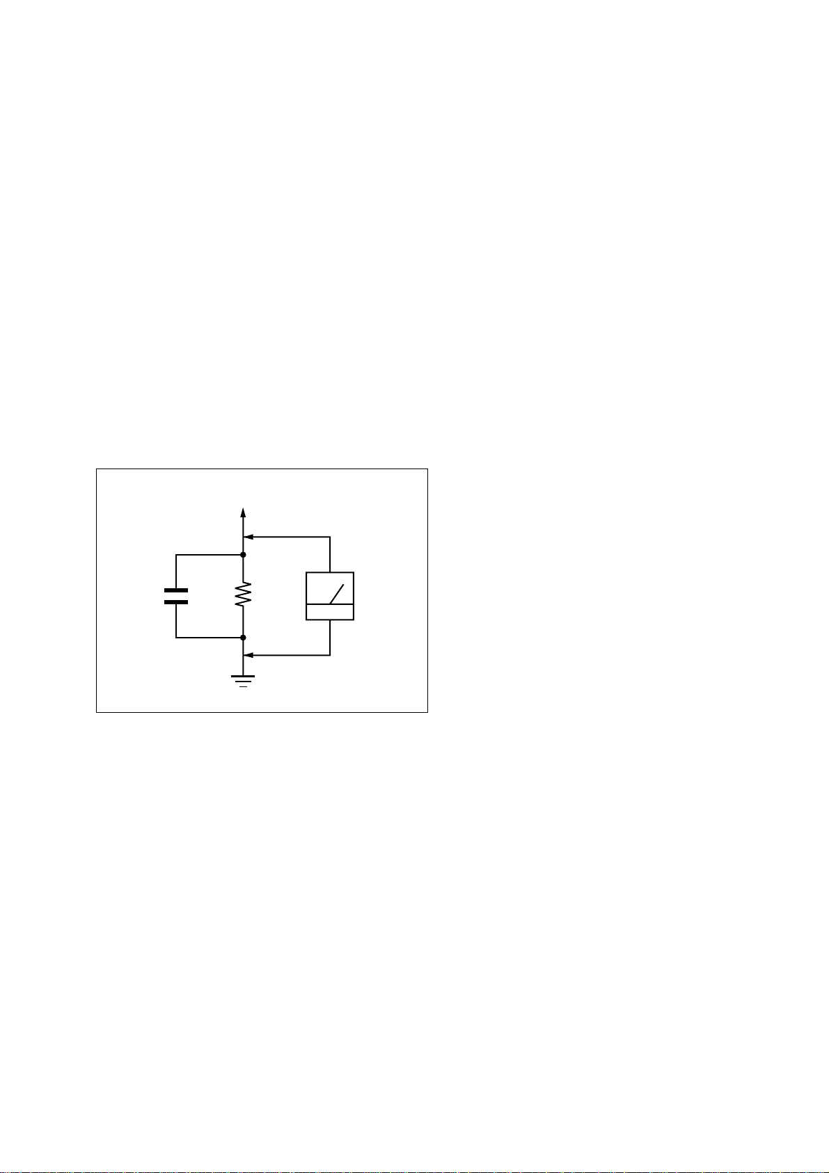
3. Measuring the voltage drop across a resistor by means of a
VOM or battery-operated AC voltmeter . The “limit” indication
is 0.75 V, so analog meters must have an accurate low-voltage
scale. The Simpson 250 and Sanwa SH-63Trd are examples
of a passive VOM that is suitable. Nearly all battery operated
digital multimeters that have a 2 V A C range are suitable. (See
Fig. A)
To Exposed Metal
Parts on Set
Notes on chip component replacement
• Never reuse a disconnected chip component.
• Notice that the minus side of a tantalum capacitor may be
damaged by heat.
AC
0.15 µF
1.5 k
Ω
Earth Ground
voltmete
(0.75 V)
Fig. A. Using an AC voltmeter to check AC leakage.
SAFETY-RELATED COMPONENT WARNING!!
COMPONENTS IDENTIFIED BY MARK 0 OR DOTTED LINE
WITH MARK 0 ON THE SCHEMATIC DIAGRAMS AND IN
THE PARTS LIST ARE CRITICAL TO SAFE OPERATION.
REPLACE THESE COMPONENTS WITH SONY PARTS WHOSE
PART NUMBERS APPEAR AS SHOWN IN THIS MANUAL OR
IN SUPPLEMENTS PUBLISHED BY SONY.
ATTENTION AU COMPOSANT AYANT RAPPORT
LES COMPOSANTS IDENTIFIÉS P AR UNE MARQ UE 0 SUR
LES DIAGRAMMES SCHÉMATIQUES ET LA LISTE DES
PIÈCES SONT CRITIQUES POUR LA SÉCURITÉ DE
FONCTIONNEMENT. NE REMPLACER CES COM- POSANTS
QUE PAR DES PIÈCES SONY DONT LES NUMÉROS SONT
DONNÉS DANS CE MANUEL OU D ANS LES SUPPLÉMENTS
PUBLIÉS PAR SONY.
À LA SÉCURITÉ!
3
Page 4

STR-DA5200ES
TABLE OF CONTENTS
1. SERVICING NOTES .............................................. 5
2. GENERAL .................................................................. 11
3. DISASSEMBLY
3-1. Disassembly Flow .......................................................... 19
3-2. Case ................................................................................ 20
3-3. Front Panel Assy............................................................. 20
3-4. S-VIDEO/CIS Board...................................................... 21
3-5. Tuner............................................................................... 21
3-6. E-VOLUME Board ........................................................ 22
3-7. VIDEO Board................................................................. 22
3-8. ZONE3/SP TERMIN AL Board...................................... 23
3-9. AUDIO Board................................................................. 23
3-10. DC-DC-HDMI Board/Power Transformer (T01) ........... 24
3-11. MAIN Board................................................................... 24
4. TEST MODE............................................................. 25
5. ELECTRICAL ADJUSTMENTS ........................ 28
6. DIAGRAMS
6-1. Block Diagram – CONTROL Section – ......................... 29
6-2. Block Diagram – DSP Section – .................................... 30
6-3. Block Diagram
– HDMI RECEIVER/TRANSCEIVER Section – ......... 31
6-4. Block Diagram – VIDEO PROCESS Section – ............. 32
6-5. Block Diagram – USB, XM RECEIVER Section –....... 33
6-6. Block Diagram – ANALOG AUDIO Section – ............. 34
6-7. Block Diagram – POWER AMP Section – .................... 35
6-8. Block Diagram – VIDEO Section – ............................... 36
6-9. Block Diagram – DISPLAY Section – ........................... 37
6-10. Block Diagram – POWER SUPPLY Section – .............. 38
6-11. Printed Wiring Board
– DIGITAL Board (Component Side) – ......................... 40
6-12. Printed Wiring Board
– DIGITAL Board (Conductor Side) – ........................... 41
6-13. Schematic Diagram – DIGITAL Board (1/5) – .............. 42
6-14. Schematic Diagram – DIGITAL Board (2/5) – .............. 43
6-15. Schematic Diagram – DIGITAL Board (3/5) – .............. 44
6-16. Schematic Diagram – DIGITAL Board (4/5) – .............. 45
6-17. Schematic Diagram – DIGITAL Board (5/5) – .............. 46
6-18. Schematic Diagram – HDMI Board (1/9) – ................... 47
6-19. Schematic Diagram – HDMI Board (2/9) – ................... 48
6-20. Schematic Diagram – HDMI Board (3/9) – ................... 49
6-21. Schematic Diagram – HDMI Board (4/9) – ................... 50
6-22. Schematic Diagram – HDMI Board (5/9) – ................... 51
6-23. Schematic Diagram – HDMI Board (6/9) – ................... 52
6-24. Schematic Diagram
– HDMI Board (7/9) (US and Canadian models) –........ 53
6-25. Schematic Diagram – HDMI Board (8/9) – ................... 54
6-26. Schematic Diagram – HDMI Board (9/9) – ................... 55
6-27. Printed Wiring Board – HDMI Board (Side A) –........... 56
6-28. Printed Wiring Board – HDMI Board (Side B) – ........... 57
6-29. Printed Wiring Board – DSP Board – ............................ 58
6-30. Schematic Diagram – DSP Board – ............................... 59
6-31. Printed Wiring Board – USB Board – ............................ 60
6-32. Schematic Diagram – USB Board (1/3) – ...................... 61
6-33. Schematic Diagram – USB Board (2/3) – ...................... 62
6-34. Schematic Diagram – USB Board (3/3) – ...................... 63
6-35. Printed Wiring Board – CIS Board –.............................. 64
6-36. Schematic Diagram – CIS Board – ................................ 65
6-37. Printed Wiring Board
– AUDIO Board (Component Side) – ............................ 66
6-38. Printed Wiring Board
– AUDIO Board (Conductor Side) – .............................. 67
6-39. Schematic Diagram – AUDIO Board (1/2) – ................. 68
6-40. Schematic Diagram – AUDIO Board (2/2) – ................. 69
6-41. Printed Wiring Boards – E-VOLUME Section – ........... 70
6-42. Schematic Diagram – E-VOLUME Section –................. 71
6-43. Printed Wiring Board – A CLASS AMP Board – .......... 72
6-44. Schematic Diagram – A CLASS AMP Board – ............. 73
6-45. Printed Wiring Board – POWER AMP Board – ............ 74
6-46. Schematic Diagram – POWER AMP Board – ............... 75
6-47. Printed Wiring Board – BIAS Board – ........................... 76
6-48. Schematic Diagram – BIAS Board – ............................. 77
6-49. Schematic Diagram – MAIN Board (1/2) – ................... 78
6-50. Schematic Diagram – MAIN Board (2/2) – ................... 79
6-51. Printed Wiring Board – MAIN Board – ......................... 80
6-52. Printed Wiring Board – VIDEO Board –........................ 81
6-53. Schematic Diagram – VIDEO Board (1/2) –.................. 82
6-54. Schematic Diagram – VIDEO Board (2/2) –.................. 83
6-55. Printed Wiring Board – S-VIDEO Board – .................... 84
6-56. Schematic Diagram – S-VIDEO Board –....................... 85
6-57. Printed Wiring Boards
– SP TERMINAL/VIDEO 3 Boards – ........................... 86
6-58. Schematic Diagram
– SP TERMINAL/VIDEO 3 Boards – ........................... 87
6-59. Printed Wiring Board – DISPLAY Board – ................... 88
6-60. Schematic Diagram – DISPLAY Board – ...................... 89
6-61. Printed Wiring Boards – KEY Section – ........................ 90
6-62. Schematic Diagram – KEY Section – ............................ 91
6-63. Printed Wiring Boards – DC Section – .......................... 92
6-64. Printed Wiring Boards – AC Section –........................... 93
6-65. Schematic Diagram – POWER SUPPLY Section – ....... 94
7. EXPLODED VIEWS
7-1. Case Section ................................................................... 147
7-2. DISPLAY Board Block .................................................. 148
7-3. Front Panel Block...........................................................149
7-4. VIDEO Board Block ...................................................... 150
7-5. AUDIO Board Block ...................................................... 151
7-6. MAIN Board Block ........................................................ 152
7-7. Heat Sink Block.............................................................. 153
8. ELECTRICAL PARTS LIST...............................154
4
Page 5
SECTION 1
SERVICING NOTES
STR-DA5200ES
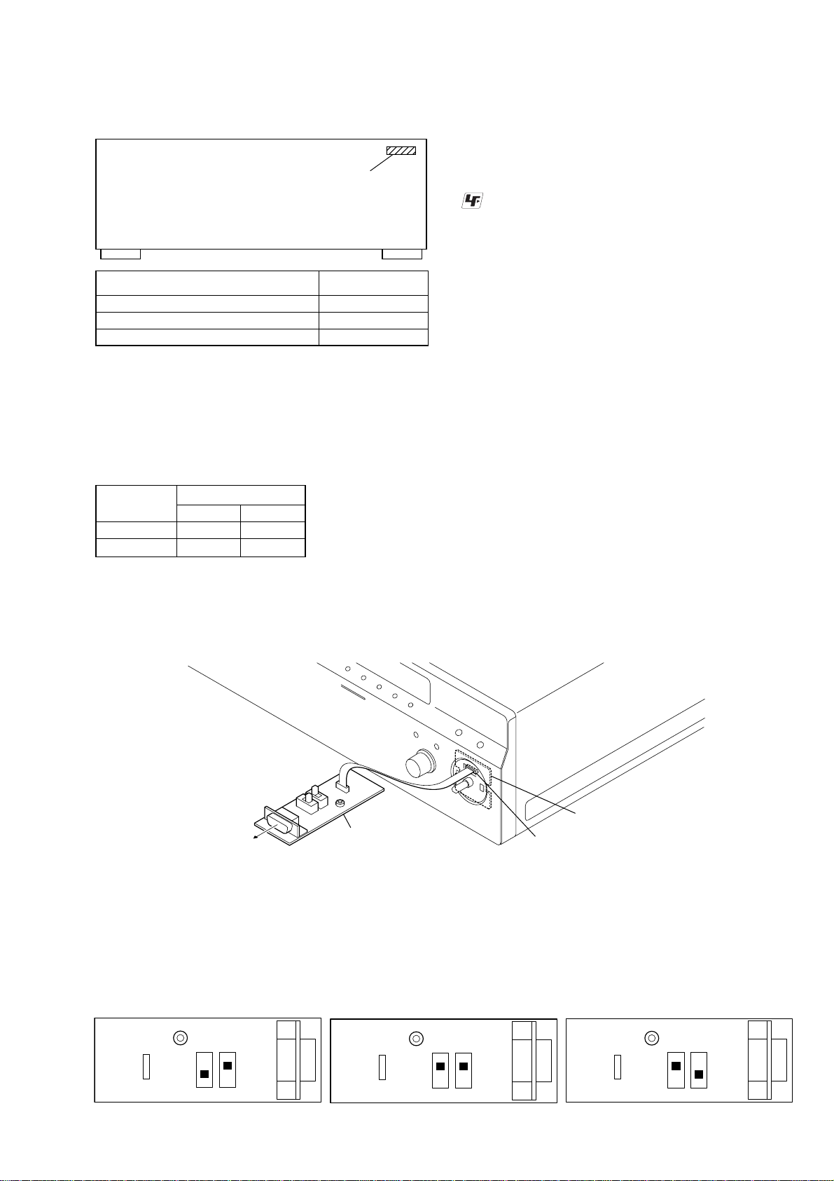
• MODEL IDENTIFICATION
– Back Panel –
PART No.
Model PART No.
US and Canadian models 2-668-097-7[]
AEP model 2-668-097-8[]
UK model 2-668-097-9[]
NOTE OF REPLACING THE IC3509 AND IC3513 ON
THE HDMI BOARD
When IC3509 and IC3513 on the HDMI board are damaged,
exchange the new HDMI board for the HDMI board which IC
damaged. When throwing away the HDMI board, be sure to throw
away after destroying IC3509 and IC3513 physically with the
hammer etc.
COLOR VARIATION
Destination
US, Canadian z
AEP, UK zz
COLOR
BLACK SILVER
UNLEADED SOLDER
Boards requiring use of unleaded solder are printed with the leadfree mark (LF) indicating the solder contains no lead.
(Caution: Some printed circuit boards may not come printed with
the lead free mark due to their particular size)
: LEAD FREE MARK
Unleaded solder has the following characteristics.
• Unleaded solder melts at a temperature about 40 °C higher
than ordinary solder.
Ordinary soldering irons can be used but the iron tip has to be
applied to the solder joint for a slightly longer time.
Soldering irons using a temperature regulator should be set to
about 350 °C.
Caution: The printed pattern (copper foil) may peel away if
the heated tip is applied for too long, so be careful!
• Strong viscosity
Unleaded solder is more viscou-s (sticky, less prone to flow)
than ordinary solder so use caution not to let solder bridges
occur such as on IC pins, etc.
• Usable with ordinary solder
It is best to use only unleaded solder but unleaded solder may
also be added to ordinary solder.
NOTE THE IC3601 ON THE HDMI BOARD AND
IC084 ON THE USB BOARD REPLACING
Replacement of IC3601 on the HDMI board and IC084 on the USB
board used in this set requires a special tool.
UPDATE OF SOFTWARE OF THE SYSTEM CONTROLLER (IC2054)/HDMI CONTROLLER (IC3610)/
USB CONTROLLER (IC006)
Perform operation of the following when the update of software of the system controller (IC2054)/HDMI controller (IC3610)/USB controller
(IC006) is necessary.
Connect:
M-VOLA3 board
CN713
for PC
JIG
(Part No. : J-2501-300-A)
Procedure:
1. Turn off the main power and setting the jig referring to Fig. 1 (Note: Do this setting before connecting jig with the set).
2. Remove the KNOB (VOL) ASSY and connect CN713 (M-VOLA3 board) and PC by using the jig.
3. Turn on the main power and perform the operation according to the application.
4. After “Please Reset” is displayed, reset switch on the jig is pushed and update is completed.
5. Turn off the main power and remove the jig.
6. Turn on the main power.
When system controller (IC2054) is updated
(RESET)
SW2
SW1
SW1: up, SW2: down
Fig.1 Setting for jig
When HDMI controller (IC3610) is updated
(RESET)
SW2
SW1: up, SW2: up
SW1
When USB controller (IC006) is updated
(RESET)
SW2
SW1
SW1: down, SW2: up
5
Page 6
STR-DA5200ES
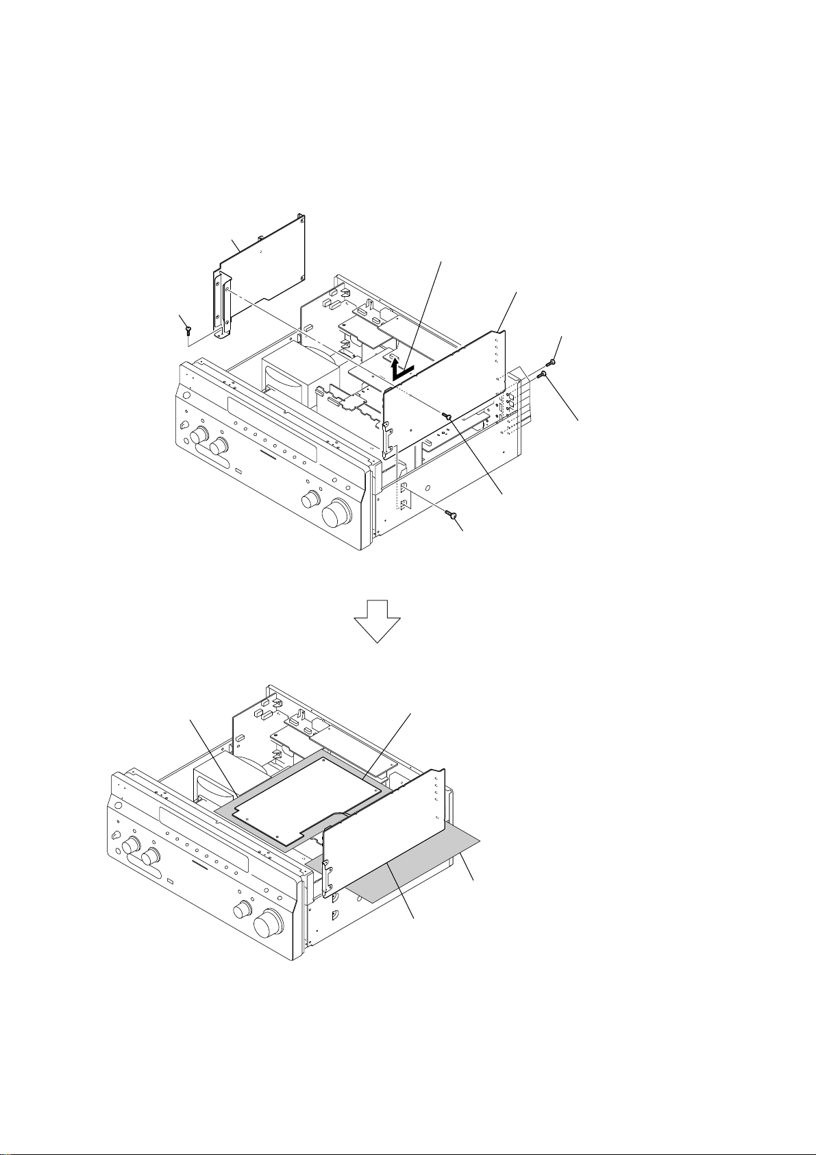
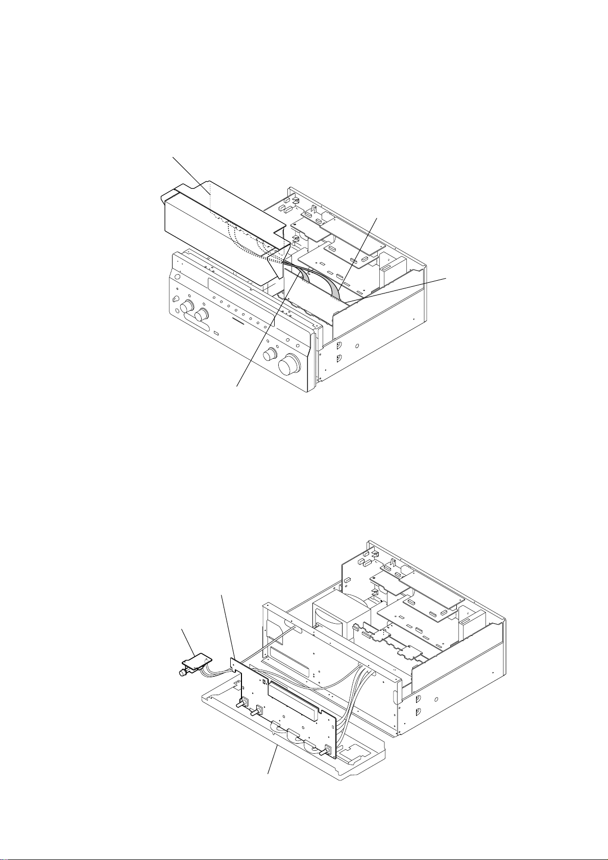
t
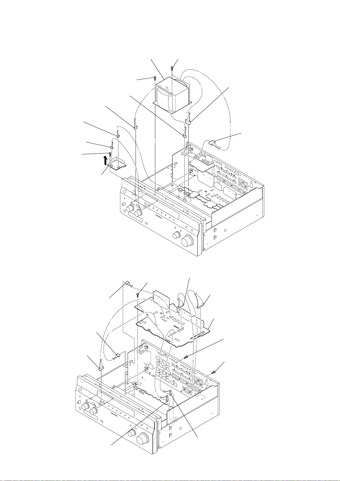
DIGITAL/HDMI BOARDS SERVICE POSITION
Note: Follow the disassembly procedure in the numerical order given.
7
HDMI board
1
screw
×
(BVTP3
8)
5
Raise and remove upwards after pulling to the front.
8
DIGITAL board
3
four screws
(B3
×
6)
insulated sheet
HDMI board
4
two screws
(BVTP3
6
screw
(BVTP3
×
8)
2
×
8)
nine screws
(BVTP3
×
8)
insulated shee
DIGITAL board
Note: In checking the DIGITAL board, remove the HDMI board.
6
Page 7
STR-DA5200ES
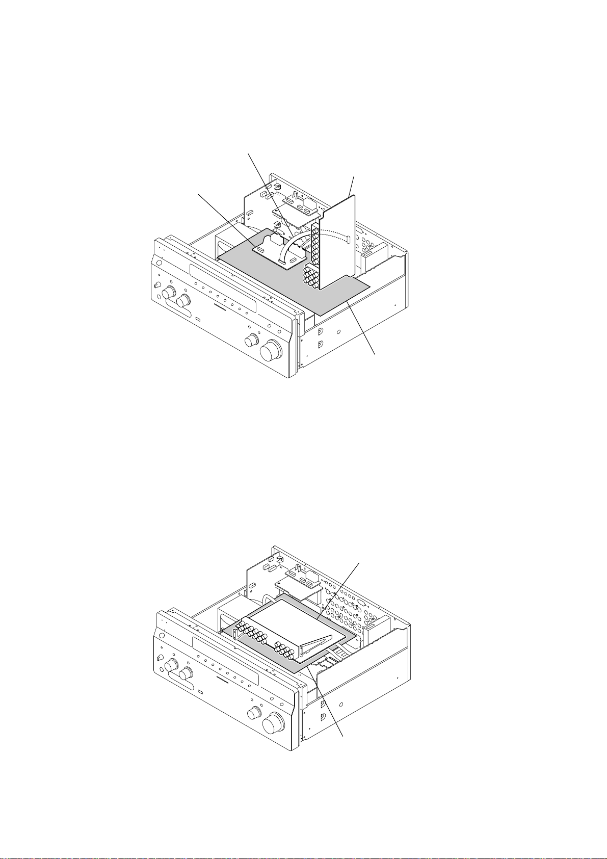
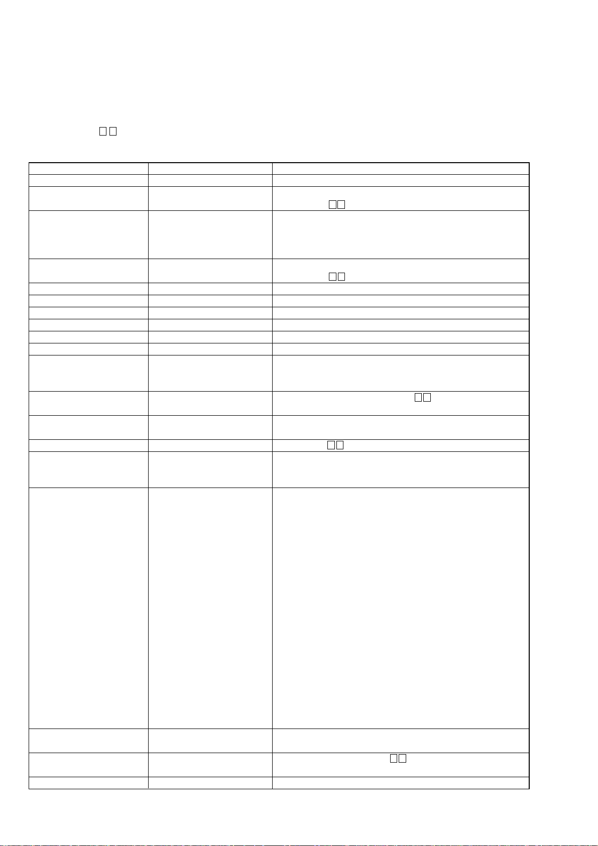
AMP BLOCK SERVICE POSITON
In checking the AMP block, prepare jig (extension cable J-2501-290-A: 500 mm 9 core/J-2501-291-A: 500 mm 12 core).
A CLASS AMP board
Connect jig (extension cable
J-2501-291-A) to the E-VOLUME board
(CNS1201) and A CLASS AMP board
(CNS1501).
E-VOLUME board
Connect jig (extension cable J-2501-290-A)
to the E-VOLUME board (CNS1202) and A CLASS AMP board (CNS1502).
DISPLAY BOARD SERVICE POSITON
DISPLAY board
POWER SW board
front panel block
7
Page 8
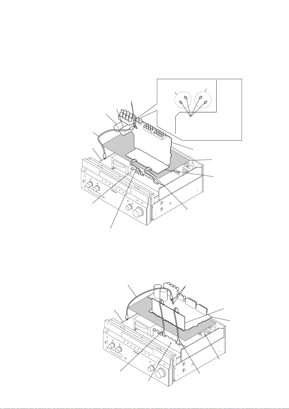
STR-DA5200ES
t
VIDEO BOARD SERVICE POSITON
In checking the VIDEO board, prepare jig (extension cable J-2501-231-A: 300 mm 15 core).
Connect jig (extension cable J-2501-231-A)
to the VIDEO board (CN6802) and S-VIDEO board (CNS6903).
VIDEO board
S-VIDEO board
AUDIO BOARD SERVICE POSITON
In checking the AUDIO board, remove the VIDEO board and S-VIDEO board.
insulated shee
AUDIO board
insulated sheet
8
Page 9
STR-DA5200ES
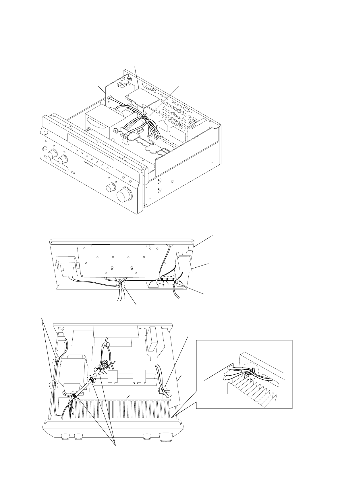
MAIN/E-VOLUME BOARDS SERVICE POSITON
In checking the MAIN/E-VOLUME board, prepare jig (extension cable J-2501-290-A: 500 mm 9 core/J-2501-291-A: 500 mm 12 core).
Note: Be sure to ground the MAIN board with a clip when checking it.
– MAIN board –
JWH1210, JWH1208
(Even if it attaches a clip in JWH1208
and attaches it in JWH1210, it is satisfactory.)
C1402
C1401
clip
chassis
A CLASS AMP board
CAUTION
C1402
C1401
In checking the board, make two
capacitors discharge for electric
shock prevention. (R: 800
MAIN board
Extension cable (Part No. : J-2501-291-A)
to the E-VOLUME board (CNS1201) and
A CLASS AMP board (CNS1501).
Ω
/2W)
insulated sheet
E-VOLUME board
– E-VOLUME board –
Extension cable (Part No. : J-2501-290-A)
to the E-VOLUME board (CNS1202) and
A CLASS AMP board (CNS1502).
clip
chassis
JWH1210, JWH1208
(Even if it attaches a clip in JWH1208
and attaches it in JWH1210,
it is satisfactory.)
E-VOLUME board
MAIN board
insulated sheet
Extension cable (Part No. : J-2501-290-A)
to the E-VOLUME board (CNS1202) and
A CLASS AMP board (CNS1502).
A CLASS AMP board
Extension cable (Part No. : J-2501-291-A)
to the E-VOLUME board (CNS1201) and
A CLASS AMP board (CNS1501).
9
Page 10
STR-DA5200ES
HARNESS SETTING
AC board
SP TERMNAL board
Please band together so that the ribbon cable (5pin) to AC board
and the ribbon cable (4 pin) from SP TERMNAL board
do not approach the primary side parts of AC board.
Please band together so that a primary side
cable cannot touch a power transformer.
power
transformer
front panel block
POWER SW board
Please band together so that a ribbon cable
does not approach a primary side
of POWER SW board.
Please band the cable from a VIDEO 3 board
together in this position.
Please band together so that the ribbon cable
from a DIGITAL board cannot touch a heat sink.
Please band together by purse lock
so that a cable cannot touch a heat sink.
DIGITAL
board
heat sink
heat sink
10
Please band together so that a cable cannot touch
a power transformer and a heat sink.
Page 11
SECTION 2
GENERAL
This section is extracted from
instruction manual.
Getting Started
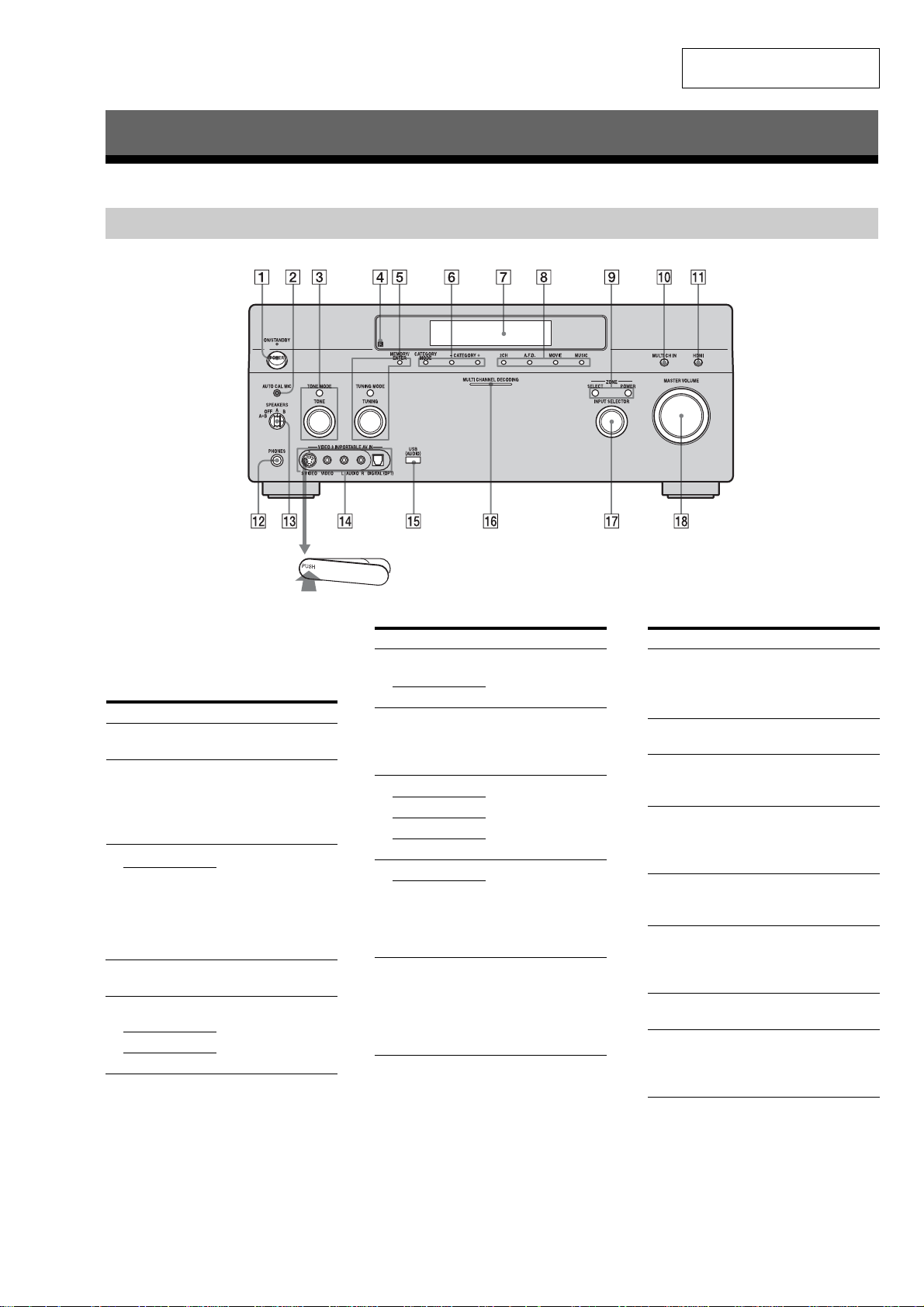
Description and location of parts (US and Canadian models)
Front panel
STR-DA5200ES
To remove the cover
Press PUSH.
When you remove the cover, keep it out of
reach from children.
Name Function
A POWER Press to turn the
B AUTO CAL MIC
jack
C TONE MODE Adjusts FRONT B ASS
TONE
D Remote sensor Receives signals from
E MEMORY/
ENTER
TUNING MODE
TUNING
receiver on or off
Connects to the
supplied optimizer
microphone for the
Digital Cinema Auto
Calibration function.
and FRONT TREBLE.
Press TONE MODE
repeatedly to select
BASS or TREBLE,
then turn TONE to
adjust the level.
remote commander.
Press to operate a tuner
(FM/AM/XM Radio).
Name Function
F CATEGORY
MODE
CA TEGOR Y +/–
G Display
window
H 2CH Press to select sound
A.F.D.
MOVIE
MUSIC
I POWER Press SELECT
SELECT
J MULTI CH IN Press to select the audio
Used when listening to
XM Radio.
The current status of
the selected component
or a list of selectable
items appears here.
field.
repeatedly to select
zone 2 or zone 3, then
press POWER to
output signals to the
selected zone.
input signal from the
component connected
to the MULTI
CHANNEL INPUT
jack.
Name Function
K HDMI Press to select input
L PHONES jack Connects to
M SPEAKERS
(OFF/A/B/A+B)
N VIDEO 3 IN/
PORT ABLE AV
IN jacks
O USB (AUDIO)
jack
P MULTI
CHANNEL
DECODING
lamp
Q INPUT
SELECTOR
R MASTER
VOLUME
source from the
component connected
to the HDMI IN jack.
headphones.
Switch to OFF, A, B,
A+B of the front
speakers.
Connect to a portable
audio/video component
such as a camcorder or
video game.
Connects to a portable
audio product with a
USB jack.
Lights up when multichannel audio signals
are decoded.
Turn to select the input
source to play back.
Turn to adjust the
volume level of all
speakers at the same
time.
11
Page 12

STR-DA5200ES
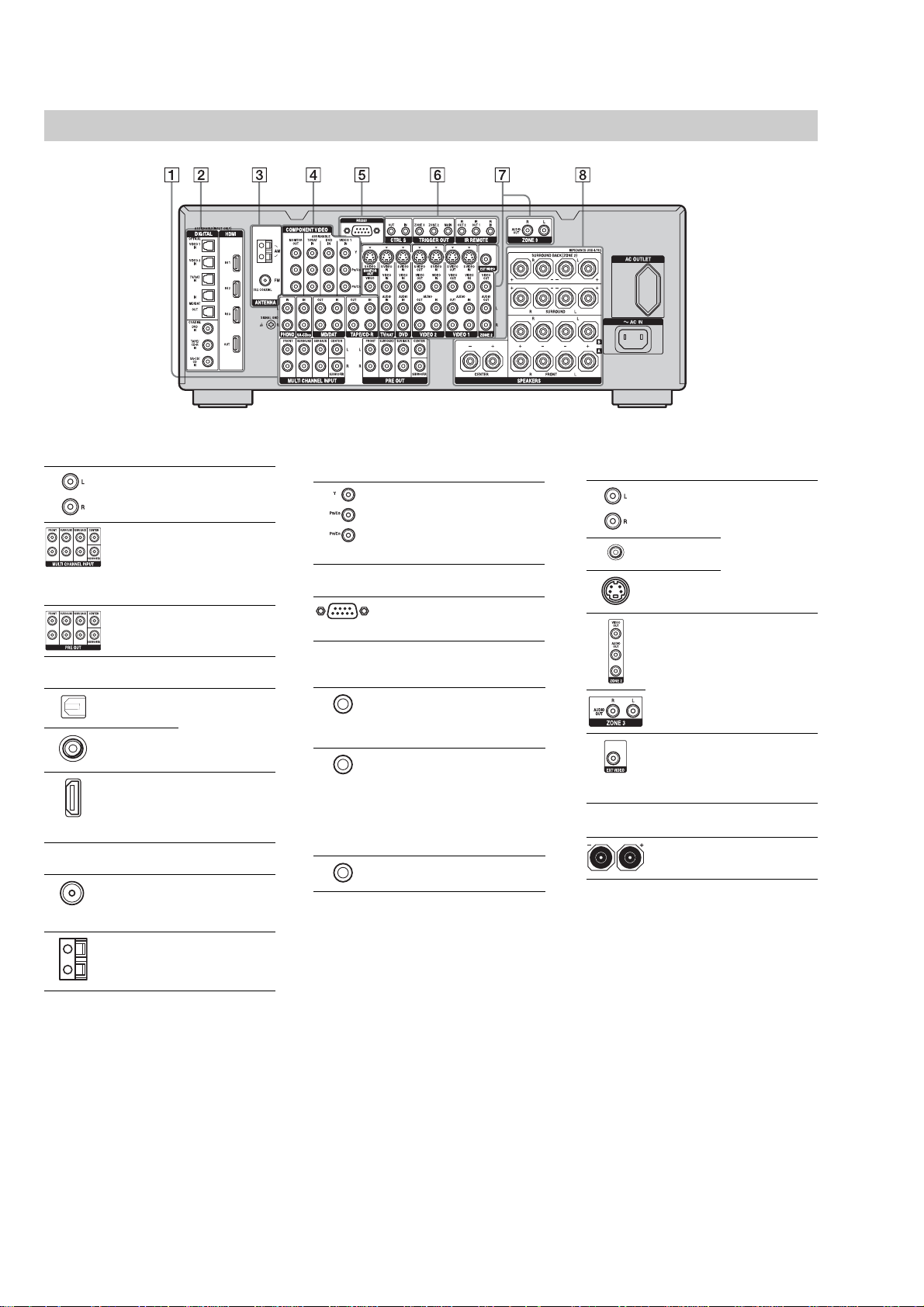
Rear panel
A AUDIO INPUT/OUTPUT section
AUDIO IN/
OUT jacks
MULTI
CHANNEL
INPUT jacks
PRE OUT jacks Connect to an
Connect to a tape
deck, MD deck or
DAT player, etc.
Connect to a Super
Audio CD player or
DVD player with an
analog audio jack for
7.1 channel or 5.1
channel sound.
external power
amplifier.
B DIGITAL INPUT/OUTPUT section
OPTICAL IN/
OUT jacks
COAXIAL IN
jacks
HDMI IN/OUT
jacks
Connects to a DVD
player, Super Audio
CD player, etc. The
COAXIAL jack
provides a better
quality sound.
Connects to a DVD
player, or a satellite
tuner. An image and
the sound are output
to TV or a projector.
C ANTENNA section
FM ANTENNA
jack
AM
ANTENNA
jack
XM
ANTENNA
jack
Connects to the FM
wire antenna (aerial)
supplied with this
receiver.
Connects to the AM
loop antenna (aerial)
supplied with this
receiver.
Connects to the XM
Connect-and-Play
antenna (aerial) (not
supplied).
D COMPONENT VIDEO INPUT/
OUTPUT section
COMPONENT
VIDEO (Y, P
, PR/CR)
C
B
INPUT/
OUTPUT
jacks*
Connect to a DVD
player, TV, or a
/
B
satellite tuner.
E RS-232C jack
Used for
maintenance and
service.
F Control jack for Sony equipment
and other external components
CTRL S IN/
OUT jacks
TRIGGER
OUT jacks
IR REMOTE
IN/OUT jacks
Connects to Sony
TV, DVD player or
VCR with
CONTROL S jack.
Connects to in terlock
on/off of the power
supply of other 12V
TRIGGER
compliant
components, or the
amplifier/receiver of
zone 2 or zone 3.
Connects an IR
repeater.
G VIDEO/AUDIO INPUT/OUTPUT
section
AUDIO IN/
OUT jacks
VIDEO IN/
OUT jacks*
S VIDEO IN/
OUT jacks*
AUDIO IN/
OUT jack
VIDEO IN/
OUT jacks
VIDEO IN jack Connects to the
Connects to a VCR
or a DVD player etc.
Connects to the
component in zone 2
or zone 3.
component when
you want to watch in
PIP (Picture in
Picture) window.
H SPEAKERS section
Connects to speakers.
*You can watch the selected input image when you
connect the MONITOR OUT jack to a TV.
You can operate this receiver using a GUI
(Graphical User Interface).
12
Page 13
STR-DA5200ES
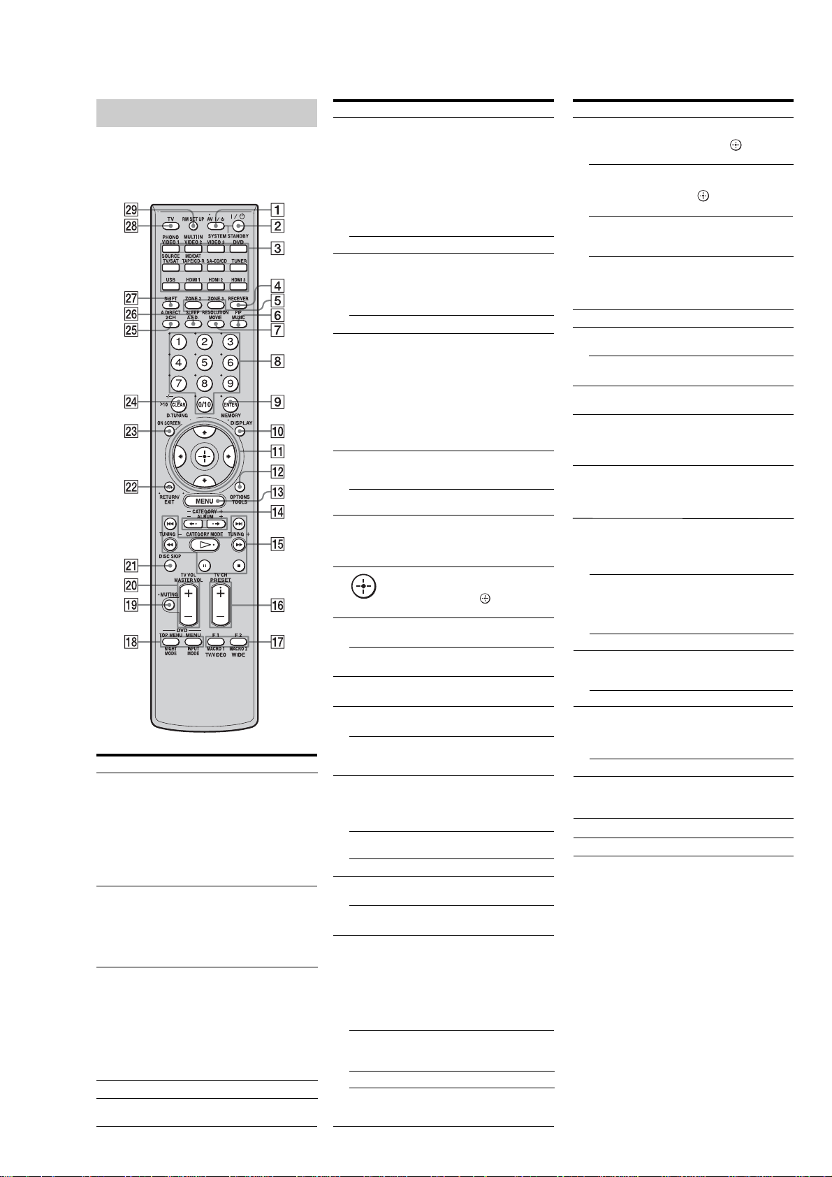
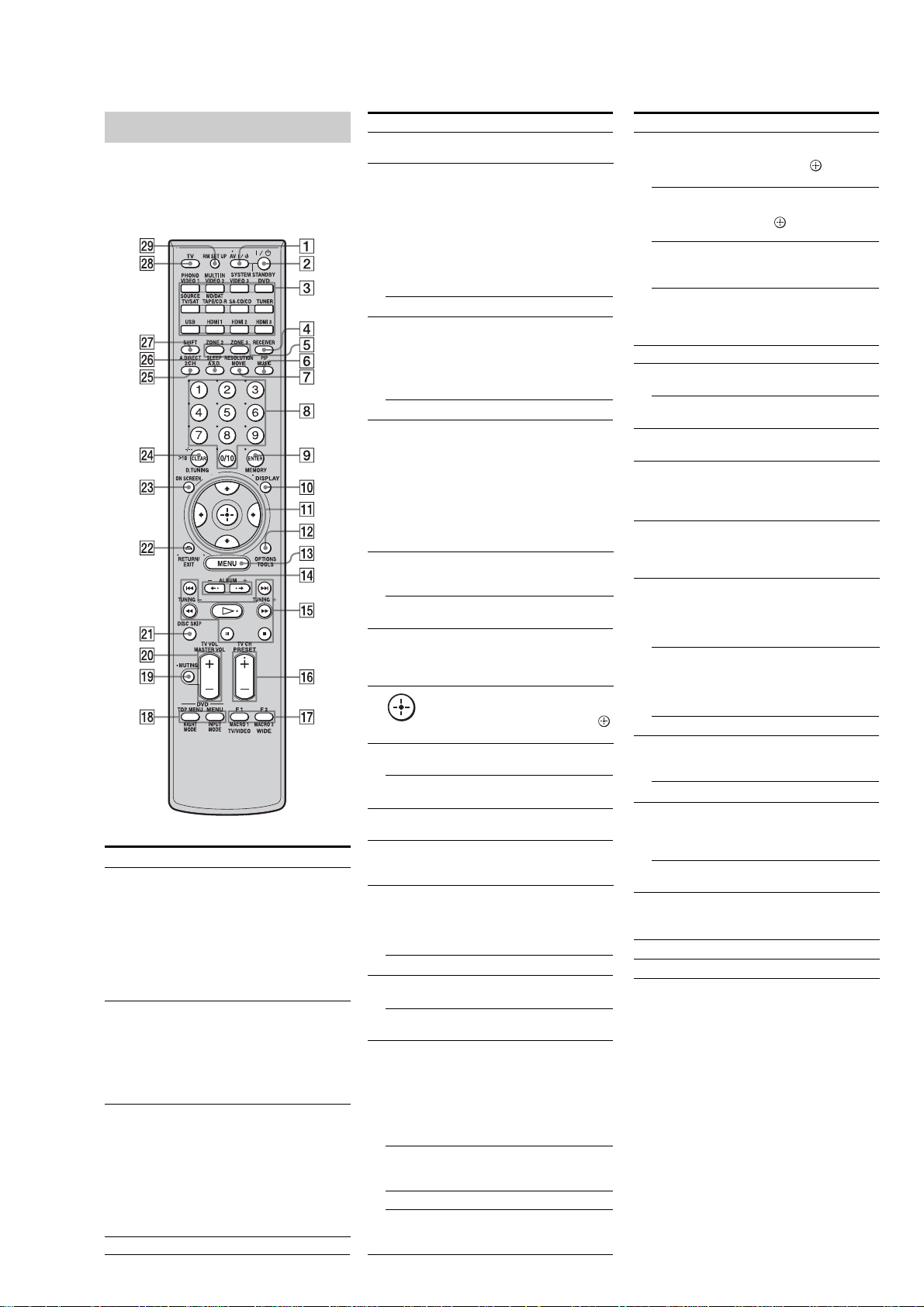
Remote commander
You can use the supplied remote RM-AAL005 tooperate
the receiver and to control the Sony audio/video
components that the remote is assigned to operate.
RM-AAL005
Name Function
A AV ?/1 (on/
standby)
B ?/1 (on/
standby)
C Input
buttons
D RECEIVER
E ZONE 2
ZONE 3
Press to turn on or off the audio/video
components that the remote is assigned to
operate.
If you press the ?/1 (B) at the same time,
it will turn off the receiver and other Sony
components (SYSTEM STANDBY).
Note
The function of the AV ?/1 switchchanges
automatically each time youpress the input
button (C).
Press to turn the receiver on or off.
If ZONE 2 or ZONE 3 is selected, only the
main receiver is turned on oroff with this
button. To turn off all components
including an amplifier in zone 2 or zone 3,
press ?/1 and AV ?/1 (A) at the same
same time (SYSTEM STANDBY).
Press one of the buttons to select the
component you want to use.
Press a pink-labeled button after pressing
SHIFT (wj). When you press any of the
input buttons, the receiver turns on.
The buttons are factory assigned to control
Sony components. You can program the
remote to to control non-Sony components
following the steps in “Programming the
remote”.
Press to enable the receiver operation.
Press to enable the zone 2/zone 3
operation.
Name Function
F PIP Press SHIFT (wj), then press PIP toswitch
MUSIC Press to select sound field.
RESOLUTION
G
MOVIE Press to select sound field.
H Numeric
buttons
ENTER
I
MEMORY Press to store a station during tuner
J DISPLAY Press to select information displayed on the
K
V/v/B/b
L OPTIONS Press to display and select items from option
TOOLS Press to display and select items from option
M MENU Press to display the menu of the
N CATEGORY
+/–
ALBUM +/– Press to replay the previous scene or fast
O m /M
x
X
b)
H
./>
CATEGORY
MODE
TUNING +/– Press to selest station.
P PRESET
b)
/–
+
TV CH +/ – Press TV (wk) and then press TV CH+/−
Q F1/F2 Press TV (wk) and then press F1 or F2 to
TV/VIDEO Press TV/VIDEO and TV (wk) atthe same
WIDE Press to select the wide picture mode.
MACRO1,
MACRO2
the image of the PIP (Picture in Picture)
window.
The image will be changed as follows.
EXT VIDEO t ZONE 2 VIDEO t
OFF. You canalso change the size of the
PIP window by pressing V/v.
Note
The HDMI video signals are not output
while the PIP window is displayed.
Press SHIFT (wj) then press
RESOLUTION repeatedly to change the
resolution of signals output from the
HDMI OUT or COMPONENT
VIDEO MONITOR OUT jack.
Press to
− preset/tune to preset stations.
− select track numbers of the CD player,
DVD player or MD deck. Press 0/10 to
select track number 10.
− select channel numbers of the VCR or
satellite tuner.
− After pressing TV (wk), press the
numeric buttons to select the TV
channels.
Press to enter the value after selecting a
channel, disc or track using the numeric
buttons.
operation.
display window, TV screen of the VCR,
satellite tuner, CD player, DVD player, or
MD deck.
After pressing MENU (qd) or TOP MENU
(qk), press V/v, B or b to select the
settings. Then press
selection.
menus for receiver and DVD player.
menus for DVD player, etc.
receiver of a DVD player, TV, etc.
Press to select the category for XM Radio.
forward the current scene of the VCR or
DVD player.
Press to operate the DVD player, CD
player, MD deck or tape deck, etc.
Press to select the category mode for XM
Radio.
Press to register FM/AM/XM Radio
stations or to select preset stations.
to operate the TV, satellite tuner, VCR, etc.
select a component to operate.
• HDD recorder
F1: HDD
F2: DVD
• DVD/VHS combo player
F1: DVD
F2: VHS
time to select the input signal (TV input or
video input).
Press RECEIVER (4) and then press
MACRO 1 or MACRO 2 to set up the
macro function.
to enter the
Name Function
R TOP MENU Press to display the menu or on-screen
MENU Press to display the menus of the DVD
NIGHT
MODE
INPUT
MODE
S MUTING Press to silence the sound.
T MASTER
VOL +
TV VOL +/– Press TV (wk) and then press TV VOL +/−
U DISC SKIP Press to skip a disc when using a multi-disc
V RETURN/
EXIT O
W ON SCREEN Press to turn the GUI display mode on or
X CLEAR Press to
>10 Press to select
D.TUNING Press to enter direct tuning mode.
Y A.DIRE CT Press SHIFT (wj) then press A.DIRECT
2CH Press to select sound filed.
Z SLEEP Press SHIFT (wj) then press SLEEP to
A.F.D Press to select sound filed.
wj SHIFT Press to light up the button. It changes the
wk TV Press to enable the TV operation.
wl RM SET UP Press to set up the remote.
b)
The tactile dot is attached to these buttons (H, PRESET+).
Use as a mark of operation.
guide of the DVD player on the TV screen.
Then use V/v/B/b and
menu operations.
player on the TV screen. Then use
V/v/B/b and
operations.
Press RECEIVER (4) and then press
NIGHT MODE to activate the NIGHT
MODE function.
Press RECEIVER (4) and then press
INPUT MODE to select the input mode
when the same components are connected
to both digital and analog jacks.
Press to adjust the volume level of all
b)
/–
speakers at the same time.
to adjust the volume level of the TV.
changer.
Press to return to the previous menu or exit
the menu while the menu or on-screen guide
of the VCR, DVD player, or satellite tuner
is displayed on the TV screen.
off. Press MENU (qd) to display the menu
when “GUI ON” appears on the display.
− clear a mistake when you press the
incorrect numeric button.
− return to continuous playback, etc. of
the satellite tuner or DVD player.
− track numbers over 10 of the VCR,
satellite tuner, CD player or MD deck.
− channel numbers of the Digital CATV
terminal.
to switch the audio of the selected input to
analog signal without any adjustment.
activate the Sleep Timer function and the
duration which the receiver turns off
automatically.
remote button function to activate the
buttons with pink printing.
to perform
to perform a menu
Notes
• Some functions explained in this section may not work
depending on the model.
• The above explanation is intended to serve as an example only.
Therefore, depending on the component, the above operation
may not be possible or may operate differently than described.
13
Page 14
STR-DA5200ES
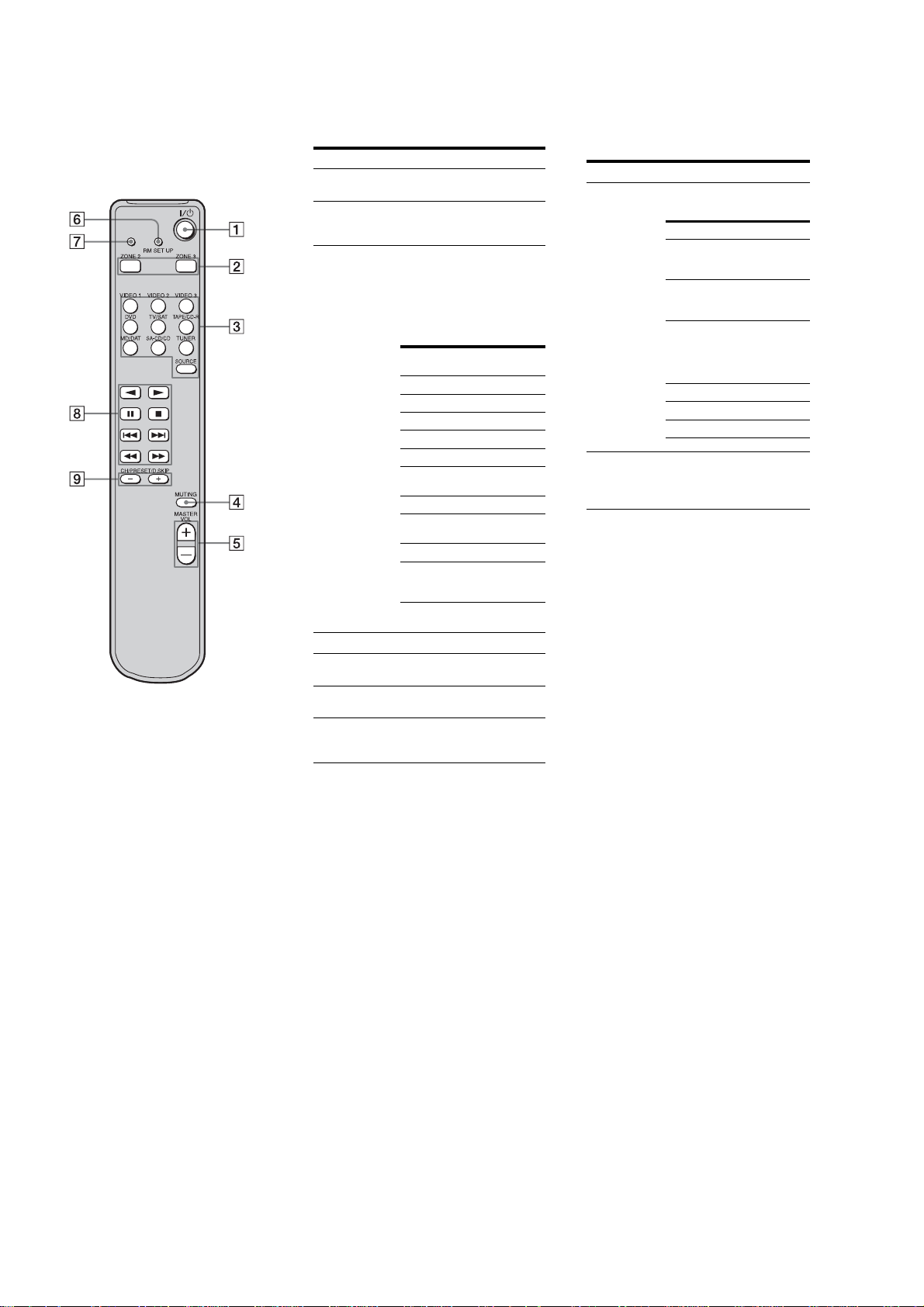
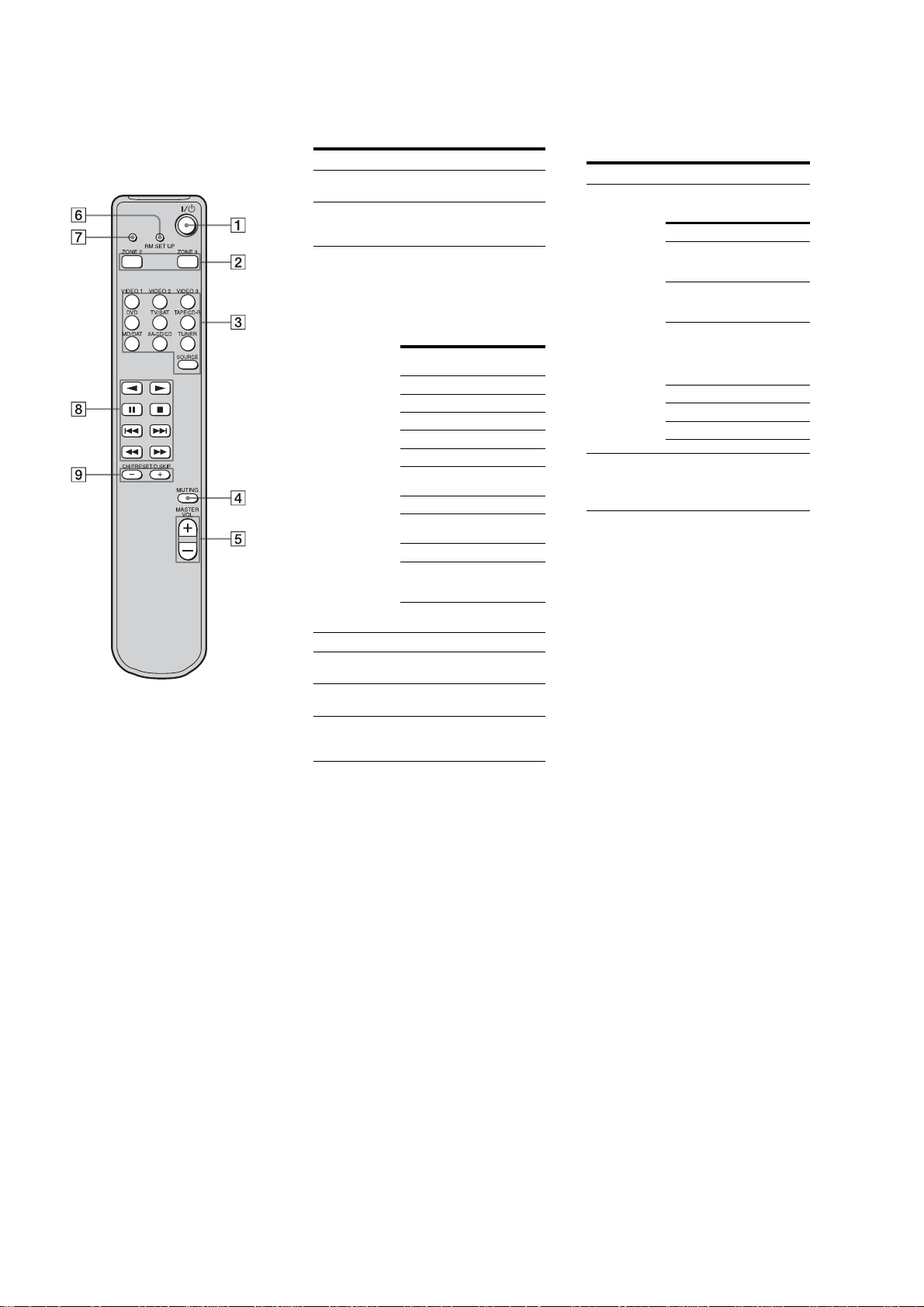
RM-AAU009
This remote is onl y for zone 2/zone 3
operations. You cannot control the main
receiver directly with this remote.
Operating the main receiver from
zone 2
Name Function
A ?/1 (on/
standby)
B Command
mode
buttons
C Input
buttons
Press to turn a receiver in zone 2
or zone 3 on or off.
Press to select the command
mode of the remote.
Press one of the buttons to
select the component you want
to use. When you press any of
the input buttons, the receiver
turns on. The buttons are
factory assigned to control Sony
components as f ollows.
Button Assigned Sony
VIDEO 1 VCR (VTR mode 3)
VIDEO 2 VCR (VTR mode 1)
VIDEO 3 VCR (VTR mode 2)
DVDDVD player
TV/SAT TV tuner
TAPE/
CD-R
MD/DAT MD deck
SA-CD/CD Super Audio CD/CD
TUNER* Built-in tuner
SOURCE The cu rre nt input
*The setting cannot be changed.
component
Tape deck B
player
selected for the main
receiver
Operating the components
connected to the main receiver
from zone 2 or zone 3
Name Function
H Operation
buttons*
I CH/
PRESET/
D.SKIP
+/–*
*The function of these buttons switches
automatically each time you pr ess the input
buttons C. The above explanation is intended to
serve as an example only. Therefore, depending
on the component, the above operation may not
be possible or may operate differently than
described.
The following table describes
the function of the buttons.
Button(s) Function
N Starts play . (Starts play
n Starts play on the
X Pauses play or
x Stops play.
./> Skips tracks.
m/M Go backward/forward.
on the front side of the
cassette.)
reverse side of the
cassette.
recording, and starts
recording when the
component is in
recording standby.
Press repeatedly to select a
preset station or channel. When
using a multi-disc changer,
press to skip a disc.
D MUTING Press to mute the sound.
E MASTER
VOL +/–
Press to adjust the volume level
for multi zone output.
F RM SET UP Press to change the cat egory of
the buttons.
G RM SET UP
indicator
Lights up when data is being
sent or when the remote button
assignment is being preset.
14
Page 15
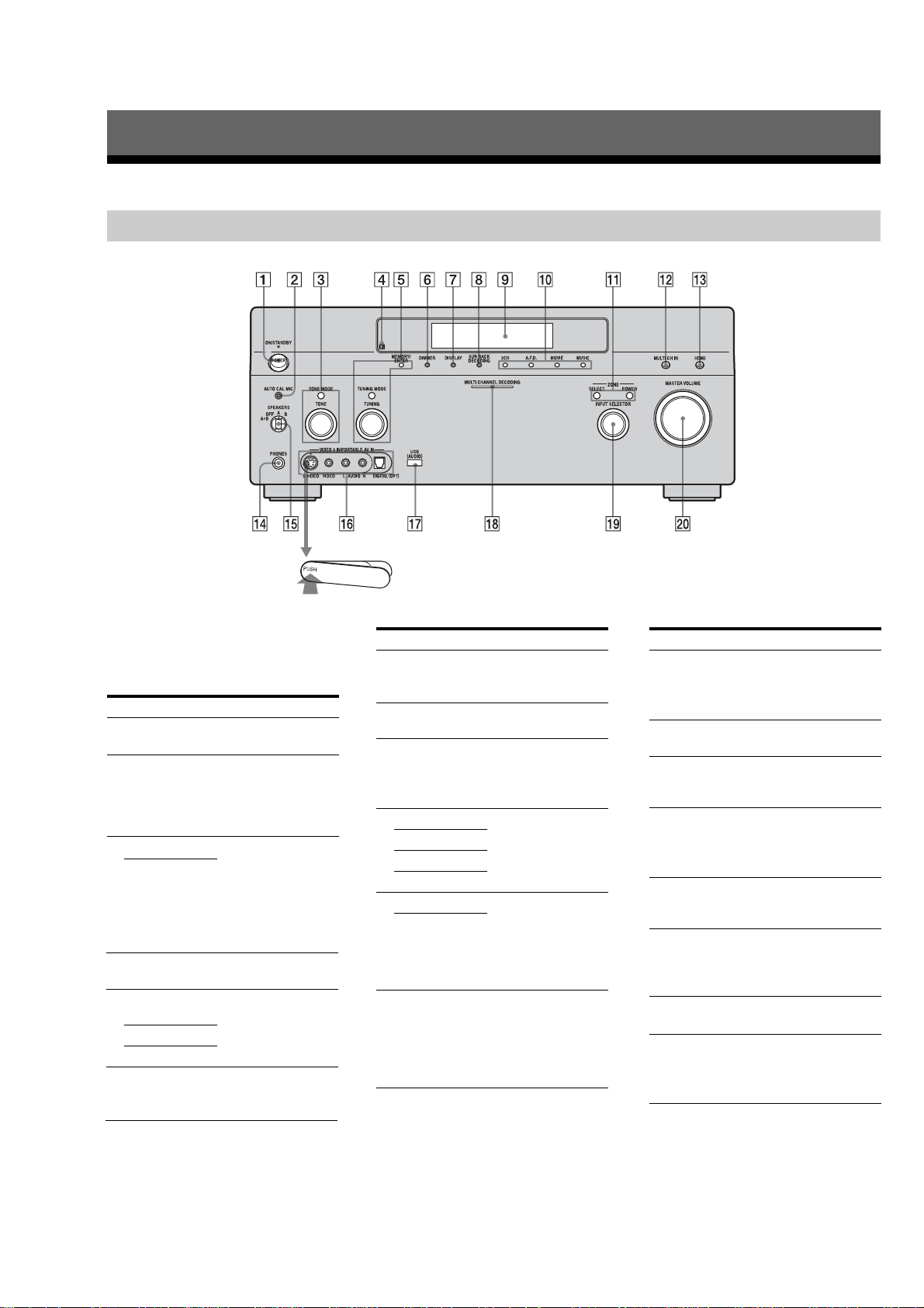
Getting Started
Description and location of parts (AEP and UK models)
Front panel
STR-DA5200ES
To remove the cover
Press PUSH.
When you remove the cover, keep it out of
reach from children.
Name Function
A POWER Press to turn the
B AUTO CAL MIC
jack
C TONE MODE Adjusts FRONT B ASS
TONE
D Remote sensor Receives signals from
E MEMORY/
ENTER
TUNING MODE
TUNING
F DIMMER Press to adjust
receiver on or off.
Connects to the
supplied optimizer
microphone for the
Digital Cinema Auto
Calibration function.
and FRONT TREBLE.
Press TONE MODE
repeatedly to select
BASS or TREBLE,
then turn TONE to
adjust the level.
remote commander.
Press to operate a tuner
(FM/AM).
brightness of the
display.
Name Function
G DISPLAY Press to select
H SUR BACK
DECODING
I Display
window
J 2CH Press to select sound
A.F.D.
MOVIE
MUSIC
K POWER Press SELECT
SELECT
L MULTI CH IN Press to select the audio
information displayed
on the display.
Press to activate SB
Decoding.
The current status of
the selected component
or a list of selectable
items appears here.
field.
repeatedly to select
zone 2 or zone 3, then
press POWER to
output signals to the
selected zone.
input signal from the
component connected
to the MULTI
CHANNEL INPUT
jack.
Name Function
M HDMI Press to select input
N PHONES jack Connects to
O SPEAKERS
(OFF/A/B/A+B)
P VIDEO 3 IN/
PORT ABLE AV
IN jacks
Q USB (AUDIO)
jack
R MULTI
CHANNEL
DECODING
lamp
S INPUT
SELECTOR
T MASTER
VOLUME
source from the
component connected
to the HDMI IN jack.
headphones.
Switch to OFF, A, B,
A+B of the front
speakers.
Connect to a portable
audio/video component
such as a camcorder or
video game.
Connects to a portable
audio product with a
USB jack.
Lights up when multichannel audio signals
are decoded.
Turn to select the input
source to play back.
Turn to adjust the
volume level of all
speakers at the same
time.
15
Page 16
STR-DA5200ES
Rear panel
A AUDIO INPUT/OUTPUT section
AUDIO IN/
OUT jacks
MULTI
CHANNEL
INPUT jacks
PRE OUT jacks Connect to an
Connect to a tape
deck, MD deck or
DAT player, etc.
Connect to a Super
Audio CD player or
DVD player with an
analog audio jack for
7.1 channel or 5.1
channel sound.
external power
amplifier.
B DIGITAL INPUT/OUTPUT section
OPTICAL IN/
OUT jacks
COAXIAL IN
jacks
HDMI IN/OUT
jacks
Connects to a DVD
player, Super Audio
CD player, etc. The
COAXIAL jack
provides a better
quality sound.
Connects to a DVD
player, or a satellite
tuner. An image and
the sound are output
to TV or a projector.
C ANTENNA section
FM ANTENNA
jack
AM
ANTENNA
jack
Connects to the FM
wire antenna (aerial)
supplied with this
receiver.
Connects to the AM
loop antenna (aerial)
supplied with this
receiver.
D COMPONENT VIDEO INPUT/
OUTPUT section
COMPONENT
VIDEO (Y, P
, PR/CR)
C
B
INPUT/
OUTPUT
jacks*
Connect to a DVD
/
player, TV, or a
B
satellite tuner.
E RS-232C jack
Used for
maintenance and
service.
F Control jack for Sony equipment
and other external components
CTRL S IN/
OUT jacks
TRIGGER
OUT jacks
IR REMOTE
IN/OUT jacks
Connects to Sony
TV, DVD player or
VCR with
CONTROL S jack.
Connects to in terlock
on/off of th e power
supply of other 12V
TRIGGER
compliant
components, or the
amplifier/receiver of
zone 2 or zone 3.
Connects an IR
repeater.
G VIDEO/AUDIO INPUT/OUTPUT
section
AUDIO IN/
OUT jacks
VIDEO IN/
OUT jacks*
S VIDEO IN/
OUT jacks*
AUDIO IN/
OUT jack
VIDEO IN/
OUT jacks
VIDEO IN jack Connects to the
Connects to a VCR
or a DVD player etc.
Connects to the
component in zone 2
or zone 3.
component when
you want to watch in
PIP (Picture in
Picture) window.
H SPEAKERS section
Connects to speakers.
*You can watch the selected input image when you
connect the MONITOR OUT jack to a TV.
You can operate this receiver using a GUI
(Graphical User Interface).
16
Page 17
STR-DA5200ES
Remote commander
You can use the supplied remote RM-AAL006 to operate
the receiver and to control the Sony audio/video
components that the remote is assigned to operate.
RM-AAL006
Name Function
A AV ?/1 (on/
standby)
B ?/1 (on/
standby)
C
Input
buttons
D RECEIVER Press to enable the receiver operation.
Press to turn on or off the audio/video
components that the remote is assigned to
operate.
If you press the ?/1 (B) at the same time,
it will turn off the receiver and other Sony
components (SYSTEM STANDBY).
Note
The function of the AV ?/1
switch changes automatically each time
you press the input button (C).
Press to turn the receiver on or off.
If ZONE 2 or ZONE 3 is selected, only
the main receiver is turned on or off with
this button. To turn off all components
including an amplifier in zone 2 or zone
amplifier in zone 2 or zone 3, press ?/1
and AV ?/1 (A) at the same time
(SYSTEM STANDBY).
Press one of the buttons to select the
component you want to use. Press a
pink-labeled button after pressing SHIFT
(wj). When you press any of the input
buttons, the receiver turns on. The buttons
are factory assigned to control Sony
components. You can program the remote
to control non-Sony components
following the steps in “Programming the
“Programming the remote”.
Name Function Name Function
E ZONE 2
ZONE 3
F PIP Press SHIFT (wj), then press PIP to
MUSIC Press to select sound field.
RESOLUTION
G
MOVIE Press to select sound field.
H Numeric
buttons
I ENTER Press to enter the value after selecting a
MEMORY Press to store a station during tuner
J DISPLAY Press to select information displayed on
K
V/v/B/b
L OPTIONS Press to display and select items from
TOOLS Press to display and select items from the
M MENU Press to display the menu of the receiver
N ALBUM +/– Press to replay the previous scene or fast
O m/M
a)
x
a)
X
b)
H
./>
TUNING +/– Press to selest station.
P PRESET
b)
/–
+
TV CH +/– Press TV (wk) and then press TV CH+/−
Q F1/F2 Press TV (wk) and then press F1 or F2 to
TV/VIDEO Press TV/VIDEO and TV (wk) at the same
WIDE Press to select the wide picture mode.
MACRO1,
MACRO2
Press to enable the zone 2/zone 3
operation.
switchthe image of the PIP (Picture in
Picture) window.
The image will be changed as follows.
EXT VIDEO t ZONE 2 VIDEO t
OFF. You can also change the size of the
PIP window by pressing V/v.
Note
The HDMI video signals are not output
while the PIP window is displayed.
Press SHIFT (wj) then press
RESOLUTION repeatedly to change the
resolution of signals output from the
HDMI OUT or COMPONENT VIDEO
MONITOR OUT jack.
Press to
− preset/tune to preset stations.
− select track numbers of the CD player,
DVD player or MD deck. Press 0/10 to
select track number 10.
− select channel numbers of the VCR or
satellite tuner.
− After pressing TV (wk), press the
numeric buttons to select the TV
channels.
channel, disc or track using the numeric
buttons.
operation.
the display window, TV screen of the
VCR, satellite tuner, CD player, DVD
player, or MD deck.
After pressing MENU (qd) or TOP
MENU (qk), press V/v, B
or b to select the settings. Then press
to enter the selection.
option menus for receiver and DVD player.
option menus for DVD player, etc.
of a DVD player, TV, etc.
forward the current scene of the VCR or
DVD player.
a)
Press to operate the DVD player, CD
player, MD deck or
a)
Press to register FM/AM Radio stations or
to select preset stations.
to operate the TV, satellite tuner, VCR, etc.
select a component to operate.
• HDD recorder
F1: HDD
F2: DVD
• DVD/VHS combo player
F1: DVD
F2: VHS
at the same time to select the input signal
(TV input or video input).
Press RECEIVER (4) and then press
MACRO 1 or MACRO 2 to set up the
macro function.
tape deck, etc.
R TOP MENU Press to display the menu or on-screen
MENU Press to display the menus of the DVD
NIGHT
MODE
INPUT
MODE
S MUTING Press to silence the sound.
T MASTER
VOL +
TV VOL +/– Press TV (wk) and then press TV VOL +/−
U DISC SKIP Press to skip a disc when using a
V RETURN/
EXIT O
W ON SCREEN Press to turn the GUI display mode on or
X CLEAR Press to
>10 Press to select
D.TUNING Press to enter direct tuning mode.
Y A.DIRECT Press SHIFT (wj) then press A.DIRECT
2CH Press to select sound filed.
Z SLEEP Press SHIFT (wj) then press SLEEP to
A.F.D Press to select sound filed.
wj SHIFT Press to light up the button. It changes the
wk TV Press to enable the TV operation.
wl RM SET UP Press to set up the remote.
a)
See the table on page111 for information on the buttons that you
can use to control each component.
b)
The tactile dot is attached to these buttons (H, PRESET+).
Use as a mark of operation.
guide of the DVD player on the TV screen.
Then use V/v/B/b and
menu operations.
player on the TV screen. Then use
V/v/B/b and
operations.
Press RECEIVER (4) and then press
NIGHT MODE to activate the NIGHT
MODE function.
Press RECEIVER (4) and then press
INPUT MODE to select the input mode
when the same components are connected
to both digital and analog jacks.
Press to adjust the volume level of all
b)
/–
speakers at the same time.
to adjust the volume level of the TV.
multi-disc changer.
Press to return to the previous menu or exit
the menu while the menu or on-screen
guide of the VCR, DVD player, or satellite
tuner is displayed on the TV screen.
off. Press MENU (qd) to display the
menu when “GUI ON” appears on the
display.
− clear a mistake when you press the
incorrect numeric button.
− return to continuous playback, etc. of
the satellite tuner or DVD player.
− track numbers over 10 of the VCR,
satellite tuner, CD player or MD deck.
− channel numbers of the Digital CATV
terminal.
to switch the audio of the selected input
to analog signal without any adjustment.
activate the Sleep Timer function and the
duration which the receiver turns off
automatically.
changes the remote button function to
activate the buttons with pink printing.
Notes
• Some functions explained in this section may not work
on the model.
• The above explanation is intended to serve as an examp l e only.
Therefore, depending on the component, the above operation
may not be possible or may operate differently than described.
to perform
to perform a menu
17
Page 18
STR-DA5200ES
RM-AAU009
This remote is onl y for zone 2/zone 3
operations. You cannot control the main
receiver directly with this remote.
Operating the main receiver from
zone 2
Name Function
A ?/1 (on/
standby)
B Command
mode
buttons
C Input
buttons
Press to turn a receiver in zone 2
or zone 3 on or off.
Press to select the command
mode of the remote.
Press one of the buttons to
select the component you want
to use. When you press any of
the input buttons, the receiver
turns on. The butto ns are
factory assigned to control Sony
components as f ollows.
Button Assigned Sony
VIDEO 1 VCR (VTR mode 3)
VIDEO 2 VCR (VTR mode 1)
VIDEO 3 VCR (VTR mode 2)
DVDDVD player
TV/SAT TV tuner
TAPE/
CD-R
MD/DAT MD deck
SA-CD/CD Super Audio CD/CD
TUNER* Built-in tuner
SOURCE The cu rre nt input
*The setting cannot be changed.
component
Tape deck B
player
selected for the main
receiver
Operating the components
connected to the main receiver
from zone 2 or zone 3
Name Function
H Operation
buttons*
I CH/
PRESET/
D.SKIP
+/–*
*The function of these buttons switches
automatically each time you press the input
buttons C. The above explanation is intended to
serve as an example only. Therefore, depending
on the component, the above operation may not
be possible or may operate differently than
described.
The following table describes
the function of the buttons.
Button(s) Function
N Starts play . (Starts play
n Starts play on the
X Pauses play or
x Stops play.
./> Skips tracks.
m/M Go backward/forward.
on the front side of the
cassette.)
reverse side of the
cassette.
recording, and starts
recording when the
component is in
recording standby.
Press repeatedly to select a
preset station or channel. When
using a multi-disc changer,
press to skip a disc.
D MUTING Press to mute the sound.
E MASTER
VOL +/–
Press to adjust the volume level
for multi zone output.
F RM SET UP Press to change the cat egory of
the buttons.
G RM SET UP
indicator
Lights up when data is being
sent or when the remote button
assignment is being preset.
18
Page 19
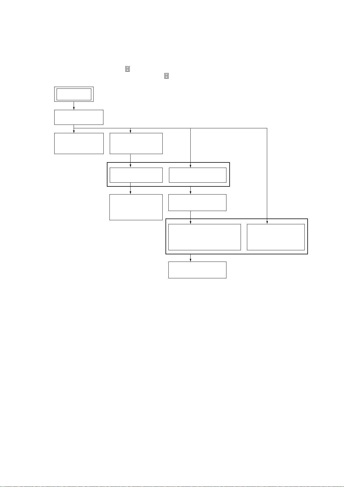
SECTION 3
DISASSEMBLY
• This set can be disassembled in the order shown below.
3-1. DISASSEMBLY FLOW
Note 1: The process described in can be performed in any order.
Note 2: Without completing the process described in , the next process can not be performed.
SET
3-2. CASE
(Page 20)
STR-DA5200ES
3-3. FRONT PANEL
ASSY
(Page 20)
3-4. S-VIDEO/CIS
BOARD
(Page 21)
3-7. VIDEO BOARD
(Page 22)
3-8. ZONE3/
SP TERMINAL
BOARD
(Page 23)
3-5. TUNER
(Page 21)
3-9. AUDIO BOARD
(Page 23)
3-10. DC-DC-HDMI BOARD/
POWER TRANSFORMER
(T01)
(Page 24)
3-11. MAIN BOARD
(Page 24)
3-6. E-VOLUME
BOARD
(Page 22)
19
Page 20
STR-DA5200ES
Note: Follow the disassembly procedure in the numerical order given.
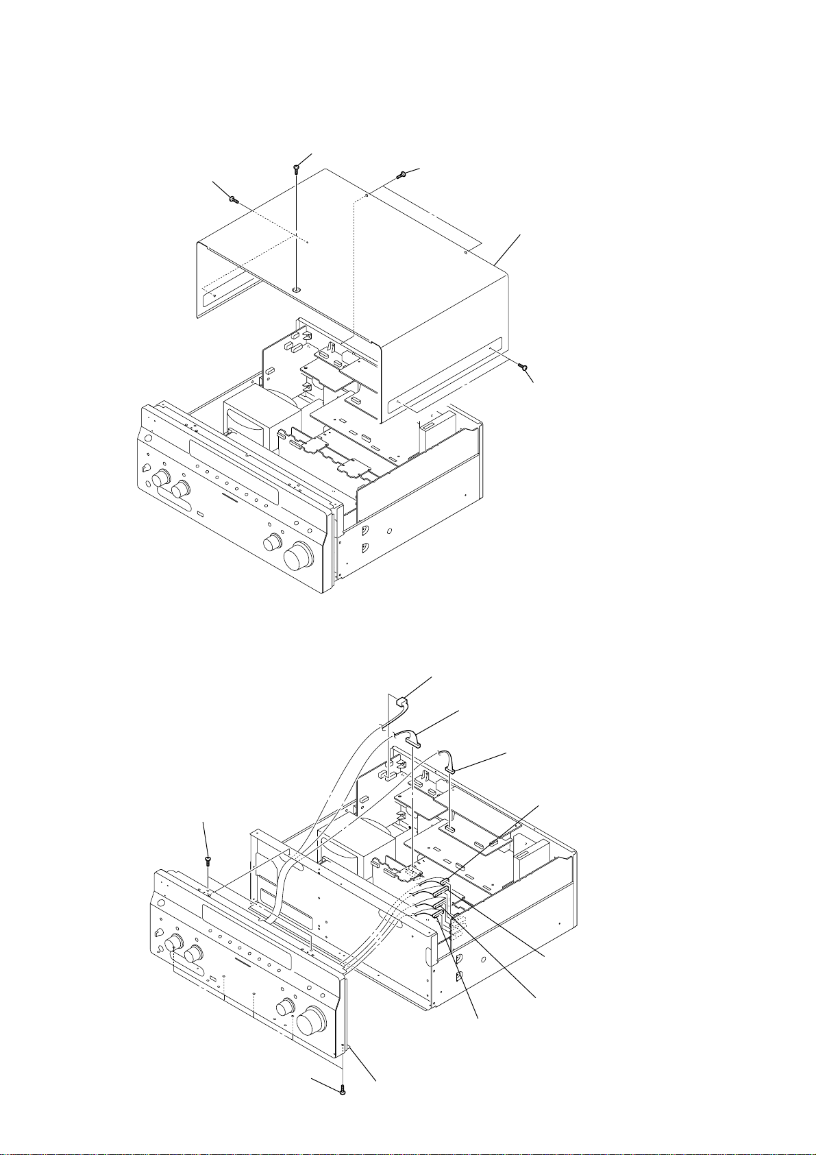
3-2. CASE
3
flat head screw
1
two screws (4 × 8)
2
two flat head screws
4
case
1
two screws (4 × 8)
3-3. FRONT PANEL ASSY
9
two screws
(BVTP3
×
8)
8
five screws
(BVTP3
1
connector
(CNP53)
2
connector
(CN606)
3
connector
(CNP6902)
4
connector
(CN2015)
5
connector
(CN2016)
6
connector
7
connector
(CN2030)
×
8)
0
front panel assy
(CN2014)
20
Page 21
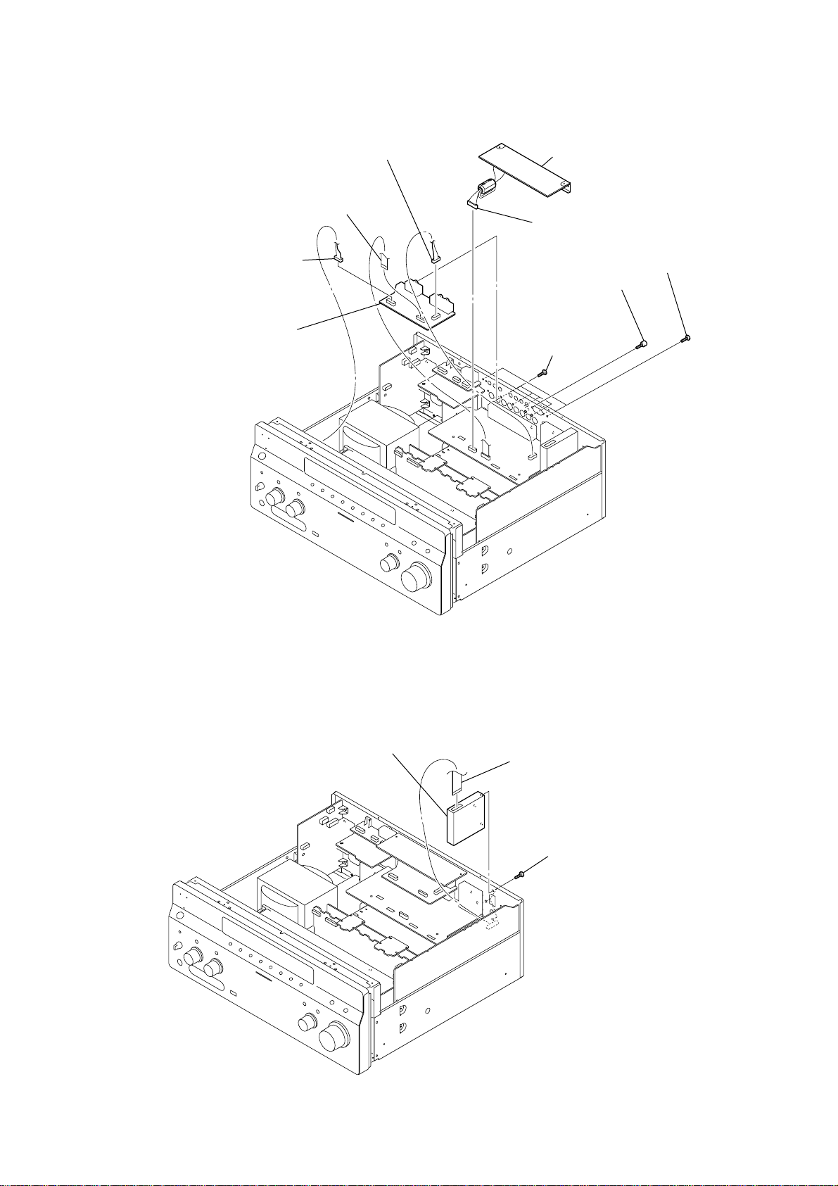
3-4. S-VIDEO/CIS BOARD
)
5
wire (flat type) (15 core)
(CNS6903)
7
connector
(CNP6902)
9
S-VIDEO board
6
connector
(CNP6901)
4
1
8
four screws
(BVTP3 × 8)
CIS board
connector
(CN6801)
2
two screws
STR-DA5200ES
3
two screws
×
(BVTP3
8
3-5. TUNER
3
tuner
1
wire (flat type) (11 core) (US, Canadian)
wire (flat type) (15 core) (AEP, UK)
2
three screws
(BVTP3
×
8)
21
Page 22
STR-DA5200ES
)
)
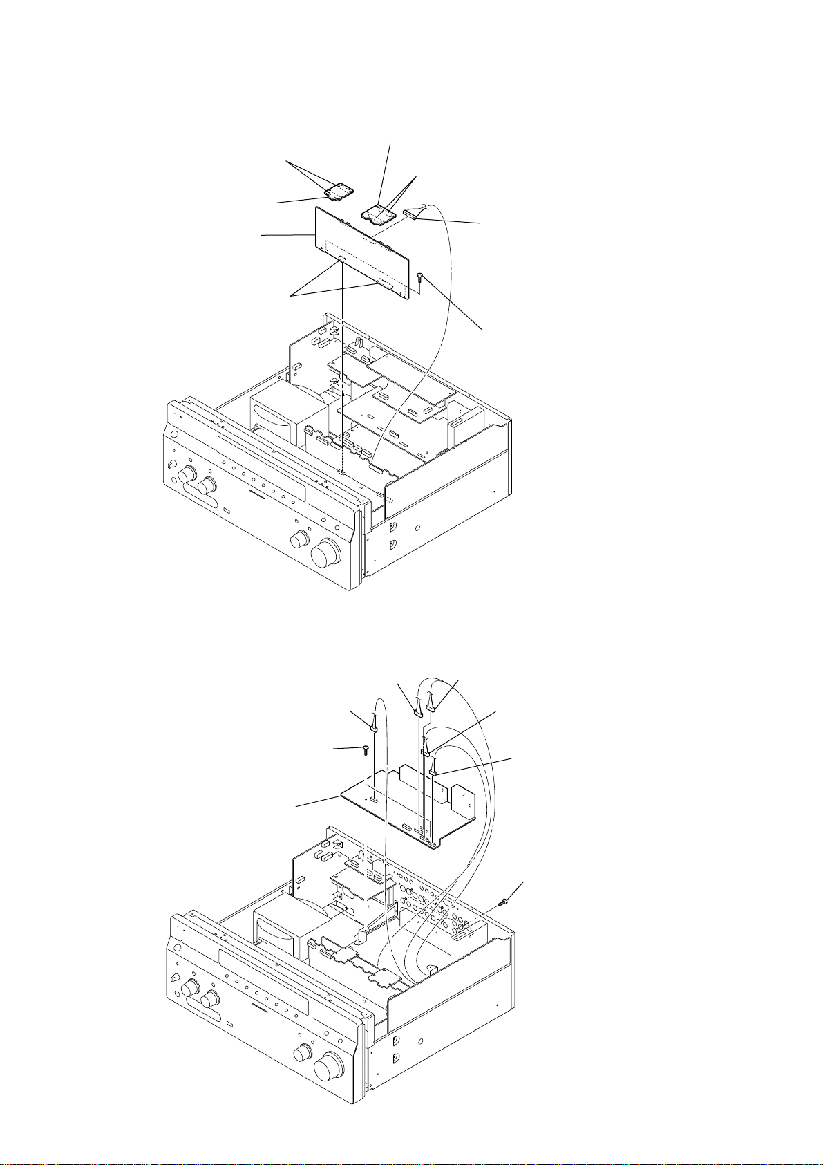
3-6. E-VOLUME BOARD
1
two connectors
(A CLASS AMP: CNS1502, E-VOLUME: CNS1202)
2
CONNECTOR L board
8
E-VOLUME board
6
two connectors
(CNS1203, 1204)
4
CONNECTOR R board
3
two connectors
(A CLASS AMP: CNS1501, E-VOLUME: CNS1201
5
connector
(CNP1208)
7
two screws
(BVTP3
×
8)
3-7. VIDEO BOARD
8
VIDEO board
6
two screws
(BVTP3
1
connector
(CN6805)
×
2
connector
(CN6808)
8)
3
connector
(CN6803)
4
connector
(CN6806)
5
connector
(CN6804)
7
six screws
(BVTP3
×
8
22
Page 23
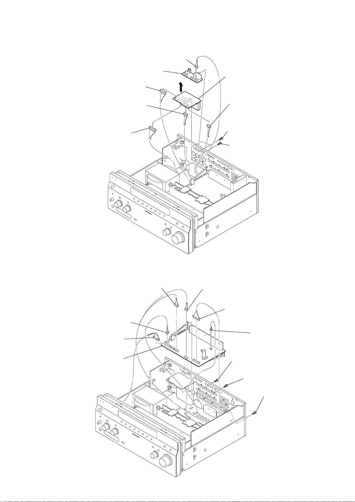
3-8. ZONE3/SP TERMINAL BOARD
d
)
1
3
ZONE3 board
connector
7
(CNP4102)
8
connector
(CNP4104)
9
connector
(CNP4101)
connector (CN610)
5
0
SP TERMINAL boar
6
connector
(CNP4103)
2
two screws
(BVTP3 × 8)
4
two screws
(BV/RING)
STR-DA5200ES
3-9. AUDIO BOARD
0
AUDIO board
2
1
connector
(CN606)
connector
(CN608)
3
connector
(CN603)
4
connector
(CN602)
5
connector
(CN601)
6
connector
(CNP401)
7
screw
(BVTP3
×
8)
8
seven screws
(BVTP3
9
×
8)
screw
(BVTP3
×
8
23
Page 24
STR-DA5200ES
3-10. DC-DC-HDMI BOARD/POWER TRANSFORMER (T01)
qs
power transformer (T01)
qa
1
4
2
three screws
(BVTP3
6
connector
(CNP1451)
connector
(CN7020)
connector
(CN7052)
×
8)
5
DC-DC-HDMI board
7
connector
(CNP1404)
3
two screws
(BVTT4
×
8)
0
two screws
(BVTT4
×
8)
8
connector
(CNP1403)
9
connector
(CNP02)
3-11. MAIN BOARD
1
3
2
connector
(CN1902)
connector
(CN1410)
connector
(CNP54)
0
two screws
(BVTP3 × 8)
4
connector
(CNP1003)
5
connector
(CNP1001)
qa
MAIN board
8
three screws
(BV/RING)
9
four screws
(BVTP3 × 8)
24
7
connector
(CN2021)
6
connector
(CN2012)
Page 25

SECTION 4
TEST MODE
STR-DA5200ES
TUNER FACTORY PRESET MODE
All preset contents are reset to the default setting.
Procedure:
1. While pressing the [2CH] and [TUNING MODE] buttons, press
the [POWER] button to turn on the main power.
2. The message “Factory Preset” appears and the present contents
are reset to the default values.
MEMORY CLEARING MODE
All preset contents are cleared when this mode is activated. Use
this mode before returning the product to clients upon completion
of repair.
Procedure:
1. While pressing the [TONE MODE] and [MULTI CH IN] buttons,
press the [POWER] button to turn on the main power.
2. The message “MEMORY CLEARING...” appears and the
memories are reset to the default values.
3. When done, the message “MEMORY CLEARED !” appears.
SWAP MODE
Procedure:
1. While pressing the [2CH] and [MULTI CH IN] buttons, press
the [POWER] button to turn on the main power.
2. The message “SWAP MODE !” appears.
FLUORESCENT INDICATOR TUBE PATTERN
CHECK MODE
All fluorescent segments are tested. When this test is activated, all
segments turn on at the same time, then each segment turns on one
after another.
Procedure:
1. While pressing the [MOVIE] and [MULTI CH IN] buttons, press
the [POWER] button to turn on the main power.
2. All segments and all LEDs turn on.
SOUND FIELD CLEAR MODE
The preset sound field is cleared when this mode is activated. Use
this mode before returning the product to clients upon completion
of repair.
Procedure:
1. While pressing the [MUSIC] button, press the [POWER] button
to turn on the main power.
2. The message “S. F. Initialize” appears and initialization is
performed.
COMMAND MODE CHANGE MODE
The command mode of the remote-commander which this set
receives can be changed.
Procedure:
1. While pressing the [2CH] button, press the [POWER] button to
turn on the main power.
2. Either the message “COMMAND MODE [AV1]” or
“COMMAND MODE [AV2]” appears. Select the desired
mode.
SF LOCK ON/OFF CHANGE MODE
Procedure:
1. While pressing the [MUSIC] and [MULTI CH IN] buttons, press
the [POWER] button to turn on the main power.
2. Either the message “OFF” or “ON” appears.
RDS AUTOBETICAL MODE
(AEP AND UK MODELS)
Procedure:
1. While pressing the [MEMORY/ENTER] button, press the
[POWER] button to turn on the main power.
2. The message “Autobetical Select” appers and scans and stores
all the FM and FM RDS station in the broadcast area.
XM FACTORY TEST MODE
(US AND CANADIAN MODELS)
Mode to confirm operation of XM. Doing display of ID of XM
antenna and output of audio signal that XM antenna generates, it is
confirmed that there are no probrems in the communication of the
XM antenna and the tranmission of the audio signal.
Procedure:
1. The XM antenna was connected, while pressing the
[CATEGORY --] and [MEMORY/ENTER] buttons, press the
[POWER] button to turn on the main power.
2. Whenever the [DISPLAY] button is pressed, the output of the
audio signal of 1 kHz L/R, 20 Hz L/R, 5 kHz L/R, muting, 1
kHz L and 1kHz R are switched.
TUNER AM STEP CHANGE (9 kHz/10 kHz) MODE
(US AND CANADIAN MODELS)
Either the 9 kHz step or 10 kHz step can be selected for the AM
channel step.
Procedure:
1. While pressing the [TUNING MODE] button, press the [POWER]
button to turn on the main power.
2. Either the message “AM 9kHz Step” or “AM 10kHz Step”
appears, Select the desired step.
25
Page 26
STR-DA5200ES
SPECIAL MENU MODE
Procedure:
1. Press the [POWER] button to turn on the main power , then while pressing the [TONE MODE] button, press the [A.F.D.], [2CH], [MUSIC],
[MOVIE] button in order.
2. The message “MENU SPECIALIZED!” appears.
3. Each time the M m button of the remote commander is pressed, the item is switched in order as follows.
4. To release from this mode, while pressing the [TONE MODE] button, press the [A.F.D.], [2CH], [MUSIC], [MOVIE] button in order again.
5. The message “MENU SPECIALIZED OFF” appears.
Items
RAM watch menu
Protector on/off
Model version display
Model/destination change
Video Ucom version display
FAROUDJA version display
USB Ucom version display
USB LIB version display
XM TUNER version display
FM/AM tuner version display
Auto cal mic test
FL display fonts test
FL display test
Audio swap
Video factory menu
Video calibration
(Video factory menu)
XXX
PROTECTOR ON/OFF [XXX]
##### *** vX. XX @@@@
MODEL [##### * * * *] X X
Video Ucom Ver X. XX
FAROUDJA Ver X. XX
USB Ucom Ver X. XX
USB LIB Ver X. XX
XM Tuner Ver X. XX
FM/AM Tuner Ver X. XX
SPEAKER OUT [XXXXX]
FL FONT 0x ** = [X]
ALL ON
SWAP [XXXXXXXXXXX]
<VIDEO FACTORY MENU>
V.CAL START? N:#, P:@
Please Check V.Input
Display
Remark
XXX: For monitor of various internal RAM (for design evaluation)
XXX: ON or OFF
(switching with M m button of the remote commander)
#####: model
***: destination
X.XX: system controller software version
@@@@: Sum value of flash memory in the main system controller
#####: model, ****: destination, XX: at or fx
(switching with M m button of the remote commander)
X.XX: Video Ucom software version
X.XX: FAROUDJA (Video Processor) software version
X.XX: USB Ucom controller software version
X.XX: USB function control library version
X.XX: XM tuner controller software version
X.XX: FM/AM tuner controller software version
XXXXX: Selection of speaker output audio
[SOURCE]: nomally mode, [MIC]: mode that output audio from mic from
speaker
**: 20 to FE, X: character (switching with M m button of the remote
commander)
Each time DISPLAY button to change as follows.
all on → test pattern 1 → test pattern 2 → all off → all on
Switching with M m button of the remote commander
Menu mode to enter video calibration menu and DDR access check menu
If the [ENTER] button of the remote commander is pressed, entering the
menu, and operating two the following menu become possible
Procedure:
1. “DVD” is selected.
2. Connect a color pattern generator to the EXT VIDEO VIDEO IN jack
(J6905) on the S-VIDEO board, DVD S VIDEO IN jack (J6902) on the SVIDEO board, COMPONENT VIDEO DVD IN jack (J6102) on the VIDEO
board and DVD VIDEO IN jack (J6401) on the VIDEO board.
3. Input 100% color bars signal from the color pattern generator.
DDR access check
(Video factory menu)
DSP halt
DSP RAM
26
DDR CHECK [XXX]
DSP HALT [XXX]
[*****]=XXXXXXXX
Menu that measures individual difference of hardness by automatic operation
in pressing the [ENTER] button of the remote commander, and corrects
reference value.
In a measurement once, only one of NTSC/PAL can be measured
”V.CAL START?” at display
#: X (NTSC measurement incompletion) or O (NTSC measurement completion)
@: X (P AL measur ement incompletion) or O (PAL measurement completion)
”Please Check V.Input” at display
Video signal necessary for the measurement while measuring it last time was
not detected and it became an error
Confirm the input of the video of the terminal connection etc. , and measure
the [ENTER] button of the remote commander again pressing
XXX: Time to do access check on DDR (for design evaluation)
XXX: ON or OFF (switching with M m button of the remote commander)
Mode not to send DSP host code, and to make only decipherment done
Mode that refers to internal RAM of DSP (for design evaluation)
Page 27
STR-DA5200ES
Items
DSP V ersion display
Volume value display (FL/FR)
Volume value display (SL/SR)
Volume value display (CT/SW)
Volume value display
(SBL/SBR)
DAC mute information disclosure
1
DAC mute information disclosure
2
EERROM debug
Super reset
2nd volume value display
FL display duty change
Stop clock
Display
DSP Ver S: ***, P: XXX
FL**** FR XXXX
SL**** SR XXXX
CT**** SW XXXX
SBL**** SBR XXXX
DAC MUTE U XXXXXXXX
DAC MUTE L XXXXXXXX
EEPROM [****] FR XX
SUPER RESET [XXX]
2nd VOLUME XXX
DARK OUT DUTY [XXX%]
STOP CLK [XX] [XX] [XX]
Remark
***: DSP decoder patch version
XXX: DSP post process version
****: Front L-ch volume value
XXXX: Front R-ch volume value
****: Surround L-ch volume value
XXXX: Surround R-ch volume value
****: Center volume value
XXXX: Sub woofer R-ch volume value
****: Surround back L-ch volume value
XXXX: Surround back R-ch volume value
Display of module information to demand muting in system controller (for
design evaluation)
Display of module information to demand muting in system controller (for
design evaluation)
****: EEPROM address
XX: EEPROM data (switching with M m button of the remote commander)
Not used for the servicing
If super reset is performed, “up convert signal level adjustment” will also be
initialized
When EEPROM initialization is required, perform the “all clear mode”
XXX: 2nd room volume value (00 to ∞)
XXX: Duty value of FL display (0% to 100%)
(switching with M m button of the remote commander)
Value of register related to clock of system controller display mode (for
design evaluation)
27
Page 28
STR-DA5200ES
)
SECTION 5
ELECTRICAL ADJUSTMENTS
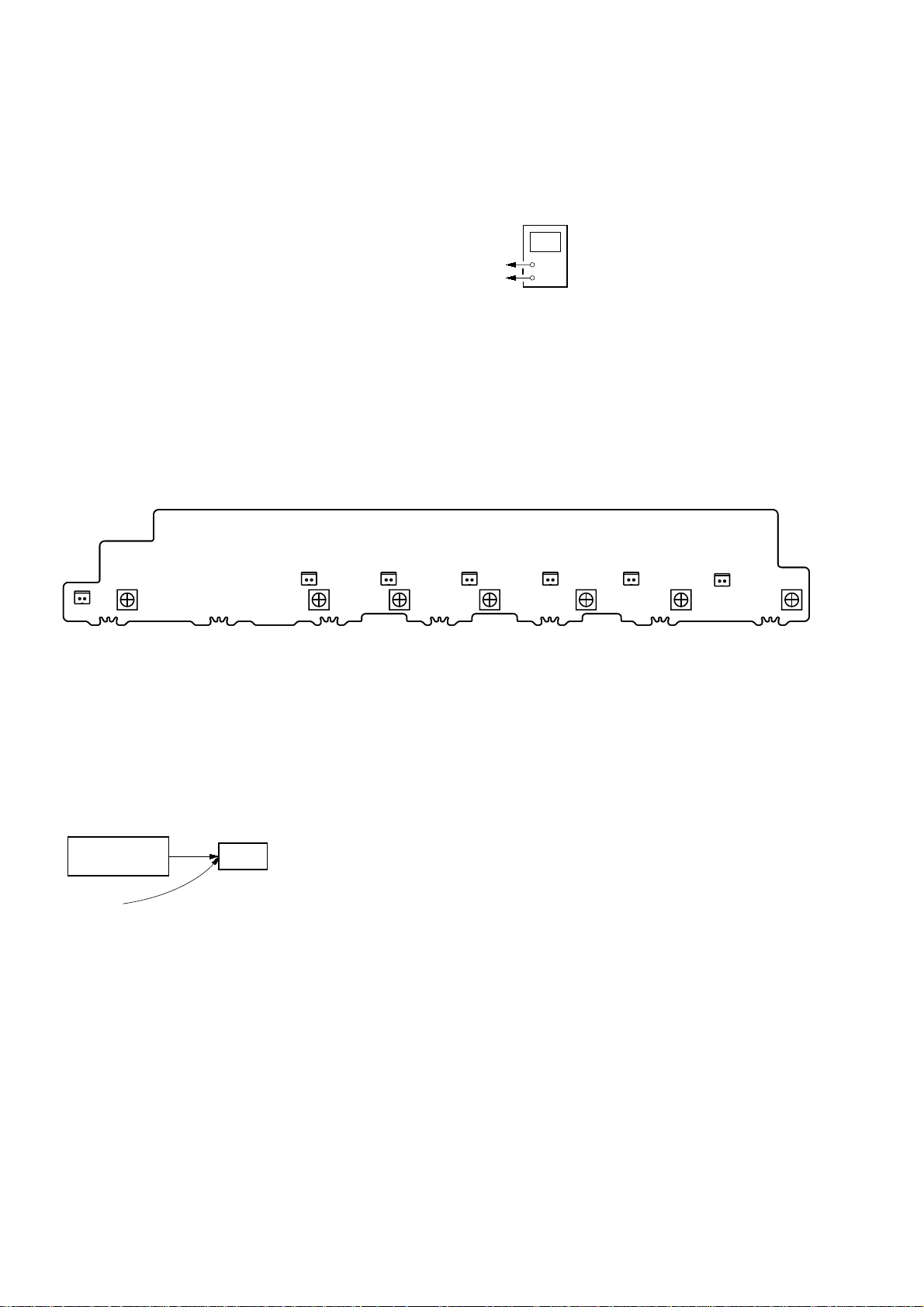
BIAS ALIGNMENT ADJUSTMENT
Note: Afer 10 minutes or more have passed since the power supply was
turned on, this adjustment is done.
Connection:
CNP1502 (CNP1552, CNP1602, CNP1702, CNP1752, CNP1802, CNP1852) pin
CNP1502 (CNP1552, CNP1602, CNP1702, CNP1752, CNP1802, CNP1852) pin
Procedure:
1. Connect a digital voltmeter to the CNP1502 (CNP1552,
CNP1602, CNP1702, CNP1752, CNP1802, CNP1852) on the
BIAS board.
2. Press the [POWER] button to turn on the main power.
3. Adjust the RV1501 (RV1551, RV1601, RV1701, RV1751,
RV1801, RV1851) so that the digital voltmeter reading is 5 mV
to 20 mV.
Adjustment and Connection Location:
digital voltmeter
+
1
–
2
– BIAS Board (Component Side) –
CNP1702
CNP1752
2
RV1751
1
RV1701
1
2
2
RV1551 RV1501 RV1601
VIDEO CALIBRATION ADJUSTMENT
Adjustment to decide the standard of the video input signal.
Note: After replacing HDMI board, or after “SUPER RESET” of the special
menu mode is executed, perform this adjustment.
Connection:
color pattern
generator
color bars 100%
S-VIDEO board EXT VIDEO VIDEO IN jack (J6905)
VIDEO board COMPONENT VIDEO DVD IN jack (J6102
DVD S VIDEO IN jack (J6902)
DVD VIDEO IN jack (J6401)
Procedure:
1. “DVD” is selected by using [INPUT SELECTOR] jog.
2. Connect a color pattern generator to the EXT VIDEO VIDEO
IN jack (J6905) on the S-VIDEO board, DVD S VIDEO IN
jack (J6902) on the S-VIDEO board, COMPONENT VIDEO
DVD IN jack (J6102) on the VIDEO board and D VD VIDEO
IN jack (J6401) on the VIDEO board.
3. Input NTSC color bars signal from the color pattern generator.
4. Press the [POWER] button to turn off the main power
set
CNP1502CNP1552 CNP1602 CNP1852 CNP1802
1
1
2
1
2
1
2
RV1851 RV1801
5. While pressing the [TUNING MODE], [MUSIC] and [MULTI CH
IN] buttons, press the [POWER] button to turn on the main
power. It enters the test mode, and display as below.
V.CAL START? N:#, P:@
#: X (NTSC measurement incompletion) or
O (NTSC measurement completion)
@: X (PAL measurement incompletion) or
O (PAL measurement completion)
When “Please Check V.Input” is displayed, Video signal
necessary for the measurement while measuring it last time
was not detected and it became an errorConfirm the input of
the video of the terminal connection etc., and measure the
[MEMORY/ENTER] button again pressing.
6. When the [MEMORY/ENTER] button is pressed, the adjustment
is automatically completed, and result is written in the
EEPROM.
7. Input PAL color bars signal from the color pattern generator.
8. Perform step 4 to 6.
1
2
28
Page 29
SECTION 6
DIAGRAMS
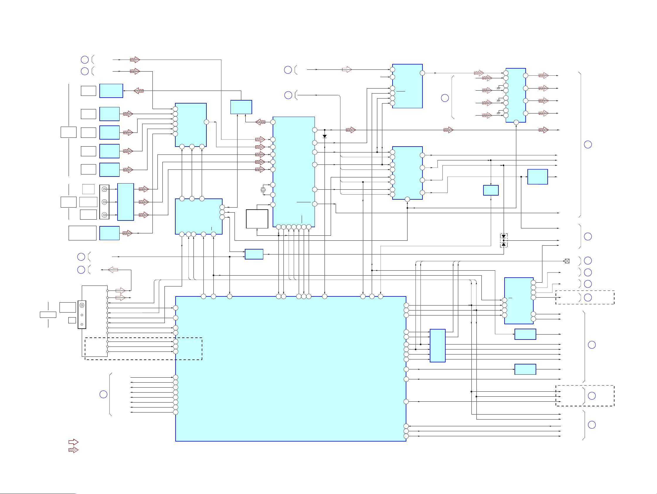
6-1. BLOCK DIAGRAM – CONTROL Section –
STR-DA5200ES
ANTENNA
(Page 31)
(Page 33)
DIGITAL
OPTICAL
DIGITAL
COAXIAL
(Page 33)
(Page 34)
FM 75Ω
COAXIAL
VIDEO 3 IN/
PORTABLE AV IN
DIGITAL (OPT)
AM
HDMI_SPDIF
1
USB SPDIF
2
MD/DAT
OUT
VIDEO 1
IN
VIDEO 2
IN
TV/SAT
IN
MD/DAT
IN
DVD
IN
TAPE/CD-R
IN
SA-CD/CD
IN
3
4
RDS SIGNAL
(AEP, UK)
(Page 35)
OPTICAL
TRANSCEIVER
IC2004
OPTICAL
RECEIVER
IC2001
OPTICAL
RECEIVER
IC2002
OPTICAL
RECEIVER
IC2003
OPTICAL
RECEIVER
IC2005
J2001
OPTICAL
RECEIVER
IC707
USB ERROR
TU-L
TUNER
TUN-LCH
TUN-RCH R-CH
COM1 CLK
DO
COM1 DATA
CE
MUTE
TUNED
STEREO
RDS DATA
RDS-CLK
5
PREOUT-RY
• R-CH is omitted due to same as L-CH.
• SIGNAL PATH
: AUDIO (ANALOG)
: AUDIO (DIGITAL)
WAVE
SHAPER
IC2007
HPSW
REAR-RY
SB-RY
C-RY
SP-B-RY
SP-A-RY
HP-RY
COM1-CLK
COM1-DAT
INPUT SELECTOR
IC2009
14 D5
1D3
3D1
2D2
4D0
15 D4
A0
10
11
5
4
QE
DATA DECODER
S-IN
QB
11
14
1
COM1-CLK
COM1-DAT
7 TUNER DO
6 TUNER LAT
8 TUNED
9STEREO
10 RDS DATA
100 R DS CLK
58 RDS SIGNAL
H.P. IN
153
REAR-RY
112
SB-RY
111
C-RY
110
SP-B-RY
109
SP-A-RY
107
PREOUT RY
76
HP-MUTE
92
5Y
A1
A2
9
6
QF
QG
IC2012
CLK12LAT13OE
72
D595 LAT
QH
71
D595 OE
7
15QA
3QD
DIGITAL OUT
SWITCH
IC2008
101
USB ERROR
X2001
24.576MHz
PLL CLOCK
SELECT
Q2002, 2004,
Q2005
AND GATE
IC2063
(Page 34)
(Page 31)
7
8
DIGITAL AUDIO INTERFACE
1RXOUT
10 RX6/UI
2RX0
8RX4
5RX3
4RX2
29
XIN
XOUT28
13 LPF
RERR
38
37DO36
COM1-DAT
33
32
DIR DO
DIR ERROR
SYSTEM CONTROLLER
IC2054 (1/3)
2CH-L
HDMI_BCK, HDMI_LRCK,
HDMI_ERROR, HDMI_MCK
IC2006
CE
CKST
XMODE
CL
DI
40
39
34
41
COM1-CLK
31
34
30
DIR CE
DIR CKST
DIR XMODE
A/D CONVERTER
IC2024
1
VINL
15
11
10
14
13
11
10
164
COM1 DATA 84
COM1 CLK 82
FSRATE
O595 LAT 73
V595 LAT 78
V595 OE 77
COM2 DATA
COM2 CLK 85
PREVOL LAT 75
FUNC LAT 74
D.MIX-LAT
DSP SPICLK 14
2
VINR
SCKI
7
PDWN
BCK
LRCK
INPUT SELECTOR
IC2018
A3
B3
A2
B2
2
A0
3
B0
5
A1
6
B1
R-CH
21RDATA
D2002
27XMCK
17RBCK
20RLRCK
16RMCK
33AUDIO/VO
11
DATA0
HDMI_BCK
HDMI_LRCK
HDMI_ERROR
HDMI_MCK
67
IH ERROR
40
A/D(SB) RESET
106
90SB-POW
39DAC DO
38DAC LAT
37AD/DA RESET
86
S
1
DOUT
Y3
Y2
Y0
Y1
COM2-CLK
12
12
9
4
7
COM2-DAT
9
(Page 31)
BUFFER
IC2046
V595 OE
V595 LAT
COM1-CLK
COM1-DAT
BUFFER
IC2017
INPUT SELECTOR
IC2019
2
A0
Y0
3 B0HDMI_DATA1
5A1
6 B1HDMI_DATA2
11 A2
10 B2HDMI_DATA3
14 A3
13 B3HDMI_DATA4
S
1
D2004
DATA DECODER
IC2044
13 OE
14 S-IN
11 CLK
12 LAT
LEVEL SHIFT
IC2015
LEVEL SHIFT
IC2016
4
SHIFT
REGISTER
IC2022
7
QH
QC 2
QD 3
QB 1XM POW
QE 4
QF 5
SI_B
SI_CY1 7
SI_DY2 9
SI_EY3 12
SI_A
DPBCK
DPLRCK
DIR-RERR
DPFSCK
DIR_NONAU
D/A MCK
ERR
ANA/DIGI
XM/H_SEL
V POWER
2ND-RY
3RD-RY
EXT-LAT
AUCOM-DATA
AUCOM-CLK
PREVOL-LAT
FUNC-LAT
D.MIX-LAT
MIC
COM1_DATA
COM1_CLK
XM_DACLAT
COM1_DATA
COM1_CLK
DAC DO
DAC LAT
AD/DA RESET
CTL
(Page 30)
10
(Page 30)
11
12
(Page 37)
13
(Page 31)
(Page 38)
14
(Page
40
(US, Canadian)
15
(Page 34)
16
(US, Canadian)
17
(Page 30)
38)
(Page
33)
STR-DA5200ES
2929
Page 30
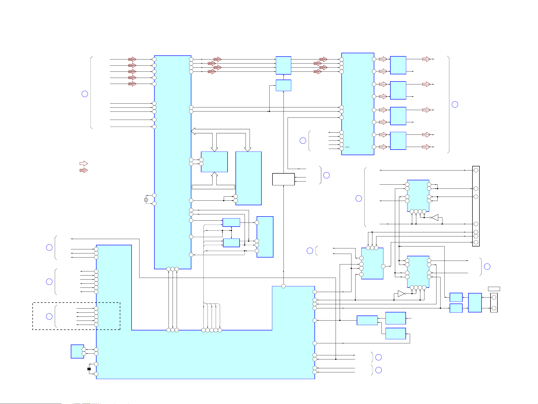
STR-DA5200ES
6-2. BLOCK DIAGRAM – DSP Section –
(Page 32)
(Page 33)
(Page 33)
(US, Canadian)
18
19
20
(Page 29)
STOP
GUI_TX
GUI_RX
GUI_BUSY
USB DI
USB DO
USB CONNECT DET
USB RESET
USB UART TX
USB UART RX
XM_IUART_TX
XM_UART_RX
XM_COMMAND
XM_REQ
XM RESET
EEPROM
IC2055
SI_A
SI_B
SI_C
SI_D
SI_E
10
DPBCK
DPLRCK
DIR-RERR
DPFSCK
DIR_NONAU
• R-CH is omitted due to same as L-CH.
• SIGNAL PATH
: AUDIO (ANALOG)
: AUDIO (DIGITAL)
122
GUI TX
123
GUI RX
124
GUI BUSY
171
USB DI
174
USB DO
127
CONNECT DET
172
USB RESET
128
USB UART TX
129
USB UART RX
119
XM UART TX
120
XM UART RX
170
XM COMMAND
169
XM REQ
121
XM RESET
167
5
SDA
SCL
X2004
12.5MHz
6
EEPROM SDA
168
EEPROM SCL
143
X-OUT
141
X-IN
X1
25MHz
78
DPSIA
DPSIB
79
80
DPSIC
DPSID
81
82
DPSIE
89
DPBCK
88
DPLRCK
16
DIR-ERR
94
DPFSCK
97
XNONAUDIO
143
XTAL
142
CLKIN
DSP
IC2
DPSOA
DPSOB
DPSOC
DPSOD
DPDVBCK
DPDVLRCK
SPICLK
XSF_CE
SPI_MAS
XSPIDS
INT_REQ15XRESET
122
121
13
99
12
DSP INT
DSP RESET
DSP SPIDS (LAT)
XWR
XRD
ALE
MOSI
MISO
64
65
70
71
87
86
AD0 – AD15
35
391741
40
125
127
98
63
126
DSP_SPICLK
118
SYSTEM CONTROLLER
DATA & ADDRESS BUS
AD0 – AD15
XWE
S-RAM
XOE
IC7
A0 – A18
ADDRESS BUS
SF_CPU_CE
SF_DSP_MAS
DSP_SPICLK
DSP_MOSI
DSP_MISO
DSP_MOSI
DSP_MISO
SF_CPU_CE
21
117
116
DSP CLK
DSP MISO
DSP MOSI
SF CPU CE
IC2054 (2/3)
A0 – A15A16 – A18
FLIP-FLOP
IC4
SWITCHING
IC5
SF_DSP_MAS
22
SF DSP MAS
ADDRESS LATCH
48
1LE
25
2LE
AD0 – AD15
IC6
SERIAL FLASH
IC3
1
CE#
6
SCK
5
SI
2
SO
MUTING
IC2035
MUTING
CONTROL
IC2036
SYSTEM MUTING
SWICTH
Q2006, 2007
44
MUTE
17
(Page 29)
(Page 32)
POWER RY2
4/8RERAY
PROTECTOR
AD/DA RESET
D/A MCK
ERR
ANA/DIGI
22
STOP
DAC DO
COM1_DATA
MD3 (GUI)
GUI_RST
173GUI_RST
138MD2
125FLASH SI
126FLASH SO
144XRESET
91RST-TRG
148
108
157
113
11
45 DATA1
46 DATA2
47 DATA3
31 DATA4
40 BCK
41 LRCK
38 SCKI
33 MDO
34 MDI
35 MCCOM1_CLK
36 MLDAC LAT
37 RST
(Page 29)
(Page 33)
D/A CONVERTER
IC2034
21
4ZC
13 1X
12 0X
15 YC
MULTIPLEXER
RESET SWITCH
IC2057
POW-RY
STOP
4-8RY
PROTECTOR
14VOUT1
13VOUT2
12VOUT3
11VOUT4
16VOUT7
20VOUT8
10VOUT5
USB-RST
USB-SO
USB-SI
USB-MD
11A9
C
IC2420
LOW-PASS
FILTER
IC2043
LOW-PASS
FILTER
IC2042
LOW-PASS
FILTER
IC2037
LOW-PASS
FILTER
14XC
RESET SIGNAL
GENERATOR
RESET SIGNAL
(Page 38)
(Page 38)
IC2040
IC2051
BUFFER
IC2056
Q2435
9VOUT6
10
B
25
26
R-CH
R-CH
R-CH
SWITCHING
IC704
12 4A
93A
62Y
31Y
11G134G42G10
SWITCHING
IC2421
52A
21A 31Y
83Y 93A
11 4Y 124A
4G
42G10
11G13
STB+3.3V
D/A-L
D/A-SL
(Page 34)
23
D/A-SBL
D/A-C
D/A-SW
CN713
(FOR SERVICE)
4 USB RESET
114Y
83Y
52A
21A
3G
Q712
62Y
5SO
6SI
7MD1 (USB)
9MD3 (HDMI)
8MD2 (MAIN)
3MAIN/HDMI RESET
RX232C
24
TX232C
(Page 32)
3G
BUFFER
IC2058
BUFFER
IC2059
RS-232C
DRIVER
IC881
J881
RS232C
2 RXD
3 TXD
STR-DA5200ES
3030
Page 31

6-3. BLOCK DIAGRAM – HDMI RECEIVER/TRANSCEIVER Section –
LEVEL
SHIFT
IC3501
(1/2)
A32
52
B32
51
A33
55
B33
54
A34
58
B34
57
A31
49
B31
48
SDA3
45
SCL3
46
HPD3
44
A22
71
B22
70
74
73
77
76
68
67
63
64
62
9
8
12
11
15
14
6
5
2
3
80
A23
B23
A24
B24
A21
B21
SDA2
SCL2
HPD2
A12
B12
A13
B13
A14
B14
A11
B11
SDA1
SCL1
HPD1
HDMI
INPUT
SELECT
IC3503
2
4
1
Y2
31
Z2
32
Y3
28
Z3
29
Y4
25
Z4
26
Y1
34
Z1
35
S1
21
S2
22
S3
23
SDA_SINK
39
SCL_SINK
38
xOE
42
HPD_SINK
40
SIGNAL SELECTOR
IC3504
2Y2
2Y3
2-COM
2Y0
AB
10 9
105
106
HDMI_5VPOWER_SEL1
HDMI_5VPOWER_SEL2
3
S [1]
S [2]
S [3]
65
72 86 87 88
tmos_oe
RX_HPG_DTCT00
S [1]
S [2]
HDMI_SEL0
HDMI_SEL1
S [3]
CN3501
HDMI
IN 1
HOT PLUG DET
CN3502
HDMI
IN 2
HOT PLUG DET
CN3503
HDMI
IN 3
HOT PLUG DET
DATA0+
DATA0–
DATA1+
DATA1–
DATA2+
DATA2–
CLOCK+
CLOCK–
SDA (5V)
SCL (5V)
+5V POWER
CEC
DATA0+
DATA0–
DATA1+
DATA1–
DATA2+
DATA2–
CLOCK+
CLOCK–
SDA (5V)
SCL (5V)
+5V POWER
CEC
DATA0+
DATA0–
DATA1+
DATA1–
DATA2+
DATA2–
CLOCK+
CLOCK–
SDA (5V)
SCL (5V)
+5V POWER
CEC
7
9
4
6
1
3
10
12
16
15
19
18
13
7
9
4
6
1
3
10
12
16
15
19
18
13
7
9
4
6
1
3
10
12
16
15
19
18
13
• SIGNAL PATH
: AUDIO (DIGITAL)
: VIDEO
LEVEL SHIFT
IC3506
HDMI_SEL2
X3501
28.322MHz
42
UC3V_SDA
41
UC3V_SCL
55
RX0+
54
RX0–
59
RX1+
58
RX1–
63
RX2+
62
RX2–
51
RXC+
50
RXC–
84
XTALOUT
85
XTALIN
44
PWR5V
DSDA
41
DSCL
42
CSDA
39
CSCL
40
DATA SELECTOR
IC3508
1
2Y0
2Y1
5
12
1Y0
1Y1
14
10
UC3V_SDA
UC3V_SCL
HDMI RECEIVER
IC3511
3
2-COM
13
1-COM
A
QE0 – QE23
124 – 121,117 – 114,
ODCK
119
HSYNC
128
VSYNC
1
DE
127
SPDIF
70
SD0 – SD3
MCK
79
SCK
76
WS
75
MUTE
67
RESET
89
INT
91
5
6
Q3503
64
EN3_EEPROM_UCOM
Q [8] – Q [23]
24
96 – 92
111 – 108, 105 – 99,
3
74 – 71
RESET
RX_INT
EEPRAM
IC3509
SDA
SCL
WP
7
ODCK
RESET
71
RX_RST
VSYNC
HSYNC
SPDIFWSMCK
SD0 – SD3
RX_INT
91
82
RX_INT_N
DE
66
80
12
11
SCK
AUDIO_MUTE_REQ
D0 – D23
79 – 75, 70 – 67
65 – 61, 58 – 49
IDCK
HSYNC
1
VSYNC
2
DE
TRANSCEIVER
SPDIF
5
SD0 – SD3
10 – 7
MCK
6
SCK
WS
HDMI CONTROLLER
IC3610 (1/2)
HDMI
IC3513
TX0+
30
TX0–
29
TX1+
33
TX1–
32
TX2+
36
TX2–
35
TXC+
27
TXC–
26
TX_INT
TX_RST
UC3V_SDA
UC3V_SCL
LEVEL
SHIFT
Q3504
LEVEL
SHIFT
IC3501 (2/2)
TX_INT
73
TX_RST
83
TX_RST
DSDA
19
DSCL
20
HPD
18 19
INT
17
RESET
42
CSDA
44
CSCL
43
TX_INT_N
74TX_HPG
7
9
4
6
1
3
10
12
16
15
13
SPDIF
WS
XMFS
MCK
XM256FS
SCK
XM64FS
SD0
XMDATA
SD1
SD2
SD3
DATA0+
DATA0–
DATA1+
DATA1–
DATA2+
DATA2–
CLOCK+
CN3504
CLOCK–
SDA (5V)
SCL (5V)
HOT PLUG DET
CEC
HDMI/XM SELECTOR
2
A0
3B0
5A1
6B1
11 A2
10 B2
14 A3
13 B3
HDMI/XM SELECTOR
2
A0
3B0
5A1
6B1
11 A2
B2
10
14 A3
B3
13
HDMI
OUT
IC3510
IC3512
Y0
Y2
Y3 12
S
1
Y0
Y2
Y3 12
S
7
Q [8] – Q [23],
ODCK, HSYNC,
VSYNC, DE
UC3V_SDA,
UC3V_SCL
XMDATA, XMFS,
XM256FS, XM64FS
4
7Y1
9
LEVEL SHIFT
IC3518
4
7Y1
9
STR-DA5200ES
(Page 32)
27
(Page 32)
28
(Page 33)
29
(US, Canadian)
HDMI_SPDIF
HDMI_LRCK
HDMI_MCK
HDMI_BCK
HDMI_ERROR
HDMI_DATA1
HDMI_DATA2
HDMI_DATA3
HDMI_DATA4
XM/H_SEL
HDMI_POW
1
(Page 29)
8
(Page 29)
9
(Page 29)
13
(Page 29)
41
(Page 38)
STR-DA5200ES
3131
Page 32

STR-DA5200ES
6-4. BLOCK DIAGRAM – VIDEO PROCESS Section –
Q [8] – Q [23],
ODCK, HSYNC,
VSYNC, DE
27
(Page 31)
SD-RAM
IC3618
LDQS
UDQS
SD-RAM
IC3602
LDQS
UDQS
CLK
/CLK
CKE
BA0
BA1
RAS
CAS
LDM
UDM
CLK
/CLK
CKE
BA0
BA1
RAS
CAS
LDM
UDM
45
46
44
26
27
24
CS
23
22
21
WE
20
47
16
51
45
46
44
26
27
CS
24
23
22
WE
21
20
47
16
Q [0] – Q [23]
ODCK
HSYNC
VSYNC
DE
FSDATA [16] – FSDATA [31]
FSADD [0] – FSADD [12]
CLKP
CLKN
CKE
FSDATA [0] – FSDATA [15]
FSADD [0] – FSADD [12]
CLKP
CLKN
CKE
FSBKSEL0
FSBKSEL1
FSCS0
RAS
CAS
WE
24
DATA BUS
ADDRESS BUS
FSBKSEL0
FSBKSEL1
FSCS0
RAS
DATA BUS
ADDRESS BUS
X3603
19.6608MHz
CAS
WE
PD0 – PD23
F23 – F26, E23, E24
L23 – L26, N23 – N26,
K23 – K26, J23, J24, G23 –G26,
DCLK
P24
DHS
P25
DVS
R26
DEN
P26
VIDEO PROCESSOR
IC3601
C26
TCLK
B26
XTAL
FSCLKP
D5
FSCLKN
C5
FSCKE
C4
FSBKSEL0
C21
FSBKSEL1
C20
FSCS0
D21
FSRAS
C24
FSCAS
D24
FSWE
C23
FSDQM3
B22
FSDQM2
B17
FSDQS3
A22
FSDQS2
A17
FSDQM1
A11
FSDQM0
A6
FSDQS1
B11
FSDQS0
B651
B3P
A3P
C3P
A2P
B2P
C1P
B1P
A1P
BDATA21
I
BDATA16
BDATA13
I
BDATA8
BDATA5
I
BDATA0
IPCLK2
BHS
BVS
BHPEF_DE
ROM_CS_N
OCN_RE_N
OCN_WE_N
RESET
MSTR1_SCL
MSTR1_SDA
OCM_UDI_1
OCM_UDO_1
AE5
AF4
AF5
AF1
AE2
AC1
AC2
AB1
J1 – J3,
H1 – H3
E1, E2
G3, F1 – F3,
D2, D3,
C1 – C3, B1
M4
L3
L2
K1
AD24
AC25
AC26
AD9
A3
A2
B3
B2
DR0 – DR5
DG0 – DG5
DB0 – DB5
DOTCLK
HCSYNC_N
VSYNC_N
BLANK_N
F_D [0] – F_D [15]
F_A [1] – F_A [21]
X3602
12.5MHz
CVBS
CVBS-2ND
UPCON-Y
UPCON-C
COMP-Y
CB
CR
FLASH MEMORY
IC3615
CE
26
OE
28
WE
11
RESET
12
57
X1
58
X0
FLI8668_UCOM_RESET
98
FLI8668_UCOM_BUSY
101
FLI_POW_DET
97
FLI8668_UCOM_UART_TX
100
FLI8668_UCOM_UART_RX
99
32
33
111 – 116
119 – 124
127 – 132
139
137
136
138
(Page 36)
(Page 36)
DR0 – DR5
DG0 – DG5
DB0 – DB5
DOTCLK
HCSYNC_N
VSYNC_N
BLANK_N
VIDEO AMP
Q6401
MOE_N
MWE_N
WAIT_N
INT_N
23
25
8145 70
YAMAHA_INT_N
YAMAHA_WAIT_N
DATA BUS
Y_D [0] – Y_D [15]
ADDRESS BUS
Y_A [0] – Y_A [23]
74
73
RESET_N39CS_N28WR_N29RD_N
30
YAMAHA_RESET
J6905
EXT VIDEO
VIDEO IN
OSD CONTROLLER
IC3604
D0 – D7
15 – 22
BUFFER
IC3620
DIR
1
DATA BUS
1 – 16
FLASH MEMORY
IC3603
OE
34
WE
13
PS0 – PS2
YAMAHA_D [0] –
YAMAHA_D [7]
XOE
XDE
19
19
D [8] – D [15]
ADDRESS
D [0] – D [15]
67
SRAM_IO0 – SRAM_IO15/
YAMAHA_D0 – YAMAHA_D7
17, 20 – 36
YAMAHA_CE
141
XIN
142
XOUT
33 – 31
YAMAHA_A [0] –
YAMAHA_A [2]
BUFFER
IC3619
A [0] – A [2]
SRAM_A [0],
BUS
SRAM_A0 – SRAM_A16/
YAMAHA_PS0 – YAMAHA_PS2
X3601
33.2MHz
D [0] – D [15]
A [0], A [1] – A [16]
HDMI CONTROLLER
IC3610 (2/2)
SD-RAM
IC3611
AND
GATE
IC3609
Q [8] – Q [23]
HSYNC
VSYNC
DE
ODCK
WE UB LB41OE
17 40 39
3
1
2
10 9812 13
50
49
WR1
WR0
16
FREQUENCY
MULTIPLIER
IC3854
IN OUT2
2 8
FSO
4
DAC_CLK_SEL
11
48
RDX
CE
6
66
SRAM_CE
D/A CONVERTER
IC3850
4 – 9, 12, 13,
16 – 18, 26 – 30
Y0 – Y7, C0 – C7
23 P_HSYNC
50 S_HSYNC
24 P_VSYNC
49 S_VSYNC
25 P_BLANK
48 S_BLANK
32 CLKIN_A
RESET
33
VDAC_RESET
VDAC_RESET
DAC_CLK_SEL
75
52
FLASH_UPDATE_RX
FLASH_UPDATE_TX
MAIN_UCOM_UART_RX
VDAC_RESET
DAC_CLK_SEL
MAIN_UCOM_UART_TX
MAIN_UCOM_UART_BUSY
V
44
42Y
43C
39
Y/G
CB/R
38
37
CR/B
SDA21SCLK
22
UC3V_SCL
UC3V_SDA
• SIGNAL PATH
STOP_IN
RSTX
MD2
: VIDEO
102
103
92
93
94
85
55
52
VOUT
YOUT
COUT
Y OUT
CB OUT
CR OUT
UC3V_SDA,
UC3V_SCL
RX232C
TX232C
GUI_RX
GUI_TX
GUI_BUSY
STOP
GUI_REST
MD3 (GUI)
30
31
28
(Page 36)
(Page 36)
(Page 31)
(Page 30)
24
(Page 30)
18
(Page 30)
22
STR-DA5200ES
3232
Page 33

6-5. BLOCK DIAGRAM – USB, XM RECEIVER Section –
STR-DA5200ES
DM
DP
5V
CN121
USB
(AUDIO)
3
2
1
USB CHARGE
CONTROL
IC004
IN
OUT
6 – 8
EN
OC
4
5
USB+3.3V
2 , 3
X001
6MHz
USB+5V
DP1
34
DM1
35
25
/OC1
/PO1
29
17
OSC1
18
OSC2
USB INTERFACE
IC003
D0 – D7
A0 – A11
ADDRESS BUS
D0 – D15
FCRAM
IC084
WE
G5
DATA BUS
A0 – A18
OE
A2
A1LB
B2UB
B5CE1
EEPROM
IC061
SCL
D0 – D7 D0 – D15
50 – 53
44 – 47,
A0 – A11 A0 – A18
2 – 13
55/WR
56/RD
15/CS
54/RESET
61/INT
5SDA
6
X003
10MHz
USB CONTROLLER
D0 – D15
23 – 39
A0 – A18
42 – 60
SRLLB84
SRLUB
85
SRAM_CS1
68
83 SRWR
82 RD
67 USB_CS
79 UHC124_RST
21 UHC124_INT
16
IIC-DATA
17
IIC-CLK
75
X1
73
X2
IC006
BUS0 – BUS3
71DATA
87BCK
86LRCK
70CLK_IN
92PC0 (REQ)
4ST_REQ
13 – 15, 18
62BUCK
63PF5 (CCE)
65GATE
64ZIPANG_RST
51USB ERROR
19PD0 (DI)
12PN4
10TXD1
11RXD1
65 A1N (P14)
66 BCK1 (P15)
67 LRCK (P16)
48 Pio0 (REQ)
46 AOUT3 (Po4) ST_REQ
BUS0 – BUS3
38 – 41
42 BUCK
43 /CCE
51 Pio3 (GATE)
37 /RST
BUFFER
IC081
DSP
IC002
61DoUT (Po6)
R-CH
X004
16.9344MHz
LINE AMP
IC050
3
19
(Page 29)
(Page 30)
30Lo
27Ro
24
Xo
23
Xi
USB ERROR
USB DI
USB DO
USB CONNECT DET
USB RESET
USB UART TX
USB UART RX
USB SPDIF
USB-L
2
35
(Page 29)
(Page 34)
CN3901
XM
3
2
(US, Canadian)
X3901
45.1584MHz
18
COMPRXP
19
COMPRXM
23
COMPTXP
22
COMPTXM
26
OSCOUT
28
OSCIN
RESET
11
RESET SWITCH
Q3901, 3902
XM RECEIVER
IC3901
3
I2SDATA
I2SSCLK
I2SLRCK
I2SOCLK
SCRXIN
SCTXOUT
5
7
C0MMSEL9IRQ
CONECT_DETC5
D/A CONVERTER
IC3904
37
39
41
43
2
DATA
1
BCK
3
LRCK
16
SCK
VOUTL
VOUTR
7
8
R-CH
LINE AMP
IC3907
66BOOT
77USBSYS_RST
BUFFER
IC085
34
(Page 34)
XML
USB-SO
USB-SI
USB-MD
USB-RST
21
(Page 30)
• R-CH is omitted due to same as L-CH.
• SIGNAL PATH
BUFFER
IC3903
MD (MDI)
MC
ML (MS)
13
14
15
COM1_DATA
COM1_CLK
XM_DACLAT
XMDATA
XM64FS
XMFS
XM256FS
XM_REQ
XM_COMMAND
XM_UART_RX
XM_IUART_TX
XM RESET
16
29
20
(Page 29)
(Page 31)
(Page 30)
: AUDIO (ANALOG)
: AUDIO (DIGITAL)
STR-DA5200ES
3333
Page 34

STR-DA5200ES
6-6. BLOCK DIAGRAM – ANALOG AUDIO Section –
MULTI
CHANNEL
INPUT
PHONO
IN
SA-CD/CD
IN
MD/DAT
IN
TAPE/CD-R
IN
TV/SAT
AUDIO
IN
DVD
AUDIO
IN
VIDEO 2
AUDIO
IN
VIDEO 1
AUDIO
IN
VIDEO 3 IN/
PORTABLE
AV IN
AUDIO
FRONT
SURROUND
SUR
BACK
(Page 30)
CENTER
SUB
WOOFER
23
J605 (1/2)
L
R
L
R
J606 (1/2)
L
R
L
R
J607 (1/2)
L
R
L
R
J608 (1/2)
L
R
L
R
J703 (1/2)
L
R
L
R
L
R
L
R
J1001
J1002
D/A-L
D/A-SL
D/A-SBL
D/A-C
D/A-SW
R-CH
R-CH
R-CH
R-CH
R-CH
R-CH
R-CH
R-CH
R-CH
R-CH
R-CH
R-CH
EQ AMP
IC301
BUFFER
IC611
BUFFER
IC613
BUFFER
IC615
BUFFER
IC616
BUFFER
IC617
BUFFER
IC619
BUFFER
IC621
BUFFER
IC706
TAPE IN L
CD/SACD L
MD/DAT IN L
V2 IN L
TV/SAT IN L
DVD/LD IN L
V1 IN L
V3-LCH
INPUT SELECTOR
17 PHONO
3 CD/SACD
40 CD/SACD
5 MD/DAT IN
38 MD/DAT IN
7 TAPE IN
36 TAPE IN
8 TV/SAT
35 TV/SAT
9 DVD/LD
34 DVD/LD
11 VIDEO2 IN
32 VIDEO2 IN
13 VIDEO1 IN
30 VIDEO1 IN
2 VIDEO3
41 VIDEO3
26
7.1-L
36 7.1-SL
INPUT SELECTOR
40 7.1-SBL
32 7.1-C
11 7.1-SW
25 D/A-L
34 D/A-SL
38 D/A-SBL
30 D/A-C
13 D/A-SW
IC401
2ND.OUT15COM
28
39 28
2ND-L
IC1001
16
2CH-L
COM
J606 (2/2)
6TAPE OUT
R-CH
4MD/DAT OUT
R-CH
10VIDEO2 OUT
R-CH
12VIDEO1 OUT
R-CH
14ZONE2
29ZONE2
CLK
CLK
MIC AMP
2ND-RY
DATA
CLK
D.MIX
IC703
MIC
18MIC
DATA
22DATA
21CLK
LAT-F
23LAT
19MULTI
24OUT-L
33OUT-SL
37OUT-SBL
29OUT-C
14OUT-SW
DATA
22DATA
21CLK
LAT-F
23LAT
LINE AMP
IC643
RELAY DRIVE
Q540
LINE AMP
Q708
LINE AMP
IC1201
J605 (2/2)
J607 (2/2)
J608 (2/2)
BUFFER
IC461
RY641
LINE AMP
IC1221
LINE AMP
IC1231
LINE AMP
IC1211
R-CH
L
R
L
R
L
R
L
R
R-CH
R-CH
TAPE/CD-R
OUT
MD/DAT
OUT
VIDEO 2
AUDIO
OUT
VIDEO 1
AUDIO
OUT
MIX
IC1302
2CH-L
J609
J701
AUTO
CAL MIC
(Page 29)
7
L
ZONE 2
AUDIO OUT
R
ELECTRICAL VOLUME
IC1301
26
27
23
17
15 DATA
14 CLK
16 LAT
25
22
19
21
CD/SACD L
MD/DAT IN L
TAPE IN L
TV/SAT IN L
DVD/LD IN L
V2 IN L
V1 IN L
V3-LCH
R-CH
R-CH
INPUT SELECTOR
CD/SACD
3
4 MD/DAT IN
5 TAPE IN
6 TV/SAT IN
7 DVD/LD
8 VIDEO2 IN
9 VIDEO1 IN
2 VIDEO3
10 EXT3 IN
DATA
CLK
VLAT
DATA
CLK
VLAT
DATA
CLK
VLAT
DATA
CLK
VLAT
IC402
ZONE3
12
OUT
DAT
CLK
LAT
15 14 16
DATA
CLK
LAT-F
ELECTRICAL VOLUME
IC1203
20
VRIN OUT
16 DATA
13 CLK
17 LAT
ELECTRICAL VOLUME
IC1223
20
VRIN OUT
16 DATA
13 CLK
17 LAT
ELECTRICAL VOLUME
IC1233
20
VRIN OUT
16 DATA
13 CLK
17 LAT
ELECTRICAL VOLUME
IC1213
20
VRIN OUT
9 6
VRIN OUT
16 DATA
13 CLK
17 LAT
3RD-RY
23
23
23
23
LINE AMP
IC653
RELAY DRIVE
Q552
• R-CH is omitted due to same as L-CH.
• SIGNAL PATH
: AUDIO (ANALOG)
R-CH
R-CH
RY651
INPUT SELECTOR
IC600
2
3 TUNER
4
6
7 USB
8
41
42 XM
43
DATACKSTB
18 16 19
DATA
AMP
IC1202
AMP
IC1222
AMP
IC1232
AMP
IC1212
CLK
5
9
1
EXT-LAT
LINE AMP
IC2010
2ND-RY
3RD-RY
EXT-LAT
VLAT
D.MIX
MIC
DATA
CLK
LAT-F
(US, Canadian)
J610
TU-L
USB-L
XML
FRONT-L
SL
SBL
C
L PREOUT
SL PREOUT
SBL PREOUT
C PREOUT
W PREOUT
2ND-RY
3RD-RY
EXT-LAT
PREVOL-LAT
D.MIX-LAT
MIC
AUCOM-DATA
AUCOM-CLK
FUNC-LAT
L
R
ZONE 3
AUDIO OUT
4
35
34
(Page 33)
36
37
15
(Page 29)
(Page 33)
(Page 35)
(Page 35)
(Page 29)
STR-DA5200ES
3434
Page 35

6-7. BLOCK DIAGRAM – POWER AMP Section –
(Page 34)
(Page 34)
37
36
FRONT-L
SBL
L PREOUT
SL PREOUT
SBL PREOUT
C PREOUT
W PREOUT
PRE DRIVE
Q1501 – 1505
RY1101
RELAY DRIVE
PRE DRIVE
Q1701 – 1705
PRE DRIVE
Q1801 – 1805
PRE DRIVE
Q1601 – 1605
Q1101
RY1102
RELAY DRIVE
SL
C
R-CH
R-CH
R-CH
BIAS
Q1521
RV1501
BIAS
BIAS
Q1871
RV1851
BIAS
BIAS
Q1771
RV1751
BIAS
BIAS
Q1571
RV1551
BIAS
Q1102
BOOSTER
Q1507, 1508
BOOSTER
Q1707, 1708
BOOSTER
Q1807, 1808
BOOSTER
Q1607, 1608
RY1103
RELAY DRIVE
Q1103
CURRENT
DETECT
Q1522, 1523
CURRENT
DETECT
Q1872, 1873
CURRENT
DETECT
Q1772, 1773
CURRENT
DETECT
Q1572, 1573
RY1104
RELAY DRIVE
Q1104
CURRENT
DETECT
Q1524
CURRENT
DETECT
Q1874
CURRENT
DETECT
Q1774
CURRENT
DETECT
Q1574
J1101
J1102
L
R
L
R
L
R
CENTER
SUB
WOOFER
LIMITTER
IC1901
FRONT
SURROUND
SUR
BACK
R-CH
R-CH
PRE OUT
LIMITTER
DETECT
Q1907, 1908
LEVEL
DETECT
Q1904 – 1906
LIMITTER
PROTECT
38
(Page 38)
PREOUT-RY
HP SW
HP-RY
SP-A
SP-B
REAR-RY
SB-RY
C-RY
R-CH
RELAY DRIVE
Q1402
R-CH
RELAY DRIVE
Q4001
RELAY DRIVE
Q4002
RELAY DRIVE
Q4102
RELAY DRIVE
Q4101
RELAY DRIVE
Q4003
R-CH
R-CH
RY4002
RY4101
RY1401
RY4001
RY4102
RY4003
TM4002
TM4101
TM4001
HP SW
HP-RY
SP-A
SP-B
REAR-RY
SB-RY
C-RY
PREOUT-RY
STR-DA5200ES
J702
PHONES
+
L
−
+
−
FRONT A
R
+
L
−
+
−
+
−
+
−
FRONT B
R
SPEAKERS
L
SURROUND
R
+
L
−
+
−
+
−
SURROUND
R
CENTER
HPSW
HP-RY
SP-A-RY
SP-B-RY
REAR-RY
SB-RY
C-RY
PREOUT-RY
BACK
5
(Page 29)
• R-CH is omitted due to same as L-CH.
• SIGNAL PATH
: AUDIO (ANALOG)
STR-DA5200ES
3535
Page 36

STR-DA5200ES
6-8. BLOCK DIAGRAM – VIDEO Section –
VIDEO 3 IN/
PORTABLE
AV IN VIDEO
TV/SAT
S VIDEO
S VIDEO
VIDEO 1
S VIDEO
VIDEO 2
S VIDEO
VIDEO 3 IN/
PORTABLE
S VIDEO
STR-DA5200ES
TV/SAT
VIDEO IN
DVD
VIDEO IN
VIDEO 2
VIDEO IN
VIDEO 1
VIDEO IN
IN
DVD
IN
IN
IN
AV IN
J6401 (1/2)
J6402 (1/2)
J6403 (1/2)
J703 (2/2)
J6902
J6904 (1/2)
J6903 (1/2)
CN720
• SIGNAL PATH
:VIDEO
C
Y
C
Y
C
Y
C
Y
C
Y
INPUT SELECT
3TV
5LD
9 V2. IN
13 V1. IN
7V3
INPUT SELECT
3TV
5LD
9 V2. IN
13 V1. IN
7V3
IC6401
IC6402
3TV
5LD
13 V1.IN
9 V2.IN
7V3
3TV
5LD
13 V1.IN
9 V2.IN
7V3
1M. OUT
14SW1
10SW2
4SW3
6SW4
2SW5
11V2. OUT
15V1. OUT
1M. OUT
14SW1
10SW2
4SW3
6SW4
2SW5
INPUT SELECT
IC6901
INPUT SELECT
IC6902
D6402
D6401
D6403
D6404
COMP-Y
CB
Y
PB/C
PR/C
CR
MONITOR
B
R
CR OUT
CB OUT
Y OUT
INPUT SELECT
5
CH1IN3
CH1IN1
1
CH1IN2
2
CH2IN3
12
CH2IN1
8
CH2IN2
10
CH3IN3
13
CH3IN1
17
CH3IN2
15
SYNC DETECT
IC6705
SYNC DETECT
IC6704
SYNC DETECT
IC6703
IC6101
SW1
2
4
VC-SEL
VC-SEL2
SW2
PS
23
VC-MUTE
Q6704
Q6703
Q6702
CVBS_2ND
UPCON-C
CVBS
UPCON-Y
VOUT
COUT
YOUT
24CH1OUT
22CH2OUT
20CH3OUT
COMPO-DET
CVBS-DET
32
30
S-DET
(Page 32)
(Page 32)
RELAY DRIVE
Q6101
COMP ON/OFF
J6101
VIDEO
AMP
IC6701
RY6102RY6101
EN
J6102
Y
TV/SAT
PB/C
PR/C
PB/C
PR/C
PB/C
PR/C
J6403 (2/2)
J6402 (2/2)
J6401 (2/2)
J6901
J6904 (2/2)
J6903 (2/2)
B
R
Y
B
R
Y
B
R
MONITOR
OUT
S VIDEO
VIDEO 1
S VIDEO
OUT
VIDEO 2
S VIDEO
OUT
ZONE 2
VIDEO OUT
VIDEO 2
VIDEO OUT
VIDEO 1
VIDEO OUT
MONITOR
OUT
VIDEO
INPUT SELECT
17 CH3IN1
1 CH1IN1
8 CH2IN1
24 CH1OUT
20 CH3OUT
CH2OUT
22
IC6702
PS
23
M_MUTE
CH1IN2
CH3IN2
CH2IN2
SW1
2
UPCON SW
3
15
10
IN
COMPONENT
VIDEO
VSEL2-1
VSEL2-2
VSEL2-3
VSEL2-4
VSEL1
VSEL2
VSEL3
VSEL4
VSEL5
1M.OUT
15V1.OUT
11V2.OUT
VSEL1
14SW1
VSEL2
10SW2
VSEL3
4SW3
VSEL4
6SW4
VSEL5
2SW5
1M.OUT
15V1.OUT
11V2.OUT
VSEL1
14SW1
VSEL2
10SW2
VSEL3
4SW3
VSEL4
6SW4
VSEL5
2SW5
VIDEO AMP
Q6402
DVD IN
VIDEO 1
IN
Y
C
Y
C
Y
C
OUT
33
(Page 32)
COMPONENT
31
(Page 32)
V-CON
VIDEO
39
(Page 37)
3636
Page 37

6-9. BLOCK DIAGRAM – DISPLAY Section –
SIRCS SELECT
IC802
14 X
13X1
12X0
CONTROL-S INTERFACE
IC861
10O2-2
2 OUT1 13IN1
REMOTE CONTROL
RECEIVER
(REAR)
IC801
REMOTE CONTROL
RECEIVER
(FRONT)
IC701
D802
REMOTE
CONTROL
TRANSCEIVER
STR-DA5200ES
J861
OUT
CTRL S
J862
IN
J801
IR IN
J802
IR OUT 1
J803
IR OUT 2
IR
REMOTE
(Page 36)
(Page 29)
39
12
V-CON
CTL
VSEL2-4
VSEL2-3
VSEL2-2
7QH6
5QF4
QG
DATA DECODER
13OE12
VSEL4
VSEL3
VSEL2
VSEL2-1
3QD2
1QB15
QE
QC
IC6803
LAT11CLK14S-IN
VSEL1
QA
VC-SEL
VC-SEL2
M_MUTE
VC-MUTE
7QH6QG5QF4QE3QD2QC1
DATA DECODER
IC6802
S-OUT
9
13OE12
V595 LAT
V595 OE
EN
UPCON SW
COMP ON/OFF
LAT11CLK
COM2-CLK
QB
S-IN
14
COM2-DAT
S-DET
CVBS-DET
COMPO-DET
27
28
29
S-DET
COMPO-DET
CVBS-DET
155
161
160
LED MLT DIM
LED MLT ON/OFF
154
LED CLR
LED DCS
LED DRIVE
Q703
LED DRIVE
Q704
LED DRIVE
Q702
LED DRIVE
Q701, 709 – 711
SP-SW FA
SP-SW FB
158
159
S724
SPEAKERS
TUNE JOG12TUNE JOG2
1
ROTARY
ENCODER
S714
TUNING
D703
MULTI
CHANNEL
DECODING
D702
Digital
Cinema
Sound
(RED)
ON/STANDBY
(GREEN)
SYSTEM CONTROLLER
IC2054 (3/3)
TONE JOG14TONE JOG2
3
ROTARY
ENCODER
S713
TONE
149 150
ROTARY
ENCODER
S715
INPUT
SELECTOR
D701
FUNCTION JOG1
FUNCTION JOG2
ROTARY
ENCODER
MASTER
VOLUME
98
VOL JOG1
VOL JOG2
151 152 50 51
S723
AD KEY1
S701 – 710, 712,
S720, 721
26
25
24
TRIG-3
TRIG-2
SIRCS IN
TRIG-1
AD KEY2
AD KEY3
52 105
S711
ZONE
SELECT
ZONE3_ON
102
SW1 (1/2)
POWER
132FL DATA
133FL CLK
131FL LAT
130FL CLR
POW SW IN
BUFFER
Q821, 822
BUFFER
Q831, 832
BUFFER
Q841, 842
DD +12V
OSC
Q705,
Q706
T701
INVERTER
TRANSFORMER
FLUORESCENT
INDICATOR
TUBE
ND701
VH
F1 F2
D704 – 707
RECT
J821
MAIN
J831
ZONE 2
J841
ZONE 3
TRIGGER
OUT
STR-DA5200ES
3737
Page 38

STR-DA5200ES
6-10. BLOCK DIAGRAM – POWER SUPPLY Section –
(US, Canadian)
40
(Page 29)
41
(Page 31)
USB +1.5V
USB +3.3V
USB +5V
XM POW
HDMI_POW
(Page 29)
XM +3.3V
XM D/A +5V
XM +5.5V
HDMI +3.3V
HDMI +1.2V
HDMI +2.5V
HDMI +2.5V
HDMI +3.3V
HDMI +2.5V
HDMI +3.3V
HDMI +1.8V
HDMI +3.3V
HDMI +5V
+1.5V
REGULATOR
IC005
14
V POWER
+3.3V
REGULATOR
IC3902
B+ SWITCH
Q3903, 3904
+1.25V
REGULATOR
IC3853
+2.5V
REGULATOR
IC3852
+2.5V
REGULATOR
IC3851
+2.5V
REGULATOR
IC3612
+1.8V
REGULATOR
IC3608
+5V
REGULATOR
IC3516
+3.3V
REGULATOR
IC008
+5V
REGULATOR
IC3906
+5.5V
REGULATOR
IC3905
+3.3V
REGULATOR
IC3616
+3.3V
REGULATOR
IC3605
+3.3V
REGULATOR
IC3614
+3.3V
REGULATOR
IC3607
+5V
REGULATOR
IC009
D3607,
D3608
DSP +1.2V
MIC +3.3V
LIMITTER +5V
A +9V
A +5V
A +15V
A –5V
A –15V
TUN+3.3V
TUN+10V
D +6.5V
D +3.3V
D +2.5V
+1.2V
REGULATOR
IC1
B– SWITCH
REGULATOR
REGULATOR
D2008
B+ SWITCH
Q1406, 1408
Q1404
+3.3V
IC2050
+2.5V
Q5211
RY +24V
DD+12V, D+12V,
TU_+12V
REGULATOR
REGULATOR
+3.3V
REGULATOR
IC702
+5V
REGULATOR
IC1904
+9V
REGULATOR
IC1408
+5V
REGULATOR
IC1406
–5V
REGULATOR
IC1407
+10V
IC2052
+3.3V
IC1405
STB+3.3V
STB+5V
REGULATOR
IC1404
REGULATOR
IC1403
REGULATOR
CONTROL
Q1410
REGULATOR
REGULATOR
+12V
+6.5V
Q1409
REGULATOR
+15V
IC1401
–15V
IC1402
+3.3V
IC2053
TEMPERETURE
SENSOR
IC1903
TEMPERETURE
SENSOR
IC1905
HDMI +3.3V
HDMI +1.8V
HDMI +1.8V
(VIDEO PROCESS)
PRE DRIVE B–
LIMITTER
IC1902
(TX/RX)
+5V
REGULATOR
IC51
AMP B+
AMP B–
(Page 30)
LIMITTER
DETECT
Q1910, 1911
LIMITTER
DETECT
Q1912, 1913
+3.3V
REGULATOR
IC3517
+1.8V
REGULATOR
IC3514
+1.8V
REGULATOR
IC3617
TU +12V
25
LIMITTER
DETECT
Q1901 – 1903
D3511
D3506
POW-RY
D51
D61
REGULATOR
REGULATOR
CONTROL
STOP
+3.3V
IC7005
Q7019
RY1402
RELAY DRIVE
Q1401
D1405 – 1408
AC DETECT
Q51
B+ SWITCH
Q54
POWER
SWITCHING
Q55, 56
RECT
RECT
D1411
RECT
D1401
RECT
D1409
D56, 57
RECT
D52 – 55
F1403
F1404
F1405
RELAY DRIVE
Q52
T01
MAIN POWER
TRANSFORMER
RY01
T02
SUB POWER
TRANSFORMER
F01
4-8RY
PROTECTOR
LIMITTER
PROTECT
(US, Canadian)
F02
F02
(AEP)
SW1 (2/2)
POWER
(Page 30)
26
(Page 35)
38
J02
AC OUTLET
J02
AC OUTLET
J01
AC IN
STR-DA5200ES
3838
Page 39

STR-DA5200ES
e
• Note for Printed Wiring Boards and Schematic Diagrams
Note on Printed Wiring Board:
• X : parts extracted from the component side.
• Y : parts extracted from the conductor side.
• f : internal component.
• : Pattern from the side which enables seeing.
(The other layers' patterns are not indicated.)
Caution:
Pattern face side: Parts on the pattern face side seen from
(Conductor Side) the pattern face are indicated.
Parts face side: Parts on the parts face side seen from
(Component Side) the parts face are indicated.
Caution:
Pattern face side: Parts on the pattern face side seen from
(Side B) the pattern face are indicated.
Parts face side: Parts on the parts face side seen from
(Side A) the parts face are indicated.
• DSP, HDMI, USB and USB CONNECTOR boards are multilayer printed board.
However, the patterns of intermediate-layers have not been
included in this diagrams.
• Indication of transistor
C
Q
B
E
B
* Replacement of IC3601on the HDMI board and IC084
on the USB board used in this set requires a special
tool.
• Lead Layouts
Lead layout of conv entional IC CSP (chip size package)
These are omitted.
Q
CE
These are omitted.
surfac
Note on Schematic Diagram:
• All capacitors are in µF unless otherwise noted. (p: pF)
50 WV or less are not indicated except for electrolytics
and tantalums.
• All resistors are in Ω and 1/
specified.
• f : internal component.
• 2 : nonflammable resistor.
• C : panel designation.
Note:
The components identified by mark 0 or dotted
line with mark 0 are critical for safety.
Replace only with part
number specified.
• A : B+ Line.
• B : B– Line.
• H : adjustment for repair.
• Voltages and waveforms are dc with respect to ground
under no-signal (detuned) conditions.
– VIDEO, S-VIDEO boards –
no mark : VIDEO 1 mode
– HDMI board –
no mark : HDMI
∗ : Impossible to measure
– Other boards –
no mark : TUNER
• Voltages are taken with a VOM (Input impedance 10 MW).
Voltage variations may be noted due to normal production tolerances.
• Waveforms are taken with a oscilloscope.
Voltage variations may be noted due to normal production tolerances.
• Circled numbers refer to waveforms.
• Signal path.
F : AUDIO (ANALOG)
J : AUDIO (DIGITAL)
E : VIDEO
• Abbreviation
CND : Canadian model
* Replacement of IC3601on the HDMI board and IC084
on the USB board used in this set requires a special
tool.
• The voltage and waveform of CSP (chip size package)
cannot be measured, because its lead layout is different
from that of conventional IC.
4
W or less unless otherwise
Note:
Les composants identifiés par
une marque 0 sont critiques
pour la sécurité.
Ne les remplacer que par une
pièce portant le numéro
spécifié.
• Circuit Boards Location
POWER SW board
MIC board
SPSW DA5200 board
VIDEO 3 board
A CLASS AMP board
DC-DC-HDMI
board
BIAS board
SP TERMINAL board
CONNECTOR L board
DISPLAY board
M-VOL DA5200 board
AC board
ZONE3 board
CIS board
VIDEO board
S-VIDEO board
DSP board
CONNECTOR R board
DIGITAL board
KEY 1 board
MAIN board
E-VOLUME board
AUDIO board
TUNER
HDMI board
STR-DA5200ES
DCDC-1 board
USB CONNECTOR
board
USB board
POWER AMP board
3939
Page 40

STR-DA5200ES
• Semiconductor
Location
Ref. No. Location
D2002 F-5
D2003 D-9
D2004 C-8
IC2006 F-3
IC2007 G-4
IC2008 E-2
IC2009 E-3
IC2010 C-2
IC2012 D-3
IC2015 G-11
IC2016 G-11
IC2017 D-4
IC2018 D-4
IC2019 E-4
IC2022 D-6
IC2024 F-6
IC2034 E-9
IC2035 C-7
IC2036 D-7
IC2037 F-7
IC2040 F-8
IC2042 F-9
IC2043 F-10
IC2044 G-6
IC2046 F-10
IC2050 C-3
IC2051 C-13
IC2054 D-10
IC2055 C-12
IC2056 C-13
IC2057 C-13
IC2058 C-10
IC2059 C-11
IC2063 C-9
IC2420 D-13
IC2421 D-12
Q2002 G-5
Q2004 G-5
Q2005 G-5
Q2006 C-9
Q2007 D-9
6-11. PRINTED WIRING BOARD – DIGITAL Board (Component Side) –
1 2 3 4 5 6 7 8 9 10 11 12 13 14
A
DIGITAL BOARD
B
1
2
0
2
7
0
0
2
R
IC2006
(AEP, UK)
C2238
1
3
0
2
C
0
2
R
IC2009
4
5
03
0
0
0
0
0
2
2
2
R
R
R
0
2
R
R2068
3
2
9
2
C2035
37
8
0
48
1
03
2
R
32
0
2
R
C
IC2010
D
IC2012
R2047
C2043
E
R2028
2
2
0
2
C
IC2008
1345
R
F
C2015
R2006
G
H
(US, CND)
FB2008
FB2003
IC2050
IC2017
7
0
2
R
R2048
R2045
R2069
FB2017
0
9
0
2
R
IC2019
X2001
R2033
R2036
25
36
112
2
2
0
2
R
9
1
0
2
R
0
2
0
2
R
5
41
2
R
(COMPONENT SIDE)
C2033
67
0
2
C
4
9
0
2
R
C2080
4
C2083
IC2018
C2084
R2086
C2038
R2044
FB2005
24
13
2
C
3
0
2
R
R2050
0
8
5
5
0
2
R
4
2
5
5
0
0
2
2
C
C
9
4
R
3
5
0
2
R
5
6
34
1
02
0
4
2
2
2
R
R
R
IC2007
C2291
0
2
2
R
FB2006
8
5
C
4
0
0
2
N
C
49
FB2018
2
R
R2084
9
7
0
R2080
R2078
Q2004
Q2002
Q2005
D2002
E
E
E
4
6
0
2
R
• See page 39 for Circuit Boards Location.
DSP BOARD
(Page 58)
CN1
IC2035
R2018
IC2022
7
9
0
2
3
2
1
2
R
2
1
2
R
5
9
0
2
C
10
R2124
1
IC2037
R
R2281
R2120
R2122
R2121
11
20
IC2024
IC2044
R2108
IC2036
R2198
5
R2187
5
8
1
2
6
1
2
2
C
R2257
R2195
R2217
R2199 R2206R2188R2186
R2282
R2212
IC2040
7
0
2
2
R
1
2
2
R
7
0
3
2
R
3
R2216 R2226R2225
6
0
3
2
R
: Uses unleaded solder.
1
3
0
2
B
F
4
8
4
4
2
2
C
5
4
3
2
R
IC2046
13
5
4
IC2059
9
R2358
2
C
13
5
1345
3
2
C2293
6
R2354
R2355
R2356
R2357
R2436
4
0
0
2
X
C2221
IC2016
1345
R2385
R2386
R2387
R2388
FB2041
R2390
IC2055
R2384
IC2421
5
4
4
2
R
8
1
4
2
R
IC2056
9
9
3
2
R
21
01
4
4
2
2
C
C
R
C2431
IC2057
8
39
2
IC2420
45
13
3
45
IC2051
C2073
C2068
1
C2071
C
4
2
4
2
R
FB2035
C2292
7
2
2
R
R2268 R2269 R2275R2274
IC2043
5
6
2
2
R
4
IC2058
2
2
C
IC2054
6
4
4
2
R
4
4
3
2
R
8
3
4
2
R
0
R2273
6
7
2
2
R
IC2063
1
5
4
3
AA
D2004
2
R
IC2034
12
R2251
R2233 R2249
IC2042
3
2
2
R
7
2
2
2
R
C2232
E
K
2
2
2
Q2006
2
C
6
9
2
1
1
Q2007
3
4
E
0
9
0
2
R2319
2
2
D
R
R2435
5
0
2
2
R
7
4
5
1
19
2
2
C
R
3748
36
25
2413
R2261R2196 R2224
R2263R2262
6
2
2
R
IC2015
0
1
3
2
R
37
4
2
R
R2428
R2422
2
7
0
2
R2431
47
4
2
R
1-870-539-
7
024
03
2
B
F
FB2
11
(12)
STR-DA5200ES
4040
Page 41

STR-DA5200ES
6-12. PRINTED WIRING BOARD – DIGITAL Board (Conductor Side) –
1 2 3 4 5 6 7 8 9 10 11 12 13 14 15
A
VIDEO 3 BOARD
M
15
08
4
2
R
C
(Page 86)
04
2
D
CN2016
6
7
0
4
40
2
2
R
R
CN2014
5
4
2
2
R2403
R2430
CN723
0
4
0
4
2
R
0
05
4
2
R
1
4
2
R
110
13
FB2040
19
18
4
3
4
2
R
19
20
06
2
C
4
5
2
2
C
IC2053
FB2039
R2389
9
7
22
C
7
7
22
C
R2397
9
C2432
R2427
R2426
2
2
C
5
2
4
2
R
3
2
4
2
R
1
2
0
2
N
C
8
1
C2278
R2395
74
0
2
C
6
27
2
C
1
4
4
2
R
0
8
1
42
2
R
R2440
R2442
Q2435
E
3
4
4
2
R
2
1
0
2
N
C
6
1
R2396
R2394
R2393
R2392
R2391
FB2036
R2360
R2361
R2362
R2363
R2367
6
2
2
C
R2383
C2250
C2251
C2252
C2255
R2364
R2365
1
1
4
2
R
R2366
2
68
22
C
C2273
C2235
C2274
R
6
7
82
6
65
6
3
2
2
2
2
2
2
2
C
C
C
R
R2359
R2369
C2275
C2223
FB2033
9
B
C
D
E
F
G
H
N
POWER SW
BOARD
CN2
(Page 93)
Q
DISPLAY
BOARD
CN701
(Page 88)
L
DISPLAY
BOARD
CN702
(Page 88)
P
USB
BOARD
CN003
(Page 60)
G
MAIN
BOARD
CN1409
(Page 80)
D
MAIN
BOARD
CN1405
(Page 80)
DIGITAL BOARD
(CONDUCTOR SIDE)
CN2015
1
2
9
0
4
2
R
1
2
C2070
CN2030
2
4
0
2
FB
R2433
R2432
R2417
• See page 39 for Circuit Boards Location.
VIDEO BOARD
2
0
C2208C2213
C2207
7
9
2
2
R
(Page 81)
CN6808
19
4
5
2
2
R
18
9
2
5
7
3
3
3
2
2
2
R
R
R
3
2
R
R2323
6
2
3
R2322
R2321
R2317
R2318
C2290
9
6
1
2
C
0
2
2
C
1
7
2
2
R
C2205
2
2
C
6
3
4
4
3
3
2
2
R
R
5
5
2
2
R
2
2
R
4
3
2
2
1
8
R
9
0
0
0
3
2
R
2
3
3
R2214
C
8
2
R2292
C2230
(US, CND)
(AEP, UK)
C
4
1
2
2
2
R
3
30
2
R
7
2
3
2
R
E
R
R2215
2
9
5
32
2
6
1
2
C
6
2
C
5
0
3
2
R
C2229
R
C2231
4
C2162
3
1
2
C
4
6
1
2
C
2
0
2
1
8
1
CN2008
0
7
2
3
3
3
2
2
R
R
1
MAIN BOARD
CNP1001
5
9
2
2
C2433
C2150
C2171
FB2028
C2153
8
5
1
2
C
C2154
1
6
6
3
3
2
R
2
1
2
C
0
0
2
2
C
3
5
2
2
R
C2182C2204
C2175
C2183
3
7
1
2
C
2
4
5
5
9
3
3
3
33
32
3
32
2
2
2
2
2
R
R
R
R
R
CN2011
(Page 80)
0
22
R
(US, CND)
2
0
4
2
27
2
C
C2271
9
7
2
2
R
8
2
2
R
F
CN2009
1
2
3
0
22
R
0
9
0
2
2
R
9
4
3
2
R
0
51
5
3
3
2
2
R
R
4
6
2
2
C
6
0
7
28
2
2
2
C
C
C2285
C2242
8
47
33
3
2
2
R
R
2
2
C
C2214
2
1
2
2
C
5
1
2
2
C
2
4
8
7
0
8
8
3
30
2
2
2
2
2
2
R
R
R
R
9
2
R
30
2
2
R
8
9
1
2
2
1
2
2
2
2
2
2
R
R
R
0
4
9
2
C2243
C2283
0
6
25
2
C
9
3
3
2
R
2
C
R2331
2
03
2
FB
CN2020
H
R
4
2
2
2
C
2
C
8
9
22
R
23
R
C2234
2
2
C
2
2
C
2
2
C
9
3
4
2
1
R2330
FB
R
6
0
1
1
2
9
9
2
2
R
HDMI BOARD
CN3801
2
R
33
6
2
4
8
2
C
8
2
(US, CND)
9
2
0
2
C
2
7
2
2
8
4
3
2
R
0
8
3
R
C2225
7
2
2
C2233
1
2
2
1
0
3
2
R
(Page 57)
: Uses unleaded solder.
04
2
2
R
8
0
2
2
R
1
5
1
2
C
C2152
1
0
2
7
1
2
C
C
3
2
2
2
R
C2174 C2166
5
6
1
2
C
115
1
6
8
9
4
3
1
0
0
3
3
3
31
31
2
2
2
2
2
R
R
R
R
R
MAIN BOARD
J
CNP1003
(Page 80) (Page 67)
2
1
0
0
2
2
2
2
R
R
0
7
1
2
2
2
2
R
C2167
R2429
1
3
2
R
5
31
2
R
17
16
0
C2160
C
CN2018
2
K
2
R2311
5
1
5
5
1
2
C
2
9
1
2
R
C2159 C2147
6
5
4
1
2
C
8
R2400
R2112
1
11
2
R
6
1
1
2
R
AUDIO BOARD
CN602
9
0
1
2
R
1
2
C
2
C
7
10
2
R
8
4
9
1
2
R
C2146
8
1
2
6
05
1
10
2
2
R
R
CN2003
A
(Page 57)
9
0
2
C
FB2023
C2097
0
6
9
0
2
8
9
0
2
C
9
9
0
2
C
C
17
FB
4
0
1
2
R
HDMI BOARD
CN3505
CN2006
8
2
2
R
4
3
0
2
9
20
1
2
2
2
2
C
C
0
2
3
0
0
1
1
10
2
2
2
R
R
R
C2085
3
FB
0
10
C
2
C
0
AUDIO BOARD
B
(Page 67)
2
R2342
1
2
0
2
8
6
CN603
ANTENNA
FM 75Ω
AM
COAXIAL
TUNER
SUPPLIED WITH THE
ASSEMBLED BLOCK
(AEP, UK)
5
3
1
6
5
4
0
2
20
R
R
9
5
0
2
R
8
0
0
2
D
FB2092
0
2
C
0
4
9
0
2
C
8
8
2
2
0
2
FB
6
0
2
R
FB2093
0
9
0
2
C
1
9
0
2
C
R
7
7
0
2
R
7
8
8
0
07
2
2
C
R
5
0
2
C
2
C
1
6
20
R
2
6
0
2
9
0
54
0
2
R
C2089
C2092
C2076
R2081
9
7
0
2
C
5
7
7
5
0
2
C
57
0
2
R
0
6
20
L
4
20
R
0
CN2002
2
3
20
R
7
3
0
2
R
9
3
0
2
R
6
9
0
2
R
9
1
0
2
FB
C2048
C2040
0
5
0
2
C
2
C
C2026
L2001
4
4
2
2
C
0
3
0
2
R
IC2052
(AEP, UK)
9
3
2
2
C
2
8
0
2
R
4
2
20
9
9
2
3
R
0
0
2
2
C
C
3
2
0
2
R
C2016
0
3
0
2
C
7
4
0
C2025
C2046
C2045
FB2001
6
2
20
R
C
13
R2065
C2044
7
3
36
0
20
2
C
C
7
5
2
2
0
2
C
C2034
FB2004
C2017
7
2
0
R2016
2
R
R2009
C2007
R2017
R2010
C2009
R2414
R2413
0
0
2
D
IC2001
2
0
0
2
R2011
IC2002
R2012
R2013
R2014
R2001
R2002
R2412
C2018
C
2
C
C
2
C
2
C
3
3
0
0
1
3
4
0
0
2
1
3
6
0
0
1
3
5
0
0
1
1-870-539-
VIDEO 1
IN
VIDEO 2
IN
TV/SAT
OPTICAL
IN
IN
J2001
COAXIAL
DIGITAL
MD/DAT
OUT
DVD
IN
0
0
0
2
C
(CHASSIS)
TAPE/
CD-R
IN
(CHASSIS)
SA-CD/
CD
IN
11
(12)
27
24
0
2
C
C2028
IC2003
R2040
IC2005
IC2004
C2001
C2008
C2010
C2287
C2019
1
• Semiconductor
Location
Ref. No. Location
D2001 G-13
D2008 C-11
D2040 B-2
STR-DA5200ES
IC2001 C-14
IC2002 D-14
IC2003 D-14
IC2004 F-14
IC2005 E-14
IC2052 C-13
IC2053 D-3
Q2435 D-4
4141
Page 42

STR-DA5200ES
6-13. SCHEMATIC DIAGRAM – DIGITAL Board (1/5) –
CN2002
11P(US,CND)
ANTENNA
FM 75Ω
COAXIAL
15P(AEP,UK)
COM1 CLK
DO
COM1 DATA
CE
TUN+10V
TUNER
SUPPLIED WITH
THE ASSEMBLED
OPTICAL
COAXIAL
BLOCK
VIDEO 1
IN
VIDEO 2
IN
TV/SAT
IN
IN
MD/DAT
OUT
DVD
IN
TAPE/
CD-R
IN
SA-CD/
CD
IN
AM
DIGITAL
TUNED
STEREO
TUN-LCH
GND
TUN-RCH
MUTE
TUN+3.3V
RDS SIGNAL
RDS-CLK
RDS DATA
(AEP,UK)
J2001
3P
OPTICAL RECEIVER
IC2001
TORX147
OPTICAL RECEIVER
IC2002
TORX147L
OPTICAL RECEIVER
IC2003
TORX147L
OPTICAL RECEIVER
IC2005
TORX147L
OPTICAL TRANSCEIVER
IC2004
TOTX147L
R2001
75
R2002
75
R2412
75
C2291
R2062
R2059
R2054
R2051
R2046
R2043
C2037
C2036
R2039
R2037
R2035
R2030
C2008
C2010
C2287
0.1
100
100
100
100
FB2008
100
100
22 63V
R2032
22 63V
100
100
100
100
NJM4565M
VCC
R2011
100
R2012
100
C2003
0.1
R2013
100
C2004
0.1
R2014
100
C2006
0.1
C2005
0.1
47 63V
0.1
47 63V
0.1
47 63V
0.1
IC2010
C2067
LINE AMP
VEE
C2027C2024
22 63V22 63V
C2034C2028
0.010.01
C2002
0.1
C2023
0.1
C2017
C2022
470
16V
0.1
R2009
470
R2010
470
R2413
470
FB2003
C2007
C2009
C2019
• See page 95 for Waveforms. • See page 98 for IC Block Diagrams.
(1/5)
COM1-CLK
TDATA
COM1-DATA
TUN LAT
TUNED
STEREO
R2016
470k
R2017
470k
R2414
470k
47k
0.1
C2033R2031
(US,CND)
10K47k
INPUT SELECTOR
IC2009
TC74HC151AF
D3
VCC
D2
D4
D1
D5
D0
D6
Y
D7
XY
A0
OE
A1
GND
A2
DIGITAL OUT SWITCH
IC2008
TC7S08FU
GND
VCC
C2001
FB2001
0.1
R2019
47k
R2020
47k
R2415
47k
WAVE SHAPER
IC2007
TC74HCU04AF
GND
R2021
100
VCC
R2029
R2028
MUTE
RDS SIGNAL
RDS CLK
RDS DATA
TU-L
DIR DO
DATA DECODER
IC2012
SN74HC595ANSR
QB
QC
QD
QE
QF
QG
QH
GND
S-OUT
COM1-DATA
DIR CE
COM1-CLK
DIR XMODE
VCC
QA
S-IN
OE
LAT
CLK
RST
TU-R
V3.OPT
USB SPDIF
10k
MUTE
ERROR SEL
R2040
10k
C2044
C2043
10
0.1
100
R2047
50V
10k
FB2004
L2001
0.47µH
D2001
1SR154
TUN+10V
TUN.GND
TUN+3.3V
A-15V
A+15V
(Page 44)
C2035 C2038
DIR CKST
DIR_NONAU
0k
0k
0k
1
1
1
7
6
24
02
202
20
2
R
R
R
CKST
PHA/UO
AUDIO/VO
EM
DIGITAL AUDIO INTERFACE
LC89057W-VF4A-E
RX3
RX2
RX1
00
00
1
1
6
5
1
02
24
2
R
R
RX2
RX3
IC2006
DGND
DGND
0.1
2030
C
5p 6p
M
.1
1
0
29
2033
20
R
C
XIN
DVDD
RX4
DVDD
00
1
4
203
R
RX4
R2036
XOUT
RX5/VI
X2001
24.576MHz
220
XMCK
RX6/UI
00
1
8
03
2
R
SPDIF
0.1
9
203
C
DVDD
DGND
SLRCK
RDATA
RLRCK
DGND
DVDD
0.1
0
4
20
C
DIR ERR
R2086
100
10k
23
20
R
INT
RERR
R2003
100
R2004
100
R2005
100
R2006
R2074
R2068
R2048
R2045
R2069
10k
C2016
0.1
R2008
10k
100
220
COM1-DATA
1k
D-595OE
1k
D-595LAT
220
COM1-CLK
RXOUT
R2007
1k
C2015
0.01
R2065
10k
C2046C2045
0.01100p
DO
DI
CE
CL
XMODE
DGND
DVDD
TMCK/PIO0
TBCK/PIO1
TLRCK/PIO2
TDATA/PIO3
TXO/PIOEN
RXOUT
RX0
00
L2002
0.47µH
RXOUT
1
2
02
2
R
RX0
QA
RX0
RX4
RX3
RX2
FB2005
XMCK
R2044
100
SDIN
SBCK
DVDD
DGND
RBCK
RMCK
AGND
AVDD
LPF
RERR
SI_A
R2079
100
C2060
470
16V
C2048
R2050
FB2006
C2050
C2049
C2052
C2047
Q2002
DTC144EKA
R2084
R2087
1k
1M
D2002
1SS355W
0.1
100
100 16V
0.1
0.022
470 16V
RDATA0
RDS SIGNAL
RDS CLK
RDS DATA
V3.0PT
USB SPDIF
RDATA0
ERROR SEL
R2064
D-595OE
D-595LAT
STEREO
TUNED
TUN LAT
TDATA
RLRCK
DIR CKST
DIR ERR
COM1-DATA
RBCK
DIR CE
RMCK
COM1-CLK
DIR XMODE
DIR DO
470
C2078
470p
R2055
R2061
10k
R2057
C2054
33k
0.1
R2053
220
220
C2057
R2058
220
10
10V
C2059
2.2
50V
Q2004
DTC144EKA
Q2005
Q2002,2004,2005
PLL CLOCK SELECT
2SC2712
RDATA0
RDS SIGNAL
RDS CLK
RDS DATA
V3.OPT
USB SPDIF
ERROR SEL
D-595OE
D-595LAT
STEREO
TUNED
TUN LAT
TDATA
DIR CKST
DIR ERR
COM1-DATA
DIR CE
COM1-CLK
DIR XMODE
DIR DO
(Page
46)
STR-DA5200ES
(CHASSIS)
C2000
1
C2018
0.1
C2025
C2026
470
16V
0.1
A1
A2
A3
A4
(Page 43)
4242
Page 43

STR-DA5200ES
6-14. SCHEMATIC DIAGRAM – DIGITAL Board (2/5) –
(2/5)
LRCK
R2082
100
(Page 55)
(Page 69)
(Page 42)
RERR
ERROR1
ERROR
RMCK
MCK1
CN2003
11P
MCK_SW
MCK
LRCK
BCK
DATA1
DATA2
DATA3
DATA4
SPDIF
ERROR
XM/H_SEL
CN2006
7P
TU-L
TU-GND
TU-R
GND
2CH-L
GND
2CH-R
A1
A2
A3
A4
R2100
R2102
R2103
R2104
R2105
R2106
R2107
R2108
R2109
R2111
100
100
100
100
100
100
100
47
100
100
LRCK1
DATA1
DATA2
DATA3
DATA4
SPDIF
ERROR1
XM/H_SEL
2CH-L
2CH-R
MCK1
BCK1
QA
DOUT
DATA1
SI_B
DATA2
SI_C
TU-L
TU-R
DOUT
XMCK
R2112
R2120R2078 R2125 R2080
10047 100 47
R2121
100
R2122
47
C2094
0.1
C2093
10
63V
• See page 98 for IC Block Diagrams.
BUFFER
IC2017
FSYNC
BYPAS
PDWN
VREF2
VREF1
LRCK
AGND
VINR
TC74VHC393FT
CKA
VCC
RDA
CKB
Q1A
RDB
Q2A
Q1B
Q3A
Q2B
Q4A
Q3B
GND
Q4B
INPUT SELECTOR
IC2018
74VHC157FT
VCC
S
E
A0
A3
B0
B3
Y0
Y3
A1
A2
B1
B2
Y1
Y2
GND
INPUT SELECTOR
IC2019
74VHC157FT
VCCS
E
A0
B0
A3
Y0
B3
A1
Y3
B1
A2
Y1
B2
GND
Y2
VCC
VINL
C2098
R2096
100
R2081
10k
C2076
0.1
100
FB2017
A/D CONVERTER
IC2024
PCM1802DBR
BCK
DOUT
DGND
VDD
SCKI
OSR
FMT0
R2342
10k
FMT1
MODE0
MODE1
FSRATE
R2094
100
R2077
47
RBCK
BCK1
2CH-R
2CH-L
FB2022
47
D/A MCK
100 16V
AD RESET
100
RLRCK
LRCK1
DATA4
DATA3
RLRCKRBCK
LRCK
SI_E
SI_D
BCK
C2084
C2097
0.1
0.1
R2075
R2090
100
R2123
C2095
C2096
10
0.1
63V
C2168
10k
0.01
R2124
FB2023
C2100
0.1
C2099
4.7 50V
C2080
FB2019
C2083
0.1
C2079
25V
0.1
(Page 59)
C2089
C2090
10
0.1
63V
PWR_EXT
PWR_EXT
PWR_INT
PWR_INT
GND GND
GND GND
SO_B
DSP_LRCK
GND GND
RESERVED
LRCK
GND GND
BCK
GND GND
DIR_RERR
SF_CPU_CE∗ DSP_SPIDS∗
SF_DSP_MAS
GND GND
SHIFT REGISTER
IC2022
TC7WH74FU
VCC
CK
D
PR
CLKQ
Q
GND
DO2
DO4
LRCKO
SI_B
SI_D
LRCK
BCK
DSP_INT
ERROR
SF_CPU_CE
DSP_MOSI
SF_DSP_MAS
D/A MCK
C2091
C2092
10
63V
0.1
R2097
0
FB2092
0
47
PWR_EXT
PWR_EXT
PWR_INT
PWR_INT
SO_A
SO_CSO_D
SO_E
DSP_BCK
SI_ASI_B
SI_CSI_D
SI_E
DSP_RESET∗DSP_INT
DIR_NONAU
RESERVEDRESERVED
DSP_MISODSP_MOSI
DSP_SPICLK
C2085
0.1
GNDGND
MCK
FB2020
C2088
CN2004
50P
4950
4748
4546
4344
4142
3940
3738
3536
3334
3132
2930
2728
2526
2324
2122
1920
1718
1516
1314
1112
910
78
56
34
12
CK
M
10
63V
FB2093
FB2018
DSP_SPICLK
0
R2018
47
DSP_RESET
DIR_NONAU
DSP_SPIDS
DSP_MISO
DO1
DO3
BCKO
SI_A
SI_C
SI_E
MCK
D2008
RB051L-40
LRCKO
DO4
DO2
DO1
DO3
BCKO
D/A MCK
XM/H_SEL
ERROR
DSP_INT
DSP_RESET
DSP_SPIDS
DSP_MISO
SF_CPU_CE
DSP_MOSI
SF_DSP_MAS
DSP_SPICLK
FSRATE
AD RESET
ERROR1
R2116
100
LRCKO
DO4
DO2
DO1
DO3
BCKO
D/A MCK
XM/H_SEL
ERROR
DSP_INT
DSP_RESET
DSP_SPIDS
DSP_MISO
SF_CPU_CE
DSP_MOSI
SF_DSP_MAS
DSP_SPICLK
FSRATE
AD RESET
IH_ERROR
DSP 2.5V
A+5V
DSP3.3V
DGND
A.GND
(Page 44)
(Page 45)
(Page
46)
(Page 45)
(Page 44)
STR-DA5200ES
4343
Page 44

STR-DA5200ES
6-15. SCHEMATIC DIAGRAM – DIGITAL Board (3/5) –
(3/5)
C2210C2209
10
63V
R2272
C2213
0.0027
100k
R2274R2269
R2273R2270
8.2k8.2k
VEE
C2202C2200
10
63V
R2256
100k
R2261R2251
8.2k8.2k
VEE
C2172C2170
10
63V
R2223
100k
R2224
8.2k
VEE
C2155
10
63V
R2192 R2206R2190R2186
100k 15k100k15k
R2196 R2199R2188 R2187
8.2k 1k1k 8.2k
VEE
C2204
0.0027
C2174
0.0027
C2159
0.0027
R2225
C2214
270p
1k1k
C2212
0.001
R2276
100
R2263
15k
C2205
270p
C2203C2181
0.0010.001
R2264
100
R2226R2220R2212
15k100k15k
C2175
270p
1k
C2173C2165
0.0010.001
R2227
100
C2160
270p
C2156C2145
0.0010.001
C2206
0.001
10
63V
R2271 R2275R2268
C2208
100k 15k15k
0.0027
C2207
270p
LOW-PASS FILTER
IC2043
NJM4565M
R2265
100
R2253R2233
C2182
0.0027
R2249 R2262
C2183
270p
R2231
100
C2167
270p
R2213
100
C2146
270p
R2185
100
1k 1k
C2166
0.0027
R2216
1k
C2147
0.0027
VCC
10
63V
100k15k
LOW-PASS FILTER
IC2042
NJM4565M
VCC
10
63V
R2217
8.2k
LOW-PASS FILTER
IC2040
NJM4565M
VCC
C2148
10
63V
LOW-PASS FILTER
IC2037
NJM4565M
VCC
• See page 98 for IC Block Diagrams.
VOUT2
VOUT1
R2207
FRONT-L
FRONT-R
100
VOUT4
VOUT3
VOUT6
VOUT5
VOUT8
VOUT7
DO4
DATA4
DO3
DATA3
SL
SR
C
VOUT6
W
VOUT5
VOUT4
VOUT3
SBL
SBR
ZERO1
ZERO2
ZERO3
ZERO4
ZERO5
ZERO6
NC
NC
VOUT6
VTOU5
VOUT4
VOUT3
VOUT2
CN2012
6P
TU+12V
A-15V
A+15V
A+5V
A_GND
A_GND
TUN+10V
TUN.GND
A+15V
A-15V
TUN+3.3V
A+5V
A.GND
DGND
DSP3.3V
(Page 79)
(Page 42)
MUTING
IC2035
TC74VHC08FT
VSS
+10V REGULATOR
IC2052
BA10T
IO
C2244
470
16V
VDD
DO2
DATA2
DO1
DATA1
C2238
100p
(AEP,UK)
G
G
IC2050
BA33BC0FP-E2
+3.3V REGULATOR
C2257
100p
C2239
470
OI
10V
(Page 43)
FB2033
FB2032
MUTING CONTROL
TC7WH74FU
CK
D
GND
0.1
0.1
C2158C2154 C2161
0.10.1 0.1
IC2036
VCC
PR
CLRQ
Q
C2150
10 50V
R2194 R2205
47k 1k
0.010.1
C2157C2153
C2101
2.2
R2214
R2215
R2201
C2163
C2164
C2169
LRCKO
DO1
DO2
DO3
DO4
BCKO
FB2028
C2162
100p
100
16V
100
100
100
0.1
0.1
C2171
100
16V
FB2029
DATA4
FRONT-L
FRONT-R
SL
SR
C
W
SBL
SBR
D/A MCK
CN2008
15P
FRONT-L
FRONT-R
LRCKO
DO1
DO2
DO3
DO4
BCKO
D/A MCK
B1
B2
B3
B4
B5
B6
B7
B8
GND
GND
SL
GND
SR
GND
C
GND
W
GND
SBL
GND
SBR
(Page 43)
(Page 46)
(Page 78)
CK
BCKO
R2195
D
D
N
D
V
G
D
D/A CONVERTER
IC2034
PCM1609
5
D
5
N
C
G
C
V
A
10
LRCKO
47
R2198
100
T
K
K
C
C
B
R
TES
L
6
4
8
D
T
D
N
U
N
G
O
G
A
V
A
T8
C2215 C2211
22
63V
VOU
D/A M
R2257
100
C2151
C2152
I
T
O
S
K
CK
R
C
S
S
ML
MC
MDI
MDO
ZERO8
DATA4
ZERO7
NC
VCC1
AGND1
VCC2
AGND2
3
D
3
4
N
C
C
G
C
C
V
A
V
22
63V
DATA1
DATA2
DATA3
100
100
100
R2202
R2204
R2208
1
2
A
3
A
A
O
TA
T
T
R
A
A
A
D
D
D
ZE
1
T
T7
T2
M
U
U
U
O
C
O
O
O
V
V
V
V
C2149
63V
UT1
VO
VOUT7
STR-DA5200ES
4444
Page 45

STR-DA5200ES
6-16. SCHEMATIC DIAGRAM – DIGITAL Board (4/5) –
(4/5)
CN2009
19P
(Page 46)
(Page 46)
(Page 83)
STB GND
STB+3.3V
COM2 CLK
V595 LAT1
COM2 DATA
V595 OE1
COMPO-DET
CVBS-DET
SIRCS OUT
ANA/DIGI
O595 LAT
AD RESET
CTL-A1 LAT
FUNC LAT1
PREVOL-LAT1
PREOUT-RY
REAR RY
PROTECTOR
GUI_BUSY
COM1-DATA
COM1-CLK
XM_DACLAT
XM IUART_TX
XM UART_RX
XM RESET
XM COMMAND
D GND
FL GND
STB+5V
D+3.3V
D+12V
SIRCS IN
D-595OE
SP-A-RY
SP-B-RY
GUI_TX
GUI_RX
GUI_RST
XM REQ
RESET1
TRIG-1
TRIG-2
TRIG-3
4-8RY
SB-RY
HP-RY
MD2-1
H+6V
RESET
S-DET
C-RY
P.RY
STOP
COM2 CLK
V595 LAT
COM2 DATA
V595-OE
IIC-DATA
IIC-CLK
COMPO-DET
S-DET
CVBS-DET
STB+3.3V
STB-GND
STB+5VB
SIRCS IN
SIRCS OUT
TRIG-1
TRIG-2
TRIG-3
TX232
RX232
3.3
SO
SI
MD3
MD2
SI1
SO1
R2200
R2203
R2209
R2211
R2228
R2229
R2230
FB2035
FB2031
R2232
R2234
R2235
R2255
R2254
100
100
100
100
100
100
100
100
100
100
100
100
PREVOL-LAT1
XM IUART_TX
XM UART_RX
XM COMMAND
COM2 CLK
V595 LAT
COM2 DATA
V595-OE
COMPO-DET
CVBS-DET
C2292
SIRCS IN
SIRCS OUT
V595 LAT1
COM2 DATA
COMPO-DET
CVBS-DET
SIRCS OUT
ANA/DIGI
O595 LAT
AD RESET
CTL-A1 LAT
FUNC LAT1
PREOUT-RY
PROTECTOR
GUI_BUSY
GUI_RST
COM1-DATA
COM1-CLK
XM_DACLAT
XM RESET
S-DET
TRIG-1
TRIG-2
TRIG-3
COM2 CLK
V595 OE1
SIRCS IN
TRIG-1
TRIG-2
TRIG-3
D595 OE
4-8RY
SP-A-RY
SP-B-RY
SB-RY
REAR RY
HP-RY
GUI_TX
GUI_RX
XM REQ
MD2-1
RESET1
S-DET
RESET
C-RY
P.RY
STOP
0.1
SO
SI
MD3
MD2
C2293
0.1
SI1
SO1
• See page 98 for IC Block Diagrams.
MD2-1
BUFFER
IC2058
TC7SH08FU
VCC
GND
R2428
RX232C
MD3(GUI)
1k
R2421
100
R2423
100
BUFFER
IC2059
TC7SET08FU
GND
VCC
SO1
R2443
XM/H_SEL
XM/H_SEL
(Page 43)
+3.3V REGULATOR
IC2053
BA33BC0FP-E2
IO
C2254
470
16V
FB2036
XM-POW
XM COMMAND
XM RESET
XM_REQ
XM UART_RX
47
25V
XM IUART_TX
XM_DACLAT
0.1
COM1-CLK
COM1-DATA
GUI_RST
GUI_BUSY
GUI_RX
GUI_TX
MD3(GUI)
TX232C
RX232C
STOP
T
1 LA
P.RY
V POWER
TL-A
C
PROTECTOR
HP-RY
REAR-RY
SB-RY
C-RY
SP-B-RY
SP-A-RY
PREOUT-RY
AUCOM-DATA
AUCOM-CLK
PREVOL-LAT
D.MIX-LAT
FUNC-LAT
4-8RY
3RD-RY
2ND-RY
EXT-LAT
COM2 CLK
C2223
C2221
C2235
0.1
C2236
0.1
AD RESET
COM1-DATA
1k
D595 OE
1k
O595 LAT
COM1-CLK
Q2435
DTC114EKA
INVERTER
SWITCHING
IC2421
TC74VHC125FT(EKJ)
1G
VCC
1A
4G
4A
1Y
4Y
2G
2A
3G
3A
2Y
GND
3Y
100
MULTIPLEXER
IC2420
TC74LVX4053FT(EL)
1Y
VCC
0Y
YC
1Z
XC
ZC
1X
0Z
0X
A
INH
B
VEE
C
GND
R2440
C2421
0.1
R2445
10k
10k
TX232C
MD2-1
SI1
MD3
R2425
10k
C2401
RESET
RESET1
GUI_RST
R2424
10k
V595 OE1
V595 OE
V595 LAT1
V595 LAT
SI
FUNC LAT1
FUNC-LAT
SO1
D.MIX-LAT
SO
EXT-LAT
0.1
XM-POW
XM/H_SEL
V POWER
2ND-RY
3RD-RY
MD3
MD2
ANA/DIGI
DATA DECODER
IC2044
SN74HC595ANSR
QB
QC
QD
QE
QF
QG
QH
GND
BUFFER
IC2046
TC74HCT7007AF
VCC
GND
LEVEL SHIFT
TC7SET08FU
LEVEL SHIFT
TC7SET08FU
C2218
FB2034
R2280
10k
C2220
C2219
10
50V
VCC
QA
S-IN
OE
LAT
CLK
RST
S-OUT
C2216
0.1
IC2016
VCC
IC2015
VCC
COM2 DATA
AUCOM-DATA
AUCOM-CLK
PREVOL-LAT1
PREVOL-LAT
GND
GND
0.01
R2281
100p
R2282
G
C2245
100p
C2433
2.2
100
R2279
100
R2289
R2302
R2304
R2288
R2287
R2290
R2298
R2299
R2348
R2301
R2297
R2343
R2346
R2300
R2327
R2303
R2305
R2320
R2337
R2336
R2334
R2325
R2332
R2335
R2329
R2316
R2308
R2309
R2314
R2313
R2315
R2312
R2400
R2311
R2310
R2307
R2306
R2429
XM COMMAND
100
100
100
XM_UART_RX
100
XM_IUART_TX
100
XM_DACLAT
100
COM1_CLK
100
COM1_DATA
100
100
100
100
100
100
1k
100
100
100
100
PROTECTOR
100
2.2k
2.2k
2.2k
2.2k
2.2k
PREOUT-RY
100
AUCOM-DATA
100
AUCOM-CLK
100
PREVOL-LAT
100
100
100
100
100
100
100
100
100
AUCOM-DATA
100
STB GND
FL GND
STB+5V
D+2.5V
D+3.3V
XM_POW
XM RESET
XM REQ
GUI_RST
GUI_BUSY
GUI_RX
GUI_TX
MD3(GUI)
TX232C
RX232C
V POWER
REAR-RY
SP-B-RY
SP-A-RY
D.MIX-LAT
FUNC-LAT
FUNC-LAT
AUCOM-CLK
EXT-LAT
CN2021
D GND
D+6V
D+12V
CN2020
STOP
CN2011
HP-RY
SB-RY
4-8RY
CN2018
3RD-RY
2ND-RY
DSP 2.5V
8P
(Page 43)
(Page 79)
20P
H+6V
DGND
H+6V
(Page 50)
17P
STOP
P-RY
C-RY
(Page 79)
8P
GND
NC
(Page 69)
STR-DA5200ES
4545
Page 46

STR-DA5200ES
6-17. SCHEMATIC DIAGRAM – DIGITAL Board (5/5) –
(5/5)
D2003
1SS355W
C2222
220p
(US,CND)
D2004
1SS385
C2225
C2232
C2229
C2230
C2231
R2435
Q2006
DTC114EKA
C2226
C2284
C2227
C2228
AND GATE
IC2063
TC7S08FU
VCC
GND
R2296
10k
SYSTEM MUTING
0.1
0.1
0.1
0.1
0.1
R2324
10k
C2290
0.1
R2318R2317
(AEP,UK)
010k
R2319
100
0.1
4.7
0.1
0.1
10k
(Page 42)
(Page 43)
(Page 45)
RDS SIGNAL
RDS DATA
USB SPDIF
ERROR SEL
D-595LAT
DIR CKST
COM1-DATA
COM1-CLK
DIR XMODE
DSP_RESET
DSP_SPIDS
DSP_MISO
SF_CPU_CE
DSP_MOSI
SF_DSP_MAS
DSP_SPICLK
AD RESET
IH_ERROR
V595 LAT1
COM2 DATA
COMPO-DET
CVBS-DET
SIRCS OUT
AD RESET
CTL-A1 LAT
FUNC LAT1
PREVOL-LAT1
PREOUT-RY
REAR RY
PROTECTOR
GUI_BUSY
COM1-DATA
COM1-CLK
XM_DACLAT
XM IUART_TX
XM UART_RX
XM RESET
XM COMMAND
RDATA0
RDS CLK
V3.OPT
D-595OE
STEREO
TUNED
TUN LAT
TDATA
DIR ERR
DIR CE
DIR DO
ERROR
DSP_INT
FSRATE
COM2 CLK
V595 OE1
SIRCS IN
TRIG-1
TRIG-2
TRIG-3
ANA/DIGI
O595 LAT
D-595OE
SP-A-RY
SP-B-RY
SB-RY
HP-RY
GUI_TX
GUI_RX
GUI_RST
XM REQ
MD2-1
RESET1
RESET
4-8RY
RDATA0
RDS SIGNAL
RDS CLK
ERROR SEL
RDS DATA
POWER KEY
V3.0PT
USB SPDIF
ERROR SEL
D-595OE
D-595LAT
ANA/DIGI
STEREO
TUNED
TUN LAT
TDATA
ERROR
DIRCKST
DIRERR
COM1-DATA
SO
SI
MD3
MD2
S-DET
C-RY
P.RY
STOP
SI1
SO1
COMPO-DET
CTL-A1 LAT
PREVOL-LAT1
PREOUT-RY
PROTECTOR
GUI_BUSY
COM1-DATA
COM1-CLK
XM_DACLAT
XM IUART_TX
XM UART_RX
XM COMMAND
COM1-CLK
DIRXMODE
DSPICLK
AD RESET
IH_ERROR
COM2 CLK
V595 LAT1
COM2 DATA
V595 OE1
CVBS-DET
SIRCS IN
SIRCS OUT
ANA/DIGI
O595 LAT
D-595OE
AD RESET
FUNC LAT1
SP-A-RY
SP-B-RY
REAR RY
GUI_TX
GUI_RX
GUI_RST
XM REQ
XM RESET
DIR CE
DIRDO
ERROR
DSP_INT
DRESET
DSPIDS
DMISO
SCPUCE
DMOSI
SDMAS
FSRATE
TRIG-1
TRIG-2
TRIG-3
4-8RY
SB-RY
HP-RY
MD2-1
RESET1
RESET
S-DET
C-RY
P.RY
STOP
D
R2292
10k
R2323
R2322
R2321
10k
10k
10k
AD1
AD2
AD3
SO
RDS SIGNAL
SI
MD3
MD2
IH_ERROR
D-595OE
D-595LAT
O595 LAT
FUNC LAT1
PREVOL-LAT1
PREOUT-RY
V595 OE1
V595 LAT1
COM1-CLK
COM1-DATA
COM2 CLK
COM2 DATA
SI1
SO1
• See page 95 for Waveforms. • See page 114 for IC Pin Function Description.
MIC
DSPIDS
DRESET
(US,CND)
VSS
VCC
VCC
k
0
1
8
33
2
R
DMISO
DSP MOSI
TUNER LAT
SVOL LAT(A90)
CONECT DET
USB UART TX
DSP MOSI
DSP MISO
00
1
44
23
R
DMOSI
DSP MISO
TREB JOG2
USB UART RX
DSP CLK
0
0
1
5
234
R
DSPICLK
SDP SPDIS
DSP SPICLK
TREB JOG1
FL CLR
XM UART TX
MX UART_RX
XM IUART_TX
(LAT)
DSP RESET
BASS JOG1
BASS JOG2
FL LAT
FL DATA
XM RESET
XM UART RX
XM RESET
0k
10
7
34
2
R
RDATAO
DATA0
GUI TX
GUI_TX
RDS DATA
0k
1
49
3
2
R
GUI_RST
USB RESET
XA-IN
XA-OUT
FL CLK
GUI_RX
STEREO
RDS DATA
USB DO
USB DI
MD2
VSS
NMIX
GUI RX
GUI_BUSY
STEREO
VCC
VSS
GUI BUSY
TUNED
7k
4
50
3
2
R
0.01
8
24
C2
SI1
TUNED
FLASH SI
TDATA
7k
4
1
5
3
2
R
.01
0
249
2
C
TUNER DO
FLASH SO
SO1
TUN LAT
CONECT DET
TONE+/-1
k
10
60
23
R
00
1
54
23
R
0.01
0
25
2
C
XM COMMAND
EEPROM SCL
EEPROM SDA
SUB-U DATA
LED MLT DIM
LED MLT ON/OFF
FUNCTION
FUNCTION
POWER RY2
POWER RY1
UART RX
UART TX
k
10
1
6
23
R
100
55
3
2
R
0.01
51
2
C2
SP-SW FB
SP-SW FA
4/8RELAY
VOL JOG2
VOL JOG1
FLCLR
Q2006,2007
SWITCH
R2295R2294
10k10k
Q2007
2SC2712
k
0
1
6
32
2
R
AD KEY2
AD KEY3
NO USE
NO USE
VERSION
NO USE
NO USE
RDS SIGNAL
NO USE
NO USE
NO USE
AVCC
AVRH
AVSS/AVRL
VSS
VCC
IH ERROR
9742 INIT
RY595 LAT(A90)
C595 LAT(A90)
D595 OE
D595 LAT
O595 LAT
FUNC LAT
PREVOL LAT
PREOUT RY
V595 OE
V595 LAT
VSS
VCC
COM1 CLK
XM_DACLAT
S-DET
DIR CE
DIRDO
AD/DA RESET
AD/DA RESET
DAVS
DAVC
NO USE
NO USE
NO USE
AD KEY1
FLSH-PN2
COM1 DATA
COM2 CLK
COM2 DATA
OSD
LAT
OSD
DATA
VSS
0.1
233
2
C
4.7
285
2
C
DIRERR
DIRCKST
k
10
0.1
333
4
2
3
R
22
C
VSS
VCC
VCC
SIRCS IN
SIRCS IN
10k
330
2
R
DSP_INT
DIR CKST
MUTE
OSD
DSP INT
CLK
RDS CLK
DIR DO
DIR ERROR
RF ERR(A90)
PDMIX LAT(A90)
RST-TRG
SB-POW
RDS CLK
USB ERROR
10k
1
233
R
(US,CND)
POWER KEY
DIR CE
ADMIX LAT(A90)
HP-MUTE
ZONE3_ON
ZONE3_ON
DAC DO
DAC LAT
AD RESET
10k
28
23
R
DAC LAT
UPCON CLK
A
HP-RY
CVBS-DET
DIRXMODE
COMPO-DET
0k
1
381
2
R
S-DET
CVBS-DET
DIR XMODE
COMPO-DET
DAC DO
AD(SB) RESET
MB91F355APMT-06A3ESUMAIN107 (US,CND)
MB91F355APMT-06A3ESMAINX105 (AEP,UK)
UPCON DATA
VSS
IX-LAT
MONITOR
D.M
S1
PON SW IN
k
.1
0
10
6
44
256
2
2
C
R
k
10
R2438
9
10k
43
2
R
CTL-A1 LAT
SW IN
TRIG-3
TRIG-2
k
10
0
238
R
TRIG-2
TRIG-3
SYSTEM CONTROLLER
STOP
SP-A-RY
.1
0
1
4
2
C2
k
10
9
33
2
R
STOP
SP-A-RY
TRIG-1
0k
1
79
23
R
SP-B-RY
TRIG-1
SP-B-RY
IC2054
SDMAS
SCPUCE
.1
4.7
0
43
83
2
2
2
2
C
C
96/24
SF CPU CE
DSP BCFG1
DSP BCFG0
SF DSP MAS
VSS
PROTECTOR
REAR-RY
SB-RY
C-RY
.1
0
240
2
C
0.1
42
22
C
PROTECTOR
REAR RY
SB-RY
C-RY
TONE+/-2
XM REQ
NO USE
FSRATE
4/8SWIN
LED DCS
LED CLR
XRESET
CN2014
0.01
MD3
SI
USB DO
GUI_RST
USB DI
XM REQ
FSRATE
SP.SW-B
SP.SW-A
LED DCS
STB LED
4-8RY
FUNC2
FUNC1
MD2-1
RESET1
VCC
SO
MD2
RESET
SP.SW-A
SP.SW-B
HPSW
TONE+/-1
TONE+/-2
TUNE+/-1
TUNE+/-2
FUNC1
FUNC2
VOL1
VOL2
AD3
AD2
AD1
V3.0PT
SW IN
A
USB SPDIF
POWER KEY
USB DI
USB DO
USB RESET
UART RX
UART TX
CONECT DET
MIC
FLDATA
FLCLK
FLLAT
FLCLR
HPSW
VOL2
SIRCS OUT
VOL1
STB LED
LED MLT DIM
LED MLTCH
P.RY
LED DCS
ZONE3_ON
D
AD/DA RESET
DAC LAT
COM1-CLK
COM1-DATA
DAC DO
TUNE+/-2
TUNE+/-1
k
0k
1
10
62
63
3
2
23
R
R
0
00
0
1
1
7
6
5
5
3
23
2
R
R
1
.0
0
0.01
52
22
2255
C
C
VCC
VSS
H.P.IN
JOG2
JOG1
VCC
VSS
X-OUT
VCC
X-IN
MD0
MD1
C2275
100
16V
FLLAT
FLDATA
EEPROM
IC2055
BR24L32F-W
R2390
330
C2276
10
50V
R2441
1k
10k
R2364
R2358
100
R2365
10k
R2366
10k
R2411
10k
10k
R2402
10k
R2367
R2382
10k
C2265
0.1
0.01
C2266
0.01
C2267
0.01
C2268
0.01
C2269
R2418
10k
C2274
0.1
R2383
10k
R2369
10k
R2359
10k
0.1
73
22
C
C2264R2436
R2384
R2385
R2386
R2387
R2388
C2270
C2271
C2272
C2286
A0
A1
A2
GND
VCC
WCB
SCL
SDA
C2278
0.1
R2395
10k
R2389
C2279
10k
0.1
0.110k
100
100
100
100
100
0.1
0.1
0.1
4.7
C2277
0.1
R2391
R2396
R2394
R2393
R2392
RESET SIGNAL
GENERATOR
R2426
R2397
R2398
100k
C2280
R2399
X2004
12.5MHz
C2432R2427
100p10k
VCC
10k
1
50V
100
10k
10k
10k
10k
10k
0
GND
RESET SWITCH
R2442
G
V
RST
IC2051
S-80929CNMC-G8ZT
TC7S08FU
470
NC
IC2057
C
RESET SIGNAL
BUFFER
IC2056
TC7W14FU
LED MLT DIM
FLCLK
C2431
0.1
USB RESET
XM COMMAND
LED MLTCH
GND
C2068
C2069
C2070
C2071
C2072
C2073
C2074
FB2041
FB2039
R2437
0.01
0.01
0.01
0.01
0.01
0.01
D2040
PGB1010603NR
0
0
FB2040
R2447
100
47
0
FB2042
100
R2417
100
R2431
100
R2430
100
R2422
100
R2432
100
R2403
100
R2433
R2434
100
100
R2404
100
R2405
100
R2410
100
R2406
100
R2407
100
R2408
100
R2409
FB2037
4
202
FB
MAIN/DSP SW
USB CONECT DET
PON SW IN
PON SW OUT
USB ERROR
USB RESET
USB UART RX
USB UART TX
LED MLT DIM
LED MLTCH
ZONE3_ON
SP.SW-A
SP.SW-B
TONE+/-1
TONE+/-2
TUNE+/-1
TUNE+/-2
USB DI
USB DO
FL DATA
STB LED
LED DCS
STB 3.3V
DD-GND
DD-GND
DD+12V
20P
SI
SO
MD2
RESET
HPSW
FUNC1
FUNC2
ADGND
CN2015
V3.OPT
D+3.3V
CN2030
SPDIF
VOL1
VOL2
DGND
(Page 89)
AD3
AD2
AD1
5P
10P
GND
6V
(Page 87)
(Page 94)
(Page 62)
CN2016
19P
MIC
D-GND
FL CLK
FL LAT
FL BLK
D-GND
SIRCS
D+12V
FL GND
STB+3.3V
STB+5V
H+6V
3.3
STB GND
D GND
D+3.3V
B1
B2
B3
B4
B5
B6
B7
B8
(Page 89)
(Page
45)
(Page 44)
STB 5V
D-GND
STR-DA5200ES
4646
Page 47

STR-DA5200ES
6-18. SCHEMATIC DIAGRAM – HDMI Board (1/9) –
A
B
C
D
E
F
G
H
I
(Page 48)
22
HDMI
BOARD
(4/9)
(Page
50)
(Page 50)
(Page 50)
24
HDMI
BOARD
(4/9)
(Page 54)
HDMI
BOARD
26
(5/9)
(Page 51)
21
23
25
HDMI
BOARD
(2/9)
YAMAHA_CE
YAMAHA_RD
HDMI
BOARD
(4/9)
DAC_CLK_SEL
VDAC_RESET
UC3V_SDA
UC3V_SCL
HDMI
BOARD
(8/9)
3.3V_IO
A
+3.3V
DGND
B
C
HDMI BOARD
A[0]
A[1]
A[2]
D[8]
D[9]
D[10]
D[11]
D[12]
D[13]
D[14]
D[15]
(1/9)
C3958
R3973
0.1
10k
0.6
0.9
1
3.2
1
0.8
0.5
0.4
0
0.1
0.1
0.1
IC B/D
IC3619
BUFFER
IC3619
TC74LCX245FK(EL)
DIR
A1
A2
A3
A4
654321
A5
A6
A7
A8
10987
GND B8
IC B/D
IC3620
BUFFER
IC3620
TC74LCX245FK(EL)
DIR
A1
A2
A3
A4
654321
A5
A6
A7
A8
10987
GND B8
3.33.3
20 19 18 17 16 15
VCC
3.2
XOE
B1
B2
2.6
B3
B4
2.6
14 13 12 11
B5
B6
2.6
B7
C3959
0.1
20 19 18 17 16 15
3.3
VCC
3.2
XOE
3.3
B1
3.3
B2
3.3
B3
3.3
B4
14 13 12 11
3.3
B5
3.3
B6
3.3
B7
3.3
• See page 98 for IC Block Diagrams.
5 153
YAMAHA_A[0]
YAMAHA_A[1]
YAMAHA_A[2]
YAMAHA_D[0]
YAMAHA_D[1]
YAMAHA_D[2]
YAMAHA_D[3]
YAMAHA_D[4]
YAMAHA_D[5]
YAMAHA_D[6]
YAMAHA_D[7]
Q[8]
Q[9]
Q[10]
Q[11]
Q[12]
Q[13]
Q[14]
Q[15]
Q[16]
3.3
0
ODCK
3.2
710 17
R3889
33
IC B/D
IC3854
FREQUENCY MULTIPLIER
CY2302-SXC
4321
IC3854
FBIN
IN
GND
FS0 FS1
OUT2
VDD
OUT1
3.3
8765
3.3
3.3
8 181 11 1442 13
VSYNC
HSYNC
0.2
0.2
4950515253545556575859
S_
S_
S0
S1
TEST4
TEST5
VSYNC
HSYNC
S_BLANK
RSET1
VREF
COMP1
VAA
AGND
Y/G
CB/R
CR/B
COMP2
RSET2
EXT_LF
RESET
CLKIN
_A
29282726252423
303132
0.2
0.2
0.2
0.2
3.3
3.3
Q[20]
Q[21]
Q[22]
Q[23]
100
C3855
47
10V
R3858
60
21
0
IC3850
D/A CONVERTER
SDA
SCLK
22
2.3
S3S4S5
IC3850
ADV7322KSTZ
P_HSYNC
0.2
0.2
HSYNC
VSYNCDEQ[19]
DGND
P_VSYNC
2.5
S2
VDD
P_BLANKC3C4C5C6C7RTC_SCR_TR
0.2
0.2
R3866
L3850
10uH
C3854
0.22
C3850
0.22
0
R3854
0R3855
0.22C3851
0R3856
0R3857
C3875
0.1
C3876
33
4V
IC B/D
3.3
12345678
VDD_IO
0
TEST0
0
TEST1
0.2
Y0
0.2
Y1
0.2
Y2
0.2
Y3
0.2
Y4
0.2
910111213141516
Y5
2.5
VDD
DGND
0.2
Y6
0.2
Y7
0
TEST2
0
TEST3
0.2
C0
R3887
33
64
S7
_B
_IO
GND
CLKIN
C1C2SPI_I2C_EN
171819
0.2
0.2
3.301.8
Q[17]
Q[18]
0
R3860
R3861
0
616263
S6
ALSB
20
12
0.2
0
1.2
2.5
0
V
0
C
0
Y
4142434445464748
2.5
0
0
0
1.6
C3857
0
2.5
3334353637383940
3.2
C3864
0.1
3.3
VIN
CONT
123
3.3
1669
DE
CN3506
12P
1
R3877
R3867
330
2.7kR3863
0R3870
0.1
C3856
C3861
0.22
0.1
2.7k
R3864
2.5
456
GND
VOUT
GND
NOISE
1.3
C3867
0.01
680
R3865
C3860
3900p
C3859
C3862
47
10V
C3858
1000p
C3866
0.22
IC3851
+2.5V REGULATOR
TK11225CMCL-G
820p
IC B/D
IC3851
R3868
C3865
330
R3869
6.3V
0
C3868
100
R3871
R3872
620
620
R3873
R3874
620
300
R3875
R3876
300
300
IC B/D
IC3853
+1.25V REGULATOR
IC3853
SI-3010KM-TL
IC B/D
C3869
IC3852
0.1
0.1
2.5
3.3
+2.5V REGULATOR
IC3852
TK11125CSCL-G
54
VIN
321
NOISEVOUT
GND
CONT
C3870
1.3
3.3
EN
VIN
12345
3.1
3.3
R3883
10k
0.01
GND
VOUT
1
1.2
2.4k
R3884
R3885
10k
0
R3878
0
0R3879
0
R3880
R3881
0
R3882
0
FB
R3886
10k
C3873
0.1
VOUT
2
GND
3
COUT
4
GND
5
YOUT
6
GND
7
Y OUT
8
GND
9
CB OUT
GND
10
CR OUT
11
GND
12
C3874
47
6.3V
R
VIDEO
BOARD
(1/2)
CN6804
(Page 82)
S
VIDEO
BOARD
(1/2)
CN6805
(Page 82)
J
STR-DA5200ES
4747
Page 48

STR-DA5200ES
6-19. SCHEMATIC DIAGRAM – HDMI Board (2/9) –
3
0
23
(2/9)
DR0
DR1
DR2
DR3
DR4
DR5
DG0
DG1
DG2
DG3
DG4
DG5
DB0
DB1
DB2
DB3
DB4
DB5
VSYNC_N
HCSYNC_N
BLANK_N
DOTCLK
C3794
220
4V
22
C3638
0.1
24
C3631
C3613
C3636
4700p
C3622
0.1
0.1
3.3
109
VDD
110
VSS
0
111
DR0
0
112
DR1
0
113
DR2
0
114
DR3
0
115
DR4
0
116
DR5
117
VSS
3.3
118
VDD
0
119
DG0
0
120
DG1
0
121
DG2
0
122
DG3
0
123
DG4
0
124
DG5
125
VSS
3.3
126
VDD
0
127
DB0
0
128
DB1
0
129
DB2
0
130
DB3
0
131
DB4
0
132
DB5
133
VSS
134
FSC
135
YS_N
0
136
VSYNC_N
0
137
HCSYNC_N
0
138
BLANK_N
0
139
DOTCLK
3.3
140
VDD
1.5
141
XIN
1.6
142
XOUT
143
VSS
144
NC
R3665
2.7k
C3637
100
6.3V
C3611
0.1
21
0.1
A
B
C
D
E
F
G
H
I
27
HDMI
BOARD
(3/9)
(Page 49)
28
HDMI
BOARD
(4/9)
(Page
50)
HDIMI BOARD
D
A1
A4
A3
A2
C3626
R3635
1M
X3601
33.2MHz
1
2
R3781
C3628
3p
3p
J
• See page 95 for Waveforms. • See page 114 for IC Pin Function Description.
5 15
10k
10k
10k
3.3
R
PLLCTL4
0
0
R3643
AVDD
PLLCTL3
3.3
10k
R3661
3.3
NC
PLLCTL2
3.3
10k
R3660
10k
R3622
3.3
HSIN_N
PLLCTL1
3.3
R3640
0
R3621
3.3
VSIN_N
PLLCTL0
3.3
10k
R3658
R3620
3.3
XTEST0
DTCKS_N
3.3
10k
R3657
R3619
3.3
XTEST1
DTCK_IN
C3608
C3625
0.1
0.1
B
1.5
220p
C3634
AVSS
FILTER
0.1
C3633
IREF
PLLVSS
G
PLLCTL5
NC
0
3.3
0R3644
10k
R3664
NC
PLLVDD
123456789101112131415161718192021222324252627282930313233343536
3.3
69
Y-D[8]
XTEST2
VSS
10k
R3618
3.3
3.3
Y-D[0]
10k
R3617
0.5
RAHZ_N
VDD
3.3
Y-D[1]
Y-D[9]
Y-D[2]
0.1
47kR3616
47k
47kR3614
47k
C3603
VDD
IC3604
YGV629-VZ
3.3
10k
R3654
R3613
0
VSS
MD9
MD1
3.3
3.3
3.3
10k
10k
10k
R3651
R3652
R3653
R3615
3.3
0.6
MD8
MD0
IC3604
OSD CONTROLLER
D0D1D2D3D4D5D6
3.3
3.3
10k
10k
R3655
R3656
710
MD4
INT_N
Y-D[12]
47k
R3608
0000000
3.3
MD12
Y-D[5]
0.1
47kR3607
C3606
3.3
VSS
VDD
VDD
VSS
CS_N
3.2
3.2
Y-D[3]
Y-D[4]
Y-D[10]
Y-D[11]
47k
47k
47k
47k
R3609
R3612
R3611
R3610
MD3
MD2
MD11
MD10
WAIT_N
READY_N
D7
3.3
3.3
3.3
3.3
47k
47k
10k
10k
R3647
R3648
R3649
R3650
81 11 1442 13
Y-OE
Y-D[7]
Y-D[6]
Y-D[15]
Y-D[14]
Y-D[13]
R3776
47k
47k
47k
47k
47k
47k
MD5
WR_N
47k
R3606
3.2
RD_N
MD13
R3605
2.6
R3602
R3604
R3603
MD7
MD6
MD14
PS2
PS1
PS0
2.6
2.6
C3632
MD15
SDOUT
0.1
R3601
0000000
SDIN
R3625
3.3
737475767778798081828384858687888990919293949596979899100101102103104105106107108
MOE_N
3.3
0
MWE_N
RESET_N
SER_N
SCS_N
MA24
MA23
MA22
MA21
MA20
MA19
MA18
MA17
MA16
MA15
MA14
MA13
MA12
MA11
MA10
SCLK
R3646
R3624
0
VSS
VDD
VSS
VSS
VDD
MA9
MA8
MA7
MA6
VSS
MA5
MA4
MA3
MA2
MA1
MA0
VDD
VSS
10k
12
Y-WE
R3775
47k
72
3.3
71
0
70
2.4
69
2.8
68
2.8
67
0.4
66
2.8
65
2.1
64
63
1.4
62
1.5
61
1.8
60
1.5
59
1.3
58
1.6
57
56
3.3
55
1.5
54
1.8
53
1.5
52
1.8
51
1.6
50
1.5
49
48
1.5
47
1.5
46
1.8
45
2.6
44
2.6
43
42
3.3
41
40
3.2
39
3.3
38
37
C3629
C3609
0.1
Y_A[23]
Y_A[22]
Y_A[15]
Y_A[14]
Y_A[13]
Y_A[12]
Y_A[11]
Y-A[23]
Y-A[22]
Y-A[21]
Y-A[20]
Y-A[19]
Y-A[18]
Y-A[17]
Y-A[16]
Y-A[15]
Y-A[14]
Y-A[13]
Y-A[12]
Y-A[11]
Y-A[10]
Y-A[9]
Y-A[8]
Y-A[7]
Y-A[6]
Y-A[5]
Y-A[4]
Y-A[3]
Y-A[2]
Y-A[1]
Y-A[0]
0.1C3627
10kR3639
0.1
C3621
0.1C3615
0.1
R3638
1k
R3628
1k
Y_A[10]
Y_A[9]
Y_A[8]
Y_A[19]
Y_A[20]
R3627
0
Y_WE0
Y_A[21]
R3816
10k
Y_A[18]
Y_A[17]
Y_A[7]
Y_A[6]
Y_A[5]
Y_A[4]
Y_A[3]
Y_A[2]
Y_A[1] Y_A[0]
IC3603
FLASH MEMORY
IC3603
S29GL128N90TFIR20-A3GUIX100
0
NC
2.4
A22
1.5
A15
1.8
A14
1.5
A13
1.3
A12
1.6
7654321
A11
1.5
A10
1.8
1.5
0.4
2.8
3.3
3.2
2.8
0
2.8
2.1
1.8
1.6
1.5
1.5
1.5
1.8
2.6
DQ14
A9
A8
DQ13
A19
A20
DQ12
WE
141312111098
RESET
15 16 17 18 19 20
A21
DQ11
WP/ACC
RY/BY
DQ10
A18
A17
A7
21 22 23 24 25
A6
A5
A4
A3
A2
26 27 28
A1
NC
NC
BYTE
DQ15/
56 50515253
NC
55
NC
54
1.4
A16
3.3
VSS
0
A-1
0
DQ7
0
0
DQ6
0
0
DQ5
0
44 434546474849
0
DQ4
3.3
VCC
0
0
DQ3
0
0
DQ2
3839404142
0
DQ9
37 3233343536
0
DQ1
0.6
DQ8
0.5
DQ0
OE
VSS
CE
A0
NC
VIO
R3633
0
0
R3699
0
0
31 30 29
2.6
3.3
Y_A[16]
10kR3626
Y_D[15]
Y_D[7]
Y_D[14]
Y_D[6]
Y_D[13]
Y_D[5]
Y_D[12]
Y_D[4]
Y_D[11]
Y_D[3]
Y_D[10]
Y_D[2]
Y_D[9]
Y_D[1]
Y_D[8]
Y_D[0]
Y_OE
B2
B1
B3
29
HDMI
BOARD
B4
(4/9)
(Page
B5
50)
B6
21
HDMI
BOARD
K
(1/9)
(Page 47)
STR-DA5200ES
YAMAHA_D[0]
YAMAHA_D[1]
YAMAHA_D[2]
YAMAHA_D[3]
YAMAHA_D[4]
YAMAHA_D[5]
YAMAHA_D[6]
A
YAMAHA_D[7]
YAMAHA_A[2]
YAMAHA_A[1]
YAMAHA_D[0]
4848
Page 49

STR-DA5200ES
6-20. SCHEMATIC DIAGRAM – HDMI Board (3/9) –
5 15
WE
CAS
RAS
2.5
2.5
2.5
21 22 23 24 25
WE
CAS
RAS
/CLK
CKE
CLK
44 434546474849
2.5
1.2
1.3
560
R3810
560
R3809
CKE
CLKN
CLKP
A
B
C
D
E
30
HDMI
BOARD
(5/9)
(Page 51)
C1
C2
C3
HDMI BOARD
C3787
0.1
2.5
VDD
VSS
343536
3
(3/9)
FSADDR[1]
FSADDR[2]
FSADDR[3]FSADDR[4]
0
0
0
32 33
31302926 27 28
A1
A2
A3
A4A5A6A7A8
37
000
FSADDR[5]
FSADDR[6]
FSBKSEL1
FSADDR[0]
FSADDR[10]
000
A0
A10/AP
38394041
FSADDR[7]
FSADDR[8]
FSADDR[9]
FSCSO
FSBKSEL0
0
0
CS
NC
BA0
BA1
A11
A12
A9
NC
42
00000
FSADDR[11]
FSADDR[12]
• See page 114 for IC Pin Function Description.
8 20181 11 1442 13
FSDATA[16]
FSDATA[17]
FSDATA[18]
FSDATA[19]
0.1
C3784
2.5
0.2
0.2
*
*
54321
76
DQ1
DQ2
DQ3
DQ12
0.2
FSDATA[28]
2.5
VSSQ
DQ13
DQ14
VDDQ
6263646566
0.2
0.1
0.1
C3788
FSDATA[29]
FSDATA[30]
VDDQ
VSSQ
0.1
FSDATA[31]
FSDQM2
0
FSDQM3
710 17
FSDQS2
FSDATA[23]
C3786
C3790
0.1
0.1
2.5
0.1
2.5
0.1
141312111098
15
16 17 18 19 20
NC
NC
NC
VDD
LDM
VREF
VSS
NC
UDM
5051
1.200.1
0.1
C3791
10
C3793
FSDQS3
VDDQ
LDQS
VSSQ
UDQS
52535455
C3792
0.01
DQ7
VSSQ
DQ8
VDDQ
NC
0.1
2.5
FSDATA[24]
FSDATA[21]
FSDATA[22]
0.1
0.1
2.5
DQ5
DQ6
DQ10
DQ9
56
5758596061
0.1
0.1
0.1
C3789
FSDATA[25]
FSDATA[26]
FSDATA[20]
0.1
C3785
*
DQ4
VDDQ
DQ11
VSSQ
0.1
FSDATA[27]
12
WE
CAS
RAS
FSADDR[0]
FSADDR[10]
0
0
0
A0
A10/AP
38394041
0
0
0
FSADDR[7]
FSADDR[9]
FSADDR[8]
FSBKSELO
0
0
24 25
CS
NC
BA0
BA1
A11
A12NCCKE
42
0
0
CKE
FSADDR[11]
FSADDR[12]
FSADDR[3]
FSADDR[2]
FSADDR[1]
IC3618
SD-RAM
IC3618
HY5DU561622ETP-4
C3782
220
4V
C3630
0.1
2.5
0
32 33
A3
VDD
VSSA4A5A6A7A8A9
3536
34
0
FSADDR[4]
0
0
31302926 27 28
A1
A2
37
0
FSADDR[5]
FSADDR[6]
C3783
0.1
2.5
VDD
DQ0
DQ15
VSS
FSCSO
FSBKSEL1
FSDQMD
2.5
2.5
0
2.5
21 22
23
WE
CAS
RAS
LDM
CLK
/CLK
UDM
44 434546474849
0
1.2
2.5
1.3
R3632
560
R3631
560
C3624
FSDQM1
CLKP
CLKN
NC
VSS
0.01
2.5
NC
VDD
VREFNCUDQS
5051
1.2
FSDQSO
0.1
0.1
FSDQS1
2.5
16 17 18 19 20
LDQS
C3620
15
VDDQ
VSSQNCDQ8
52535455
C3623
FSDATA[6]
FSDATA[7]
0.1
0.1
0.1
14131211109
NC
DQ6
DQ7
VSSQ
VDDQ
DQ9
56
0.2
0.2
2.5
0.1
10k
R3630
FSDATA[9]
FSDATA[8]
FSDATA[5]
C3614
DQ5
DQ10
5758596061
0.2
0.1
C3619
FSDATA[10]
1669
FSDATA[0]
FSDATA[1]
FSDATA[2]
FSDATA[3]
FSDATA[4]
C3601
0.1
0.1
0.1
0.1
2.5
VDDQ
VSSQ
8
DQ4
DQ11
0.1
FSDATA[11]
7
DQ3
DQ12
0.1
0.01
C3618
FSDATA[12]
0.1
54321
6
DQ2
VSSQ
VDDQ
DQ13
6263646566
0.2
2.5
0.1
C3612
FSDATA[13]
C3610
DQ1
DQ14
0.1
FSDATA[14]
0.1
0.1
C3602
2.500.1
0.2
2.5
DQ0
VDD
VDDQ
DQ15
VSSQ
VSS
0.2
C3796
10C3617
220
2.5V
FSDATA[15]
IC3602
SD-RAM
IC3602
HY5DU561622ETP-4
C3607
0.1
R3629
10k
19
F
G
H
I
J
K
L
M
N
31
HDMI
BOARD
(4/9)
(Page 50)
32
HDMI
BOARD
(4/9)
(Page 50)
FSDQS3
D16
FSDATA[31]
33
R3836
C16
FSADDR2
FSDATA[30]
33
R3835
B16
FSDATA18
FSDATA[29]
33
R3834
A16
FSDATA19
FSDATA[28]
33
R3833
C17
FSADDR1
FSDQM3
33
R3808
FSDQM2
FSBKSEL1
FSBKSEL0
FSADDR[1]
FSADDR[0]
RB3602
33
33R3807
A18
B18
C18
A17
B17
FSDATA
FSVREF
FSDQS2
FSADDR0
FSDATA20
FSVREF
FSDATA22
FSDATA23
FSBKSEL1
FSDATA24
FSDATA25
FSCS0
FSBKSEL0
FSDATA26
FSDATA27
FSCS1
FSDQM3
FSDQS3
FSDATA28
FSDATA29
FSCAS
FSRAS
FSDATA30
FSDATA31
DIP_BODD
IPCLK2
IPCLK3
K2
K1
21
VSS
FSWE
BVS
BHS
BHREF_DE
C3604
0.1
C3605
0.01
R3840
33
R3839
33
D19
C19
B19
A19
C20
B20
A20
D21
C21
B21
A21
C22
B22
A22
C23
B23
A23
D24
C24
B24
A24
N4
M4
L1
L2
L3
R3838
33
R3844
33
R3843
R3623
R3842
R3806
R3805
R3845
33
FSDATA[27]
FSDATA[25]
FSDATA[25]
33R3837
FSDATA[24]
FSDATA[23]
FSDATA[22]
33
33
RB3601
33
R3846
R3847
R3848
FSCSO
FSDATA[21]
33
FSDATA[20]
33R3841
33
FSDQM2
33
FSDQS2
RAS
CAS
WE
33
FSDATA[18]
33
FSDATA[19]
33
FSDATA[17]
FSDATA[16]
27
HDMI
D
BOARD
(2/9)
FSDQSO
FSDQMO
C11
NC
33
33
R3777
R3778
C12
A11
B11
FSADDR9
FSDATA11
FSADDR12
BDATA0B1BDATA1C3BDATA2C2BDATA3
FSDATA[3]
FSDATA[1]
FSDATA[2]
33
33
33
R3830
R3831
R3832
B13
C13
A12
B12
FSADDR4
FSDATA14
FSDATA13
FSDATA12
FSDQS1
FSDQM1
BDATA4D3BDATA5D2BDATA6D1BDATA7E3BDATA8E2BDATA9
C1
FSDATA[0]
FSADDR[2]
FSADDR[3]
FSADDR[10]
FSADDR[11]
33
RB3605
33
R3829
0.1
C3616
A15
B15
C15
A14
B14
C14
A13
FSADDR3
FSDATA17
FSDATA15
FSDATA16
FSADDR11
VSSA18_DLL
IC3601(1/5)
E1
FSADDR10
VDDA18_DLL
VIDEO PROCESSOR
IC3601(1/5)
FLI8668-LF-BC
∗
CSP
(Chip Size Package)
BDATA10F3BDATA11F2BDATA12F1BDATA13G3BDATA14G2BDATA15G1BDATA16H3BDATA17H2BDATA18H1BDATA19J3BDATA20J2BDATA21J1BDATA22K3BDATA23
B10
C10
FSADDR[12]
A9
B9
C9
D9
A8
B8
C8
A7
B7
C7
A6
B6
C6
A5
B5
C5
D5
A4
B4
C4
A3
A2
B3
B2
FSADDR[9]
33
R379633R3797
FSDATA10
FSADDR5
FSDATA9
FSDATA8
FSVREF
FSVREFVSS
FSDATA7
FSDATA6
FSADDR6
FSDATA5
FSDATA4
FSADDR7
FSDQM0
FSDQS0
FSADDR8
FSDATA3
FSDATA2
FSCLKN
FSCLKP
FSDATA1
FSDATA0
FSCKE
MSTR1_SCL
MSTR1_SDA
OCM_UDI_1
OCM_UDO_1
FSADDR[4]
33
R3795
A10
A1
FSADDR[5]
R3798
33
D1
D2
D3
D4
D5
E
06
FB3604
IC3611
S-RAM
IC3611
IS61LV12816L
C3723
C3722
10
0.1
0R3735
R3734
0
C3738
C3724
0.1
0.1
A[5]
A[6]
A[7]
A[4]
RB3622
1
2.5
44
A6
A5
A4A3A2A1A0CEI/O0
1.6
1.6
RB3618
33
A[3]
A[2]
1.9
4243
1
A[1]
33
321
A7
3.2
OE
0.9
SPRAM_A[0]
A[8]
D[8]
1
I/O9
I/O6
0
D[7]
33
RB3624
28293031
NC
I/O8
I/O7WEA16
1716151413
2.9
A[9]
A[10]
A[11]
RB3625
33
1.4
2.3
1.1
2.32.8
27 26 25 24 23
A9
A8
A11
A10
A15
A14
A13
0.5
2.5
2.3
33
RB3621
A[16]
A[15]
A[14]
A[13]
FSDATA[4]
FSDATA[5]
FSDATA[6]
FSDATA[7]
FSDATA[8]
FSDATA[9]
FSDATA[10]
NC
FSDATA[11]
FSDQM1
FSDQS1
A12
2221201918
0.1
CKE
FSADDR[8]
FSADDR[7]
FSADDR[6]
FSDATA[12]
FSDATA[13]
FSDATA[14]
FSDATA[15]
CLKN
CLKP
R3736
33
A[12]
RB3620
D[9]
D[11]
D[10]
0.4
0.5
0.8
32
VCC
I/O10
I/O11
GND
I/O4
I/O5
12
0.1
0.2
0.1
33
D[5]
D[4]
D[6]
D[15]
D[14]
D[13]
D[12]
RB3623
33
3.2
0.1
0
0.1
3.2
0.1
36 35 34 33
38394041
37
LB
UB
I/O15
7654
8
0
0.2
0.3
33
RB3619
D[0]
I/O13
I/O14
I/O1
I/O2
91011
0.1
D[1]
D[2]
GND
I/O12
I/O3
VCC
0
3.3
D[3]
R3828
33
R3827
33
R3826
33
R3825
33
33R3824
33R3823
R3822
33
R3821
33
33
R3780
R3779
33
RB3614
33
R3820
33
33R3819
33
R3818
33R3817
0R3637
0
R3636
(Page 48)
E1
E2
E3
E4
E5
RB3610
33
DB4
DB5
DB3
33
RB3606
33
RB3608
DB2
DG5
DB1
DB0
33
RB3604
DR3
DG4
DG3
DG0
DG1
DR5
DR4
DR2
DG2
DR1
DR0
RB3603
RB3612
33
33
VSYNC_N
HCSYNC_N
BLANK_N
DOTCLK
STR-DA5200ES
4949
Page 50

STR-DA5200ES
6-21. SCHEMATIC DIAGRAM – HDMI Board (4/9) –
3
A
HDMI BOARD
B
C
D
E
(Page 48)
F
BOARD
A4
A3
28
HDMI
A1
(2/9)
A2
FB3615
FB3616
C3795
0.1
G
E1
E3
H
32
HDMI
BOARD
(3/9)
(Page 49)
E5
E4
E2
I
33
HDMI
F1
BOARD
(5/9)
J
(Page 51)
34
HDMI
BOARD
(6/9)
G1
(Page 52)
K
23
B
HDMI
BOARD
(1/9)
(Page 47)
L
(Page 49)
M
BOARD
E
D5
D6
31
D1
HDMI
(3/9)
D2
D4
D3
C3640
220
4V
(4/9)
IC3605
+3.3V REGULATOR
IC3605
BA33BC0FP-E2
3.3 4.2
3
OUT
VCC
GND
2
C3773
C3772
0.1
0.1
1
C3642
100
10V
• See page 95 for Waveforms. • See page 114 for IC Pin Function Description.
5 15
D3607
1SR154-400TE-25
0
1k
R3689
R3690
R3688
47
R3693
0
R3812
10k
R3888
10k
R3813
0
0
R3803
0
R3804
0R3706
10kR3698
R3721
47
47R3725
10k
R3811
0.1
C3655
C3697
0.1
C3717
0.1
R3710
710 17
R3667
10k
D3608
1SR154-400TE-25
R3671
0
C3645
C3644
0.1
330
6.3V
3.3
91
3.2
92
3.3
93
0
94
3.3
95
VCC
96
VSS
3.3
97
FLI_POW_DET
3.2
98
FLI8668_UCOM_RESET
3.3
FLI8668_UCOM_UART_RX
99
3.2
FLI8668_UCOM_UART_TX
100
3.3
FLI8668_UCOM_BUSY
101
3.2
FLASH_UPDATE_RX
102
0
FLASH_UPDATE_TX
103
0
10k
CNVSS
104
0
105
HDMI_5VPOW_SEL1
3.2
HDMI_5VPOW_SEL2
106
DAVS
107
3.3
DAVC
108
3.3
AVCC
109
3.3
110
AVRH
111
AVSS/AVRL
112
VSS
113
AN0
114
AN1
115
AN2
116
AN3
117
AN4
118
AN5
119
AN6
120
AN7
123456789101112131415161718192021222324252627282930
0.2
D[0]
8 181 11 1442 13
S1
S2
S3
TMDS_OE
0R3677
NO USE
SRAM_IO0
0.3
D[1]
NO USE
SRAM_IO1
47
47
R3680
R3681
3.2
0
HDMI_SEL2
SRAM_IO2
0.100.2
D[2]
D[3]
47
R3679
HDMI_SEL1
SRAM_IO3
D[4]
10k
R3774
HDMI_SEL0
SRAM_IO4
0.1
D[5]
STOP IN
SRAM_IO5
10k
R3668
0.1
C3647
3.2
3.300.1
3.3
NO USE
TX_INT_N
RX_INT_N
AUDIO_MUTE_REQ
MAIN_UCOM_UART_RX
MAIN_UCOM_UART_TX
MAIN_UCOM_UART_BUSY
SRAM_IO6
SRAM_IO7
SRAM_IO8/YAMAHA_D0
SRAM_IO9/YAMAHA_D1
0
1
0.1
0.8
D[6]
D[7]
D[8]
D[9]
R3666
10k
NO USE
NO USE
YAMAHA_INT_N
MB91F353APMT-A3GUI-X109
SRAM_IO10/YAMAHA_D2
SRAM_IO11/YAMAHA_D3
SRAM_IO12/YAMAHA_D4
0.5
D[10]
D[11]
D[12]
47
0.1C3646
R3675
3.3
VSS
VCC
NO USE
IC3610
HDMI CONTROLLER
IC3610
SRAM_IO13/YAMAHA_D5
SRAM_IO14/YAMAHA_D6
0.1
0.100.4
D[13]
D[14]
3.2
3.2
3.203.203.2
TX_RST
TX_HPG
VDAC_RESET
SRAM_IO15/YAMAHA_D7
YAHAMA_PS0
VSS
0.6
0.1
A[0]
D[15]
R3674
10k
R3799
RX_RST
RX_HPG_DTCT00
VCC
SRAM_A1/YAHAMA_PS1
SRAM_A2/YAHAMA_PS2
3.310.9
A[2]
A[1]
R3678
0
R3676
10k
100
R3685
R3773
NO USE
YAMAHA_RESET
SRAM_A3
1.6
A[3]
A[4]
0
0
0
R3673
3.2
2.900
YAMAHA_CE
OSD_FLASH_CE
SRAM_A4
SRAM_A5
2.511.6
A[6]
A[5]
SRAM_CE
SRAM_A6
1.9
A[7]
TMDS_OE
EN3_EEPROM_UCOM
YAMAHA_READY_N
SRAM_A7
SRAM_A8
1.4
A[8]
47
R3670
3.2
NO USE
DAC_CLK_SEL
YAMAHA_WAIT_N
SRAM_A9
SRAM
2.3
1.1
A[10]
A[9]
R3669
616263646566676869707172737475767778798081828384858687888990
UC3V SDA
UC3V SCL
SRAM_A0
SRAM_A16
SRAM_A15
SRAM_A14
SRAM_A13
SRAM_A12
_A10
SRAM
2.3
A[11]
0
47
R3684
X1A
X0A
VSS
X0
X1
VCC
RSTX
MD0
MD1
MD2
NMIX
WR1
WR0
RDX
NO USE
VCC
VSS
VSS
NO USE
NO USE
NO USE
_A11
R3733
12
10k
0.1
10k
R3682
C3650
R3683
60
59
1.3
58
1.4
57
3.3
56
3
55
54
53
3.3
52
3.2
51
3.2
50
3.2
49
0
48
47
46
3.2
45
3.3
44
43
1.8
42
2.3
41
40
39
38
37
0
36
0.5
35
2.3
34
2.8
33
2.5
32
0.1
31
0
25
C3681
0.1
10kR3704
SRAM_A[0]
R3672
0
X3602
12.5MHz
R3696
22k
C3657
0.1
R3700
22k
C3663
0.1
R3709
GND
AND GATE
IC3609
C3721
0
R3724
0
R3729
47
R3732
47
14 13 12 11 10 9 8
3.3
VCC
3.2
3.2
3.2
3.2
3.2
3.2
0.1
0R3891
0
0
R3705
A[16]
A[15]
A[14]
A[13]
A[12]
IC3609
R3707
TC74LCX08FT(EL)
3.2
3.2
3.2
7654321
1669
19
F
35
(Page 54)
MUTE
RX_INT
RX_RST
HPD_SINK
5VPOWER_A
5VPOWER_B
BOARD
HDMI
(8/9)
36
HDMI
BOARD
(8/9)
(Page
54)
37
BOARD
HDMI
(9/9)
(Page
38
HDMI
BOARD
(9/9)
(Page
55)
22
HDMI
BOARD
(1/9)
(Page
(Page 48)
29
HDMI
BOARD
(2/9)
(Page 55)
BOARD
39
40
HDMI
BOARD
(7/9)
(Page 53)
(Page 47)
BOARD
41
HDMI
BOARD
(5/9)
42
HDMI
BOARD
(6/9)
55)
47)
HDMI
(9/9)
DIGITAL
BOARD
(4/5)
CN2020
(Page
45)
(NC)
24
HDMI
(1/9)
(Page
51)
H
XM_POW
XM_COMMAND
XM_RESET
XM_REQ
XM_UART_RX
XM_UART_TX
XM_DACLAT
COM1_CLK
COM1_DATA
TX_INT
TX_HPG
TX_RST
H+6V
EN3_UCOM
YAMAHA_CE
+3.3V
DGND
YAMAHA_RD
B4
B5
B6
B3
B2
B1
UC3V_SDA
UC3V_SCL
H+6V
G
DGND
CN3801
20P
1
H+6V
2
DGND
3
H+6V
4
XM_POW
5
XM COMMAND
6
XM RESET
7
XM REQ
8
XM_UART_RX
9
XM_IUART_TX
10
XM_DACLAT
11
COM1_CLK
12
CN3603
COM1_DATA
13
GUI_RST
14
GUI_BUSY
15
GUI_RX
16
GUI_TX
17
MD3(GUI)
18
TX232C
19
RX232C
20
STOP
6P
1
GND
2
+3.3V
3
XRESET
4
MD2
5
FLASH_SO
6
FLASH_SI
UC3V_SCL
UC3V_SDA
VDAC_RESET
DAC_CLK_SEL
H+6V
DGND
H+6V
DGND
1kR3738
(Page 52)
N
STR-DA5200ES
5050
Page 51

STR-DA5200ES
6-22. SCHEMATIC DIAGRAM – HDMI Board (5/9) –
A
B
C
D
E
F
G
H
I
J
HDMI
BOARD
(Page 50)
26
HDMI
BOARD
(1/9)
(Page 47)
HDMI
BOARD
(Page 52)
HDMI
BOARD
(Page 49)
33
F1
(4/9)
3.3V_IO
H1
H2
43
H3
(6/9)
H4
C2
30
C3
C1
(3/9)
HDMI BOARD
R3849
10k
FB3608
FB3609
FB3614
C3727
0.1
C3726
C3725
C3714
10
C3708
0.1
C3706
C3704
0.1
C3702
0.1
C3698
0.1
C3686
10
FB3606
0.1
0.1
0.1
(5/9)
IC3614
+3.3V REGULATOR
IC3614
BA33BC0FP-E2
3.3
3
OUT
GND
2
0.1
0.1
C3740
C3739
C3730
0.1
U11
AC14
AC16
IO_3.3V
AC18
AC20
AC22
0.1C3728
U12
T12
R12
P12
U13
T13
R13
P13
U14
T14
R14
P14
U15
T15
R15
P15
AB23
Y23
V23
T23
P23
IO_3.3V
IO_3.3V
IO_3.3V
IO_3.3V
D_GND
D_GND
D_GND
D_GND
D_GND
D_GND
D_GND
D_GND
D_GND
D_GND
D_GND
D_GND
D_GND
D_GND
D_GND
D_GND
IO_3.3V
IO_3.3V
IO_3.3V
IO_3.3V
IO_3.3V
C3696
0.1
CORE_1.8V
CORE_1.8V
IO
_3.3V
CORE_1.8V
CORE_1.8V
U17
M23
0.1
C3682
• See page 98 for IC Block Diagrams. • See page 114 for IC Pin Function Description.
U10
U16
0.1C3683
VCC
C3779
CORE_1.8V
CORE_1.8V
0.1
T11
T17
1
0.1
C3741
T10
D_GND
CORE_1.8V
T16
0.1
C3684
D_GND
D_GND
5 153
5.9
10C3742
10
C3731
R10
R11
D_GND
D_GND
R17
R16
C3780
0.1
C3748
220
4V
0.1
0.1
0.1C3745
C3743
C3744
C3732
N10
N11
P10
P11
D_GND
D_GND
D_GND
D_GND
D_GND
IC3601(2/5)
VIDEO PROCESSOR
IC3601(2/5)
FLI8668-LF-BC
∗
CSP
(Chip Size Package)
D_GND
D_GND
D_GND
D_GND
D_GND
P17
P16
N17
N16
0.1
C3685
0.1
C3687
710 17
C3753
100
10V
C3746
C3777
100
0.1
10V
0.1
L4
K10
K11
L10
L11
M10
M11
D_GND
D_GND
CORE_1.8V
CORE_1.8V
CORE_1.8V
D_GND
D_GND
CORE_1.8V
CORE_1.8V
CORE_1.8V
DDR_2.5V
DDR_2.5V
L17
L16
K17
K16
M17
M16
0.1
C3688
C3689
D23
0.01
C3690
0.1
C3691
DDR_2.5V
D22
0.1
DDR_2.5V
D20
C3692
0.01
3.3
DDR_2.5V
D18
IO_3.3VF4IO_3.3VG4IO_3.3VH4IO_3.3VJ4IO_3.3VK4IO_3.3V
DDR_2.5V
DDR_2.5V
DDR_2.5V
DDR_2.5V
DDR_2.5V
IC3612
+2.5V REGULATOR
BA25BC0FP-E2
1
VCC
EC10QS04-TE12L5
0.1
C3733
E4
IO_
3.3V
D_GND
D_GND
D_GND
D_GND
D_GND
D_GND
D_GND
D_GND
D_GND
D_GND
D_GND
D_GND
D_GND
D_GND
D_GND
D_GND
DDR_
2.5V
DDR_
2.5V
DDR_
2.5V
DDR_
2.5V
DDR_2.5V
D17
D15
IC3612
D3618
2
GND
OUT
0.1
C3734
N12
M12
L12
K12
N13
M13
L13
K13
N14
M14
L14
K14
N15
M15
L15
K15
D4
D6
D7
D8
D10
D11
D12
D13
D14
0.1
C3693
8 181 11 1442 13
2.5
3
R3892
4V220C3729
0.1
0.1
0.1
C3735
C3737
C3736
C3695
0.01
C3694
10
C3778
0.1
FB3605
C3798
82
4V
10
C3720
C3719
0.1
C3715
0.01
C3713
0.1
C3710
0.01
C3709
0.1
C3707
0.01
0.1C3705
0.01
C3703
0.1
C3699
10k
C3656
0.1
R3713
56
C3664
0.1
R3702
56
C3661
0.1
AF9
AD9
AC9
AF10
AE10
AD10
AC10
AF11
AE11
AD11
AC11
AF12
AE12
AD12
AC12
AF13
AE13
AD13
AC13
AF14
AE14
AD14
AF8
AE9
_ADC
AGND
SVN
RESET
LBADC_3.3V
LBADC_IN1
LBADC_IN2
LBADC_IN3
LBADC_IN4
LBADC_IN5
LBADC_IN6
LBADC_RETURN
LBADC_GND
AIP_RAW_HS_CS
AIP_RAW_VS
AVSIN_WORDSEL
AVSIN_DATA
EXTOSD_CLK
AVSOUT_SCL
EXTOSD_VS
EXTOSD_HS
AVSIN_SCL
AVSOUT_WORDSEL
AVSOUT_DATA
DIP_EXT_
COASTM3DIP_EXT
M2
AE8
CN2
_CLAMP
12
IC3607
+3.3V REGULATOR
IC3607
BA33BC0FP-E2
3
OUT
C3775
0.1
C3700
220
4V
FB3602
FB3601
56
C3666
AF7
AE7
AN2
C3677
0.1
C3673
C3674
10
0.1
AE6
AC7
AD7
SV4P
VOUT2
ADC2_3.3V
IC3601(3/5)
0.1
0.1C3675
AC6
AD6
ADC2_3.3V
AGND_ADC
VIDEO PROCESSOR
IC3601(3/5)
FLI8668-LF-BC
(Chip Size Package)
AD5
AGND_ADC
∗
CSP
ADC1_3.3V
C3659
10
56
R3714
R3715
C3665
0.1
AC8
AD8
BN2
AGND_ADC
AGND_ADC
DIP_CLEAN
_HS_OUTM1DIP_AODDN3DIP_RAW_HS_CSN2IPCLK0N1IPCLK1P4ADATA0P3ADATA1P2ADATA2P1ADATA3R4ADATA4R3ADATA5R2ADATA6R1ADATA7T4ADATA8T3ADATA9T2ADATA10T1ADATA11U4ADATA12U3ADATA13U2ADATA14U1ADATA15V4ADATA
AC5
GND
ADC_1.8V
10
C3680
56R3716
5.93.3
1
VCC
2
C3711
0.1
C3667
10
22
R3717
0.1C3678
0.1
0.1
C3679
C3669
C3671
0.1
56
R3718
0.1C3668
0.1C3670
AF1
AF2BNAF3
AF4
AF5CNAF6
AE5
B3P
C3P
AE2
AE4
B2P
C2P
A3P
SV3P
A2P
C3672
AE1
SV2P
AGND_ADC
ADC1_3.3V
ADC1_3.3V
AGND_ADC
AGND_ADC
DGND_ADC
DGND_ADC
DGND_ADC
AHREF_DE
R3740
R3720
0.1
AE3
ADC_1.8V
ADC_1.8V
ADATA23
ADATA22
ADATA21
ADATA20
ADATA19
16V3ADATA
V2
AGND
ADATA
1669
CN3604
10P
CN3602
H+6V
41
HDMI
BOARD
(4/9)
DGND
(Page 50)
GND
1
CVBS-2ND
2
GND
3
CVBS-CAMERA
4
GND
5
CVBS
6
GND
7
UPCON-C
8
GND
9
UPCON-Y
10
6P
1
CONP-Y
GND
2
CB
3
GND
4
CR
5
GND
6
T
VIDEO
BOARD
(2/2)
CN6809
(Page 83)
U
VIDEO
BOARD
(1/2)
CN6803
(Page 82)
IC B/D
C3718
100
10V
C3774
33
120
R3723
22
AD1
_ADC
AN
AD2
AD3
AD4
AC1
C1P
AC2
B1P
AC3
AC4
AB1
A1P
AB2
SV1P
AB3
AB4
AA1
NC
AA2
AA3
AA4
AVS
AHS
18
17
4V
C3797
0.01
22R3722
22
22R3719
75
75
R3731
R3726
C3676
C3658
C3654
C3662
0.1
Y1
Y2
Y3
Y4
W1
W2
W3
W4
V1
IC3608
+1.8V REGULATOR
TK11118CSCL-G
CONT
GND
1.3 1.8
321
NOISE
R3727
75
0.1
0.1
0.1
R3703
R3708
56
0
R3697
0
C3653
R3691
R3686
75
C3648
0.1
C3651
0.1
IC3608
0.1
0.1C3652
75
0.1C3649
VIN
VOUT
54
R3694
75
R3695
C3712
0.1
C3776
3.33.3
FB3603
22
22R3692
22R3687
4V
0.1
C3701
220
STR-DA5200ES
5151
Page 52

STR-DA5200ES
6-23. SCHEMATIC DIAGRAM – HDMI Board (6/9) –
3
A
B
(NC)
OCM_UDI_0
OCM_UDO_0
44
HDMI
C
BOARD
(8/9)
VGA_SDA
VGA_SCL
IO_3.3V
DGND
8
7
WP
6
5
4
3
2
5V
1
H
HDMI BOARD
CN3605
8P
(Page 54)
D
D3617
1SR154-400TE-25
E
F
G
H
DGND
42
HDMI
BOARD
(4/9)
BOARD
H+6V
H4
43
H1
HDMI
H3
(5/9)
H2
I
(Page 50)
J
(Page 51)
C3769
100
10V
(6/9)
Q[16]
Q[17]
Q[18]
Q[19]
Q[20]
Q[21]
Q[22]
Q[23]
C3770
0.1
2
GND
5.9 3.3
1
OUT
VCC
IC3616
BA33BC0FP-E2
IC3616
+3.3V REGULATOR
FB3610
C3754
0.1
C3763
0.1
C3767
10
C3766
0.1
C3765
FB3612
FB3607
C3768
FB3611
0.1
C3764
10
C3762
0.1
220
4V
FB3613
RB3637
47
RB3636
47
C3771
0.1
3
• See page 98 for IC Block Diagrams. • See page 114 for IC Pin Function Description.
5 15
Q[12]
Q[13]
Q[14]
Q[15]
RB3631
47
H23
J25
J26
J23
J24
3.3V
_PLL
PD13
LVDS
LVDS
_GND
LVDS_PLL_3.3V
LVDS_GND
LVDS_3.3V
PD14
PD15
PD16
PD17
PD18
PD19
PD20
PD21
PD22
E24
_GND
LVDS_
IC3601(4/5)
PD23
LVDS_GND
LVDS_3.3V
E25
E26
10
C3759
VIDEO PROCESSOR
FLI8668-LF-BC
(Chip Size Package)
D25
H24
H25
H26
G23
G24
G25
G26
F23
F24
F25
F26
E23
C3757
0.1
710 17
Q[0]
Q[1]
Q[2]
Q[3]
Q[8]
Q[9]
Q[10]
Q[11]
47
RB3630
L24
L25
L26
K23
K24
K25
K26
PD12
IC3601(4/5)
NC
D26
0.1
C3761
PD11
∗
CSP
RPLL_3.3V
PD10
RPLL_1.8V
C25
C26
PD9
TCLK
PD8
XTAL
B26
X3603
19.6608MHz
PD7
RPLL_DGND
B25
C3756
LVDS_3.3V
LVDS_GND
LVDS_GND
A25
12p
PD6
RPLL_AGND
RPLL
A26
PD5
DCLK
_AGND
PD4
PD3
PD2
PD1
PD0
DEN
DHS
DVS
8 20181 11 1442 13
F_RE
F_WE
R3752
R3758
R3757
100
0R3759
0
RB3627
HSYNC
VSYNC
R3760
47
Q[7]
Q[6]
Q[5]
Q[4]
DE
ODCK
RB3628
47
L23
M26
M25
M24
N26
N25
N24
N23
P26
P25
P24
R26
1
2
RB3626
47
C3755
12p
100
Y24
Y25
Y26
_SCL
VGA1
_SDA
VGA1
OCM_INT1
OCM_TIMER1
OCM_UDI_0
ODM_UDO_0
PWM0
SLAVE_SDA
SLAVE_SCL
PWM1
PWM2
PPWR
PBIAS
JTAG_BS_TMS
JTAG_BS_TDO
GPIO_44
JTAG_BS_TDI
JTAG
_BS_RST
JTAG_
BS_TCK
OCMA
AF15
F_A[21]
OCM_
DDR
21
OCMADDR20
AE15
AD15
F_A[20]
F_A[19]
W23
W24
W25
W26
V24
V25
V26
U23
U24
U25
U26
T24
T25
T26
R23
R24
R25
AA26
INT2
VGA0_SCL
OCMADDR19
OCMADDR18
AC15
10kR3783
F_A[18]
AF16
R3744 10k
AB26
AA23
AA24
AA25
VGA0_SDA
MSTR0_SCL
MSTR0_SDA
IC3601(5/5)
VIDEO PROCESSOR
(Chip Size Package)
OCMADDR17
OCMADDR16
OCMADDR15
AE16
AD16
AF17
10kR3786
10kR3785
10k
R3747
F_A[14]
F_A[15]
F_A[16]
F_A[17]
MSTR2_SCL
IC3601(5/5)
FLI8668-LF-BC
OCMADDR14
AB25
CSP
AE17
R3748 10k
F_A[13]
0
AB24
IR0
MSTR2_SDA
∗
OCMADDR13
OCMADDR12
AD17
10k
R3764
F_A[12]
AC26
AC17
10kR3765
F_A[11]
AC25
OCN_RE_N
OCN_WE_N
OCMADDR11
OCMADDR10
AF18
10kR3766
F_A[10]
R3753
AC24
AE18
10k
R3792
F_A[9]
0
OCM_CS2N
OCMADDR9
AD26
AD18
10k
R3793
F_A[8]
AD25
OCM_CS1N
OCMADDR8
AF19
10kR3794
F_A[7]
F_CE
0R3754
AD24
OCM_CS0N
OCMADDR7
AE19
10k
R3767
F_A[6]
F_D[0]
AE26
OCM
ROM_CS_N
OCMDATA10
OCMDATA11
OCMDATA12
OCMDATA13
OCMDATA14
OCMDATA15
OCMADDR6
AD19
10kR3768
F_A[5]
F_D[1]
AE25
DATA0
OCMDATA2
OCMDATA3
OCMDATA4
OCMDATA5
OCMDATA6
OCMDATA7
OCMDATA8
OCMDATA9
OCMADDR0
OCMADDR1
OCMADDR5
AC19
10k
R3769
F_A[4]
12
OCM
DATA1
OCMA
DDR2
OCMA
DDR3
OCMADDR4
R3749
10k
AE24
AF26
AF25
AF24
AC23
AD23
AE23
AF23
AD22
AE22
AF22
AC21
AD21
AE21
AF21
AD20
AE20
AF20
F_D[2]
F_D[3]
F_D[4]
F_D[5]
F_D[6]
F_D[7]
F_D[8]
F_D[9]
F_D[10]
F_D[11]
F_D[12]
F_D[13]
F_D[14]
F_D[15]
F_A[1]
F_A[2]
F_A[3]
10kR3772
10k
10k
10kR3801
R3771
R3770
C3758
0.1
IC B/D
IC3617
+1.8V REGULATOR
SI-3011ZD-TL
VO
ADJ
1 3.3
1.8
R3815
10k
R3814
6.8k
R3737
10k
IC3617
VIN
GND
12345
2.9
4V
0.1
C3747
220
C3751
1669
IC3615
FLASH MEMORY
IC3615
SST39VF3202704IEKEA3FLIX106
F_A[1]
F_CE
F_RE
F_D[0]
F_D[8]
F_D[1]
F_D[9]
F_D[2]
F_D[10]
F_D[3]
F_D[11]
F_D[4]
F_D[12]
F_D[5]
F_D[13]
F_D[6]
D3606
1SR154-400TE-25
F_A[14]
F_D[7]
F_D[15]
F_A[17]
C3760
0.1
VC
C3750
120
33
R3739
4V
C3752
100
10V
1.6
R3756
0
0.7
CE
R3755
VSS
0.7
0
OE
1.2
DQ0
1.3
30 29 28 27 26 25
DQ8
1.7
DQ1
1.7
DQ9
1.5
DQ2
1.5
DQ10
1.5
DQ3
1.5
36 3132333435
DQ11
3.3
VCC
1.3
DQ4
1.2
DQ12
1.2
DQ5
1.4
DQ13
2
DQ6
1.6
DQ14
2.1
DQ7
1.9
DQ15
46
VSS
47 45 44 42 41 37383940
NC
0.5
48 43
A16
WP/ACC
1.6
242322212019
A1A0
1.6
A2
1.6
A3
1.6
A4
1.9
A5
1.6
A6
1.7
181716151413
A7
0.4
A17
0
A18
NC
3.3
NC
3.3
1210 11987
RESET
3.3
WE
3.3
A20
0
A19
1.6
A8
1
A9
1.1
65
A10
1.8
A11
0.8
4321
A12
1.4
A13
1.7
A14
1.3
A15
19
F_A[2]
F_A[3]
F_A[4]
F_A[5]
F_A[6]
F_A[7]
F_A[8]
F_A[18]
F_A[19]
R3751
1k
R3750
F_WE
0
F_A[21]
F_A[20]
F_A[9]
F_A[10]
F_A[11]
F_A[12]
F_A[13]
F_A[14]
F_A[15]
F_A[16]
34
G1
HDMI
BOARD
(4/9)
(Page 50)
45
+4V
HDMI
BOARD
(9/9)
(Page 55)
K
STR-DA5200ES
5252
Page 53

STR-DA5200ES
6-24. SCHEMATIC DIAGRAM – HDMI Board (7/9) (US and Canadian models) –
3
A
HDMI BOARD
(7/9)
B
C
3.2
D
Q3901
DTC114EKA-T146
E
CN3901
4P
XM
F
1
2
3
4
G
H
(CHASSIS)
ET3901
E
R3901
0
R3902
0
22p
22p
22p
C3905
C3907
C3906
C3908
22p
C3902
C3901
0.1
0.1
C3903
1000p
NSAD500F
C3909
0.1
C3910
0.1
100
D3903
-T1B
C3904
1000p
R3903
C3911
0.1
I
D3904
KDS160-RTK
50)
G
40
HDMI
BOARD
(4/9)
DGND
H+6V
J
(Page
K
5 15
Q3901,3902
RESET SWITCH
Q3902
3.3
DTA114EKA
0
0
C3914
0.1
R3910 10k
R3911 47k
47k
R3912
C3912
100
0.1
C3913
R3904
0.1
R3907
1k
1k
R3905
D3902
KDS160-RTK
C3917
0.1
3.2
R3908
R3913
1k
10k
R3909
10k
0
13
COMRXDIG
0
14
COMTXDIG
0
15
COMTXEN
16
VSS
3.3
17
VDD
1.1
18
COMRXP
1.1
19
COMRXM
3.3
20
VDD
21
VSS
1.1
22
COMTXM
1.1
23
COMTXP
24
VSS
26
R3914
100
C3915
3p
C3927
10
50V
710 17
10k
10k
R3919
R3917
10k
R3922
R3923
100
C3921
10
100
100
R3918
R3916
033.3
0
IRQ
VSS
VDD
RESET
SLAVESL
VSS
252627282930313233343536
COMMSEL
IC3901
XM RECEIVER
IC3901
F2602E-01-TR
OSCOUT
VDD
OSCIN
VSS
TEST
1.6
3.3
1.6
R3915
4.7k
X3901
45.1584MHz
50V
100
R3920
3.3
3.3
3.3
123456789101112
VSS
VSS
VDD
SCRXIN
SCTXOUT
LSOPTXRX
SAIIEN
SAIIDATA
VDD
SAIICLK
VSS
I2SOCLK
VSS
I2SLRCLK
VDD
I2SSCLK
VSS
I2SDATA
VSS
HSDPDATA
VDD
HSDPCLK
VSS
HSDPEN
0
0
0
3.3
47k
R3921 47k
R3924
R3926
10k
C3916
0.1
C3918
3p
R3980
10k
• See page 95 for Waveforms. • See page 98 for IC Block Diagrams. • See page 114 for IC Pin Function Description.
8 20181 2111 1442 13
C3922
C3924
0.1
C3919
0.1
R3925
10k
0
48
0
47
3.3
46
0
45
44
1.6
43
42
1.6
41
3.3
40
1.6
39
38
0
37
C3925
1000p
1000p
C3928
100
16V
29
C3926
0.1
R3927
10k
R3928
47k
R3929 47k
R3930
100
R3931
100
100
R3932
R3933
100
28
27
C3920
C3923
0.1
0.1
COM1_DATA
COM1_CLK
XM_DACLAT
XM_UART_TX
XM_UART_RX
XM_REQ
XM_RESET
XM_COMMAND
XM_POW
XM256FS_1
XM64FS_1
XMDATA_1
XMFS_1
R3954
100
100
R3950
12
IC B/D
IC3902
OUT
GND
2
IC3903
TC74VHC541FT(EL)
G1
A1
A2
A3
A4
A5
A6
A7
A8
10987654321
GND Y8
0
0
0
VCC
IC B/D
BUFFER
IC3903
53.3
13
C3930 1000p
C3931
VCC
G2
Y1
Y2
Y3
Y4
Y5
Y6
Y7
R3968
0
IC3902
+3.3V REGULATOR
0.1
20 19 18 17 16 15 14 13 12 11
3.3
3.3
3.3
1.6
1.6
1.6
0
∗
0
1.61.6
3.30*
16 15 14 13 12 11 10 9
XM256FS_1
SCK
BCK
XM64FS_1
R3943
R3946 0
R3971
0
XMDATA_1
0
C3929
10
50V
R3941
100
100
100
R3942
R3944
100
100
R3945
100
R3952
R3953
BA33BC0FP-E2
3.3
3.3
1.6
1.6
1.6
0
∗
0
R3967
0
R3934
R3935
R3936
ML(MS)
DATA
0
MC
LRCK
1.6
XMFS_1
IC3904
D/A CONVERTER
PCM1753DBQR
MD(MDI)
DGND
C3933
0.1
3.3
5.5
1669
IC3904
ZEROR
NC
2SB1689-T106
C3934
10
50V
2.5
AGND
VCOM
ZEROL
VCC(5V)
VOUTL
VOUTR
87654321
5
2.8
2.8
C3936
10
FB3901
C3941
330
10V
Q3903
5.5
4.7
R3978
100
0.8
DTC114EKA-T146
R3959
12k
R3963
680
IC3907
LINE AMP
IC3907
NJM4565M(TE2)
C3938
R3955
100k
IC3906
+5V REGULATOR
BA50BC0FP-E2
R3957
6.8k
R3958
6800p
C3939
6800p
R3962
12k
IC3906
12
OUT
VCC
GND
3
6.8k
R3965
C3943
1k
R3960
8.2k
50V
C3937
10
50V
C3935
0.1
C3932
10
50V
C3942
0.1
Q3903,3904
B+ SWITCH
R3979
10k
Q3904
C3940
22
16V
C3944
680p
R3964
C3951
5.95
IC3905
+5.5V REGULATOR
BA00BC0WFP-E2
1.3
0.1
R3956
100k
R3961
8.2k
680
C3945
680p
10
50V
IC B/D
IC3905
NC
OUT
5.5
C3950
0.1
-15 0 0
C3953
GND
VCC
CTL
12345
5.9
5.9
C3946
0.1
19
4321
VSS
0 14.90
C3956
0.1
C3957
10
50V
R3972
0
C3955
0.1
R3966
47k
R3977
0
C3948
47
16V
VCC
8765
47
16V
R3970
100
CN3802
5P
1
XMR
2
100
R3969
XMAGND
3
XML
4
+15V
5
-15V
V
AUDIO
BOARD
(2/2)
CN604
(Page
69)
XMDATA
46
XM64FS
HDMI
XMFS
BOARD
(9/9)
XM256FS
(Page 55)
L
STR-DA5200ES
5353
Page 54

STR-DA5200ES
6-25. SCHEMATIC DIAGRAM – HDMI Board (8/9) –
A
B
C
D
E
F
G
H
I
J
K
L
47
HDMI
BOARD
(9/9)
(Page 55)
HOT PLUG DET
DDC/CEC GND
RESERVE(N.c)
CLOCK SHIELD
DATA 0 SHIELD
DATA 1 SHIELD
DATA 2 SHIELD
HOT PLUG DET
DDC/CEC GND
RESERVE(N.c)
CLOCK SHIELD
DATA 0 SHIELD
DATA 1 SHIELD
DATA 2 SHIELD
HOT PLUG DET
DDC/CEC GND
RESERVE(N.c)
CLOCK SHIELD
DATA 0 SHIELD
DATA 1 SHIELD
DATA 2 SHIELD
+5V POWER
SDA(5V)
CLOCK +
DATA 0 -
DATA 0 +
DATA 1 -
DATA 1 +
DATA 2 -
DATA 2 +
+5V POWER
SDA(5V)
CLOCK +
DATA 0 -
DATA 0 +
DATA 1 -
DATA 1 +
DATA 2 -
DATA 2 +
+5V POWER
SDA(5V)
CLOCK +
DATA 0 -
DATA 0 +
DATA 1 -
DATA 1 +
DATA 2 -
DATA 2 +
SCL(5V)
CLOCK -
SCL(5V)
CLOCK -
SCL(5V)
CLOCK -
CEC
CEC
CEC
J1
J2
J3
J4
J5
J6
19
18
17
16
15
14
13
12
11
10
9
8
7
6
5
4
3
2
1
CN3501
19P
HDMI
IN1
19
18
17
16
15
14
13
12
11
10
9
8
7
6
5
4
3
2
1
CN3502
19P
HDMI
CN3503
19P
HDMI
IN3
19
18
17
16
15
14
13
12
11
10
9
8
7
6
5
4
3
2
1
HDMI BOARD
R3503
0
IN2
R3506
0
3
(8/9)
0R3501
R3513
47k
0
R3502
R3504
0
R3511
47k
R3514
47k
R3505
0
0
R3517
C3502
0.01
1kR3515
R3512
0
R3509
0
C3503
0.01
C3504
0.01
C3505
0.01
R3516
1k
5 15
3.3
VCC
61
0
HPD2
62
0
SDA2
63
0
SCL2
64
GND
65
GND
66
3.3
B21
67
3.3
A21
68
3.3
VCC
69
3.3
B22
70
3.3
A22
71
GND
72
3.3
B23
73
3.3
A23
74
3.3
VCC
75
3.3
B24
76
3.3
A24
77
GND
78
3.3
VCC
79
0
HPD1
80
R3518
0
• See page 95 for Waveforms. • See page 114 for IC Pin Function Description.
710 17
0R3522
0R3520
1kR3523
C3507
0.01
3.3
3.3
3.3
NC
B34
A34
VCC
GND
NC
SDA1
SCL1
GND
B11
1234567891011121314 15 16 17 18 19 20
0
0
3.3
3.3
3.3
A33
A11
0.01C3508
3.3
B33
VCC
3.3
3.3
C3510
3.3
3.3
B32
A32
GND
IC3503
HDMI INPUT SELECT
IC3503
TMDS341PFCR
B12
A12
GND
3.3
0.01
3.3
3.3
A31
VCC
B13
A13
3.3
3.3
3.30003.3
B31
GND
SCL3
SDA3
VCC
B14
A14
GND
3.3
3.3
3.303.3
0.01
0.01
C3511
C3512
HPD3
VCC
3.9k
R3526
8 20181 2111 1442 13
4.7kR3531
R3530
4.7k
47
R3545
R3508
3.3k
TMDS_OE
R3542
R3536
R3535
0.1
10kR3528
C3516
C3513
0.01
0
4142434445464748495051525354555657585960
NC
xOE
VCC
HPD_SINK
40
SDA_SINK
39
SCL_SINK
38
GND
37
GND
36
Z1
35
Y1
34
VCC
33
Z2
32
Y2
31
GND
30
Z3
29
Y3
28
VCC
27
Z4
26
Y4
25
GND
24
S3
23
S2
22
S1
21
VSADJ
PRE
NC
0
750
R3525
R3527
10k
0
0
0
0
3.1
3.1
3.3
3.1
3.1
3.1
3.1
3.3
3.1
3.1
3.3
0
0
R3532
R3533
R3534
FB3501
0
0
0.01C3517
0.01C3518
10k
10k
10k
C3519
47
6.3V
S[3]
S[2]
S[1]
C3523
0.1
C3524
0.1
R3541
10k
L3502
C3525
R3544
47
10uH
0.1
C3526
0.1
C3527
0.1
C3521
0.1
C3522
0.1
12
R3507
C3530
3.3k
0.1
QO3
33
QO2
34
QO1
35
QO0
1.8
36
CVCC18
0
37
CGND
1.8
38
CI2CA
2.3
39
CSDA
0.5
40
CSCL
0.5
41
DSDA
0.5
42
DSDL
43
NC
0
44
PWR5V
1.8
45
CVCC18
46
PGND
3.3
47
PVCC
48
RSVD
3.3
49
AVCC
3.1
50
RXC-
3.1
51
RXC+
52
AGND
3.3
53
AVCC
3.1
54
RX0-
3.1
55
RX0+
56
AGND
3.3
57
AVCC
3.1
58
RX1-
3.1
59
RX1+
60
AGND
3.3
61
AVCC
3.1
62
RX2-
3.1
63
RX2+
64
AGND
DGND
6566676869707172737475767778798081828384858687888990919293949596
L3503
L3501
10uH
10uH
C3529
0.1
R3543
10k
IOVCC
DVCC18
1.8
IOGND
MUTE
3.3
3.3
1SS355TE-17D3501
0.1
C3531
C3533
QO6
QO5
QO4
IOVCC
IOGND
SPDIF
0000000
100
100
R3549
R3548
SPDIF
C3535
0.1
SD3
SD3
0.1
1.8 3.33.3 3.31.8 0
21 22 23 24 25 26 27 28 29 30 31 32
QO9
QO8
QO7
SD2
100
R3550
SD2
QO11
QO10
CGND
CVCC18
SD1
SD0WSSCK
IOVCC
3.3
100
100
100
100
R3551
R3552
R3554
R3556
SCKWSSD0
SD1
IOVCC
IC3511
HDMI RECEIVER
IOGND
0
0.1
C3534
MCK
IOGND
IC3511
SII9011CLU
MCLK
R3557
R3558
C3538
C3539
0.1
QO16
QO15
QO14
QO13
QO12
CGND
CVCC18
CGND
CVCC18
AUDPVCC18
AUDPGND
XTALOUT
XTALIN
XTALVCC
3.3
3.3
1.5
1.6
1.8
1.8
0.1C3537
0.1
C3536
47
0
12p
R3546
1M
R3741
330
X3501
28.322MHz
30
C3540
12p
QO17
REGVCC
1669
C3544
0.1
45
123
6789101112 13 14 15 16 17 18 19 20
QO23
QO22
QO21
QO20
QO19
QO18
IOVCC
IOGND
RSVDL
RESET
SCDT
INT
0
3.3
3.3
R3562
C3541
0
VSYNC
0
128
HSYNC
0
127
DE
126
CGND
1.8
125
CVCC18
0
124
QE0
0
123
QE1
0
122
QE2
0
121
QE3
3.3
120
IOVCC
0
119
ODCK
118
IOGND
0
117
QE4
0
116
QE5
0
115
QE6
0
114
QE7
113
CGND
1.8
112
CVCC18
0
111
QE8
0
110
QE9
0
109
QE10
0
108
QE11
3.3
107
IOVCC
106
IOGND
0
105
QE12
0
104
QE13
0
103
QE14
0
102
QE15
0
101
QE16
0
100
QE17
0
99
QE18
3.3
98
IOVCC
97
IOGND
QE23
QE22
QE21
QE20
QE19
00000
L3504
10uH
L3505
10uH
10uHL3506
R3563 100
C3545
C3542
0.1
0.1
0.1
C3547
220
4V
C3548
220
4V
FB3503
FB3502
19
35
HDMI
F
BOARD
(Page 50)
(4/9)
K1
K2
48
K3
HDMI
BOARD
J
(9/9)
UC3V_SCL
(Page 55)
UC3V_SDA
HDMI
BOARD
44
(Page 52)
H
(6/9)
HDMI
C
BOARD
25
(Page 47)
RX_RST
HPD_SINK
MUTE
RX_INT
L3
L1
K
L4
L2
L5
(1/9)
36
HDMI
BOARD
(4/9)
(Page 50)
49
HDMI
BOARD
(9/9)
(Page 55)
VSYNC
R3564
47
R3566
47
RB3504
RB3505
47
RB3502
47
RB3503
RB3506
RB3501
47
47
47
47
1SS355TE-17
HSYNC
DE
Q[0]
Q[1]
Q[2]
Q[3]
ODCK
Q[4]
Q[5]
Q[6]
Q[7]
Q[8]
Q[9]
Q[10]
Q[11]
47
47
Q[13]
Q[14]
Q[15]
Q[16]
Q[17]
Q[18]
Q[19]
Q[20]
Q[21]
Q[22]
Q[23]
D3502
R3567
C3549
0.1
C3550
0.1
R3565
C3551
0.1
C3552
0.1
C3553
0.1
STR-DA5200ES
5454
Page 55

STR-DA5200ES
6-26. SCHEMATIC DIAGRAM – HDMI Board (9/9) –
5 15
IC B/D
R3519
0
R3500
10k
IC B/D
IC3518
LEVEL SHIFT
IC3518
TC7WH157FU(TE12R)
A
B
C
(Page
54)
D
E
(Page 50)
F
G
H
I
J
K
L
M
N
48
HDMI
BOARD
(8/9)
37
HDMI
BOARD
(4/9)
(Page
(Page
54)
54)
BOARD
BOARD
47
HDMI
(8/9)
49
HDMI
(8/9)
UC3V_SDA
UC3V_SCL
5VPOWER_A
5VPOWER_B
J
K3
K1
K2
J2
J3
J1
J6
J4
J5
K
L1
L2
L3
L4
L5
HDMI BOARD
C3501
0.1
R3595
10k
R3594
10k
3
(9/9)
IC3501
LEVEL SHIFT
IC3501
74LCX08MTCX
3.3
0
0
3.3
0
0
14 13 12 11 10 9
3.3
VDD
3.3
0
0
3.3
654321
7
0
0
8
VSS
• See page 98 for IC Block Diagrams. • See page 114 for IC Pin Function Description.
Q3503
0
3.3
IC B/D
IC3512
HDMI/XM SELECTOR
IC3512
TC74VHC157FT(EL)
12
Q[13]
Q[12]
Q[11]
Q[10]
Q[9]
ODCK
Q[8]
Q[7]
Q[6]
Q[5]
Q[4]
Q[3]
Q[2]
Q[1]
Q[0]
DE
C3555
0.1
SD0
SD3
C3554
0.1
0
3.3
16 15 14 13 12 11 10 9
E
A3
B3
SD3
VCC
S
A0Y2D0
B0
Y0
000
3.3
R3510
100
IC3506
3.3
0
0
4321
IC3504
SIGNAL SELECTOR
SN74LV4052APWR
0
0
0
0
0
87654321
C3595
0.1
3.3
8765
VCC
ABY_
2.8
IC B/D
LEVEL SHIFT
IC3506
PCA9517DP
VCCA
SCLA
SDAA
GND
IC3504
2Y0
2Y2
2-COM
2Y3
2Y1
INH
GND
GND
ST
VCCB
SCLB
SDAB
1-COM
0
S
710 17
3.3
8765
0.5
0.5
EN
C3509
C3514
0.1
0.1
16 15 14 13 12 11 10 9
3.3
VCC
1Y2
1Y1
1Y0
1Y3
0
A
3.3
B
WS
3.3
GND Y
4321
8 20181 2111 1442 13
C3543
0.1
IC3509
IC B/D
IC3508
DATA SELECTOR
IC3508
SN74LV4052APWR
2Y0
2Y2
2-COM
2Y3
2Y1
INH
GND
87654321
GND
IC3510
HDMI/XM SELECTOR
0.5
0.5
3.3
3.3
VCC
1Y2
1Y1
1-COM
1Y0
1Y3
IC B/D
IC3510
TC74VHC157FT(EL)
BR24L02F-WE2
SDA
SCL
65
WP
VCC
87
A
B
EEPROM
IC3509
GND
4321
A2
A1
A0
DTC144EUA-T106
INVERTER
16 15 14 13 12 11 10 9
3.3
2.3
0.5
0.5
0
0
R3555
0
SD1
R3568
100
R3539
4.7k
R3537
0
R3538
0
R3540
4.7k
C3520
0.1
SPDIF
C3546
0.1
3.3
16 15 14 13 12 11 10 9
E
VCC
SA0B0Y0A1B1Y1
0
0
R3559
4.7k
C3532
0.1
SCK
0
1.60001.6
A3B3Y3A2B2
SCK
SPDIF
0
3.3
R3560
4.7k
R3561
10k
0.5
0.5
1.8
R3547
0
0
MCK
Y2
MCK
GND
LRCK
87654321
0
1.6
1669
47
R3577
R3576
47
0.1
0.1
Q[19]
Q[18]
Q[17]
Q[16]
Q[15]
Q[14]
0.1
C3557
0
1.8
D14
D15
D16
CGND
0
0
0
0
0
0
0
0
0
0
3.3
1.8
0
0
0
0
0
0
C3556
C3558
0.1
SD2
3.3
0
3.3
A2
Y3
B2
SD2
A1
Y1
B1
D1
0
3.3
100R3570
CVCC18
61
D12
62
D11
63
D10
64
D9
65
IDCK
66
D8
67
D7
68
D6
69
D5
70
IOVCC
71
IOGND
72
CGND
73
CVCC18
74
D4
75
D3
76
D2
77
D1
78
D0
79
DE
80
HSYNC
VSYNC
CGND
SPDIF
CVCC18
1234567891011121314151617181920
0000000
0
0
1.8
0.1
VSYNC
HSYNC
SPDIF
MCK
FB3504
C3576
C3590
220
0.1
4V
GND
87654321
D17
MCLK
SD3
Q[20]
D18
D19
IC3513
HDMI TRANSCEIVER
SII9030CTU-7
SD3
SD2
SD2
SD1
1.8
Q[22]
Q[21]
D20
D21
IC3513
SD1
SD0WSSCK
SD0WSSCK
IC3514
+1.8V REGULATOR
IC3514
BA18BC0FP-E2
3
OUT
Q[23]
C3563
C3561
000000000
3.3
1.8
1.8
2.3
D22
D23
0
VCC
GND
2
CSCL
CSDA
CGND
IOVCC
IOGND
CVCC18
IOVCC
IOGND
CGND
CVCC18
INT
HPD
1.8
3.3
3.1
1
R3572
100
100R3574
R3569
100
R3571
100
R3573
100
R3578
47
C3566
0.1
R3579
10k
33pC3565
3.3
03.3
4142434445464748495051525354555657585960
CI2CA
RESET
NCD13
40
PGND2
39
3.3
PVCC2
38
AGND
37
0
TX2+
36
0
TX2-
35
3.3
AVCC
34
0
TX1+
33
0
TX1-
32
AGND
31
0
TXO+
30
0
TX0-
29
3.3
AVCC
28
0
TXC+
27
0
TXC-
26
AGND
25
3.3
EXT_SWING
24
3.3
PVCC1
23
PGND1
22
RSVDL
21
R3581
C3573
47
10k
DSDA
DSCL
3.303.3
C3562
C3564
C3574
0.1
0.1
220
4V
D3511
1SR154-400TE-25
C3594
C3578
100
0.22
6.3V
6.3V
C3575
220
4V
19
22 23
UC3V_SDA
UC3V_SCL
39
HDMI
BOARD
(4/9)
(Page 50)
ET3501
E
(CHASSIS)
L3509
10uH
C3567
0.1
C3571
47
6.3V
0.1C3568
0.1
C3569
6.3V
C3572
100
470R3580
R3582
0.1C3570
L3508
10uH
R3584
4.7k
FB3505
C3580
220
4V
R3593
10k
R3585
0
0R3586
R3587
0
R3588
0
R3589
0
0
R3590
R3591
0
R3592
0
0
10uH
L3507
R3583
4.7k
Q3504
HN1K02FU(T5RSONY)
LEVEL SHIFT
D1 G2 S2
1
VCC
CONT
GND
NOISE
IC3516
+5V REGULATOR
IC3516
TK11150CSCL-G
C3583
VOUT
3.9
0.33
VIN
3.3
3.3
D2G1S1
5
5.9
54
5
R3599
1.8k
R3600
1.8k
C3593
100
6.3V
C3585
1
C3584
0.22
5
3.3
3.3
IC3517
+3.3V REGULATOR
IC3517
BA33BC0FP-E2
3.3
3
OUT
GND
C3591
2
0.1
0R3598
3.2
1.8
321
IC B/D
C3579
0.01
CN3504
19P
HDMI
OUT
DATA 2 +
1
DATA 2 SHIELD
2
DATA 2 -
3
DATA 1 +
4
DATA 1 SHIELD
5
DATA 1 -
6
DATA 0 +
7
DATA 0 SHIELD
8
DATA 0 -
9
CLOCK +
10
CLOCK SHIELD
11
CLOCK -
12
CEC
13
RESERVE(N.c)
14
SCL(5V)
15
SDA(5V)
16
0R3596
DDC/CEC GND
17
+5V POWER
18
HOT PLUG DET
19
0
R3597
45
HDMI
4V
BOARD
(6/9)
(Page 52)
CN3508
4P
1
+4.2V
2
D_GND
3
D_GND
4
+4.2V
EN3_UCOM
TX_RST
TX_INT
TX_HPG
H+6V
C3586
100
16V
XM256FS
XM64FS
XMFS
XMDATA
CN3505
11P
11
MCK_SW
MCK
10
9
LRCK
8
BCK
DATA1
7
DATA2
6
DATA3
5
DATA4
4
3
SPDIF
ERROR
2
XM/H_SEL
1
AE
DC-DC HDMI
BOARD
CN7020
(Page 94)
38
HDMI
BOARD
(4/9)
(Page 50)
(Page 53)
46
HDMI
BOARD
(7/9)
A
DIGITAL
BOARD
(2/5)
CN2003
(Page
43)
O
STR-DA5200ES
Note: When IC3509 and IC3513 on the HDMI board are damaged, exchange
the new HDMI board for the HDMI board which IC damaged. When
throwing awa y the HDMI board, be sure to throw away after destroying IC3509 and IC3513 physically with the hammer etc.
5555
Page 56

STR-DA5200ES
• Semiconductor
Location
Ref. No. Location
D3501 E-3
D3502 E-3
D3511 G-10
D3607 F-10
D3608 F-10
D3617 B-7
D3902 C-2
D3903 B-2
D3904 C-1
IC3501 D-2
IC3503 E-2
IC3504 D-3
IC3506 D-3
IC3508 D-4
IC3509 D-4
IC3510 F-3
IC3511 E-3
IC3512 F-3
IC3513 G-2
IC3514 F-10
IC3517 F-11
IC3518 G-6
IC3601 C-7
IC3602 F-7
IC3603 D-11
IC3604 E-9
IC3605 G-9
IC3609 B-11
IC3610 C-10
IC3611 C-11
IC3612 E-5
IC3616 E-5
IC3617 F-6
IC3618 F-7
IC3850 F-4
IC3851 H-3
IC3853 G-5
IC3901 B-3
IC3902 B-4
IC3903 C-4
IC3904 B-3
IC3905 C-3
IC3906 C-5
IC3907 B-4
Q3503 D-4
Q3504 F-2
Q3901 B-2
Q3902 B-2
Q3903 C-2
6-27. PRINTED WIRING BOARD – HDMI Board (Side A) –
1 2 3 4 5 6 7 8 9 10 11
R3927
R3928
R3929
R3930
A
HDMI BOARD
(US, CND)
(CHASSIS)
B
CN3901
XM
D3904
ET3901
R3934
C
CN3501
HDMI
IN 1
D
CN3502
HDMI
IN 2
R3935
D3902
19
1
19
1
R3936
1
4
C3905
R3980
Q3903
R3520
R3515
R3512
R3509
(SIDE A)
C3906
R3901
R3902
C3927
R3978
R3523
R3522
IC3501
61
80
C3921
R3910
R3911
C3908
R3912
K
K
C3907
R3979
E
C3940
60
IC3503
1
A
D3903
R3914
C3501
E
Q3901
R3913
C3909
C3910
1
7
R3528
R3908
Q3902
R3918
R3916
12 1
13
24
25
IC3901
X3901
R3966
C3943
C3946
R3965
C3516
41
20
R3957
R3519
R3530
R3920
40
21
E
1
3
R3958
14
8
R3923
R3968
R3531
E
R3527
R3525
R3534
R3533
R3516
19
CN3503
HDMI
IN 3
1
CN3504
HDMI
OUT
D1G2S2
S1G1D2
R3599
19
1
ET3501
F
G
(CHASSIS)
Q3504
R3592
R3591
R3590
R3589
R3588
R3587
R3586
R3585
R3517
R3518
R3583
R3584
L3509
C3571
FB3501
R3600
L3507
C3572
21
40
C3519
C3573
IC3510
L3508
20 1
IC3513
41
R3578
R3577
R3576
R3931
R3932
R3933
R3926
R3924
R3921
C3934
R3953
R3925
9
48
16
IC3904
37
36
R3915
C3948
R3971
R3967
C3509
16
R3547
98
IC3504
C3520
C3514
8
1
IC3506
5
4
R3535
R3532
D3501
R3549
16
11
60
R3536
D3502
R3548
R3551
80
61
33
64
R3550
8
R3552
R3554
169
R3570
65
R3556
R3571
32
R3557
C3928
C3930
R3950
10
IC3905
R3954
IC3508
IC3511
R3546
C3538
R3558
9
IC3512
8
R3573
R3869
C3866
C3864
C3936
8
C3937
1
31
C3931
1
IC3903
C3532
1
8
R3555
R3741
X3501
FB3503
R3569
R3568
C3546
43
5
1
H
• See page 39 for Circuit Boards Location.
AUDIO BOARD
V
CN604
(Page 67)
IC3902
FB3901
20
11
R3559
16
R3560
9
1
96
C3540
R3572
C3554
R3866
C3858
C3862
IC3907
4
C3929
R3952
R3944
R3941
E
Q3503
128
97
R3563
R3574
17
32
R3865
C3859
C3860
C3857
815
C3932
C3941
R3945
R3942
IC3509
5
R3561
8
C3543
R3564
R3566
R3567
RB3502
R3565
RB3503
RB3504
RB3505
RB3506
RB3501
C3545
R3562
C3547
16 1
IC3850
R3864
R3868
C3951
C3957
4833
4
FB3502
C3955
1
3
IC3906
IC3616
C3770
C3548
64
IC3853
49
R3883
R3870
R3867
R3863
5
C3777
IC3612
C3747
L3850
1
1
C3752
R3885
CN3802
51
1
5
FB3609
C3873
R3886
3
3
C3874
R3884
1
R3752
R3754
R3753
RB3631
RB3637
RB3636
IC3851
RB3626
RB3627
RB3628
RB3630
X3603
C3771
FB3605
C3778
FB3608
FB3607
IC3617
C3595
R3543
8
R3758
C3798
FB3614
C3756
C3755
R3757
CN3605
R3846
R3845
85
: Uses unleaded solder.
(NC)
D3617
1
R3801
R3760
R3771
R3772
R3759
R3770
R3767
R3768
R3769
R3766
R3748
R3747
R3764
R3765
R3744
IC3601
R3805
R3842
R3844
R3848
R3847
R3806
R3841
R3843
R3837
R3839
R3838
R3808
R3840
R3807
R3833
R3834
R3835
IC3618
3433
R3510
IC3518
41
R3742
C3665
C3664
C3661
R3892
∗
R3777
R3832
R3831
R3830
R3825
R3829
R3828
R3827
R3778
R3826
R3836
C3792
C3793
IC3602
C3791
33 34
10
C3666
C3668
R3622
R3621
R3824
R3717
C3669
R3620
R3619
R3823
R3822
R3618
R3617
R3821
R3722
C3678
R3616
R3615
R3780
R3723
C3679
R3614
R3613
R3779
R3820
R3612
R3611
R3819
661166
CN3604
R3718
C3671
C3670
R3610
R3609
R3607
R3817
R3818
VIDEO BOARD
T
(Page 81)
R3720
R3719
C3672
RB3612
RB3604
RB3608
R3608
R3606
R3604
R3603
R3605
R3630
C3619
C3618
R3629
CN6809
R3703
RB3603
RB3606
RB3610
R3602
R3601
C3779
C3634
C3782
C3617
C3662
C3711
R3776
R3625
R3665
C3796
R3692
C3652
R3775
R3624
1
R3695
C3653
C3780
R3661
R3687
C3649
FB3603
R3781
R3657
C3640
X3601
R3655
R3682
R3683
R3684
R3673
R3674
C3776
C3797
R3653
U
6
CN3602
R3676
R3677
R3678
C3647
R3774
R3679
R3680
R3681
108
109
R3635
144
R3649
R3647
R3651
C3794
31
IC3605
VIDEO BOARD
CN6803
(Page 81)
R3669
R3670
R3671
R3672
R3685
R3675
61
90
R3888
C3636
R3664
R3660
C3642
1
X3602
60
91
R3812
IC3604
R3654
R3656
R3658
C3637
C3644
IC3610
R3650
R3652
D3608
D3607
R3696
R3648
R3700
R3811
R3704
R3646
(NC)
15
CN3603
26
IC3609
87
R3734
R3705
R3707
31
R3709
R3735
14
R3729
R3732
R3724
30
44
C3721
1
R3733
RB3625RB3624RB3623RB3622
23
IC3611
RB3619
RB3621
R3633
22
R3736
R3699
1
RB3618
120
R3721
R3804
R3803
R3725
R3706
73
72
RB3620
R3690
R3693
R3689
R3688
R3813
R3626
56 29
IC3603
281
R3638
C3629
37
R3639
361
C3576
C3590
3
1
C3578
C3594
D3511
R3627
IC3514
C3593
1
CN3508
AE
(Page 92)
C3615
R3628
R3816
C3580
C3583
4
DC-DC-HDMI
BOARD
CN7020
C3591
3
IC3517
1
1-870-546-
11
STR-DA5200ES
Note: When IC3509 and IC3513 on the HDMI board are damaged, exchange
the new HDMI board for the HDMI board which IC damaged. When
throwing away the HDMI board, be sure to throw away after destroying IC3509 and IC3513 physically with the hammer etc.
5656
Page 57

STR-DA5200ES
6-28. PRINTED WIRING BOARD – HDMI Board (Side B) –
1 2 3 4 5 6 7 8 9 10 11
A
HDMI BOARD
B
C3738
C
C3723
C3722
C3724
R3738
FB3604
R3891
(SIDE B)
C3717
R3698
C3697
C3681
R3710
C3663
C3657
C3645
C3650
R3799
C3646
R3849
R3694
R3773
R3667
C3655
D
FB3616
10
11
C3632
1
1
20
C3631
2
C3603
IC3620
R3973
10
11
C3958
C3773
1
20
C3633
R3640
R3643
C3606
C3609
IC3619
C3621
E
C3627
F
C3579
R3593
3
1
IC3516
G
C3585
45
C3584
C3586
H
• See page 39 for Circuit Boards Location.
R3697
R3691
R3666
R3668
C3701
C3774
3
4
R3686
R3708
C3718
1
3
1
R3740
FB3601
5
FB3602
C3667
IC3607
R3731
C3680
R3726
C3658
C3651
R3716
C3654
R3727
C3676
C3677
C3673
C3648
R3715
R3713
C3675
C3656
IC3608
C3607
C3612
C3733
R3632
C3730
C3732
RB3614
R3631
C3731
C3719
R3636
C3734
C3735
C3736
C3737
C3715
R3637
C3620
C3713
C3601
C3602
C3610
C3630
C3710
R3798
C3624
C3608
C3959
R3644
CN3801
H
C3795
C3611
C3613
C3622
C3625
C3626
C3628
C3638
DIGITAL BOARD
CN2020
(Page 41)
C3712
1
3
C3775
FB3615
C3700
C3720
C3753
IC3614
FB3606
C3748
C3772
19
20
: Uses unleaded solder.
R3785
R3714
R3702
R3786
R3783
C3674
C3659
C3728
C3742
C3686
C3741
C3740
C3739
C3745
C3743
C3744
C3695
C3623
C3709
C3707
C3705
C3703
RB3605
R3797
R3796
R3795
C3616
C3614
R3809
111
2
C3684
C3689
C3699
C3788
C3789
C3727
C3683
C3687
RB3602
CN3505
C3682
C3694
R3810
A
R3794
R3793
R3792
C3726
C3725
C3708
C3685
C3767
C3688
C3605
C3604
C3693
C3692
R3623
RB3601
DIGITAL BOARD
CN2003
(Page 41)
C3691
10
C3706
C3704
C3702
C3714
C3698
C3696
C3766
C3690
C3757
C3754
C3787
C3763
C3759
C3761
C3783
C3784
C3785
C3786
C3790
C3762
C3765
FB3611
R3739
C3750
R3972
IC3615
R3750
C3764
FB3613
FB3612
C3768
C3729
R3737
VIDEO BOARD
CN6804
(Page 81)
1
R3751
FB3610
C3751
C3760
R3814
R3815
R
C3876
D3618
R3755
2548
241
R3756
C3875
C3769
C3746
D3606
C3758
R3749
IC3854
R3879R3878R3877
CN3506
C3953
14
85
R3854
C3854
C3950
C3956
R3889
R3887
C3850
C3856
R3881R3880
S
R3970
R3959
C3938
R3969
C3942
R3855
C3851
R3874
R3873
R3872
R3871
R3882
12
VIDEO BOARD
CN6805
(Page 81)
R3962
R3856
R3857
R3875
C3861
R3876
C3944
R3963
R3960
R3955
R3964
R3961
C3945
R3956
C3544
C3549
C3550
C3551
C3552
C3553
C3542
L3506 L3505
R3858
R3860
R3861
C3869
C3855
C3939
C3539
L3502
C3536
C3537
C3541
IC3852
4
5
C3867
C3535
3
1
C3933
R3946
R3943
C3533
L3504
C3870
C3868
C3525
C3534
R3537
R3538
C3935
R3541
C3530
C3531
C3926
C3923
C3922
C3523
C3529
C3556
C3555
C3865
R3977
R3544
C3524
C3526
C3527
C3521
C3522
C3919
R3545
L3501
L3503
C3564
C3557
FB3504
C3920
R3539
R3540
C3914
C3917
C3918
R3508
R3507
R3542
C3574
C3912
C3913
C3916
R3922
C3924
C3561
C3565
C3925
C3517
C3518
C3512
R3526
R3917
C3513
C3570
C3562
R3919
C3915
R3500
C3563
R3909
R3904
R3903
C3511
R3582
C3558
C3510
R3581
C3566
C3575
C3569
C3568
R3579
R3907
C3911
R3905
R3595
C3507
C3502
C3503
C3504
C3505
C3508
FB3505
E
R3594
R3580
Q3904
R3513
R3514
C3567
R3511
C3904
C3903
C3902
C3901
R3596
R3501
R3503
R3505
R3598
R3597
(US, CND)
R3504
1-870-546-
• Semiconductor
Location
Ref. No. Location
D3606 F-8
D3618 E-7
IC3516 F-3
IC3607 C-4
IC3608 C-4
IC3614 E-4
IC3615 C-7
IC3619 E-3
IC3620 E-4
IC3852 G-9
IC3854 D-8
Q3904 C-11
R3502
R3506
11
STR-DA5200ES
5757
Page 58

STR-DA5200ES
6-29. PRINTED WIRING BOARD – DSP Board –
1 2 3 4 5 6 7 8 9 10 11 12 13 14
DSP BOARD
(SIDE A)
A
IC1
R2
15
B
C
D
CN2(NC)
C5
C3
C1
IC5
85
14
85
14
C7
FB2
R53
R47
IC3
C8
FB1
R54
R1
73
R52
R51
R46
R31
R21
108
R24
R25
109 144
R32
R27
R26
R28
IC4
E
• See page 39 for Circuit Boards Location.
RB1
IC2
C9
R35
R63
R61
C89
3772
36
R50
R49
1
R23
C10
X1
R62
R38
C91
C88
FB3
R3
C81
C80
: Uses unleaded solder.
C93C92
C90
C97
FB4
C95
C94
C96
1-863-526-11(11)
DSP BOARD
48 25
(SIDE B)
IC6
124
RB9
RB8
RB13
RB6RB7
RB12
IC7
R69
RB10 RB11
R41
R43
R45
C67
C63
C62
C70
C59
C57
C49
C45
C40
C79
C35
C34
R36
C78
C77
C19
C24
C76
R29
C85
C23
C33
R30
C32
C75
R16
C30
C74
C50
R18
R66
C64
C29
R13
R68
C55
R67
C73
R20
C52
C28
R17
C71
C26
C66
C61
C36
C46
R64
R15
R65
C43
C42
C39
R55
C25
R14
R48
R58
R56
C6
C12
C11
41 50
R60
R59
R57
CN1
12
R12
R9
R5
DIGITAL
(Page 40)
R34
R33
1-863-526-11(11)
C
BOARD
CN2004
• Semiconductor
Location
Ref. No. Location
IC1 B-2
IC2 C-4
IC3 D-2
IC4 D-2
IC5 D-2
IC6 B-9
IC7 D-9
STR-DA5200ES
5858
Page 59

STR-DA5200ES
6-30. SCHEMATIC DIAGRAM – DSP Board –
IC4
TC7WH157FK
(TE85R)
8
26
53
C36
10
C26
0.1
0.1
0.1
0.1
0.01
0.1
C33
0.1
C34
0.1
22
22
R20R17
00
R13
0
R18
0
R16
0
C35
0.1
1
4
IC5(1/2)
TC7WH125FK
(TE85R)
IC5(2/2)
TC7WH125FK
(TE85R)
7
C39
0.1
C40
0.1
C5
0.1
0.1
C42
10k
R38
10k
10k
10k
R45
R43
R41
MOSI
SF_CPU_CE*
SF_DSP_CE*
SF_DSP_MAS
DSP_SPICLK
SPI_CLK
DSP_MOSI
MOSI
DSP_MISO
DSP_RESET*
DSP_SPIDS*
SPI_CLK
DSP_MISO
C9
8p
C10
8p
25MHz
FLIP-FLOP
SWITCHING
C28
C29
R21
10k
R24
1k
R25
0
R32
10k
R26
22
R27
22
R28
22
R23
470
X1
R35
1M
C30
C25
C32
C23
0.1
R36
10
C24
0.01
R29
R30
C19
10
• See page 98 for IC Block Diagrams. • See page 114 for IC Pin Function Description.
SERIAL FLASH
DIR_NONAU
SF_DSP_CE*
SST25VF04-
06STRES-BRONZE
0.1
C49
IC3
CK
M
0.1
C50
DSP_INT
R48R47
00
DIR_RERR
0.1
C52
DSP
IC2
ADSP21266SKSTZ
-2C
0.1
C57
0
R50
AD7
C8
0.1
FB2
IC1
+1.2V REGULATOR
C1
82
BCK
LRCK
DSP_BCK
0
22
0
R52
R53
R51
0.1
C55
DSP_LRCK
22
R54
0.1
C59
SI_E
SI_A
SI_B
SI_C
SI_D
SO_E
0
0
0
0
R59
R58
R57
R56
R55
0
0.1
C61
AD4
AD5
AD6
R60
22
0.1
C64
0.1
C66
C80
0.1
C62
R61R49
C63
0.1
AD2
AD3
00
R*
W
AD0
AD1
C81
100
C67
0.1
SI-3010KM-TL
R14
R5
10k
C71
0.1
C85
10
C73
0.1
R67
C74
0.1
C75
0.1
C76
0.1
C77
0.1
C78
0.1
R62
R63
82
4V
C79
0.1
2V
R3
0.33
C70
10
2k
R2
10k
R15
10k
R64
22
R65
22
R66
22
22
SF_DSP_MAS
R68
22
RB1
0
A18
A17
A16
AD8
AD9
AD10
AD11
AD12
AD13
AD14
AD15
0
ALE
RD*
0
C3
0.1
R9
R12
10k
10k
R33
10k
R34
10k
R31
R46
22
10k
0.1
0.1
C43
C46
C45
0.1
CN2
2P
1.2V
1.2V
FB1
R1
0.33
C7
C6
100
0.1
2V
SO_D
SO_C
SO_B
SO_A
C88
0.1
ALE
AD15
AD14
AD13
AD12
AD11
AD10
AD9
AD8
AD7
AD6
AD5
AD4
AD3
AD2
AD1
AD0
ALE
C11C12
0.10.1
SO_B
SO_D
DSP_LRCK
SI_B
SI_D
LRCK
BCK
DSP_INT
DIR_RERR
SF_CPU_CE*
DSP_MOSI
SF_DSP_MAS
C91
10
C89
0.1
C90
0.1
IC6
MC74LCX16373DTR2
ADDRESS LATCH
C92
0.1
C93
0.1
CN1
50P
RB6
47
RB7
47
RB8
47
RB9
47
(Page 43)
PWR_EXT
PWR_EXT
PWR_INT
PWR_INT
GND GND
GND GND
SO_B
DSP_LRCK
GND GND
RESERVED
LRCK
GND GND
BCK
GND GND
DSP_INT
DIR_RERR
SF_CPU_CE
SF_DSP_MAS
GND GND
RD*
A15
A14
A13
A12
A11
A10
A9
A8
A7
A6
A5
A4
A3
A2
A1
A0
2/5
PWR_EXT
PWR_EXT
PWR_INT
PWR_INT
SO_A
SO_CSO_D
SO_E
DSP_BCK
GNDGND
SI_ASI_B
SI_CSI_D
SI_E
MCK
DSP_RESET
DIR_NONAU
RESERVEDRESERVED
∗
DSP_SPIDS
DSP_MISODSP_MOSI
DSP_SPICLK
FB4FB3
A0
A1
A2
A3
A4
R69
0
AD0
AD1
AD2
AD3
RB10
33
AD4
AD5
AD6
AD7
WR*
A5
A6
A7
A8
A16
4950
4748
4546
4344
4142
3940
3738
3536
3334
3132
2930
2728
2526
2324
2122
1920
1718
1516
1314
∗
1112
910
78
∗
56
34
12
C94 C95
0.1 10
C96
0.1
RB11
33
IS61LV6416-10TLT
S-RAM
(NC)
SO_A
SO_C
SO_E
DSP_BCK
SI_A
SI_C
SI_E
MCK
DSP_RESET*
DIR_NONAU
DSP_SPIDS*
DSP_MISO
DSP_SPICLK
A10
A9
A15
RB12
33
AD15
AD14
AD13
AD12
RB13
33
C97
0.1
IC7
AD11
AD10
AD9
AD8
A18
A14
A13
A12
A11
A17
STR-DA5200ES
5959
Page 60

STR-DA5200ES
6-31. PRINTED WIRING BOARD – USB Board –
1 2 3 4 5 6 7 8 9
A
B
C
USB BOARD
C038
75
R033
R091
R102
76
C042
C049
C084
R103
100
C050
C087
58
IC081
14
IC008
IC009
C046
1
R087
C048
X003
IC006
C057
(SIDE A)
51
R088
R098
3
IC005
R031
1
C031
3
1
R082
25
C039
R097
R089
C032
R093
R090
50
26
314
C030
RB003
RB004
R083
R081
RB002
RB001
C073
R095 R096
R024
51
5
C019
75
C018
IC084
50
• See page 39 for Circuit Boards Location.
C055
R018
R016
C009
C072
∗
C021
C022
IC002
C014
R029
26
10076
R017
R019
R020
R027
R028
25
1
C004
R005
R030
C028
C029
C008
R006
R008
R009
X004
C005
R007
C002
X001
R051
81
C053
IC050
5
8
IC004
D002
D004
R061
C063
45
1-870-542-
: Uses unleaded solder.
USB BOARD
1
CN009
4
1
11
(13)
6
D003
C061
C062
C054
R002
R001
C052
C051
C058
(SIDE B)
16
17
32
33
R004R010
R003
C006
IC003
R011
R012
C025
C026
R023
R022
R021
1
48
R015
R014
R013
C013
C027
R026
64
49
C003
C017
C011
C012
R084
C010
C015
C024
C023
C071
R036
C016
C070
C020
R025
C056
R035
C064
C033
C034
CN004
C085
R100
C040
85
1
C047
C086
4
C036
C041
R032
R094
R092
R101
R086
R099
R105
IC061
C045
C044
C043
1
4
110
C035
R085
R104
CN003
C088
8
IC085
5
1-870-542-
11
P
DIGITAL
BOARD
CN2030
(Page 41)
1
11
(13)
D
E
• Semiconductor
Location
Ref. No. Location
D002 B-4
D003 B-5
D004 B-4
D121 E-7
D122 E-7
D123 E-6
IC002 C-2
IC003 B-6
IC004 B-4
IC005 C-2
IC006 B-2
IC008 C-1
IC009 C-1
IC050 C-4
IC061 B-7
IC081 B-1
IC084 B-2
IC085 D-7
USB CONNECTOR
1
CN122
6
M-VOLA3
BOARD
CN714
(COMPONENT SIDE)
L121
C123
D123
R121
1-870-543-
W001
X
(CHASSIS)
11
(13)
AUDIO
Y
BOARD
CN605
(Page 67)(Page 90)
USB CONNECTOR
14
C124
D122
D121
(AUDIO)
(CONDUCTOR SIDE)
CN121
USB
C122
C121
1-870-543-
11
(13)
STR-DA5200ES
6060
Page 61

STR-DA5200ES
6-32. SCHEMATIC DIAGRAM – USB Board (1/3) –
USB BOARD
(1/3)
A
B
C
M1
M2
51
M3
USB
BOARD
USB
BOARD
M4
(2/3)
M5
GND
10
USB-RST
9
USB-MD
8
USB-SO
7
USB-SI
6
-15V
5
+15V
4
USB-L
3
GND
2
USB-R
1
CN004
10P
N1
52
N2
N3
(2/3)
N4
D
(Page 62)
X
M-VOLA3
E
F
BOARD
CN714
(Page 91)
Y
AUDIO
BOARD
(2/2)
CN605
(Page 69)
(Page 62)
• See page 95 for Waveforms. • See page 114 for IC Pin Function Description.
5 153
C053
0.01
C088
0.1
3.3
C063
0.01
IC085
TC7WH125FK(TE85R)
4321
GND
8765
VCC
3.33.3
3.3
3.3
69
14.900
C052
22
35V
C062
22
35V
8765
VCC
0
0
IC085
BUFFER
710
C058
0.1
R061
R051
47k
47k
0
IC050
LINE AMP
NJM4565M(TE2)
C061
22
35V
BUS0
BUS1
BUS2
BUS3
ST_REQ
REQ
VEE
4321
0
-1.5
IC005
1.5V REGULATOR
IC005
TAR5S15
81 11 1442 13
C025
100
10V
0.1
C024
47
R027
IC050
C051
22
R028
35V
1M
R029
1M
12
C017
C026
100
100
10V
10V
15p
15p
C028
0.1C027
X004
1MR030
16.9344MHz
100k
100k
100kR023
C029
R021
R022
C013
2200p
C011
C012
0.1
0.1
R026
220
C010
0.1
91
3.3
1.4
1.4
000
23 24 25
Xi
Xo
XVDD3
26
DVSS3
1.5
27
Ro
3.3
28
DVDD3
1.5
29
DVR
1.5
30
Lo
31
0.1
C023
C021
0.1
C022
0.1
100k
R024
R095
100k
100k
R096
DVSS3
3.3
32
VDDT3
33
VSS
1.5
34
VDD1
1.5
35
VDDM1
36
SRAMSTB
3.3
37
/RST
3.3
38
BUS0
3.3
39
BUS1
3.3
40
BUS2
3.3
41
BUS3
3.3
42
BUCK
3.3
43
/CCE
44
TEST(GND)
0
45
IRQ
0
46
AoUT3(Po4)ST_REQ
47
AoUT2
0
48
Pio0(REQ)
0
49
Pio1
0
50
Pio2
Pio3(GATE)
515253
00
io1
XVSS3
VSS
SBSY(OPEN)
SBOK(OPEN)
VDDT3
5455565758596061626364656667
3.3
io0
IPF(OPEN)
VSS
FGiN
SFSY(OPEN)
ZDET(OPEN)
1.5
1.2
VCOi
VDD1
VDDP3
TC94A70FG-004
GPINMSDoUT(Po6)
3.3
1.5
DMo
VSSP3
IC002
DSP
IC002
BCK(Po8)
AoUT1(Po7)
FMo(OPEN)
LRCK(Po9)
3.3
910111213141516171819202122
AVDD3
Foo(OPEN)
TRo(OPEN)
VREF(OPEN)
BCKi(Pi5)
AiN(Pi4)
VDD1
LRCKi(Pi6)
6869707172737475
0
3.3
1.5
TEi(OPEN)
TEZi(OPEN)
VSS
AWRC(OPEN)
3.3
FEi(OPEN)
PVDD3
RFRP(OPEN)
SBAD(OPEN)
TMAXS(OPEN)
PDo(OPEN)
RFZi
(OPEN)
TNPC(OPEN)
TPi(OPEN)
FPi1(OPEN)
FPi2(OPEN)
FNi1(OPEN)
FNi2(OPEN)
MDi(OPEN)
LDo(OPEN)
RFo(OPEN)
AGCi(OPEN)
TESTR(OPEN)
VMDiR(OPEN)
RESiN(OPEN)
VRo(OPEN)
RFEQo(OPEN)
RFRPi(OPEN)
RFi(OPEN)
SLCo(OPEN)
VCoF(OPEN)
TMAX
LPFN
12345678
AVSS3
100
TNi
(OPEN)
99
98
97
96
95
94
93
RVSS3
92
91
3.3
90
RVDD3
89
88
87
86
85
84
83
82
81
80
79
PVSS3
78
77
PVREF
(OPEN)
76
LPFo
(OPEN)
(OPEN)
C014
0.1
C015
100
10V
G
H
I
STR-DA5200ES
53
USB
BOARD
(3/3)
(Page 63)
54
USB
BOARD
(2/3)
(Page 62)
IC009
+5V REGULATOR
IC009
TA48050F-TE16L
5.7 4.9 4.9 3.3
13
IO
G
P1
P2
Q1
Q2
Q3
Q4
Q5
Q6
Q7
C046
0.1
2
C044
100
C047
C043
100
10V
10V
0.1
IC008
+3.3V REGULATOR
IC008
TA48033F-TE16L
13
IO
G
2
C057
C048
0.1
1.5
3.3
54
VIN
CONT
GND
NOISE VOUT
321
C033
100
10V
C045
0.1
100
10V
0.1
C031
R031
100
1.33.3
C032
0.01
C030
0.1
C034
100
10V
C020
0.1
100R025
C016
100
10V
0.1
R036
100k
C019
C018
0.1
6161
Page 62

STR-DA5200ES
6-33. SCHEMATIC DIAGRAM – USB Board (2/3) –
3
(2/3)
A
B
C
D
E
F
G
H
I
J
P
DIGITAL
BOARD
(5/5)
CN2030
(Page 46)
USB UART_RX
USB UART_TX
USB CONNECT DET
54
USB
BOARD
(1/3)
(Page 61)
51
USB
BOARD
(1/3)
(Page 61)
USB ERROR
USB DI
USB DO
USB RESET
SPDIF
GND
+6V
Q7
Q6
Q1
Q4
Q2
Q3
Q5
M1
M4
M3
M2
M5
USB BOARD
1
2
3
4
5
6
7
8
9
10
11
CN003
11P
• See page 95 for Waveforms. • See page 114 for IC Pin Function Description.
5 15
IC081
BUFFER
IC081
TC7WH126FK(T5RSOYF
3.3
3.3
3.3
4321
8765
VCC
3.3
3.3
3.3
3.3
710
C085
0.1
C042
0.1
C084
0.1
UHC124_RST
RD
WR
LB
UB
R103
100
C049
0.1
REQ
C087
0.1
81 11 1442 13
R094
R105
10k
C041
100
10V
C038
C035
33p
0.1
X003
10MHz
10k
R101
0
C036
33p
R092
10k
SRAM_CS1
UHC124_CS
R032
R100
10k
10k
A14
A17
A13
A16
A15
A18
100RB003
100R099
A12
92
1.5
1.6
3.3
3.3
3.3
3.3
3.303.3
3.3
3.3
3.3
3.3
GATE
ZIPANG_RST
IC006
USB CONTROLLER
IC006
RXD1
PN4
3.3
3.3
3.3
PF5(CCE)
BUS0
10k
3.300000000
A15
A16
A17
A18
BUCK
USB ERROR
BUS1
BUS2
IIC-DATA
IIC-CLK
BUS3
PD0(DI)
3.3
3.3
3.3
3.3
3.3
3.3
10kR088
10k
10kR093
10k
10k
R089
R090
R098
R097
A14
DVSS
A13
UHC124_INT
3.3
3.3
R033
10k
R091
10k
R102
0
C050
0.1
3.3
DVCC
76
3.3
USBSYS_RST
77
3.3
AM0
78
3.3
UHC124_RST
79
0
NC
80
3.3
DVCC
81
3.3
RD
82
3.3
SRWR
83
3.3
SRLLB
84
3.3
SRLUB
85
0
LRCK
86
3.3
BCK
87
DVSS
88
PL3
89
PL2
90
PL1
91
0
PC0(REQ)
92
PG7
93
PG6
94
PG5
95
PG4
96
PG3
97
PG2
98
PG1
99
PG0
100
X2
X1
AM1
DATA
DVSS
AVSS/VREFL
AVCC/VREFH
PN3(USB_ERROR)
ST_REQ
12345678910111213141516171819202122232425
CONECT_DETC
3.300.9
CLK_IN
SRAM_CS1
SRAM_CS2
P74(IPOD_CONECT)
IPOD_TX
IPOD_RXNCTXD1
3.3
0.9
47k
R104
BOOT
USB_CS
TMP92FY23FG-06A3ES-USB-X100
0
3.3
47k
100R086
100
R087
R085
12
A11
100RB004
A11
A12
DVCCD0D1
1.1
A9
A10
R082
100
100
R083
0.6
0
51525354555657585960616263646566676869707172737475
A9
A10
0.3
0.5
0
A8
50
0
A7
49
0
A6
48
0
A5
47
0
A4
46
0
A3
45
2.7
A2
44
2.7
A1
43
0.6
A0
42
3.3
DVCC
41
0
NMI
40
DVSS
39
0.3
D15
38
0.3
D14
37
0.3
D13
36
0.3
D12
35
0.3
D11
34
0.3
D10
33
0.3
D9
32
0.3
D8
31
0.2
D7
30
0.2
D6
29
0.2
D5
28
0.2
D4
27
0.7
D3
26
D2
R081
100
100RB002
100RB001
R035
C086
100
10V
C056
0.1
C039
0.1
C040
100
10V
1669
N1
52
N4
USB
BOARD
N3
(1/3)
N2
(Page
61)
R1
55
USB
R2
A8
A7
A6
A5
A4
A3
A2
A1
A0
100
D15
D14
D13
D12
D11
D10
D9
D7
D6
D5
D4
D3
D2
D1
D0
D8
BOARD
R4
(3/3)
R3
(Page
63)
STR-DA5200ES
BUS1
BUS2
ST_REQ
BUS0
K
BUS3
UHC124_INT
S1
S2
56
USB
BOARD
(3/3)
S3
(Page
63)
3.3
3.3
3.3
L
C064
0.1
8765
WC
VCC
E0E1E2
IC061
EEPROM
VSS SDA
4321
IC061
M24256-BWMN6TP(A)
SCL
6262
Page 63

STR-DA5200ES
6-34. SCHEMATIC DIAGRAM – USB Board (3/3) –
5 153
A
(Page 61)
B
C
(Page 62)
D
E
F
G
53
USB
BOARD
(1/3)
55
USB
BOARD
(2/3)
P2
P1
R1
R4
R3
R2
USB BOARD
(3/3)
D13
D5
D6
A14
A15
D5
D6
A14
A15
IC084
MB82D01181E-60LPBNJERE1
(Chip Size Package)
CE2D8UBA3A4
D14
D14
D13
VSS
FCRAM
IC084
∗
CSP
D8
D15
A19
A12
A13
WR
D7
A18
A8
A9
A10
A11
D15
G3
A12
G4
A13
G5
WE
G6
D7
H1
A18
H2
A8
H3
A9
H4
A10
H5
A11
H6
NC
LBOEA0A1A2
A1 A2 A3 A4 A5 A6 B1 B2 B3 B4 B5 B6 C1 C2
• See page 95 for Waveforms. • See page 114 for IC Pin Function Description.
710 17
C070
C071
C072
100
0.1
10V
D12
D4
A16
E1E2E3E4E5E6F1F2F3F4F5F6G1G2
D4
NC
A16
D12
VDD
VDD
D3
A7
A17
D11
VSS
D2
D1
A6
A5
CE1D0D9
D10
R084
D9
D10
C073
100
0.1
10V
D6
D5
D4
D3
D2
D1
C6
C5
C4
C3
10k
D3
A7
A17
D11
D2
D1
A6
A5
8 181 11 1442 13
D2
D0
D3
D4
D5
D6
D7
UHC124_RST
WR
RD
UHC124_INT
C006
330
6.3V
0.1
C055
49
0.2
50
0.2
51
0.2
52
0.2
53
3.3
54
3.3
R020
15k
R019
15k
15k
R017
55
3.3
56
57
58
59
60
3.3
61
62
63
64
C004
0.1
D1
0.1
C003
1.1
0.3
0.5
0.7
D0D1D2
D3
VDD
VSS
D4
D5
D6
D7
/RESET
/WR
/RD
TMS0
TMS1
TMS2
TMS3
/INT
ADS
GNDP
VSS
123456789101112 13 14 15 16
3.3
TEST4
VDDA0A1A2A3A4A5A6A7A8A9
2.7
2.7
0.6
15kR015
15k
15k
R013
R014
00000
DP4
DM3
DM4
IC003
USB INTERFACE
IC003
TDUHC124B
000
0
15kR010
15kR011
15k
R012
0
DP2
DP3
VSS
DM2
A10
A11
000
12
1669
19 20 21
USB CONECTOR BOARD
CN121
R121
100k
L121
3
12
4
D123
PGB1010603NR
D122
PGB1010603NR
D121
PGB1010603NR
C121
330
6.3V
C123
0.1
DETECT
CN122
6P
3.3V
6
5
5V
4
DM
3
DP
GND
2
1
CN009
6P
3.3V
6
5V
R001
27
R002
27
D004
4.9
4.9
R008
R006
USB CHARGE CONTROL
0
4321
15k
15k
IC004
IC004
TPS2041BDGNR
GND
IN
IN
EN
100
R007
0.01
C009
1SR154-400TE-25
D003
PTZ-TE25-8.2A
D002
1SR154-400TE-25
OUT
OUT
OUT
OC
R005
15k
C008
2200p
4.9
8765
4.9
4.9
3.3
0.1
C002
C054
100
10V
15k
0.1
15k
C005
R004
R003
3.33.3
33343536373839404142434445464748
DP1
VDD
DM1
32
/PO4
31
/PO3
30
/PO2
0
29
/PO1
3.3
28
/OC4
3.3
27
/OC3
3.3
26
/OC2
3.3
25
/OC1
24
TEST3
23
TEST2
22
TEST1
21
TEST0
3.3
20
VDD
1.3
19
LPF
0.4
18
OSC2
1.1
17
OSC1
MODE
/CS
VSS
3.3
3.300.6
15k
R016
R018
93
15k
R009
15k
X001
6MHz
5
DM
4
DP
3
GND
2
DETECT
1
4P
USB
(AUDIO)
1
2
3
C122
0.1
4
C124
0.1
H
(Page 62)
I
D0
A0A1A2
LB
56
S1
USB
S2
BOARD
(2/3)
S3
RD
SRAM_CS1
A3
A4
UB
A1
A5
A7
A9
A11
A10
A8
A6
A2
A0
A3
A4
UHC124_CS
STR-DA5200ES
6363
Page 64

STR-DA5200ES
6-35. PRINTED WIRING BOARD – CIS Board –
1 2 3 4 5 6 7 8 9
CIS BOARD
A
B
C861
C
EB802
FB881
C882
C884
C888
18
C885
C883
IC881
R882
• See page 39 for Circuit Boards Location.
C886
C887
916
R881
C881
801
JW
802
JW
IC861
C862
: Uses unleaded solder.
C804
C805
803
R863
JW
R864
Q842
810
R865
C864
C865
861
JW
R841
C806
JW
R843
R842
Q841
C841
JW811
R825
VIDEO BOARD
W
CN6801
(Page 81)
C803
R807
R805
D803
R804
R803
JW
807
IC802
REMOTE CONTROL
TRANSCEIVER
813
JW
113
812
JW
EE
Q832
806
JW
R831
Q831
C831
R844
R833
R832
R835
R821
R834
R822
E
Q822
JW
Q821
C821
809
CN801
R806
R845
R823
R824
815
JW
814
JW
816
JW
C852
C851
R851
C802
D802
JW
R801
808
D801
R802
C801
13
IC801
C868
EB801
D
(CHASSIS)
51
69
J881
RS232C
R861
J861
OUT
CTRL S
J862
R862
ZONE 3IN
J841
J831
TRIGGER OUT
J821
11
1-869-765-
(CHASSIS)
J803
IR OUT 2MAINZONE 2
J802
IR REMOTE
J801
IR INIR OUT 1
(13)
• Semiconductor
Location
Ref. No. Location
D801 C-9
D802 C-9
D803 A-8
IC801 B-9
IC802 B-8
IC861 B-4
IC881 C-3
STR-DA5200ES
Q821 C-7
Q822 B-7
Q831 C-6
Q832 B-6
Q841 C-5
Q842 B-5
6464
Page 65

STR-DA5200ES
6-36. SCHEMATIC DIAGRAM – CIS Board –
J801
IR IN
J802
IR REMOTE
TRIGGER OUT
IR OUT 1
IR OUT 2
ZONE 2
ZONE 3
MAIN
(CHASSIS)
J803
J821
J831
J841
EB801
7
TE-1
801
D
S355
1S
• See page 98 for IC Block Diagrams.
REMOTE CONTROL
RECEIVER
(REAR)
VG RMC
C801
47
25V
Q831
2SB733-T-34
R834
R803
100k
R804
10k
R802
10
Q831,832
BUFFER
C831
1
50V10k
1SS355TE-17
R801
10k
SID307BRTP19
REMOTE CONTROL
TRANSCEIVER
NJL23H400A
D802
C868
IC801
0
C802
CN801
C804
47
C805
0.1
C863
470p
C862
470p
C884
100
16V
FB881
C883
R882
R881
25V
R861
1k
R862
1k
C861
0
C882
0
0.1
100
100
C881
0
0.1
100
R806
100
R807
100
R845
R835
100
R825
C806
100
C851
0.1
0
JW861
1k
R865
1k
R864
1k
R863
0.1
C888
1
C886
1
C885
1
C887
1
1000
CONTROL-S INTERFACE
RS-232C DRIVER
16V
VCC
OUT1
IN4
IN3
IN2
O3-1
O3-2
03-3
C1+
VS+
C1-
C2+
C2-
VS-
T2OUT
R2IN
IC861
NJM2145
IC881
MAX232N
T1OUT
R1OUT
R2OUT
O2-1
O2-2
O2-3
R1IN
INH1
INH2
T2IN
C852
0.1
GND
IN1
NC
C864C865
4.7
50V
VCC
GND
TIN
R805
100k
D803
R833
SIRCS SELECT
C803
2.2
50V
Q821
2SB733-T-34
R824
10k
R831
R832
10k
DTC114EKA
2.2k
Q832
2SB733-T-34
TC74HC4053AF(EL)
Z-Z1
Y-Y1
X-X1
X0
X1
X
Y
VDD
Q821,822
BUFFER
C821
1
50V
Q841
R844
10k
IC802
R823
2.2k
C841
50V
VSS
VEE
INT
Z0
Z
Z1
Y0
Y1
R851
Q841,842
BUFFER
1
0
R822
10k
DTC114EKA
R843
2.2k
Q822
R821
R842
R841
10k
Q842
DTC114EKA
STB+3.3V
STB-GND
STB+5VB
SIRCS IN
SIRCS OUT
TRIGGND
TRIG-1
TRIG-2
TRIG-3
TX232
RX232
+12V
+12V
13P
EB802
J861
J862
(CHASSIS)
CD
RXD
TXD
DTR
SG
(Page 83)
OUT
CTRL
S
IN
DSR
RTS
CTS
NC
J881
9P
RS232C
STR-DA5200ES
6565
Page 66

STR-DA5200ES
• Semiconductor
Location
Ref. No. Location
IC301 B-3
IC402 E-4
IC461 G-6
IC600 E-5
IC611 C-2
IC613 D-2
IC615 E-2
IC616 E-2
IC617 F-2
IC619 G-2
IC621 H-2
IC643 H-4
IC653 H-4
Q540 I-3
Q552 I-4
6-37. PRINTED WIRING BOARD – AUDIO Board (Component Side) –
: Uses unleaded solder.
1 2 3 4 5 6 7
AUDIO BOARD
(COMPONENT SIDE)
A
IC301
C632
C631
R531
B
R431
IC611
C617
C616
C
C619
IC613
D
C618
• See page 39 for Circuit Boards Location.
IC615
E
IC616
F
IC617
C622
C621
C620
C663
C623
C662
IC402
23
33
34
22
IC600
44
1
12
11
IC461
G
C625
IC619
C624
R546
R446
C627
C626
H
IC621
I
C643
C644
R548
E
Q540
R549
IC643
C653
C654
R551
IC653
R552
E
Q552
1-870-544-
11
(11)
STR-DA5200ES
6666
Page 67

STR-DA5200ES
6-38. PRINTED WIRING BOARD – AUDIO Board (Conductor Side) –
1 2 3 4 5 6 7 8 9 10
AUDIO BOARD
(CONDUCTOR SIDE)
A
C694
B
AD
MAIN
BOARD
CNP1002
(Page 80)
C
K
DIGITAL
BOARD
CN2018
D
E
(Page 41)
Y
USB BOARD
CN004
(Page 60)
(US, CND)
(Page 56)
V
HDMI
BOARD
CN3802
CN601
20
19
2
1
CN602
1
8
CN605
5
1
CN604
1
C693
CNP401
C692
R588
R587
C588
IC501
R589
R688
C688
R687
R604
R603
C604
C602
R601
R488
R487
C488
C603
C601
R689
5
1
R602
R539
R538
R438
R439
C687
R600
F
B
DIGITAL
BOARD
CN2006
(Page 41)
G
H
VIDEO 3
(Page 86)
I
VIDEO 3
(Page 86)
AF
BOARD
CN725
AG
BOARD
CN722
JW672
JW673
J
C466
C465
CN603
CN606
R467
C553
C462
7
R468
R462
R464
R465
R461
C453
C461
1
12
CN608
3
AH
C464
R466
R463
C463
1
MAIN BOARD
C645
C646
CNP1401
R489
(Page 80)
IC401
C451
C582
C482
C551
C456
R656
RY641, 651
R553
R453
D651
C556
-2
-1
• See page 39 for Circuit Boards Location.
C634
C633
C438
C487
C587
R554
R454
R536
R537
C538
C537
R635
R634
C437
R437
C586
R585
R586
C585
C686
R685
R686
C685
C486
R485
R486
C485
C541
C581
C481
C441
R556
RY651
R456
3
1
CN609
C534
C434
R436
C446
R555
R455
R543
C536
C436
R443
R535
C535
C642
C641
R433
C433
R533
C599
C499
R532
R432
C497
RY641
C533
C498
C597
C532
C432
C598
CNP402
R545
R445
R428
R522
R422
R423
R525
R526
R527
R528
R523
R524
R424
R425
R426
R427
CN612
C531
C431
C511
C514
C414
R515
R415
C420
C521
R547
R447
R534
C435
R434
R435
C546
R544
R444
R646
D641
: Uses unleaded solder.
• Semiconductor
Location
Ref. No. Location
D641 I-5
D651 I-4
MAIN BOARD
AA
CN1401
(Page 80)
R511
R411
R512
R413
R514
C411
C512
C412
R412
R513
C513
C413
R414
C515
C415
R516
C516
C416
R416
R517
C517
C417
R417
R518
C518
C418
R418
R519
C519
C419
R419
R520
C520
R420
R521
C421
R421
JW450
JW452
JW453
JW451
C548
1-870-544-
(CHASSIS)
(CHASSIS)
(CHASSIS)
(CHASSIS)
R
PHON0
IN
L
R
SA-CD/CD
IN
MD/DAT
OUT
MD/DAT
IN
TAPE/CD-R
OUT
TAPE/CD-R
IN
TV/SAT
AUDIO IN
DVD
AUDIO IN
VIDEO 2
AUDIO OUT
VIDEO 2
AUDIO IN
VIDEO 1
AUDIO OUT
VIDEO 1
AUDIO IN
J609
ZONE 2
AUDIO OUT
J607
J608
J605
J606
ZONE3 BOARD
ZONE3 BOARD
J610
ZONE 3
AUDIO OUT
L
R557
13
CN610
(COMPONENT SIDE)
(CONDUCTOR SIDE)
R
C457C557
R457
1-870-728-
1-870-728-
11
(11)
11
(11)
L
R
L
R
L
R
L
R
L
R
L
R
L
R
L
R
L
R
L
R
L
R
L
11
(CHASSIS)
(11)
IC401 F-4
IC501 C-4
STR-DA5200ES
6767
Page 68

STR-DA5200ES
6-39. SCHEMATIC DIAGRAM – AUDIO Board (1/2) –
(1/2)
CN612
2P
(Page 79)
L
PHONO
IN
R
TV/SAT
VIDEO 2
VIDEO 2
VIDEO 1
VIDEO 1
ZONE 2
MD/DAT
MD/DAT
OUT
IN
DVD
J609
L
IN
R
L
OUT
R
L
IN
R
L
R
L
R
L
R
L
R
L
R
L
R
L
R
L
R
2P
L
R
(CHASSIS)
SA-CD/CD
J605
6P
TAPE/CD-R
J606
6P
TAPE/CD-R
AUDIO IN
J607
6P
AUDIO IN
AUDIO OUT
AUDIO IN
J608
6P
AUDIO OUT
AUDIO IN
AUDIO OUT
CNP402
CNP401
C431
100p
C531
100p
C412
100p
C512 C413
100p 820p
C514
100p
C416
820p
C516
820p
C518
100p
C520
100p
C548
0.001
JW453
JW451
JW452
JW450
CD/SACD IN LA
CD/SACD IN RA
R431
2.2k
R531
2.2k
C411
R411
1k
820p
CD/SACD IN LA
R511
1k
CD/SACD IN RA
C511
R412
1k
820p
MD/DAT OUT L
R512
1k
MD/DAT OUT R
R413
1k
MD/DAT IN LA
R513
1k
MD/DAT IN RA
C513C414
R414
1k
820p100p
C415
820p
C515
820p
C417
820p
C517C418
820p100p
C419
820p
C519C420
820p100p
C421
820p
C521
820p
TAPE OUT L
R514
1k
TAPE OUT R
R415
1k
TAPE IN LA
R515
1k
TAPE IN RA
R416
1k
TV/SAT IN LA
R516
1k
TV/SAT IN RA
R417
1k
DVD/LD IN LA
R517
1k
DVD/LD IN RA
R418
1k
V2 OUT L
R518
1k
V2 OUT R
R419
1k
V2 IN LA
R519
1k
V2 IN RA
R420
1k
V1 OUT L
R520
1k
V1 OUT R
R421
1k
V1 IN LA
R521
1k
V1 IN RA
R447
1k
R547
1k
0.1
0.1
0.1
0
MD/DAT IN LA
MD/DAT IN RA
DVD/LD IN LA
DVD/LD IN RA
V1 IN LA
V1 IN RA
Q540
2SC2712
RELAY DRIVE
C536 C537
Q552
2SC2712
RELAY DRIVE
0.0091 0.033
R536R535
100k8.2k
C538
R537
10
63V
100
R538
C634
47
100k
25V
R457
R557
C557
100p
C457
100p
R552
4.7k
3RD-RY
2ND-RY
R551
10k
R539
470
C632
0.022
1k
1k
R
O
N
O
R635
H
220
P
A4
A3
A5
A6
A2
A1
(Page 69)
J610
2P
L
ZONE 3
AUDIO OUT
R
CN610
3P
(CHASSIS)
CN609
3P
R435 R436
8.2k 100k
C437C436
0.0330.0091
IC301(1/2) IC301(2/2)
C433
C432
R432 R433
100k 100k
220p
8
3
C497
R422
47
47k
25V
R522
47k
C597
47
25V
R423
47k
R523
47k
R426
22k
R526
22k
R428
47k
R528
47k
R446
4.7k
-1
-2
RY641
R546
4.7k
D641
1SS355W
R548
10k
2
5
6
4
8
3
2
5
6
4
8
3
2
5
6
4
8
3
2
5
6
4
R444
C446
22 50V
100k
R445
100
R545
100
R544
100k
R646
10
C546
22
50V
R549
4.7k
IC611(1/2)
NJM4565M
1
7
IC613(1/2)
NJM4565M
1
IC613(2/2)
NJM4565M
7
IC617(1/2)
NJM4565M
1
IC617(2/2) IC619(2/2)
NJM4565M NJM4565M
7
IC621(1/2)
NJM4565M
1
IC621(2/2)
NJM4565M
7
C481
C643
100p
0.001
C
C
V
C434
10
63V
100p
R434
C435
470
180
16V 10
C599
C616
47
0.001
BUFFER
BUFFER
BUFFER
R443
C441
22 50V
47k
LINE AMP
E
IC643
E
V
NJM4565M
25V
C617
0.001
C499
47
25V
C622
0.001
C623
0.001
C626
0.001
C598
47
25V
C627
0.001
C644
0.001
C581
100p
VCC
CD-SACD L
C618
0.001
CD-SACD R
C619
0.001
MD/DAT IN L
DVD/LD IN L
DVD/LD R
C498
47
25V
R543
47k
22 50V
C541
NJM4565M NJM4565M
TAPE IN LA
TAPE IN RA
TV/SAT IN LA
TV/SAT IN RAMD/DAT IN R
V2 IN LA
V2 IN RA
V1 IN L
V1 IN R
ZONE 3 OUT L
C641
47
2ND-L
25V
ZONE3 OUT R
2ND-R
C633
47
25V
C631
0.022
R437
R634
220
R424
22k
R524
22k
R425
22k
R427
47k
R527
47k
R553
C653
47k
0.001
C551
22
50V
R439
100
470
C438
R525
22k
C556
22
50V
PHONO L
R438
10
63V
100k
8
3
2
5
6
4
8
3
2
5
6
4
8
3
2
5
6
4
C582
100p
LINE AMP
NJM4565M
VEE
IC653
1
7
1
NJM4565M
7
1
7
NJM4565M
NJM4565MNJM4565M
IC616(1/2)
NJM4565M
IC616(2/2)
NJM4565M
VCC
C532
220p
IC615(1/2)
IC615(2/2)IC611(2/2)
IC619(1/2)
R453
R534
180
C535
C534
470
16V
100p
C533
R533R532
63V
100k100k
C620
0.001
BUFFER
C621
0.001
C662
C663
0.001
C624
0.001
C642
47
25V
C456
22
50V
R454R554
100k100k
0.001
C625
0.001
C654
0.001
R456
4.7k
R455 R555
100 100
R556
4.7k
BUFFER
BUFFERBUFFER
C451
22
50V
C482
100p
47k
TAPE IN L
TAPE IN R
TV/SAT IN L
TV/SAT IN R
RY651
-1
-2
1SS355W
EQ AMP
VEE
V2 IN L
V2 IN R
D651
R656
10
STR-DA5200ES
6868
Page 69

STR-DA5200ES
6-40. SCHEMATIC DIAGRAM – AUDIO Board (2/2) –
(2/2)
A1
A2
A3
A4
A5
(Page 68)
A6
C487
0.1
C485
V3-LCH
CD/SACD L
MD/DAT OUT L
MD/DAT IN L
TAPE OUT L
TAPE IN L
TV/SAT IN L
DVD/LD IN L
V2 OUT L
V2 IN L
V1 OUT L
V1 IN L
ZONE2 L-1
SOURCE-L
PHONO L
MIC LOUT
FRONT-L
AUCOM-CLK
V3-RCH
CD-SACD R
MD/DAT OUT R
MD/DAT IN R
TAPE OUT R
TAPE IN R
TV/SAT IN R
DVD/LD R
V2 OUT R
V2 IN R
V1 OUT R
V1 IN R
ZONE2 R-1
SOURCE-R
PHONO R
MIC ROUT
FRONT-R
AUCOM-CLK
0.0022
R486
33
R586
33
INPUT SELECTOR
IC401
TC9274CNG-015
VSS VDD
VIDEO3
CD/SACD
MD/DAT OUT
MD/DAT IN
TAPE OUT
TAPE IN
TV/SAT
DVD/LD
VIDEO2 OUT
VIDEO2 IN
VIDEO1 OUT
VIDEO1 IN
ZONE2
COM
2ND.OUT
COM
PHONO
MIC
MULTI
GND
CLK
R585
R589
100
NC
NC
NC
NC
LAT
DATA
C587
33
• See page 98 for IC Block Diagrams.
R485
33
C486
0.0022
V3-LCH
CD/SACD L
MD/DAT IN L
TAPE IN L
V3-LCH
V2 IN L
V1 IN L
2ND-L
TV/SAT IN L
DVD/LD IN L
V2 IN L
V1 IN L
EXT3INL
ZONE 3 OUT L
AUCOM-CLK
C588
100p
0.1
0.0022
CD/SACD L
MD/DAT IN L
TAPE IN L
TV/SAT IN L
DVD/LD IN L
ZONE2 L-2
C488
R487
100
100p
C585
INPUT SELECTOR
TC9274CNG-015
VSS VDD
VIDEO3
CD/SACD
MD/DAT OUT
MD/DAT IN
TAPE OUT
TAPE IN
TV/SAT
DVD/LD
VIDEO2 OUT
VIDEO2 IN
VIDEO1 OUT
VIDEO1 IN
COM
PHONO
MIC
MULTI
GND
CLK
ZONE2
AUCOM-LAT
AUCOM-DATA
R488R489
100100
IC501
2ND.OUTCOM
NC
NC
NC
NC
LAT
DATA
0.0022
CN601
C694
100
35V
C645
47
25V
R686
33
INPUT SELECTOR
IC402
C685 C686
0.0022 0.0022
R689
100
C586
V3-RCH
CD/SACD R
2ND-R
ZONE2 L-1
ZONE2 L-2
EXT3INL
AUCOM-CLK
AUCOM-DATA
EXT-LAT
EXT3INR
ZONE2 R-1
ZONE2 R-2
R587
100
R588
100
MD/DAT IN R
TAPE IN R
TV/SAT IN R
ZONE2 R-2
AUCOM-LAT
AUCOM-DATA
DVD/LD R
V2 IN R
V1 IN R
TC9273CFG-004
LR
VDD
VSS
VIDEO3
CD/SACD
MD/DAT IN
TAPE IN
TV/SAT IN
DVD/LD
VIDEO2 IN
VIDEO1 IN
EXT3 IN
GND
ZONE3 OUT
GND
LAT
CLK
DAT
R602
100
R603
100
C604
R604
100
100p
INPUT SELECTOR
R685
33
C687
0.1
C453
R461
47k
100p
R465
V3-RCH
CD/SACD R
MD/DAT IN R
TAPE IN R
TV/SAT IN R
DVD/LD R
V2 IN R
V1 IN R
ZONE3 OUT R
100
100
TC9274CFG-016
USB
EXT3INR
AUCOM-LAT
AUCOM-DATA
IC600
BUFFER
IC461
NJM4565M
-L
TU
TUNERUSB
TUNER
-R
TU
L
M
X
X
M
X
M
R
M
X
C688
100p
R687
R688
-L
B
S
U
IP
O
D
IP
O
D
-R
B
S
U
3.3k
E
E
V
C
C
V
R468R467R463
1k1k3.3k
C462
22
63V
C461
22
63V
C553
100p
R462
47k
C465
2.2
R464
50V
3.3k
C466
2.2 5 0V
R466
3.3k
C601
C603
0.0022
0.1
C602
0.0022
C692
2200
FRONT-L
FRONT-R
SOURCE-L
SOURCE-R
2ND-L
2ND-R
EXT-LAT
AUCOM-DATA
AUCOM-CLK
AUCOM-LAT
2ND-RY
3RD-RY
TU-R
TU-L
XML
XMR
R600
33
USB-L
R601
33
USB-R
V3-LCH
V3-RCH
MIC LOUT
MIC ROUT
C646
25V
25V
C464
0.001
JW673
0
20P
RY GND
RY GND
RY+12V
+15V
+15V
-15V
C693
-15V
2200
47
25V
GND
GND
FRONT-L
GND
FRONT-R
GND
SOURCE-L
GND
SOURCE-R
GND
2ND-L
GND
2ND-R
CN602
8P
EXT-LAT
AUCOM-DATA
AUCOM-CLK
FUNC-LAT
GND
2ND-RY
3RD-RY
CN603
C463
7P
0.001
2CH-R
GND
2CH-L
GND
TU-R
TU-GND
TU-L
CN604
5P
-15V
+15V
XML
GND
XMR
CN605
5P
-15V
+15V
USB-L
GND
USB-R
(Page 78)
NC
(Page 45)
(Page 43)
(Page
53)
(US,CND)
(Page 61)
JW672
0
CN606
12P
V3-LCH
V3-GND
V3-RCH
+7V
-7V
MIC LOUT
MIC ROUT
HP_GND
CN608
HP_GND
GND
GND
HP_L
HP_R
3P
HP_L
HP_R
(Page 87)
(Page 87)
(Page 79)
STR-DA5200ES
6969
Page 70

STR-DA5200ES
6-41. PRINTED WIRING BOARDS – E-VOLUME Section –
1 2 3 4 5 6 7 8 9 10 11 12 13
A
E-VOLUME BOARD
JW1262
B
C1274
R1273
C1272
R1272
C
C1226
R1226
C1273
C1290
JW1243
JW1254
JW1248
IC1222
C1229
C1275
C1228
C1225
IC1223
JW1253
D
E
R1277
JW1257
JW1261
JW1244
JW1260
C1224
R1223
C1222
C1240
R1222
JW1237
JW1231
JW1249
C1223
R1225
R1227
C1227
R1224
JW1259
JW1242
12 1
F
CONNECTOR R BOARD
• See page 39 for Circuit Boards Location.
(Page 80)
NAIN BOARD
AJ
CNP1203
CNS1203
JW1267
C1243
JW1251
JW1255
JW1246
C1253
C1252
R1206
R1253
R1252
C1206
C1254
C1220
JW1247
JW1263
JW1245
IC1202
C1209
C1255
C1208
C1205
C1204
C1210
IC1203
JW1216
R1257
JW1250
JW1241
CNS1201
JW1268
JW1236
JW1240
JW1271
JW1234
JW1239
14
15
R1203
C1202
R1202
R1205
JW1238
CNP1208
AU
(Page 80)
JW1230
JW1232
C1203
R1207
C1207
R1204
MAIN BOARD
CNP1205
: Uses unleaded solder.
JW1235
JW1223
C1262
JW1233
JW1252
2
1
C1263
R1267
R1216
R1263
R1262
C1216
JW1227
C1264
IC1212
C1280
C1218
C1219
JW1229
JW1202
JW1265
C1265
C1215
IC1213
JW1226
JW1225
JW1256
CONNECTOR L BOARD
R1215
JW1269
C1214
C1230
R1213
R1212
JW1224
JW1217
JW1218
C1212
C1213
R1217
C1217
R1214
JW1219
CNS1202
JW1212
JW1270
AK
CNS1204
JW1214
JW1215
C1283
(Page 80)
MAIN BOARD
CNP1204
C1282
JW1222
JW1228
JW1203
R1236
JW1208
R1283
C1286
R1282
C1236
R1287
C1284
JW1209
JW1211
JW1266
IC1232
C1239
C1285
IC1233
JW1207
JW1220
C1238
C1235
JW1206
C1234
C1244
JW1205
R1233
R1232
R1235
C1232
C1233
R1237
C1237
R1234
JW1201
1-869-766-
11
(13)
G
H
I
STR-DA5200ES
112
112
CNP1201
CNP1202
AX
A CLASS AMP
BOARD
CNS1501
1-870-426-
11
(13)
(Page 72)
CNP1206
CNP1207
1-870-425-
11
(13)
• Semiconductor
Location
Ref. No. Location
A CLASS AMP
AY
(Page 72)
BOARD
CNS1502
IC1202 C-6
IC1203 D-6
IC1212 C-9
IC1213 D-9
IC1222 C-3
IC1223 D-3
IC1232 C-11
IC1233 D-11
7070
Page 71

STR-DA5200ES
6-42. SCHEMATIC DIAGRAM – E-VOLUME Section –
R1222 C1224
TRIMC
FRONT-L
C1222
C1202
1k 22p
R1223
22
100k
50V
C1228
0.01
C1240
10p
R1203R1202
100k1k
C1204
22p
22
50V
C1208
0.01
C1210 C1205
10p 2200p
(Page 78)
CNS1203
15P
VDATA
VCLK
VLAT
AGND
SR
AGND
SL
AGND
R
AGND
L
AGND
W
AGND
C
VDATA
OUTA
TRIMA
SLR
VCLK
VLAT
SRL
SLL
OUTC
R
L
W
C
• See page 98 for IC Block Diagrams.
SLR
TRIMA TRIMB
OUTA OUTB
SLL
OUTB
TRIMB
VLAT
VDATA
SRR
33
FRONT-L
TRIMC
OUTC
L
OUTD
VLATTRIMD
VDATA
33
IC1222
NJM4565M
VSS
IC1202
NJM4565M
VSS
AMP
C1274 R1273
22p 100k
C1272
22
R1272
50V1k
10p
C1290
VDD
AMP
VDD
C1209
C1229
0.01
R1225
R1253C1254
100k22p
C1252
R1252
1k2250V
FRONT-R
C1220
10p
0.01
R1205
R1224
R1204
ELECTRICAL VOLUME
IC1223
CXD9725M
C1223
100
16V
R1227
100k
C1227
1000p
100
C1225
2200p
C1203
100
16V
R1207
100k
C1207
1000p
100
NC
VDD
TRIM
TRIM
TRIM
OUT
VRGND
NC
VRIN
NC
CS2
LAT
DATA
NC
ELECTRICAL VOLUME
IC1203
CXD9725M
NC
VDD
TRIM
TRIM
TRIM
OUT
VRGND
NC
VRIN
NC
CS2
LAT
DATA
NC
VRGND
VRGND
NC
VSS
TRIM
TRIM
TRIM
OUT
NC
VRIN
NC
CS1
GND
CLK
NC
NC
VSS
TRIM
TRIM
TRIM
OUT
NC
VRIN
NC
CS1
GND
CLK
NC
R1226
C1226
C1206
33
100 16V
C1273
C1275
2200p
0.01
R1206
C1253
C1255
2200p
0.01
R1277
100k
33
100 16V
R1257
SRR
SRL
CNS1201
12P
FRONT-R
FRONT-L
CNP1208
R PREOUT
L PREOUT
SR PREOUT
SL PREOUT
SBR PREOUT
SBL PREOUT
W PREOUT
C PREOUT
GND
SR
GND
GND
SL
GND
GND
GND
GND
GND
15P
GND
GND
GND
GND
GND
GND
GND
(Page 79)
VCLK
SRR
SLR
FRONT-R
FRONT-L
FRONT-R
TRIMD
OUTD
100k
R
SBRR
VCLK
SBLR
WR
CR
CNP1201 CNP1202
12P 12P
GND
SR
GND
GND
SL
GND
GND
FRONT-R
GND
GND
FRONT-L
GND
FRONT-R
FRONT-L
GND
SR
GND
GND
SL
GND
GND
GND
GND
GND
(Page 73)
(Page 78)
CNS1204
SBR
AGND
SBL
+15V
-15V
ELECTRICAL VOLUME
IC1213
CXD9725M
C1213
100
16V
CR
TRIME
R1212
R1213
1k
C1212
22
50V
R1232 R1233
50V
100k
C1214
22p
C1218
0.01
1k 100k
C1234C1232
22p22
C1238
0.01
C1244 C1239 C1235
10p 0.01 2200p
OUTE
TRIME
CR
5P
C1243
SBRL
OUTG
SBLL
47
35V
TRIMG
SBLR
IC1212
NJM4565M
VSS
IC1232
NJM4565M
VSS
AMP
R1263C1264
100k22p
C1262
R1262
1k2250V
C1280
10p
VDD
AMP
VDD
C1219C1230
0.0110p
R1215
R1283C1284
100k22p
C1282
R1282
22
50V1k
C1286
10p
R1235
OUTE
C
OUTF
VLAT
TRIMF
VDATA VCLK
WR
33
SBLR
TRIMG
OUTG
SBLL
OUTH
TRIMH
VLAT
SBRR
VDATA VCLK
33
R1214
C1233
R1234
R1217
100k
100
C1217
1000p
100
16V
R1237
100k
100
C1237
1000p
NC
VDD
TRIM
TRIM
TRIM
OUT
VRGND
VRGND
NC
VRIN
NC
CS2
LAT
DATA
NC
ELECTRICAL VOLUME
IC1233
CXD9725M
NC
VDD
TRIM
TRIM
TRIM
OUT
VRGND
VRGND
NC
VRIN
NC
CS2
LAT
DATA
NC
NC
VSS
TRIM
TRIM
TRIM
OUT
NC
VRIN
NC
CS1
GND
CLK
NC
NC
VSS
TRIM
TRIM
TRIM
OUT
NC
VRIN
NC
CS1
GND
CLK
NC
C1215
2200p
C1216
C1236
R1216
33
C1263
100 16V
WR
TRIMF
OUTF
R1267
100k
C1265
2200p
0.01
R1236
33
C1283
100 16V
C1285
2200p
0.01
R1287
W
CNS1202
9P
GND
C
GND
GND
SBR
GND
GND
SBL
GND
SBR
TRIMH
OUTH
100k
SBRL
GND
C
GND
GND
SBR
GND
GND
SBL
GND
CNP1207CNP1206
9P9P
GND
C
GND
GND
SBR
GND
GND
SBL
GND
(Page 73)
STR-DA5200ES
7171
Page 72

STR-DA5200ES
6-43. PRINTED WIRING BOARD – A CLASS AMP Board –
1 2 3 4 5 6 7 8 9 10 11 12 13 14
A
A CLASS AMP BOARD
• See page 39 for Circuit Boards Location.
(Page 70)
CONNECTOR R
BOARD
AX
CNP1202
: Uses unleaded solder.
(Page 70)
CONNECTOR L
AY
BOARD
CNP1207
(Page 76)
BIAS
BOARD
AZ
CN1902
(Page 80)
MAIN
BOARD
AV
CN1201
C1510
C1601
R1513
JW1115
JW1114
Q1602
R1605
C1604
R1611
C1608
R1601
Q1605
Q1603
R1603
C1607
Q1601
R1604
C1615
C1611
C1605
R1609
1B
1C
E
2C
2B
R1607
JW1116
JW1117
R1614
C1602
R1602
C1603
R1606
Q1604
D1601
R1612
C1610
R1613
C1851
C1857
JW1119
JW1118
R1851
Q1852
R1855
C1854
C1858
R1861
Q1855
Q1853
JW1130
R1853
Q1851
R1854
C1865
C1861
1B
1C
E
2C
2B
C1855
R1859
JW1120
JW1121
R1864
CNS1502
JW1129
R1857
C1852
R1852
C1853
R1856
Q1854
D1851
R1862
C1860
C1801
R1863
JW1123
JW1122
C1807
JW1128
Q1802
C1808
CNS1904
R1801
R1805
C1804
R1811
Q1805
Q1803
EEEEEEEEEEEEE
R1803
C1811
R1814
Q1801
R1804
C1802
C1805
D1801
R1812
JW1124
C1815
R1903
JW1127
JW1126
JW1137
R1932
IC1904
R1901
R1904
R1902
Q1901
R1906
Q1903
BCE
BCE
Q1902
C1902
110
R1920
R1931
C1912
3
1
C1911
E
JW1135
R1905
R1908
JW1125
CNP1901
D1907
R1802
C1803
1B
1C
R1806
E
EEEEEE
Q1804
2C
R1807
2B
R1813
R1809
R1907
R1549
C1810
C1901
112
1
CNP1902
EE
Q1911
Q1910
R1922
D1903
D1902
R1927
R1925
R1909
R1924
85
IC1902
1
R1921
R1910
EE
Q1913
Q1912
1-869-762-
4
D1901
6
11
(13)
12
JW1131
JW1134
JW1133
CNS1501
JW1132
B
R1763
C1701
JW1103
JW1102
C1707
R1701
Q1701
R1705
C1704
Q1702
Q1703
R1703
R1711
R1704
EE EEE EE
Q1705
C1715
C1708
C1711
R1764
C1705
D1701
R1709
JW1105
JW1104
C1702
R1702
C1703
1B
1C
R1706
E
Q1704
2C
R1707
2B
R1712
C1710
R1714
R1751
C1751
C1754
Q1751
R1755
C
Q1752
Q1753
E
R1753
Q1755
R1754
D
R1761
C1757
C1765
1B
1C
E
2C
2B
R1759
C1752
R1752
C1753
R1756
E
Q1754
R1757
C1755
D1751
R1762
JW1101
E
C1758
C1760
C1761
F
C1551
R1713
JW1107
JW1106
C1557
Q1552
R1555
C1554
R1561
C1558
R1551
Q1555
Q1553
R1553
CNS1903
Q1551
R1554
C1565
C1561
R1564
1B
1C
E
2C
2B
C1555
R1559
JW1109
JW1108
R1557
C1552
C1553
R1556
Q1554
D1551
R1562
R1552
112
C1560
C1501
R1563
JW1111
JW1110
Q1502
C1504
C1508
R1501
R1505
R1511
Q1505
Q1503
R1503
R1514
C1507
R1504
Q1501
C1515
C1511
1B
1C
E
2C
2B
C1505
R1509
JW1113
JW1112
C1502
R1502
C1503
R1506
Q1504
R1507
D1501
R1512
POWER AMP
BA
BOARD
CNP1903
(Page 74)
• Semiconductor Location
Ref. No. LocationRef. No. Location
D1501 D-7
D1551 D-6
D1601 D-9
D1701 D-4
D1751 D-2
D1801 D-12
D1851 D-10
D1901 D-14
D1902 C-14
D1903 B-14
D1907 B-12
IC1902 C-14
IC1904 C-13
Q1501 C-7
Q1502 C-6
Q1503 C-6
Q1504 C-7
Q1505 D-6
Q1551 C-5
Q1552 C-5
Q1553 C-5
Q1554 C-6
Q1555 D-5
Q1601 C-8
Q1602 C-8
Q1603 C-8
Q1604 C-9
Q1605 D-8
Q1701 C-4
Q1702 C-3
Q1703 C-3
Q1704 C-4
Q1705 D-3
Q1751 C-2
Q1752 C-1
Q1753 C-1
Ref. No. Location
Q1754 C-2
Q1755 D-1
Q1801 C-11
Q1802 C-11
Q1803 C-11
Q1804 C-12
Q1805 D-11
Q1851 C-10
Q1852 C-9
Q1853 C-9
Q1854 C-10
Q1855 D-9
Q1901 D-13
Q1902 E-12
Q1903 D-12
Q1910 B-14
Q1911 B-14
Q1912 D-14
Q1913 D-14
POWER AMP
BB
(Page 74)
BOARD
CNP1904
STR-DA5200ES
7272
Page 73

6-44. SCHEMATIC DIAGRAM – A CLASS AMP Board –
STR-DA5200ES
(Page 71)
CNS1501
GND
SR
GND
GND
SL
GND
GND
FRONT-R
GND
GND
FRONT-L
GND
R1609
27k
1/2W
C1605
100
25V
R1859
27k
1/2W
C1855
100
25V MTZJ-T
R1809
27k
1/2W
C1805
100
25V MTZJ-T
OI
G
D1902
1SS133T
C1607
7p 500V
C1615
500V
D1601
MTZJ-T
-72-6.2
C1857
500V
C1865
500V
D1851
-72-6.2
C1807
7p 500V
C1815
500V
D1801
-72-6.2
R1611
100
Q1605
2SA949
C1608
330
25V
5p
R1612
10k
1/2W
R1614
100k
1/2W
C1611
5p
500V
R1861
100
Q1855
2SA949
7p
C1858
330
25V
5p
R1862
R1864
10k
100k
1/2W
1/2W
R1927
CNS1904
12P
C BIAS+
C BIAS-
C SPOUT
SBR BIAS+
SBR BIAS-
SBR SPOUT
SBL BIAS+
SBL BIAS-
SBL SPOUT
R1903
10
R1907
100k
10k
(Page 75)
+B
AGND
-B
C1861
5p
500V
R1811
100
Q1805
2SA949
C1808
330
25V
5p
R1812
10k
1/2W
R1814
100k
1/2W
C1811
5p
500V
Q1901-1903
LIMITTER DETECT
R1906
22k
Q1902
2SD774
R1925
24k
R1924
10k
C1901
C1902
22
100V
22
100V
R1905
220 1W (US,CND)
680 2W (AEP,UK)
Q1903
2SD774
R1908
100 1W (US,CND)
270 2W (AEP,UK)
R1921
20k
R1910
330k
LIMITTER
IC1902
NJM4565D
R1753
220
Q1752
2SA1038S
R1755 C1754
180 680p
Q1751-1755
PRE DRIVE
Q1751
2SC5169
C1751
R1751
4.7
1k
50V
Q1754
2SC2229
C1760R1763
220
3.9k
16V
1/3W
R1703 R1704
220 220
Q1702
2SA1038S
Q1701-1705
PRE DRIVE
Q1701
2SC5169
C1701
R1701 C1703
4.7
1k 100p
50V
C1702
R1702
100p
100k
Q1704
2SC2229
R1713 C1710
3.9k
1/3W
R1553 R1554
220 220
Q1552
2SA1038S
Q1551-1555
PRE DRIVE
Q1551
C1551
Q1502
4.7
50V
R1503
220
C1501
4.7 50V
R1502C1502
100k100p
2SC5169
Q1554
2SC2229
R1563 C1560
3.9k
1/3W
R1505 C1504
180 680p
Q1501
2SC5169
Q1504
2SC2229
R1513 C1510
3.9k
1/3W
220
16V
220
16V
R1551
1k
12P
2SA1038S
Q1501-1505
PRE DRIVE
R1501 C1503
1k 100p
R1754
220
Q1753
2SA1038S
C1757
7p
500V
-1
-2
C1753
100p
R1756R1752C1752
3.3k100k100p
R1757
2.2k
Q1703
2SA1038S
C1704R1705
680p180
-1 -2
R1706
3.3k
R1707
2.2k
220
16V
Q1553
2SA1038S
C1554R1555
680p180
-1 -2
C1553
100p
R1556R1552C1552
3.3k100k100p
R1557
2.2k
R1504
220
Q1503
2SA1038S
-1 -2
R1506
3.3k
R1507
2.2k
C1765
5p
500V
R1759
27k
1/2W
C1755
100
25V
C1707
7p
500V
C1715
5p
500V
R1709
27k
1/2W
C1705
100
25V
C1557
7p
500V
C1565
5p
500V
R1559
27k
1/2W
C1555
100
25V
C1507
7p
500V
C1515
5p
500V
R1509
27k
1/2W
C1505
100
25V
D1701
MTZJ-T
-72-6.2
D1551
MTZJ-T
-72-6.2
MTZJ-T
-72-6.2
R1761
100
Q1755
2SA949
C1758
330
25V
R1762
10k
R1764
1/2W
100k
1/2W
C1761
5p
500V
D1751
MTZJ-T
-72-6.2
R1711
100
Q1705
2SA949
C1708
330
25V
R1712
10k
1/2W
R1714
100k
1/2W
C1711
5p
500V
R1561
100
CNS1903
Q1555
2SA949
C1558
330
25V
R1562
10k
1/2W
R1564
100k
1/2W
C1561
5p
500V
R1511
100
Q1505
2SA949
C1508
330
25V
R1512
10k
1/2W
R1514
100k
1/2W
C1511
D1501
5p
500V
12P
SR BIAS+
SR BIAS-
SR SPOUT
SL BIAS+
SL BIAS-
SL SPOUT
FR BIAS+
FR BIAS-
FR SPOUT
FL BIAS+
FL BIAS-
FL SPOUT
(Page 79)
(Page 77)
(Page 71)
(Page 75)
CNP1902
6P
TEMP(4/8)
GND
4/8
+15V
-15V
PROTECT
CNP1901
10P
LIMITER
PROTECT
-15V
+15V
GND
GND
-B
4/8
TEMP1
TEMP2
CNS1502
R1920
1k
R1931
1k
GND
C
GND
GND
SBR
GND
GND
SBL
GND
9P
D1907
1SS133T
R1904
22k
R1603
220
Q1602
2SA1038S
R1605 C1604
180 680p
Q1601-1605
PRE DRIVE
Q1601
C1601
2SC5169
4.7
R1601 C1603
50V1k 100p
R1602C1602
100k100p
Q1604
2SC2229
R1613
C1610
220
3.9k
16V
1/3W
Q1852
2SA1038S
Q1851-1855
PRE DRIVE
Q1851
2SC5169
C1851
R1851
4.7
50V 100p
1k
C1852
R1852
100p
100k
Q1854
2SC2229
C1860R1863
220
3.9k
16V
1/3W
R1803
220
Q1802
2SA1038S
Q1801-1805
PRE DRIVE
Q1801
2SC5169
C1801
R1801
4.7
50V
1k
C1802
R1802
100p
100k
Q1804
2SC2229
R1813 C1810
3.9k
220
1/3W
16V
R1922
3.3k
Q1910
DTC143TSA
R1549
100k
DTC124ESA
Q1913
Q1912,1913
LIMITTER DETECT
Q1911
DTC124ESA
Q1910,1911
LIMITTER DETECT
Q1912
DTC124ESA
R1932
10k
R1604
Q1603
2SA1038S
-1 -2
R1606
3.3k
R1607
2.2k
R1854R1853
Q1853
2SA1038S
C1854R1855
680p180
-1 -2
C1853
R1856
3.3k
R1857
2.2k
R1804
Q1803
2SA1038S
C1804R1805
680p180
-1 -2
C1803
100p
R1806
3.3k
R1807
2.2k
R1902
C1912 C1911
0.1 0.1
220
220220
220
R1901 D1903 R1909
22k 1SS133 33k
22k
Q1901
2SA1038S
+5V REGULATOR
IC1904
TA78L05S
D1901
1SS133T
STR-DA5200ES
7373
Page 74

STR-DA5200ES
6-45. PRINTED WIRING BOARD – POWER AMP Board –
1 2 3 4 5 6 7 8 9 10 11 12 13 14
• See page 39 for Circuit Boards Location.
: Uses unleaded solder.
C1904
JW1028
JW1003
CN1901
JWH1010
(Page 80)
MAIN BOARD
AM
CNP1405
C1903
JW1024
R1515
BIAS
BF
BOARD
CNP1501
(Page 76)
JW1021
JW1022
JW1023
L1501
R1518
CN1501
JWH1004
C1512
BCE
Q1507
R1516
JWH1011
R1517
FRONT L
CN1502
C1513
BCE
Q1508
BJ
R1618
CN1601
JWH1005
R1615
BIAS
BOARD
CNP1551
(Page 76)
1
C
L1601
CN1602
R1616
C1612
BCE
Q1607
BB
CNP1904
JW1018
JWH1012
R1617
JW1019
JW1020
(Page 72)
A CLASS AMP
BOARD
CNS1904
12
SB R
CN1852
R1868
CN1851
C1613
BCE
Q1608
L1851
JWH1006
R1865
BIAS
BH
BOARD
CNP1701
(Page 76)
R1866
JWH1013
C1862
BCE
Q1857
SB L
CN1802
17171717
R1867
L1801
R1818
CN1801
C1863
BCE
Q1858
R1815
BIAS
BG
BOARD
CNP1751
(Page 76)
R1816
JWH1007
C1812
BCE
Q1807
C1813
R1817
BCE
Q1808
1-869-759-
11
(13)
(Page 72)
A CLASS AMP
A
POWER AMP BOARD
1
BA
CNP1903
BOARD
CNS1903
12
BK
SP TERMINAL
BOARD
CNP4101
B
C
(Page 76)
D
(Page 86)
BIAS
BOARD
BC
CNP1801
R1765
C1762
BCE
Q1757
R1767
BCE
CN1751
R1766
JWH1008
C1763
CN1752
Q1758
REAR R
R1768
L1751
JWH1001
R1715
BCE
C1712
Q1707
L1701
R1718
CN1701
1717
R1716
JWH1009
R1717
BCE
BIAS
BD
BOARD
CNP1851
(Page 76)
C1713
Q1708
CN1702
REAR L
L1551
R1568
CN1551
17
JWH1002
C1562
R1565
BCE
Q1557
BE
(Page 76)
FRONT R
CN1552
R1566
R1567
BCE
BIAS
BOARD
CNP1601
C1563
Q1558
STR-DA5200ES
7474
Page 75

6-46. SCHEMATIC DIAGRAM – POWER AMP Board –
R1765
100
C1762
22p
500V
R1767
100
C1763
22p
500V
C1712
22p
100
500V
R1717
100
C1713
22p
500V
C1562
22p
500V
R1567
100
C1563
22p
500V
R1515
C1512
100
22p
500V
R1517
100
(Page 77)
(Page 77)
(Page 77)
(Page 73)
(Page 77)
CN1751
BIAS+
BIAS+
BIAS-
BIAS-
+PTRE
-PTRE
SPOUT
CN1701
BIAS+
BIAS+
BIAS-
BIAS-
+PTRE
-PTRE
SPOUT
CN1551
BIAS+
BIAS+
BIAS-
BIAS-
+PTRE
-PTRE
SPOUT
CNP1903
SR BIAS+
SR BIAS-
SR SPOUT
SL BIAS+
SL BIAS-
SL SPOUT
FR BIAS+
FR BIAS-
FR SPOUT
FL BIAS+
FL BIAS-
FL SPOUT
CN1501
BIAS+
BIAS+
BIAS-
BIAS-
+PTRE
-PTRE
SPOUT
7P
R1715
7P
R1565
100
7P
12P
7P
C1513
500V
STR-DA5200ES
CN1901
4P
C1903
100
100V
C1813
22p
500V
R1815
100
C1812
22p
500V
C1863
22p
500V
R1865
100
C1862
22p
500V
C1613
22p
500V
R1615
100
C1612
22p
500V
C1904
100V
100
SB R
REAR R
REAR L
FRONT R
FRONT L
Q1757
2SD2560
BOOSTER
R1766
0.22X2
5W
Q1758
2SB1647
BOOSTER
Q1707
2SD2560
BOOSTER
R1716
0.22X2
5W
Q1708
2SB1647
BOOSTER
Q1557
2SD2560
BOOSTER
R1566
0.22X2
5W
Q1558
2SB1647
BOOSTER
Q1507
2SD2560
BOOSTER
R1516
0.22X2
5W
Q1508
2SB1647
22p
BOOSTER
L1751
1.9µH
R1768
L1701
1.9µH
R1718
L1551
1.9µH
R1568
L1501
1.9µH
R1518
L1801
1.9µH
10
10
10
10
R1818
10
L1851
1.9µH
R1868
10
L1601
1.9µH
R1618
10
Q1808
2SB1647
BOOSTER
Q1807
2SD2560
BOOSTER
Q1858
2SB1647
BOOSTER
Q1857
2SD2560
BOOSTER
Q1608
2SB1647
BOOSTER
Q1607
2SD2560
BOOSTER
R1816
0.22X2
R1866
0.22X2
R1616
0.22X2
R1817
100
5W
R1867
100
5W
R1617
100
5W
+B
GND
-B
AGND
CN1801
7P
SPOUT
-PTRE
+PTRE
BIAS-
BIAS-
BIAS+
BIAS+
CN1851
7P
SPOUT
-PTRE
+PTRE
BIAS-
BIAS-
BIAS+
BIAS+
CN1601
7P
SPOUT
-PTRE
+PTRE
BIAS-
BIAS-
BIAS+
BIAS+
CNP1904
12P
-B
AGND
+B
SBL SPOUT
SBL BIAS-
SBL BIAS+
SBR SPOUT
SBR BIAS-
SBR BIAS+
C SPOUT
C BIAS-
C BIAS+
CN1852
SB L
CN1802
CN1752
C
CN1602
CN1702
CN1552
CN1502
(Page 79)
(Page 77)
(Page 77)
(Page 77)
(Page 73)
SB R
SB L
REAR R
C
REAR L
FRONT R
FRONT L
(Page 87)
STR-DA5200ES
7575
Page 76

STR-DA5200ES
6-47. PRINTED WIRING BOARD – BIAS Board –
1 2 3 4 5 6 7 8 9 10 11 12 13 14 15
A
B
R1822
R1824
1801
V
R
C
BIAS BOARD
1821
1829
D
R
1821
R
C
Q1821
BC E
1823
C
1831
R
R1828
CNP1801
1821
1830
R
BC
1882
1832
1822
1824
1834
1833
D
Q
R
R
1824
C
E
1825
1826
1822
1822
C
R
R
Q
EEEEE
CNP1802
1712
1874
R
1902
EB
(CHASSIS)
1835
R
1836
R
R
1823
Q
POWER AMP
BOARD
CN1751
1827
R
1880
1871
D
1878
1879
R
R
1872
R
1886
1873
C
1881
R
R
R
R
1877
1885
1873
R
R
Q
CNP1851
1851
V
R
Q1871
BC E
POWER AMP
BD
BOARD
CN1701
(Page 74)(Page 74)
• See page 39 for Circuit Boards Location.
1883
R
E
1874
Q
1876
C1872
R
CNP1852
(FOR ADJUSTMENT)
1884
1621
1623
R
C
D
1635
1629
1628
1631
R
R
R
R
R1622
R1624
1872
1874
D
C
1875
1872
R
Q
1871
R
1871
C
1622
1632
1636
1630
D
R
R
R
1624
C
1623
1627
1625
1622
Q
R
R
Q
EEEE
CNP1601
1601
V
R
POWER AMP
BE
BOARD
CN1551
1633
R
1622
C
1621
R
1634
R
E
1624
Q
1626
R
CNP1602
21
16
C
Q1621
BC E
1528
R
(Page 74)
: Uses unleaded solder.
(Page 72)
A CLASS BOARD
AZ
CNP1901
83
34
1532
R
1527
R
CNP1501
BF
1522
D
C
1522
Q
1524
1525
R
V
R
POWER AMP
BOARD
CN1501
150
1533
R
C1522
1530
1521
D
1529
R
1536
1523
R
R
C
1523
1531
1535
Q
R
R
R1524
R1522
71
15
15
15
R
R
D
E
1524
Q
78
15
1526
R
R
CNP1502
(FOR ADJUSTMENT)(FOR ADJUSTMENT)(FOR ADJUSTMENT)
1521
R
1
C1521
(Page 74)
73
15
C
85
81
15
15
R
R
Q1521
BC E
86
15
15
15
15
R
D
R
R
1574
C
73
15
Q
E
77
15
R
CNP1551
R1574
R1572
75
72
15
15
R
Q
BJ
(Page 74)
72
82
80
79
15
R
E
74
15
Q
76
72
15
15
C
R
(FOR ADJUSTMENT)
RV1551
POWER AMP
BOARD
CN1601
CNP1552
84
15
R
28
17
R
1712171217121712
36
21
23
1730
17
17
17
R
R
C
D
29
35
31
17
R
571
1
R
C1571
17
R
1723
17
Q
R
EE
R1724
R1722
32
17
R
BH
1722
D
1724
C
27
17
R
CNP1701
1721
C
POWER AMP
CN1851
33
17
R
25
22
17
17
R
Q
Q1571
BC E
BOARD
E
4
172
Q
22
17
C
7
26
17
R
RV1701
34
17
R
00
99
12
11
1169
W
W
J
JW
J
R1911
CNP1702
121
(FOR ADJUSTMENT)
1721
R
IC1905
CN1902
02
09
10
01
19
19
19
19
R
D
R
D
Q1905
E
C1905
D1903
R1912
D1904
04
203
913
1
1910
1
12
JW
1313
C
C
JW
JW1205
04
19
Q
110
915
1
R
E
65
11
JW
01
12
W
J
IC1903
R1919
17
08
08
05
19
19
19
Q
D
E
3
7
14
116
190
19
W
Q
R
J
E
06
19
C
6
190
1913
Q
R
E
JW1202
BC E
R
Q1721
IC1901
C19
R1916
2
116
W
J
84
07
1166
17
19
C
R
JW
64
11
JW
06
909
19
1
D
C
R1918
R1785
R1781
R1783
161
1
JW
E
4
177
Q
80
17
1786
R
R
1774
C
D1772
R1782
D1771
1773
C
EB1901
(CHASSIS)
779
1
R
17
1772
R
8
192
R
775
R1777R1778
R
E
V1
1
R
751
776
772
1
1
C
R
771
1
R
Q1771
BC E
BG
(FOR ADJUSTMENT)
1
C177
(Page 74)
POWER AMP
BOARD
CN1801
CNP1752
12
1-869-758-
11
(13)
773
772
1
1
Q
Q
E
CNP1751
1774
R
(Page 74)
• Semiconductor Location
Ref. No. LocationRef. No. Location
D1521 A-6
D1522 A-7
D1571 A-7
D1572 A-8
D1621 A-4
D1622 A-5
D1721 A-9
D1722 A-10
D1771 B-13
D1772 B-13
D1821 B-2
D1822 A-2
D1871 A-3
D1872 A-4
D1901 B-11
D1902 B-11
D1903 B-11
D1904 B-11
D1905 A-12
D1906 C-12
IC1901 A-13
IC1903 C-11
IC1905 C-11
Q1521 C-8
Q1522 B-7
Q1523 B-6
Q1524 B-7
Q1571 C-10
Q1572 B-8
Q1573 B-8
Q1574 B-9
Q1621 C-6
Q1622 B-5
Q1623 B-5
Q1624 B-6
Q1721 C-12
Q1722 B-10
Q1723 B-9
Q1724 B-10
Q1771 C-14
Q1772 B-14
Q1773 B-14
Q1774 B-13
Q1821 C-2
Q1822 B-2
Q1823 B-2
Q1824 B-3
Q1871 C-4
Q1872 B-4
Q1873 B-3
Q1874 B-4
Q1904 B-11
Q1905 B-11
Q1906 B-12
Q1907 B-12
Q1908 B-12
STR-DA5200ES
7676
Page 77

6-48. SCHEMATIC DIAGRAM – BIAS Board –
R1771
3.3k
RV1751 C1907
220 47p
C1771
47
R1772
25V
1k
R1721
3.3k
RV1701
220
C1721
47
25V
R1722
1k
R1571
RV1551
220
C1571
47
25V
R1572
1k
R1521
3.3k
RV1501
220
C1521
47
25V
R1522
1k
Q1771
2SC4495
BIAS
R1774
47k
Q1721
2SC4495
BIAS
R1724
47k
3.3k
Q1571
2SC4495
BIAS
R1574
47k
Q1521
2SC4495
BIAS
R1524
47k
(Page 75)
FOR
ADJUSTMEMT
(Page 75)
FOR
ADJUSTMEMT
(Page 75)
FOR
ADJUSTMEMT
(Page 75)
FOR
ADJUSTMEMT
CNP1751
CNP1752
CNP1701
CNP1702
CNP1551
CNP1552
CNP1501
CNP1502
BIAS+
BIAS+
BIAS-
BIAS-
+PTRE
-PTRE
SPOUT
BIAS+
BIAS+
BIAS-
BIAS-
+PTRE
-PTRE
SPOUT
BIAS+
BIAS+
BIAS-
BIAS-
+PTRE
-PTRE
SPOUT
BIAS+
BIAS+
BIAS-
BIAS-
+PTRE
-PTRE
SPOUT
7P
2P
7P
2P
1P
2P
7P
2P
C1722
C1572
C1522
STR-DA5200ES
TEMP2
TEMP1
PROTECT
LIMITER
CN1902
CNP1801
CNP1852
CNP1851
CNP1602
CNP1601
10P
CNP1802
7P
SPOUT
-PTRE
+PTRE
BIAS-
BIAS-
BIAS+
BIAS+
7P
SPOUT
-PTRE
+PTRE
BIAS-
BIAS-
BIAS+
BIAS+
7P
SPOUT
-PTRE
+PTRE
BIAS-
BIAS-
BIAS+
BIAS+
4/8
-B
GND
GND
+15V
-15V
(Page 73)
2P
FOR
ADJUSTMEMT
(Page 75)
2P
FOR
ADJUSTMEMT
(Page 75)
2P
FOR
ADJUSTMEMT
(Page 75)
TEMPERATURE SENSOR
D1905
1SS133T
O
G
I
Q1908
DTC124ESA
Q1821
2SC4495
BIAS
Q1871
2SC4495
BIAS
Q1621
2SC4495
BIAS
C1913
C1910
1
D1906
MTZJ-T-72-6.2
C1909
0.1
R1928
6.8k
1
R1915
LIMITTER DETECT
R1824
47k
R1874
47k
R1624
47k
R1871
3.3k
R1621
3.3k
Q1907,1908
22k
R1914
R1822
R1821
R1872
R1622
I
IC1903
G
LM61CIZ
O
22k
1k
RV1801
220
3.3k
1k
RV1851
220
1k
RV1601
220
C1871
C1821
25V
47
25V
47
TEMPERATURE SENSOR
C1621
47
25V
R1910
1k
IC1905
LM61CIZ
LIMITTER
IC1901
NJM4565D
12k
R1835
68k
Q1823
2SA1038S
D1821
1SS133T
R1885
R1635
R1829
20k
68k
R1879
20k
68k
R1629
20k
Q1822,1823
CURRENT DETECT
D1871
1SS133T
D1621
1SS133T
Q1822
2SA1038S
Q1873
2SA1038S
Q1872
2SA1038S
Q1623
2SA1038S
2SA1038S
Q1622
R1827R1828
1.8k15k
Q1872,1873
CURRENT DETECT
R1877R1878R1883
1.8k15k47k
Q1622,1623
CURRENT DETECT
R1627R1628R1633
1.8k15k47k
R1918
R1917
R1919
470k
10k
C1908
47p
47k
Q1907
2SA1038S
R1826
6.2k
C1822
220p
R1876
6.2k
R1875
4.7k
C1872
220p
R1626
6.2k
R1625
4.7k
C1622
220p
Q1904
R1911
22k
D1903
1SS133T
R1912
Q1824
2SC1740S
CURRENT
DETECT
2SC1740S
CURRENT
Q1624
2SC1740S
CURRENT
DETECT
Q1874
DETECT
10k
C1824
C1874
50V
C1624
C1905
22
50V
Q1905
2SC1841
Q1906
2SA1038S
D1902
1SS133T
10
R1832 R1830
50V
D1822
1SS133T
R1882 R1880
10
D1872
1SS133T
10
50V
D1622
1SS133T
R1909
10k
R1916
D1901
1SS133T
15k 1.3k
C1823
0.01
15k 1.3k
C1873
0.01
R1632 R1630
15k 1.3k
C1623
0.01
Q1772,1773
CURRENT DETECT
Q1772
Q1773
2SA1038S
2SA1038S
R1777 R1778
1.8k 15k
R1785
68k
Q1722
2SA1038S
R1727 R1728
1.8k 15k
Q1723
2SA1038S
R1735
68k
Q1572,1573
CURRENT DETECT
Q1572
2SA1038S
R1577 R1578
1.8k 15k
Q1573
2SA1038S
R1585
68k
Q1522,1523
CURRENT DETECT
Q1522
2SA1038S
R1527 R1528
1.8k 15k
R1535
68k
D1771
1SS133T
1SS133T
1SS133T
D1521
1SS133T
D1721
D1571
R1779
R1729
R1579
R1529
D1772
D1722
D1572
D1522
C1574
C1774
C1724
50V
C1524
10
50V
10
50V
10
10
50V
Q1774
2SC1740S
CURRENT
DETECT
Q1724
2SC1740S
CURRENT
DETECT
Q1574
2SC1740S
CURRENT
DETECT
Q1524
2SC1740S
CURRENT
DETECT
R1783R1781
R1784R1775
R1733R1731
R1734R1725
R1583R1581
R1584R1575
R1531
R1536
R1533
R1534R1525
47k47k
22k4.7k
47k47k
22k4.7k
47k47k
22k4.7k
47k
470k
47k
22k4.7k
R1786
470k
C1773
20k
0.01
1SS133T
R1782R1780
15k1.3k
R1736
470k
C1723
0.01
C1573
C1523
1SS133T
R1732R1730
15k1.3k
R1586
470k
0.01
1SS133T
R1582R1580
15k1.3k
0.01
1SS133T
R1532R1530
15k1.3k
20k
20k
20k
C1772
220p
R1776
6.2k
220p
Q1722,1723
CURRENT DETECT
R1726
6.2k
220p
R1576
6.2k
220p
Q1523
2SA1038S
R1526
6.2k
D1904
1SS133T
Q1904-1906
LEVEL DETECT
R1913
10k
C1906
470
6.3V
R1834 R1825
22k 4.7k
R1833
47k
R1836
470k
R1831
47k
R1884
22k
R1886
470k
R1881
47k
R1634
22k
R1636
470k
R1631
47k
2SC1815
STR-DA5200ES
7777
Page 78

STR-DA5200ES
6-49. SCHEMATIC DIAGRAM – MAIN Board (1/2) –
(1/2)
CNP1002
20P
RY GND
RY GND
RY+12V
+15V
+15V
-15V
-15V
GND
GND
FRONT-L
GND
J1001
J1002
FRONT-R
GND
SOURCE-L
GND
SOURCE-R
GND
2ND-L
GND
2ND-R
CNP1001
15P
FRONT-L
GND
FRONT-R
GND
SL
GND
SR
GND
C
GND
W
GND
SBL
GND
SBR
4P
4P
C1022
C1021
C1020
C1019
C1018
C1017
C1016
C1015
C1001
C1002
C1004
C1005
C1006
C1007
C1008
C1009
C1003
C1010
R1008
R1007
R1006
R1005
R1004
R1003
R1002
22 50V
22 50V
22 50V
22 50V
22 50V
22 50V
22 50V
22 50V
100p
100p
100p
100p
100p
100p
100p
100p
2200p
2200p
100k
100k
100k
100k
100k
100k
100k
R1001
100k
R1010
1k
R1011
1k
R1012
1k
R1013
1k
R1014
1k
R1015
1k
R1016
1k
R1017
1k
MULTI
CHANNEL
INPUT
SURROUND
SUR BACK
(Page 69)
(Page 44)
FRONT
CENTER
SUB WOOFER
L
R
L
R
L
R
(CHASSIS)
• See page 98 for IC Block Diagrams.
C1013
0.01
C1012
2200p
R1201
100k
R1251
100k
R1221
100k
7.1-SBR
2ND-R
SBR
OUT-SBR
7.1-SR
SR
OUT-SR
7.1-SW
W
OUT-SW
2CH-R
7.1-R
FRONT-R
CLK
OUT-SL
OUT-SR
R1271
100k
INPUT SELECTOR
IC1001
TC9274N-016
VEE
NC
SBR-7.1-SBL
R-2ND-L
SBR-D/A-SBL
SBR-OUT-SBL
SR-7.1-SL
NC
SR-D/A-SL
SR-OUT-SL
SW-7.1-C
NC
SW-D/A-C
SW-OUT-C
R-2CH-L
NC
R-7.1-L
R-D/A-L
R-OUT-L
VSS
CLK
2CH-L
2CH-R
2ND-L
2ND-R
FRONT-L
FRONT-R
SL
SR
C
W
SBL
SBR
7.1-L
7.1-R
7.1-SL
7.1-SR
7.1-SBL
7.1-SBR
7.1-C
7.1-SW
IC1221
NJM4565D
VDD
LINE AMP
IC1201
NJM4565D
VDD
VDD
LAT
DATA
CNP1203
15P
CNP1204
VDATA
AGND
D+12V
A+15V
A-15V
F-LAT
(Page
D.MIX
79)
VLAT
CLK
DATA
VCLK
VLAT
AGND
SR
AGND
SL
AGND
R
AGND
L
AGND
AGND
5P
SBR
AGND
SBL
+15V
-15V
(Page
W
C
71)
(Page
71)
C1242 C1241
22
50V
7.1-SBL
OUT-SBL
OUT-SL
FRONT-L
2ND-L
7.1-SL
OUT-C
2CH-L
F-LAT
OUT-C
SR1
OUT-SW
SL1
OUT-SBL
A1
OUT-SBR
A2
SBL
SL
7.1-C
C
7.1-L
DATA
VSS
VSS
NC
NC
NC
NC
C1014
C1271
22
50V
C1221
22
50V
C1251
22
50V
C1201
22
50V
C1011
2200p
R1018
1k
100p
R1309
22
50V
LINE AMPLINE AMP
IC1211
C1304
NJM4565D
VDD
LINE AMP
IC1231
NJM4565D
VDD
IC1303
NJM4565D
VDD
22 50V
IC1302
NJM4565D
VDD
VSS
VSS
MIX
VSS
MIX
VSS
C1261
C1211
C1281
C1231
R1304
R1303
22
50V
22
50V
22
50V
SBR1
22
50V
SBL1
R1305
10k
RS1
C1305
10k
22
50V
10k
ELECTRICAL VOLUME
IC1301
TC9273F-012
A2
DATA
D.MIX
C1303
R1301 R1302
33 33
C1301
2200p
R
L
0.01
C1302
R1211
100k
R1261
100k
R1231
100k
R1281
100k
R1310
10k
10k
R1308
10k
1
1
R
1
S
A
R
S
S
V
D
D
V
2200p
R1306
R1307
1
C
SW
R1313 R1315
R1311
4.7k 15k
15k
10k
10k
15k
4.7k
15k
R1316
R1314
R1312
R1317
K
L
C
D
K
N
CL
G
T
AT
LA
D
C1306
100p
1k
F-LAT
D.MIX
VLAT
CLK
DATA
DATA
CLK
VLAT
SR1
SL1
R
SW1
C1
SBR1
SBL1
STR-DA5200ES
7878
Page 79

6-50. SCHEMATIC DIAGRAM – MAIN Board (2/2) –
STR-DA5200ES
SPEAKERS
PRE OUT
SURROUND
SUR BACK
FRONT
CENTER
SUB WOOFER
CENTER
B A
TM4002
FRONT
(2/2)
RY1101
-1
-2
R1109
4.7k
R1113
J1101
4P
L
R
L
R
L
R
J1102
4P
(CHASSIS)
TM4001
2P
(CHASSIS)
8P
R
L
C1103
R1101
1k
100p
C1106
C1104
R1102 R1103
1k 1k
100p
100p
C1107
C1108
100p
C1109
100p
C1102
1000p
C1101
1000p
C4001
100p
C4002
100p
C4007
100p
C4006
100p
R1104R1105
1k1k
100p
C1111
R1107
R1106
1k1k1k
100p
C1112
R1108
100p
C4003
100p
10k
R1110
4.7k
R1114
10k
R1111
4.7k
R1115
10k
R1112
4.7k
R1116
10k
R4008
10
C-RY
R4011
10k
R4006
10
SP-A
R4009
10k
R4007
10
SP-B
R4010
10k
2SC1740S
RELAY DRIVE
Q1102
2SC1740S
RELAY DRIVE
Q1103
2SC1740S
RELAY DRIVE
2SC1740S
RELAY DRIVE
Q4003
2SC1740S
RELAY DRIVE
Q4001
2SC1740S
RELAY DRIVE
Q4002
2SC1740S
RELAY DRIVE
Q1101
RY1102
-1
-2
RY1103
-1
-2
RY1104
-1
-2
Q1104
RY4003
-1
-2
D4003
1SS133T
RY4001
-2
-1
D4001
1SS133T
RY4002
-2
-1
D4002
1SS133T
R1130
R1131
D1101
1SS133T
C1114
0.1
R1134
R1135
1SS133T
C1113
0.1
R1122
R1123
D1103
1SS133T
C1115
0.1
R1126
R1127
D1104
1SS133T
C1116
0.1
R4014
10
R4012
10
R4013
10
C1119
22
R1137
100k
50V
100
100
R1138
C1120
100k
22
50V
C1117
22
R1139
100k
50V
100
100
R1140
C1118
100k
22
50V
C1121
22
R1141
50V
100k
100
100
R1142
C1122
100k
22
50V
C1123
22
R1143
50V
100k
100
100
R1144
C1124
100k
22
50V
L
T R
T
ER
N
N
T
O
O
EN
R
FR
C
F
L
R
R1117
10
SL
SR
R1118D1102
10
SBL
SBR
R1119
10
C
W
R1120
10
C4008
0.022
100V
R4003
10
C4004
R4001
0.022
100V
10
R4002
C4005
0.022
10
100V
D
N
G
-B
A
R1416
10k
D1414
1SS133T
R1417
10
C1404
0.015
100V
RBV-602
B
H
D
N
B
G
+
TEMP
Q1401
2SC1740S
RELAY DRIVE
D1413
1SS133T
RY1402
C1402
8200
71V
D1411
R1418
C1423 C1428
0.015
150
100V
-B
L
R1405
10
R1407
RY1401
470
1W
-2
-1
D1403
1SS133T
/8
4
D1412
1SS133T
D1401
D5SBA204101
-1
-2
C1405
0.1
-5V REGULATOR
D
N
G
L
R
A
E
R
IC1407
TA79005S
200V
R1401
150
A
H
P
H
R1403R1404
2.2k10k
C1419
0.1
G
C1418
470 25V
D
N
G
H
P
Q1402
2SC1740S
RELAY DRIVE
GP1401
GND PLEATE
D
N
G
R
B
S
C1403
0.015
100V
C1401
8200
71V
D
N
D
G
N
R
R
A
L G
E
B
S
R
C1422
0.015
100V
0.1
200V
-A
L
R
L
_
_
P
P
H
H
R1408
470
1W
CN1404
5P
+3.3V REGULATOR
IC1405
TA78033LS
OI
G
C1414
0.1
+5V REGULATOR
IC1406 IC1408
BA05ST-V5 TA7809LS
NF C
OGI
C1416
470
25V
R
E
W
O
P
V
C1409
470
25V
G
IOIO
IC1402
TA79015
-15V REGULATOR
Q1404
2SC1740S
B- SWITCH
R1409
220
D1402
C1406
MTZJ-7.5A
0.1
D1410
10EDB40A1
Y
Y
R
-R
B
R
S
A
E
R
Y
-R
Y
R
-R
CN1406CNP4001
EA
B
4P3P
R
S
CNP1403CNP1405 CNP1404
24V(RY)
RY GND
C1415 C5216
470
25V
+9V REGULATOR
C1420
0.1
C1411
0.1
-A
-B
-A
H
L
L
-A
-A
5P4P 3P
L-B
L
H
1000
6.3V
IO
G
C1425
2200
25V
-B
H
-B
H
C1421
470
25V
D
N
G
Q5211
2SD2012
+2.5V REGULATOR
Q1410
DTC124ESA
INVERTER
CN1402
+15V REGULATOR
IC1401
TA7815S
OI
G
C1408
C1417
0.1
Q1406
2SA1115
R
E
V
OW
P
.5
_
6
7P
+
V
470
25V
Q1406,1408
B+SWITCH
12V
+
Q1408
DTC124ESA
V
2
+1
_
U
T
C1410
0.1
C1424
2200
25V
D1405
10EDB40
D1406
10EDB40
D1407
10EDB40
D1408
R1412
4.7k
D
N
D
4V
N
_G
2
D
+
G
10EDB40
D
N
G
IG
2V
2V
CNP1402CN1401
1
7P2P
TR
+
+1
F1403
T4.0AL
250V
F1404
T4.0AL
250V
D
N
OG
E
D
C
-5V
+5V
VI
A
A
N
V
V
7
D
17
N
C1
C
G
A
A
F-LAT
D.MIX
VLAT
CLK
DATA
TEMP
F-LAT
D.MIX
VLAT
CLK
DATA
SP-A
SP-B
C-RY
SB-RY
REAR-RY
HP
PROTECTOR
V POWER
P.RY
STOP
R
L
SR
SL
SBR
SBL
W
C
TEMP
4/8
PROTECTOR
STOP
P.RY
HP_R
HP_L
F-LAT
D.MIX
VLAT
CLK
DATA
D+12V
A-15V
(Page
AGND
A+15V
78)
CNP1003
17P
1SS133T
1SS133T
1SS133T
1SS133T
1SS133T
FUNC-LAT
D.MIX-LAT
PREVOL-LAT
AUCOM-CLK
AUCOM-DATA
PREOUT-RY
PROTECTOR
V POWER
SR PREOUT
SL PREOUT
SBR PREOUT
SBL PREOUT
W PREOUT
TEMP(4/8)
SP-A-RY
SP-B-RY
REAR-RY
CNP1205
R PREOUT
L PREOUT
C PREOUT
CN1409
STB GND
FL GND
STB+5V
D+2.5V
D+3.3V
PROTECT
CN1405
TU+12V
A_GND
A_GND
CN1407
CNP1401
HP_GND
4-8RY
C-RY
SB-RY
(Page 45)
HP-RY
P-RY
STOP
15P
GND
GND
GND
GND
GND
(Page 71)
GND
GND
8P
D GND
D+6V
D+12V
(Page 45)
CN1201
6P
GND
4/8
+15V
-15V
(Page 73)
6P
A-15V
A+15V
A+5V
(Page 44)
5P
+12V
GND
ST+5V
STOP
P.RY
(Page 94)
3P
HP_R
HP_L
4.7k
R1411
D1001
D1002
D1003
D1004
D1005
(Page 69)
STR-DA5200ES
(Page 87)
(Page 75)
(Page 87)
(Page 68)
7979
(Page 87) (Page 94) (Page 94)
(Page 83)
(Page 94)
Page 80

STR-DA5200ES
6-51. PRINTED WIRING BOARD – MAIN Board –
1 2 3 4 5 6 7 8 9 10 11 12 13 14
A
B
RY1101 – 1104,
RY1401
-1 -2
C
(Page 92)
RY4002
C4001 C4007C4006
TM4002
FRONT
JW
(Page 74)
POWER AMP
BOARD
CN1901
2004
H
C1402
JWH1210
SPEAKERS
AM
1028
1031
JW
JW
4002
D
C4002
D
MAIN BOARD
(Page 67)
AUDIO
AA
BOARD
CN612
JWH2003
E
1014
1015
JW
C1401
JW
F
4001
4006
Q
R4009
R
E
G
R4012
D4001
RY4001
-1
-2
-1
1010
JW
-2
1005
JW
JWH1208
H
–+ –+
A
B
I
L
• See page 39 for Circuit Boards Location.
DCDC-1
BOARD
CN1410
(Page 93)
AT
CNP1404
CNP1403
1418
R
C1428
AR
RY1402
JW1029
JW1176
-1
-2
4
CNP1405
1
Q4002
R4007
R4010
E
1002
JW
A
R
JW1013
1009
JW
R4013
+–+– +–
B
MAIN POWER
TRANSFORMER
T01
13
D1411
CN1401
C4005
R4001
R4003
TM4001
CENTER
JWH005
12
(Page 93)
MAIN POWER
AQ
TRANSFORMER
T01
15
1033
JW
C1423
C1422
D1413
JW1016
P1401
G
R4002
1187
JW
C4004
C4008
AN
SP TERINAL
BOARD
CNP4102
(Page
86)
JW1211
FH1451
FH1452
H007
JW
P4001
CN
R4014
1
3
SP TERINAL
(Page
1401
D
1206
JW
AL
BOARD
CNP4104
86)
JW1034
R1417
F1403
JW1171
F1404
D1414
1012
JW
1207
JW
C1404
C1403
D4003
1160
JW
1401
R
Q1401
E
1186
JW
5
CN1404
1
1017
JW
FH1401
FH1402
C1405
JW1218
D1412
R1411
R1416
1184
1185
JW
JW
4003
R4008
R4011
Q
E
Y4003
R
-1
C4003
SP TERMINAL
BOARD
CNP4103
(Page 86)
1
JW1182
JW1183
1022
JW
-2
AP
JW1170
JW1180
JW1179
1023
JW
D1408
D1407
D1405
D1406
1
(Page 70)
CNP1204
CN1201
CN1402
E
CN1406
CN1407
1
R1407
RY1401
(Page 93)
: Uses unleaded solder.
(Page 72)
AK
C1425
1178
JW
JW1216
JW1181
Q1410
4
3
R1408
C1424
BOARD
CNP54
E-VOLUME
BOARD
CNS1204
16
1177
JW
JW1048
JW1049
CNP1401
AC
7
5
R1404
E
AW
1
R1403
1402
Q
D1403
BOARD
(Page
67)
AV
JW1040
1
3
IC1407
43
11
R
R1405
AH
AUDIO
CN608
A CLASS AMP
BOARD
CNP1902
C1419
C1123
R1126
RY1104
R1120
D1104
C1116
JW1054
JW1053
1107
C1111
R
SUB
WOOFER
1041
JW
C1417
1127
R
C1112
IC1402
1
3
C1409
C1418
1245
IC1406
C1124
1144
R
1112
R
R1119
08
11
R
CENTER
Q1104
C1102
JW1037
39
10
JW
1141
R
JW1055
1105
R
1116
R
C1121
C1411
1167
JW
R1122
R
JW1056
C1108
L
SUR BACK
1036
JW
C1410
Y1103
D1103
C1115
C1408
1212
JW
1052
JW
IC1401
JW1038
C1416
2
03
1
JW
C1122
142
R1
R1123
C1109
R1106
R
PRE OUT
(Page 81) (Page 41)(Page 41) (Page 70)
D
G
1124
JW
1123
JW
C1406
D1402
17
1410
D
C5216
17
11
JW
1118
JW
15
JW1082
JW1081
1138
R
113
1101
Q
R1
AU
E-VOLUME
BOARD
CNP1208
(Page 70)
JW1217
D1001
D1002
D1003
D1004
D1005
1125
JW
1122
JW
DIGITAL
BOARD
CN2012
C12
WOOFER
1174
JW
42
1
1405
CN
6
1
1409
CN
8
17
NP1003
C
1083
JW
1
C1012
1070
JW
C1011
8
1016
C100
R
CNP1205
1102
Q
DIGITAL
AS
BOARD
CN2021
C1421
Q1406
E
R1409
1404
Q
E
CNP1402
Q5211
B
C
E
1121
JW
1120
1119
JW
JW
14
C1119
C1120
37
31
1050
11
11
R
R
R1130
JW
RY1101
109
R1
1114
R
D1101
EEEE
C1114
JW1059
4
02
11
1103
C110
C
R
RL
FRONT
VIDEO
BOARD
CN6806
1035
JW
1414
C
C1117
1139
R
1115
R
JW1058
JW1057
C1106
L
SURROUND
JW1213
C1415
13
IC1405
1
2
1051
R1134
JW
RY1102
D1102
C1113
04
11
C1107
R
R
IC1408
13
C1420
JW1042
1412
1408
R
Q
E
C1118
1140
R
R1135
1110
R
R1117
1101
C
J1101J1102
JW1043
1101
R
3
1
1044
1046
JW
JW
1111
R
Q1103
R1118
R1103
E-VOLUME
AJ
BOARD
CNS1203
CNP1203
73
1172
11
1128
JW
R1302
C1302
JW1132
JW1133
JW1134
R1301
C1231
1141
JW
1
4
IC1231
1231
1116
R
JW
085
1084
1
JW
JW
JW1073 JW1074
JW1191
1061
JW
1014
C1006
R
L
SUR BACK
C1301
1062
W
J
1114
JW
86
10
JW
JW1071
C1007
129
1
JW
JW1130
R1307
JW1131
R1312
R1314
R1317
IC1301
C1303
311
1313
R
R1
143
1
JW
1281
C
1142
JW
8
5
1
4
C1211
C1261
1144
JW
8
5
IC1211 IC1221
08
1112
JW
87
10
JW
JW1190
JW1066
1063
JW
1012
R
R1271
JW1075
JW1076
11
R1211
JW
0
111
111
1
JW
JW
8
108
JW
IC1001
5
C1004
C100
L
SURROUND
107
1
1261
R
JW
1105
JW
089
1
JW
JW1188JW1189
JW1077
C1014
064
1
JW
13
10
10
10
C1003
R
R
(CHASSIS)(CHASSIS)(CHASSIS)(CHASSIS)
R
J1001
R
1115
JW
JW1109
1113
JW
JW1067
1015
R
CHANNEL
R1281
MULTI
INPUT
1091
JW
R1316
R1315
C1201
1
4
IC1201
201
R1
1092
JW
C1001
FRONT
R1306
5
15
1154
1
JW
JW
C1306
R1308
JW1152
JW1153
1151
JW
C1304
C1251
1145
JW
8
5
1102
1104
JW
JW
R1251
1100
1101
JW
JW
93
1094
1095
10
JW
JW
JW
JW1078
1018
R
1080
JW
1065
W
J
C1018
1
101
C1002
R
RL
1175
JW
JW
JW
C1241
JW1135
JW1136
JW1137
JW1138
JW1139
JW1140
1158
JW
JWH002
JWH001
16
2
42 22
1013
1072
C
JW
121
JW1069
JW1068
1060
JW
1017
C1009
R
C1010
CENTERSUB
J1002
C1305
R1304
85
IC1302
14
85
R1305
IC1303
14
R1310
C1221
1146
JW
1
4
1103
R1221
JW
14
1215
12
JW
JW
90
10
JW
7
109
1096
JW
JW
R1001
C1017
R1003
C1021
1007
R
C1022
R1008
R1004
C1271
8
5
C1015
C1020
R1006
C1016
R1002
19
1
R1005
1002
CNP
C1019
JW1099
JW1098
1303
R
1149
1309
JW
R
1148
JW
147
JW1
JWH003
DIGITAL
J
BOARD
20
CN2011
(Page 41)
AUDIO
AD
BOARD
CN601
(Page 67)
168
JW1
2
1
01
CNP10
DIGITAL
E
BOARD
CN2008
(Page 41)
150
15
JW1
11
(14)
1-869-757-
STR-DA5200ES
• Semiconductor Location
D1001 E-11
D1002 E-11
D1003 E-11
D1004 E-11
D1005 E-11
D1101 G-10
D1102 G-9
D1103 G-9
D1104 G-8
D1401 C-6
D1402 C-10
D1403 H-7
D1405 B-7
D1406 C-7
Ref. No. LocationRef. No. Location
D1407 B-7
D1408 B-7
D1410 C-11
D1411 C-5
D1412 D-7
D1413 E-5
D1414 D-6
D4001 G-1
D4002 G-4
D4003 G-6
IC1001 F-12
IC1201 D-13
IC1211 D-12
Ref. No. Location Ref. No. Location
IC1221 D-13
IC1231 D-12
IC1301 C-12
IC1302 B-14
IC1303 C-14
IC1401 B-9
IC1402 B-8
IC1405 D-9
IC1406 D-8
IC1407 D-8
IC1408 B-10
Q1103 G-9
Q1104 G-8
Q1401 D-6
Q1402 G-7
Q1404 C-10
Q1406 C-10
Q1408 C-9
Q1410 E-7
Q4001 G-2
Q4002 F-4
Q4003 F-6
Q5211 D-10
Q1101 G-10
Q1102 G-10
8080
Page 81

STR-DA5200ES
6-52. PRINTED WIRING BOARD – VIDEO Board –
A
B
C
D
E
F
G
H
I
STR-DA5200ES
• See page 39 for Circuit Boards Location.
: Uses unleaded solder.
1 2 3 4 5 6 7 8 9 10 11 12
C6101
1
R6819
R6415
C6428
C6413
C6417
C6108
C6106
C6104
C6105
C6109
CN6807
RY6101, 6102
C6107
C6103
5
R6818
C6404
C6405
C6406
C6407
C6408
C6409
-2
-1
C6102
R6409
R6411
R6412
C6410
C6411
1-870-540-
R6108
R6105
R6408
R6107
R6103
R6406
R6410
R6404
R6405
C6402
C6403
11
(12)
R6407
C6401
R6106
R6401
R6101
R6104
R6102
R6109
R6403
R6402
Y
(CHASSIS)
BL
MONITOR OUT
(CHASSIS)
(CHASSIS)
(CHASSIS)
PB/C
B
S-VIDEO BOARD
CNP6901
VIDEO
TV/SAT
VIDEO IN
DVD
VIDEO IN
VIDEO 2
VIDEO OUT
VIDEO 2
VIDEO IN
VIDEO 1
VIDEO OUT
VIDEO 1
VIDEO IN
ZONE 2
VIDEO OUT
PR/C
R
(Page 84)
J6401
J6402
J6403
J6101
MONITOR
TV/SAT
VIDEO 1
VIDEO BOARD
(COMPONENT SIDE)
IC6101
C6421
R6420
R6429
7
R6823
18
R6813
2
CN6804
2
R6812
R6824
R6825
1
C6805
C6806
CN6808
R6810
20
2
1
13
R6712
D6101
R6713
IC6701
R6110
L6301
C6422
IC6401
R6716
R6715
R6714
R6112
R6111
Q6101
E
R6114
R6116
R6118
R6728
Q6704
D6703
R6727
L6302
R6724
Q6703
D6702
R6723
R6720
Q6702
D6701
R6719
L6703
C6729
R6422
Q6402
R6428
R6421
R6427
C6438
C6727
R6120
E
E
E
E
E
R6113
IC6702
R6706
R6424
Q6401
R6423
C6329
L6702
L6701
C6728
L6704
R6826
R6827
R6828
R6801
IC6802
C6807
IC6803
R
HDMI
BOARD
CN3506
(Page 57)
AS
MAIN
BOARD
CNP1402
(Page 80)
U
HDMI
BOARD
CN3602
(Page 56)
F
DIGITAL
BOARD
CN2009
(Page 41)
BM
S-VIDEO
BOARD
CNS6903
(Page 84)
W
CIS
BOARD
CN801
(Page 64)
S
HDMI
BOARD
CN3506
(Page 57)
C6808
C6801
CN6806
1
7
19
1
R6814
JW6803
CN6801
12
R6811
C6802
CN6809
10
T
HDMI
BOARD
CN3604
(Page 56)
1
C6424
C6423
IC6402
1-870-540-
11
(12)
21
CN6802
JW6804
1
JW6805
JW6806
JW6807
6
1
CN6805
JW6801
JW6802
VIDEO BOARD
C6711
C6710
C6709
CN6803
IC6704
R6701
C6723
R6703
R6704
C6706
6
1
5
IC6705
1
R6726
C6741
5
C6735
C6736
1
C6737
C6730
5
IC6703
1
R6718
C6733
R6710
C6724
R6705
C6809
L6802
L6801
L6803
C6430
R6816
R6817
R6815
C6810
C6811
C6425
R6709
C6419
C6713
C6420
C6427
D6403
D6404
C6418
(CONDUCTOR SIDE)
R6711
C6715
C6731
C6434
C6701
R6426
R6425
R6419
C6704
R6721
R6722
C6702
R6725
R6717
C6717
C6432
R6418
C6416
C6415
C6414
C6719
C6722
C6703
C6707
C6708
C6716
C6738
C6740
C6732
C6714
C6725
C6426
C6433
R6414
C6721
C6720
C6718
C6705
C6739
C6734
C6436
C6431
R6121
C6111
C6112
C6113
C6712
C6726
C6115
R6708
D6402
L6404
L6403
R6707
C6437
R6416
C6429
C6114
RY6102
RY6101
L6402
C6412
C6435
D6401
C6110
L6401
R6417
8181
OUT
IN
COMPONENT
DVD
IN
IN
VIDEO
J6102
• Semiconductor
Location
Ref. No. Location
D6101 B-3
D6401 H-10
D6402 H-10
D6403 I-9
D6404 I-9
D6701 E-3
D6702 D-3
D6703 C-3
IC6101 C-3
IC6401 H-3
IC6402 I-4
IC6701 B-3
IC6702 G-3
IC6703 E-8
IC6704 D-8
IC6705 C-8
IC6802 G-5
IC6803 H-5
Q6101 B-3
Q6401 H-3
Q6402 H-3
Q6702 E-3
Q6703 D-3
Q6704 C-3
Page 82

STR-DA5200ES
6-53. SCHEMATIC DIAGRAM – VIDEO Board (1/2) –
Q6704
DTC144EKA
INVERTER
-1-2 -1-2
PB/CB
COMPONENT
VIDEO
MONITOR
TV/SAT
VIDEO 1
Y
OUT
Y
IN
DVD
IN
IN
J6101
J6102
PB/CB
R/CR
P
3P
9P
R/CR
P
R6101
R6104
R6107
R6102
R6105
R6108
R6109
R6106
R6103
(CHASSIS)
RY6101 RY6102
75
47 25V
C6107
75
47 25V
C6108
75
47 25V
C6109
75
47 25V
C6104
75
47 25V
C6105
75
47 25V
C6106
75
47 25V
C6101
75
47 25V
C6102
75
47 25V
C6103
• See page 95 for Waveforms. • See page 98 for IC Block Diagrams.
(1/2)
SYNC DETECT
IC6705
LA7213
IN
HSYNC
GND
VSYNC
VCC
C6741R6727
R6725D6703
10V
100
C6740
150k
R6726
3.3
3301SS355
50V
R6121
10
R6120
4.7k
Q6101
C6110
2SC2712
RECEIVER DRIVE
R6110
75
R6111
75
R6112
75
INPUT SELECT
IC6101
NJM2586
CH1IN1
CH1OUT
SW1
PS
CH1IN2
CH2OUT
SW2
V+2
CH1IN3
CH3OUT
GND
GND
V+1
V-2
CH2IN1
CH3IN1
GND
V-1
CH2IN2
CH3IN2
GND
GND
CH2IN3
0.1
CH3IN3
R6113
10k
75
R6114
75
R6116
75
R6118
C6113
0.1
C6112
0.1
C6111
0.1
L6301
10µH
C6115
47
25V
C6114
L6302
10µH
47
25V
0.1
C6738
D6101
1SS355
6.3V
1000
C6739
4.7k
R6711
R6712
R6713
R6709
75
75
75
10µH
220
R6706
L6701
10µH
COMP ON/OFF
10
C6703
0
COMPO-DET
COMP Y IN
4700p
C6715
CH1IN1
VC_SEL2
VCMUTE
VC_SEL
470p
C6719
CB IN
CR IN
470p
C6722
MON-Y/IN
CVBS-DET
C6704L6702
47
25V
L6704
C6720
10µH
R6705
0
UPCON SW
VOUT
C6707
0.1
R6710
220
YOUT
C6701
47
25V
R6722 C6737
330 3.3
DTC144EKA
INVERTER
S-DET
R6720
VIDEO AMP
IC6701
LT6553
-5V
-5V
Y OUT
Y IN
+5V
AGND
CB OUT
CB IN
-5V
AGND
CR OUT
CR IN
+5V
DGND
+5V
EN
C6706
22 25V
C6725
22 25V
C6713
0.1
C6728
0.1
C6702
22 25V
C6724
22 25V
C6714
0.1
C6727
R6717
330
50V
IC6703
LA7213
C6733
3.3
50V
Q6702
1k
R6724
1k
R6719D6701
C6731
VCC
VSYNC
4.7k1SS355
C6730
1000
0.1
6.3V
C6721C6723C6718C6705
4700p1000p470p104725V470p
CH1IN1
GND
10V
100
C6732
INPUT SELECT
IC6702
NJM2586
SW1
CH1IN2
SW2
CH1IN3
GND
V+1
CH2IN1
GND
CH2IN2
GND
CH2IN3
HSYNC
150k
R6718
R6704
R6703
10k
R6701
10k
L6703
10µH
CH1OUT
PS
CH2OUT
V+2
CH3OUT
GND
V-2
CH3IN1
V-1
CH3IN2
GND
CH3IN3
IN
DTC144EKA
INVERTER
Q6703
C6709
47
10k
25V
Y OUT
C6710
47
25V
CB OUT
C6711
47
25V
CR OUT
EN
75
R6714
75
R6715
75
R6716
220
R6708
22 25V
C6726
22 25V
C6712
C6716
C6729
SYNC DETECTSYNC DETECT
IC6704
LA7213
0.1
C6708
0.1
47
25V
VCC
R6723D6702
4.7k1SS355
C6734
C6735
MON-Y/OUT
MON-C/OUT
C6717
0.1
MON-C/IN
R6707
0
IN
HSYNC
GND
VSYNC
10V
100
150k
C6736
R6721
1000
6.3V0.1
CH1OUT
M_MUTE
COMP Y IN
CB IN
CR IN
0
620 22p
620 22p
R6823
0
R6824
0
R6825
L6801
10µH
C6810R6816
L6802
22p620
10µH
L6803
10µH
CR OUT
CB OUT
Y OUT
R6815 C6809
YOUT
COUT
R6817 C6811
VOUT
COUT
R6826
R6827
R6828
COMP-Y
0
0
0
CN6803
CN6804
CR OUT
CB OUT
Y OUT
CN6805
6P
GND
CB
GND
CR
GND
7P
GND
GND
GND
(Page
51)
(Page
6P
GND
YOUT
GND
COUT
GND
VOUT
47)
(Page
47)
A1
A2
A3
A4
A5
(Page
83)
STR-DA5200ES
8282
Page 83

STR-DA5200ES
6-54. SCHEMATIC DIAGRAM – VIDEO Board (2/2) –
(2/2)
A1
A2
A3
A4
(CHASSIS)
A5
R6401
0
R6402
0
R6403
0
R6404
1k
R6405
75
R6406
75
C6402
47p
R6407
75
C6401
47p
R6408
75
C6403
47p
R6409
C6404
C6405
C6406
C6407
R6411
C6408
C6409
R6412
C6410
C6411
R6410
0
10 50V
10 50V
10 50V
10 50V
75
10 50V
10 50V
75
10 50V
10 50V
75
J6401
J6402
J6403
(Page 82)
MONITOR OUT
VIDEO
TV/SAT
VIDEO IN
3P
DVD
VIDEO IN
VIDEO 2
VIDEO OUT
VIDEO 2
VIDEO IN
3P
VIDEO 1
VIDEO OUT
VIDEO 1
VIDEO IN
2P
ZONE 2
VIDEO OUT
• See page 95 for Waveforms. • See page 98 for IC Block Diagrams.
0.1
C6329
C6432
R6425
R6422
100
56k
Q6402
R6421
2SA1162
VIDEO AMP
100
Q6401
2SA1162
VIDEO AMP
CAMERA IN
C6433
47
25V
D6401
1SS355
VSEL2-3
VSEL2-4
D6402
1SS355
VSEL2-1
VSEL2-2
L6401
10µH
VSEL5
VSEL3
VSEL4
D6403
1SS355
VSEL1
VSEL2
D6404
1SS355
L6403
10µH
R6426
33k
R6427
56k
R6428
33k
47
25V
C6428
C6429
C6426
C6419
47p
47p
0.1
0.1
C6424
0.0022
L6404
10µH10µH
R6415
75
R6416
75
C6415
47
25V
L6402
C6416
47 25V
R6429
220
R6420
220
INPUT SELECT
IC6401
NJM-2595M
VCC
M.OUT
V1.OUT
SW5
SW1
TV
V1.IN
SW3
GND
LD
V2.OUT
SW4
SW2
V3
V2.IN
VEE
47
25V
INPUT SELECT
C6423
0.0022
C6412C6413
C6422 C6421C6417
47
0.0022 0.00220.1
25V
IC6402
NJM-2595M
VCC
M.OUT
V1.OUT
SW5
SW1
TV
V1.IN
SW3
GND
LD
V2.OUT
SW4
SW2
V3
V2.IN
VEE
0.1
C6414
C6418
R6418
R6414
47p
R6417
100k
C6431
C6436
75
C6420
220
CN6809
10P
GND
CVBS-2ND
GND
CVBS-CAMERA
GND
CVBS
GND
COM2 DATA
COMPO-DET
MONITOR-C/OUT
MONITOR-Y/OUT
MONITOR-C/IN
0
MONITOR-Y/IN
0
0
0
0
0
0
UPCON-Y
COM2 CLK
V595 LAT
V595-OE
IIC-DATA
CVBS-DET
STB+3.3V
STB-GND
STB+5VB
SIRCS IN
SIRCS OUT
SIRCS OUT
SIRCS IN
STB+3.3V
VIDEOGND
UPCON-Y/IN
UPCON-C/IN
CAMERA IN
UPCON-C
CN6808
IIC-CLK
S-DET
TRIG-1
TRIG-2
TRIG-3
TX232
RX232
CN6801
TRGGND
RX232
TX232
TRIG-3
TRIG-2
TRIG-1
STB+5VB
STB-GND
CN6806
TRGGND
CN6807
CN6802
VIDEO3-V
VSEL1
VSEL2
VSEL3
VSEL4
VSEL5
GND
(Page 51)
19P
(Page 45)
13P
+12V
+12V
(Page 65)
7P
+5V
NC
-5V
+12V
+12V
(Page 79)
5P
GND
GND
(Page 85)
21P
NC
GND
GND
-5V
GND
+5V
(Page 85)
GND
GND
GND
GND
UPCON-C/IN
1k
R6423
1k
R6424
COMPO-DET
S-DET
CVBS-DET
DATA DECODER
IC6802
EN
UPCON SW
COMP ON/OFF
C6437C6438
C6435
10
0.1
50V
0.1
C6425
100p
R6419
100k
C6434
0.1
0.1
C6427
0.1
C6430
10
50V
VC_SEL
VCMUTE
0.10.1
M_MUTE
VC_SEL2
VSEL1
VSEL2
VSEL3
VSEL4
VSEL2-1
VSEL2-2
VSEL2-3
VSEL2-4
SN74HC595ANSR
QB
QC
QD
QE
QF
QG
QH
S-OUT
GND
DATA DECODER
IC6803
SN74HC595ANSR
QB
QC
QD
QE
QF
QG
QH
S-OUT
GND
VCC
QA
S-IN
OE
LAT
CLK
RST
VCC
QA
S-IN
OE
LAT
CLK
RST
CH1OUT
R6811
100
1
1IN
H
C
COM2 DATA
V595-OE
V595 LAT
COM2 CLK
V595-OE
COM2 CLK
V595 LAT
MON-C/OUT
MON-Y/OUT
MON-C/IN
MON-Y/IN
VSEL1
VSEL2
VSEL3
VSEL4
VSEL5
CAMERA IN
UPCON-Y/IN
COM2 CLK
V595 LAT
COM2 DATA
V595-OE
C6807
C6808
100
R6810
100
R6812
100
R6813
100
R6814
R6801
R6728
10k
1k
100p
UPCON-Y/IN
UPCON-C/IN
R6818
R6819
C6805
C6806
0
0
100
16V
100
16V
C6802 C6801
0.1 0.1
JW6801
JW6802
JW6803
JW6804
JW6805
JW6806
JW6807
100p
STR-DA5200ES
8383
Page 84

STR-DA5200ES
6-55. PRINTED WIRING BOARD – S-VIDEO Board –
1 2 3 4 5 6 7 8 9 10
A
S-VIDEO BOARD
(COMPONENT SIDE)
B
C
R6928
IC6902
D
C6925
E
IC6901
• See page 39 for Circuit Boards Location.
C6923
R6936
: Uses unleaded solder.
S-VIDEO BOARD
CNS6903
BM
VIDEO
BOARD
CN6802
(Page 81)
VIDEO BOARD
BL
CNP6901
C6920
CN6807
(Page 81)
FB6901
C6928
R6934
C6911
R6933
C6914
R6923
R6917
R6906
R6907
C6912
C6913
R6910
R6908
R6920
R6905
C6910
C6919
R6909
R6918
R6921
C6903
C6904
R6902
R6903
R6904
(CHASSIS)
(CHASSIS)
(CHASSIS)
51
R6932
J6901
MONITOR
OUT
S VIDEO
TV/SAT
S VIDEO
IN
DVD
S VIDEO
IN
VIDEO 2
S VIDEO
OUT
VIDEO 2
S VIDEO
IN
J6902
J6903
(CONDUCTOR SIDE)
FB6902
C6922
R6939
C6921
C6927
R6935
R6940
R6930
C6926
1
2
20
21
STR-DA5200ES
C6931
C6906
C6917
R6911
R6912
C6932
R6919
R6927
C6907
R6901
R6942
R6941
1-870-541-
(CHASSIS)
11
(12)
J6905
EXT VIDEO
VIDEO IN
(CHASSIS)
VIDEO 1
S VIDEO
IN
VIDEO 1
S VIDEO
OUT
J6904
C6930
FB6903
C6909
C6924
C6929
F
G
BN
VIDEO 3
BOARD
CN724
(Page 86)
1-870-541-
11
(12)
CNP6902
1
6
FB6904
R6937
R6938
H
8484
Page 85

STR-DA5200ES
6-56. SCHEMATIC DIAGRAM – S-VIDEO Board –
CNP6901
5P
GND
MONITOR-C/OUT
GND
MONITOR-Y/OUT
(Page 83)
J6901
MONITOR OUT
S VIDEO
R6902
0
TV/SAT
S VIDEO IN
J6902
2P
DVD
S VIDEO IN
R6903
0
VIDEO 2
S VIDEO OUT
J6903
2P
VIDEO 2
S VIDEO IN
R6901
0
• See page 98 for IC Block Diagrams.
R6917
R6907
75
R6908
75
R6909
75
C6903
47p
C6904
47p
R6920
75
R6910
75
0
R6904
0
R6905
0
C6910R6906
0.175
C6911
10
50V
C6919
0.1
C6912
10 50V
R6918
75
R6921
75
C6913
0.1
C6914
10 50V
TV/SAT C
TV/SAT Y
DVD/LD C
DVD/LD Y
V2OUT C
V2OUT Y
V2IN C
V2IN Y
R6923
1k
V1OUT Y
VSEL1
V1IN Y
V2OUT Y
VSEL2
V2IN Y
V1OUT C
VSEL1
V1IN C
V2OUT C
VSEL2
V2IN C
C6927
25V
C6931
25V
CNS6903
MONITOR-C/IN
MONITOR-Y/IN
VIDEO3-V
UPCON-Y/IN
UPCON-C/IN
CAMERA IN
CNP6902
VIDEO3-V
VIDEO3-SCD
VIDEO3-Y
VIDEO3-C
21P
VSEL1
VSEL2
VSEL3
VSEL4
VSEL5
GND
GND
-5V
GND
+5V
GND
GND
GND
GND
6P
GND
GND
(Page 83)
(Page 87)
INPUT SELECT
IC6902
NJM-2595M
VCC
M.OUT
V1.OUT
SW5
SW1
TV
V1.IN
SW3
GND
LD
V2.OUT
SW4
SW2
V3
V2.IN
VEE
SW5
SW3
SW4
VEE
C6923
TV
LD
V3
C6929
47
INPUT SELECT
IC6901
NJM-2595M
VCC
M.OUT
V1.OUT
SW1
V1.IN
GND
V2.OUT
SW2
V2.IN
47
C6920C6921
0.00220.0022
0.1
C6924C6925
0.00220.0022
0.1
C6926
25V
FB6903
C6930
25V
FB6901
47
FB6902
47
FB6904
Y/IN
VSEL5
TV/SAT Y
VSEL3
DVD/LD Y
VSEL4
VID3-Y
C/IN
VSEL5
TV/SAT C
VSEL3
DVD/LD C
VSEL4
VID3-C
C/IN
Y/IN
VSEL1
VSEL2
VSEL3
VSEL4
VSEL5
Y/IN
C/IN
CAMERA IN
VID3-Y
VID3-C
R6936
R6935
R6934
R6933
R6932
100k
100k
100k
100k
100k
R6940
220
R6928
220
R6939
R6930
C6928
50V
C6922
0.1
75
75
R6937
0
R6938
0
10
STR-DA5200ES
J6904
V1OUT C
R6919
R6941
R6942
0
C6906
C6907
R6911
R6912
75
VIDEO 1
S VIDEO OUT
2P
VIDEO 1
S VIDEO IN
J6905
1P
EXT VIDEO
VIDEO IN
(CHASSIS)
75
47p
R6927
75
47p
C6917
75
C6909
10 50V
75
C6932
10 50V
V1OUT Y
V1IN C
0.1
V1IN Y
CAMERA IN
8585
Page 86

STR-DA5200ES
6-57. PRINTED WIRING BOARDS – SP TERMINAL/VIDEO 3 Boards –
1 2 3 4 5 6 7 8 9 10 11
A
SP TERMINAL BOARD
TM4101
SPEAKERS
SURROUND
B
BACK (ZONE 2)
R
SURROUND
+
–
+
R
–
-1
-2
RY4101
C
C4106
C4108
CNP4102
6
D
JWH4102
C4105
C4107
JWH4101
1
E
SURROUND
BACK (ZONE 2)
L
SURROUND
F
+
–
+
L
–
-1
-2
RY4102
• See page 39 for Circuit Boards Location.
CNP4103
C4101
C4102
C4103
C4104
E
R4101
R4104
Q4101
D4101
R4103
JW1013
JW4106
JW1012
JW4105
R4102
R4106
Q4102
D4102
R4105
R4107
R4108
R4109
R4110
JW1017
JW1016
3
CNP4104
1
CNP4101
1
4
FRONT R
FRONT L
C
SB R
SB L
REAR R
REAR L
AP
MAIN
BOARD
CN1406
(Page 80)
AL
MAIN
BOARD
CNP4001
(Page 80)
AN
MAIN
BOARD
CN1404
(Page 80)
BK
POWER AMP
BOARD
CN1502, CN1552,
CN1602, CN1702,
CN1752, CN1802,
CN1852
(Page 74)
: Uses unleaded solder.
VIDEO 3 BOARD
J702
PHONES
(CHASSIS)
R774
C761
R775
C762
8
JW802
CN721
JW800
BP
R776
DISPLAY
BOARD
CN706
C763
1
ET703
C769
1
CN720
S VIDEO
R766 R767
CN722
AG
AUDIO
BOARD
CN606
R765
9
C767
VIDEO
CN724
BN
C766
R769
R785R786
S-VIDEO
BOARD
CNP6902
(Page 84)
PORTABLE AV IN
R764
JW803
17
VIDEO 3 IN/
J703
L
C758
AUDIO
C765
C760
IC706
R768
DIGITAL
(OPT)
R
IC707
C764
13
R762
CN723
M
14
1-869-842-
DIGITAL
BOARD
CN2015
C768
R763
C757
R770
C759
8145
JW801
CN725
AF
1
AUDIO
BOARD
CN606
6
(CHASSIS)
ET702
11
(15)
(Page 67) (Page 41)(Page 88) (Page 67)
STR-DA5200ES
1-869-760-
(13)
11
• Semiconductor
Location
Ref. No. Location
D4101 C-4
D4102 F-4
IC706 B-9
IC707 A-10
Q4101 B-4
Q4102 F-4
8686
Page 87

6-58. SCHEMATIC DIAGRAM – SP TERMINAL/VIDEO 3 Boards –
STR-DA5200ES
SURROUND
TM4101
SPEAKERS
8P
R
L
SURROUND
BACK (ZONE 2)
(CHASSIS)
R4103
10
RY4101
-2
-1
C4107
C4108
D4101
1SS133
100p
100p
Q4101
2SC1740S
RELAY DRIVE RELAY DRIVE
Q4102
2SC1740S
R4105
CNP4101
7P
REAR L
REAR R
C4105
C4106
100p
100p
FRONT L
FRONT R
CNP4104
FRONT R
FRONT L
CNP4102
REARL GND
SBL GND
REARR GND
SBR GND
PHGND
CNP4103
24V(RY)
RY GND
REAR-RY
SB-RY
R4110
10
10
RY4102
-2
-1
D4102
1SS133
0.022
100V
R4106
10k1010k
R4104
R4108 R4107R4109
10 1010
C4102 C4101C4104 C4103
0.022
0.022
100V
100V
R4102
R4101
0.022
100V
10
REAR L
REAR R
SB L
SB L
SB R
SB R
C
C
FRONT L
FRONT R
3P
C
6P
NC
(Page 79)
(Page 79)
4P
(Page 79)
(CHASSIS)
(Page 75)
VIDEO 3 IN/
PORTABLE AV IN
DIGITAL
(OPT)
G
AUDIO
J702
PHONES
CN720
S VIDEO
VIDEO
(CHASSIS)
2
1
L
R
(CHASSIS)
4
3
ET703
J703
3P
ET702
OUT
GND
R
VCC
VIDEO 3 BOARD
C761
0.1
R774
0
C769
0.1
C767
R765
75
100p
R764
1k
R769
47k
C766
820p
C765
820p
R763
2.2
IC706
NJM4565M(TE2)
IC707
OPTICAL RECEIVER
IC707
NJM4565M(TE2)
BUFFER
IC706
1k
C768
3.2
1
2
3.3
3
14.8 0 0 0
C759
0.001
R768
47k
R775
0
C762
0.01
C763
0.01
R776
0
R766
75
R767
75
876
VDD
000 -15
5
4
321
CN722
8P
MIC ROUT
1
GND
3
MIC LOUT
4
GND
5
DGND
6
H.P
7
GND
8
+7V
9
CN721
7P
8
HP_R
7
HP_GND
6
HP_L
5
GND
4
MIC ROUT
3
GND
1
MIC LOUT
CN724
6P
7
VIDEO3-C
6
VIDEO3-Y
5
CN725
CN723
GND
4
VIDEO3-SCD
3
VIDEO3-V
1
GND
6
V3-LCH
5
V3-GND
4
V3-RCH
3
+7V
1
-7V
5P
3P
1
V3.OPT
3
DGND
4
D+3.3V
R786
0
R785
0
C757
100
25V
R770
0
VSS
C760
0.001
C758
100
25V
R762
100
C764
0.1
BP
DISPLAY
BOARD
CN706
(Page
89)
AG
AUDIO
BOARD
(2/2)
CN606
(Page
69)
BN
S-VIDEO
BOARD
CNP6902
(Page
85)
AF
AUDIO
BOARD
(2/2)
CN606
(Page
69)
M
DIGITAL
BOARD
(5/5)
CN2015
(Page
46)
STR-DA5200ES
8787
Page 88

STR-DA5200ES
6-59. PRINTED WIRING BOARD – DISPLAY Board –
1 2 3 4 5 6 7 8 9 10 11 12 13 14
DISPLAY BOARD
A
D702
Digital
Cinema
Sound
JW761
R705
R719
Q702
EB
JW763
JW728
S711S712
SELECT
S715
ROTARY ENCODER
INPUT SELECTER
JW705
S701
MUSIC
JW727
R730
JW772
66
S702
R708
JW736
C713
C
C
Q705
Q706
B
E
B
JW731
JW730
C712
R731
1
2
B
C
D
E
BS
KEY 1
BOARD
CN715
(Page 90)
3
CN703
1
R703
31
R736
ZONEPOWER
• See page 39 for Circuit Boards Location.
FLUORESCENT INDICATOR TUBE
C704
T701
JW735
D704
CN701
Q
10
1
55
C708
JW734
JW749
D708
C715
D706
JW733
DIGITAL BOARD
CN2016
(Page 41)
R734
S703
A.F.DMOVIE
C714
JW752
JW757
C716
R715
JW726
19
18
JW75
R714
JW750
JW745
R713
JW746
JW764
BE BE
Q703
Q704
R718
R711
R710
C706
R720
JW747
R709
JW738
R721
JW748
R712
JW739
R728
1
JW753
2
S704
2CH
JW785
JW760
JW759
JW758
JW765
JW766
JW767
JW755
JW740
E
JW732
62
C707
JW729
R729
TRANSFORMER
L701
INVERTER
D707
D705
JW725
R727
JW769
D703
MULTI
CHANNEL
DECODING
CN702
R716R717
L
ND701
JW771
S705 S706
+
SUR BACK
DECODING
JW724
JW723
JW715
JW716
JW768
JW717
JW718
JW714
20
DIGITAL BOARD
CN2014
(Page 41)
: Uses unleaded solder.
12 5 1
JW781
R726
CATEGORY
SLEEP
JW782
JW720
19
R725
–
(US,CND)
(AEP,UK)
10
JW783
JW780
CATEGORY
DIMMER
CN705
BT
S707
MODE
R707
1
M-V0LA3 BOARD
CN712
(Page 90)
MEMORY/ENTER
JW737
S708
JW773
R706
JW774
JW784
IC701
13
C701
JW775
JW776
MIC BOARD
BQ
CN709
C745
JW777
R724
ROTARY ENCODER
CN718
3
4
S714
TUNING
C718
C740
1
C741
TUNING
MODE
S709
C743
C742
C746
S709
(Page 90)
IC702
C719
FB701
D710
R753
R748
JW703
JW701
R743
R752
R745
JW706
JW712
13
JW751
13
R749
R751
R750
E
Q708
FB702
Q707
E
R746
D709
JW710
C747
C748
R744
JW709
8
JW704
C739
C737
C751
JW707
C721
C724
JW702
C734
JW713
JW778
JW779
CN706
VIDEO 3 BOARD
BP
(Page 86)
C733
C735
JW708
CN721
JW741
R740
1
C731
IC703
7
8
R741
C732
JW711
C729
1
14
C730
R723
ROTARY ENCODER
C722
C723
C728
S710
TONE
MODE
S710
S713
TONE
C727
R737
R738
JW721
1
4
13
R755
C749
C750
R759
C725
C726
CN704
R757
R772
1-869-836-
JW719
Q701
BE
R735
JW722
BR
SP-SW-A3
BOARD
CN726
(Page 90)
Q709
S701 – 712
11
(15)
C744
R733
BE
ET704
R701
BE
Q711
R758
G
R
D701
ON/STANDBY
Q710
BE
(CHASSIS)
STR-DA5200ES
• Semiconductor
Location
Ref. No. Location
D701 B-14
D702 B-3
D703 C-6
D704 E-4
D705 E-4
D706 D-4
D707 D-4
D708 D-5
D709 C-11
D710 B-11
IC701 A-10
IC702 A-11
IC703 B-12
Q701 B-13
Q702 B-2
Q703 D-5
Q704 D-5
Q705 D-3
Q706 D-4
Q707 C-11
Q708 B-11
Q709 B-13
Q710 B-14
Q711 B-13
8888
Page 89

STR-DA5200ES
6-60. SCHEMATIC DIAGRAM – DISPLAY Board –
3 13
R753
2.2k
1SS355TE-17
C742
2200p
R750
R752
220k
2.2k
C740
10
50V
C741
10
50V
D710
R751
68k
ROTARY ENCODER
3
3
ROTARY ENCODER
TUNING
4
R748
2.2k
R745
220k
0
Q708
0
2SC2712GL-TE85L
LINE AMP
C747
100p
0
D709
1SS355TE-17
R746
R749
1k
68k
S713
TONE
1
TONE+/-1
2
TONE+/-2
TUN+/-11
2
TUN+/-2
S714
A
B
C
D
(Page 91)
E
F
G
I
J
(Page
K
SP-SW-A3
(Page
L
MIC
BOARD
CN718
VIDEO 3
BOARD
CN722
87)
BOARD
CN726
91)
28H127
DISPLAY BOARD
C745
C746
10
0.1
50V
CN709
MIC LOUT
MIC ROUT
DGND-5V
DGND
3P
L
1
GND
2
3
R
C743
2200p
C744
0.1
E
ET704
CN706
8P
8
+7V
7
GND
6
H.P
5
GND
4
3
GND
2
1
1
SP-A
2
SP-B
3
4D+3.3V
CN704
4P
BQ
(CHASSIS)
BP
BR
• See page 98 for IC Block Diagrams.
6 15
C724
47
25V
50V
50V
2200pC727
50V
C731
C729
C733
1
10
10
FB702
C739
10
R743
2.2k
50V
C737
10
50V
0
Q707
2SC2712-
0
GL-TE85L
LINE AMP
C748
100p
0
C735
R744
1k
0.1
R707
2.2
56
178
F1
0
7654321
N
GND
V+
STBYGVV+2
0.3
R741
10k
R740
10k
C734
47
25V
9101112
-0.5
-0.5
-0.5
-0.5
IN1
V+1
REG
IN2
-0.5
-0.5
-0.5
-0.5
50V10
50V10
C730
C728
C732
2200p
910
IC702
+3.3V REGULATOR
IC702
BA33BC0FP-E2
-0.5
C721
0.1
C725
47
16V
NJM2173AV(TE2)
-0.5
DCC1
OUT1
DCC2
OUT2
141312111098
-0.5
C726
47
16V
O
3
G
2
IC703
MIC AMP
IC703
C722
10
50V
C723
10
50V
-0.5
I
1
C719
C718
10k
10k
R754
1k
R755
1k
S710
TONE
MODE
47
25V
FB701
C749
2200p
C750
2200p
Q709
DTC114EKA-T146
R723
2.2k
2.5
0
FLUORESCENT INDICATOR TUBE
R724
1k
S709
TUNING
MODE
0.1
R737
R738
R733
1k
Q710
2SC2712-GL-TE85L
D701
SML72423C-TP15
ON/STANDBY
ND701
MEMORY/
ENTER
IC701
NJL24H400A
GND
23
5
2.5
S708
VCC
OUT
REMOTE CONTROL
1
5
R706
10
3.6
C701
47
16V
Q711
2SA1162-YG-TE85L
R701
330
2.3
1.8
GR
CATEGORY
MODE
DIMMER SLEEP
R725
IC701
RECEIVER
D702
SELS5B23C-TP15
Digital
Cinema
Sound
R719
330
0
Q702
DTC124EKA-T146
LED DRIVE
Q701,709-711
LED DRIVE
5
R772
2.2k
5
0
R758
470
Q701
DTC114EKA-T146
S706S707
–+
CATEGORY
R726
10k
22k
5
R735
1k
5
S705
SUR BACK
DECODING
R727
4.7k
SELK5E20C-DTP15
R721
75
5
DTC124EKA-T146
LED DRIVE
0
CN701
19P
C751
0.1
D703
MULTI
CHANNEL
DECODING
R720
330
DTC124EKA-T146
LED DRIVE
0
Q704
R757
100
R759
10k
(US,CND)
(AEP,UK)
R728
2.2k
11 161 145
MIC
19
R709
100
Q703
0
(Page 46)
D-GND
FL BLK
FL LAT
FL CLK
FL DATA
D-GND
R718
100
100
100
100R712
R710
R711
55 56 57 58 59 60 61 62
R729
2.2k
A.F.D. MOVIE MUSIC2CH
R730
1k
SIRCS
DIGITAL
BOARD
(5/5)
CN2016
STB LED
Q
LED MLT DIM
101112131415161718
100
R713
C707
0.1
C708
10
50V
LED MLTCH
100
R714
S701S702S703S704S705S706S707
100R715
LED DCS
STB 5V
66
F2
STB 3.3V
C706
47
16V
D-GND
ZONE3_ON
R708
2.2
DD-GND
DD+12V
DD-GND
123456789
SOSIMAIN/DSP SW
RESET
MD2
ROTARY ENCODER
SP.SW-A
S715
INPUT
SELECTOR
SP.SW-B
(Page 46)
L
DIGITAL
BOARD
(5/5)
CN2014
TUNE+/-1
TONE+/-2
TONE+/-1
HPSW
1011121314151617181920
TONE+/-2
TUN+/-1
TONE+/-1
12
TUNE+/-2
TUN+/-2
17
AD1
AD2
AD3
ADGND
VOL2
VOL1
FUNC2
FUNC1
100
100R716
R717
3
123456789
CN702
2SD1624T-TD-E
-0.5 -0.5
5
6
8
9
R736
1k
R705
0
S711
SELECT POWERZONE
20P
Q705,706
Q705
11.8
D707
OSC
4
7
MA113-(TX)
2SD1624T-TD-E
C713
3900p
200V
3
1
C714
0.1
R734
27k
UDZS-TE17-6.8B
R703
0
Q706
D706
C715
D708
S712
C712
100
25V
R731
5.6k
MA113-(TX)
50V100
2
10
D705
11.8
MA113-(TX)
T701
INVERTER
TRANSFORMER
0.1C716
CN705
L701 100uH
D704
CN703
9P
MA113-(TX)
3P
1
2
3
1
3
4
5
6
7
8
9
10
AD1
ADGND
AD1
VOL2
VOL1
ADGND
STB +3.3V
RESET
MD2
SO
SI
MAIN/DSP SW
18
BS
KEY 1
BOARD
CN715
(Page
91)
BT
M-VOLA3
BOARD
CN712
(Page
91)
STR-DA5200ES
8989
Page 90

STR-DA5200ES
6-61. PRINTED WIRING BOARDS – KEY Section –
1 2 3 4 5
DISPLAY BOARD
M-VOL DA5200 BOARD
A
BT
CN712
1
JW797
CN705
(Page 88)
9
JW794
JR773
13
B
R771
JW789
JW788
CN713
2
1
(FOR SERVICE)
JW798
JW786
C
JW791
JW790
• See page 39 for Circuit Boards Location.
USB BOARD
X
CN004
(Page 60)
CN714
JR771
15
JW792
JW796
E
B
JR774
Q712
R779
JW795
JW793
D714
S723
ROTARY
ENCODER
JW787
8
9
MASTER
VOLUME
7
8
1
14
JR772
IC704
C717
1-870-693-
11
(15)
BS
DISPLAY
BOARD
CN703
(Page 88)
: Uses unleaded solder.
KEY 1 BOARD
S720
MULTI CH IN
R760
3
CN715
1
R761
S721
HDMI
S720, 721
D
E
(CHASSIS)
(Page 88)
BQ
DISPLAY
BOARD
CN709
MIC BOARD
W701
C755
3
1
CN718
J701
AUTO CAL
MIC
A001
1-869-840-
(CHASSIS)
11
(15)
SPSW DA5200 BOARD
CN726
OFF t A t B t A+B
1-869-837-
DISPLAY BOARD
BR
153
10 6
R781
D712
15
S724
SPEAKERS
D711
CN704
(Page 88)
R783
R782
R780
1-870-533-
11
(15)
S724
10
OFF
15
11
(15)
6
A
B
A+B
STR-DA5200ES
9090
Page 91

STR-DA5200ES
6-62. SCHEMATIC DIAGRAM – KEY Section –
142
M-VOL DA5200 BOARD
A
CN712
9P
1
2
3
4
5
6
7
8
SI
9
IC B/D
IC704
SWITCHING
14 13 12 11 10 9 8
IC704
TC74VHC125FT(EL)
3.1 3.3
B
C
BT
DISPLAY
BOARD
CN705
(Page 89)
VOL 2
VOL 1
ADGND
STB +3.3V
RESET
MD2
SO
MAIN/DSP SW
• See page 98 for IC Block Diagrams.
ROTARY
ENCODER
MASTER
VOLUME
3.1
3.3
VCC
1G
3.3
0
4Y
4A
4G
1A
1Y
2G
3.3
0
3.3
3.3
3.3
3.3
3A
3G
2A
2Y
GND 3Y
7654321
3.3
S723
0.1
C717
R779
10k
2
0
Q712
DTC114EKA-T146
INVERTER
53
6
7
KEY 1 BOARD
31
BS
DISPLAY
AD1
GND
BOARD
GND
1
STB +3.3V
2
MAIN/HDMI RESET
3
USB RESET
4
SO
CN713
5
SI
6
MD1(USB)
7
MD2(MAIN)
8
MD3(HDMI)
9
9P
R771
10k
3.1
CN703
(Page 89)
FOR SERVICE
AD1
CN715
3P
R760
2.2k
1
2
3
MULTI CH IN
SPSW DA5200 BOARD
D711
1SS355WTE-17
OFF
23 546789
A+B
B
A
1
10
D712
1SS355WTE-17
OFF A B A+B
R761
2.2k
S720
R780
100
R781
100
S724
SPEAKERS
ttt
R782
R783
47k
47k
CN726
S721
HDMI
5P
1
3
4
5
SP-A
DGND_5V
SP-B
D+3.3V
BR
DISPLAY
BOARD
CN704
(Page 89)
MIC BOARD
D
STR-DA5200ES
X
USB
BOARD
(1/3)
CN004
(Page 61)
USB-RESET
MD1(USB)
USB-SO
USB-SI
GND
C755
0.1
W701
(CHASSIS)
J701
AUTO
CN718
CN714
5P
1
2
3
4
5
D714
RB501V-40TE-17
BQ
DISPLAY
BOARD
CN709
(Page 89)
L
GND
R
3P
1
2
3
CAL
MIC
9191
Page 92

STR-DA5200ES
6-63. PRINTED WIRING BOARDS – DC Section –
1 2 3 4 5 6 7 8 9
DCDC-1 BOARD
A
B
E
R1410
Q1409
• See page 39 for Circuit Boards Location.
IC1404
C1413
IC1403
42
JW1027
15
D1402
5
C1412
42
1
: Uses unleaded solder.
D1404
L1402
DC-DC-HDMI BOARD
HDMI BOARD
AE
CN3508
(Page 56)
CN7020
14
JW7003
C7017
JW7005
Q7019
R7020
E
D
C
E
AR
MAIN
BOARD
CN1402
(Page 80)
R1415
R1402
7
1
CN1410
R1414
C1407
C1406
JW1034
C1430
JW1031
L1401
C1427
JW1030
JW1032
JW1033
JW1025
L1403
JW1029
L1404
FH1403
F1405
C1429
CNP1451
2
1
BU
MAIN POWER
TRANSFORMER
T01
(Page 93)
L7011
CN7052
IC7005
5
1
JW7001
4
2
R7024
R7022
11
1-870-711-
(14)
JW7004
JW7002
D7012
1
C7016
3
C7018
F
STR-DA5200ES
• Semiconductor
Location
Ref. No. Location
CN1452
13
D1409
FH1453
1-870-424-
11
(11)
D1402 C-3
D1404 B-4
D1409 E-4
D7012 C-7
IC1403 B-3
IC1404 B-4
IC7005 C-8
Q1409 B-1
Q7019 B-8
9292
Page 93

STR-DA5200ES
6-64. PRINTED WIRING BOARDS – AC Section –
1 2 3 4 5 6 7 8 9 10 11
A
MAIN
(Page
BOARD
CNP1403
MAIN
BOARD
CNP1404
AQ
AT
80)
(Page
80)
B
T01
MAIN POWER
TRANSFORMER
∗
BU
DCDC-1
BOARD
CNP1451
(Page 92)
∗
NOT REPLACEABLE:
BUILT IN TRANSFORMER
(CHASSIS)
AC BOARD
EB02
C
(AEP)
J02
AC
OUTLET
(US,CND,AEP)
D
J02
AC
OUTLET
E
• See page 39 for Circuit Boards Location.
J01
~AC IN
12
NP51
C
01
R
(US,CND)
13
C59
02
NP
C
05
JW
04
JW
(AEP)
03
JW
P53
CN
12
(US,CND,UK)
JW
JW
07
06
T02
SUB POWER
TRANSFORMER
F01
F02
: Uses unleaded solder.
RY01
EB51
60
R
CNP54
C54
POWER SW BOARD
SW1
POWER
1
58
D
CN1
2
-1
AW
MAIN
BOARD
52
54
Q
R55
R
E
15
CN1407
(Page 80)
(CHASSIS)
CN2
12
N
DIGITAL BOARD
CN2015
(Page 41)
-2
11
1-869-763-
(13)
F
G
H
STR-DA5200ES
(US,CND)
(CHASSIS)
EB01
51
Q
E
51
R
C51
52
R
53
R
57
D
56
D
53
D
52
D
54
D
55
D
C56
C53
C55
61
R
54
Q
E
C
R59
B
58
R
53
55
Q
Q
EE
C58
1
IC51
61
D
C52
C57
51
D
• Semiconductor
Location
Ref. No. Location
3
D51 G-7
D52 G-4
D53 G-4
D54 G-4
D55 G-4
D56 F-6
D57 F-6
D58 B-8
D61 H-6
IC51 G-7
Q51 E-6
Q52 C-8
Q53 H-6
Q54 H-6
Q55 H-6
1-869-761-
11
(13)
9393
Page 94

STR-DA5200ES
6-65. SCHEMATIC DIAGRAM – POWER SUPPLY Section –
T
U
O
D
S
N
.S
VO
S
0.22
R7020
VIN
SW
G
CN7052
3P
+24V V-POWER
D_GND
V-POWER
C7018
220
35V
D7012
RK14-LFA-A1
470
(Page 55)
CN7020
+4.2V
D_GND
D_GND
+4.2V
+4.2V REGULATOR
IC7005
SI-8033S
Q7019
DTC124ESA
REGULATOR
CONTROL
4P
C7016
C7017
L7011
R7022
150
R7024
150
1000
16V
• See page 98 for IC Block Diagrams.
IN
35V
3300
100µH
35V
R1415
22k
RK14-LFA-A1
C1430
D1402
RF46LF-T2
IN
D1404
CN1452
D_GND
+24V
AC24V
AC24V
L1403
100µH
3P
F1405CNP1451
T6.3AL
2P
250V
D1409
D3SBA20-4101
C1427
3300
35V
L
O
TR
50V
820
R1410
+6.5V REGULATOR
N
O
IC1403
C
FB
FB
1
L
O
TR
N
O
C
L1401
100µH
C1407
R1402
R1414
0.1
1000 16V2200
220
680
C1412C1429
+12V REGULATOR
L1402L1404
100µH
SI-8050S
16V
1000
C1406
IC1404
SI-8012JF
Q1409
DTC124ESA
REGULATOR
CONTROL
CN1410
V_POWER
TU_+12V
+6.5V
D_GND
7P
+12V
GND
+24V
(Page 79)
D
T
N
U
G
O
D
T
N
U
O
G
C1413
(CHASSIS)
(Page 79)
GND
H-A
H-B
L-A
L-B
T01
MAIN POWER
TRANSFORMER
(Page 79)
AC17V
GND
AC17V
Q53,55
DTC124ESA
R51
10k
C51
50V
AC24V
AC24V
∗ NOT REPLACEABLE:
BUILT IN TRANSFORMER
D54
11EQS04
Q55
C53
2200
25V
R60
4.7
D58
R53
22k
R54
2.2k
R52
6.8k
2SC1740S
RELAY DRIVE
R55
10k
1SS133T
Q52
D52
11EQS04
D55
11EQS04
D53
11EQS04
RY01
1SS133T
0.0047
1SS133T
D56
C55
D57
(US,CND,AEP)
(Page 79)
R59
+5V REGULATOR
IC51
∗
G
∗IC51
10k
R58
3.3k
C52
2200
25V
IO
C58
0.1
Q53
DTC124ESA
D61
MTZJ-T
-72-6.2
C54
470p
EB51
CNP54
5P
P.RY
STOP
ST+5V
GND
+12V
Q54
2SB734
B+ SWITCH
D51
10EDB40
C57
470
25V 10
BA05T(US,CND)
TA7805LS(AEP,UK)
2SC1740S
AC DETECT
POWER SWITCHING
Q51
R61
680
C56
0.056
F02
10A 125V(US,CND)
T2.5AL 250V(AEP)
F01
10A 125V(US,CND)
T4AL 250V(AEP,UK)
CNP02
3P
TRANSFORMER
(AEP)
T02
SUB POWER
(US,CND,UK)
JW07
JW06
JW04 JW05
10000p
(US,CND)
J02
AC OUTLET
(US,CND)
(AEP)
J02
AC OUTLET
CNP53
2P
C59
R01
3.3M
1/2W
CNP51
2P
J01
(Page 46)
~AC IN
EB02
(CHASSIS)
CN1
2P
CN2
2P
PON SW IN
PON SW OUT
SW1
POWER
-1
-2
STR-DA5200ES
9494
Page 95

• Waveforms
1
IC2006 qh (RMCK)
1 V/DIV, 20 ns/DIV
40.4 ns
2.7 Vp-p
4
IC2006 wj (XMCK)
1 V/DIV, 20 ns/DIV
40.4 ns
2.7 Vp-p
5
IC2006 wk (XOUT)
1 V/DIV, 20 ns/DIV
40.4 ns
2.7 Vp-p
wg
IC3610 tj (X1)
(HDMI 1 mode)
1 V/DIV, 50 ns/DIV
80 ns
2.5 Vp-p
wh
IC3901 wh (OSCOUT)
(HDMI 1 mode)
500 mV/DIV, 10 ns/DIV
22 ns
0.8 Vp-p
wf
IC3604 <zvx (XOUT)
(HDMI 1 mode)
1 V/DIV, 20 ns/DIV
30.2 ns
2.5 Vp-p
e;
IC3511 if (XTALOUT)
(HDMI 1 mode)
1 V/DIV, 20 ns/DIV
35.4 ns
2.6 Vp-p
6
IC2054 <zvc (X-OUT)
1 V/DIV, 50 ns/DIV
79.5 ns
3.1 Vp-p
21 µs
3.3 Vp-p
3
IC2006 w; (RLRCK)
1 V/DIV, 10 µs/DIV
22.7 µs
3.3 Vp-p
wk
IC3901 ra (I2SLRCLK)
(HDMI 1 mode)
1 V/DIV, 10 µs/DIV
2
IC2006 qj (RBCK)
1 V/DIV, 200 ns/DIV
324 ns
3.3 Vp-p
wj
IC3901 el (I2SSCLK)
(HDMI 1 mode)
1 V/DIV, 200 ns/DIV
354 ns
3.7 Vp-p
wa
IC3604 <zcn (VSYNC_N)
(HDMI 1 mode)
1 V/DIV, 5 ms/DIV
V
3.3 Vp-p
ws
IC3604 <zcj (HSYNC_N)
(HDMI 1 mode)
1 V/DIV, 20 µs/DIV
H
3.3 Vp-p
wd
IC3604 <zcl (DOTCLK)
(HDMI 1 mode)
1 V/DIV, 20 µs/DIV
31.8 µs
3.3 Vp-p
wl
IC3901 rd (I2S0CLK)
(HDMI 1 mode)
1 V/DIV, 50 ns/DIV
88.5 ns
3.4 Vp-p
– DIGITAL Board –
STR-DA5200ES
– HDMI Board –
95
Page 96

STR-DA5200ES
– VIDEO Board –
IC6701 3 (CR IN)
ua
(VIDEO 1 mode)
200 mV/DIV, 20 µs/DIV
IC6701 5 (CB IN)
us
(VIDEO 1 mode)
200 mV/DIV, 20 µs/DIV
IC6701 7 (Y IN)
ud
(VIDEO 1 mode)
IC6702 qg (CH3IN2)
uj
(VIDEO 1 mode)
H
H
0.4 Vp-p
0.4Vp-p
H
200 mV/DIV, 20 µs/DIV
IC6702 w; (CH3OUT)
uk
(VIDEO 1 mode)
H
500 mV/DIV, 20 µs/DIV
IC6702 ws (CH2OUT)
ul
(VIDEO 1 mode)
0.5 Vp-p
1.1 Vp-p
IC6402 qd (V1.IN)
id
(VIDEO 1 mode)
500 mV/DIV, 20 µs/DIV
H
0.9 Vp-p
500 mV/DIV, 20 µs/DIV
IC6702 1 (CH1IN1)
uf
(VIDEO 1 mode)
H
500 mV/DIV, 20 µs/DIV
IC6702 3 (CH1IN2)
ug
(VIDEO 1 mode)
H
500 mV/DIV, 20 µs/DIV 500 mV/DIV, 20 µs/DIV
IC6702 q; (CH2IN2)
uh
(VIDEO 1 mode)
0.7 Vp-p
H
IC6702 wf (CH1OUT)
i;
(VIDEO 1 mode)
0.8 Vp-p
IC6401 qd (V1.IN)
ia
(VIDEO 1 mode)
0.8 Vp-p
IC6402 1 (M.OUT)
is
(VIDEO 1 mode)
H
500 mV/DIV, 20 µs/DIV
H
500 mV/DIV, 20 µs/DIV
H
1.4 Vp-p
1.6 Vp-p
0.9 Vp-p
96
0.7 Vp-p
H
500 mV/DIV, 20 µs/DIV
H
500 mV/DIV, 20
1.8 Vp-p
µ
s/DIV
Page 97

– USB Board –
IC002 wd (X1)
oa
500 mV/DIV, 20 ns/DIV
IC006 ud (X2)
os
1 V/DIV, 50 ns/DIV
STR-DA5200ES
1.5 Vp-p
59.2 ns
3.4 Vp-p
100 ns
IC003 qj (OSC1)
od
2.9 Vp-p
167 ns
1 V/DIV, 50 ns/DIV
97
Page 98

STR-DA5200ES
• IC Block Diagrams
– DIGITAL Board –
IC2006 LC89057W-VF4A-E
RXOUT
RX0
RX1
RX2
RX3
DGND
DVDD
RX4
RX5/V1
RX6/U1
DVDD
DGND
TBCK/PIO1
TDATA/PIO3
TMCK/PIO
TLRCK/PIO2
TXO/PIOEN
44
46
45
47
48
MODULATOR
&
PARALLEL PORT
1
2
3
4
5
6
7
8
9
10
11
12
INPUT
SELECTOR
DATA
DEMODULATOR
&
LOCK DETECT
PLL
13 14 15
LPF
AVDD
AGND
SELECTOR
17 222120
16
RMCK
43
CLOCK
18
RBCK
DVDD
42
19
DGND
XMODE
DGND
SELECTOR
DVDD
RLRCK
MICROCONTROLLER
DATA
DI
CL
CE
38 37
4041
39
INTERFACE
C bit,
U bit
RDATA
1/N
23 24
SBCK
SLRCK
DO
SDIN
RERR
36
INT
35
CKST
34
AUDIO/VO
33
32
EMPHA/UO
31 DGND
DVDD
30
29
XIN
28
XOUT
27
XMCK
26
DVDD
DGND
25
IC2009 TC74HC151AF (EL)
1
GND
D3
D3D2
D1
D0
Y
W
SC
D4
D5
D6
D7
A
B
2
D2
3
D1
4
D0
5
Y
6
XY
7
OE
8
V
CC
16
15
D4
14
D5
13
D6
12
D7
11
A
10
B
9
C
98
IC2012, 2044 SN74HC595ANS
LATCH
OUTPUT
ENABLE
CLOCK
SHIFT
CLOCK
SHIFT REGISTER
QC
QB
2 345 6 7 8
1
PARALLEL DATA
VCC
PARALLEL DATA
OUTPUT
SERIAL DATA
INPUT
A
QA
LATCH
QD
OUTPUT
SERIAL DATA
OUTPUT
RESET
91016 15 14 13 12 11
SQH
QF
QE
QG
QH
GND
Page 99

STR-DA5200ES
IC2017 TC74VHC393FT (EL) IC2018, 2019 TC74VHC157FT (EKJ)
14 13 12 11 10 9 8
VCC
1 2 3 4 5 6 7
QA QB QC QD
CLEAR
CLEAR
A
QA QB QC QD
A
GND
IC2022, 2036 TC7WH74FU (TE12R)
VCC
CLR
6
7PR8
RSQ
Q
5
SELECT
INPUT
OUTPUT
INPUT
OUTPUT
GND
111
2
1A
1A
3
1B
1B
4
1Y
1Y
5
2A
2A
6
2B
2B
7
2Y
2Y
8
16
S
3Y
VCC
15
STROBE
G
4A
14
4A
4B
4Y
3A
3B
INPUT
4B
13
11
12
4Y
OUTPUT
3A
11
INPUT
3B
10
3Y
OUTPUT
9
QDC
3
2
1
D
CK
4
Q
GND
IC2024 PCM1802DBR
1
2
3
4
SINGLE-END/
DIFFERENTIAL
CONVERTER
REFERENCE
SINGLE-END/
DIFFERENTIAL
CONVERTER
VINL
VINR
VREF1
VREF2
5TH ORDER
DELTA-SIGMA
MODULATOR
5TH ORDER
DELTA-SIGMA
MODULATOR
x16 1/64
(x1/128)
DECIMATION
FILTER
WITH
DC CUT
FILTER
SERIAL
INTERFACE
&
MODE/FORMAT
CONTROL
20
MODE1
19
MODE0
18
FMT1
17
FMT0
16
OSR
15
SCKI
14
VDD
13
DGND
12
DOUT
11
BCK
VCC
AGND
PDWN
BYPAS
FSYNC
LRCK
5
6
7
8
9
10
POWER
SUPPLY
CLOCK & TIMING CONTROL
99
Page 100

STR-DA5200ES
IC2034 PCM1609KPTR
MLMCMDI
36 35 34 33
OVER SAMPLING
ZERO DETECT
FUNCTION
CONTROL
INTERFACE
DIGITAL
FILTER
FUNCTION
CONTROLLER
RST
SCKI
SCKO
BCK
LRCK
TEST
VDD
DGND
DATA1
DATA2
DATA3
ZEROA
37
SYSTEM
38
39
40
41
42
43
44
45
46
47
48
CLOCK
MANAGER
SERIAL
INPUT
INTERFACE
4X/8X
WITH
MDO
ZERO8
3132 30
DATA4
ZERO7
ENHANCED
MULTI-
LEVEL
DELTA-
SIGMA
MOJULE
NC
VCC1
29 28 27 26 25
DAC LPF
DAC LPF
DAC LPF
DAC LPF
DAC LPF
DAC LPF
DAC LPF
DAC LPF
AGND1
VCC2
AGND2
24
VCC3
23
AGND3
VCC4
22
AGND4
21
VOUT8
20
AGND6
19
VCC5
18
17
AGND5
16
VOUT7
15
VCOM
14
VOUT1
13
VOUT2
1 2 3 4 5 6 7 8 9 10 11 12
NC
NC
ZERO1/GPO1
ZERO2/GPO2
ZERO3/GPO3
ZERO4/GPO4
ZERO5/GPO5
ZERO6/GPO6
IC2420 TC74LVX4053FT (EL)
OUT
IX
OX
IN
OUT
C
A
IN
C
X-COM
Y-COM
VCC
16 15 14 13 12 11 10 9
VOUT6
VOUT5
VOUT4
VOUT3
IC2421 TC74VHC125FT (EKJ)
B
C
1 OE
1
2
1A
3
1Y
14
VCC
13
4 OE
12
4A
11
4Y
100
LOGIC LEVEL CONVERTOR
C
OUT
IN
OUT
C
OUT
IN
C
C
OUT
IN
IN
1 2 3 4 5 6 7 8
IY
IZ
OY
Z-COM
OZ
INH
VEE
GND
2 OE
GND
4
5
2A
6
2Y
7
10
3 OE
9
3A
8
3Y
 Loading...