

Sony STR-DA3300ES Operating Manual
3-209-649-12(1)
Multi Channel
AV Receiver
Operating Instructions
STR-DA3300ES
©2007 Sony CorporationSony Corporation Printed in Malaysia
WARNING
To reduce the risk of fire or electric
shock, do not expose this apparatus to
rain or moisture.
To prevent fire, do not cover the ventilation of the
apparatus with news papers, table-cloths, curtains,
etc. And don’t place lighted candles on the
apparatus.
Do not install the appliance in a confined space, such
as a bookcase or built-in cabinet.
To prevent fire or shock hazard, do not place objects
filled with liquids, such as vases, on the apparatus.
Install this system so that the power cord can be
unplugged from the wall socket immediately in the
event of trouble.
Batteries or batteries installed apparatus shall not be
exposed to excessive heat such as sunshine, fire or
the like.
Don’t throw away battery with
general house waste; dispose of it
correctly as chemical waste.
NOTICE FOR THE CUSTOMERS IN THE
UNITED KINGDOM
A moulded plug complying with BS1363 is fitted to
this equipment for your safety and convenience.
Should the fuse in the plug supplied need to be
replaced, a fuse of the same rating as the supplied
one and approved by ASTA or BSI to BS1362, (i.e.,
marked with or mark) must be used.
If the plug supplied with this equipment has a
detachable fuse cover, be sure to attach the fuse
cover after you change the fuse. Never use the plug
without the fuse cover.
If you should lose the fuse cover, please contact your
nearest Sony service station.
For customers in Europe
Disposal of Old Electrical & Electronic
Equipment (Applicable in the European
Union and other European countries
with separate collection systems)
This symbol on the product or on its
packaging indicates that this product
shall not be treated as househ old waste.
Instead it shall be handed over to the
applicable collection point for the
recycling of electrical and electronic
equipment. By ensuring this product is
disposed of correctly, you will help
prevent potential negative
consequences for the environment and
human health, which could otherwise
be caused by inappropriate waste
handling of this product. The recycling
of materials will help to conserve
natural resources. For more detailed
information about recycling of this
product, please contact your local
Civic Office, your household waste
disposal service or the shop where you
purchased the product.
The manufacturer of this product is Sony
Corporation, 1-7-1 Konan Minato-ku Tokyo, 1080075 Japan. The Authorized Representative for
EMC and product safety is Sony Deutschland
GmbH, Hedelfinger Strasse 61, 70327 Stuttgart,
Germany. For any service or guarantee matters
please refer to the addresses given in separate
service or guarantee documents.
GB
2

About This Manual
• The instructions in this manual are for model
STR-DA3300ES. Check your model number by
looking at the lower right corner of the front panel.
• The instructions in this manual describe the
controls on the supplied remote. You can also use
the controls on the receiver if they have the same
or similar names as those on the remote.
• “Neural-THX” and “neural THX” introduced in
the Operating Instructions and displayed in the
display window and on the GUI menu screen mean
Neural-THX Surround.
This receiver incorporates Dolby* Digital and Pro
Logic Surround and the DTS** Digital Surround
System.
* Manufactured under license from Dolby
Laboratories.
Dolby, Pro Logic, Surround EX, and the doubleD symbol are trademarks of Dolby Laboratories.
** Manufactured under license from DTS, Inc.
“DTS”, “DTS-ES” and “Neo:6” are registered
trademarks of DTS, Inc. “DTS 96/24” is a
trademark of DTS, Inc.
This receiver incorporates High-Definition
Multimedia Interface (HDMI™) technology.
iPod is a trademark of Apple Inc., registered in the
U.S. and other countries.
All other trademarks and registered trademarks are
of their respective holders. In this manual, ™ and ®
marks are not specified.
Hereby, Sony Corporation declares that this
STR-DA3300ES Multi Channel AV Receiver is in
compliance with the essential requirements and
other relevant provisions of Directive 1999/5/EC.
For details, please access the following URL:
http://www.compliance.sony.de/
The Bluetooth word mark and logos are owned by
the Bluetooth SIG, Inc. and any use of such marks
by Sony Corporation is under license.
Other trademarks and trade names are those of their
respective owners.
“M-crew Server” is a trademark of Sony
Corporation.
“x.v.Colour” is a trademark of Sony Corporation.
HDMI, the HDMI logo and High-Definition
Multimedia Interface are trademarks or registered
trademarks of HDMI Licensing LLC.
This product using Neural Surround, THX
Technologies is manufactured under license from
Neural Audio Corporation and THX Ltd. Sony
Corporation hereby grants the user a non-exclusive,
non-transferable, limited right to use this product,
and other related technologies dully licensed owned
by Neural Audio Corporation and/or THX Ltd.,
following US and foreign patent and patent pending
laws. Neural Surround is a trademark owned by
Neural Audio Corporation, THX is a trademark of
THX Ltd., which may be registered in some
jurisdictions.
The font type (Shin Go R) installed in this receiver
is provided by MORISAWA & COMPANY LTD.
These names are the trademarks of MORISAWA &
COMPANY LTD., and the copyright of the font also
belongs to MORISAWA & COMPANY LTD.
GB
3

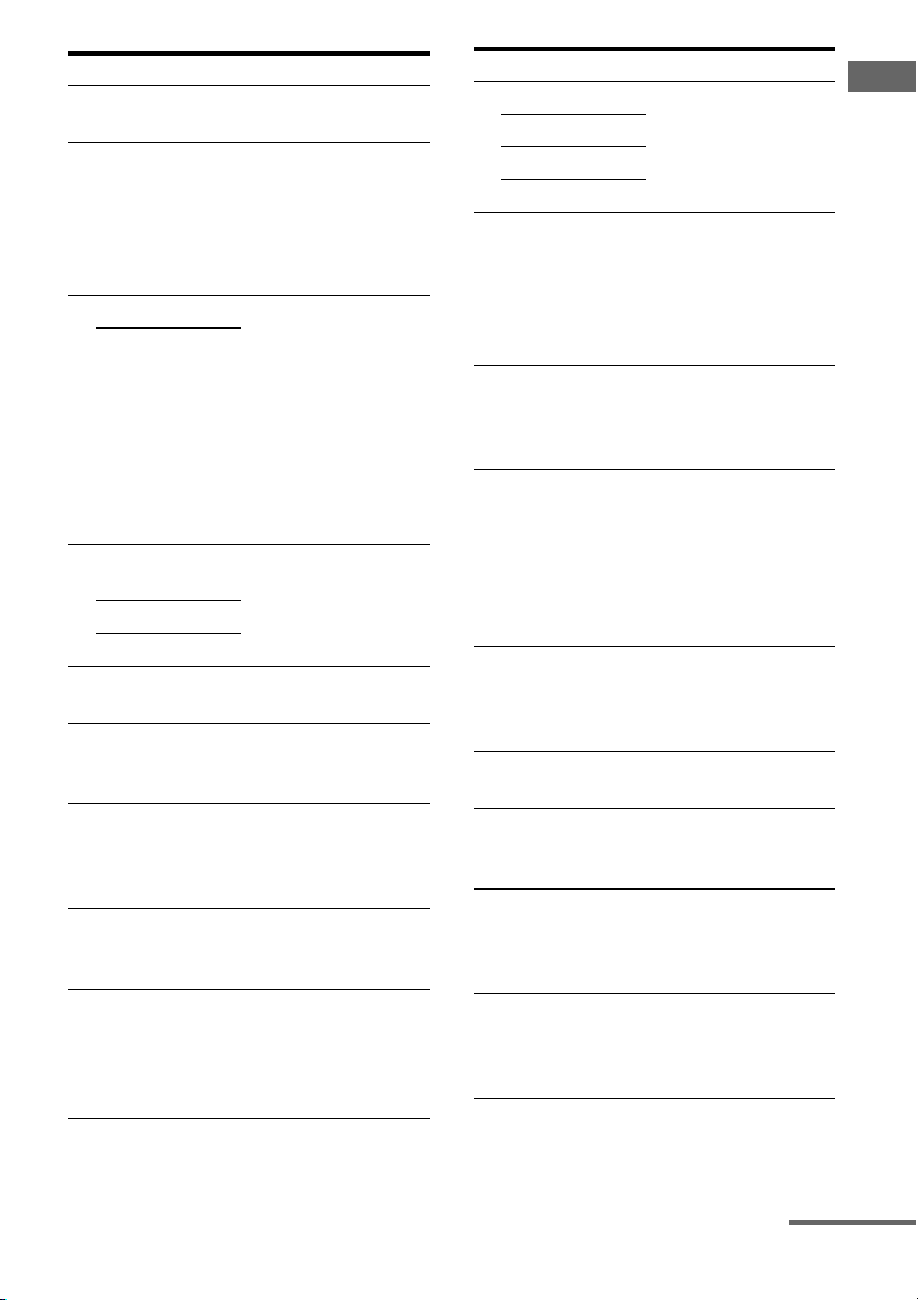
Table of Contents
Getting Started
Description and location of parts ..................6
1: Installing speakers ..................................15
2: Connecting speakers ...............................17
3: Connecting the monitor ..........................19
4a: Connecting the audio components ........21
4b: Connecting the video components .......26
5: Connecting the antennas (aerials) ...........35
6: Preparing the receiver and the remote ....36
7: Operating the receiver using the GUI
(Graphical User Interface) .....................38
8: Setting the speakers ................................41
9: Calibrating the appropriate speaker settings
automatically (Auto Calibration) ...........43
Playback
Selecting a component ................................50
Listening to a Super Audio CD/CD ............52
Watching a DVD/Blu-ray Disc ...................53
Enjoying video games ................................54
Watching video ...........................................55
Amplifier Operations
Settings for the audio
(Audio settings menu) ...........................56
Settings for the video
(Video settings menu) ............................57
Settings for HDMI (HDMI menu) ..............57
Settings for the system
(System settings menu) .........................58
Enjoying Surround Sound
Enjoying a pre-programmed sound field ....59
Adjusting the sound effect ..........................63
Using the surround back decoding mode ...65
Enjoying the surround effect at low volume
levels (NIGHT MODE) .........................67
Advanced Speakers Setting
Up
Adjusting the speaker settings manually .... 68
Adjusting the equalizer .............................. 74
Tuner Operations
Listening to FM/AM radio ......................... 76
Using the Radio Data System (RDS) ......... 79
Other Operations
Converting analog video input signals ....... 81
Using the DIGITAL MEDIA PORT
adapter ................................................... 81
Naming inputs ............................................ 85
Switching between digital and analog audio
(INPUT MODE) ................................... 86
Enjoying the sound/images from other
inputs ..................................................... 87
Changing the display ................................. 89
Using the sleep timer ................................. 93
Recording using the receiver ...................... 93
Using a bi-amplifier connection ................. 94
Operating without connecting to the
TV ......................................................... 95
Using the Remote
Operating each component using the
remote ................................................. 103
Programming the remote ......................... 105
Clearing all the contents of the remote’s
memory ............................................... 108
GB
4

Additional Information
Glossary ...................................................109
Precautions ...............................................111
Troubleshooting ....................................... 112
Specifications ........................................... 117
Index ......................................................... 120
GB
5
Getting Started
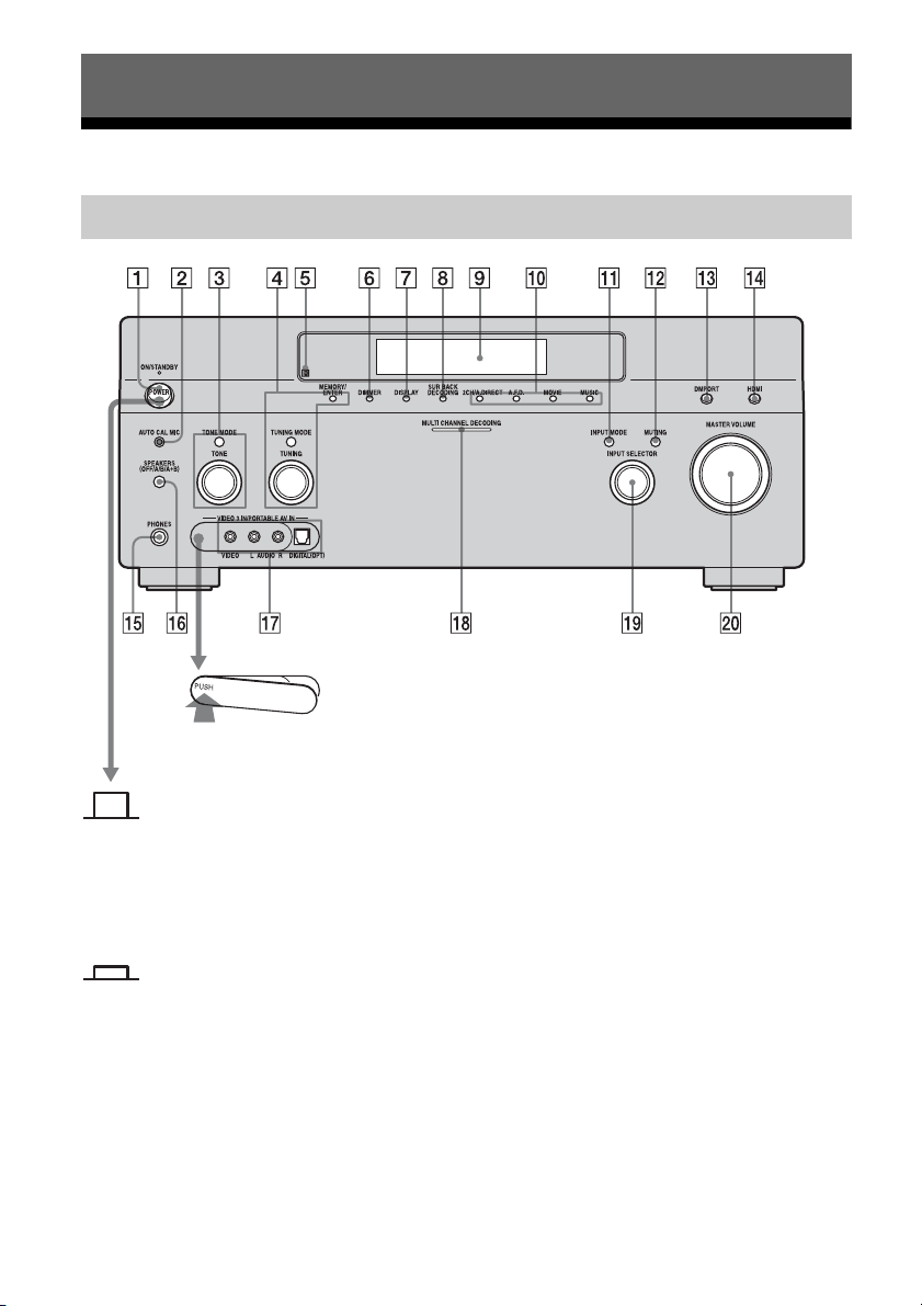
Description and location of parts
Front panel
To remove the cover
Press PUSH.
When you remove the cover, keep it out
of reach from children.
Status of the POWER button
Off
The receiver is turned off (initial
setting).
Press POWER to turn the receiver on.
You cannot turn the receiver on using
the remote.
On/Standby
Press ?/1 on the remote to turn the
receiver on or set it to the standby mode.
When you press POWER on the
receiver, the receiver will be turned off.
GB
6
Name Function
A POWER Press to turn the
receiver on or off.
B AUTO CAL MIC
jack
Connects to the
supplied optimizer
microphone for the
Digital Cinema Auto
Calibration function
(page 43).
C TONE MODE Adjusts FRONT/
TONE
CENTER/
SURROUND/
SURROUND BACK
BASS and TREBLE.
Press TONE MODE
repeatedly to select
BASS or TREBLE,
then turn TONE to
adjust the level.
D MEMORY/
ENTER
TUNING MODE
Press to operate a tuner
(FM/AM) (page 101-
102).
TUNING
E Remote sensor Receives signals from
remote commander.
F DIMMER Press repeatedly to
adjust brightness of the
display.
G DISPLAY Press repeatedly to
select information
displayed on the
display.
H SUR BACK
DECODING
Press to activate SB
DECODING
(page 65).
I Display
window
The current status of
the selected component
or a list of selectable
items appears here
(page 90).
Name Function
J 2CH/A.DIRECT Press to select sound
A.F.D.
field (page 59).
MOVIE
MUSIC
K INPUT MODE Press to select the input
mode when the same
components are
connected to both
digital and analog jacks
(page 86).
L MUTING Press to turn off the
sound temporarily.
Press the button again
to restore the sound.
M DMPORT Press to select the
audio/video input
signal from the
component connected
to the DIGITAL
MEDIA PORT adapter
(page 22, 81).
N HDMI Press to select input
source from the
component connected
to the HDMI IN jack.
O PHONES jack Connects to
headphones.
P SPEAKERS
(OFF/A/B/A+B)
Switch to OFF, A, B,
A+B of the front
speakers (page 42).
Q VIDEO 3 IN/
PORTABLE AV
IN jacks
Connect to a portable
audio/video c omponent
such as a camcorder or
video game.
R MULTI
CHANNEL
DECODING
Lights up when multichannel audio signals
are decoded.
lamp
Getting Started
continued
GB
7

Name Function
S INPUT
SELECTOR
T MASTER
VOLUME
Turn to select the input
source to play back.
Turn to adjust the
volume level of all
speakers at the same
time.
GB
8
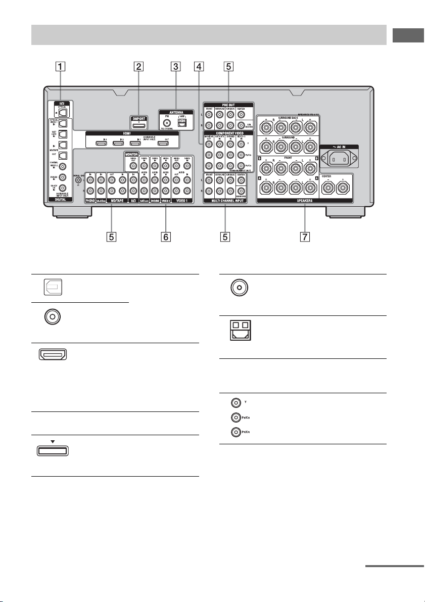
Rear panel
Getting Started
A DIGITAL INPUT/OUTPUT section
OPTICAL IN/
OUT jacks
COAXIAL IN
jacks
HDMI IN/
OUT* jacks
Connect to a DVD
player, Super Audio
CD player, etc. The
COAXIAL jack
provides a better
quality sound (page
19, 21, 22, 29, 30).
Connect to a DVD
player, Blu-ray Disc
Player, or a satellite
tuner. An image and
the sound are output
to TV or a projector
(page 19, 27).
B DMPORT
Connects to a Sony
DIGITAL MEDIA
PORT adapter
(page 22).
C ANTENNA section
FM ANTENNA
jack
AM
ANTENNA
jack
Connects to the FM
wire antenna (aerial)
supplied with this
receiver (page 35).
Connects to the AM
loop antenna (aerial)
supplied with this
receiver (page 35).
D COMPONENT VIDEO INPUT/
OUTPUT section
Y, PB/CB, PR/
IN/OUT*
C
R
jacks
Connect to a DVD
player, TV, or a
satellite tuner (page
19, 29, 30).
continued
GB
9
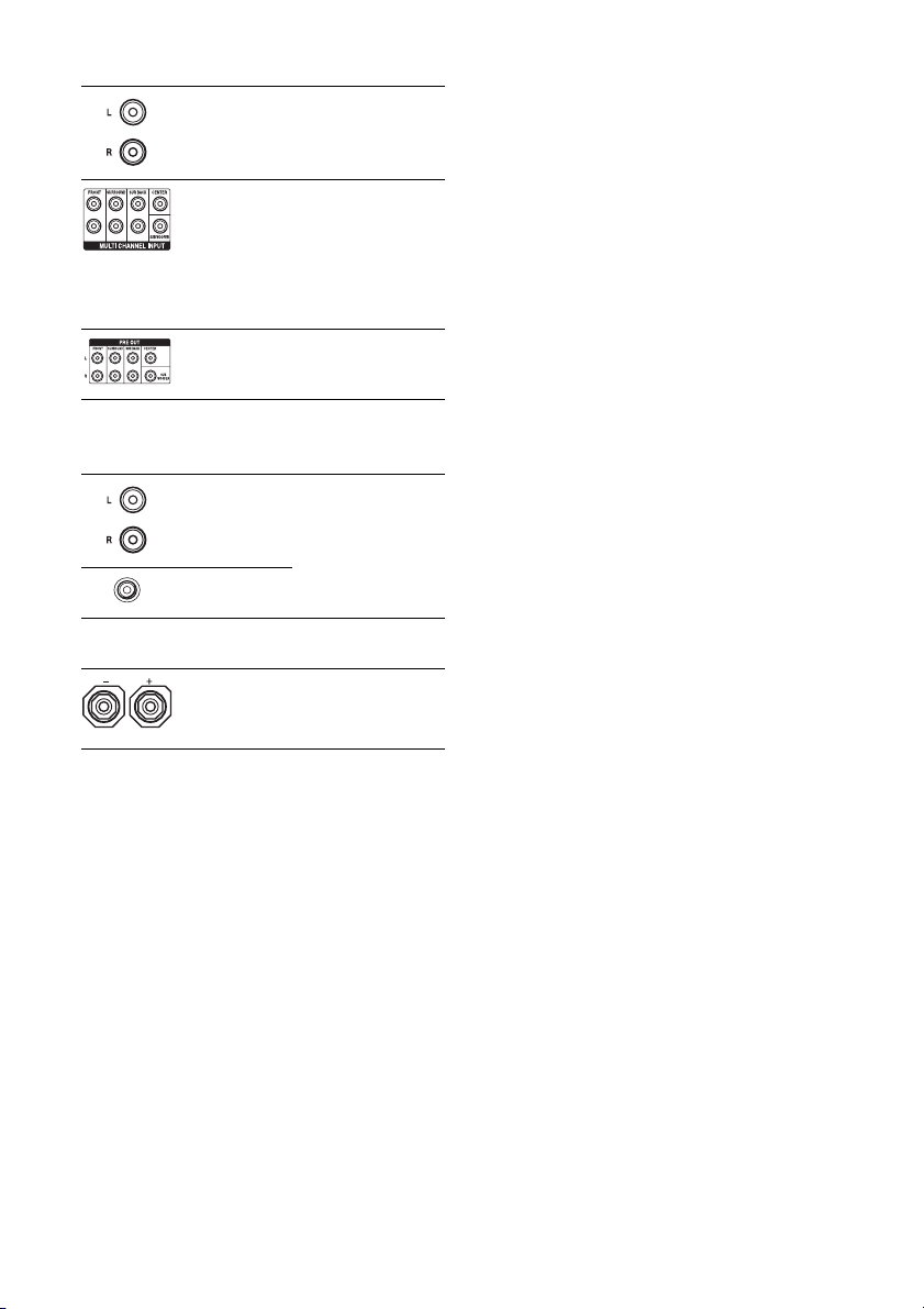
E AUDIO INPUT/OUTPUT section
AUD IO I N/
OUT jacks
Connect to a tape
deck or MD d eck, etc
(page 19, 21, 22, 25).
MULTI
CHANNEL
INPUT jacks
PRE OUT jacks Connect to an
Connect to a Super
Audio CD player or
DVD player with an
analog audio jack for
7.1 channel or 5.1
channel sound (page
21, 24).
external power
amplifier.
F VIDEO/AUDIO INPUT/OUTPUT
section
AUD IO I N/
OUT jacks
VIDEO IN/
OUT* jacks
Connect to a VCR or
a DVD player etc.
(page 19, 29, 30, 31).
G SPEAKERS section
Connects to speakers
(page 17).
* You can watch the selected input image when you
connect the MONITOR VIDEO OUT jack to a TV
(page 19). You can operate this receiver using a
GUI (Graphical User Interface) (page 38).
10
GB
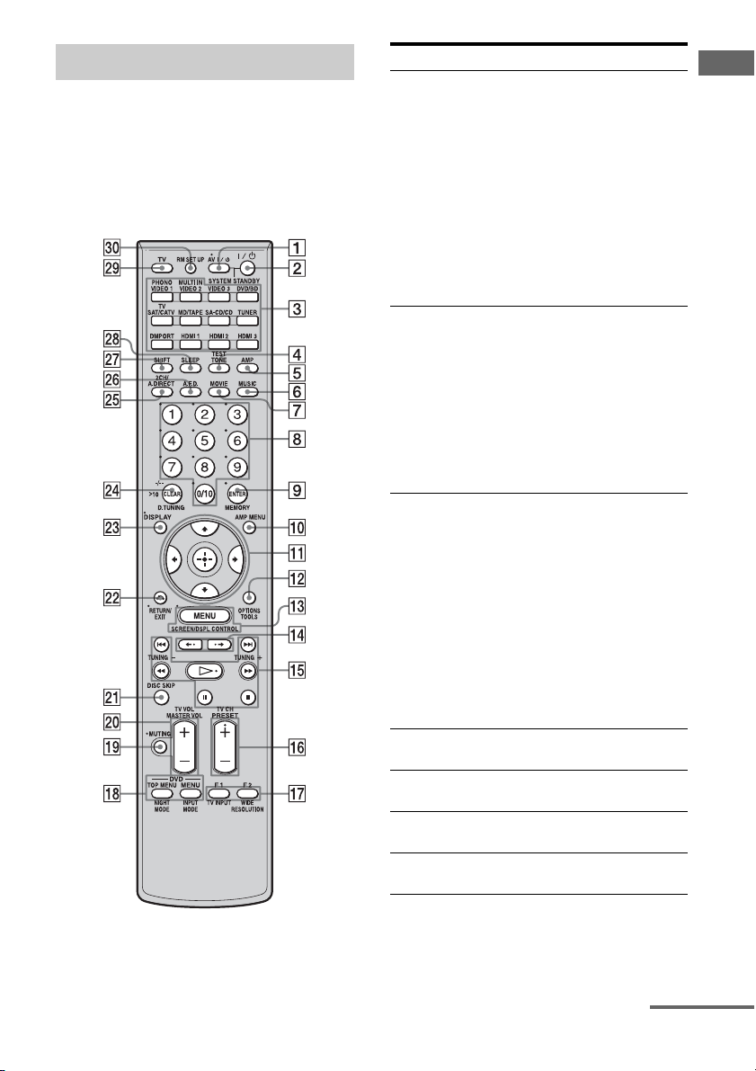
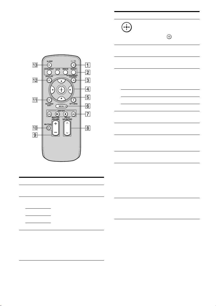
Remote commander
You can use the supplied remote RM-AAP019
to operate the receiver and to control the Sony
audio/video components that the remote is
assigned to operate (page 105).
RM-AAP019
Name Function
A AV ?/1 (on/
standby)
B ?/1 (on/
standby)
Press to turn on or off the audio/
video components that the
remote is assigned to operate
(page 105).
If you press the ?/1 (B) at the
same time, it will turn off the
receiver and other Sony
components (SYSTEM
STANDBY).
Note
The function of the AV ?/1
switch changes automatically
each time you press the input
button (C).
Press to turn the receiver on or
off.
To turn off all components,
press ?/1 and AV ?/1 (A) at
the same time (SYSTEM
STANDBY).
Saving the power in
standby mode.
When “HDMI Control” is set to
“OFF” (page 57).
C Input
buttons
D TEST TONE Press to output the test tone
E AMP Press to enable the receiver
F MUSIC Press to select sound field
G MOVIE Press to select sound field
Press one of the buttons to
select the component you want
to use. Press a pink-labeled
button after pressing SHIFT
(wj). When you press any of the
input buttons, the receiver turns
on. The buttons are factory
assigned to control Sony
components (page 50). You can
program the remote to control
non-Sony components
following the steps in
“Programming the remote”
(page 105).
from each speaker.
operation (page 38).
(page 62).
(page 62).
Getting Started
continued
11
GB
Name Function
H Numeric
buttons
I ENTER Press to enter the value after
MEMORY Press to store a station during
J AMP MENU Press to display the menu to
K
V/v/B/b
L OPTIONS Press to display and select items
TOOLS Press to display and select items
M MENU Press to display the menu to
SCREEN/
DSPL
CONTROL
N B·/·b Press to select the album.
O m/M
a)
x
a)
X
a) b)
H
./>
TUNING +/– Press to select station
Press to
– preset/tune to preset stations.
– select track numbers of the
CD player, DVD player, Bluray Disc Player or MD deck.
Press 0/10 to select track
number 10.
– select channel numbers of
the VCR or satellite tuner.
– After pressing TV (wl),
press the numeric buttons to
select the TV channels.
selecting a channel, disc or
track using the numeric buttons.
tuner operation.
operate the receiver.
Press V/v/B/b to select the
menu items. Then press to
enter the selection.
from option menus for receiver
and DVD player, Blu-ray Disc
Player.
from the option menus for DVD
player or Blu-ray Disc Player,
etc.
operate the audio/video
components.
Press SHIFT (wj), then press
MENU to switch the display
mode of the menu between
SCREEN (to display the menu
on the TV screen) and DSPL (to
display the menu in the display
window).
a)
Press to operate the DVD
player, Blu-ray Disc Player, CD
player, MD deck, tape deck, or
component connected to the
a)
DIGITAL MEDIA PORT
adapter etc.
(page 102).
Name Function
P PRESET
b)
/–
+
TV CH +/– Press TV (wl), then press TV
Q F1/F2 Press TV (wl), then press F1 or
TV/INPUT Press TV/INPUT and TV (wl)
WIDE Press repeatedly to select the
RESOLUTION
R DVD/
TOP MENU,
MENU
NIGHT
MODE
INPUT
MODE
S MUTING Press to turn off the sound
Press to register FM/AM or to
select preset stations.
CH +/– to operate the TV,
satellite tuner, VCR, etc.
F2 to select a component to
operate.
• HDD recorder
F1: HDD
F2: DVD player, Blu-ray Disc
Player
• DVD/VHS combo player
F1: DVD player, Blu-ray Disc
Player
F2: VHS
at the same time to select the
input signal (TV input or video
input).
wide picture mode.
Press SHIFT (wj) then press
RESOLUTION repeatedly to
change the resolution of signals
output from the HDMI OUT or
COMPONENT VIDEO
MONITOR OUT jack
(page 81).
Press to display the menus of
the DVD player on the TV
screen. Then use V /v/B/b and
to perform a menu
operations (page 104).
Press AMP (5), then press
NIGHT MODE to activate the
NIGHT MODE function
(page 67).
Press AMP (5), then press
INPUT MODE to select the
input mode when the same
components are connected to
both digital and analog jacks
(page 86).
temporarily. Press the button
again to restore the sound.
12
GB
Name Function
T MASTER
VOL +
TV VOL +/– Press TV (wl), then press TV
U DISC SKIP Press to skip a disc when using
V RETURN/
EXIT O
W DISPLAY Press to select information
X CLEAR Press to
>10 Press to select
D.TUNING Press to enter direct tuning
Y 2CH/
A.DIRECT
Z A.F.D. Press to select sound field
wj SHIFT Press to light up the button. It
Press to adjust the volume level
/–
of all speakers at the same time.
VOL +/– to adjust the volume
level of the TV.
a multi-disc changer.
Press to return to the previous
menu or exit the menu while the
menu or on-screen guide of the
VCR, DVD player, or satellite
tuner is displayed on the TV
screen.
displayed in the display
window, TV screen of the VCR,
satellite tuner, CD player, DVD
player, Blu-ray Disc Player, or
MD deck.
Note
In the SCREEN mode, press the
button to display the menu on
the TV screen.
– clear a mistake when you
press the incorrect numeric
button.
– return to continuous
playback, etc. of the satellite
tuner or DVD player.
– track numbers over 10 of the
VCR, satellite tuner, CD
player or MD deck.
– channel numbers of the
Digital CATV terminal.
mode (page 77).
Press to select sound field
(page 59) or to switch the audio
of the selected input to analog
signal without any adjustment
(page 101).
(page 60).
changes the remote button
function to activate the buttons
with pink printing.
Name Function
wk SLEEP Press to activate the sleep timer
wl TV Press to enable the TV
e; RM SET UP Press to set up the remote.
a)
See the table on page 104 for information on the
buttons that you can use to control each
component.
b)
The tactile dot is attached to these buttons (H,
PRESET+). Use as a mark of operation.
function and the duration which
the receiver turns off
automatically (page 93).
operation.
Notes
• Some functions explained in this section may not
work depending on the model.
• The above explanation is intended to serve as an
example only. Therefore, depending on the
component, the above operation may not be
possible or may operate differently than described.
Getting Started
continued
13
GB
RM-AAU018
This remote can only be used to operate the
receiver. You can control the main functions of
the receiver with simple operations using this
remote.
Name Function
A ?/1 (on/
standby)
B 2CH/
A.DIRECT
A.F.D.
MOVIE
MUSIC
C SCREEN/
DSPL
CONTROL
Press to turn a receiver on or off.
Press to select sound field
(page 59).
Press to switch the display
mode of the menu between
SCREEN (to display the menu
on the TV screen) and DSPL (to
display the menu in the display
window).
Name Function
D
V/v/B/b
E OPTIONS Press to display and select items
F MENU Press to display the menu to
G DMPORT Press to operate component
N Starts play.
x Stops play.
./> Skips tracks.
H INPUT
SELECTOR
I MASTER
VOLUME +/–
J MUTING Press to turn off the sound
K RETURN/
EXIT
L DISPLAY Press to select information
M SLEEP Press to activate the sleep timer
After pressing SCREEN/DSPL
CONTROL (3), press V/v/B/
b to select the menu items.
Then press to enter the
selection.
from option menus.
operate the receiver.
connected to the DIGITAL
MEDIA PORT adapter
(page 50).
Press to select the input source
to play back.
Press to adjust the volume level.
temporarily. Press the button
again to restore the sound.
Press to return to the previous
menu or exit the menu.
displayed in the display
window.
Note
In the SCREEN mode, press the
button to display the menu on
the TV screen.
function and the duration which
the receiver turns off
automatically (page 93).
14
GB

1: Installing speakers
This receiver allows you to use a 7.1 channel
system (7 speakers and one sub woofer).
Enjoying a 5.1/7.1 channel
system
To fully enjoy theater-like multi-channel
surround sound requires five speakers (two
front speakers, a center speaker, and two
surround speakers) and a sub woofer (5.1
channel system).
Example of a 5.1 channel
speaker system configuration
Getting Started
You can enjoy high fidelity reproduction of
DVD software recorded sound in the Surround
EX format if you connect one additional
surround back speaker (6.1 channel system) or
two surround back speakers (7.1 channel
system.) See “Using the surround back
decoding mode” (page 65).
Example of a 7.1 channel
speaker system configuration
AFront left speaker
BFront right speaker
CCenter speaker
DSurround left speaker
ESurround right speaker
HSub woofer
AFront left speaker
BFront right speaker
CCenter speaker
DSurround left speaker
ESurround right speaker
FSurround back left speaker
GSurround back right speaker
HSub woofer
continued
15
GB
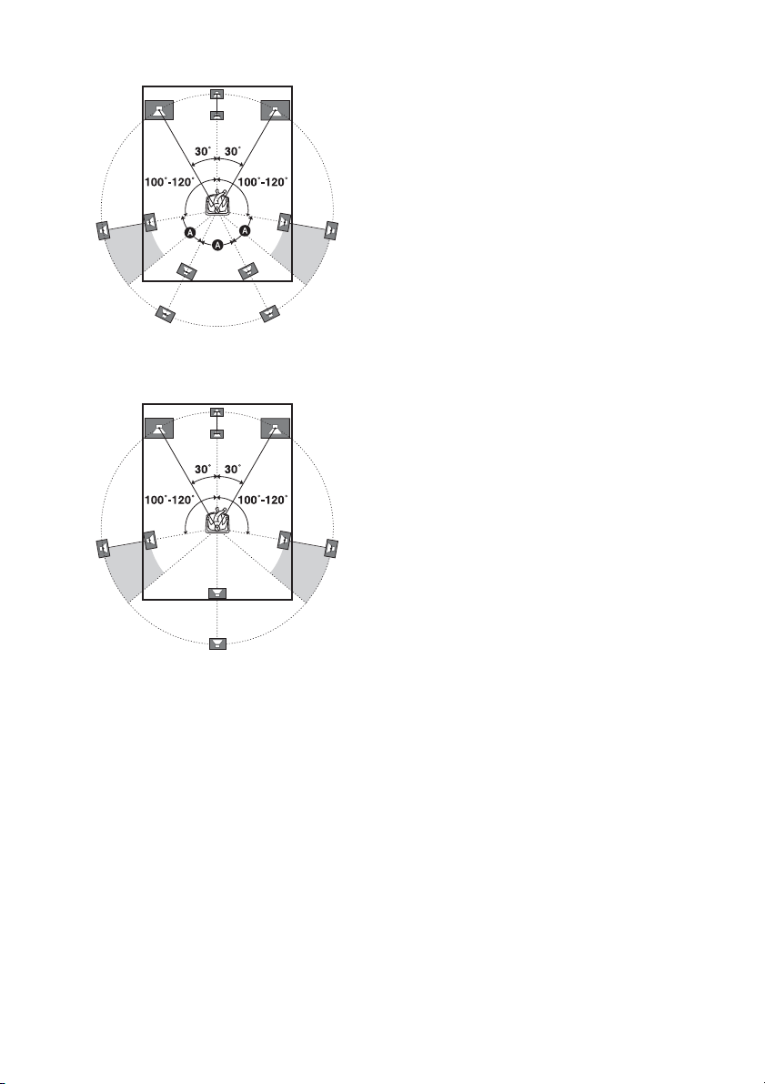
Tips
•The angle A should be the same.
• When you connect a 6.1 channel speaker system,
place the surround back speaker behind the seating
position.
• Since the sub woofer does not emit highly
directional signals, you can place it wherever you
want.
GB
16
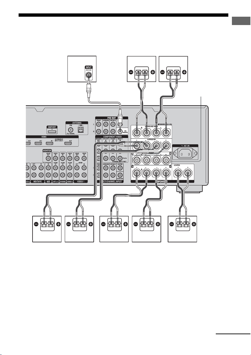
2: Connecting speakers
Before connecting cords, make sure to
disconnect the AC power cord (mains lead).
HGF
Getting Started
AB
A Monaural audio cord (not supplied)
B Speaker cords (not supplied)
BADEC
FRONT SPEAKERS
B terminals
a)
ACenter speaker
BFront speaker A (L)
CFront speaker A (R)
DSurround speaker (L)
ESurround speaker (R)
FSurround back speaker (L)
GSurround back speaker (R)
HSub woofer
c)
a)
If you have an additional front speaker
system, connect them to the FRONT
SPEAKERS B terminals. You can select
the front speaker system you want to use
b)
b)
with the SPEAKERS switch (OFF/A/B/
A+B) on the front panel (page 42).
continued
17
GB

b)
If you connect only one surround back
speaker, connect it to the SURROUND
BACK SPEAKERS L terminals.
c)
When you connect a sub woofer with an auto
standby function, turn off the function when
watching movies. If the auto standby
function is set to on, it turns to standby mode
automatically based on the level of the input
signal to a sub woofer, then sound may not
be output.
Notes
• When you connect all the speakers with a nominal
impedance of 8 ohms or higher, set “Impedance” in
the Speaker settings menu to “8 Ω.” In other
connections, set it to “4 Ω.” For details, see “8:
Setting the speakers” (page 41).
• Before connecting the AC power cord (mains
lead), make sure that metallic wires of the speaker
cords are not touching each other between the
SPEAKERS terminals.
Tip
To connect certain speakers to another power
amplifier, use the PRE OUT jacks. The same signal
is output from both the SPEAKERS terminals and
the PRE OUT jacks. For example, if you want to
connect just the front speakers to another amplifier,
connect that amplifier to the PRE OUT FRONT L
and R jacks.
18
GB
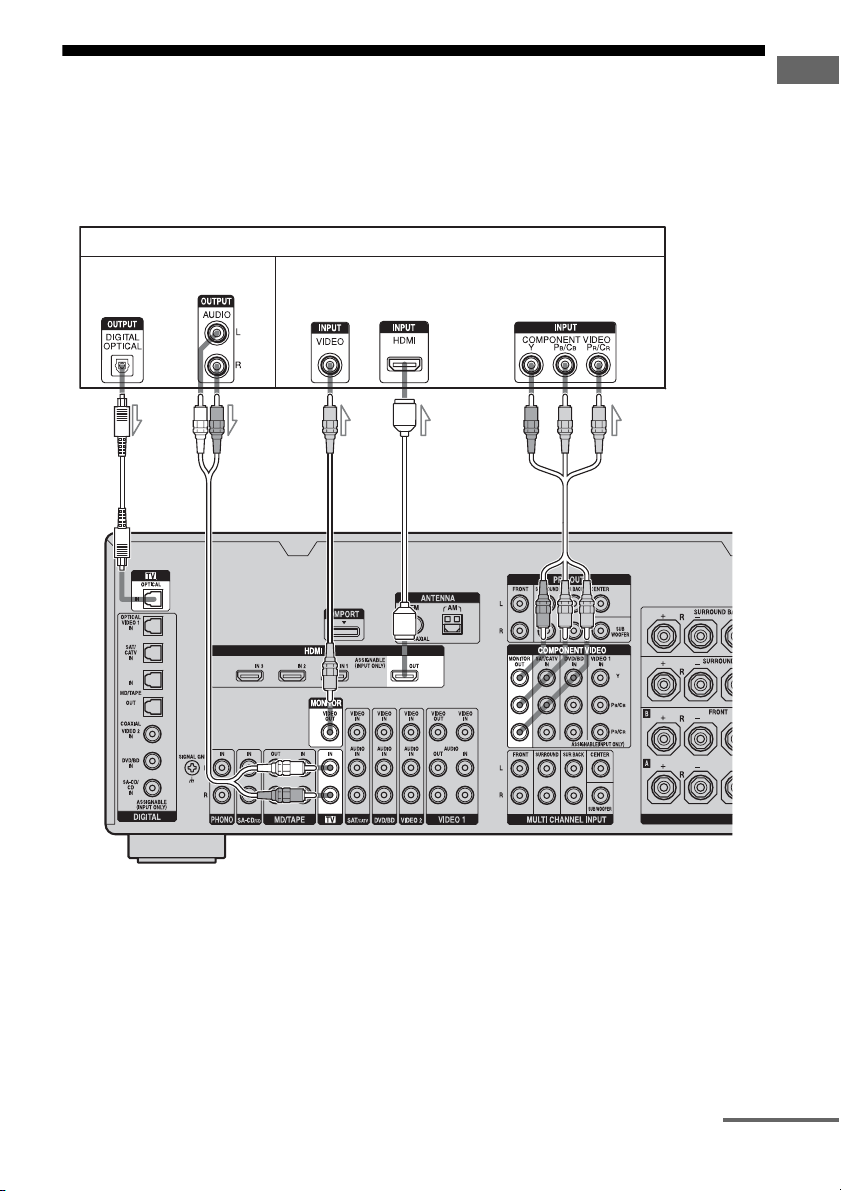
3: Connecting the monitor
You can watch the selected input image when
you connect the MONITOR VIDEO OUT jack
to a TV. You can operate this receiver using a
GUI (Graphical User Interface).
TV monitor
Audio signals
Video signals
Getting Started
It is not necessary to connect all the cables.
Connect audio and video cords according to
the jacks of your components.
AB
CD E
A Optical digital cord (not supplied)
B Audio cord (not supplied)
C Video cord (not supplied)
D HDMI cable (not supplied)
E Component video cord (not supplied)
continued
19
GB

Notes
• Before connecting cords, make sure to disconnect
the AC power cord (mains lead).
• Connect image display components such as a TV
monitor or a projector to the MONITOR VIDEO
OUT jack on the receiver. You may not be able to
record, even if you connect recording components.
• Turn on the receiver when the video and audio of a
playback component are being output to a TV via
the receiver. If the power supply of the receiver is
not turned on, neither video nor audio is
transmitted.
• Depending on the status of the connection between
the TV and the antenna (aerial), the image on the
TV screen may be distorted. In this case, place the
antenna (aerial) farther away from the receiver.
Tips
• The receiver has a video conversion function. For
details, see “Notes on converting video signals”
(page 33).
• The sound of the TV is output from the speakers
connected to the receiver if you connect the sound
output jack of the TV and the TV IN jacks of the
receiver. In this configuration, set the sound output
jack of the TV to “Fixed” if it can be switched
between either “Fixed” or “Variable.”
• The screen saver is activated when the GUI menu
is displayed on the TV screen and there has been no
operation attempted for 15 minutes.
20
GB
4a: Connecting the audio components
Getting Started
How to hook up your
components
This section describes how to hook up your
components to this receiver. Before you begin,
refer to “Component to be connected” below
for the pages which describe how to connect
each component.
After hooking up all your components,
proceed to “5: Connecting the antennas
(aerials)” (page 35).
Component to be connected Page
Super Audio CD
player/ CD player
MD player With digital audio
Tape deck, Analog disc turntable 25
With digital audio
output
With multi-channel
audio output
With analog audio
output only
output
With analog audio
output only
22
24
25
22
25
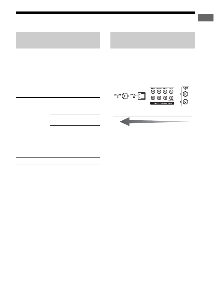
Audio input/output jacks to be
connected
The sound quality depends on the jack used.
Refer to the illustration that follows. Select the
connection configuration according to the
jacks of your components.
Digital Analog
High quality sound
Notes
• When connecting optical digital cords, insert the
plugs straight in until they click into place.
• Do not bend or tie optical digital cords.
Tip
All the digital audio jacks are compatible with 32
kHz, 44.1 kHz, 48 kHz, and 96 kHz sampling
frequencies.
21
GB
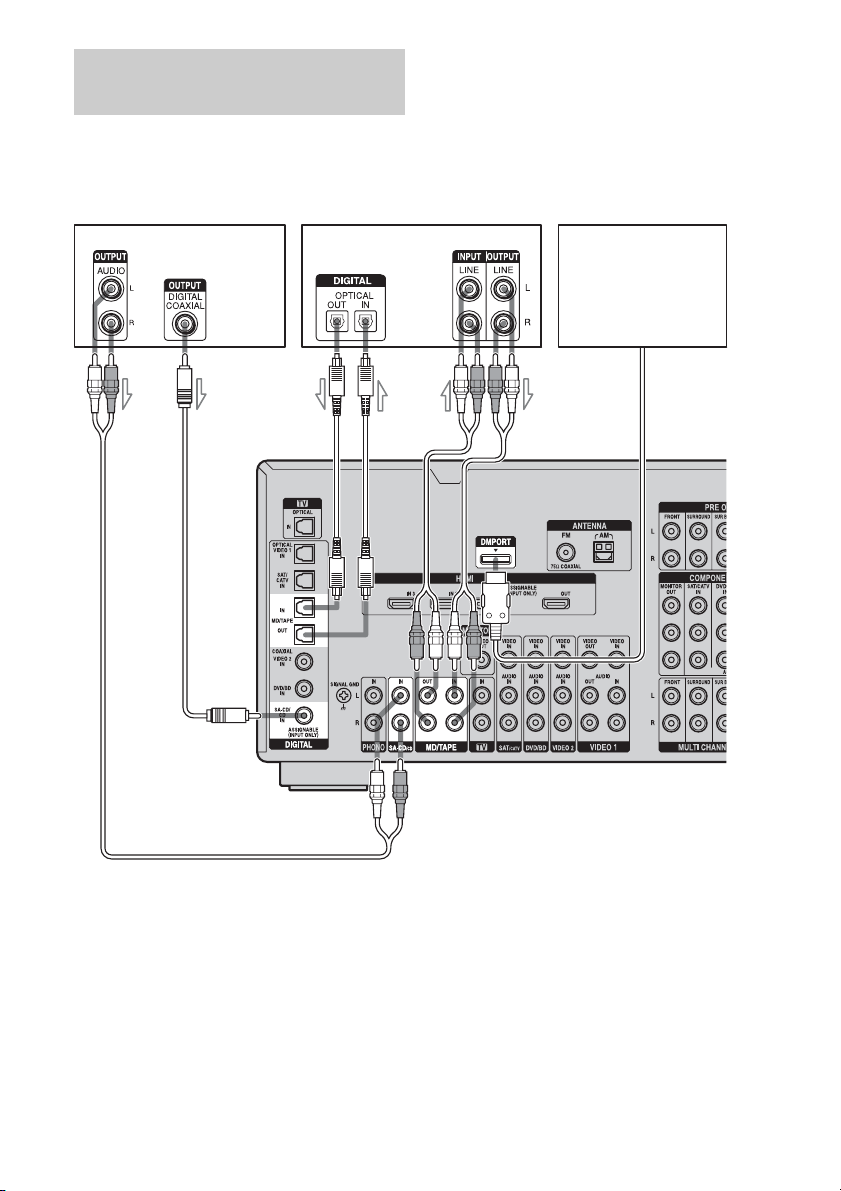
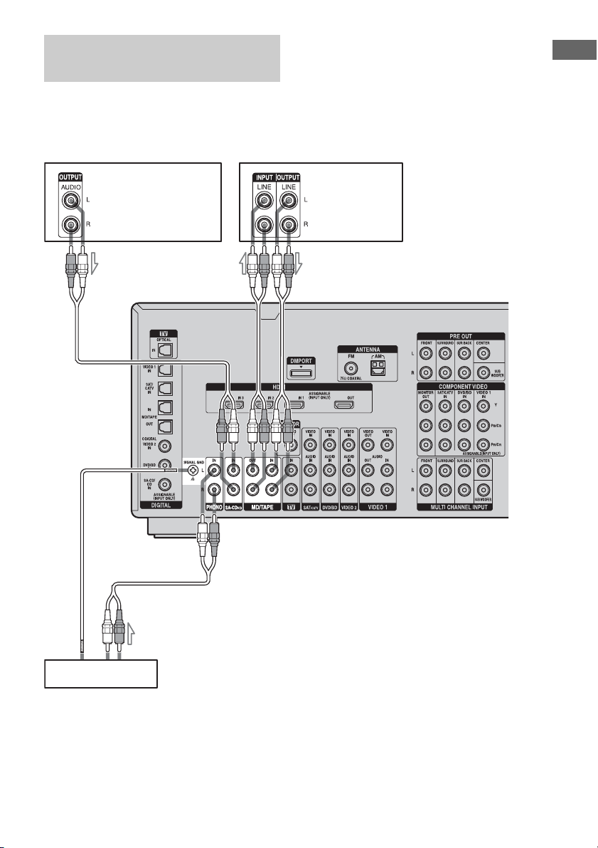
Connecting components with
digital audio input/output jacks
The following illustration shows how to
connect a Super Audio CD player, CD player,
an MD deck and DIGITAL MEDIA PORT
adapter.
Super Audio CD
player, CD player
MD deck
C
DIGITAL MEDIA PORT
ABA
adapter
A Audio cord (not supplied)
B Coaxial digital cord (not supplied)
C Optical digital cord (not supplied)
Notes
• Before connecting cords, make sure to disconnect
the AC power cord (mains lead).
GB
22
• To disconnect the DIGITAL MEDIA PORT
adapter, remove the cable by squeezing the sides of
the connector, since the connector is locked in
place.

Notes on playing a Super Audio
CD on a Super Audio CD player
• No sound is output when playing a Super
Audio CD on a Super Audio CD player
connected to only the COAXIAL SA-CD/
CD IN jack on this receiver. When you play
a Super Audio CD, connect the player to the
MULTI CHANNEL INPUT or SA-CD/CD
IN jacks. Refer to the operating instructions
supplied with the Super Audio CD player.
• You cannot make digital recordings of a
Super Audio CD.
• When connecting optical digital cords, insert
the plugs straight in until they click into
place.
• Do not bend or tie optical digital cords.
If you want to connect several
digital components, but cannot
find an unused input
See “Enjoying the sound/images from other
inputs” (page 87).
Getting Started
23
GB
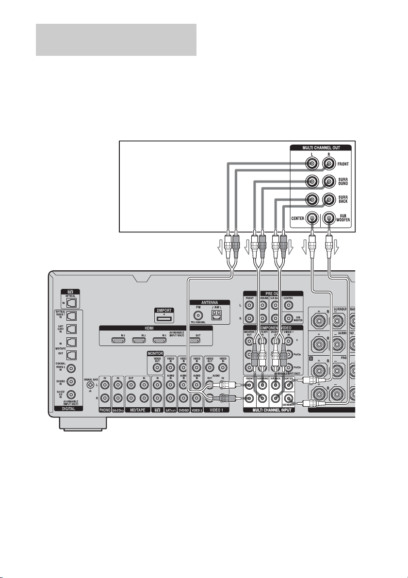
Connecting components with
multi-channel output jacks
If your DVD or Super Audio CD player is
equipped with multi-channel output jacks, you
can connect them to the MULTI CHANNEL
INPUT jacks of this receiver to enjoy multichannel sound. Alternatively, the multichannel input jacks can be used to connect an
external multi-channel decoder.
DVD player,
Super Audio CD player, etc.
AB
A Audio cord (not supplied)
B Monaural audio cord (not supplied)
Notes
• Before connecting cords, make sure to disconnect
the AC power cord (mains lead).
• DVD and Super Audio CD players do not have the
SURROUND BACK jacks.
GB
24
• When “Sur Back Assign” is set to “BI-AMP” in the
Speaker settings menu, the input to the SUR BACK
jacks is invalid.
• Audio input signals from MULTI CHANNEL
INPUT jacks are not output to any audio output
jacks. The signals cannot be recorded.
Connecting components with
analog audio jacks
The following illustration shows how to
connect a component with analog jacks, such
as tape deck, turntable, etc.
Getting Started
A
A
Super Audio
CD player,
CD player
MD deck,
Tape deck
A
Tu rn t ab l e
A Audio cord (not supplied)
Notes
• If your turntable has a ground (earth) wire, connect
it to the (U) SIGNAL GND terminal.
• Before connecting cords, make sure to disconnect
the AC power cord (mains lead).
25
GB
4b: Connecting the video components
How to hook up your
components
This section describes how to hook up your
components to this receiver. Before you begin,
refer to “Component to be connected” below
for the pages which describe how to connect
each component.
After hooking up all your components,
proceed to “5: Connecting the antennas
(aerials)” (page 35).
Component to be connected Page
TV monitor 19
With HDMI jack 27
DVD player, Blu-ray Disc Player 29
Satellite tuner, CATV system 30
DVD recorder, VCR 31
Camcorder, video game, etc. 31
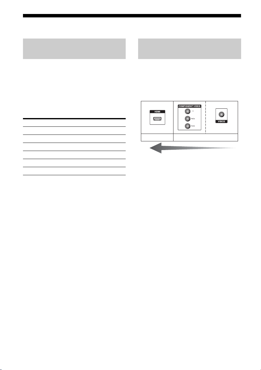
Video input/output jacks to be
connected
The image quality depends on the connecting
jack. Refer to the illustration that follows.
Select the connection according to the jacks on
your components.
Digital Analog
High quality image
26
GB
Connecting components with
HDMI jacks
HDMI is the abbreviated name for HighDefinition Multimedia Interface. It is an
interface which transmits video and audio
signals in digital format.
HDMI features
• A digital audio signals transmitted by HDMI
can be output from the speakers and the PRE
OUT jacks on this receiver. This signal
supports Dolby Digital, DTS, and linear
PCM.
• Linear PCM (sampling frequency less than
192 kHz) with digital audio signals of up to
8 channels can be received with this receiver
using the HDMI jack.
• Analog video signals input to the VIDEO
jack, or COMPONENT VIDEO jacks can be
output as HDMI signals. Audio signals are
not output from an HDMI OUT jack when
the image is converted.
• This receiver supports xvYCC transmission.
• This receiver supports the HDMI
CONTROL function. Refer to “HDMI
CONTROL Guide” supplied with the
receiver.
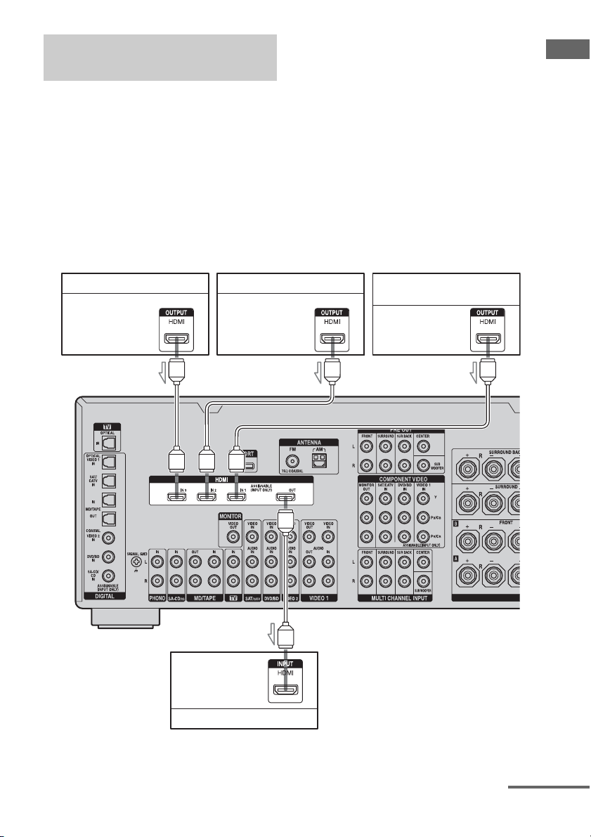
Getting Started
DVD player Satellite tuner Blu-ray Disc Player, PS3™,
Audio/video
signals
Audio/video
signals
hard disk recorder
Audio/video
signals
AAA
A
Audio/video
signals
TV monitor, projector, etc.
A HDMI cable (not supplied)
continued
27
GB

Notes on connecting cables
• We recommend that you use a Sony HDMI
cable.
• We recommend that you use an HDMI,
version 1.3a, category 2 cable with the
HDMI logo (made by Sony) to watch a video
image of 1080p or higher.
• We do not recommend using an HDMI-DVI
conversion cable. When you connect an
HDMI-DVI conversion cable to a DVI-D
component, the sound and/or the image may
not be output. Connect other audio cords or
digital connecting cords, then set “Input
Assign” in the Input Option menu when the
sound is not output correctly.
• Before connecting cables, make sure to
disconnect the AC power cord (mains lead).
Notes on HDMI connections
• Check the setup of the connected component
if an image is poor or the sound does not
come out of a component connected via the
HDMI cable.
• An audio signal input to the HDMI IN jack
is output from the speaker output jacks,
HDMI OUT jack and PRE OUT jacks. It is
not output from any other audio jacks.
• A video signal input to the HDMI IN jack
can only be output from the HDMI OUT
jack. The video input cannot be output from
the VIDEO OUT jacks, or MONITOR
VIDEO OUT jacks.
• The audio and video signals of HDMI input
are not output from the HDMI OUT jack
while the receiver menu is displayed.
• When you want to listen to the sound from
the TV speaker, set “HDMI Audio” to
“TV+AMP” in the HDMI settings menu. If
set to “AMP,” the sound is not output from
the TV speaker.
• DSD signals of Super Audio CD are not
input and output.
• Be sure to turn on the receiver when video
and audio signals of a playback component
are being output to a TV through this
receiver. Unless the power is on, neither
video nor audio signals will be transmitted.
• Audio signals (sampling frequency, bit
length, etc.) transmitted from an HDMI jack
may be suppressed by the connected
component. Check the setup of the
connected component if an image is poor or
the sound does not come out of a component
connected via the HDMI cable.
• Sound may be interrupted when the
sampling frequency or the number of
channels of audio output signals from the
playback component is switched.
• When the connected component is not
compatible with copyright protection
technology (HDCP), the image and/or the
sound from the HDMI OUT jack may be
distorted or may not be output.
In this case, check the specification of the
connected component.
• Refer to the operating instructions of each
component connected for details.
28
GB
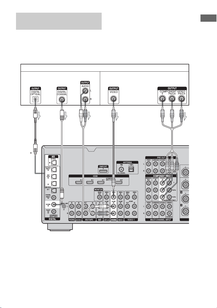
Connecting a DVD player, Bluray Disc Player
The following illustration shows how to
connect a DVD player, Blu-ray Disc Player.
It is not necessary to connect all the cables.
Connect audio and video cords according to
the jacks of your components.
DVD player, Blu-ray Disc Player
Audio signals Video signals
Notes
• To output multi-channel digital audio, set the
digital audio output setting on the DVD player,
Blu-ray Disc Player. Refer to the operating
instructions supplied with the DVD player, Blu-ray
Disc Player.
• Before connecting cords, make sure to disconnect
the AC power cord (mains lead).
Getting Started
ABC
A Optical digital cord (not supplied)
B Coaxial digital cord (not supplied)
C Audio cord (not supplied)
* When you connect a component equipped with an
OPTICAL jack, set “Input Assign” in the Input
menu.
D
E
D Video cord (not supplied)
E Component video cord (not supplied)
29
GB
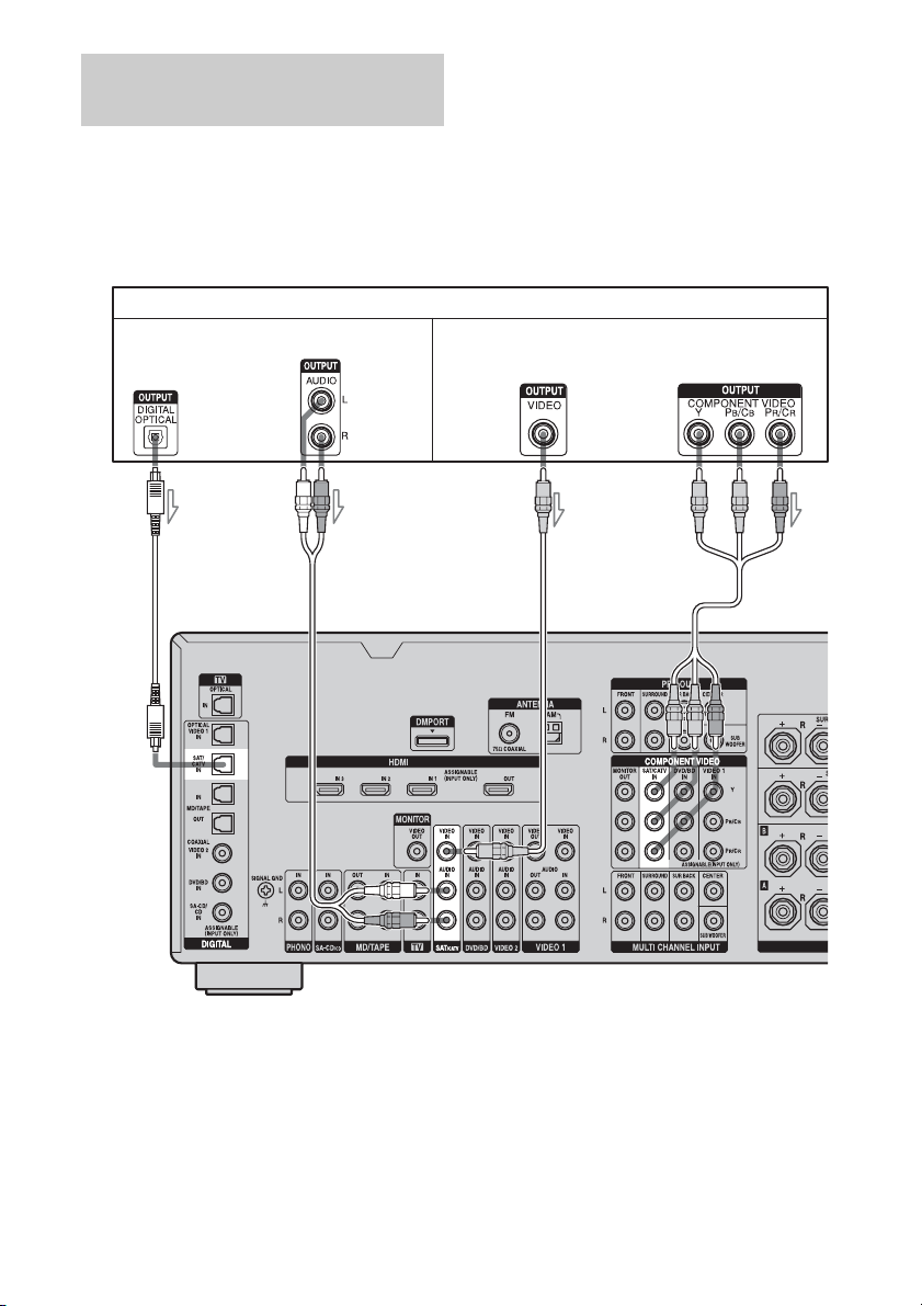
Connecting a satellite tuner,
CATV system
The following illustration shows how to
connect a satellite tuner, CATV system.
It is not necessary to connect all the cables.
Connect audio and video cords according to
the jacks of your components.
Satellite tuner, CATV system
Audio signals Video signals
AB C D
A Optical digital cord (not supplied)
B Audio cord (not supplied)
C Video cord (not supplied)
D Component video cord (not supplied)
Note
Before connecting cords, make sure to disconnect
the AC power cord (mains lead).
GB
30
 Loading...