


4-241-669-11(2)
FM Stereo
FM-AM Receiver
Operating Instructions
Owner’s Record
The model and serial numbers are located on the rear of the unit. Record the serial
number in the space provided below. Refer to them whenever you call upon your Sony
dealer regarding this product.
Model No. Serial No.
STR-DA2ES
© 2002 Sony Corporation
WARNING
To prevent fire or shock hazard, do not
expose the unit to rain or moisture.
To prevent fire, do not cover the ventilation of the
apparatus with news papers, table-cloths, curtains,
etc. And don’t place lighted candles on the apparatus.
To prevent fire or shock hazard, do not place objects
filled with liquids, such as vases, on the apparatus.
Don’t throw away the battery with
general house waste, dispose of it
correctly as chemical waste.
Do not install the appliance in a confined space, such
as a bookcase or built-in cabinet.
For customers in the United States
This symbol is intended to alert the
user to the presence of uninsulated
“dangerous voltage” within the
product’s enclosure that may be of
sufficient magnitude to constitute a
risk of electric shock to persons.
This symbol is intended to alert the
user to the presence of important
operating and maintenance (servicing)
instructions in the literature
accompanying the appliance.
WARNING
This equipment has been tested and found to comply
with the limits for a Class B digital device, pursuant
to Part 15 of the FCC Rules. These limits are
designed to provide reasonable protection against
harmful interference in a residential installation. This
equipment generates, uses, and can radiate radio
frequency energy and, if not installed and used in
accordance with the instructions, may cause harmful
interference to radio communications. However, there
is no guarantee that interference will not occur in a
particular installation. If this equipment does cause
harmful interference to radio or television reception,
which can be determined by turning the equipment
off and on, the user is encouraged to try to correct the
interference by one or more of the following
measures:
– Reorient or relocate the receiving antenna.
– Increase the separation between the equipment and
receiver.
– Connect the equipment into an outlet on a circuit
different from that to which the receiver is
connected.
– Consult the dealer or an experienced radio/TV
technician for help.
CAUTION
You are cautioned that any changes or modification
not expressly approved in this manual could void
your authority to operate this equipment.
Note to CATV system installer:
This reminder is provided to call CATV system
installer’s attention to Article 820-40 of the NEC that
provides guidelines for proper grounding and, in
particular, specifies that the cable ground shall be
connected to the grounding system of the building, as
close to the point of cable entry as practical.
ENERGY STAR
mark.
As an ENERGY STAR® partner, Sony
Corporation has determined that this
product meets the ENERGY STAR
guidelines for energy efficiency.
®
is a U.S. registered
®
GB
2
4-XXX-XXX-XX AA
P
For customers in Canada
CAUTION
TO PREVENT ELECTRIC SHOCK, DO NOT USE
THIS POLARIZED AC PLUG WITH AN
EXTENSION CORD, RECEPTACLE OR OTHER
OUTLET UNLESS THE BLADES CAN BE FULLY
INSERTED TO PREVENT BLADE EXPOSURE.
About This Manual
• The instructions in this manual are for model
STR-DA2ES. Check your model number by
looking at the lower right corner of the front panel.
In this manual, the Models of area code U is used
for illustration purposes unless stated otherwise.
Any difference in operation is clearly indicated in
the text, for example, “Models of area code U
only”.
• The instructions in this manual describe the controls
on the receiver. You can also use the controls on the
supplied remote if they have the same or similar
names as those on the receiver. For details on the
use of your remote:
– Models of area code U, CA
RM-PG411
– Models of other area codes
RM-LP211
See the separate operating instructions supplied
with the remote.
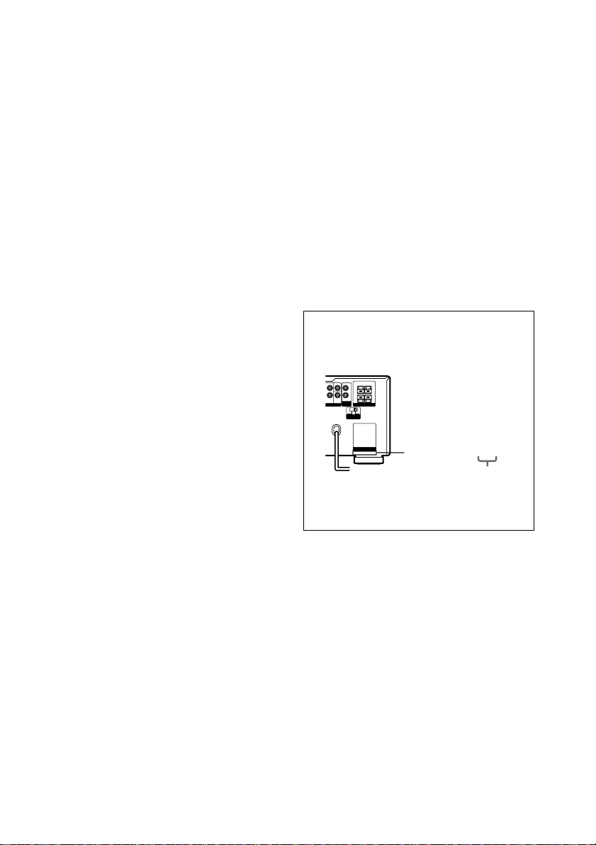
About area codes
The area code of the receiver you purchased is
shown on the lower portion of the rear panel (see
the illustration below).
FRONT B
CENTER
SURROUND
OUT
–
+
L
L
R
SURROUND
R
BACK
SUB
RE OUT SPEAKERS
WOOFER
IMPEDANCE USE 4-16Ω
4 Ω 8 Ω
I
MPEDANCE
SELECTOR
AC OUTLET
Area code
Any differences in operation, according to the
area code, are clearly indicated in the text, for
example, “Models of area code AA only”.
This receiver incorporates Dolby* Digital and Pro
Logic Surround and the DTS** Digital Surround
System.
* Manufactured under license from Dolby
Laboratories.
“Dolby”, “Pro Logic” and the double-D symbol are
trademarks of Dolby Laboratories.
**“DTS”, “DTS-ES Extended Surround” and
“Neo:6” are trademarks of Digital Theater
Systems, Inc.
GB
3

Table of Contents
List of Button Locations and
Reference Pages
Main unit ............................................... 6
Getting Started
1: Check how to hookup your
components ..................................... 8
1a: Connecting components with
digital audio output jacks .......... 10
1b: Connecting components with multi
channel output jacks .................. 13
1c: Connecting components with only
analog audio jacks ..................... 15
2: Connecting the antennas.................. 17
3: Connecting speakers........................ 18
4: Connecting the AC power cord ....... 20
5: Setting up the speakers .................... 21
6: Adjusting the speaker levels and
balance (TEST TONE).................. 23
Amplifier/Tuner Operation
Selecting the component ..................... 24
Listening to multi channel sound
(MULTI CH DIRECT) ................. 25
Listening to FM/AM radio ..................25
Storing FM stations automatically
(AUTOBETICAL)*
Presetting radio stations....................... 27
Using the Radio Data System (RDS)
Changing the display ........................... 31
About the indications in the display .... 32
1
.....................................
1
....
*
27
29
Enjoying Surround Sound
Automatically decoding the input audio
signal (AUTO DECODING)......... 34
Using only the front speakers .............. 34
Selecting a sound field ........................ 35
Enjoying Dolby Pro Logic II and DTS
Neo:6 (2CH MODE) ..................... 38
Selecting the surround back decoding
mode (SB DECODING) ............... 39
Advanced Adjustments and
Settings
Assigning the audio input
(AUDIO SPLIT)............................ 41
Switching the audio input mode for
digital components
(INPUT MODE)............................ 42
Customizing sound fields .................... 43
Adjusting the equalizer........................ 45
Advanced settings................................ 46
Other Operations
Naming preset stations and functions.. 56
Using the Sleep Timer ......................... 57
Selecting the speaker system ............... 57
Listening to the sound in
2
another room*
.....................................................
Recording ............................................ 60
CONTROL A1
/S-LINK control
system............................................ 61
Additional Information
58
Precautions .......................................... 66
Troubleshooting................................... 66
Specifications ...................................... 69
Index ......................................Back cover
*1Models of area code CEL, CEK only.
GB
4
*2Models of area code U, CA only.

GB
5

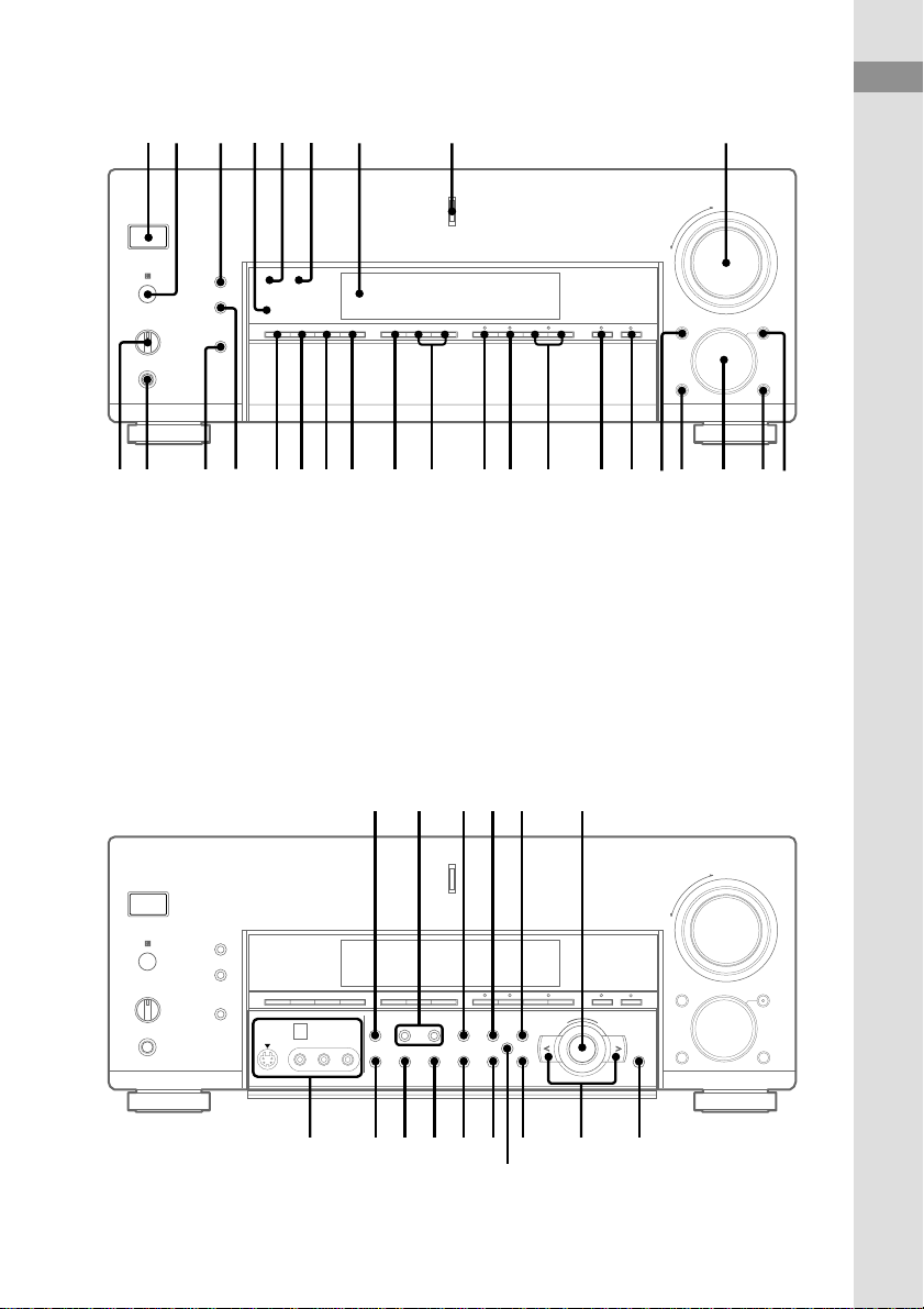
List of Button Locations and Reference Pages
How to use this page
Use this page to find the location of buttons and other
parts of the system that are mentioned in the text.
Main unit
ALPHABETICAL ORDER
A – L
ANALOG DIRECT qh (34)
AUDIO SPLIT 0 (41)
AUTO DEC ql (34)
CINEMA STUDIO EX wd (35)
Cursor buttons ( / ) ej (21,
43–46, 56)
CUSTOMIZE r; (46, 56)
Digital Cinema Sound indicator
5
DIGITAL CONCERT HALL ws
(36)
DIMMER wh (31)
DISPLAY 3 (29, 31)
Display 7
DOOR OPEN qf
ENTER eh (20, 56)
EQ ek (45)
EQUALIZER es (46)
FM/AM wa (25, 26)
FM MODE rf (25)
FUNCTION qs (24, 25, 27, 28,
41, 42, 56)
INPUT MODE qd (42)
IR receptor 2
Jog dial eg (21, 43–46, 56)
LEVEL ef (44)
M – V
MASTER VOLUME 9 (23, 24)
MEMORY e; (27)
MODE +/– qj (36, 37, 45)
MULTI CH DIRECT qg (25)
MULTI CHANNEL DECODING
indicator 8
MUTING qa (24)
NIGHT MODE ra (38)
NIGHT MODE indicator 4
NORMAL SURR
(;PLII/NEO:6) wg (38)
ON SCREEN wj (11, 14, 16)
PHONES jack wk
PRESET TUNING +/– w; (27)
RDS PTY rd (29)
(Models of area code
CEL, CEK only)
SB DEC indicator 6
SET UP ed (21)
SLEEP rd (57)
(Models of area code
SP, KR, E only)
SPEAKERS switch wl (57)
SURR el (43)
SURR BACK DECODING wf
(39)
TEST TONE rs (23)
TUNING +/– ea (25)
(Models of area code U, CA,
SP, KR, E only)
TUNING/PTY SELECT +/– ea
(25, 29)
(Models of area code CEL, CEK
only)
VIDEO 3 INPUT jacks rg (16)
Illustration number
r
PLAY MODE qg (9, 13, 14)
Name of button/part Reference page
RR
NUMBERS AND SYMBOLS
2CH STEREO qk (34)
2ND ROOM rd (58)
(Models of area code U, CA
only)
?/1 (power) 1
GB
6
12 3 456 7 8 9
+
–
List of Button Locations and Reference Pages
ql qkw;wawgwhwjwkwl wf wd ws
Open the front door
v
e; ea es ed ef eg
q;qaqsqdqfqgqhqj
+
–
+–
ra ehekrsrg rdrf
el
ejr;
GB
7

Getting Started
1: Check how to hookup your components
Steps 1a through 1c beginning on page 10 describe how to hook up your components to this receiver.
Before you begin, refer to “Connectable components” below for the pages which describe how to
connect each component.
After hooking up all your components, proceed to “2: Connecting the antennas” (page 17).
Connectable components
Component to be connected Page
DVD/LD player
With digital audio output*
With multi-channel audio output*
With analog audio output only*
TV monitor
With component video input*4*
With S-Video or composite video input only 16
Satellite tuner
With digital audio output*
With analog audio output only*
CD/Super Audio CD player
With digital audio output*
With multi-channel audio output*
With analog audio output only*
MD/DAT deck
With digital audio output*
With analog audio output only*
Cassette deck, analog disc turntable 15
Multi-channel decoder 13
VCR, video camera, video game, etc. 16
1
2
3
5
1
3
1
2
3
1
3
10–11
13–14
10–11
11 or 14
10–11
10–11
12
13
15
12
15
*1Model with a DIGITAL OPTICAL OUTPUT or DIGITAL COAXIAL OUTPUT connector, etc.
*2Model with a MULTI CH OUTPUT connectors, etc. This connection is used to output the audio decoded by the
component’s internal multi-channel decoder through this receiver.
*3Model equipped only with AUDIO OUT L/R jacks, etc.
*4Model with component video (Y, B-Y, R-Y) input jacks
*5Except for models of area code CEL, CEK.
GB
8
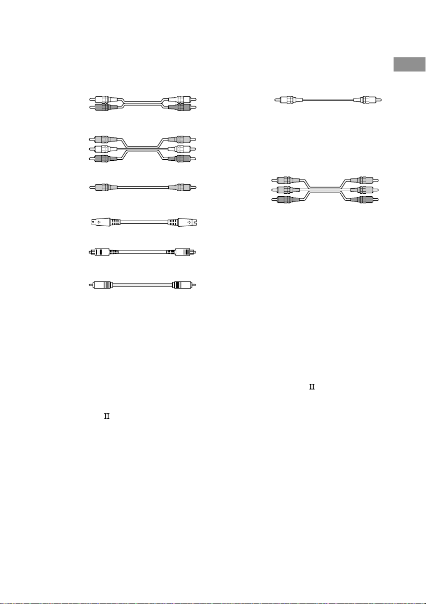
Required cords
The hookup diagrams on the subsequent pages assume the use of the following optional connection
cords (A to H) (not suppiled).
Getting Started
A Audio cord
White (L)
Red (R)
B Audio/video cord
Yellow (video)
White (L/audio)
Red (R/audio)
C Video cord
Yellow
G Monaural audio cord
Black
Tip
Audio cord A can be torn into two monaural audio
cords G.
H Component video cord
(Except for models of area code CEL, CEK)
Green
Blue
Red
D S-video cord
E Optical digital cord
F Coaxial digital cord
Notes
• Turn off the power to all components before making any connections.
• Be sure to make connections firmly to avoid hum and noise.
• When connecting an audio/video cord, be sure to match the color-coded pins to the appropriate jacks on the
components: yellow (video) to yellow; white (left, audio) to white; and red (right, audio) to red.
• When connecting optical digital cords, insert the cord plugs straight in until they click into place.
• Do not bend or tie optical digital cords.
If you have a Sony components with CONTROL A1 /S-LINK
jack
See “CONTROL A1 /S-LINK control system” on page 61.
GB
9
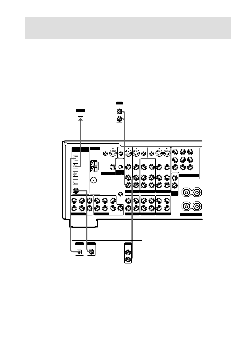
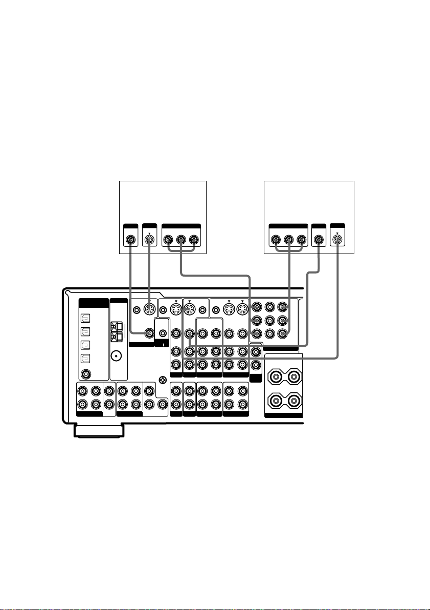
1a: Connecting components with digital audio output
jacks
Hooking up a DVD player, LD player, TV, or satellite tuner
For details on the required cords (A–H), see page 9.
1 Connect the audio jacks.
Satellite tuner
OUTPUT
AUDIO
DIGITAL
(ASSIGNABLE)
FRONT
L
R
MULTI CH IN 2
OUTPUT
DIGITAL
OPTICAL
SURROUND
DVD/LD
OPTICAL
TV/SAT
OPTICAL
MD/DAT
OPTICAL
MD/DAT
OPTICAL
OUT
DVD/LD
COAXIAL
IN
IN
IN
IN
CENTER
SUB
WOOFER
ANTENNA
COAXIAL
FRONT
MULTI CH IN 1
AM
U
FM
75
Ω
CTRL S
IN
MONITOR
SURROUND
S-VIDEO
OUT
VIDEO
CENTER
SURROUND
BACK
OUT
CTRL S
STATUS IN
CONTROL
A1
U
SIGNAL
GND
SUB
WOOFER
L
R
L
R
AE
S-VIDEO
IN
VIDEO
AUDIO
IN
TV/SAT
IN IN
PHONO
S-VIDEO
IN
VIDEO
AUDIO
IN
DVD/LD
CD/SACD
CTRL S
CTRL S
OUT
OUT
S-VIDEO
IN
OUT
VIDEO
VIDEO
VIDEO
AUDIO
AUDIO
AUDIO
IN
OUT
VIDEO 2
OUT
IN
MD/DAT TAPE
OUT
OUT
VIDEO 1
OUT
S-VIDEO
IN
VIDEO
AUDIO
IN
IN
MONITOR OUT
TV/SATINDVD/LD
OUT
COMPONENT VIDEO
L
R
VARIABLE
2ND
ROOM
R
Y
P
B/CB
/B-Y
R/CR
P
/R-Y
IN
SURROUND
L
+
–
SPEA
IMPEDANCE
*
OUTPUT
DIGITAL
OPTICAL
F
OUTPUT
DIGITAL
COAXIAL
*
OUTPUT
AUDIO
OUT
A
L
R
E
DVD/LD player
* Connect to either the DVD/LD COAXIAL IN or the DVD/LD OPTICAL IN jack.
We recommend making connections to the DVD/LD COAXIAL IN jack.
GB
10
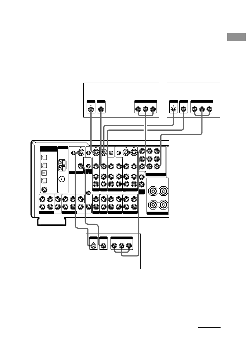
2 Connect the video jacks.
(Except for models of area code CEL, CEK)
The following illustration shows how to connect a TV or satellite tuner and a DVD/LD player with
COMPONENT VIDEO (Y, B-Y, R-Y) output jacks. Connecting a TV with component video input
jacks allows you to enjoy higher quality video.
Notes
• On this receiver, the component video signals cannot be converted to S-video or standard video signals (or vice
versa).
• The on-screen display will not appear on a TV connected to the COMPONENT VIDEO MONITOR OUT jacks
even if you press ON SCREEN.
DVD/LD playerSatellite tuner
OUTPUT
S VIDEO
OUTPUT
VIDEO
OUTPUT OUTPUT
COMPONENT
B-Y
Y
R-Y
OUTPUT
S VIDEO
OUTPUT
VIDEO
R-Y
COMPONENT
B-Y
Y
Getting Started
DIGITAL
(ASSIGNABLE)
FRONT
L
R
MULTI CH IN 2
DVD/LD
OPTICAL
TV/SAT
OPTICAL
MD/DAT
OPTICAL
MD/DAT
OPTICAL
OUT
DVD/LD
COAXIAL
SURROUND
IN
IN
IN
IN
CENTER
SUB
WOOFER
ANTENNA
COAXIAL
FRONT
MULTI CH IN 1
HCDCD
CTRL S
S-VIDEO
IN
VIDEO
AUDIO
IN
TV/SAT
IN IN
PHONO
S-VIDEO
IN
VIDEO
AUDIO
IN
DVD/LD
CD/SACD
INPUT
VIDEO
CTRL S
OUT
OUT
S-VIDEO
IN
OUT
VIDEO
VIDEO
VIDEO
AUDIO
AUDIO
AUDIO
IN
OUT
VIDEO 2
OUT
IN
OUT
MD/DAT TAPE
INPUT
COMPONENT
B-Y
R-Y
OUT
OUT
VIDEO 1
Y
S-VIDEO
VIDEO
AUDIO
H
IN
IN
IN
MONITOR OUT
OUT
L
R
VARIABLE
2ND
ROOM
Y
B/CB
P
/B-Y
R/CR
P
/R-Y
TV/SATINDVD/LD
IN
COMPONENT VIDEO
SURROUND
L
+
–
R
SPEA
IMPEDANCE
CTRL S
CTRL S
STATUS IN
IN
S-VIDEO
OUT
AM
VIDEO
MONITOR
SURROUND
CENTER
SURROUND
BACK
CONTROL
A1
U
SIGNAL
GND
SUB
WOOFER
L
R
U
FM
Ω
75
DC
INPUT
S VIDEO
H
TV monitor
Tip
When the component is equipped with S-video jacks, you can connect the component to the S-VIDEO jacks on
this receiver. In addition, this receiver can convert standard video signals to S-video signals for output from the
MONITOR OUT (S-VIDEO) jacks (models of area code U, CA only).
Note
You can listen to the sound of your TV by connecting your TV’s audio output jacks to the TV/SAT AUDIO IN
jacks on the receiver. In this case, do not connect the TV’s video output jack to the TV/SAT VIDEO IN jack on
the receiver. If you connect a separate satellite tuner, etc., connect both the audio and video output jacks to the
receiver as shown above.
continued
11
GB
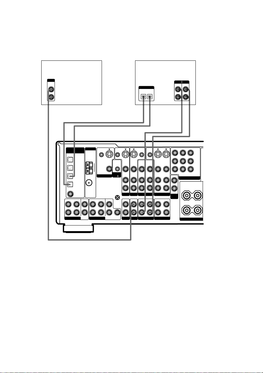
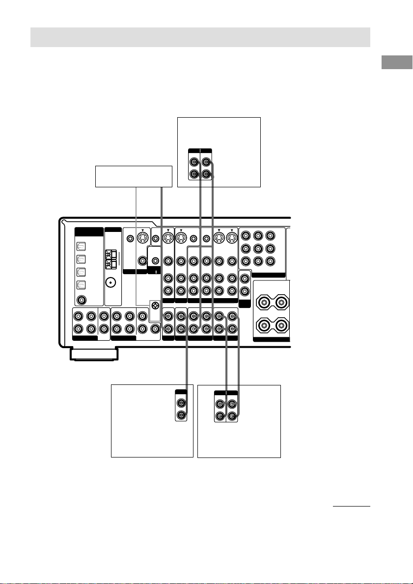
1a: Connecting components with digital audio output jacks (continued)
Hooking up a CD/Super Audio CD player and MD/DAT deck
For details on the required cords (A–H), see page 9.
CD/Super Audio CD
player
OUTPUT
AUDIO
OUT
L
R
A
DIGITAL
ANTENNA
(ASSIGNABLE)
DVD/LD
OPTICAL
IN
TV/SAT
OPTICAL
IN
MD/DAT
OPTICAL
IN
MD/DAT
OPTICAL
OUT
COAXIAL
DVD/LD
COAXIAL
IN
FRONT
SURROUND
CENTER
L
R
MULTI CH IN 2
SUB
WOOFER
CTRL S
IN
AM
U
MONITOR
FM
75
Ω
FRONT
SURROUND
MULTI CH IN 1
S-VIDEO
OUT
VIDEO
CENTER
SURROUND
BACK
CTRL S
STATUS IN
CONTROL
A1
U
SIGNAL
GND
SUB
WOOFER
MD/DAT deck
DIGITAL
OPTICAL
OUT
IN
EE AA
l
INOUT
l
CTRL S
CTRL S
OUT
OUT
S-VIDEO
S-VIDEO
IN
OUT
VIDEO
VIDEO
AUDIO
AUDIO
AUDIO
IN
OUT
VIDEO 2
OUT
IN
MD/DAT TAPE
OUT
VIDEO
OUT
VIDEO 1
OUT
VIDEO
AUDIO
IN
IN
IN
L
R
TV/SAT
S-VIDEO
IN
VIDEO
AUDIO
IN
IN IN
PHONO
S-VIDEO
IN
VIDEO
AUDIO
IN
DVD/LD
CD/SACD
INPUT OUTPUT
LINE
l
MONITOR OUT
TV/SATINDVD/LD
OUT
COMPONENT VIDEO
L
R
VARIABLE
2ND
ROOM
R
LINE
L
R
l
INOUT
Y
P
B/CB
/B-Y
P
R/CR
/R-Y
IN
SURROUND
L
+
–
SPEA
IMPEDANCE
If you want to connect several digital components, but cannot find an unused
input
See “Assigning the audio input (AUDIO SPLIT)” (page 41).
Tips
• All the digital audio jacks are compatible with 32 kHz, 44.1 kHz, 48 kHz and 96 kHz sampling frequencies.
• You can also connect an LD player with a DOLBY DIGITAL RF OUT jack via an RF demodulator (You cannot
connect an LD player’s DOLBY DIGITAL RF OUT jack directly to this unit’s digital input jacks). Refer to the
operating instructions supplied with the RF demodulator.
Notes
• No sound is output when playing a Super Audio CD disc on a Super Audio CD player connected to the DVD/LD
COAXIAL IN jack on this receiver. Connect the player to the analog input jacks (CD/SACD IN jacks). Refer to
the operating instructions supplied with the Super Audio CD player.
• You cannot make digital recordings of digital multi channel surround signals.
GB
12
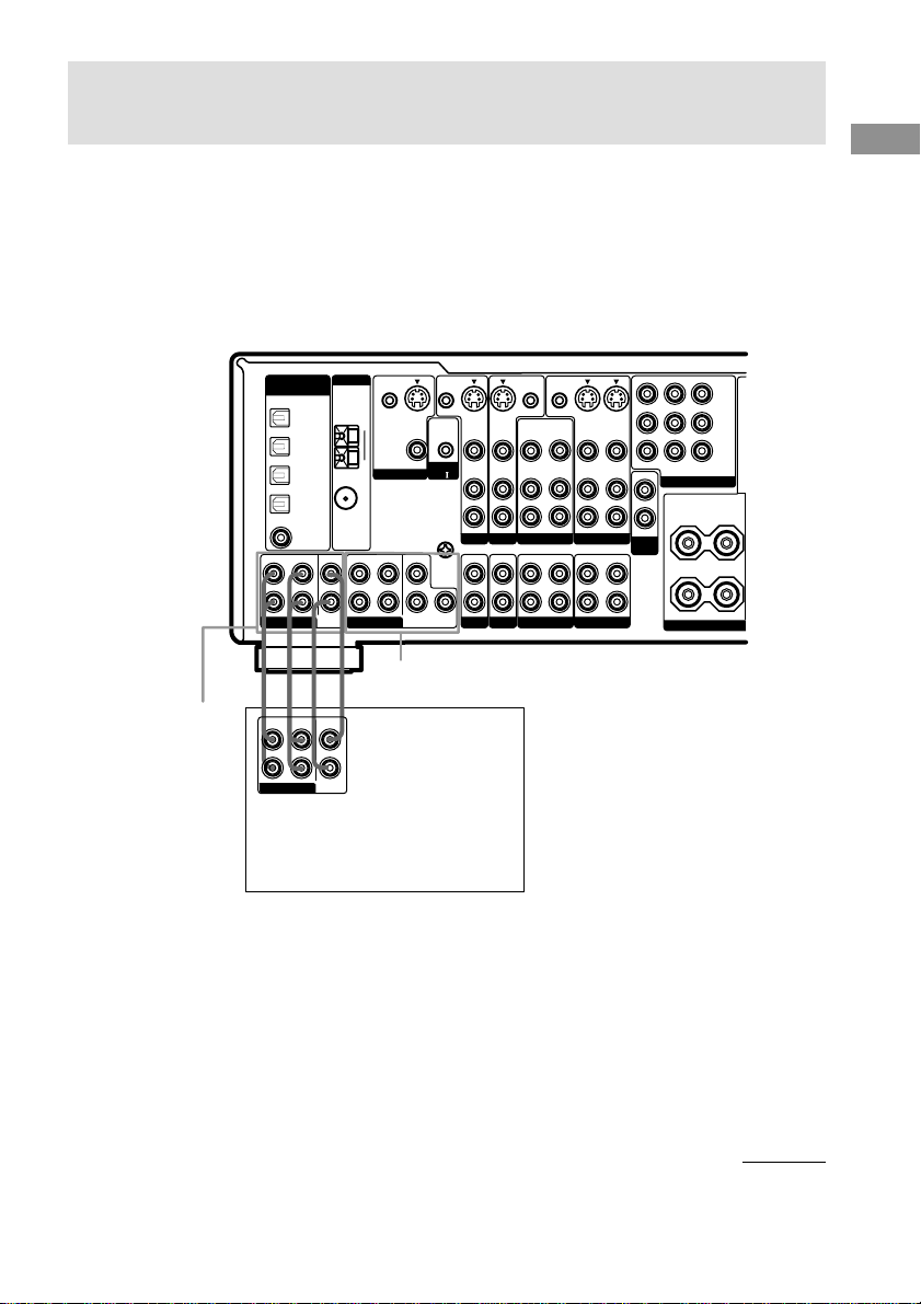
1b: Connecting components with multi channel output
jacks
1 Connect the audio jacks.
If your DVD/LD and CD/Super Audio CD players are equipped with multi channel decoder, you can
connect them to this receiver’s MULTI CH IN jacks to enjoy the sound of the connected
component’s multi channel decoder. Alternatively, the multi channel input jacks can be used to
connect an external multi channel decoder.
For details on the required cords (A–H), see page 9.
CTRL S
S-VIDEO
IN
VIDEO
AUDIO
IN
TV/SAT
IN IN
PHONO
S-VIDEO
IN
VIDEO
AUDIO
IN
DVD/LD
CD/SACD
CTRL S
OUT
OUT
S-VIDEO
IN
OUT
VIDEO
VIDEO
AUDIO
AUDIO
AUDIO
IN
OUT
VIDEO 2
OUT
IN
MD/DAT TAPE
OUT
VIDEO
OUT
VIDEO 1
OUT
S-VIDEO
VIDEO
AUDIO
IN
IN
IN
MONITOR OUT
OUT
VARIABLE
2ND
ROOM
L
R
Y
P
B/CB
/B-Y
P
R/CR
/R-Y
TV/SATINDVD/LD
IN
COMPONENT VIDEO
SURROUND
L
+
–
R
SPEA
IMPEDANCE
MULTI CH IN 2
DIGITAL
ANTENNA
CTRL S
COAXIAL
SUB
IN
AM
U
MONITOR
FM
Ω
75
FRONT
SURROUND
MULTI CH IN 1
S-VIDEO
OUT
VIDEO
CENTER
SURROUND
BACK
(ASSIGNABLE)
FRONT
L
R
MULTI CH IN 2
DVD/LD
OPTICAL
TV/SAT
OPTICAL
MD/DAT
OPTICAL
MD/DAT
OPTICAL
DVD/LD
COAXIAL
SURROUND
IN
IN
IN
OUT
IN
CENTER
WOOFER
MULTI CH IN 1
AAG G
FRONT
SURROUND
CENTER
L
R
MULTI CH OUT
SUB
WOOFER
DVD/LD player,
CD/Super Audio CD player,
Multichannel decoder, etc.
CTRL S
STATUS IN
CONTROL
A1
U
SIGNAL
GND
SUB
WOOFER
L
R
Getting Started
Tips
• This connection also allows you to enjoy software with multi-channel audio recorded in formats other than the
Dolby Digital, DTS and MPEG-2.
• Make connections to either the MULTI CH IN 1 or 2 jacks according to the number of audio output jacks of the
component.
Note
DVD and Super Audio CD players do not have SURR BACK terminals.
continued
13
GB
1b: Connecting components with multi channel output jacks (continued)
2 Connect the video jacks.
(Except for models of area code CEL, CEK)
The following illustration shows how to connect a DVD or LD player with COMPONENT VIDEO
(Y, B-Y, R-Y) output jacks. Connecting a TV with component video input jacks allows you to enjoy
higher quality video.
Notes
• On this receiver, the component video signals cannot be converted to S-video or standard video signals (or vice
versa).
• The on-screen display will not appear on a TV connected to the COMPONENT VIDEO MONITOR OUT jacks
even if you press ON SCREEN.
DVD/LD player
COMPONENT
B-Y
R-Y
P
/B-Y
P
/R-Y
TV/SATINDVD/LD
IN
COMPONENT VIDEO
L
R
SURROUND
L
+
R
IMPEDANCE
Y
B/CB
R/CR
–
SPEA
OUTPUT
OUTPUT
VIDEO
Y
S VIDEO
CDH
DIGITAL
(ASSIGNABLE)
FRONT
L
R
MULTI CH IN 2
DVD/LD
OPTICAL
TV/SAT
OPTICAL
MD/DAT
OPTICAL
MD/DAT
OPTICAL
DVD/LD
COAXIAL
SURROUND
ANTENNA
IN
AM
IN
U
IN
FM
75
Ω
OUT
COAXIAL
IN
CENTER
FRONT
SUB
WOOFER
MULTI CH IN 1
TV monitor
INPUT
VIDEO COMPONENT
S VIDEO
CTRL S
IN
S-VIDEO
OUT
VIDEO
MONITOR
SURROUND
CENTER
SURROUND
BACK
CTRL S
STATUS IN
CONTROL
A1
U
SIGNAL
GND
SUB
WOOFER
R-Y
L
R
INPUT OUTPUTINPUT
S-VIDEO
IN
VIDEO
AUDIO
IN
TV/SAT
IN IN
PHONO
B-Y
HCD
S-VIDEO
IN
VIDEO
AUDIO
IN
DVD/LD
CD/SACD
Y
CTRL S
CTRL S
OUT
OUT
S-VIDEO
OUT
IN
OUT
VIDEO
VIDEO
VIDEO
AUDIO
AUDIO
AUDIO
OUT
IN
OUT
VIDEO 2
OUT
IN
OUT
MD/DAT TAPE
VIDEO 1
S-VIDEO
VIDEO
AUDIO
IN
IN
IN
MONITOR OUT
OUT
VARIABLE
2ND
ROOM
Tip
When the component is equipped with S-video jacks, you can connect the component to the S-VIDEO jacks on
this receiver. In addition, this receiver can convert standard video signals to S-video signals for output from the
MONITOR OUT (S-VIDEO) jacks (models of area code U, CA only).
Note
You can listen to the sound of your TV by connecting your TV’s audio output jacks to the TV/SAT AUDIO IN
jacks on the receiver. In this case, do not connect the TV’s video output jack to the TV/SAT VIDEO IN jack on
the receiver. If you connect a separate satellite tuner, etc., connect both the audio and video output jacks to the
receiver as shown above.
14
GB
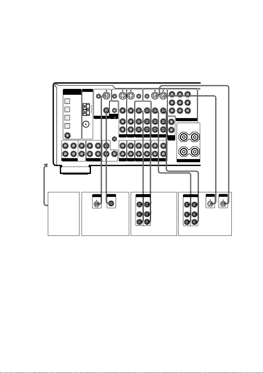
1c: Connecting components with only analog audio jacks
Hooking up audio components
For details on the required cords (A–H), see page 9.
MD/DAT deck
INPUT OUTPUT
LINE
LINE
Turntable
A
ç
CTRL S
S-VIDEO
IN
VIDEO
AUDIO
IN
TV/SAT
IN IN
PHONO
S-VIDEO
IN
VIDEO
AUDIO
IN
DVD/LD
CD/SACD
CTRL S
OUT
OUT
OUT
VIDEO
VIDEO
AUDIO
AUDIO
OUT
VIDEO 2
OUT
MD/DAT TAPE
(ASSIGNABLE)
FRONT
L
R
MULTI CH IN 2
DIGITAL
SURROUND
DVD/LD
OPTICAL
TV/SAT
OPTICAL
MD/DAT
OPTICAL
MD/DAT
OPTICAL
OUT
DVD/LD
COAXIAL
IN
IN
IN
IN
CENTER
SUB
WOOFER
ANTENNA
COAXIAL
FRONT
MULTI CH IN 1
CTRL S
CTRL S
STATUS IN
IN
S-VIDEO
OUT
AM
VIDEO
MONITOR
SURROUND
CENTER
SURROUND
BACK
CONTROL
A1
U
SIGNAL
GND
SUB
WOOFER
L
R
U
FM
75
Ω
Getting Started
L
R
AA
ç
INOUT
Y
S-VIDEO
S-VIDEO
IN
OUT
IN
VIDEO
VIDEO
MONITOR OUT
AUDIO
AUDIO
IN
OUT
IN
IN
VIDEO 1
OUT
OUT
VARIABLE
2ND
ROOM
IN
P
/B-Y
P
/R-Y
TV/SATINDVD/LD
IN
COMPONENT VIDEO
L
R
SURROUND
L
+
R
IMPEDANCE
B/CB
R/CR
–
SPEA
ç
INOUT
A
OUTPUT
LINE
CD/Super Audio CD
L
R
AA
INPUT OUTPUT
LINE
LINE
L
R
Tape deck
ç
player
Note
If your turntable has a ground wire, connect it to the U SIGNAL GND terminal.
continued
15
GB
1c: Connecting components with only analog audio jacks (continued)
Hooking up video components
If you connect your TV to the MONITOR jacks, you can watch the video from the selected input
(function) (page 24). In addition, you can display the SET UP, SURROUND, LEVEL, EQ
parameters and the selected sound field by pressing ON SCREEN.
For details on the required cords (A–H), see page 9.
CTRL S
S-VIDEO
IN
VIDEO
AUDIO
IN
TV/SAT
IN IN
PHONO
S-VIDEO
IN
VIDEO
AUDIO
IN
DVD/LD
CD/SACD
CTRL S
OUT
OUT
S-VIDEO
OUT
IN
OUT
VIDEO
VIDEO
VIDEO
AUDIO
AUDIO
AUDIO
OUT
IN
OUT
VIDEO 2
OUT
IN
OUT
MD/DAT TAPE
VIDEO 1
S-VIDEO
VIDEO
AUDIO
IN
IN
IN
MONITOR OUT
TV/SATINDVD/LD
OUT
COMPONENT VIDEO
L
R
VARIABLE
2ND
L
ROOM
R
+
IN
SURROUND
Y
B/CB
P
/B-Y
R/CR
P
/R-Y
–
SPEA
IMPEDANCE
Ç
To the
VIDEO 3
INPUT jacks
DIGITAL
(ASSIGNABLE)
FRONT
L
R
MULTI CH IN 2
DVD/LD
OPTICAL
TV/SAT
OPTICAL
MD/DAT
OPTICAL
MD/DAT
OPTICAL
DVD/LD
COAXIAL
SURROUND
CTRL S
IN
MONITOR
S-VIDEO
OUT
VIDEO
CENTER
SURROUND
BACK
CTRL S
STATUS IN
CONTROL
A1
U
SIGNAL
GND
SUB
WOOFER
L
R
ANTENNA
IN
AM
IN
U
IN
FM
75
Ω
OUT
COAXIAL
IN
CENTER
FRONT
SURROUND
SUB
WOOFER
MULTI CH IN 1
Ç
OUTIN
B, D, E
Camcorder
or TV
game
Ç
INOUT
Ç
INPUT
S VIDEO
INPUT
VIDEO
BCDBBBDD
OUTPUTINPUT
VIDEO
VIDEO
OUT
IN
AUDIO
AUDIO
OUT
IN
L
R
TV monitor VCR VCR
VIDEO
AUDIO
IN
IN
Ç
OUTPUTINPUT
VIDEO
AUDIO
Ç
OUT
OUT
L
R
Tip
When the component is equipped with S-video jacks, you can connect the component to the S-VIDEO jacks on
this receiver. In addition, this receiver can convert standard video signals to S-video signals for output from the
MONITOR OUT (S-VIDEO) jacks (models of area code U, CA only).
Note
You can listen to the sound of your TV by connecting your TV’s audio output jacks to the TV/SAT AUDIO IN
jacks on the receiver. In this case, do not connect the TV’s video output jack to the TV/SAT VIDEO IN jack on
the receiver. If you connect a separate satellite tuner, etc., connect both the audio and video output jacks to the
receiver as shown above.
GB
16
INOUT
OUTPUT
S VIDEO
INPUT
S VIDEO
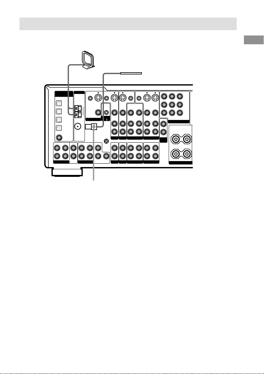
2: Connecting the antennas
Connect the supplied AM loop antenna and FM wire antenna.
AM loop antenna
(supplied)
FM wire antenna
(supplied)
CTRL S
S-VIDEO
IN
VIDEO
AUDIO
IN
TV/SAT
IN IN
PHONO
S-VIDEO
IN
VIDEO
AUDIO
IN
DVD/LD
CD/SACD
CTRL S
OUT
OUT
S-VIDEO
OUT
IN
VIDEO
VIDEO
VIDEO
AUDIO
AUDIO
AUDIO
IN
OUT
VIDEO 2
OUT
IN
OUT
MD/DAT TAPE
OUT
OUT
DIGITAL
(ASSIGNABLE)
FRONT
L
R
MULTI CH IN 2
DVD/LD
OPTICAL
TV/SAT
OPTICAL
MD/DAT
OPTICAL
MD/DAT
OPTICAL
DVD/LD
COAXIAL
SURROUND
ANTENNA
IN
AM
IN
U
IN
FM
75
Ω
OUT
COAXIAL
IN
CENTER
FRONT
SUB
WOOFER
MULTI CH IN 1
CTRL S
IN
MONITOR
SURROUND
S-VIDEO
OUT
VIDEO
CENTER
SURROUND
BACK
CTRL S
STATUS IN
CONTROL
A1
U
SIGNAL
GND
SUB
WOOFER
L
R
*
* The shape of the connector varies depending on the area code.
VIDEO 1
S-VIDEO
IN
VIDEO
AUDIO
IN
IN
MONITOR OUT
TV/SATINDVD/LD
OUT
COMPONENT VIDEO
L
R
VARIABLE
2ND
L
ROOM
R
+
IN
SURROUND
Y
P
B/CB
/B-Y
R/CR
P
/R-Y
–
SPEA
IMPEDANCE
Getting Started
Notes
• To prevent noise pickup, keep the AM loop antenna away from the receiver and other components.
• Be sure to fully extend the FM wire antenna.
• After connecting the FM wire antenna, keep it as horizontal as possible.
• Do not use the U SIGNAL GND terminal for grounding the receiver.
17
GB
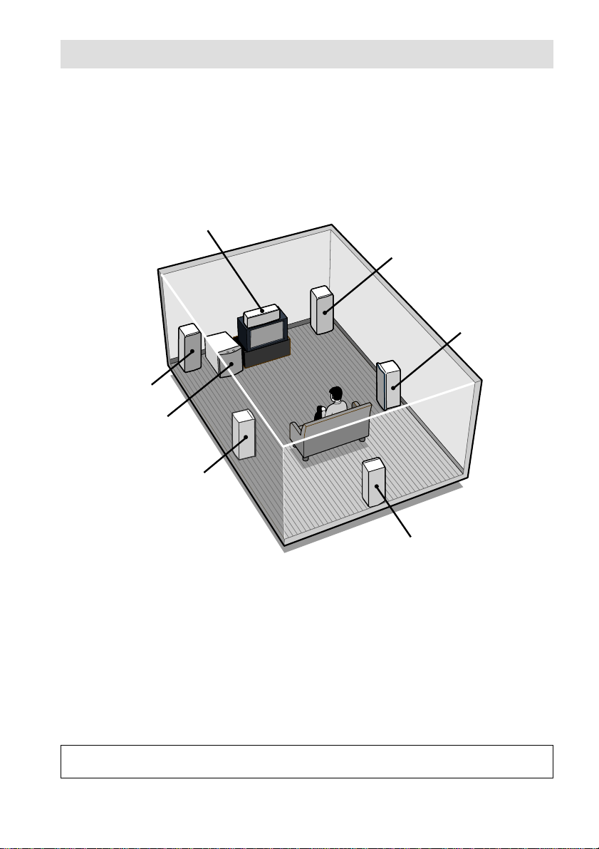
3: Connecting speakers
Connect your speakers to the receiver. This receiver alows you to use a 6.1 channel speaker system.
To fully enjoy theater-like multi channel surround sound requires five speakers (two front speakers, a
center speaker, and two surround speakers) and a sub woofer (5.1 channel).
You can enjoy high fidelity reproduction of DVD software recorded in the Surround EX format if
you connect one additional surround back speaker (6.1 channel). (See “Selecting the surround back
decoding mode” on page 39.)
Example of 6.1 channel speaker system configuration
Center speaker
Front speaker (R)
Surround speaker (R)
Front speaker (L)
Active sub woofer
Surround speaker (L)
Surround back speaker
Tip
Since the active sub woofer does not emit highly directional signals, you can place it wherever you want.
Speaker impedance
To enjoy the best possible multi channel surround, connect speakers with a nominal impedance of
8 ohms or higher to the FRONT, CENTER, SURROUND and SURROUND BACK terminals, and
set the IMPEDANCE SELECTOR to “8Ω”. Refer to the operating instructions supplied with your
speakers if you are not sure of their impedance. (This information is often on the back of the
speaker.)
Alternatively, you may connect speakers with nominal impedances between 4 and 8 ohms to any or
all of the speaker terminals. However, be sure to set the IMPEDANCE SELECTOR to “4Ω” if you
connect even one speaker with a nominal impedance between 4 and 8 ohms.
Note
Be sure to turn the power off before adjusting the IMPEDANCE SELECTOR.
GB
18
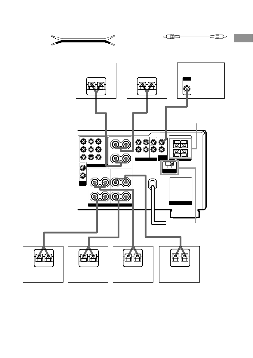
Required cords
A Speaker cords (not supplied)
(+)
(–)
Front speaker (R)
Ee
MONITOR OUT
OUT
L
R
VARIABLE
2ND
ROOM
A
Y
P
B/CB
/B-Y
P
R/CR
/R-Y
TV/SATINDVD/LD
IN
COMPONENT VIDEO
SURROUND
L
+
–
R
SPEAKERS
IMPEDANCE USE 4-16Ω
L
R
B Monaural audio cord (not supplied)
Black
Front speaker (L)
Ee
A
FRONT A
–
CENTER
– +
SURROUND BACK
FRONT CENTER
SURROUND
L
+
R
PRE OUT SPEAKERS
SURROUND
BACK
WOOFER
OUT
SUB
R
4 Ω 8 Ω
I
MPEDANCE
SELECTOR
FRONT B
–
L
AC OUTLET
IMPEDANCE USE 4-16Ω
Active sub woofer
INPUT
AUDIO
IN
B
SPEAKERS
FRONT B*
+
Getting Started
IMPEDANCE
SELECTOR
A
E
Surround speaker
(R)
e
E
A
Surround back
speaker
E
e
Surround speaker
(L)
A
e
E
A
e
Center speaker
* (Models of area codes U, CA, CEL, CEK, SP, KR only.) You can select the front speakers you want to use with
the SPEAKERS switch. For details, see “Selecting the speaker system” (page 57).
19
GB
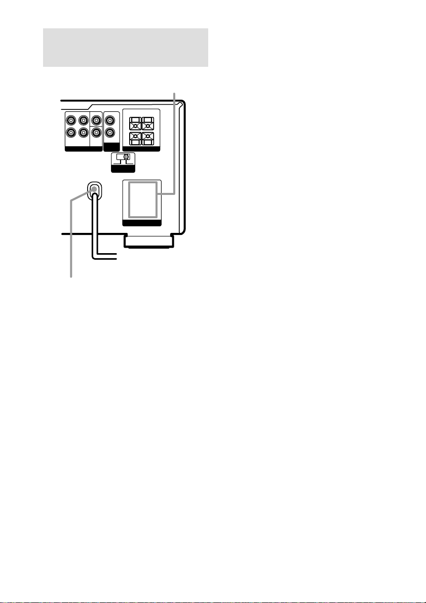
4: Connecting the AC
power cord
AC OUTLET
FRONT CENTER
SURROUND
L
R
SURROUND
BACK
PRE OUT SPEAKERS
OUT
SUB
WOOFER
4 Ω 8 Ω
FRONT B
–
L
R
I
MPEDANCE
SELECTOR
AC OUTLET
To a wall outlet
b
+
IMPEDANCE USE 4-16Ω
AC power cord
* Except for models of area code KR.
The configuration, shape, and number of AC outlets
vary according to the model and country to which
the receiver is shipped.
Notes
• The AC OUTLET(s) on the rear of the receiver is a
switched outlet, which supplies power to the
connected component only while the receiver is
turned on.
• Make sure that the total power consumption of the
component(s) connected to the receiver’s AC
OUTLET(s) does not exceed the wattage stated on
the rear panel. Do not connect high-wattage
electrical home appliances such as electric irons,
fans, or TVs to this outlet. This may cause a
malfunction.
*
Performing initial setup
operations
Before using the receiver for the first time,
initialize the receiver by performing the
following procedure.
This procedure can also be used to return
settings you have made to their factory
defaults.
1 Press ?/1 to turn off the receiver.
2 Hold down ?/1 for 5 seconds.
“ENTER to Clear All” appears in the
display.
3 Press DOOR OPEN to open the door of
the front panel, then press ENTER.
After “MEMORY CLEARING...” appears
in the display for a while, “MEMORY
CLEARED!” appears.
The following are reset to their factory
settings.
• All settings in the SET UP,
CUSTOMIZE, SURROUND, LEVEL,
and EQ menus.
• The sound field memorized for each
function and preset station.
• All preset stations.
• All index names for functions and
preset stations.
20
GB

5: Setting up the speakers
Use the SET UP menu to set the types and sizes
of the speakers connected to the receiver.
1 Press ?/1 to turn on the receiver.
2 Press SET UP.
The SET UP parameter appears in the
display.
3 Press the cursor buttons ( or ) to
select the speaker.
For details, see “Speaker setup parameters”
below.
Notes
• Certain setup parameters may be dimmed in the
display. This means that the selected parameter
is either unavailale or fixed and unchangeable
due to sound field (pages 35–37) or other
settings.
• Some speaker settings may appear dimmed in
the display. This means that they have been
changed automatically due to other speaker
settings. The dimmed settings may or may not
be adjustable.
4 Turn the jog dial to select the
parameter.
5 Repeat steps 3 and 4 until you have set
all of the items that follow.
Speaker setup parameters
The initial setting is underlined.
x FRONT SP (Front speaker size)
• LARGE
If you connect large speakers that will
effectively reproduce bass frequencies, select
“LARGE”. Normally, select “LARGE”.
• SMALL
If the sound is distorted, or you feel a lack of
surround effects when using multi channel
surround sound, select “SMALL” to activate
the bass redirection circuitry and output the
front channel bass frequencies from the sub
woofer. When the front speakers are set to
“SMALL”, the center, surround, and surround
back speakers are also automatically set to
“SMALL” (unless previously set to “NO”).
x CENTER SP (Center speaker size)
• LARGE
If you connect a large speaker that will
effectively reproduce bass frequencies, select
“LARGE”. Normally, select “LARGE”.
However, if the front speakers are set to
“SMALL”, you cannot set the center speaker to
“LARGE”.
• SMALL
If the sound is distorted, or you feel a lack of
surround effects when using multi channel
surround sound, select “SMALL” to activate
the bass redirection circuitry and output the
center channel bass frequencies from the front
speakers (if set to “LARGE”) or sub woofer.
• NO (for all sources except MULTI CH 1/2)
If you did not connect a center speaker, select
“NO”. The sound of the center channel will be
output from the front speakers (digital
downmix).
• MIX (for all sources except MULTI CH 1/2)
If you did not connect a center speaker but want
to downmix the center channel audio, select
“MIX” (page 25).
This is only active when the front, surround,
and surround back speakers are set to
“LARGE” (ANALOG DOWNMIX). When all
speakers are not set to “LARGE”, the center
channel will be downmixed digitally (DIGITAL
DOWNMIX).
* When using MULTI CH 1/2 sources, the sound
of the center channel is output from the front
speakers if you select either “NO” or “MIX”.
continued
Getting Started
21
GB

5: Setting up the speakers
(continued)
x SURROUND SP (Surround speaker
size)
• LARGE
If you connect large speakers that will
effectively reproduce bass frequencies, select
“LARGE”. Normally, select “LARGE”.
However, if the front speakers are set to
“SMALL”, you cannot set the surround
speakers to “LARGE”.
• SMALL
If the sound is distorted, or you feel a lack of
surround effects when using multi channel
surround sound, select “SMALL” to activate
the bass redirection circuitry and output the
surround channel bass frequencies from the sub
woofer or other “LARGE” speakers.
• NO
If you did not connect surround speakers, select
“NO”. When the surround speakers are set to
“NO”, the surround back speakers are also
automatically set to “NO”.
x SURR BACK SP (Surround back
speaker size)
When the surround speakers are set to “NO”,
the surround back speaker is also automatically
set to “NO” and the setting cannot be changed.
• LARGE
If you connect a large speaker that will
effectively reproduce bass frequencies, select
“LARGE”. Normally, select “LARGE”.
However, if the front speakers are set to
“SMALL”, you cannot set the surround back
speaker to “LARGE”.
• SMALL
If the sound is distorted, or you feel a lack of
surround effects when using multi channel
surround sound, select “SMALL” to activate
the bass redirection circuitry and output the
surround back channel bass frequencies from
the front speakers (if set to “LARGE”) or sub
woofer.
• NO
If you did not connect a surround back speaker,
select “NO”.
Tip
The LARGE and SMALL settings for each speaker
determine whether or not the internal sound processor
will cut the bass signal from that channel. When the
bass is cut from a channel, the bass redirection
circuitry sends the corresponding bass frequencies to
the sub woofer or other “LARGE” speakers.
However, since bass has a certain amount of
directionality, it best not to cut them, if possible.
Therefore, even when using small speakers, you can
set them to “LARGE” if you want to output the bass
frequencies from that speaker. On the other hand, if
you are using a large speaker, but prefer not to have
bass frequencies output from that speaker, set it to
“SMALL”.
If the overall sound level is lower than you prefer, set
all speakers to “LARGE”. If there is not enough bass,
you can use the equalizer to boost the bass levels. To
adjust the equalizer, see page 45.
x SUB WOOFER (Sub woofer selection)
• YES
If you connect a sub woofer, select “YES”.
• NO
If you did not connect a sub woofer, select
“NO”. This activates the bass redirection
circuitry and outputs the LFE signals from other
speakers.
Tip
In order to take full advantage of the Dolby Digital
bass redirection circuitry, we recommend setting the
sub woofer’s cut off frequency as high as possible.
For advanced speaker setups
Use the CUSTOMIZE menu and set “MENU
EXPAND” to “ON”. This enables advanced
setups including those of the distances to the
speakers and heights of the speakers.
For details on “MENU EXPAND”, see page
46. For details on how to set the items, see page
48.
22
GB
 Loading...