

Page 1

4-247-241-16(1)
FM Stereo
FM/AM Receiver
Operating Instructions
Owner’s Record
The model and serial numbers are lo cated on the rear of th e unit. Record th e seria l
number in the spac e pr ovided below. Refer to th em w henever you call upon your
Sony dealer regarding this product.
Model No.
Serial No.
STR-DA2000ES
STR-DB2000
©2003 Sony Corporation
Page 2
WARNING
To prevent fire or shock hazard, do not
expose the unit to rain or mo ist u r e.
To prevent fire, do not cover the ventil at ion of the
apparatus with news papers, table-cloths, curtains, etc.
And don’t place lighted candle s on the apparatus.
To prevent fire or shock hazard, do not place obje c ts
filled with liquids, such as vases , on the ap pa ratus.
Do not install the appliance in a confined space,
such as a bookcase or built-in cabi ne t.
Don’t throw away batter ie s w ith
general house waste; dispose of
them correctly as chemical waste.
For customers in the United States
This symbol is int en ded to alert
the user to the presence of
uninsulated “dangerous voltage”
within the product’s enclosure
that may be of sufficient
magnitude to consti tut e a ris k of
electric shock to persons.
This symbol is int en ded to alert
the user to the presence of
important operating and
maintenance (servicing)
instructions in the literature
accompanying the appliance.
WARNING
This equipment has been tested and found to comply with the
limits for a Class B digital device, pursuant to Part 15 of the
FCC Rules. These limits are designed to provide reasonable
protection against harmful interference in a residential
installation. This equipment generates, uses, and can radiate
radio frequency energy and, if not installed and used in
accordance with the instructions, may cause harmful
interference to radio communications. However, there is no
guarantee that interference will not occur in a particular
installation. If this equipment does cause harmful
interference to radio or television reception, which can be
determined by turning the equipment off and on, the user is
encouraged to try to correct the interference by one or more
of the following measures:
– Reorient or relocate the rece iv i ng an tenna.
– Increase the separation betwe e n the equi pment and
receiver.
– Connect the equipment into an outlet on a circuit
different from tha t to w hich the receiver is
connected.
– Consult the dealer or an experie nc e d radio/TV
technician for help.
CAUTION
You are cautioned that any changes or modification not
expressly approved in this manual could void your
authority to operate this equipm ent .
Note to CATV system installer:
This reminder is provided to call CATV system
installer’s attention to Article 820-40 of the NEC that
provides guidelines for proper ground ing a nd, in
particular, specifies that the cable ground shall be
connected to the grounding system of the building, as
close to the point of cable entry as practical.
For customer in Canada
CAUTION
TO PREVENT ELECTRIC SHOCK, MATCH WIDE
BLADE OF PLUG TO WIDE SLOT, FULLY
INSERT.
Except for European model
ENERGY STAR® is a U.S. registered
mark. As an ENERGY STAR®
partner, Sony Corporation has
determined that this product meets the
ENERGY STAR® guidelines for
energy efficiency.
GB
2
Page 3
About This Manual
S
• The instructions in this manual are for model STRDA2000ES and STR-DB2000. Check your model
number by looking at the lower right corner of the
front panel. In this manual, STR-DB2000 (area code
CEL) is used for illustration purposes unless stated
otherwise. Any difference in operation is clear ly
indicated in the text, for example, “STR-DA2000ES
only”.
• The instructions in this manual describe the controls
on the receiver. You can also use the controls on the
supplied remote if they ha ve th e sam e or si milar
names as those on the receiver. For details on the use
of your remote, see the separate operating
instructions supplied w it h the remote.
– STR-DA2000ES
RM-LG112
–STR-DB2000
RM-PP412
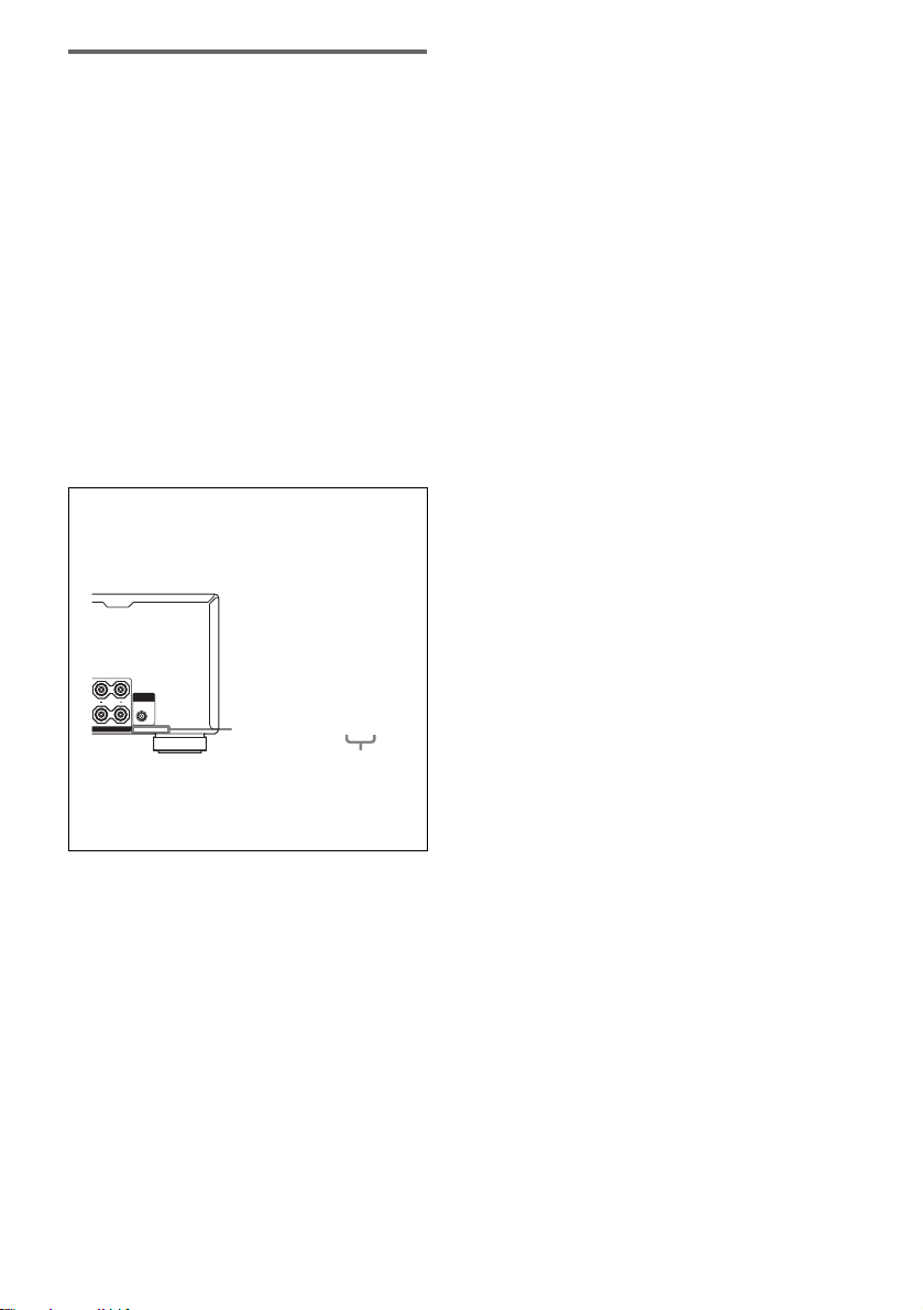
About area codes
The area code of the receiver you purchased is
shown on th e lo wer portion of the rear panel (see
the illustration below).
SUB
L
WOOFER
AUDIO
OUT
L
PEAKERS
4-XXX-XXX-XX AA
Area code
Any differences in operation, according t o the area
code, are clearly indicated in the text, for example,
“Models of area code AA only”.
This receiver incorporates Dolby* Digital and Pro
Logic Surround and the DTS** Digital Surrou nd
System.
* Manufactured under license fr om Dol by
Laboratories.
“Dolby”, “Pro Logic” and the double-D symbol are
trademarks of Dolby Laboratories.
**“DTS”, “DTS-ES Exten de d Surround”, and
“Neo:6” are trademark s of Digital T heater Syst ems,
Inc.
GB
3
Page 4

Table of Contents
Getting Started
1: Check how to hookup yo ur
components.......................................6
1a: Connecting components with
digital audio output jacks...........8
1b: Connecting components with
multi channel output jacks........11
1c: Connecting compon ents with only
analog audio jacks....................13
2: Connecting the antennas...................15
3: Connecting speakers.........................16
4: Connecting the AC power cord ........19
5: Setting up the speakers .....................20
6: Adjusting the speaker levels and
balance............................................23
— TEST TONE
Amplifier Operation
Selecting the component.......................24
Listening to multi channel so un d..........25
— MULTI CH IN
Listening to FM/AM radio....................25
Storing FM stations automatically........26
— AUTOBETICAL
(Models of area code CEL only)
Presetting radio stations........................27
Using the Radio Data System (RDS)....28
(Models of area code CEL only)
Changing the display.............................29
About the indications in the display......30
Switching the audio input mode for digital
components.....................................38
— INPUT MODE
Customizing sound fields..................... 38
Adjusting the equalizer.........................40
Advanced settings.................................40
Custom install mode .............................44
(Models of area code U, CA only)
Other Operations
Naming preset stations and inputs........ 45
Using the Sleep Timer..........................46
Selecting the speaker system................46
Recording .............................................47
Listening to the sound in another zone. 48
(Models of area code U, CA only)
CONTROL A1II Control System........ 49
Additional Information
Precautions ...........................................51
Troubleshooting....................................52
Specifications .......................................55
List of button locations and reference
pages...............................................58
Index........................................back cover
Enjoying Surround Sound
Using only the front speakers......... ......32
Enjoying higher fidelity sound..............32
— AUTO FORMAT DIRECT
Selecting a sound field..........................33
Selecting the surround back decoding
mode ...............................................35
— SURR BACK DECODING
Advanced Adjustments and
Settings
Assigning the audio input.....................37
— DIGITAL ASSIGN
GB
4
Page 5

GB
5
Page 6

Getting Started
1: Check how to hookup your components
Steps 1a through 1c beginning on page 8 describe how to hook u p your components to this receiver.
Before you begin, refer to “Connectable components” below for the pages which describe how to
connect each component.
After hooking up all your components, proceed to “2: Connecting the antennas” (page15).
Connectable components
Component to be connected Page
DVD player
With digital audio outpu t
With multi-channel audi o output
With analog audio output only
TV monitor
With component video input
With S-Video or composite video inp ut onl y 14
Satellite tuner
With digital audio outpu t
With analog audio output only
CD/Super Audio CD player
With multi-channel audi o output
With analog audio output only
MD/DAT deck
With digital audio outpu t
With analog audio output only
Tape deck, Analog disc turntable 13
Multi-channel decoder 11
VCR, video camera, video game, etc. 14
a)
Model with a DIGITAL OPTICAL OUTPUT or DIGITAL COAXIAL OUTPUT jack, etc.
b)
Model with MULTI CH OUTPUT jacks, etc. This c onnection is used to output the audio decoded by th e
component’s internal multi-channel decoder through this receiver.
c)
Model equipped only with AUDIO OUT L/R jac ks, etc.
d)
Model with component video (Y, PB/CB/B-Y, PR/CR/R-Y) input jacks.
a)
b)
c)
d)
a)
c)
b)
c)
a)
c)
8–9
11–12
8–9
9 or 12
8–9
8–9
11
13
10
13
GB
6
Page 7
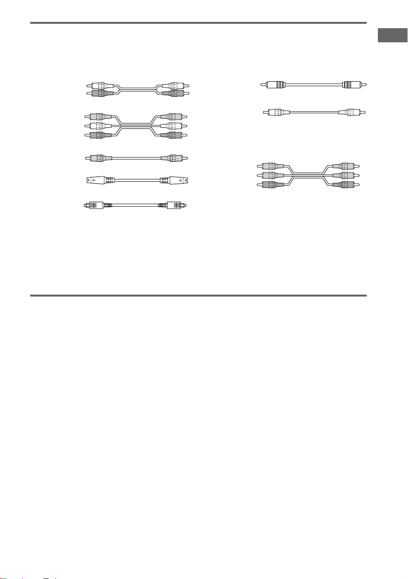
Required cords
The hookup diagrams on the subsequen t p ages assume the use of th e following optional connection
cords (A to H) ( not supplied).
A Audio cord
White (L)
Red (R)
B Audio/video cord
Yellow (video)
White (L/audio)
Red (R/audio)
C Video cord
Yellow
D S-video cord
F Coaxial digital cord
G Monaural audio cord
Black
Tip
Audio cord A can be torn into two monaural audio
cords G.
H Component video cord
Green
Blue
Red
E Optical digital cord
Notes
• Turn off the power to all components before making any connections.
• Be sure to make connections firmly to avoid hum and noise.
• When connecting an audio/video cord, be sure to match the color-coded pins to the appropriate jacks on the
components: yellow (video ) to yel low; white (left, audio) to white; and red (right, audio) to red.
• When connecting optical digital cords, insert the cord plugs straight in until they click into place.
• Do not bend or tie optical digital cords.
If you have Sony components with CONTROL A1II/CONTROL S
jacks
Getting Started
See “CONTROL A1II Control System” on page 49.
GB
7
Page 8
.
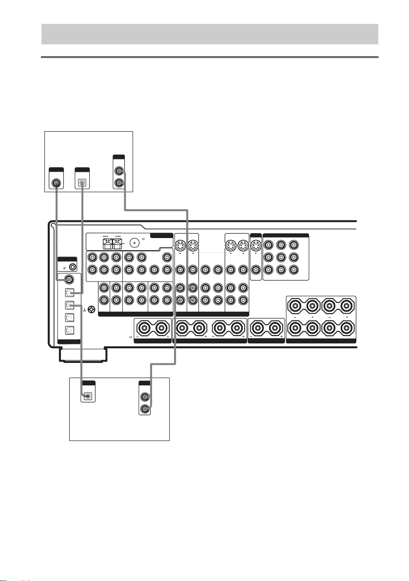
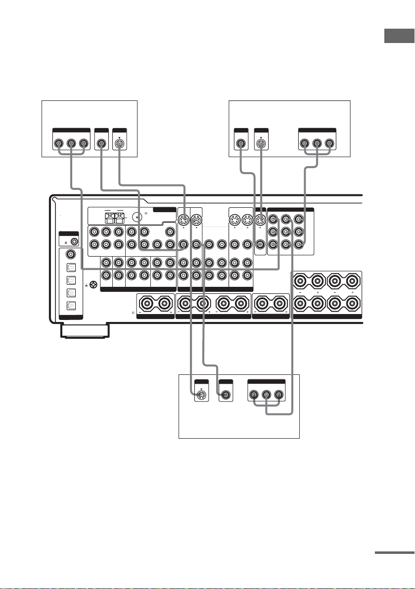
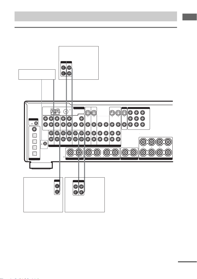
1a: Connecting components with digital audio output jacks
Hooking up a DVD player, TV monitor, or satellite tuner
For details on the required cords (A–H), see page 7.
1 Connect the audio jacks.
DVD player
OUTPUT
AUDIO
OUTPUT
DIGITAL
COAXIAL
F
OUTPUT
DIGITAL
OPTICAL
*
E
OUT
L
R
*
A
MONITOR
COMPONENT VIDEO
S-VIDEO S-VIDEO
VIDEO
TV-SAT DVD MONITOR
OUT
INOUT
VIDEO
IN OUTIN
CENTER SPEAKERSURROUND SPEAKERS FRONT SPEAKERS
Y
B/CB
P
/B-Y
P
R/CR
/R-Y
IR REMOTE
RS232C
RL
A
B
CONTROL
CTRL
A1
COAXIAL
DVD
IN
TV/
SAT
IN
MD/
DAT
IN
MD/
DAT
OUT
OPTICAL
DIGITAL
L
R
DVD
IN
SIGNAL GND
ASSIGNABLE
OUTPUT
DIGITAL
OPTICAL
FM
AM
U
L
CENTER
R
SUB
SURROUND
FRONT
MULTI CH INPUT 2 MULTI CH INPUT 1
L
AUDIO
R
FRONT
WOOFER
OUT
PHONO
CD/SACD
MD/DAT
ANALOG VIDEO
IMPEDANCE
USE 4 - 16
E
ANTENNA
75
COAXIAL
CENTER
LRL
R
SUB
SURR
SURROUND
WOOFER
BACK
IN
OUTINININ
TAPE
SURR BACK SPEAKER
A
OUTPUT
AUDIO
OUT
L
R
IN IN INOUT OUT
S-VIDEO
S-VIDEO
IN IN
VIDEO
IN IN INOUTINOUT
TV/SAT
INOUT
VIDEO
VIDEO
DVD VIDEO 2 VIDEO 1
RL RL
Satellite tuner
* Connect to either the COAXIAL DVD IN or the OPTICAL DVD IN jack. We recommend making connections to
the COAXIAL DVD IN jack.
Note
You can listen to the sound of your TV by connecting your TV’s audio output jacks to the TV/SAT AUDIO IN jacks
on the receiver. In this case, do not connect the TV ’ s vide o output jack to the TV/SAT VID E O IN jack on the
receiver.
GB
8
Page 9
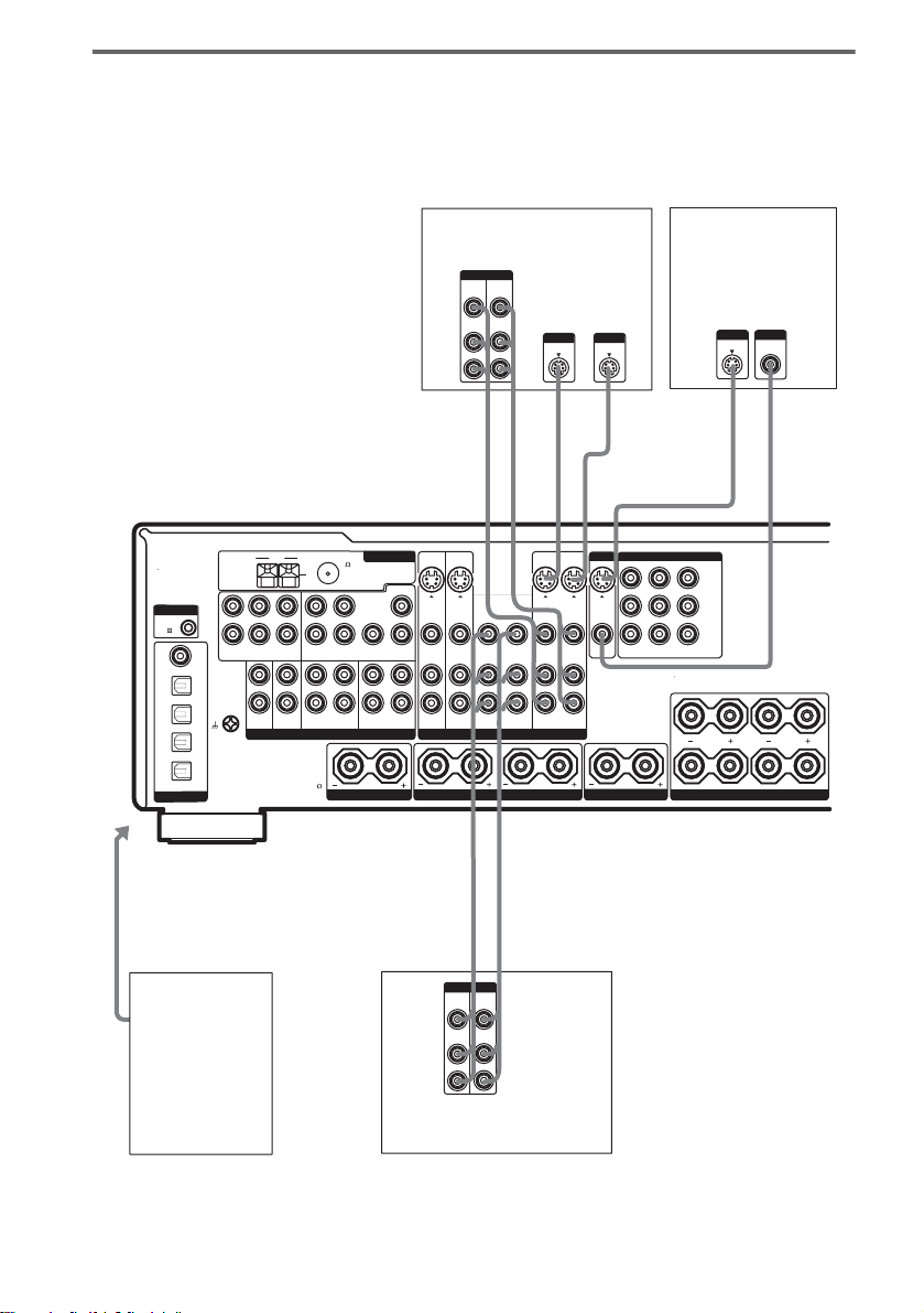
2 Connect the video jacks.
The following illustration shows how to connect a TV or satellite tuner and a DVD player with
COMPONENT VIDEO (Y, P
/B-Y, PR/CR/R-Y) output jacks. Connecting a TV with component
B/CB
video input jacks allo w s you to enjoy higher qualit y vi deo.
Note
On this receiver, standard video signa ls ca n be conve r ted to S-video signals (STR-DA2000ES only).
Getting Started
Satellite tuner
R-Y
OUTPUT
COMPONENT
OUTPUT
OUTPUT
VIDEO S VIDEO
B-Y
Y
HCD DC
ANTENNA
FM
AM
75
U
COAXIAL
CENTER
CONTROL
CTRL
A1
COAXIAL
DVD
IN
TV/
SAT
IN
MD/
DAT
IN
MD/
DAT
OUT
OPTICAL
DIGITAL
L
R
DVD
IN
SIGNAL GND
ASSIGNABLE
L
R
SURROUND
FRONT
MULTI CH INPUT 2 MULTI CH INPUT 1
L
AUDIO
R
PHONO
LRL
CENTER
SUB
WOOFER
CD/SACD
R
SUB
SURR
SURROUND
FRONT
OUT
MD/DAT
ANALOG VIDEO
IMPEDANCE
USE 4 - 16
WOOFER
BACK
INOUTINININ
TAPE
SURR BACK SPEAKER
IN IN INOUT OUT
S-VIDEO S-VIDEO
IN IN
VIDEO
VIDEO
IN IN INOUTINOUT
TV/SAT
DVD VIDEO 2 VIDEO 1
RL RL
OUTPUT
S VIDEO
TV monitor
INPUTINPUT
S VIDEOVIDEO
R-Y
INPUT
COMPONENT
B-Y
Y
H
MONITOR
COMPONENT VIDEO
S-VIDEO
S-VIDEO
VIDEO
INOUT
TV-SAT DVD MONITOR
OUT
IN OUTIN
INOUT
VIDEO
VIDEO
CENTER SPEAKERSURROUND SPEAKERS FRONT SPEAKERS
Y
P
B/CB
/B-Y
P
R/CR
/R-Y
IR REMOTE
RS232C
RL
A
B
HD C
OUTPUT
VIDEO
R-Y
OUTPUT
COMPONENT
B-Y
Y
DVD player
continued
GB
9
Page 10
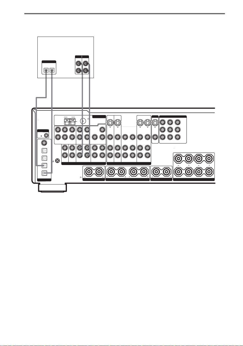
Hooking up an MD/DAT deck
For details on the required cords (A–H), see page 7.
MD/DAT deck
INPUT OUTPUT
LINE
DIGITAL
OPTICAL
OUT
IN
EE AA
l
OUTIN
l
LINE
L
R
l
INOUT
l
AM
L
L
CONTROL
CTRL
A1
R
R
SURROUND
FRONT
DVD
MULTI CH INPUT 2 MULTI CH INPUT 1
IN
COAXIAL
DVD
IN
TV/
SAT
IN
MD/
DAT
IN
MD/
DAT
OUT
DIGITAL
If you want to connect several digital components, but cannot find an
unused input
OPTICAL
SIGNAL GND
ASSIGNABLE
L
AUDIO
R
PHONO
75
U
COAXIAL
CENTER
LRL
CENTER
SUB
WOOFER
CD/SACD
R
SUB
SURR
SURROUND
FRONT
OUT
MD/DAT
ANALOG VIDEO
IMPEDANCE
USE 4 - 16
WOOFER
BACK
INOUTINININ
TAPE
SURR BACK SPEAKER
IN IN INOUT OUT
S-VIDEO S-VIDEO
IN IN
VIDEO
IN IN INOUTINOUT
TV/SAT
INOUT
VIDEO
VIDEO
DVD VIDEO 2 VIDEO 1
RL RL
ANTENNA
FM
MONITOR
COMPONENT VIDEO
S-VIDEO
S-VIDEO
VIDEO
TV-SAT DVD MONITOR
INOUT
OUT
VIDEO
IN OUTIN
CENTER SPEAKERSURROUND SPEAKERS FRONT SPEAKERS
Y
P
B/CB
/B-Y
P
R/CR
/R-Y
IR REMOTE
RS232C
RL
A
B
See “Assigning th e audio input” (pag e 37).
Tips
• All the digital audio jacks ar e compatible with 32 kHz, 44.1 kHz, 48 kHz and 96 kHz sampli ng f requenc ie s.
• You can also connect an LD player with a DOLBY DIGITAL RF OUT jack via an RF demodulator (You cannot
connect an LD player’s DOLBY DIGITAL RF OUT jack directly to this unit’s digital input jacks). Refer to the
operating instructions supplied with the RF demodulator.
Note
You cannot make digital recordings of digital multi channel surround signals.
10
GB
Page 11
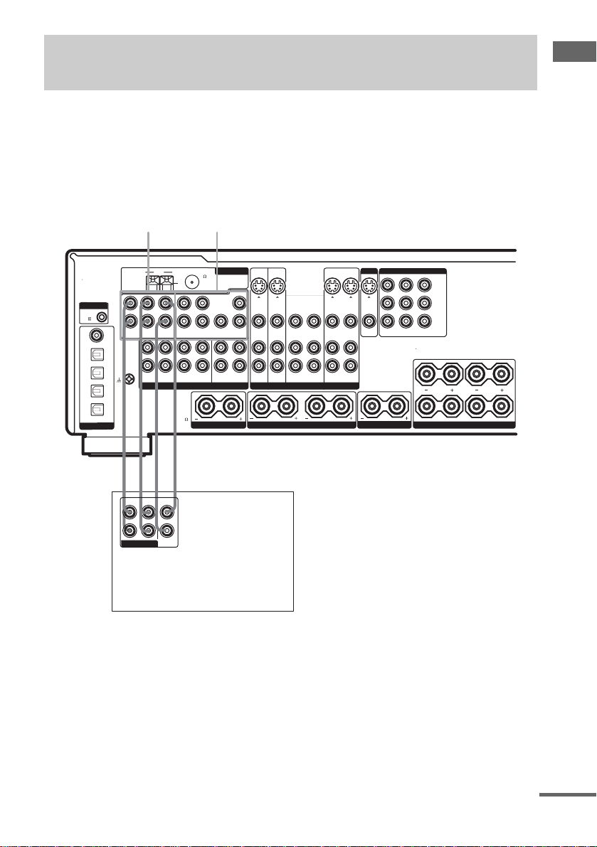
1b: Connecting components with multi channel output jacks
1 Connect the audio jacks.
If your DVD or Super Audio CD playe r is equipped with multi channel output jack s, you can connect
it to this receiver’s MULTI CHANNEL INPUT jacks to enjoy th e multi chan nel sound. Alte rna tively,
the multi channel input jacks can be used to connect an external multi channel decoder.
For detail s on the required cords (A
MULTI
CHANNEL
INPUT 2
–H), see page 7.
MULTI
CHANNEL
INPUT 1
Getting Started
MONITOR
COMPONENT VIDEO
S-VIDEO
S-VIDEO
VIDEO
TV-SAT DVD MONITOR
INOUT
OUT
VIDEO
IN OUTIN
CENTER SPEAKERSURROUND SPEAKERS FRONT SPEAKERS
Y
B/CB
P
/B-Y
P
R/CR
/R-Y
IR REMOTE
RS232C
RL
A
B
CONTROL
CTRL
A1
COAXIAL
DVD
IN
TV/
SAT
IN
MD/
DAT
IN
MD/
DAT
OUT
OPTICAL
DIGITAL
L
R
DVD
IN
SIGNAL GND
ASSIGNABLE
FM
AM
75
U
COAXIAL
L
R
SURROUND
FRONT
MULTI CH INPUT 2 MULTI CH INPUT 1
L
AUDIO
R
PHONO
LRL
CENTER
SUB
SURROUND
FRONT
WOOFER
OUT
CD/SACD
MD/DAT
ANALOG VIDEO
IMPEDANCE
USE 4 - 16
SURR BACK SPEAKER
R
ANTENNA
CENTER
IN IN INOUT OUT
S-VIDEO S-VIDEO
SUB
SURR
IN IN
VIDEO
VIDEO
WOOFER
BACK
IN IN INOUTINOUT
INOUTINININ
TV/SAT
TAPE
DVD VIDEO 2 VIDEO 1
RL RL
INOUT
VIDEO
AA GG
FRONT
SURROUND
MULTI CH OUT
CENTER
SUB
WOOFER
L
R
DVD player,
Super Audi o CD player,
Multi channel decoder, etc.
Tips
• This connection also allows you to enjoy software with multi-channel audio recorded in formats other than the
Dolby Digital, and DTS.
• Make connections to either the MULTI CHANNEL INPUT 1 or MULTI CHANNEL INPUT 2 jacks according to
the number of audio output jacks of the co mponent.
Note
DVD and Super Audio CD players do not have SURR BACK terminals.
continued
11
GB
Page 12
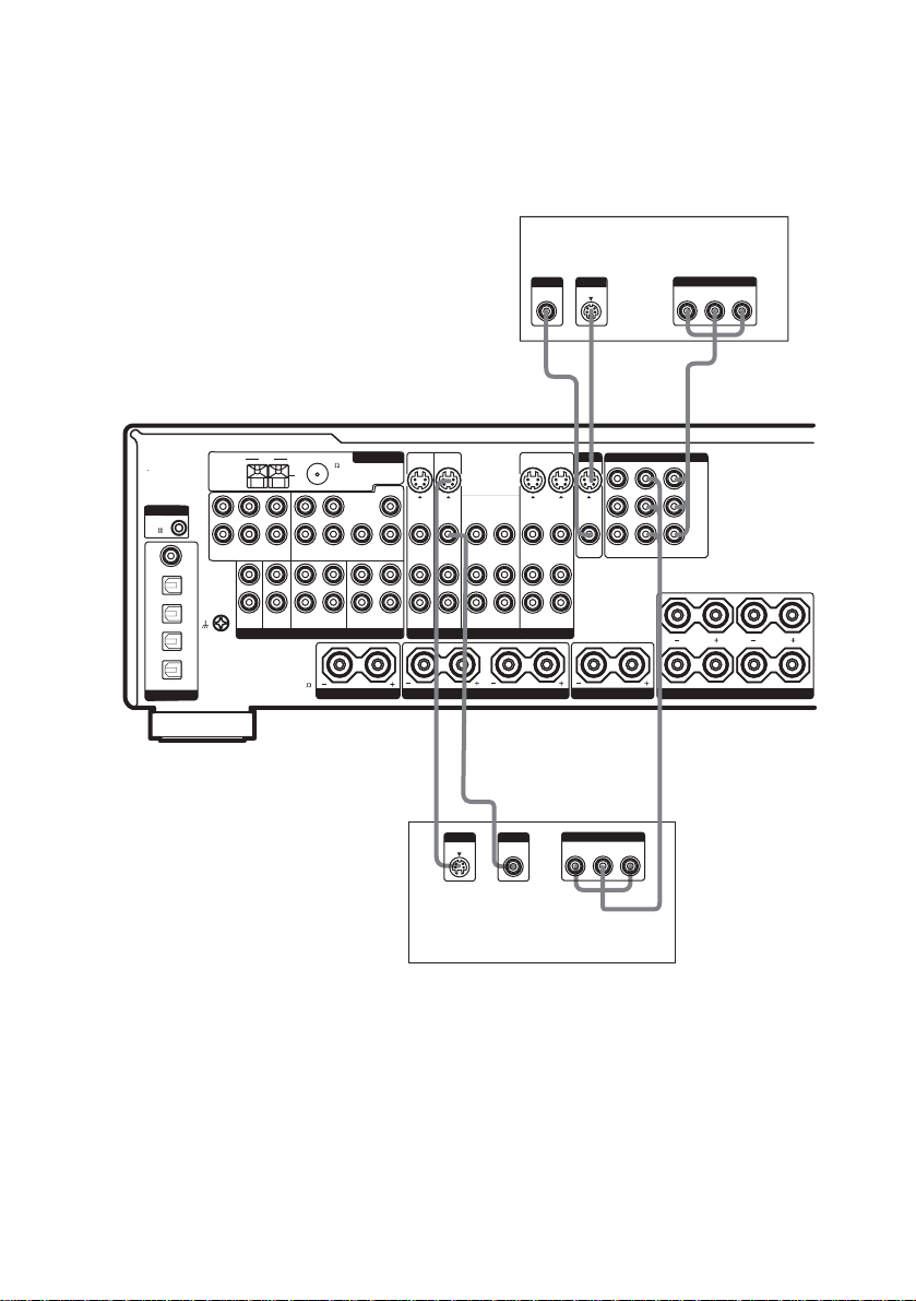
2 Connect the video jacks.
The following illustration shows how to connect a DVD player with COMPONENT VIDEO (Y, PB/
/B-Y, PR/CR/R-Y) output jacks. Connecting a TV with component video inpu t jack s al lows you to
C
B
enjoy higher quality video.
Note
On this receiver, standard video sign als can be con v e rted to S-vi deo signa ls (STR-DA2000ES only).
TV monitor
CONTROL
CTRL
A1
COAXIAL
DVD
IN
TV/
SAT
IN
MD/
DAT
IN
MD/
DAT
OUT
OPTICAL
DIGITAL
L
R
DVD
IN
SIGNAL GND
ASSIGNABLE
FM
AM
L
R
SURROUND
FRONT
MULTI CH INPUT 2 MULTI CH INPUT 1
L
AUDIO
R
PHONO
75
U
COAXIAL
LRL
CENTER
SUB
SURROUND
FRONT
WOOFER
OUT
CD/SACD
MD/DAT
ANALOG VIDEO
IMPEDANCE
USE 4 - 16
SURR BACK SPEAKER
R
ANTENNA
CENTER
IN IN INOUT OUT
S-VIDEO S-VIDEO
SUB
SURR
IN IN
VIDEO
VIDEO
WOOFER
BACK
IN IN INOUTINOUT
INOUTINININ
TV/SAT
TAPE
DVD VIDEO 2 VIDEO 1
RL RL
OUTPUT
S VIDEO
INPUT
INPUT
S VIDEOVIDEO
DC
MONITOR
COMPONENT VIDEO
S-VIDEO
S-VIDEO
VIDEO
INOUT
VIDEO
VIDEO
TV-SAT DVD MONITOR
INOUT
OUT
IN OUTIN
CENTER SPEAKERSURROUND SPEAKERS FRONT SPEAKERS
INPUT
COMPONENT
B-Y
Y
R-Y
H
Y
P
B/CB
/B-Y
R/CR
P
/R-Y
IR REMOTE
RS232C
RL
A
B
HD C
OUTPUT
VIDEO
R-Y
OUTPUT
COMPONENT
B-Y
Y
12
DVD player
GB
Page 13
1c: Connecting components with only analog audio jacks
Hooking up audio components
For detail s on the required cords (A–H), see page 7.
MD/DAT deck
INPUT OUTPUT
LINE
LINE
L
l
R
AAA
l
INOUT
Turntable
Getting Started
AM
L
L
CONTROL
CTRL
A1
R
R
SURROUND
FRONT
DVD
MULTI CH INPUT 2 MULTI CH INPUT 1
IN
COAXIAL
DVD
IN
TV/
SAT
IN
MD/
DAT
IN
MD/
DAT
OUT
DIGITAL
OPTICAL
SIGNAL GND
ASSIGNABLE
L
AUDIO
R
PHONO
CD/SACD
A
OUTPUT
CD/Super Audio CD
player
ANTENNA
FM
75
U
COAXIAL
CENTER
LRL
CENTER
SUB
SURROUND
FRONT
WOOFER
OUT
MD/DAT
ANALOG VIDEO
IMPEDANCE
USE 4 - 16
SURR BACK SPEAKER
S-VIDEO S-VIDEO
R
SUB
SURR
VIDEO
WOOFER
BACK
INOUTINININ
TV/SAT
TAPE
l
l
AA
LINE
INPUT OUTPUT
LINE
LINE
L
R
L
R
Tape deck
IN IN INOUT OUT
IN IN
IN IN INOUTINOUT
INOUT
VIDEO
VIDEO
DVD VIDEO 2 VIDEO 1
RL RL
INOUT
MONITOR
S-VIDEO
S-VIDEO
VIDEO
OUT
INOUT
VIDEO
CENTER SPEAKERSURROUND SPEAKERS FRONT SPEAKERS
Note
If your turntable has a ground wire, conn ect it to the U SIGNAL GND terminal.
COMPONENT VIDEO
TV-SAT DVD MONITOR
IN OUTIN
Y
B/CB
P
/B-Y
R/CR
P
/R-Y
IR REMOTE
RS232C
RL
A
B
continued
13
GB
Page 14
Hooking up video components
If you connect your T V to the MONITOR jacks, you can watch the video from the selected input
(page 24). You can also display the SP. SET UP, LEVEL, EQUALIZER, CUSTOMIZE and TUNER
menu settings and sound fields on your TV by pressing ON SCREEN on the re m ot e.
For details on the required cords (A
–H), see page 7.
CONTROL
CTRL
A1
DVD
IN
COAXIAL
DVD
IN
TV/
SAT
IN
MD/
DAT
IN
MD/
DAT
OUT
OPTICAL
DIGITAL
To the
VIDEO 3
INPUT jacks
(Front panel)
B
, D
Camcorder or
TV game
FM
AM
U
L
L
R
SIGNAL GND
ASSIGNABLE
CENTER
R
SUB
SURROUND
FRONT
MULTI CH INPUT 2 MULTI CH INPUT 1
L
AUDIO
R
FRONT
WOOFER
OUT
PHONO
CD/SACD
MD/DAT
ANALOG VIDEO
IMPEDANCE
USE 4 - 16
ANTENNA
75
COAXIAL
CENTER
LRL
R
SUB
SURR
SURROUND
WOOFER
BACK
INOUTINININ
TAPE
SURR BACK SPEAKER
VCR
OUTPUTINPUT
VIDEO
VIDEO
OUT
IN
AUDIO
AUDIO
OUT
IN
BB
L
L
R
L
INPUT
S VIDEO
D D
INOUT
L
OUTPUT
S VIDEO
INOUT
TV monitor
INPUT
INPUT
S VIDEO
VIDEO
DC
L
MONITOR
COMPONENT VIDEO
IN IN INOUT OUT
S-VIDEO S-VIDEO
IN IN
VIDEO
IN IN INOUTINOUT
TV/SAT
INOUT
VIDEO
VIDEO
DVD VIDEO 2 VIDEO 1
RL RL
S-VIDEO
S-VIDEO
VIDEO
TV-SAT DVD MONITOR
OUT
INOUT
VIDEO
IN OUTIN
CENTER SPEAKERSURROUND SPEAKERS FRONT SPEAKERS
Y
B/CB
P
/B-Y
P
R/CR
/R-Y
IR REMOTE
RS232C
RL
A
B
L
INOUT
L
B
B
OUTPUTINPUT
VIDEO
VIDEO
IN
OUT
AUDIO
AUDIO
OUT
IN
L
R
VCR
14
GB
Page 15
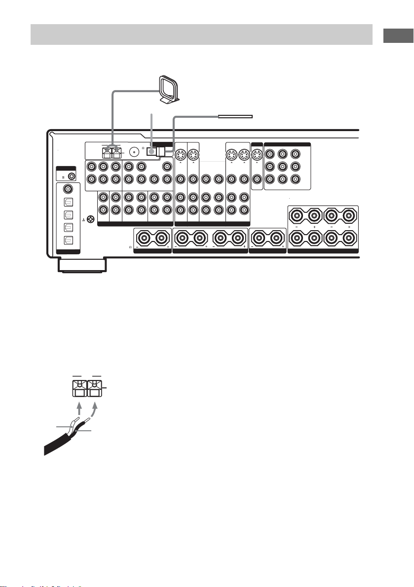
2: Connecting the antennas
A
B
Connect the supplied AM loop antenna and FM wire antenna.
AM loop antenna
(supplied)
Getting Started
FM wire antenna
(supplied)
MONITOR
COMPONENT VIDEO
S-VIDEO
S-VIDEO
VIDEO
TV-SAT DVD MONITOR
INOUT
OUT
VIDEO
IN OUTIN
CENTER SPEAKERSURROUND SPEAKERS FRONT SPEAKERS
Y
B/CB
P
/B-Y
P
R/CR
/R-Y
IR REMOTE
RS232C
RL
A
B
CONTROL
CTRL
A1
COAXIAL
DVD
IN
TV/
SAT
IN
MD/
DAT
IN
MD/
DAT
OUT
OPTICAL
DIGITAL
L
R
DVD
IN
SIGNAL GND
ASSIGNABLE
FM
AM
L
R
SURROUND
FRONT
MULTI CH INPUT 2 MULTI CH INPUT 1
L
AUDIO
R
PHONO
75
U
COAXIAL
LRL
CENTER
SUB
SURROUND
FRONT
WOOFER
OUT
CD/SACD
MD/DAT
ANALOG VIDEO
IMPEDANCE
USE 4 - 16
SURR BACK SPEAKER
R
SURR
BACK
*
ANTENNA
CENTER
IN IN INOUT OUT
S-VIDEO S-VIDEO
SUB
IN IN
VIDEO
VIDEO
WOOFER
IN IN INOUTINOUT
INOUTINININ
TV/SAT
TAPE
DVD VIDEO 2 VIDEO 1
RL RL
INOUT
VIDEO
* The shape of the connector varies dep end ing on the area code.
Notes
• To prevent noise pickup, keep the AM loop antenna away from the receiver and other components.
• Be sure to fully extend the FM wire an ten n a.
• After connecting the FM wire ante nna, keep it as horizontal as possible .
• Do not use the U SIGNAL GND terminal for grounding the receiver.
• When you connect supplied AM antenna to the component, connect the black cord (B) to U jack, and the white
cord (A) to the other jack.
AM
U
15
GB
Page 16
3: Connecting speakers
Connect your speakers to the receiver. This receiver allows you to use a 7.1 channel system (STRDA2000ES) or 6.1 channel (STR-DB2000).
To fully enjoy theater-like multi channel surround sound requi res five speakers (two front spe aker s, a
center speake r, and two surround spea kers) and a sub woofer (5.1 channel).
You can enjoy high fidelity reproduction of DVD software recorded in the Surround EX format if you
connect one addit ional surround back s peaker (6.1 channel) or t w o surround back speakers (7.1
channel, STR-DA2000ES only) (see “Selecting the surround back decoding mode” on page 35).
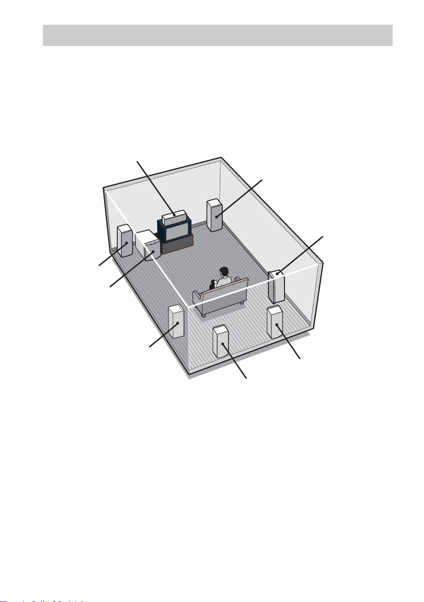
Example of 7.1 channel speaker system configuration
Center speaker
Front speaker (R)
Surround speaker (R)
Front speaker (L)
Sub woofer
16
Surround speaker (L)
Surround back speaker (L)
Tips
• When you connect 6.1 channel speaker system, place the surround back speaker behind the listening position.
• Since the sub woofer does not emit highly directional signals, you can place it where ve r you want.
GB
Surround back speaker (R)
Page 17
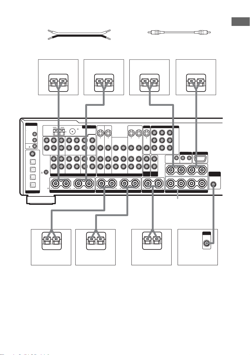
Required cords
A Speaker cords (not supplied)
(+)
(–)
STR-DA2000ES
B Monaural audio cord (not supplied)
Black
Getting Started
CONTROL
CONTROL S
OUT
IN
CTRL
A1
COAXIAL
DVD
IN
TV/
SAT
IN
MD/
DAT
IN
MD/
DAT
OUT
OPTICAL
DIGITAL
E
L
R
DVD
IN
SIGNAL GND
IMPEDANCE
USE 4 - 16
ASSIGNABLE
Surround back
speaker (R)*
Ee
A
FM
AM
L
R
SURROUND
FRONT
MULTI CH INPUT 2 MULTI CH INPUT 1
L
AUDIO
R
PHONO
75
U
COAXIAL
LRL
CENTER
SUB
SURROUND
FRONT
WOOFER
OUT
CD/SACD
MD/DAT
ANALOG VIDEO
R
SURROUND BACK SPEAKERS
Surround back
speaker (L)*
Ee
ANTENNA
CENTER
IN IN INOUT OUT
S-VIDEO S-VIDEO
R
SUB
SURR
IN IN
VIDEO
WOOFER
BACK
IN IN INOUT FRONTOUTINOUT
INOUTINININ
TV/SAT
TAPE
A
VIDEO
DVD
RLL RL
Front speaker (R)
S-VIDEO S-VIDEO
INOUT
OUT
VIDEO
VIDEO
VIDEO 2 VIDEO 1
Front speaker (L)
Ee
E
A
MONITOR
COMPONENT VIDEO
Y
P
B/CB
VIDEO
TV-SAT DVD MONITOR
OUT
IN
IN OUTIN
2ND
PRE OUT
ZONE
CENTER SPEAKERSURROUND SPEAKERS FRONT SPEAKERS
/B-Y
PR/C
/R-Y
R
R
IR REMOTE
OUTTRIGGER OUT IN
e
A
RS232C
SUB
L
A
B
WOOFER
AUDIO
OUT
FRONT
SPEAKERS B**
AAB
e
E
A
e
E
e
INPUT
AUDIO
IN
Surround speaker
(R)
Surround speaker
(L)
Center speaker
Sub woofer
* If you connect only one surround back speaker, connect it to the SURROUND BACK SPEAKERS L terminal.
**You can select the front speakers you want to use with SPEAKERS. For details, see “Selecting the speaker system”
(page 46).
Tip
To connect certain spea kers to another pow er amplifier, use t he PRE OUT jacks. The same signal is output from both
the SPEAKERS jacks and the PRE OUT jacks (front speakers only).
17
GB
Page 18
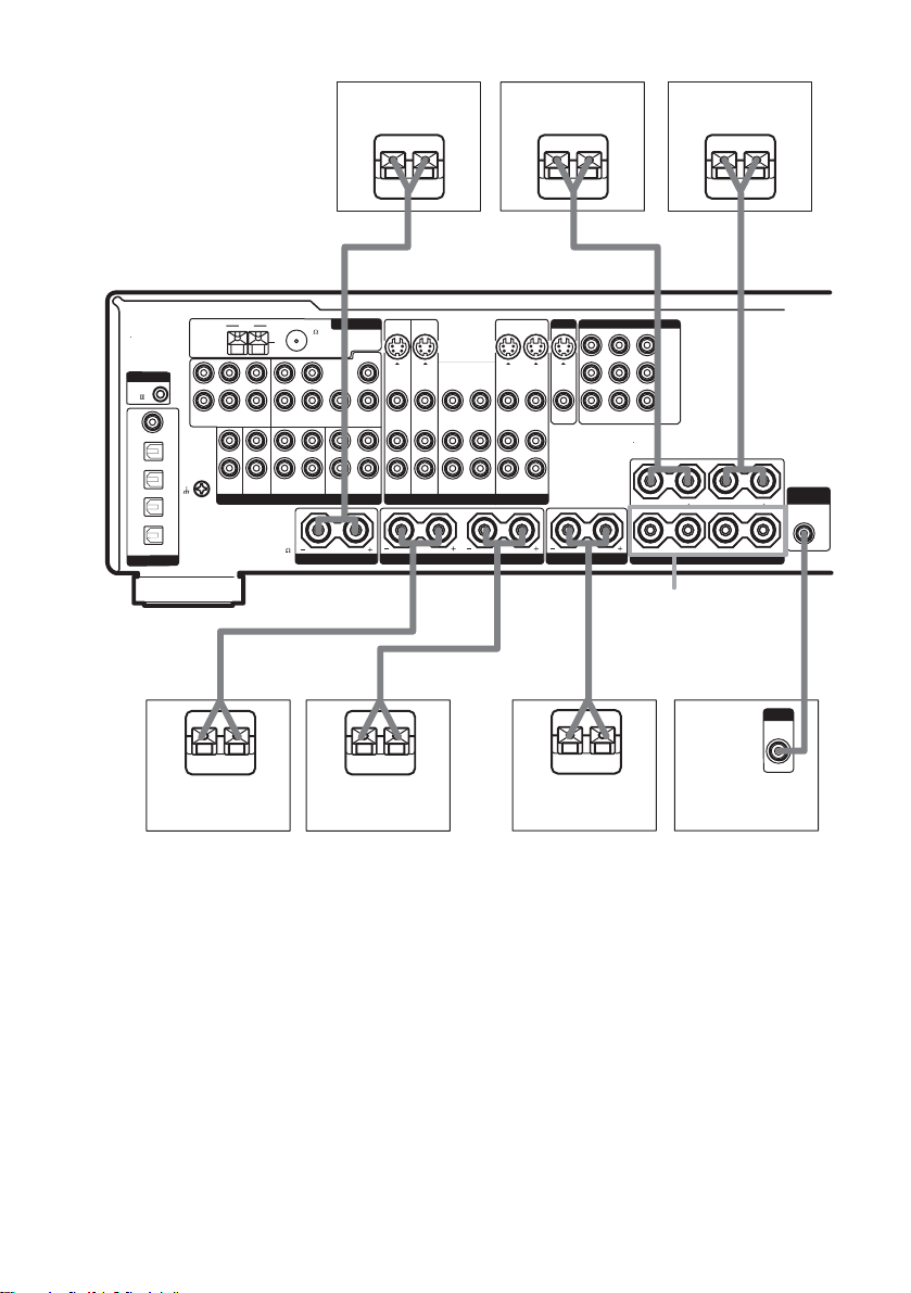
STR-DB2000
CONTROL
CTRL
A1
COAXIAL
DVD
IN
TV/
SAT
IN
MD/
DAT
IN
MD/
DAT
OUT
OPTICAL
DIGITAL
E
L
R
DVD
IN
SIGNAL GND
ASSIGNABLE
INOUT
VIDEO
Front speaker (R)
Ee
A
MONITOR
COMPONENT VIDEO
S-VIDEO
S-VIDEO
VIDEO
TV-SAT DVD MONITOR
OUT
INOUT
VIDEO
IN OUTIN
CENTER SPEAKERSURROUND SPEAKERS FRONT SPEAKERS
Front speaker (L)
E
A
Y
B/CB
P
/B-Y
R/CR
P
/R-Y
IR REMOTE
RS232C
RL
A
B
WOOFER
e
SUB
AUDIO
OUT
FM
AM
75
U
L
R
SURROUND
FRONT
MULTI CH INPUT 2 MULTI CH INPUT 1
L
AUDIO
R
PHONO
COAXIAL
LRL
CENTER
SUB
SURROUND
FRONT
WOOFER
OUT
CD/SACD
MD/DAT
ANALOG VIDEO
IMPEDANCE
USE 4 - 16
SURR BACK SPEAKER
Surround back
speaker
Ee
ANTENNA
CENTER
IN IN INOUT OUT
S-VIDEO S-VIDEO
R
SUB
SURR
IN IN
VIDEO
WOOFER
BACK
IN IN INOUTINOUT
INOUTINININ
TV/SAT
TAPE
A
VIDEO
DVD VIDEO 2 VIDEO 1
RL RL
FRONT
SPEAKERS B**
AAB
e
E
A
e
E
e
INPUT
AUDIO
IN
18
Surround speaker
(R)
Surround speaker
(L)
Center speaker
Sub woofer
* You can select the fr ont speakers y ou want to use with SPEAKERS. Fo r details, see “Selectin g the speake r system”
(page 46).
GB
Page 19

4: Connecting the AC
S
power cord
Connect the AC power cord to a wall outlet.
SUB
L
WOOFER
AUDIO
OUT
L
PEAKERS
• All settings in th e SP. SET UP, LEVEL,
EQUALIZER, CUSTOMIZE, TUNER
and CIS (models of ar ea code U, CA
only) menus.
• The sound field memor ized for each
input and pres et station.
• All preset stations.
• All index names for inputs and preset
stations.
Note
If “2nd zone on” appears in the display, the initial setup
operation cannot be performed. Turn off the indication
by following the first tip of “Listening to the sound in
another zone” (page 48).
Getting Started
AC power
cord
To a wall outlet
b
Performing initial setup
operations
Before using the receiver for the first time,
initialize the receiver by performing the
following procedure.
This procedure can a ls o be used to return
settings you have made to t h eir factory d efaults.
1 Press ?/1 on the receiver to turn off the
receiver.
2 Hold down ?/1 on the receiver for 5
seconds.
3 While “ENTER to Clear” appears in the
display, press MEMORY/ENTER on the
receiver.
After “MEMORY CLEARING” appears in
the display for a while, “MEMORY
CLEARED!” appears.
The following are reset to their factory
settings.
19
GB
Page 20

5: Setting up the speakers
You can use the SP. SET UP menu to set the size
and distance of the speakers connected t o this
system.
1 Press ?/1 to turn on the system.
2 Press MAIN ME NU to select “SP. SET
UP”.
3 Rotate MENU to select the menu item
you want.
For more information, see “Speaker setup
parameters”.
Notes
• Certain setup parameters may be dimmed in the
display. This means that the selected parameter
is either unavailale or fixed and unchangeable
due to sound field (pages 33–34) or other
settings.
• Some speaker setup items may a ppe a r dim m ed
in the display. This means that they have been
adjusted automati cally due to other speaker
settings. Depending on the settings, you may or
may not be able to adjust certa in sp eakers.
4 Rotate –/+ to select the parameter.
5 Repeat steps 3 and 4 until you have set
all of the items that follow.
Speaker setup parameters
The initial settings are underlined.
x EASY SET UP (Speaker easy setup)
• YES
You can set up your speakers automatically
by selectin g a pre-defined sp eaker pattern (see
the supplied “Easy Setup Guide”).
•NO
Select to adjust the settings of each speaker
manually.
x SP PATTER N
(Speaker setup pattern)
When “EASY SET UP” is set to “YES”, select
the speaker setup pattern. Rot ate –/+ to select the
speaker setup pattern and press MEMORY/
ENTER to enter the selection. Check your
speaker pattern using the supplied “Easy Setup
Guide”.
x SUB WOOFER (Sub woofer)
•YES
If you connect a sub woofer, select “YES”.
•NO
If you did not connect a sub woofer, select
“NO”. This activates the bass redirection
circuitry and outputs the LFE signals from
other speakers.
x FRONT SP (Front speakers)
• LARGE
If you connect large speakers that will
effectively reproduce bass frequencies, select
“LARGE”. Normally, select “LARGE”.
When the sub woofer is set to “NO”, front
speakers are automatically set to “LARGE”.
•SMALL
If the sound is distorted, or you feel a lack of
surround effects w hen using multi channel
surround sound, se le ct “SM ALL” to activate
the bass redirection circuitry and outp ut the
front channel ba ss frequencies from t he sub
woofer. When the front speakers are set to
“SMALL”, the center, surround and surround
back speakers are also automatically set to
“SMALL” (unle ss previously set to “NO”).
x CTR SP (Center speaker)
• LARGE
If you connect a large speaker that will
effectively reproduce bass frequencies, select
“LARGE”. Normally, select “LARGE”.
However, if the front speakers ar e set to
“SMALL”, you cannot set the center speaker
to “LARGE”.
•SMALL
If the sound is distorted, or you feel a lack of
surround effects w hen using multi channel
surround sound, se le ct “SM ALL” to activate
the bass redirection circuitry and outp ut the
center channel bass frequencies from the front
speakers (if set to “LARGE”) or sub woofer.
•NO
If you did not co nne ct a cent er spea ker , sel ect
“NO”. The sound of the center channel will be
output from the front speakers.
When the multi channel input is selected,
analog downmixing is performed.
20
GB
Page 21

x SURR SP
(Surround speakers)
The surround back speakers are set to the same
setting.
• LARGE
If you connect large speakers that will
effectively reproduce bass frequencies, select
“LARGE”. Normally, select “LARGE”.
However, if the front speakers are set to
“SMALL”, you cannot set the surround
speakers to “LARGE”.
•SMALL
If the sound is distorted, or you feel a lack of
surround effects when using multi channel
surround sound, select “SMALL” to activ at e
the bass redire ction circuitry and output the
surround chan nel bass frequencie s from the
sub woofer or ot her “LARGE” speak ers.
•NO
If you did not connect surround speakers,
select “NO”.
x SB SP
(Surround back speakers)
When the surr ound speak ers are set to “NO”, th e
surround back speakers are also au t omatically
set to “NO” and the setting cannot be ch anged.
STR-DA2000ES
• DUAL
If you connect two su rround back speak ers,
select “DUAL”. The sound will be output to a
maximum of 7.1 channels.
•SINGLE
If you connect only one surround ba ck
speaker, select “SINGLE”. The sound will be
output to a maximum of 6.1 channels.
•NO
If you did not connect surround back
speakers, select “NO”.
STR-DB2000
•YES
If you connect a surr ound back speake r, select
“YES”.
•NO
If you did not connect surround back speaker,
select “NO”.
Tip
The “LARGE” and “SMALL” settings for each
speaker determine whether or not the inte r na l sound
processor will cut the bass signal from that channel.
When the bass is cut from a channel, the bass
redirection circuitry se nds the co rre sponding bass
frequencies to the sub woofer or other “LARGE”
speakers.
However, it best not to cut them, if poss ible. Therefore,
even when using small speakers, you c an set them to
“LARGE” if you want to output the bass frequencies
from that speaker. On the other hand, if you are using
a large speaker, but prefer not to have bass frequencies
output from that spea k e r, se t it to “SMALL”.
If the overall sound level is lower than you prefer, set
all speakers to “LARGE”. If there is not enough bass,
you can use the equalizer to boost th e bass levels. To
adjust the equalizer, see page 40.
x FRONT X.X meter*
(Front speaker distance)
Initial setting: 3.0 met er (10 feet)
Lets you set the distance from your listening position
to the front speakers (A). You can adjust from 1.0
meter to 7.0 meters (3 to 23 feet) in 0. 1 meter (1 foot)
steps.
If both front speakers are n ot p lac ed an eq ua l d i st an ce
from your listening position, set the distance to the
closest speaker.
When placing only one surround bac k spe a ke r
A A
30˚30˚
100˚-120˚100˚-120˚
Getting Started
continued
21
GB
Page 22

When placing two surround back speak ers
(The angle B should be the same)
AA
30˚30˚
100˚-120˚100˚-120˚
B
B
B
x CTR X.X meter*
(Center speaker distance)
Initial setting: 3.0 met er ( 10 feet)
Lets you set the distance from your listening position
to the center speak er. You can adjust fro m 1.0 me ter to
7.0 meters (3 to 23 feet) in 0.1 meter (1 foot) steps.
x SURR X.X meter*
(Surround speaker distance)
Initial setting: 3.0 met er ( 10 feet)
Lets you set the distance from your listening position
to the surround speakers. You can adjust from 1.0
meter to 7.0 meters (3 to 23 feet) in 0.1 meter (1 foot)
steps.
If both surround speakers are not placed an equal
distance from your listening position, set the distance
to the closest speaker.
x SB X.X meter*
(Surround back speaker distance)
Initial setting: 3.0 met er ( 10 feet)
Lets you set the distance from your listening position
to the surround back speaker. You can adju st from 1.0
meter to 7.0 meters (3 to 23 feet) in 0.1 meter (1 foot)
steps.
If you connect two surround back speakers and both
surround back speakers are not place d an equa l
distance from your listening position (STRDA2000ES only), set the distance to the c lose st
speaker.
Tip
The receiver lets you to input the speaker position in
terms of distance. However, it is not possible to set the
center speaker further tha n the front speakers. Also , the
center speaker cannot be set more tha t 1. 5 me ters (5
feet) closer than the front speakers.
Likewise, the surround speakers can not be set farthe r
away from the listening position than the front
speakers. And they ca n be no more t han 4.5 m eters (15
feet) closer.
This is because incorrect speak er pla c em e nt is not
conducive to the enjoyment of surr ound sound.
Please note that, setting the speaker distance closer
than the actual location of the speakers will cause a
delay in the output of the sound from that spe ak er. In
other words, the speaker will sound like it is fa rthe r
away.
For example, setting the cen ter speaker distance 1–2
meters (3–6 feet) closer than the ac tual speaker
position will create a fairly realistic sensation of being
“inside” the screen. If you cannot obtain a satisfactory
surround effect because the sur ro und speak ers are too
close, setting the surround speaker distance closer
(shorter) than the actual dist an ce wil l create a larger
sound stage.
Adjusting these parameter while listening to the sound
often results in much better surr ound sound. Give it a
try!
For advanced speaker setups
Use the CUSTOMIZE menu and set “MENU
EXP.” to “ON”. This enables advanced setups
including those o f th e heights of the surround
speakers.
For details on “MENU EXP.”, see page 40. For
details on how to set the i tems, see page 41.
22
* For models of area code U, CA, “X feet” is
displayed.
GB
Page 23

6: Adjusting the speaker levels and balance
— TEST TONE
Adjust the speaker levels and balance while
listening the test tone from your listening
position. Use the remote for the operation.
For details on the remote operation, refer to the
operating instructions supplied with the remote.
Tip
The receiver employs a test tone with a frequency
centered at 800 Hz.
1 Press ?/1 on the remote to turn on the
receiver.
2 Press TEST TONE on the remote.
“TEST TONE” in the LEVEL menu
appears in the display and the test tone is
output from each speaker in sequence.
3 Adjust the speaker level and balance
using the LEVEL menu so that the level
of the test tone sounds the same from
each speaker.
For details on the LEVEL menu settings,
see page 3 8.
Tips
• To adjust the level of all spea ke r s a t the same
time, press MASTER VOL +/– on the remote or
turn MASTER VO LU ME –/+ on the receiver .
• You can also use –/+ on the receiver for the
adjustment.
4 Press TEST TONE again.
The test tone turns off.
To output the test tone only from
a specific speaker
Set “TEST TONE” in the LEVEL menu to
“FIX” (page 3 8) . Th e t est tone is output only
from the selected speaker.
For more precise adjustment
You can output the test tone or sound source
from two adjacent speakers to adjust their
balance and level.
Set “MENU EXP.” in the CUSTOMIZE menu
to “ON” (page 40). Then select the two speakers
you want to adjust using “PHASE NOISE” or
“PHASE AUDIO” in the LEVEL menu
(page 43).
Getting Started
23
GB
Page 24

Amplifier Operation
Selecting the component
1 Rotate INPUT SELECTOR to select the
input.
The selected inpu t appears in the display .
To select the Display
VCR VIDEO 1 or VIDEO
Camcorder or TV game VIDEO 3
DVD player DVD
Satellite tuner TV/SAT
MD or DAT deck MD/DAT
CD or Super Audio CD
player
Tape deck TAPE
Built-in tuner (FM) Tuner (FM)
Built-in tuner (AM) Tuner (AM)
Turntable PHONO
2
CD/SACD
2 Turn on the component and start
playback.
3 Rotate MASTER VOLUME –/+ to adjust
the volume.
To mute the sound
Press MUTING on the remote. To cancel, press
MUTING on the remote again or turn MASTER
VOLUME –/+ clockwise to raise the volume.
Even if you turn off the receiver, the muting
function works when you turn on the receiver
again.
Notes on using headphones
• When headphones are connected, you can select only
the following sound fields (page 34).
– HEADPHONE (2CH)
– HEADPHONE (DIRECT)
– HEADPHONE (MULTI 1)
– HEADPHONE (MULTI 2)
– HEADPHONE THEATER
• When headphones are connected and you use the
MULTI CH DIRECT function (page 25), the sound
of all channels may not output depending on the
speaker settings.
24
GB
Page 25

Listening to multi channel
Listening to FM/AM radio
sound
— MULTI CH IN
You can select the audio directly from the
components connected to the MULTI
CHANNEL INPUT jacks. This enables you to
enjoy high quality analog inputs like DVD or
Super Audio CD.
Surround effects are not activated when using
this input.
STR-DA2000ES
Move the easy scroll key on the remote to
select “MULTI”, then press the key to enter
the selection.
STR-DB2000
Press MULTI CH on the remote.
The selected audio source is output.
When a center speaker or sub
woofer is not connected
If you have set the center speaker to “NO”, or set
the sub woofer to “NO” in the SP. S ET UP menu
(page 20), and you ac t i vate the MULTI CH IN
function, the analog center or sub woofer audio
will be output from the front left and right
speakers.
You can listen to FM and AM broadcasts
through the built-in tuner. Before operation,
make sure you have connected the FM and AM
antennas to th e receiver (see page 15).
Tip
The tuning scale for direct tuning differs depending on
the area code as shown in the follo wing ta bl e. Fo r
details on area codes, see page 3.
Area code FM AM
U, CA 100 kHz 10 kHz*
CEL, SP 50 kHz 9 kHz
* The AM tuning scale can be changed (see page 56 ).
Automatic tuning
1 Rotate INPUT SELECTOR to select
“FM” or “AM”.
2 Press TUNING + or TUNING –.
Press TUNING + to scan from low to high;
press TUNING – to scan from high to low.
The receiver stops scanning whenever a
station is received.
In case of poor FM stereo
reception
If the FM stereo reception is poor and
“STEREO” flashes in the display, select
monaural audio so that the sound will be less
distorted.
1 Press MA IN MEN U to sele ct “TUNER”.
2 Rotate MENU to select “FM MODE”.
3 Rotate –/+ to select “MONO”.
The FM reception switches to monaural.
Amplifier Operation
continued
25
GB
Page 26

Direct tuning
Enter a frequency of the station directly by using
the numeric buttons on the remote.
For details on the supplied remote, refer to the
operating instructions supplied with the remote.
1 STR-D A 2000ES:
Move the easy scroll key to select
“TUNER”, then press the key
repeatedly to select “FM” or “AM”.
STR-DB2000:
Press TUNER on the remote repeatedly
to select FM or AM.
You can also use INPUT SELECTOR on
the receiver.
2 Press ALT, then press D.TUNING on
the remote.
3 Press the numeric buttons to enter the
frequency.
Example 1: FM 102.50 MHz
Press 1 b 0 b 2 b 5 b 0
Example 2: AM 1,350 kHz
Press 1 b 3 b 5 b 0
(You do not have to enter the last “0” when
the tuning scale is set to 10 kHz.)
If you have tuned in a n AM station, adjust
the direction of the A M loop antenna for
optimum reception.
If you cannot tune in a station
and the entered numbers flash
Make sure you have entered the right frequency.
If not, repeat step 3. If th e e nt er ed numbers still
flash, the frequency is not used in your area.
Storing FM stations automatically
— AUTOBETICAL
(Models of area code CEL only)
This function lets you store up to 30 FM and FM
RDS stations i n alphabetical order without
redundancy. Additionally, it only stores the
stations with the clearest sign al s.
If you want to store FM or AM stations one by
one, see “Presetting radio stations”.
1 Press ?/1 to turn off the receiver.
2 Hold down MEMORY/ENTER and press
?/1 to turn the receiver back on.
“Autobetical” appears in the display and the
receiver scans and stores all the FM and FM
RDS stations in the broadcast area.
For RDS stations, the tuner fir st c he c ks fo r
stations broadc as ti ng the same program ,
then stores only the one with the clearest
signal. The selected RDS stations are sorted
alphabetically by their Program Service
name, then assigned a 2-character preset
code. For more details on RDS, see
page 28.
Regular FM stations are assigned 2character preset codes and stored afte r t he
RDS station.
When done, “Finis he d” appears in the
display momentarily and the receiver
returns to the normal operat ion.
Notes
• Do not press any button on the receiver or supplied
remote during autobetical opera tion, except ?/1.
• If you move to another area, repeat this procedure to
store stations in your new area.
• For details on tuning the stored stations, see “Tuning
to preset stations”.
• If you move the antenna after stori ng sta ti ons with
this procedure, the stored settings may no longer be
valid. If this happens, repeat this procedure to store
the stations again.
26
GB
Page 27

Presetting radio stations
You can preset up to 30 FM or AM stations.
Then you can easily tu ne in the stations you
often listen to.
Presetting radio stations
1 Rotate INPUT SELECTOR to select
“FM” or “AM”.
2 Tune in the station that you want to
preset using Automatic Tuning
(page 25) or Direct Tuning (page 26).
Switch the FM reception mo de if necessa ry
(page 25).
3 Press MEMORY/ ENTE R .
“MEMORY” appe ars in the display for a
few seconds. Do steps 4 to 5 before the
display goes out.
4 Press PRESET TU NING + or PRESET
TUNING – to select a preset number.
If you want to sw i t ch the memory page,
press SHIFT on the r em ote.
If “MEMORY” go es out before you select
the preset number, st art again from step 3.
5 Press MEMORY/ ENTE R again.
The station is store d to th e selected preset
number.
If “MEMORY” go es out before you press
MEMORY/ENTER, start again from step
3.
6 Repeat steps 2 to 5 to preset another
station.
Each time you press the but t on, you can
select the preset station as follows:
tA1yA2y...yA0yB1yB2y...yB0T
tC0y...yC2yC1T
Using the remote
1 STR-DA2000E S:
Move the easy scroll key to select “TUNER”,
then press the key repeatedly to select “FM”
or “AM”.
STR-DB2000:
Press TUNER repeatedly to select FM or
AM.
2 Press D.SK IP/CH/PRE SE T +/– repeatedly
to select the preset station you want.
Amplifier Operation
Tuning to preset stations
1 Rotate INPUT SELECTOR to select
“FM” or “AM”.
2 Press PRESET TU NING + or PRESET
TUNING – repeatedly to select the
preset station you want.
27
GB
Page 28

Using the Radio Data
station. Any change in th is rate is reflected in the
display rate of the data.
System (RDS)
(Models of area code CEL only)
This receiver also allows you to use RDS (Radio
Data System), wh ich enables radio stat ions to
send add i tional info rmation alo ng with th e
regular program signal. You can display RDS
information.
Receiving RDS broadcasts
Simply select a station on the FM band
using direct tuning (pa ge 26), automatic
tuning (page 25), or preset tuning
(page 27).
When you tune in a stat i on t hat provides RDS
services, the RDS indicator lights up and the
program service name appears in the display.
Note
RDS may not work properly if the station you tuned to
is not transmitting the RDS signal properly or if the
signal strength is weak.
Displaying RDS information
While receiving an RDS station, press
DISPLAY.
Each time you press the button, RDS
information on the display changes cyclically as
follows:
PS (Program Service name)
t PTY (Program TY pe) indication
(Radio Text) indica tion
indication (in 24-hour system) t Sound fi el d
currently ap plied t Volume level
a)
This information also appears for non-RDS FM
stations.
b)
Type of program being broadcast.
c)
Text messages sent by the RDS station.
Notes
• If there is an emergency announcement by
government authoritie s, “ALARM” flashes in the
display.
• If a station does not provide a particul ar RDS service,
“NO XX” (such as “NO CT”) ap pe ars i n t h e display.
• When a station broadcasts radi o te xt da ta, it is
displayed at the same rate at which it is sent from the
a)
t Frequencya)
b)
c)
t CT (Current Time)
t RT
Description of program types
Program type
indication
NEWS News programs
AFFAIRS Topical programs that expand on
INFO Programs offering information on
SPORT Spo r ts programs
EDUCATE Educational programs, such as
DRAMA Radio plays and serials
CULTURE Programs about national or
SCIENCE Programs about the natural
VARIED Other types of progra ms such as
POP M Popular music programs
ROCK M Rock music programs
EASY M Easy Listening
LIGHT M Instrumental, vocal, and choral
CLASSICS Performances of major orchestras,
OTHER M Music that does not fit into any
WEATHER Weather information
FINANCE Stock market re por ts a nd tr a ding,
CHILDREN Programs for children
SOCIAL Progra ms about people and the
RELIGION Programs of religious content
PHONE IN Programs where members of the
TRAVEL Programs about travel. Not for
Description
current news
a wide spectrum of subjects,
including consumer affairs and
medical advice
“how-to” and advice programs
regional culture, such as language
and social concerns
sciences and technology
celebrity interviews, panel games,
and comedy
music
chamber music, opera, etc.
categories above, such a s Rhyth m
& Blues and Reggae
etc.
things that affect them
public express their views by
phone or in a public forum
announcements that are located by
TP/TA.
28
GB
Page 29

Program type
indication
LEISURE Programs on recreational
JAZZ Jazz programs
COUNTRY Country music programs
NATION M Programs featuring the popular
OLDIES Programs featuring oldies music
FOLK M Folk music programs
DOCUMENT Investigative features
NONE Any programs not defined above
Description
activities such as gardening,
fishing, cooking, etc.
music of the country or region
Changing the display
Changing the information in
the display
You can check the sound field etc. by changing
the information in the display.
Press DISPLAY repeatedly.
Each time you press DISPLAY, the display will
change as follows .
All inputs except “FM” and “AM”
Index name* t Input name t Sound field
name t Volume level
“FM” and “AM”
Preset station name* t Input name t Sound
field name t Volume level
*
Index name appears only when you have assigned
one to the input or preset station (page 45). Index
name does not appear when only blank spaces have
been entered, or it is the same as the input name.
Displaying the input stream
information
Amplifier Operation
You can check the i nput stream inform at i on
(about format, channel, etc.) of digital input
signals. The input stream information also
appears for 4 seconds when the receiver detects
any changes in the digital input signal.
1 Press MAIN MENU to select “STR E AM
INFO”.
2 Rotate MENU.
The input stream information appears.
3 Rotate –/+ for more information.
29
GB
Page 30

About the indications in the display
12 3 876
q
9q
q
q
q
q
q
q
45
;
SLEEP
L.F.E.
k
SP.A SP.B
LSW
CSR
SL
SBSBL
j
MULTI CH IN 1 2
SR
SBR
DIGITAL EX
;
A SW: Lights up when sub woofer selection is
set to “YES” (page 20). While this indicator
lights up, the receiver outputs the LFE signal
recorded on the disc or gen era te s a low
frequency signal for output to the sub woofer.
This indicator does not light during the 2CH
STEREO mode.
B SLEEP: Lights up when sleep timer is
activated.
C SPA/SPB: Lights up in accordance with the
speaker system being used (A or B). Turns off
when headphones are connected.
D MULTI CH IN 1/2: Lights up when “MULTI
1 DIRECT” or “MULTI 2 DIRECT” is
selected.
E ; DIGITAL (EX): Lights up when Dolby
Digital signals are input. “EX” lights up when
Dolby Digital EX sig na ls ar e input.When
playing a Dolby Digita l E X form at disc, be
sure that you have made digital connections
and that INPUT MODE is NOT set to
“ANALOG FIXED” (page 38).
F ; PRO LOGIC (II): Lights up when the
receiver applies Pro Logic pro ce ssin g to 2
channel signals in order to output the cent e r
and surround channel signals. This indicator
also lights when the Pro Logic II Movie/Music
decoder is activated. Ho wever, this indicator
does not light if both the center and surround
speakers are set to “NO”.
G DTS (-ES): Lights up when DTS signals are
input. “-ES” lights up when DTS-ES signals
are input. When playing a DTS format disc, be
sure that you have made digital connections
and that INPUT MODE is NOT set to
“ANALOG FIXED” (page 38).
;
PRO LOGIC II
D.RANGE
h
DTS -ES
EQ RDS
NEO:6
g
96/24
f
MONO
MEMORY
STEREO
OPT
COAX
D.ASSIGN
sqd
H 96/24: Lights up when the receiver is
decoding DTS 96 kHz/24 bit signals.
I Tuner indicators : Lights up when using the
receiver to tune in radio stations, etc. See
pages 25–28 for tuner operations.
J MEMORY: Lights up when presetting
stations, naming preset stations and inputs, etc.
K D.ASSIGN: Lights up when the digital assign
function is used for the selected input.
L COAX: Lights up when the source signal is a
digital signal being input th rough the
COAXIAL terminal or when INPUT MODE
is set to “COAXIAL FIXED” (page 38).
M OPT: Lights up when the source signal is a
digital signal being input th rough the
OPTICAL terminal, or when INPUT MODE
is set to “OPTICAL FIXED” (page 38).
N NEO:6: Lights up when DTS Neo:6 Cine ma /
Music decoding is activated . How e ver, this
indicator do es n ot light if both the center an d
surround speakers ar e s et to “NO”.
O EQ: Lights up when the equalizer is activated.
P D.RANGE: Lights up when dynamic rang e
compression is activated (page 43).
Q Playback channel indicators: The letters
(L, C, R, etc.) indicate the channels being
played back. The boxes around the letters vary
to show how the receiver do w n mixes the
source sound (based on the speakers settin gs).
L (Front Left), R (Front Right), C (Cent e r
(monaural)), SL (Surround Left ), SR
(Surround Right), S (Surround (mona ural or
the surround components obtained by Pro
Logic processing)), SBL (Surround back
Left), SBR (Surround back right ), SB
a
30
GB
Page 31

(Surround Back (the surround back
components obtained by 6.1 channel
decoding))
Example:
Recording format (Front/Surround): 3/ 2
Output channel: Surround speakers absent
Sound Field : A.F.D. AUTO
CR
LSW
SL
SR
R L.F.E.: Lights up when the disc being played
back contains the LFE (L ow Frequency
Effect) channel. When the sound of the LFE
channel signal is actually being reproduced,
the bars underneath the letters lights up to
indicate the level. Since the LFE signal is not
recorded in all parts of the input signal the bar
indication will fluctuate (and may turn off)
during playback.
Amplifier Operation
31
GB
Page 32

Enjoying Surround Sound
Using only the front speakers
In this mode, the receiver outputs the sound
from the front L/R speakers only. There is no
sound from the su b w oofer.
Listening to 2 channel stereo
sources (2CH STEREO)
Standard 2 chann el stereo sources com p l et el y
bypass the sound field processing and multi
channel surround formats are dow nm ixed to 2
channel.
Press 2CH.
“2CH STEREO” ap pears in the display and the
receiver switches to the 2CH STEREO mode.
Note
No sound is output from the sub woofer in the 2CH
STEREO mode. To listen to the 2 channel stereo
sources using the front L/R speakers and a sub woofer,
set to the A.F.D. mode.
Enjoying higher fidelity sound
— AUTO FORMAT DIRECT
The Auto Format Direct (A.F.D.) mode allows
you to select the de coding mode you want for
your audio sound.
A.F.D. mode
(Display)
A.F.D. AUTO
(A.F.D. AUTO)
PRO LOGIC
(PRO LOGIC)
PRO LOGIC II MOVIE
(PLII MOVIE)
PRO LOGIC II MUSIC
(PLII MUSIC)
Neo:6 Cinema
(Neo:6 Cinema)
Neo:6 Music
(Neo:6 Music)
Decoding the input audio
signal automatically
In this mode, the receiver automatically detects
the type of audio si gnal being input (Dol by
Digital, DTS, sta ndard 2 channel stere o, et c. )
and performs the p ro per decoding if necessary.
This mode presents the sound as it was recorded/
encoded, witho u t adding any surround effects.
However, if ther e are no low freque ncy signals
(Dolby Digital LFE, etc.) it will generate a low
frequency sign al for output to the sub w oofer.
Press A.F.D. repeatedly to select “A.F.D.
AUTO”.
The receiver automatically detects the type of
audio signal being input and performs the proper
decoding if necess ary.
Tip
In most cases, “A.F.D. AUTO” provid es the mo st
appropriate decoding. You may want to use SURR
BACK DECODING (pa ge 35) to match the input
stream to the mode you prefer.
Decoding mode
As encoded
Dolby Pro Logic
Dolby Pro Logic II
DTS Neo:6
32
GB
Page 33

Enjoying stereo sound in multi
channel (2 channel decoding
mode)
This mode lets you specify the type of decoding
for 2 channel audio sources. This receiver can
reproduce 2 channel sound in 5 chann el s
through Dolby Pro Logic II; 6 channels through
DTS Neo:6; or 4 channel s t hr ough Dolby Pro
Logic. Howeve r, D TS 2C H so urces are not
decoded by DTS Neo: 6; they are output in 2
channels.
Press A.F.D. repeatedly to select the 2
channel decoding mode.
x PRO LOGIC
Performs Dolby Pro Logic decoding. The source
recorded in 2 channel is decoded into 4.1 chan ne ls.
x PRO LOGIC II MOVIE
Performs Dolby Pro Logic II Movie mode decoding.
This setting is ideal for movies encoded in Dolby
Surround. In Addition, this mode can reproduce sound
in 5.1 channel when watching videos of overdubbed or
old movies.
x PRO LOGIC II MUSIC
Performs the Dolby Pro Logic II Music mode
decoding. This setting is ideal for norm a l ste reo
sources such as CDs.
x Neo:6 Cinema
Performs the DTS Neo:6 Cinema mode dec oding.
x Neo:6 Music
Performs the DTS Neo:6 Music mode decoding. Thi s
setting is ideal for normal stereo sources such as CDs.
If you connect a sub woofer
When the source si gnal does not include a LF E
signal, the receiver genera tes a low frequency
signal for outp ut to the sub w oofer. Howev er the
low frequenc y signal is not generated for “Neo:6
Cinema” or “Neo: 6 Music” when all speakers
are set to “LARGE”.
Selecting a sound field
You can take advantage of surround so und
simply by select in g one of the receiver’ s pr eprogrammed so und fields. They bring the
exciting and powerful sound of movie t h eaters
and concert halls into your home.
Selecting a sound field for
movies
Press MOVIE repeatedly to select the
sound field you want.
The selected sound field appears in the display.
Sound field Display
CINEMA STUDIO EX A
DCS
CINEMA STUDIO EX B
DCS
CINEMA STUDIO EX C
DCS
V.MULTI DIMENSION
DCS
About DCS (Digital Cinema
Sound)
Sound fields with DCS marks use DCS
technology.
DCS is the concep t na m e of th e surround
technology fo r home theat er develope d by Sony.
DCS uses the DSP (Digital Signal Processor)
technology to reproduce the soun d
characteri stics of an ac tual cine ma cutting st udio
in Hollywood.
When played at home, DCS will create a
powerful theater effect that mimics the artistic
combination of sound and action as envisioned
by the movie direct or.
x CINEMA STUDIO EX A DCS
Reproduces the sound charact eris tic s of the So ny
Pictures Entertainment “Cary Grant Theater” cinema
production studio. Th is is a standard mode, great for
watching most any type of movies.
x CINEMA STUDIO EX B DCS
Reproduces the sound charact eris tic s of the So ny
Pictures Entertainment “Kim Novak Theater” cinema
production studio. This mode is ide a l for watc hing
C.STUDIO EX A
C.STUDIO EX B
C.STUDIO EX C
V.M.DIMENSION
Enjoying Surround Sound
continued
33
GB
Page 34

science-fiction or action movie s wi th lots of sound
effects.
x CINEMA STUDIO EX C DCS
Reproduces the sound characteristics of the Sony
Pictures Entertainment scoring stage. This mode is
ideal for watching musicals or films where orchestra
music is featured in the soundtrack.
x V.MULTI DIMENSION DCS
Creates 5 sets of virtual speakers from a single pair of
actual surround speakers.
About CINEMA STUDIO EX modes
CINEMA STUDIO EX modes are suitable for
watching motion picture DVDs (etc.), with
multi channel surround effects. You can
reproduce the sou nd characteristics of Sony
Pictures Entertainment’s dubbing studio in your
home.
The CINEMA STUDIO EX modes consist of
the following th ree elements.
• Virtual Multi Di mensio n
Creates 5 sets of virtual speakers from a single
pair of actual surr ound speakers.
• Screen Depth Matching
Creates the sensation that th e sound is coming
from inside the screen like in theaters.
• Cinema Studio Reverberation
Reproduces the type of reverberation found in
theaters.
The CINEMA STUDIO EX modes integrate
these three elements simultaneously.
Tip
You can identify the encoding format of DVD
software, etc. by looking at the logo on the package.
– : Dolby Digital discs
– : Dolby Surround encoded programs
– : DTS Digital Surrou nd en cod ed prog ram s
Notes
• The effects provided by the virtual speake r s ma y
cause increased noise in the playback signal.
• When listening with sound fields tha t employ the
virtual speakers, you will not be able to he a r any
sound coming directly from the surround speakers.
Selecting a sound field for
music
Press MUSIC repeatedly to select the
sound field you want.
The selected sound field appears in the di splay.
Sound field Display
HALL HALL
JAZZ CLUB JAZZ CLU B
LIVE CONCERT LIVE CONCERT
x HALL
Reproduces the acoustics of a clas sic a l co nc ert ha ll.
x JAZZ CLUB
Reproduces the acoustics of a jazz cl ub.
x LIVE CONCERT
Reproduces the acoustics of a 300-se a t live house.
When the headphones are
connected
You can select only from the foll owing sound
fields.
x HEADPHONE (2CH)
Outputs the sound in 2 channel (ster eo). St andard 2
channel stereo sources completely bypass the sound
field processing and multi ch an ne l sur r ound f or mats
are downmixed to 2 channels.
x HEADPHONE (DIRECT)
Outputs the signals without processing the equalizer,
sound field, etc.
x HEADPHONE (MULTI 1/MULTI 2)
Outputs the analog signals input to the MULTI
CHANNEL INPUT jacks.
x HEADPHONE THEATER DCS
Allows you to experience a theater-like environment
while listening through a pair of headphones.
To turn off the surround effect
Press 2CH, or press A.F.D. to select “A.F.D.
AUTO”.
Listening to the sound
without any adjustment
You can listen to the sound without adjust ing the
equalizer and surround effect.
Press DIRECT on the remote.
“DIRECT” appears i n the display and the
equalizer and sound fields are canceled.
34
GB
Page 35

Selecting the surround back decoding mode
— SURR BACK DECODING
This function lets you select the decoding mode
for the surround back signals of the multi
channel input stream.
By decoding the surround back signal of D V D
software (etc.) recorded in Dolby Digital EX,
DTS-ES Matrix, DTS-ES Discrete 6.1, etc.
format, you can enjoy the surround sound
intended by the filmmakers.
Press SURR BACK DECODING repeatedly
to select the surround back decoding
mode.
For details, see “How to sele ct the surround back
decoding mode” on pa ge 36.
Tip
You can select the surround back decoding mode using
“SB DEC” in the CUSTOMIZE menu (page 41).
Note
You can select the surround back decoding mode only
when A.F.D. mode is selected (page32).
Enjoying Surround Sound
continued
35
GB
Page 36

How to select the surround back decoding mode
You can select the surround back mode yo u w ant according to the in put stream.
When you select “AUTO”
When the input stream contains the 6.1 channel decode flaga), the appropriate decoder is applied to
decode the surr ound back signal.
Input stream Output channel Applied surround back decoder
Dolby Digital 5.1 5.1
Dolby Digital EX
b)
DTS 5.1 5.1
DTS-ES Matrix 6.1
DTS-ES Discrete 6.1
c)
d)
When you select “MATRIX”
Dolby Digital EX is applied to decode the s ur round back signal regardless of the 6.1 channel decode
a)
in the input stream. This decoder conforms to Dolby Digital EX and functions the same as the
flag
decoders
Input stream Output channel Applied surround back decoder
f)
used in movie theaters.
Dolby Digital 5.1 6.1
Dolby Digital EX
b)
DTS 5.1 6.1
DTS-ES Matrix 6.1
DTS-ES Discrete 6.1
c)
d)
When you select “OFF”
Surround back decoding is not performed.
a)
6.1 channel decode flag is the information recorded in software like DVDs.
b)
Dolby Digital DVD that includes a Surround EX flag. The Dolby Corporation web page can help you distinguish
Surround EX films.
c)
Software encoded with a flag to denote it ha s both Surround EX and 5.1 channel signals.
d)
Software encoded with both 5.1 chann el signa ls and an extension stream designed for ret u rning those signals to
6.1 discrete channels. Discrete 6.1 channel signals are DVD specific signals not used in movie theaters.
e)
When two surround back speakers are connected, the output channel will be 7.1 channels (STR-DA2000ES only).
f)
This decoder can be used for all 6.1 formats (Dolby Digita l EX, DTS-ES Matr ix 6. 1, DTS-ES Discr ete 6.1) .
Note
There may be no sound from the surround back speaker in Dolby Digital EX mode. Some discs have no Dolby Digital
EX flag even though the packages have Dolby Digita l EX logos. In this case, select “MATRIX”.
6.1
6.1
6.1
6.1
6.1
6.1
e)
e)
e)
e)
e)
e)
e)
e)
e)
e)
—
Matrix decoder conforms to Dolby Digital EX
—
DTS Matrix decoder
DTS Discrete decoder
Matrix decoder conforms to Dolby Digital EX
Matrix decoder conforms to Dolby Digital EX
Matrix decoder conforms to Dolby Digital EX
Matrix decoder conforms to Dolby Digital EX
Matrix decoder conforms to Dolby Digital EX
36
GB
Page 37

Advanced Adjustments and Settings
Assigning the audio input
— DIGITAL ASSIGN
You can assign the digital audio input for other
input. This function is co nvenient in the
followin g c ases.
(Example) When you have two DVD players
and no digital audio input jack is available
for the second DVD player.
Connect the first DVD player to the DVD
COAXIAL IN jack and connect the second
DVD player to the DVD OPTICAL IN jack.
Also, connect the a nal og audio/video output
jacks on the second DVD player to the VIDEO
2 INPUT jacks on the receiver.
Assign “DVD COAX” to DVD and assign
“DVD OPT” to VIDEO 2.
1 Press MAIN MENU to select
“CUSTOMIZE”.
2 Rotate MENU to select “DIGITAL
ASSIGN ?”.
3 Press MEMORY/ ENTE R .
4 Rotate MENU to select the digital audio
input you want to assign.
5 Rotate –/+ to select the input you want
to assign the digital audio input jack
selected in step 4.
The input you can assi gn varies for each
audio input. For details, see “Selectable
audio inputs fo r each input”.
Selectable audio inputs for each
input
VIDEO 3 OP T
VIDEO 3, VIDEO 1, VIDEO 2, TAPE, CD/SACD
DVD COAX, DVD OPT
DVD, VIDEO 1, VIDEO 2, TAPE, CD/SACD
TV/SAT OPT
TV/SAT, VIDEO 1, VIDEO 2, TAPE, CD/SACD
MD/DAT OPT
MD/DAT, VIDEO 1, VIDEO 2, TAPE, CD/SACD
Notes
• You cannot assign several a udio inputs to the same
input.
• You cannot use the audio input for the original input
when it is assigned to another input.
• When you assign the audio input, the INPUT MODE
setting may change automati ca lly (page 38).
• You cannot assign for TUNER.
Advanced Adjustments and Settings
37
GB
Page 38

Switching the audio input mode for digital components
— INPUT MODE
You can switch th e audio input mode for
components for which this receiver has digital
audio input jack s.
1 Rotate INPUT SELECTOR to select the
input.
2 Press INPUT MODE repeatedly to
select the audio input mode.
The selected audi o in put mode appears in
the display.
Audio input modes
• AUTO 2CH
Gives priority to t he analog audio signal s
input to the AUDIO IN (L/R) jacks when
there is no digital audio signals.
• COAXIAL FIXED
Specifies the digital a udio si gnals input to the
DIGITAL COAXIAL input jack.
• OPTICAL FIXED
Specifies the digital a udio si gnals input to the
DIGITAL OPTICAL input jacks.
• ANALOG FIXED
Specifies the analog audio signals input to the
AUDIO IN (L/R) jacks.
Notes
• You cannot select the digital audio input which is
assigned to another function by DIGITAL ASSIGN
function (page 37).
• Some of the audio input modes do not appe a r
depending on the input.
Customizing sound fields
By adjusting the LEVEL menu, you can
customize the sound fields to su it your particular
listening situa tio n.
Note on the displayed items
The setup items you can adjust in each menu
vary depending on the sound field. Certain setup
parameters may be dimmed in the display. Thi s
means that the selected parameter is either
unavailable or fixe d and unchangeable.
Adjusting the LEVEL menu
You can adjust the ba la nce and level of each
speaker. These set t ings are applied to all sound
fields.
1 Start playing a source encoded with
multi channel surround effects (DVD,
etc.).
2 Press MAIN MEN U to select “LE VEL ”.
3 Rotate MEN U to select the parameter.
For details, see “LEVEL menu parameters”
below.
4 While monitoring the sound, rotate –/+
to adjust the selected parameter.
5 Repeat steps 3 and 4 to adjust the other
parameters.
LEVEL menu parameters
x TEST TONE (Test Tone)
Initial setting: OFF
Lets you output the test tone sequentia lly f r om e a ch
speaker. When set to “AUTO”, the test tone is output
from each speaker automatically. When set to “FIX”,
you can select which speaker will output the test tone.
x BAL. L_I_R (Front speaker balance)
Initial setting: 0 (BAL A N CE)
Lets you adjust the balance between front left and right
speakers. You can adjust from –8 dB to +8 dB in 0.5
dB steps.
38
GB
Page 39

x CENTER XXX.X dB
(Center speaker level)
x SURR L XXX.X dB
(Surround speaker (L) level)
x SURR R XXX.X dB
(Surround speaker (R) level)
x SB XXX.X dB
(Surround back speaker level)
x SB LEFT XXX.X dB
(Surround back (L) level)
x SB RIGHT XXX.X dB
(Surround back (R) level)
x SW XXX.X dB
(Sub woofer level)
Initial setting: 0 dB
You can adjust from –20 dB to +10 dB in 0.5 dB steps.
x MULTI 1 SW XXX dB
(Multi channel 1 sub woofer level)
x MULTI 2 SW XXX dB
(Multi channel 2 sub woofer level)
Initial setting: 0 dB
Lets you increase the level of the MULTI CHANNEL
INPUT 1/MULTI CHANNEL INPUT 2 sub woofer
channel by +10 dB. This adjustment may be necessary
when connecting a DVD player to the MULTI
CHANNEL INPUT 1/MULTI CHANNEL INPUT 2
jacks. The sub woofer level from DVD players is 10 dB
lower than Super Audio CD players.
x EFFECT LEVEL XXX%
(Effect level)
Initial setting: 100%
Higher settings apply more surround effect. You can
adjust from 20 % to 120 % in 10 % steps.
*
**
**
– HALL
– JAZZ CLUB
– LIVE CONCERT
For advanced LEVEL menu
adjustments
Use the CUSTOMIZE menu and set “MENU
EXP.” to “ON” to enable advanced adjustment s.
For details on “MENU EXP.”, see page 40. For
details on how to set the items, see page 43.
Advanced Adjustments and Settings
Resetting sound fields to the
initial settings
1 Press ?/1 to turn off the power .
2 While holding down MUSIC, press
?/1.
“S.F. Initialize” appears in the display and
all sound fields are reset to the initial
setting.
* Only when the surround back speaker is set to
“SINGLE” or “YES” in the SP. SET UP menu
(page 21).
**Only when the surround back speaker is set to
“DUAL” in the SP. SET UP menu (STR-DA2000ES
only) (page 21).
Note
When one of the following sound fields are selected,
no sound is output from the sub woofer if all the
speakers are set to “L ARGE” in the SP. SET UP menu.
However, the sound will be output from the sub woofer
if the digital input signal contains LFE (Low
Frequency Effect) signals, or if the fron t or sur ro und
speakers are set to “SMALL”.
39
GB
Page 40

Adjusting the equalizer
Advanced settings
You can adjust th e t onal quality (bass, tr eble
level) of each speaker using the EQUALIZER
menu.
Level
(dB)
Bass
Treble
1 Start playing a source encoded with
multi channel surround effects (DVD,
etc.).
2 Press MAIN MENU to select
“EQUALIZER”.
3 Rotate MENU to select the parameter.
For details, see “EQUALIZER menu
parameters” below.
4 While monitoring the sound, rotate –/+
to adjust the selected parameter.
5 Repeat steps 3 and 4 to adjust the other
items.
Note
You cannot adjust the equalizer when the system is
decoding PCM 96 kHz signals, or when DTS 96/24 ,
DTS-ES Matrix or DTS Neo:6 decoding is applied.
EQUALIZER menu parameters
x EQ
Initial setting: OFF
Select “ON” to activate the equalizer.
x BASS XXX.X dB
(Front speaker bass level)
x TREBLE XXX.X dB
(Front speaker treble level)
Initial setting: 0 dB
You can adjust from –10 dB to +10 dB in 1 dB steps.
Using the CUSTOMIZE menu
to adjust the receiver
You can adjust va rious receiver settings using
the CUSTOMIZE menu.
1 Press MAIN MEN U to select
“CUSTOMIZE”.
2 Rotate MEN U to select the parameter.
For details, see “CUSTOMIZE menu
parameters” below.
3 Rotate –/+ to adjust the selected
parameter.
4 Repeat steps 2 and 3 to adjust the other
items.
CUSTOMIZE menu parameters
The initial setting is underlined.
x MENU EXP. (Menu expanding)
•ON
The advanced parameter s for the SP. SET UP and
LEVEL menus are displayed and can be adjuste d.
For details on each setup item, see page s 20, 38 and
the following pag es .
•OFF
The advanced parameters are not displayed.
x DTS 96/24 (DTS 96/24 decoding mode)
• AUTO
When a DTS 96/24 signal is input, it is played back
at 96 kHz sampling frequencies.
•OFF
Even when a DTS 96/24 signal is input, it is playe d
back at 48 kHz sampling frequencies.
Notes
• This parameter is valid only in the A.F.D. mode
(page 32). In other sound field s, th is pa r am e te r is
always set to “OFF”.
• DTS 96/24 decoding is only valid in the A.F.D. mode
(page 32). When the system is se t to other sound
fields, standard 48 kHz decoding is used.
Even when a DTS 96/24 signal is input, standard 48
kHz decoding is used if any sp eak ers ar e se t to
“SMALL” or if the sub woofer is set to “NO”.
40
GB
Page 41

x SB DEC
(Surround back decoding mode)
You can use the CUSTOMIZE menu to set the
surround back decoding mode. See page 35.
•OFF
• AUTO
•MATRIX
Note
This parameter is valid only in the A.F.D. mode
(page 32).
x DC LINEAR (Phase Linearlizing)
Lets you change the phase polarity of low frequency
signals and enhance the bass.
•OFF
The bass is not enhanced.
•STD
•MID
•HI
The bandwidth range of the phase correction
increases in the order of “STD”, “MID”, “HI”.
x SF LINK (Sound field link)
•ON
Lets you apply the last selected sound fiel d to an
input whenever it is selected. For examp l e, if you
select HALL for the CD/S ACD input, then change to
a different input and return to CD/SACD, HALL will
automatically be applied again.
•OFF
Sound field link is not activated.
x DEC. PRI.
(Digital audio input dec oding priority)
Lets you specify the input mode for the d igi ta l signal
input to the DIGITAL IN ja c k s. T he initial setting is
“PCM” for DVD and MD/DAT, and “AUTO” for
other inputs.
• AUTO
Automatically switches the input mode between
DTS, Dolby Digital, or PCM.
•PCM
PCM signals are given priority (to prevent the
interruption when playback starts). Even when other
signals are input, the sound is output . However, this
receiver cannot decode DTS-CD when set to “DEC.
PCM”. When set to “AUTO” and the sound from the
digital audio jacks (for MD/DAT, etc.) is interrupted
when playback starts, set to “PCM”.
x OSD COLOR
(OSD color system)
(Models of area code CEL, SP only)
Lets you select the color system.
•NTSC
•PAL
x OSD H.POSI
(OSD horizontal posit ion)
Initial setting: 4
Lets you adjust the position of the on-screen display
horizontally. You can adjus t from 0 to 64.
x OSD V.POSI
(OSD vertical position)
Initial setting: 4
Lets you adjust the position of the on-screen display
vertically . Y ou can a dj ust from 0 to 32.
x DIGITAL ASSIGN ?
(Digital audio input assignment)
Lets you assign the digital aud io inp u t to ot her input.
For details, see “Assigni ng the au dio input” on
page 37.
x DIMMER (Brightness of the display)
Lets you adjust the brightness of the display in 3 steps.
•0 %
• 40 %
• 70 %
x NAME?
(Naming inputs)
Lets you set the name of inputs selected with INPUT
SELECTOR. For details, see “Naming preset stations
and inputs” on page 45.
Advanced SP. SET UP menu
parameters
When “MENU EXP.” is set to “ON”, all of the
following parameters are displayed and
adjustable.
See page 20 for the SP. SET UP menu
adjustments. Initial settings are underlined.
continued
Advanced Adjustments and Settings
41
GB
Page 42

All SP. SET UP menu parameters
EASY SET UP
SP PATTERN
SUB WOOFER
FRONT SP
CTR SP
SURR SP
SB SP
FRONT X.X meter (feet)
CTR X.X meter (feet)
SURR X.X meter (feet)
SB X.X meter (feet)
SW X.X meter (feet)
D.UNIT
c)
POSI
CROSS > XXX Hz
a)
Adjustable only when “EASY SET UP” is set to
“NO”.
b)
Default unit is “feet” for STR-DA2000ES. Default
unit is “meter” for STR-DB2000.
c)
Adjustable only whe n “MENU EXP.” is set to
“ON”.
x D.UNIT (Distance unit)
Lets you select the unit of measure for setting
distances.
• feet (default for STR-DA2000ES)
The distance is displayed in feet.
• meter (default for STR-DB2000)
The distance is displayed in me te r s.
x POSI
(Surround speaker position)
Lets you specify the location of your surround speakers
for proper implementation of the surround effects in
the Cinema Studio EX modes (page 33).
a)
a)
a)
a)
a)
b)
b)
b)
b)
b)
c)
c)
*
120˚
100˚
A
B
D
C
A
B
D
60
C
30
• SIDE/LOW
Select if the location of your surround spe a ke r s
corresponds to section A and C.
• SIDE/HIGH
Select if the location of your surround spe a ke r s
corresponds to section A and D.
• BEHD/LOW
Select if the location of your surround spe a ke r s
corresponds to section B and C.
• BEHD/HIGH
Select if the location of your surround spe a ke r s
corresponds to section B and D.
* This setup item is not available when the su rrou nd
speaker parameter is set to “NO” (page 21).
Tip
Surround speaker position is desi gne d spe c if ica lly for
implementation of the C ine ma St udio EX modes.
For other sound fields, speaker positi on is not so
critical. Those sound fields were designed under the
premise that the surround speake rs wo uld be loc a ted
behind the listening position, but presentation remains
fairly consistent e ven with the surround speak er s
positioned at a rather wide angle. However, if th e
speakers are pointing toward the list en er fro m th e
immediate left and ri ght of the listening position , the
surround effects becomes unclear unles s set to “SIDE”.
Nevertheless, each li s ten i ng environment has many
variables, like wall reflections, and you ma y obtain
better results using “BEHD” if your speakers are
located high above the listening position, even if they
are to the immediate left and right.
42
GB
Page 43

Therefore, although it may resu lt in a set ting contrary
to the above explanation, we recommend that you
playback multi channel surround encoded software and
select the setting that provides a good sense of
spaciousness and that best succeeds in forming a
cohesive space between the surround so und f rom the
surround speakers and the sound of the front speakers.
If you are not sure which sounds best, select “BEHD”
and then use the speaker distance parameter and
speaker level adjustments to obt a in prope r bal ance .
x CROSS > XXX H z
(Speaker crossover frequency)
Initial setting: 100 Hz
Lets you set the bass crossover frequen cy of spe a k e rs
set to “SMALL” in the SP. SET UP menu. You can
adjust the bass crossover frequency in three steps (60
Hz, 100 Hz, and 150 Hz).
Advanced LEVEL menu
parameters
When “MENU EXP. ” is set to “ON”, all of the
following para m et ers are displayed and
adjustable.
See page 38 for the LEVEL menu adjustments.
Initial settings are underlined.
All LEVEL menu parameters
TEST TONE
PHASE NOISE
PHASE AUDIO
BAL. L_I_R
CENTER XXX.X dB
SURR L XXX.X dB
SURR R XXX.X dB
SB XXX.X dB
SB LEFT XXX.X dB
SB RIGHT XXX.X dB
SW XXX.X dB
MULTI 1 SW XXX dB
MULTI 2 SW XXX dB
D. COMP.
EFFECT LEVEL XXX%
a)
a)
b)
c)
c)
a)
c)
When surround back speaker is se t to “D UAL”
(STR-DA2000ES only) (page 21).
x PHASE NOISE (Phase noise)
Initial setting: OFF
Lets you output the test tone sequentially from adjacent
speakers.
x PHASE AUDIO (Phase audio)
Initial setting: OFF
Lets you output the front 2 channel sour c e sou nd
(instead of the test tone) seq ue n tia lly from adjacent
speakers.
x D. COMP.
(Dynamic range compressor)
Lets you compress the dynamic range of the sound
track. This may be useful when you want to watch
movies at low volumes late at night.
•OFF
The dynamic range is not compres sed.
•STD
The dynamic range is compressed as intended by the
recording engineer.
•MAX
The dynamic range is compres sed dramatically.
Tip
Dynamic range compressor le ts you c om p res s the
dynamic range of the soundtrack based on the dynamic
range information included in the Dolby Digital signal.
“STD” is the standard setting, bu t it onl y enacts light
compression.
Therefore, we recommend using the “MAX” setting.
This greatly compresses the dy na mi c range and lets
you view movies late at night at low vol ume s. Unlike
analog limiters, the levels are predetermin ed and
provide a very natural compre ssion.
Note
Dynamic range compression is possible with Dolby
Digital sources only.
Advanced Adjustments and Settings
a)
Adjustable only when “MENU EXP.” is set to
“ON”.
b)
When surround back speaker is set to “SINGLE” or
“YES” (page 21).
continued
43
GB
Page 44

Custom install mode
(Models of area code U, CA only)
This receiver features the custom i nstall modes
described below. Depending on how you intend
to use these features, use of these modes may
require addi t i onal equipment (available
separately) or modification of your listening
environment. Pl ease consult the retai le r w here
you purchased this receiver for m ore
information.
1 Press MAIN MENU to select “CIS ”.
2 Rotate MENU to select the parameter.
For details, see “CIS menu parameters”
below.
3 Rotate –/+ to select the setting you
want.
4 Repeat steps 2 and 3 to adjust the other
items.
CIS menu parameters
Initial settings are underlined.
x ZONE (2nd zone source)
Lets you select the source signals (analog audio
signals) you want to output in the 2nd zone (audi o
inputs except PHONO). When you select “SOURCE”,
the signals of the current in put is output.
Tips
• Only signals from comp one nts connected to the
analog input jacks are output through the 2ND ZONE
jacks. No signal is output from c omponents
connected to only the digital input jacks.
• When “SOURCE” is selected, the signals input to the
MULTI CHANNEL INPUT jacks are not output
from the 2ND ZONE jacks even when MULTI CH
IN function is used. The 2 channel analog audio
signals of the current input is output.
x INST. MODE (RS232C control)
•ON
The receiv er can receive commands from the
RS232C port even when the power is off (st a ndby
mode).
•OFF
The receiver does not re ce ive commands from the
RS232C port when the power is off (standby mode).
x 12V TRIG (12 V trigger)
Lets you turn on or off the external equipment by
outputting 12V trigger when the receiver is turned on
or off. For example, you can automatically unroll your
video screen when you turn on the receiver.
•OFF
Lets you turn off output of 12V triggers even when
the main receiver is turned on.
• ZONE
Lets you turn on output of 12V triggers when the
main receiver is tur n ed on .
•CTRL
Lets you turn on or off the output of 12V triggers
manually by the CIS command of the IR remote or
RS232C control.
• INPUT
Lets you turn on output of 12V triggers when the
main receiver is turned on, depending on the setting
of each input. See “To set the 12V trigger setting for
each input”.
To set the 12V trigger setting for
each input
The initial setting is “ON” for VIDEO 1,
VIDEO 2, VIDEO 3, DVD, and TV/SAT, and
“OFF” for other inputs. To set this setting, you
can use only the cont rols on the front panel.
1 Select “INPUT” in “12V TRIG”.
2 Press MEMORY/ENTER .
3 Rotate MENU to select the input.
4 Rotate –/+ to select “ON” to activate 12V
trigger or select “OFF” to disactivate.
5 Press MEMORY/ENTER .
44
GB
Page 45

Other Operations
Naming preset stations and inputs
You can enter a nam e of up to 8 characters fo r
preset stations and inputs selected with INPUT
SELECTOR, and display it in the receiver’s
display.
To index a preset station
1 Rotate INPUT SELECTOR to select
“FM” or “AM”.
2 Tune in the preset station you want to
create an index name for (page 27).
3 Press MAIN MENU to select “TUNER”.
4 Rotate MENU to select “IN?”.
5 Press MEMORY/ ENTE R .
The cursor flashes and you can sel ect a
character. Follow t he procedure of “To
create an index name”.
To index an input
1 Rotate INPUT SELE CT OR to select an
input you want to create an index name
for.
2 Press MAIN MENU repeatedly to select
“CUSTOMIZE”.
3 Rotate MENU to select “NAME?”.
4 Press MEMORY/ ENTE R .
The cursor flashes and you can sel ect a
character. Follow t he procedure of “To
create an index name”.
To create an index name
1 Use MENU and –/+ to create an index
name.
Rotate –/+ to select a character, then rotat e
MENU to move th e cursor to the next
position.
Tips
• You can select the character type as follows by
rotating –/+.
Alphabet (upper case) t Nu mbe rs t Symbols
• To enter a blank space, rotate –/+ until a blank
space appears in the dis p lay.
• If you made a mistake, rotate MENU until th e
character you want to change flash es, then rotate
–/+ to select the correct character.
2 Press MEMORY/ENTER.
The entered name is registered.
Note (Models of area code CEL only)
When you name an RDS station and tune in the stati on,
the Program Service (PS) name appear s instead of the
name you entered. (You cannot change the name of a
Program Service (PS) name. The name you en te red
will be overwritten by the Progr am Ser vic e (PS)
name.)
Other Operations
45
GB
Page 46

Using the Sleep Timer Selecting the speaker
You can set the receiver to turn off automatically
at a specified time by using the remote.
For details, refer to the operating instructions
supplied with the remote.
Press ALT, then press SLEEP repeatedly
while the power is on.
Each time you select or press SLEEP, the
display changes cyclicall y as follows:
2:00:00 t 1:30:00 t 1:00:00 t 0:30:00 t
OFF
While using Sleep Timer, “SLEEP” lights up in
the display.
Tip
To check the remaining time before the receiver turns
off, press ALT, then press SLEEP on the remote. The
remaining time appea r s in the display.
system
You can select the front speaker system you
want to use.
Press SPEAKERS repeatedly to select the
front speaker system you want to use.
The selected speaker system appear s i n the
display. To turn off the speaker output, press
SPEAKERS repeatedly until SP.A and SP.B
indication turn off.
The speaker system
• SP.A
The speakers connec te d t o th e FRONT
SPEAKERS A terminals.
• SP.B
The speakers connec te d t o th e FRONT
SPEAKERS B terminals.
• SP.A SP.B
The speakers connected t o both the FRONT
SPEAKERS A and B terminals (parallel
connection).
46
GB
Page 47

Recording
Before you begin, make sure you have
connected all components properly.
Recording on an audio tape or
MiniDisc
You can record on a MiniDisc or cassette tape
using the rece iver. See the operating i nstruction s
of your cassette de ck or MD deck if you need
help.
1 Select the component to be recorded.
2 Prepare the component for playing.
For example, insert a CD into the CD
player.
3 Insert a blank tape or MD into the
recording deck and adjust the
recording level, if necessary.
4 Start recording on the recording deck,
then start playback on the playback
component.
Notes
• You cannot record a digital audio si gna l using a
component connected to the analog TAPE OUT or
MD/DAT OUT jacks. To record a digital audio
signal, connect a digital component to the OPTICAL
MD/DAT OUT jacks.
• Sound adjustments do not affect the si gna l output
from the TAPE OUT or MD/DAT OUT jacks.
• The analog audio signals of the curre nt input is
output from the TAPE OUT or MD/DAT OUT jacks.
• The signals input to the MULTI CHANNEL INPUT
jacks are not output from the TAPE OUT or MD/
DAT OUT jacks even when MULTI CH IN is being
used. The analog audio signals of the current or
previously used input are output .
2 Prepare the compone nt for playing.
For example, insert the laser disc you want
to recor d into the LD p layer.
3 Insert a blank video tape into the VCR
(VIDEO 1 or VIDEO 2) for recording.
4 Start recording on the recording VCR,
then start playing the video tape or
laser disc you want to record.
Notes
• You cannot record a digital audio signal using a
component connected to the analog VIDEO 1 OUT
or VIDEO 2 OUT jacks.
• Make sure to make both digital a nd ana l og
connections to the TV/SAT or DVD inputs. Analog
recording is not possible if you make only digital
connections.
• Some sources contain copy guards to pre ve n t
recording. In this case, you may not be able to record
from the sources.
• The analog audio signals of the current input are
output from the VIDEO 1 OUT or VIDEO 2 OUT
jacks.
• The signals input to the MULTI CHANNEL INPUT
jacks are not output from VIDEO 1 OUT or VIDEO
2 OUT jacks even when MULTI CH IN is being
used. The analog audio signals of the cur rent or
previously used input are outpu t.
Other Operations
Recording on a video tape
You can record from a VCR, a TV, or an LD
player using the re ceiver. You can also ad d
audio from a variety of audio sources when
editing a video tape. See the operating
instructions of your VCR if you need help.
1 Select the program source to be
recorded.
47
GB
Page 48

Listening to the sound in
D
another zone
(Models of area code U, CA only)
MONITOR
COMPONENT VIDEO
IN OUT
EO S-VIDEO
VIDEO
TV-SAT DVD MONITOR
IN
OUT
IN OUTIN
VIDEO
IN FRONTOUT
O 1
2ND
PRE OUT
ZONE
CENTER SPEAKER FRONT SPEAKERS
Y
B/CB
P
/B-Y
PR/C
R
/R-Y
IR REMOTE
RS232C
OUTTRIGGER OUT IN
RL
A
RL
B
WOOFER
AUDIO
OUT
• Only signals from components c onne c te d to the
analog input jacks are output through the 2ND ZONE
OUT jacks. No signals are output from comp o ne nts
connected to only the digital input jacks.
• When “SOURCE” is selected, the signals input to the
MULTI CH INPUT (1, 2) jacks are not output from
the 2ND ZONE OUT jacks even when MULTI CH
INPUT (1, 2) is selected. The analog audio signals of
the current function are output.
2nd zone connections
Main receiver
Audio/video components
AC
SUB
STR-DA2000ES
STR-DB2000
2ND ZONE
You can select analog audio signals for output to
2ND
ZONE
OUT
IR repeater
(not supplied)
the 2nd zone.
1 On the remote, press ?/1 while holding
2nd zone
down USE MODE.
2 Press v/V on the remote to select
SpeakerSpeaker
“2ND”.
The remote switches to the 2nd zone mode.
For details on the supplied remote, refer to
the operating instr uctions su pplied wi th t he
Amplifier/Receiver
remote.
3 Turn on the main receiver (this
receiver).
IR repeater
(not supplied)
4 Press ?/1 on the remote.
5 Press one of the input buttons on the
remote to select the source signals you
want to output.
The analog au di o signals are o utput. When
you select “SOURCE”, the signals of the
current input are output.
6 Turn on the amplifier in the 2nd zone
and adjust the volume.
Tips
• Even when this receiver is tu rne d off, th e r eceiver i n
the 2nd zone remains turned on. To turn off all
receivers, press ?/1 and AV ?/1 on the remote at
the same time (SYSTEM STANDBY).
>
.
-
M
m
X
x
N
F
G
g
f
O
Remote
48
GB
Page 49

CONTROL A1II Control
System
The CONTROL A1II Control System was
designed to simplify the operation of audi o
systems composed of separate Sony
components. CONTROL A1II connections
provide a path for the transmission of control
signals which en able automatic operation and
control features usually associated with
integrated syst em s.
Currently, CONTROL A1II connections
between a Sony CD player, amplifier (receiver),
MD deck and cassette deck provide automatic
function selection.
Note
Do not operate a 2 way remote control unit when the
CONTROL A1II jacks are connected via a PC
interface kit to a personal compute r runn ing “ MD
Editor” or similar application. Also, do not operate the
connected component in a manner contr a r y to the
functions of the application, as this may cause the
application to operate incorrectly.
CONTROL A1II and CONTROL A1
compatibility
The CONTROL A1 control system has been updated
to the CONTROL A1II which is th e standar d system in
the Sony 300 disc CD changer and other recent Sony
components. Components with CONTROL A1 jacks
are compatible with components with CONTROL
A1II, and can be connected to each other. Basically,
the majority of the functions available with the
CONTROL A1 control system will be available with
the CONTROL A1II control system.
However, when making connections between
components with CONTROL A1 jacks and
components with CONTROL A1II jacks, the number
of functions that can be controlled may be limited
depending on the component. For detailed information,
refer to the operating instructions supplied with the
component(s).
If you have a Sony CD changer with a
COMMAND MODE selector
If your CD changer’s COMMAND MODE
selector can be set to CD 1, C D 2, or CD 3, be
sure to set the command mode to “CD 1” and
connect the chan ger to the CD jacks on the
amplifier (receiver).
If, however, you h ave a Sony CD changer with
VIDEO OUT jacks, set the command mode to
“CD 2” and connect the changer to the VI D EO
2 jacks on the amplifier (receiver).
Connections
You can connect up to 10 CO N TROL A1II
compatible components in any order. However,
you can connect only one of each type of
component (i.e., 1 CD player, 1 MD deck, 1 tape
deck and 1 receiver).
(You may be able to connect more than one CD
player or MD deck, de pending on the model.
Refer to the operating instructions supp lied with
the respective component for details.)
Example
MD
Amplifier
(Reciever)
CD
player
deck
Tape
deck
Other
components
In the CONTROL A1II control system, the
control signals flow both ways, so there is no
distinction of IN and OUT jacks. If a component
has more than one CONT ROL A1II jack, you
can use either one, or connect different
components to e ach jack.
Some CONTROL A1 compatible components
are supplied with a connecting cord as an
accessory. In this case, use the connecting cord
for your connec tion.
When using a commercially available cord, use
a monaural (2P) mi ni-plug cord less than 2
meters long, with no resistance.
Basic Functions
The input selector on the rece iver auto matic ally
switches to the co rrec t inpu t when y ou press the
play button on one of the co nnected components
(Auto input selection).
The CONTROL A1II function s will operate as
long as the component you want to operate is
turned on, even if all of the other connected
components are not turned on.
Note
When recording, do not play any components other
than the recording source. It will cause the automatic
input selection to operate.
Other Operations
49
GB
Page 50

Using CONTROL S Control
System
(Models of area code U, CA only)
If you have a CONTRO L S- compatible Sony
TV, satellite tuner, monitor, DVD player or
VCR, use a contro l S cord (not supplied) to
connect the CONTROL S IN (for TV, satellite
tuner, or monitor) or CONTROL S OUT (for
VCR, etc.) jack on the receiver to the
appropriat e CONTROL S ja ck on th e respecti ve
component. Refer to the operating instructions
supplied with your TV, satellite tuner, monitor,
VCR, etc., for details.
If you connect the CONTROL S OUT jack on
another component to the CONTROL S IN
jack on this unit
Example
TV, VCR,
tuner,
monitor,
etc.
OUT
IN
Receiver
>
.
-
M
m
X
x
N
F
G
g
f
O
If you connect the CONTROL S IN jack on
another component to the CONTROL S
OUT jack on this unit
Example
IN ININOUT OUT
TV
VCR
Tuner
OUT
Receiver
>
.
-
M
m
X
x
N
F
G
g
f
O
Remote
The remote sensor on this unit receives remote
codes the same way as the remo te s en sor on the
CONTROL S IN component. This is useful if
you place the other com ponent away from th is
unit.
50
Remote
The remote sensor on the CONTROL S OUT
component receives remote c odes the sa me way
as the rem ote senso r on this unit. This is useful
if you have placed thi s unit in a rack, etc.
GB
Page 51

Additional Information
Precautions
On safety
Should any solid object or liquid fall into the cabinet,
unplug the receiver and have it checked by qualified
personnel before operating it any furt he r.
On power sources
• Before operating the unit, check that the operating
voltage is identical with your local power supply.
The operating voltage is indicated on the nam ep late
at the rear of the receiver.
• The unit is not disconnected from the AC power
source (mains) as long as it is connec te d to the wall
outlet, even if the unit itse lf has been turned off.
• If you are not going to use the receiv er for a long
time, be sure to disconnect the receiver from the wall
outlet. To disconnect the AC power cord, gra sp the
plug itself ; never pull the cor d.
• (Models of area code U, CA only)
One blade of the plug is wider than the other for the
purpose of safety and will fit into the wall outlet only
one way. If you are unable to insert the plug fully into
the outlet, contact your dealer.
• AC power cord must be changed only at the qualified
service shop.
On heat buildup
Although the unit heats up during operation, this is not
a malfunction. If you continu ously use this unit at a
large volume, the cabinet temperature of the top, side
and bottom rises considerably. To avoid burning
yourself, do not touch the cabinet.
On placement
• Place the receiver in a location with adequate
ventilation to prevent heat build up and prolong the
life of the receiver.
• Do not place the receiver near heat sources, or in a
place subject to direct sunlight, excessive dust or
mechanical shock.
• Do not place anything on top of the cabinet that
might block the ventilation holes and cause
malfunctions.
On operation
Before connecting other compo nen ts, be sure to turn
off and unplug the receiver.
On cleaning
Clean the cabinet, panel and controls wit h a soft c lot h
slightly moistened with a mi ld detergent solution. Do
not use any type of abrasive pad, scouring powder or
solvent such as alcohol or benzine.
If you have any question or problem concerni ng your
receiver, please consult your nearest Sony dealer.
Additional Information
51
GB
Page 52

Troubleshooting
If you experience any of the following
difficulties while using the receiver, use this
troubleshooting guide to help you remedy the
problem. Should any problem persist, consult
your nearest Sony dea le r.
There is no sound no matter which component
is selected.
• Check that b o th the receiver and all components
are turned on.
• Check that the MASTER VOLUME – /+ control is
not set at
–∞ dB.
• Check that the SPEAKERS is not set to “OFF”
(page 46).
• Check that all speaker cords are connected
correctly.
• Press MUTING on the remote to cancel the
muting function.
There is no sound from a specific component.
• Check that the component is connected correctly
to the audio input jacks for that com pone nt.
• Check that the cord(s) used for the connection is
(are) fully inserted into the jacks on both the
receiver a n d th e co mponent.
There is no sound from one of the front
speakers.
• Connect a pair of headphones to the PHONES
jack to verify that sound is output from the
headphones. If only one channel is output from the
headphones, the component may not be connected
to the receiver correctly . Check that all the cords
are fully inserted into the jacks on both the
receiver a n d the component. If both channels are
output from the headphones, the front speaker
may not be connecte d to the receiver co rr e ctly.
Check the connection of the front speaker which is
not outputting any sound.
• Make sure you have not connected only the L or R
jack to a monaural component . Use a mo na u r al stereo cable (not supplied) and connect it to both
the L and R jacks. However, there will be no
sound from the center speaker when a sound field
(PRO LOGIC, etc.) is selected. When the center
speaker is set to “NO”, sound is output only from
front L/R speakers.
There is no sound or only a very low-level
sound is heard.
• Check that the speakers and components are
connected securely.
• Check that you have selected the correct
component with INPUT SELECTOR.
• Check that the SP E A K E R S is not set to “OFF”
(page 46).
• Check that the headphones are not connected.
• Press MUTING on the rem ote to cancel the
muting function.
• The protective device on the receiver has been
activated. Turn off the receiver, eliminate the
short-circuit problem and turn on the power again.
There is no sound from analog 2 channel
sources.
• Check that the DIGITAL ASSIGN function is not
used to assign the audio input of other input to the
selected input (page 37).
• Check that the INPUT MODE is not set to
“COAXIAL FIXED” nor “OPTICAL FIXED” for
the selected input (page 38).
• Check that the MULTI CH IN function is selected.
There is no sound from digital sources (from
COAXIAL or OPTICAL input jack).
• Check that the DIGITAL ASSIGN function is not
used to assign the audio input of other input to the
selected input (page 37).
• Check that the INPUT MODE is not set to
“ANALOG 2CH FIXED” (page 38). Check that
the INPUT MODE is not set to “COAXIAL
FIXED” for the sources from OPTICAL input
jack, nor set to “OPTI CAL F I X E D ” for the
sources from COAXIAL input jack.
• Check that the MULTI CH IN function is selected.
The left and right sounds are unbalanced or
reversed.
• Check that th e speakers and co mponents are
connected correctly and securely.
• Adjust balance parame te r s in the LEVEL menu.
There is severe hum or noise.
• Check that th e speakers and co mponents are
connected securely.
• Check that the connecting cords are away from a
transformer or motor, and at least 3 meters away
from a TV set or fluorescent light.
• Move your TV away from the audio componen t s .
• Make sure you have grounded U SIGNAL GND
terminal (only when a turntable is connected).
• The plugs and jacks are dirty. Wipe them with a
cloth slightly moistened with alcohol.
There is no sound from the center speaker.
• Make sure the sound field function is on (pr e ss
A.F.D., MOVIE or MUSIC).
• Select the C INEMA STUDIO E X mode
(page 33).
52
GB
Page 53

• Adjust the speaker level (page 3 8).
• Make sure the center speaker is set to eit he r
“SMALL” or “LARGE” (page 20).
There is no sound from the surround back
speakers.
• Some discs have no Dolby Digital EX flag even
though the packages have Dolby Digital EX
logos. In this case, select “M ATR IX” (p ag e36).
There is no sound or only a very low-level
sound is heard from the surround/surround
back speakers.
• Make sure the sound field function is on (p res s
A.F.D., MOVIE or MUSIC).
• Select a CINEMA STUDIO EX mode (page 33).
• Adjust the speaker level (page 2 3).
• Make sure the surround speakers are set to either
“SMALL” or “LARGE” (page 21).
• Make sure the surround back speake r is se t to
either “DUAL” or “SINGLE” (STR-DA2000ES),
or “YES” (STR-DB2000).
There is no sound from sub woofer.
• When all speakers are set to “LARGE” and
“Neo:6 Cinema” or “Neo:6 Mu sic” is selected,
there is no sound from the sub woofer.
The surround effect cannot be obtained.
• Make sure the sound field function is on (p res s
A.F.D., MOVIE or MUSIC).
• Sound fields do not function for the signals with a
sampling frequency of more than 48 kHz.
Dolby Digital or DTS multi channel sound is
not reproduced.
• Check that the playing DVD, etc. is recorded in
Dolby Digital or DTS format.
• When connecting the DVD player, etc. to the
digital input jacks of this receiver, check the audio
setting (settings for the audio out put) of the
connected component.
Recording cannot be done.
• Check that the components are connected
correctly.
• Select the source component with INPUT
SELECTOR.
The FM reception is poor.
• Use a 75-ohm coaxial cable (not supplied) to
connect the receiver to an outdoor FM antenna as
shown below. If you connect the receiver to an
outdoor antenna, ground it against lightning. To
prevent a gas explosion, do not connect the ground
wire to a gas pipe.
Outdoor FM antenna
Receiver
AM
Ground wire
(not supplied)
To ground
ANTENNA
FM
75
U
COAXIAL
Radio stations cannot be tuned in.
• Check that the antennas are connected securely.
Adjust the antennas and connect an external
antenna if necessary.
• The signal strength of the stations is too weak
(when tuning in with automatic tuning). Use direct
tuning.
• Make sure you set the tu ning interval correctly
(when tuning in AM stations with dire ct tuni ng) .
• No stations have been preset or the preset stations
have been cleared (when tuning by scanni ng
preset stations). Preset the stations (page 27).
• Press DISPLAY so that the frequency appears in
the display.
RDS does not work.*
• Make sure that you’re tuned to an FM RDS
station.
• Select a stronger FM station.
The RDS information that you want does not
appear.*
• Contact the radio station and find out whether or
not they actually prov ide the service in question.
If so, the service may be temporarily out of order.
There is no picture or an unclear picture
appears on the TV screen or monitor.
• Select the appropriate input on the receiver.
• Set your TV to the appropriate input mode.
• Move your TV away from the audio com pone nt s.
Remote control
The remote does not function.
• Point the remote at the remote sensor on the
receiver.
• Remove any obstacles in the pa th bet ween the
remote and the receiver.
• Replace all the batterie s in th e remote with new
ones, if they are weak.
• Check if the command modes of th e receiver and
the remote is the same. If the command mode of
Additional Information
continued
53
GB
Page 54

the receiver and the remote is dif f e rent, you
cannot operate the receiver with the rem ote . For
the command mode of the remote, refer to the
operating instructions supplied with the remote.
To switch the comma nd mode of the receiver,
press ?/1 while pressing INPUT MODE. Each
time you press ?/1, the command mode switches
between “C.MODE [AV2]” and “C.MODE
[AV1]”. (The ini tia l se tting is “C.MODE
[AV2]”.)
• Make sure you select the correc t input on the
remote.
* Models of area code CEL only.
Error messages
If there is a malfunction, the display shows a
code of two numb er s and a message. You ca n
check the condition of the system by the
message. Refer to the following table to solve
the problem. If any problem persists, consult
your nearest Sony dea le r.
DECODE ERROR/CHECK CODE 01
Appears when the signal which th e receiver cannot
decode (ex. DTS-CD) is input when “DEC. PRI.” in
the CUSTOMIZE menu is set to “PCM”. Set to
“AUTO”.
PROTECTOR/CHECK CODE 11
Irregular current outp ut to the s peakers. Turn of f the
receiver and check the speaker connection. Then
turn on the power again.
PROTECTOR/CHECK CODE 12
The amplifier section is overheated. Turn off the
receiver and check that the venti la tion hole is not
covered. Leave the receiver for a whi le and turn on
the power again.
PROTECTOR/CHECK CODE 13
The power supply section is overheated. Turn off
the receiver and check that the ventilation hole is not
covered. Leave the receiver for a whi le and turn on
the power again.
PROTECTOR/CHECK CODE 21
Turn off the receiver and consult your nearest Sony
dealer.
PROTECTOR/CHECK CODE 22
There is a problem with the power circuit. Turn off
the receiver and check th e speaker connection . Then
turn on the power again.
Reference sections for clearing
the memory
To clear See
All memorized settings page 19
Customized sound fields page 39
54
GB
Page 55

Specifications
AUDIO POWER SPECIFICATIONS
POWER OUTPUT AND TOTAL HARMONIC
DISTORTION:
(STR-DA2000ES models of area code U
only)
With 8 ohm loads, both channels d riven, from 20
– 20,000 Hz; rated 120 watts per channel
minimum RMS power, with no more than 0.6%
total harmonic distorti on fr om 250 milliwa tts to
rated output.
Amplifier section
Rated Power Output at Stereo Mode
(8 ohms 20 Hz – 20 kHz, THD 0.6%) 120 W + 120 W
(4 ohms 20 Hz – 20 kHz, THD 0.6%) 100 W + 100 W
Reference Power Output
(8 ohms 20 Hz – 20 kHz, THD 0.6%)
(4 ohms 20 Hz – 20 kHz, THD 0.6%)
Actual Rated Maximum Output at Stereo Mode
(8 ohms, JEITA) 180 W + 180 W
Actual Rated Maximum Output a t Surround Mode
(8 ohms, JEITA) FRONT
1) Depending on the sound field settings and the
source, there may be no sound output.
2) Models of area code U, CA only.
3) Models of area code SP, CEK, CEL only.
Frequency response
PHONO RIAA equalization curve
1)
: 120 W + 120 W
FRONT
1)
CENTER
SURR
: 120 W
1)
: 120 W + 120 W
SURR BACK
120 W
SURR BACK
1)
: 100 W + 100 W
FRONT
1)
CENTER
SURR
: 100 W
1)
: 100 W + 100 W
SURR BACK
100 W
SURR BACK
1)3)
: 180 W + 180 W
1)3)
CENTER
1)3)
: 180 W + 180 W
SURR
SURR BACK
±0.5 dB
1)2)
: 120 W +
1)3)
: 120 W
1)2)
: 100 W +
1)3)
: 100 W
: 180 W
1)3)
: 180 W
3)
MULTI CHANNEL
INPUT 1, 2, CD/
10 Hz – 40 kHz
±3 dB (8 ohms)
SACD, TAPE, MD/
DAT, DVD, TV/SAT,
VIDEO 1, 2, 3
Inputs (Analog)
PHONO
MULTI CHANNEL
S/N: 86 dB
S/N: 96 dB
INPUT 1, 2, CD/
SACD, TAPE, MD/
DAT, DVD, TV/SAT,
VIDEO 1, 2, 3
Inputs (Digital)
DVD (Coaxial) Impedance: 75 ohms
S/N: 100 dB
(A, 20 kHz LPF)
DVD, TV/SAT, MD/
DAT, VIDEO3
S/N: 100 dB
(A, 20 kHz LPF)
(Optical)
Outputs
TAPE, MD/DAT
(AUDIO OUT),
Voltage: 150 mV
Impedance: 2.2 kilohms
VIDEO 1, 2 (AUDIO
OUT)
FRONT L/R (STRDA2000ES only), SUB
Voltage: 2 V
Impedance: 1 kilohm
WOOFER
EQUALIZER
Gain levels ±10 dB, 1 dB step
FM tuner section
Tuning range 87.5 - 108.0 MHz
Antenna FM wire antenna
Antenna terminals 75 ohms, unbal a nced
Sensitivity
Mono: 18.3 dBf, 2.2 µV/75 ohms
Stereo: 38.3 dBf, 22.5 µV/75 ohms
Useable sensitivity 11.2 dBf, 1 µV/75 ohms
S/N
Mono: 76 dB
Stereo: 70 dB
Harmonic distortion at 1 kHz
Mono: 0.3%
Stereo: 0.5%
Additional Information
55
GB
Page 56

Separat i on 45 dB at 1 kHz
Frequency response 30 Hz – 15 kHz,
+0.5/–2 dB
Selectivity 60 dB at 400 kHz
AM tuner section
Tuning range
STR-DA2000ES: 530 – 1,710 kHz
(With 10-kHz tuning scale)
531 – 1,710 kHz
4)
4)
(With 9-kHz tuning scale)
STR-DB2000: 531 – 1,602 kHz
(With 9-kHz tuning scale)
Antenna Loop antenna
Usable sensitivity 50 dB/m (at 1,000 kHz or 999
kHz)
S/N 54 dB (a t 50 mV/m)
Harmonic distortion 0.5% (50 mV/m, 400 Hz )
Selectivity
At 9 kHz: 35 dB
At 10 kHz: 40 dB
4) You can change the AM tuning scale to 9 kHz or 10
kHz. After tuning in any AM station, turn off the
receiver. While holding down PRESET TUNING +
or TUNING +, press ?/1. All preset stations will be
erased when you change the tuning scale. To reset
the scale to 10 kHz (or 9 kHz), repeat the procedure.
Video section
Inputs/Outputs
Video: 1 Vp-p, 75 ohms
S-video: Y: 1 Vp-p, 75 ohms
C: 0.286 Vp-p, 75 ohms
COMPONENT VIDEO:Y: 1 Vp-p, 75 ohms
/B-Y: 0.7 Vp-p, 75
P
B/CB
ohms
/R-Y: 0.7 Vp-p, 75
P
R/CR
ohms
80 MHz HD Pass Through
Dimensions 430 × 161 × 400 mm
1 W
including projecting parts and
controls
Mass (Approx.) 10 kg
Supplied accessories
FM wire antenna (1)
AM loop antenna (1)
STR-DA2000ES:
Remote commander RM-LG112 (1)
R6 (size-AA) batteries (2)
STR-DB2000:
Remote commander RM-P P412 (1)
R6 (size-AA) batteries (2)
For details on the area code of the compon ent you
are using, see page 3.
Design and specifications are subject to change
without notice.
56
General
Power requirements
Area code Power requirements
U, CA 120 V AC, 60 Hz
SP, CEL, CEK 230 V AC, 50/60 Hz
Power consumption
Area code Power consumption
U, CEL, CEK, SP 170 W
CA 300 VA
Power consumption (during standby mode)
GB
Page 57

Additional Information
57
GB
Page 58

List of button locations and reference pages
Illustrati
How to use this page
Use this page to find the location of bu tto ns an d oth er
parts of the system that are mentioned in the text.
Main unit
ALPHABETICAL ORDER
A.F.D. qd (32, 33, 34, 41)
DISPLAY 7 (29)
Display 5 (30)
INPUT MODE 8 (38)
INPUT SELECTOR 0 (24, 25,
27, 38, 41, 45)
IR receptor 1
MAIN MENU 3 (20, 38, 45)
MASTER VOLUME –/+ 9 (23,
24)
MEMORY/ENTER 4 (20, 27,
45)
MENU w; (20, 38, 40, 45)
MOVIE qs (33)
MULTI CHANNEL DECODING
indicator 6
MUSIC qa (34, 39)
PHONES jack wa
PRESET TUNING –/+ qj (27)
SPEAKERS ws (46)
SURR BACK DECODING qg
(35)
TUNING –/+ qh (25, 56)
VIDEO 3 INPUT jacks ql (14)
NUMBERS AND SYMBOLS
2CH qf (32, 34)
–/+ qk (20, 38, 40, 45)
?/1 (power) 2
on number
r
DISPLAY 7 (29)
Name of button/part Reference page
RR
58
GB
Page 59

289653 4
1
To remove the cover
Press PUSH to remove the cover . When you re move th e
cover, keep the cover out of reach of th e children.
qlws waw; qk qj qh qg qf qd qs qa q;
P
U
S
H
7
Additional Information
59
GB
Page 60

Index
A
Adjusting
CIS parameters
CUSTOMIZE parameters
40
EQUALIZER parameter
LEVEL parameter
SP. SET UP parameters
41
speaker volume
Automatic tuning
44
38, 43
23
25
C
Changing
CIS
CIS menu
Clearing receiver’s memory
Crossover frequency
CUSTOMIZE menu
29
display
effect level
44
44
39
43
40
D
Digital Cinema Sound 33
Direct tuning
Dubbing. See Recording
26
E
Editing. See Recording
Effect level
EQUALIZER menu
39
40
I
Indexing. See Naming
L
Labeling. See Naming
LEVEL menu
43
40
20,
19
P
Preset stations
how to
27
how to tune
27
R
RDS 28
Recording
on a video tape
on an audio tape or MD
S
Selecting
component
front speaker system
sound field
Sleep Timer
Sound field
customizing
pre-programmed
resetting
selecting
SP. SET UP menu
Speakers
adjusting speaker volume
23
connection
placement
Supplied acce s s o ries
24
33–34
46
38
39
33–34
20, 41
16
16
T
Test tone 23
TUNER menu
Tuning
automatically
directly
preset stations
25, 45
25
26
27
47
47
46
33–34
56
N
Naming 45
Sony Corporation Printed in Malaysia
 Loading...