

Page 1

soN'v:
3-757-058-23(1)
FM Stereo/FM-AM
Receiver
Operating Instructions
STR-D1011
© 1993 by Sony Corporation
Page 2
Warning
WARNING
To prevent fire or shock hazard, do not
expose the unit to rain or moisture.
CAUTION
RISK OF ELECTRIC SHOCK
DO NOT OPEN
CAUTION: TO REDUCE THE RISK OF ELECTRIC SHOCK,
DO NOT REMOVE COVER (OR BACK),
NO USER-SERVICEABLE PARTS INSIDE.
REFER SERVICING TO QUALIEIED SERVICE PERSONNEL
This symbol is intended to alert the user to
the presenoe of uninsulated "dangerous
voltage" within the product's enclosure that
may be of sufficient magnitude to constitute
a risk of electric shock to persons.
This symbol is intended to alert the user to
the presence of important operating and
maintenance (servicing) instructions in the
literature accompanying the appliance.
Owner's Record
The model number is located on the rear exterior and serial
number is on the rear. Record the serial number in the
space provided below. Refer to these numbers whenever
you call upon your Sony dealer regarding this product.
INFORMATION
This equipment has been tested and found to comply with
the limits for a Class B digital device, pursuant to Part 15 of
the FCC Rules. These limits are designed to provide
reasonable protection against harmful interference in a
residential installation. This equipment generates, uses, and
can radiate radio frequency energy and, if not installed and
used in accordance with the instructions, may cause
harmful interference to radio communications. However,
there is no guarantee that interference will not occur in a
particular installation. If this equipment does cause harmful
interference to radio or television reception, which can be
determined by turning the equipment off and on, the user is
encouraged to try to correct the interference by one or more
of the following measures:
— Reorient or relocate the receiving antenna.
— Increase the separation between the equipment and
receiver.
— Connect the equipment into an outlet on a circuit
different from mat to which the receiver is connected.
— Consult the dealer or an experienced radio/TV
technician for help.
CAUTION
You are cautioned that any changes or modifications not
expressly approved in this manual could void your authority
to operate this equipment.
For the customers in Canada
CAUTION :
TO PREVENT ELECTRIC SHOCK. DO NOT USE THIS
POLARIZED AC PLUG WITH AN EXTENSION CORD,
RECEPTACLE OR OTHER OUTLET UNLESS THE
BLADES CAN BE FULLY INSERTED TO PREVENT
BLADE EXPOSURE.
This apparatus complies with the Class B limits for radio
noise emissions set out in Radio Interference Regulations.
----------------------
Model No.
Note to CATV system installer
This reminder is provided to call the CATV system
installer's attention to Article 820-40 of the NEC that
provides guidelines for proper grounding and. in
particular, specifies that the cable ground shall be
connected to the grounding system of the building, as
close to the point of cable entry as practical.
Serial No,
2
CAUTION
Use of this appliance with some systems may present a
shock or fire hazard. Do not use with any units which have
the following marking located near output, WARNING:
HAZARDOUS ENERGY !.
Page 3

Table of Contents
introduction
Overview
Precautions........................................................................5
Chapter 1 Getting Started
Unpacking......................................................................... 5
Hooking up the system.......................................................6
identifying the parts and controls
Chapter 2 Basic Operations
Operating with the remote commander
Adjusting basic audio controls .........................................14
Selecting a program source
Receiving broadcasts.......................................................17
Selecting a factory-preset sound effects
Recording an audio source
Editing a video source..................................................... 25
............................................................................
Checking the supplied accessories
Inserting the batteries into the remote commander
Selecting the AM tuning interval
Connecting an FM antenna
Connecting an AM antenna
Connecting audio equipment........................................7
Connecting video equipment....................................... 7
Connecting speaker systems
Connecting to the power outlet.....................................9
Selecting the mode of the FUNCTION/
SOUND FIELD/PRESET TUNING buttons
Front panel
Remote commander (U.S.A, model only)
Changing the settings of the FUNCTION buttons
Adjusting volume
Adjusting left and right sound balance
Reinforcing the bass...................................................14
Selecting the speaker system.....................................14
To turn off the power at the desired time (The sleep
timer function)
Labeling the program source......................................16
Tuning in a station directly (Direct tuning)
Automatic tuning........................................................ 18
Presetting stations (Station preset)
Tuning in a preset station (Preset tuning).................. 20
Labeling the preset stations (Station index)
Selecting a station among the preset stations in the
index (Index tuning)................................................. 22
Receiving FM simulcast TV programs
Recording onto an audio tape deck or DAT deck
Tape dubbing..............................................................24
Video tape dubbing ....................................................25
Adding new sound on a video tape during video
editing.......................................................................26
................................................................
........................................................
..................
..........................................
.........................................
.............................................
.........j................................15
.............................................
..............................
.....
..................................
......................................
................
....................................
..................
............................
........
.......................
..................
............................
..............
........................
..........................
.......
10
10
12
13
14
14
15
17
19
21
22
23
24
24
5
6
8
13
Chapter 3 Advanced Operations
4
5
5
6
9
What is the digital signal processor ?
Sound field setting............................................................28
Table of adjustable parameters
Getting ready for Dolby surround sound...........................29
Placement of speakers and selecting the
PRO LOGIC MODE
Adjusting the speaker volume.....................................30
Adjusting the delay time of the rear speakers
Adjusting the SOUND FIELD program
Understanding the digital surround processor
Characteristics of the SOUND FIELD program...........32
Adjusting the surround effect
Understanding the digital parametric equalizer
How to adjust the digital parametric equalizer
Enjoying with your private setting.....................................37
Calling up the sound field setting
Linking the sound field memory to preset stations
or program sources
Chapter 4 Other Information
Troubleshooting guide
Specifications
Quick reference............................................................... 42
...................................................................
..............................■.................
..................................................
.....................................................
...............................
..................................
.............
.............................
............
......................................
..........
............
...............................
27
28
29
32
32
33
36
36
37
37
38
40
31
3
Page 4

introauciion
Overview
The STR-D1011 is an FM Stereo/FM-AM receiver and audio/video control center.
You can enjoy various audio/video program sources with this unit.
TV/video programs
• You can enjoy TV or CATV programs with FM simulcast.
• Sounds from various audio program sources can be
added on video tapes during editing.
Tuner
• Precise tuning is ensured by a quartz locked digital
synthesizer,
• Station index system allows you to tune into a station
quickly.
Digital surround processor
• The STR-D1011 electronically reproduces the reflected
sound (early reflection) and reverberation sound
(reverberation) by using its digital signal processor, and
allows you to obtain the acoustics of various situations.
• DOLBY* PRO LOGIC: The STR-D1011 incorporates the
Dolby Pro Logic Surround Decoder which has the same
functions for playback as movie theaters and gives a
theater-like experience in your listening room, naturally
reproducing the audio sound field.
’ Manufactured under license from Dolby Laboratories Licensing
Corporation. Additionally licensed under one or more of the following
patents; U.S. number 3,959.590; Canadian numbers 1,004.603 and
1.037,877. ‘'DOLBY", ‘Pro Logic", and the doubie-D symbol are
trademarks of Dolby Laboratories Licensing Corporation
Digital parametric equalizer
You can enjoy audio program sources with appropriate
equalization curve by controlling the level of the desired 3
frequency bands.
Sound field
• 10 recommended sound field programs (combination of
surround and parametric equalizer settings) are preset in
the factory for easy use. You can also store up to 10
settings you created in the memory.
• Combined use of the sound field programs and the preset
stations allow you to enjoy broadcast listening
immediately with the memorized sound field settings.
The FUNCTION/SOUND FIELD/PRESET TUNING buttons
There are two kinds of modes for the FUNCTION/SOUND
FIELD/PRESET TUNING buttons. One is the "Auto mode"
and the other is the "Manual mode". V\/ith these modes, you
can conveniently operate this receiver.
This manual describes the operations in the auto mode.
Remote commander supplied
This unit is supplied with the remote commander.
For the instruction of the remote commander for Canada
model, see the operating Instructions of the separate
volume.
4
Page 5
I Chapter 1 Getting Started
Precautions
On safety
• Operate the unit only on 120 V AC, 60 Hz.
• Should any solid object or liquid fall Into the cabinet,
unplug the unit and have It checked by qualified
personnel before operating it any further.
• Unplug the unit from the wall outlet-if it is not to be used
for an exfended period of time. To disconnect the cord,
pull it out by grasping the plug. Never pull the cord itself.
• One blade of the plug is wider than the other for the
purpose of safety and vi/iil fit into the power outlet only
one way. If you are unable to insert the plug fully into tlie
outlet, contact your dealer.
To prevent internal heat buildup in the unit,
place the unit in a location with adequate air circulation.
Do not install the unit:
• near heat sources such as radiators or air ducts.
• in a place subject to direct sunlight, excessive dust,
mechanical vibration or shock.
Do not place anything on top of the cabinet.
The top ventilation Iroles must be unobstructed for the
proper operation of the unit and to prolong the life of its
components.
Unpacking
Checking the Supplied Accessories
After unpacking, check that the following accessories are
present,
• FM wire antenna
• AM loop antenna ......................................-
• Remote commander......................................................(1)
• Sony batteries SUM-3 (NS)...........................................(2)
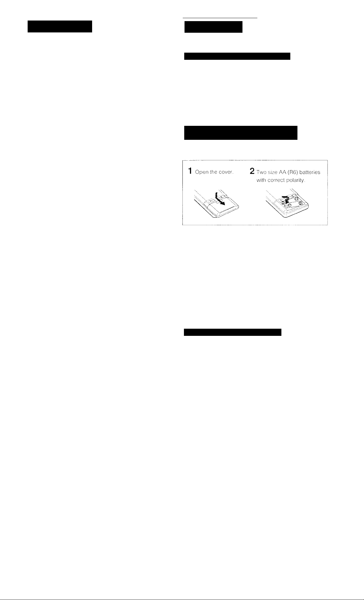
inserting the Batteries into the Remote Commander
Before operating remote comimander, install the batteries as
shown.
...........................................................
....................
(1)
(1)
Do not throw away the carton and packing material!
It will be an ideal container when transporting the system for
repair work, etc.
On operation
Before making program source.connections, be sure to turn
the power switch off and unplug the unit.
On cleaning the cabinet
Clean the cabinet, panel and controls vv/ith a soft cloth lightly
moistened with mild detergent solution. Do not use any type
of abrasive pad, scouring powder, or solvent such as
alcohol or benzine.
For the customers in the U.S.A.
For detailed safety precautions, see the "IMPORTANT
SAFEGUARDS" leaflet.
If you have any question or problem concerning your unit,
please consult your nearest Sony dealer.
To avoid damage caused by battery leakage and corrosion
When tlie comiTiander will not be used for a long time,
remove the batteries.
Battery life
Normal operation can be expected about a halt year using
Sony SUM-3 (NS), and a year using Sony AM-3 (NW)
alkaline batteries.
When the batteries are run down, the remote commander
will not operate the unit, in this case, replace batteries with
new ones.
Selecting the AM Tuning Interval
The AM tuning interval is preset to 10 kHz. To use the
receiver where the frequency allocation system is based on
a 9 kHz interval, make the following adjustments.
1 Turn on the power and tune In any AM station.
2 Turn off the power,
3 Press the POWER button while pressing the INDEX
SELECTATUNING + button.
To reset the AM tuning interval, repeat the above steps.
Caution
When the interval is changed, all preset stations which you
have memorized will be erased. After changing the interval,
be sure to preset the stations again.
5
Page 6
Hooking Up the System
At first, this section describes about the antenna connection and then the connection
with the other equipment. After that, it shows about the speaker connection and about
the AC outlet.
• Do not connect the power cord to an AC outlet nor press
the POWER switch before accomplishing all other
connections.
• The cable connectors should be fully inserted into the
jacks. Loose connection may cause hum and noise.
• Jacks and plugs of the connecting cord are color-coded
as follows:
Red jacks and plugs: For the right channel of audio
signals
White jacks and plugs: For the left channel of audio
signals
Yellow jacks and plugs: For video signals
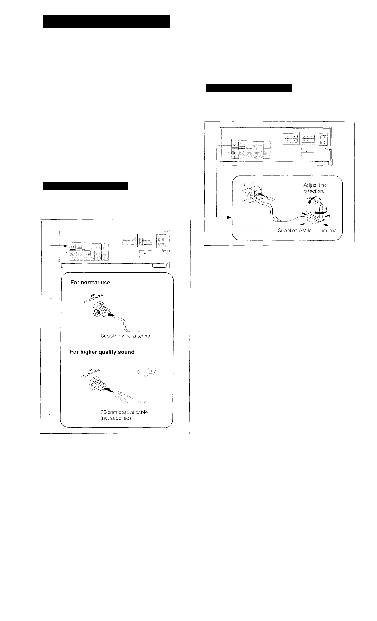
Connecting an FM Antenna
Though the wire antenna is supplied with this unit, the higher
quality sound will be obtained with the 75-ohm coaxial
cable.
Connecting an AM Antenna
The AM broadcast is enough received with the supplied AM
loop antenna. However, the connection of insulated wire is
also available for areas with difficult AM reception.
For areas with difficult AM reception
In areas with troubled reception, connect a 6 to 15-meter
(20 to 50-feet) insulated wire to the AM antenna terminal.
Extend this out of doors if possible, keeping the greater
portion horizontal.
(There is no need to disconnect the supplied antenna.)
6
To prevent hum
Connect the ground wire to ANTENNA ground terminal (rP).
When an outdoor antenna is installed, be sure to connect
the ground wire for lightning protection.
Page 7
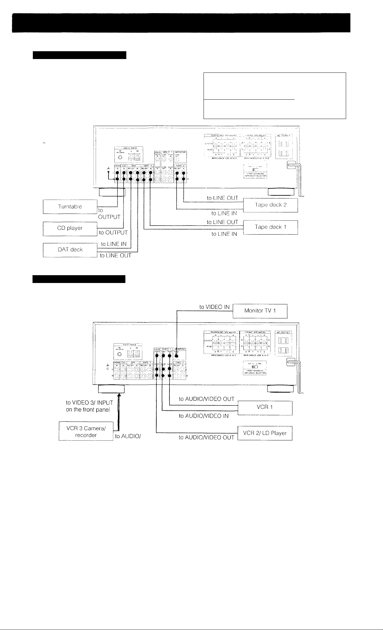
Connecting Audio Equipment
Receiver other equipment
White
White
@ i_
-X
■ X
Red
-t53=._»@ R
Red
Connecting Video Equipment
VIDEO OUT
7
Page 8
Hooking Up the System
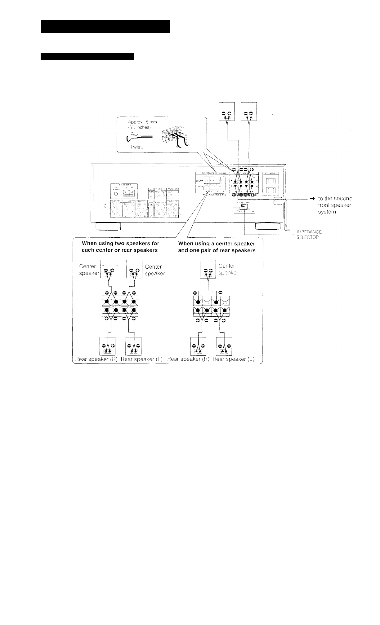
Connecting Speaker Systems
Front, center and rear speakers can be connected to this unit.
Front Front
speaker (R) speaker (L)
On the IMPEDANCE SELECTOR
The STR-D1011 has the IMPEDANCE SELECTOR for front
speakers.
When using the front speakers having nominal impedance
from.,4 ohms or higher, set to the 4 Q. position.
When using the front speakers having nominal impedance
from 8 ohms or higher, set to the 8 Q position.
Note
Use the front speakers having nominal impedance of more
than 8 ohms in the SURROUND mode.
8
Note
When connecting the speaker cord to the speaker terminal,
make sure that the polarity (+ and -) of the speaker cord is
correct. If the polarity is reversed at either speaker, the
sound will be distorted and will lack bass.
Page 9
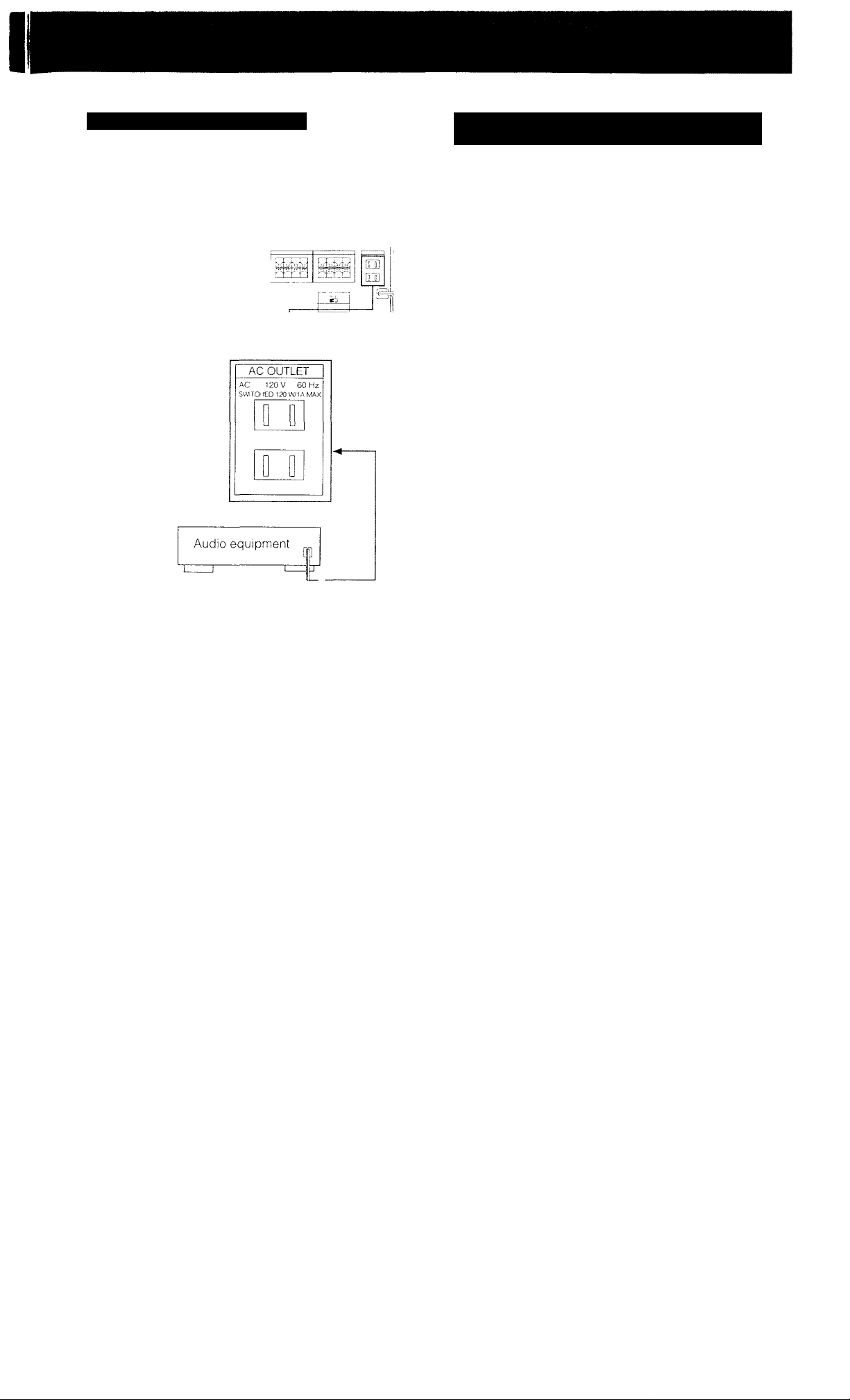
Connecting to the Power Outlet
By connecting the power cord of the other audio equipment
to SWITCHED AC OUTLET, this unit can supply the power
source to the other audio equipment.
o lJJ!
JiL
Selecting the Mode of the FUNCTION/SOUND FIELD/PRESET TUNING Buttons
There are two kinds of modes for the FUNCTION/SOUND
FIELD/PRESET TUNING buttons. One is the "Auto mode"
and the other is the "Manual mode".
• Auto mode
The FUNCTiON/SOUND FIELD/PRESET TUNING buttons
are factory preset to the auto mode:
After one of the FUNCTION buttons, SOUND FIELD LINK,
SOUND FIELD ON/OFF or SOUND FIELD USER/PRESET is
pressed, the FUNCTION/SOUND FIELD/PRESET TUNING
buttons change to the SOUND FIELD mode automatically.
When TUNER is pressed, these buttons function as
numeric buttons.
• Manual mode
When you press the POWER switch while pressing MODE
SELECT, the FUNCTION/SOUND FIELD/PRESET TUNING
buttons are set to the manual mode.
With MODE SELECT, you can select the desired mode.
To return to the auto mode, perform the same procedure
again.
Caution
Be careful that the total power consumption of each
equipment connected to the outlets on the receiver does not
exceed 120 watts.
Do not connect electrical home appliances such as an
electric iron, fan, TV, or other high-wattage equipment to
these outlets.
9
Page 10
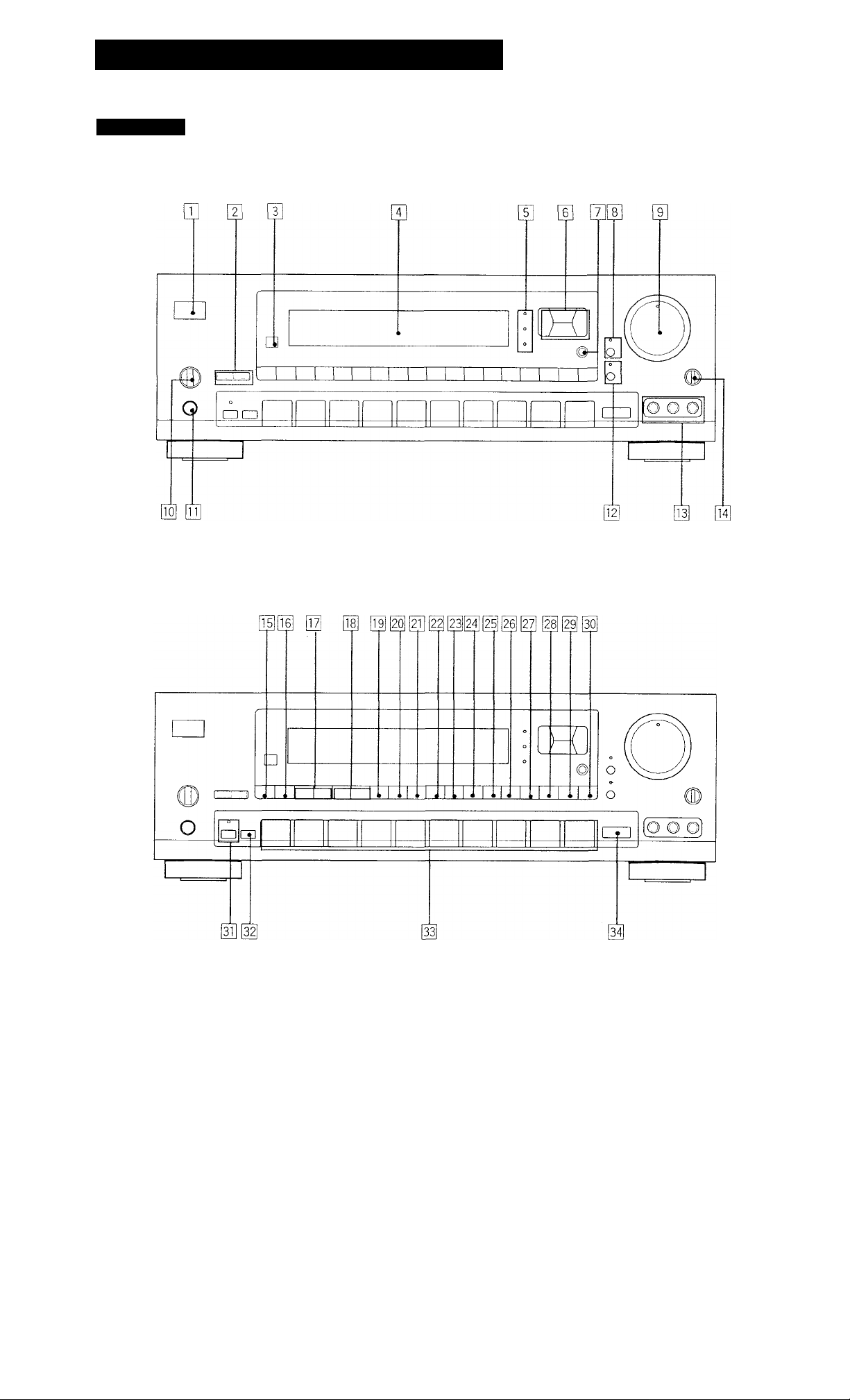
Identifying the Parts and Controis
Front Panel
10
Page 11

[n POWER switch
d] DISPLAY INDEX button (See pages 18, 22.)
[U EDIT VIDEO/AUDIO buttons (See pages 25, 26
¡A1 Remote sensor
[4] Display
[5] CURSOR MODE indicators
(See pages 16, 21,30, 31,33, 36.)
[s] Cursor mode operation buttons
(See pages 16, 21,30. 31. 33, 36.)
Iz] CURSOR MODE button
(See pages 16, 21, 30, 31, 33, 36.)
[s] DBFB button and indicator (See page 14 )
[U MASTER VOLUME control (See page 14 )
|T0| SPEAKERS selector (See page 14.)
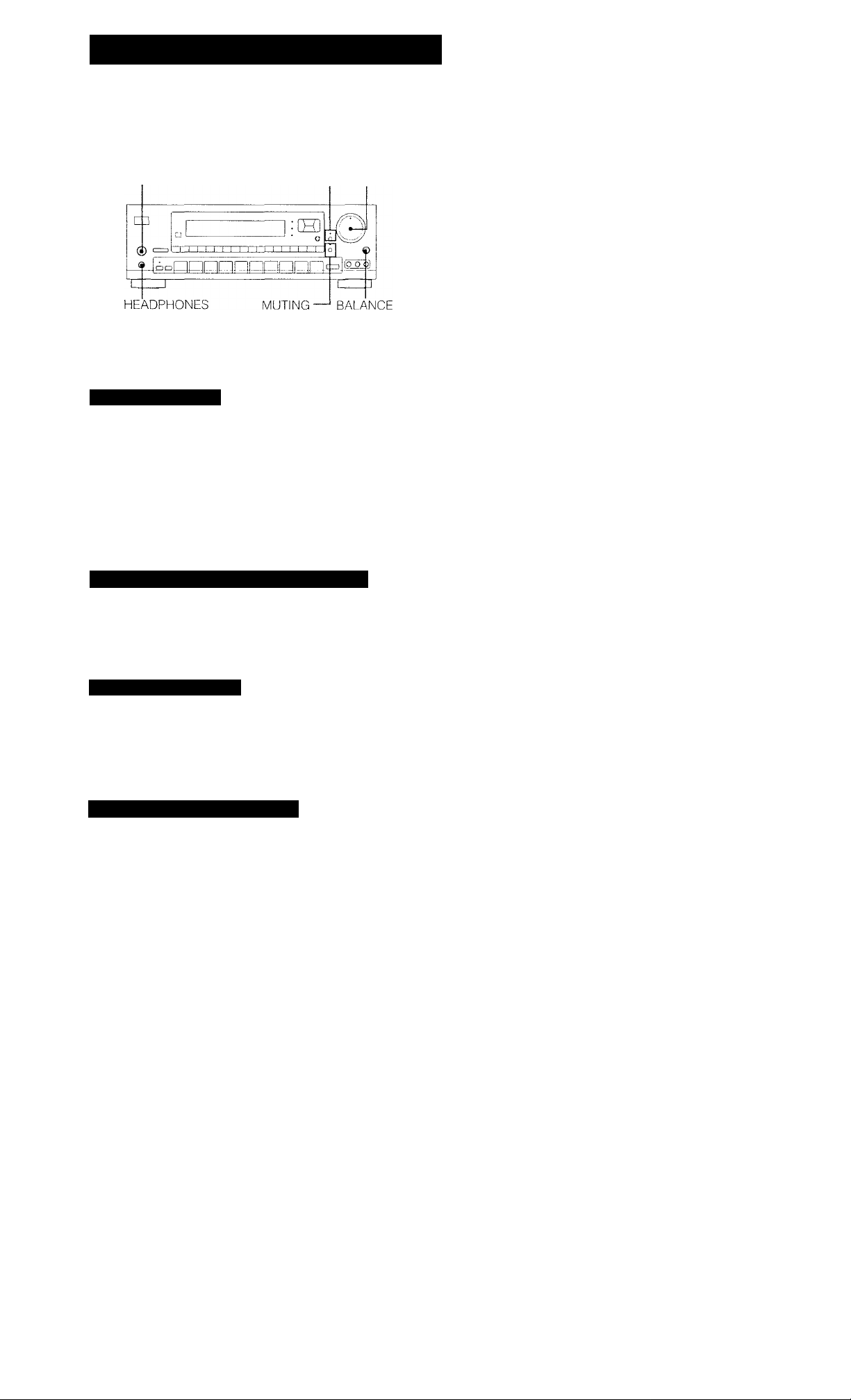
lH] HEADPHONES jack
¡H] MUTING button and indicator (See page 14 )
[H VIDEO 3/INPUT jacks
[it] index SELECT/TUNING -/+ buttons
(See pages 18, 22.)
d PRESET TUNING -/+ buttons (See page 22.
[d TUNING LEVEL button (See page 18.)
d MEMORY button (See pages 16, 19, 21.)
[2T] DIRECT TUNING button (See page 17.)
id FM MODE button (See page 17.)
[23] FM/AM button (See pages 17, 18.)
[24] SOUND FIELD LINK button (See page 37.)
d SOUND FIELD ON/OFF button (See pages 30, 31.)
d SOUND FIELD USER/PRESET button
(See pages 33, 36, 37.)
d DOLBY PRO LOGIC MODE button
(See pages 29, 30.)
d EQUALIZER FLAT button (See page 36.)
iH] BALANCE control (See page 14.)
[m DISPLAY GRAPHIC button (See page 36.)
d EQUALIZER SLOPE button (See page 36 )
d EQUALIZER BAND button (See page 36.)
d TAPE 2 MONITOR button and indicator
(See page 24.)
d SHIFT button (See pages 19, 20, 21.)
d FUNCTION/SOUND FIELD/PRESET TUNING buttons
(See page 9.)
d MODE SELECT button (See page 9.)
11
Page 12
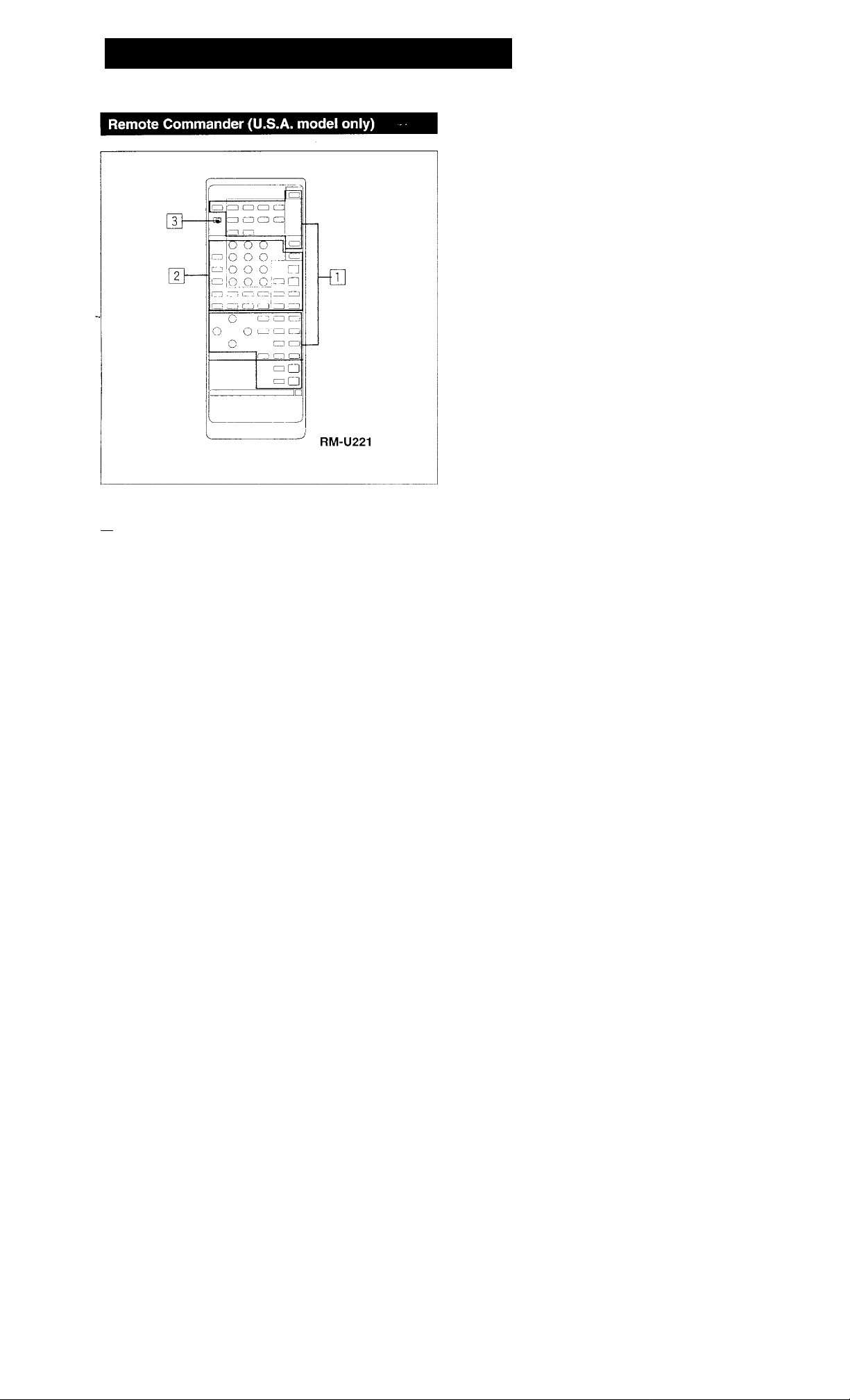
Identifying the Parts and Controls
I Other equipment control section
Numeric buttons (1 to 0): Designate the number.
ENTER: Press after designating the TV/VCR channel.
SHIFT: Select the memory page (A, B or C).
TV/VIDEO selector: Selects the program to see : TV or
VIDEO,
ANT TV/VTR button: Selects the output signal from the
antenna terminal on the VCR, either a TV signal or
VCR programs.
CH/PRESET +/-buttons: Select a preset channel,
INDEX: Set to the index tuning mode.
◄◄/►►: Fast winding/manual search
• : Recording
◄/►: Play
■: Stop
II: Pause
!◄◄/►►!: Locates a desired selection.
REV/FWD: Press • and REV or FWD at the same time,
D (disc) SKIP: Disc skip (for a CD player equipped
with a multi-disc changer)
SELECT: Changes the settings of the FUNCTION
buttons.
rn Receiver control section
FUNCTION:
DAT, CD, TUNER, PHONO, VIDEO 1, VIDEO 2, VIDEO
3, TAPE, DIGITAL 1,2: The each function Is selected
and the each unit enters its operating mode
automatically. (DIGITAL 1 and 2 do not function.)
SYSTEM OFF; Turns off the power of the whole system.
POWER: Turns on the power of the receiver
SOUND FIELD buttons
U/P (user/preset): Selects the USER or PRESET mode.
MODE: Selects the sound field mode.
ON/OFF: Turns on/off the sound field system.
BAND: Selects the frequency band of the equalizer,
EO: Turns on/off the setting of TONE controls.
T. (test) TONE: Generates a pink noise signal that is
sent in succession to each speaker.
CURSOR MODE: Select CURSOR MODE.
CURSOR operating buttons
REAR LEVEL +/- buttons: Control the volume of rear
speakers (surround level).
CENTER LEVEL +/- buttons : Control the volume of
center speaker (surround level).
DBFB button: Turns on/off the DBEB (Dynamic Bass
Feedback).
MUTING button: Mutes the sound.
MASTER VOL +/- buttons: Control the reoeiver
volume.
' SLEEP: Set to the SLEEP timer mode. In this mode, the
unit is automatically turned off after the designated
time.
Notes
• The button which has no name does not function.
• When designating the selection number which is more
than 10 in the CD, DAT or LD mode, press after
pressing the appropriate numeric buttons.
1 SYSTEM/TV mode switch
In TV mode (When setting the SYSTEM/TV selector
to TV)
Only MUTING, MASTER VOL +!- and the operative
buttons in TV section on the list described on the next
page can be used.
12
Page 13
Operating with the Remote Commander
Before operating the equipments with the remote commander, be sure to set the
receiver to the desired mode by pressing one of the FUNCTION buttons.
The FUNCTION buttons are factory set in the following list.
FUNCTION to be
Operating equipment
pressed
DAT
CD CD player
TUNER
PHONO
VIDEO 1
VIDEO 2 LD player
VIDEOS
TAPE Tape deck A
DAT deck
Tuner
(The receiver enters the PHONO mode.)
Betamax VCR (VCR 1)
8 mm VCR (VCR 2)
• When VIDEO 1, 2 or 3 is pressed, the power of the
selected video equipment and TV is turned on.
Operating the equipment
1 Press the desired FUNCTION,
2 Press ◄ (only for tape deck) or ► to start playback.
Changing the Settings of the FUNCTION Buttons
With the SELEOT button, you can replace the functions
stored in the FUNCTION buttons.
To change the settings of the FUNCTION buttons
1 Press one of the FUNCTION buttons to be stored.
2 Press SELECT.
3 Press 1 to 9 button to select the desired function within 30
seconds.
To reset to the initial state, press the blank button left next
to the 0 button.
4 Press ENTER.
To operate other unit temporarily without changing the
settings of FUNCTION
1 Press SELECT.
2 Press the 1 to 9 button to select the function.
3 Press the desired button.
After operating the unit, the receiver enters the previous
mode.
Operative buttons: POWER, ◄◄/►►, !◄◄/►►!, ■, ◄/►, ii,
•REC, D.SKIP, TVA/IDEO, ANT TVAfTR, CH/PRESET+/SHIFT, INDEX.
Example:
To record the program source on DECK A in the CD mode
1 Press SELECT.
2 Press 3 (DECK A),
3 While pressing •, press REV or FWD.
After operating DECK A, the receiver enters the CD mode
automatically.
List of operative buttons in SYSTEM mode (When setting
the SYSTEM/TV selector to SYSTEM)
Operating
equipment
ENTER
SHIFT
TVA/IDEO
ANT TV/
PRESET
INDEX
D.SKIP
REV^,
FWD^,
VTR
CH
+/-
►►
II
◄
►
■
TUNER
1
2
3
4
5
6
7
8
9
0
CD DAT DECK
•
•
•
• •
•
• •
•
• • • • •
•
•
•
• •
«
—
—
—
—
—
—
—
—
—
—
—
—
—
• •
•
• •
•
•
•
• •
— — —
•
—
—
— —
•
— — —
•
— — —
•
• • •
•
• •
•
•
—
• • •
• • •
— —
—
TV
A, В
•
—
—
—
•
—
—
—
—
•
—
—
— —
— —
— —
~ — — — —
• •
— —
— —
•
• •
—
• •
•
•
LDP VTR 1,
• • •
• • •
• • •
• • •
• • •
• • •
• • •
• •
•
• •
• • •
— —
•
•
—
— — —
—
—
—
— — —
—
—
— —
—
•
• •
•
•
• •
• •
• •
—
2, 3
•
•
•
•
—
—
—
•
•: The button is operative.
—: The button is not operative.
•*; The button can operate TV.
Note
To operate the unit correctly, the function mode of the
receiver should be same with that of the remote
commander. So, be sure to press the desired FUNCTION
button at first and then the operative button.
13
Page 14
Adjusting Basic Audio Controis
You can enjoy superb sounds using the audio adjustment
functions as shown below.
MASTER
SPEAKERS
Adjusting Volume
To adjust volume
Turn MASTER VOLUME.
DBFB VOLUME
To reduce the sound to a low level temporarily (- 20 dB attenuation)
Press MUTING. The indicator lights up.
Press again to restore the same listening level as before.
Adjusting Left and Right Sound Balance
Adjust BALANCE to correct stereo imaging, when the
speaker position is not symmetrical.
Reinforcing the Bass
Press DBFB (Dynamic Bass Feedback) so that the DBFB
indicator lights up. Press again to turn off the effect so that
the indicator goes off.
Selecting the Speaker System
To drive speaker system A: Set SPEAKERS to A.
To drive speaker system B: Set SPEAKERS to B.
To drive both speaker systems A and B (series connection):
Set SPEAKERS to A + B.
For headphone listening: Connect headphones to
HEADPHONES and set SPEAKERS to OFF.
IMPORTANT
Speaker systems A and B are series connected. When only
one speaker system is connected, no sound can be heard
at the A + B position.
14
Page 15
Selecting a Program Source
r
POWER — ON
cn
o
_o_„í^írinnngnnarM^
:E]
Turntable
CD player
Tape deck
DAT
VCR
LD player
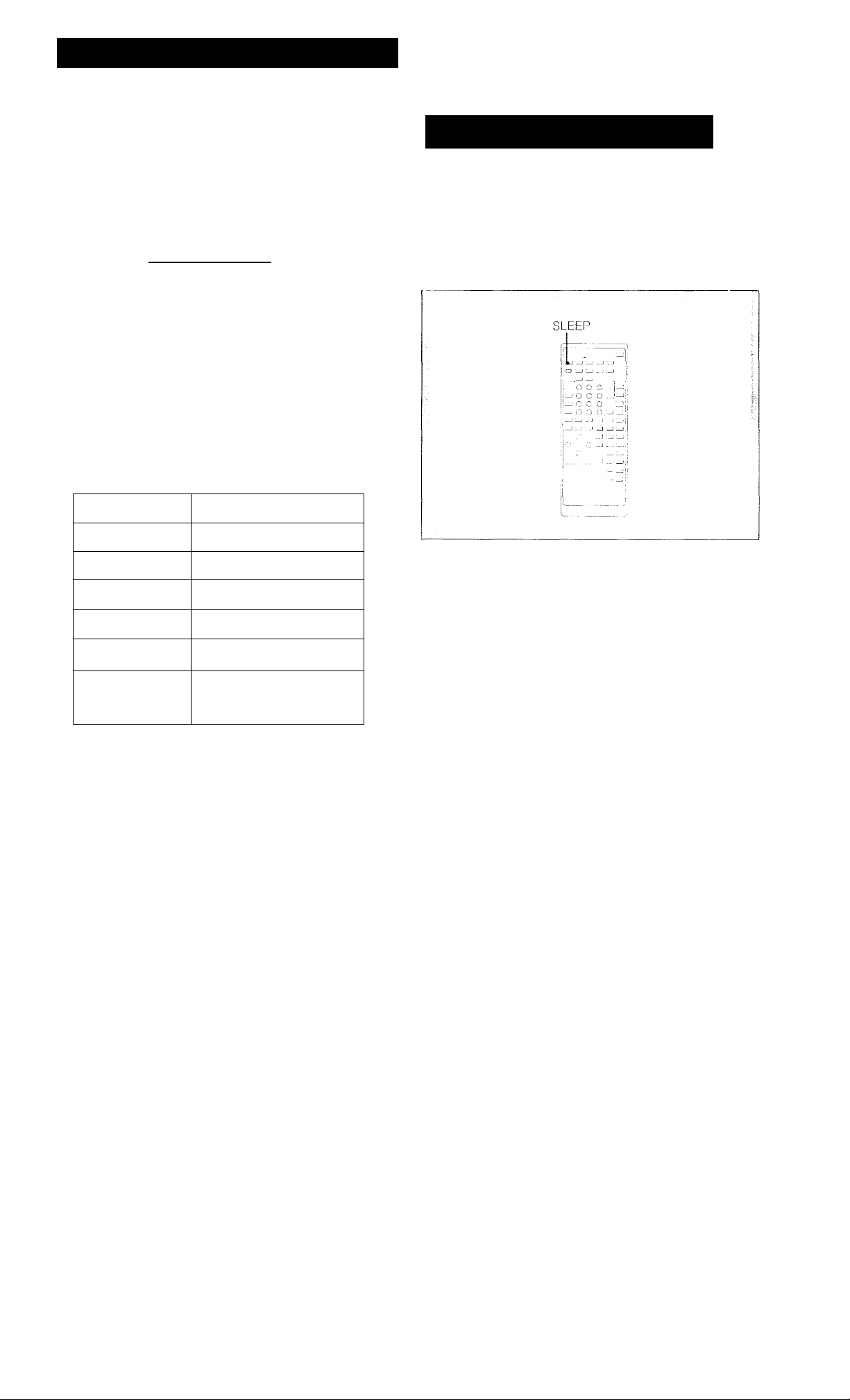
To Turn Off the Power at the Desired Time (The Sleep Timer Function)
This receiver has the sleep timer function. With this
function, you can turn off the power automatically at the
desired time by designating the turn-off time.
Press SLEEP on the remote commander when the power is
on. Each time SLEEP is pressed, the designating time is
displayed in the following order:
2 hours -► 1 hour and 30 minutes -► 1 hour -* 30 minutes
— SLEEP OFF.
Select the progam source.
What you select
Phono record
Radio Broadcast
Compact disc
DAT program DAT
Taped program TAPE 1, TAPE 2 MONITOR
Video program
When one of the FUNCTION buttons is pressed, the
indicator of the funotion you have selected appears on
the display. Select the function with the remote
commander, the power switches of both this receiver and
the selected equipment are turned on.
Start playback of the selected program.
Pressed
PHONO
TUNER
CD '
VIDEO 1, VIDEO 2/LD,
VIDEO 3
To change the turn-off time
1 Press SLEEP and the remaining time is displayed.
2 Press A or V to change the sleep time. The sleep time is
changed by 1 minute. It can be changed up to 6 hours
and 00 minute (and 00 second).
To check the remaining time of the sleep timer
Press SLEEP. The remaining time is displayed.
Note
When the remaining time display returns to the function
display, the function display is dimly lit on the display.
15
Page 16

Selecting a Program Source
Labeling the Program Source
You can input program sources except TUNER under index
names you create (up to 9 characters): for example,
PHONO, CD etc.
Press MEMORY.
The MEMORY indicator appears on the display and
goes off when the memory is finished.
Repeat steps 1 to 4 for all other program sources you want to assign an index name to.
If you input an already stored source under any other index name
Only the last selected index name will be valid. Each
program source can be stored under only one index name.
To clear the index name
Turn off the POWER switch or select another program
source.
Usable letters and symbols
!(space)—#-^7o&'( )*+,-./0123456789::<=>?tABODE
FGHIJKLMNOPQRSTUVV\/XYZ[\]ll_iabcdefghijklm
nopqrstuvwxyz
16
Page 17

Receiving Broadcasts
Tuning in a Station Directly (Direct Tuning)
Enter the frequency with the numeric buttons.
The entered frequency is displayed.
Example 1: FM 102.50 MHz
1 0 2 5 0
III II II
FM
1 U L . J U
Example 2: AM 1350 kHz
1 3 5
1 11 1 1
AM
1 J J U
kHz
To correct the entered frequency
Repeat steps 3 to 4.
For entering AM frequencies
You need not enter the last "0"
However, if you have changed the AM tuning interval to 9
kHz, enter all the digits.
If you enter a frequency not covered by the tuning
interval
The entered value is automaticaliy rounded up or down to
the closest value covered by the tuning interval.
Tuning intervals for direct tuning are the followings:
FM: 50 kHz interval
AM: 10 kHz interval (changeable to the 9 kHz interval)
(See page 5)
When the entered frequency does not exist in the receivable frequency range
The entered digits (up to 5 digits for FM or up to 3 digits tor
AM) blink in the frequency display area, and reception does
not take place.
If this occurs, press DIRECT TUNING again, and enter the
correct frequency (the frequency range of the receiver is
87.50 to 108.0 MHz for FM, and 530 to 1710 kHz for AM).
When an FM stereo program is noisy
When the unit receives an FM stereo program, the STEREO
ihdicator lights on the display. If the stereo program is noisy,
press FM MODE to change the mode over the MONO. This
eliminates the stereo effect, but the noise will be greatly
reduced.
To return to the stereo mode, press FM MODE again.
17
Page 18

Receiving Broadcasts
Automatic Tuning
When you do not know the frequency of the station to be
received, proceed as follows.
POWER
— ON
Press TUNER.
о ;
О !
24
0.0 _
Tj i G
zi'CQ.QIS I
Press INDEX SELECT/TUNING - or + until the desired station is received..
INDEX SELECT/TUNING
For a lower
frequency
When a station is received, automatic tuning stops.
If the automatic scan stops frequently (for FM reception only)
You can receive only the strong stations by pressing
TUNING LEVEL. HIGH appears on the display.
To receive all receivable stations again
Press TUNING LEVEL so that HIGH goes off.
For a higher
frequency
Frequency or the station index name you created is
displayed.
The FUNCTION buttons change to the numeric
buttons.
When the index name is displayed, press
DISPLAY INDEX to set to the FREQ mode.
DISPLAY
The frequency appears on the display.
Select FM or AM.
18
Page 19

Presetting Stations (Station Preset)
A total of 30 FM/AM stations can be memorized in any
desired sequence.
4 While MEMORY appears, select the memory page
(A, B or C).
|~ SH^ j
Each time SHIFT is pressed, A, B or C is indicated
cyclically.
5 While MEMORY appears, press the desired
number.
2 fa A I [5
Repeat above steps for presetting other desired
stations.
Replacing a preset station
Preset another station on the number of the station to be
replaced. The previously preset station will be erased.
19
Page 20

Labeling the Preset Stations (Station Index)
You can divide preset stations under index names you
create (up to 5 characters)^ If you want to categorize the
preset stations by kinds of music, for example, create
indexes such as ROCK, JAZZ, etc.
Press MEMORY.
MEMORY appears on the display.
0 While MEMORY appears, select memory page (A,
B or C). ^^
SHiFT
7 While MEMORY appears, press the desired
number.
8 Repeat steps 2 through 7 for all other stations you
want to assign an index name.
To clear the index name
Press TUNER in step 4.
When pressing TUNER in step 3 or 4
• The index name blinks and the index name you already
created is displayed cyclically by pressing a or v.
• To designate the same index name as the one you already
created, select the desired name by pressing a or v and
then follow step 6.
If you store an already categorized station under any
other index name
Only the last selected category will be valid. Each station
can be stored under only one index name
To display the frequency and index name of preset
stations
Each time DISPLAY INDEX is pressed, frequency and index
name of the preset station are alternately displayed.
Usable letters and symbols
!(space)-*#-^%&'( )*+,-/0123456789::<=>?tABODE
FGHIJKLMNOPQRSTUVWXYZ[\]ll_iabcdefghijklm
nopqrstuvwxyz
21
Page 21

Receiving Broadcasts
Tuning in a Preset Station (Preset Tuning)
There are two ways to perform the preset tuning.
In the method A, the direct tuning, select by designating the
desired preset station number directly with the numeric
button. In the method B, the scan tuning, select the preset
station with the PRESET -/+ button.
Method B: Scan tuning
1
Press TUNER.
Frequency or the station index name you created is
displayed.
The FUNCTION buttons change to the numeric
buttons.
Select the desired preset station with PRESET TUNING -or+.
PRESET TUNING
For a lower —
preset number
◄
A1 r AO
+
---
t .
-----------------
IMPORTANT
The memorized station is maintained for approximately one
month even if the power cord is disconnected from the AC
power outlet. If they are erased, store the stations again.
►
CO
—I—For a higher
preset number
B1 ^ ^ BO
+
-► C1
+
+ I
|A
20
Page 22
Receiving Broadcasts
Selecting a Station among the Preset Stations in the Index (Index Tuning)
POWER
— ON
G
O i I " :
Press TUNER.
TUNER
ST AD UM
Frequency or the station index name you created is
displayed.
The FUNCTION buttons change to the numeric
buttons.
ib o'o^
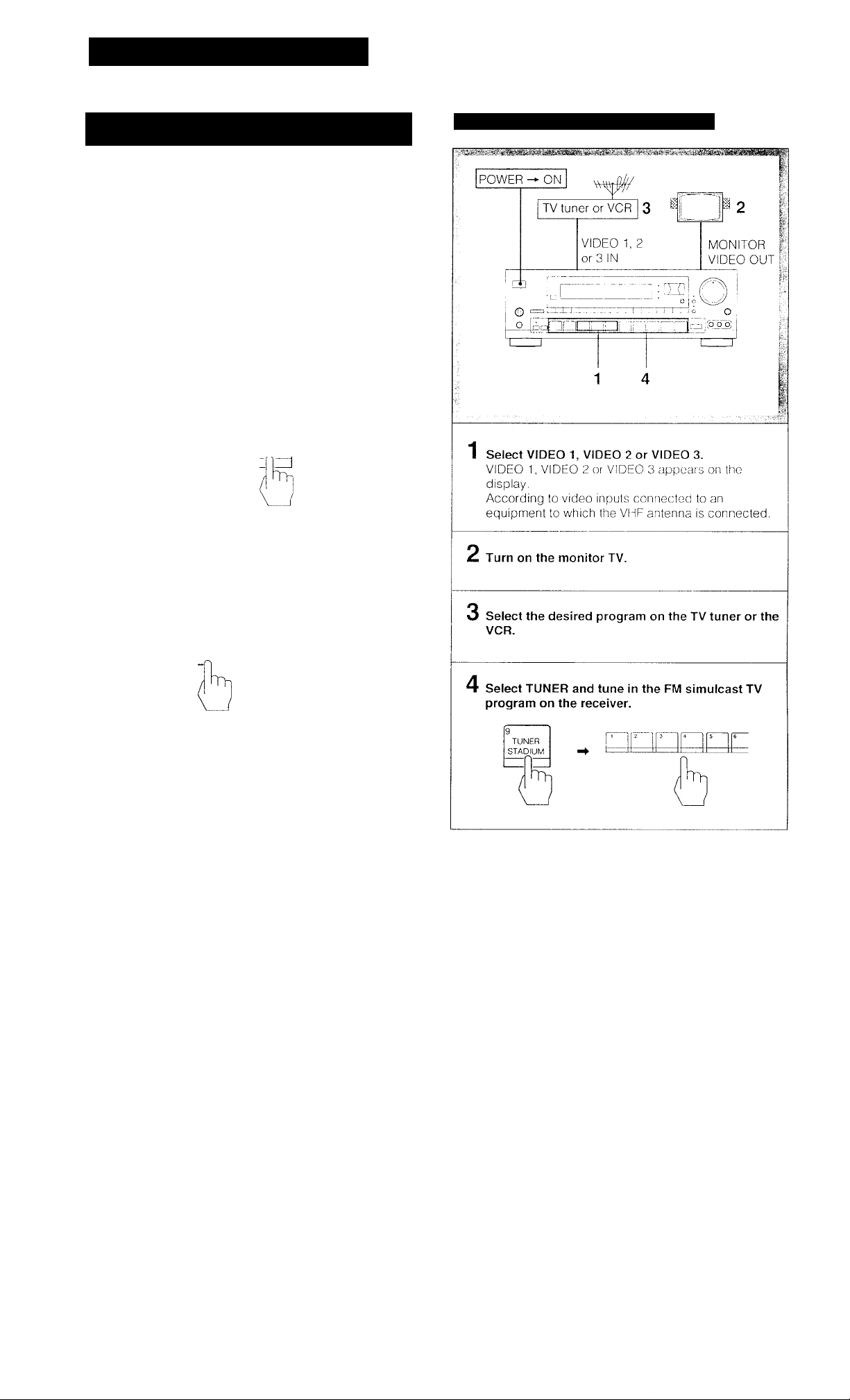
Receiving FM Simulcast TV Programs
Press DISPLAY INDEX to set to the INDEX mode.
DISPLAY
INDEX
3
When the no index name is
memorized,"
on the display.
Select the desired station.
• To select a station in the same index;
For lower
channnel
index station .
To select a index station other than the displayed
index station:
INDEX SELECT/TUNING
PRESET TUNING
For lower For higher
channnel channel index
index station station
PRESET TUNING
7
-------
--------
" appears
For higher
-channel
index station
--------T
22
Page 23
Selecting a Factory-preset Sound Effects
SOUND FIELD
DOLBY SUR
THEATER
LIVE
HALL
DANCE
JAZZ
OPERA
CHURCH
STADIUM
ACOUSTIC
Applications
For Dolby surround encoded video
programs
For movie programs on video tapes or
laser discs
For music programs on video tapes or
laser discs
For orchestral music, chamber music or
an instrumental solo
For dance music
For jazz
For operas or musicals
For church music or the pipe organ
For live concert in an open-air stadium
The surround effect is defeated and
only the equalizer effect can be
obtained.
Refer to page 28 for the characteristic of each mode.
23
Page 24
Recording an Audio Source
Recording onto an Audio Tape Deck or DAT Deck
! V »a V-
Audio signals
1 Select the desired program with the FUNCTION
buttons.
For an FM/AM broadcast, tune in the desired station
Tape Dubbing
O Audio signals
POWER ON
I
]
(D “
to TAPE 2 OUT
4,2
Tape deck 2
(for recording)
....: : :h]
Tape deck 1 or
I
■ 0 i
to TAPE 1
(or DAT) IN
DAT deck
(for playback)
o
9S> '
1,4
1 Insert the recorded tape into tape deck 1 (or the
DAT deck).
Set the tape (DAT) deck in the recording mode.
Start playback of the selected program source.
Monitoring the recorded sound
If you have connected a 3-head tape deck to the TAPE 2
jacks, you can monitor the recording results. While
recording or dubbing, press TAPE 2 MONITOR so that the
TAPE 2 MONITOR indicator lights up. To listen to the source
sound again, press the button again so that the indicator
goes off.
2 Insert a blank tape into tape deck 2 and adjust the
recording level.
3 Press TAPE 1 or DAT to select the deck for
playback.
4 Start the playback of the tape (or the DAT) in tape
deck 1 (or the DAT deck), and set tape deck 2 in
the recording mode.
Dubbing will start.
Note on tape dubbing
Tape dubbing is possible only in the following directions:
From
(playback deck)
Tape deck
connected to
TAPE 1 IN
DAT deck
connected to
DAT IN
Tape deck connected to TAPE 2 OUT
DAT deck connected to DAT OUT
Tape deck connected to TAPE 1 or 2
OUT
To
(Recording deck)
24
Press the FUNCTION buttons according to the playback
deck.
Page 25

Editing a Video Source
Video Tape Dubbing
If the AUDIO indicator is lit on the display, press the EDIT
AUDIO button to make the indicator go out.
Video signals
— Video Tape Editing —
To switch the playback VCR during dubbing
Press EDIT VIDEO. Each time you press the button, the
playback VCR switches from the VCR 2 to the VCR 3 (or the
VCR 3 to the VCR 2).
To view the other video source(s) on the monitor TV during dubbing
Press the appropriate function selector, VIDEO 1, VIDEO 2,
or VIDEOS.
To listen to an audio program during video tape dubbing
t Press the appropriate function selector.
2 Start the selected audio program source.
Select the playback VCR with EDIT VIDEO.
To select VCR 2, press EDIT VIDEO so that "2i> 1"
appears on the display.
To select VCR 3, press EDIT VIDEO so that "3i> 1"
appears on the display. '
Press VIDEO 2 or VIDEO 3 to select the video
signal to monitor on the monitor TV according to
the VCR to be played.
VIDEO 2: for the VCR 2
VIDEOS: for the VCRS
Set the playback VCR to the playback mode.
4 Set the VCR 1 to the recording mode.
Dubbing will start.
25
Page 26

Editing a Video Source
Adding New Sound on a Video Tape during Video Editing
During video tape editing, you can add the desired sound
on the recording VCR from various audio program sources.
^ Video signals
POWER — ON
VCR 2 12, 3, 6 5
to VIDEO 2
VIDEO IN
WD|~
>=> Audio signals
VCR 1 6
to VIDEO 1
VIDEO OUT/
AUDIO OUT
■nr
trtriitr
2, 3,6
Turntable
CD player
Tape deck
DAT deck
Release the pause mode of the playback VCR and set the VCR 1 to the recording mode.
Start playback of the selected audio program source.
Video dubbing starts and the audio program source
is also recorded on the VCR 1 simultaneously.
1 Select the playback. VCR with EDIT VIDEO.
To select VCR 2, press EDIT VIDEO so that ”2i> 1"
appears on the display.
To select VCR 3, press EDIT VIDEO so that "3o 1”
appears on the display.
Set the playback VCR to the playback mode.
At the point where audio dubbing starts, press the pause button on the playback VCR.
Press EDIT AUDIO.
AUDIO appears on the display.
Select the audio program source.
26
Page 27

What Is the Digital Signal Processor
TheSTR-D1011 incorporates digital signal processing
circuitry which consists of a digital surround processor and
a digital parametric equalizer.
• The digital surround processor electronically reproduces
the acoustics of various listening situations.
• The digital parametric equalizer controls the output level
of specific frequencies to finely adjust the frequency
responses.
These 2 digital sound effects allow you to create the
optimum sound quality and sound atmosphere in your room.
10 recommended sound field programs (combination of
settings of the surround and parametric equalizer have been
preset in the factory. Since these programs are appropriate
for the most types of music and listening situations, you cari
enjoy the digital sound effects by just selecting the sound
field programs according to the program source. And you
can also manipulate various parameters to finely tune the
factory-preset settings to your room, or create original sound
effects as you like. (Pages 32 to 37)
This manual described aoout the sound field program in the
following order:
Surround effect
Digital parametric equalizer
Storing your private sound field program
27
Page 28

Sound Field Setting
Table of Adjustable Parameters
The surround sound and digital parametric equalizer have
each adjustable parameter.
SOUND
Parameter
Equalizer
Room size
Wall
Seat position front/rear
Seat position ieft/right
*o
c
Effect level
o
(A
T3
Reverb time
c
3
o
u.
Delay time
3
CO
Rear level
Center level
FIELD
DOLBY
SUR
0
X
X
X
X
X
X
0
0
0
THE
ATER
0
0
0
0
0
0
0
X
0
0
Refer to pages 30 to 361or adjusting these parameter.
LIVE HALL DANCE
0 0 0
0
0 0 0
0 o 0 0
0 0
0 0
0 0
0
0 0 0
0 0 0
X X X
o 0 0
0
X X
JAZZ
0
0
0
0
X
0
X
OPERA CHURCH STADIUM ACOUS
TIC
0
0
0
0
0
0
0
X
0
X
0
0
0
0
0 0
0
0 0
X X
0 0
X
0
0
0
0
0
X
o
X
X
X
X
X
X
X
X
X
28
Page 29

Getting Ready for Dolby Surround Sound
This section describes about selecting the speaker
configuration and then adjusting the speaker volume and
the delay time of the rear speakers so that you can enjoy the
Dolby surround sound.
Placement of Speakers and Selecting the PRO LOGIC MODE
The Dolby Pro Logic Surround Decoder has the same
functions for playback, such as movie theaters and gives a
theater-like experience in your listening room, naturally
reproducing the audio sound field.
The STR-D1011 incorporates a decoder which reproduces
the specially encoded surround sound of Dolby surround
video programs.
In the Dolby surround mode, select the speaker operation
mode according to your speaker configuration by pressing
the DOLBY PRO LOGIC MODE button. Each time the
DOLBY PRO LOGIC MODE button is pressed, the DOLBY
PRO LOGIC MODE is changed in the following order:
NORMAL — WIDE — PHANTOM ^ 3 CH, LOGIC
l:
3
WIDE mode
Select this mode if you use a medium to big center speaker.
PHANTOM mode
Select this mode when you play back a Dolby surround
program source without using a center speaker. The sound
of the center channel is output from the fmnt (L and R)
speakers.
Front speaker (L)
ront speaker (R)
NORMAL mode
Select this mode it you use a small center speaker. The
bass sound of the center channel is output from the front
speakers, as a small speaker cannot produce enough bass.
Rear speaker (L) Rear speaker (R)
3CH. (Channel) LOGIC mode
Select this mode when you play back a Dolby surround
program source only with the front and center speakers.
The sound of the rear channel is output from the front (L and
R) speakers.
Some commercially available software may have Dolby
surround processed sound tracks even though it is not so
indicated on the package.
29
Page 30

Getting Ready for Dolby Surround Sound
Adjusting the Speaker Volume
5 Press CURSOR MODE.
To enjoy the surround sound to the maximum on playing
any program sources, adjust the front, center, and rear (if
connected ) speakers to the same volume level. The
adjustment must be done with a test tone in the DOLBY
SUR mode, but the level once adjusted can be used for all
surround modes.
You can adjust the volume level from your listening position
by using the remote commander.
The SUR (surround) indicator lights up.
To adjust the level of center speakers
Press A or V to select the center level mode and
then adjust the level with <i or t> or CENTER LEVEL
+/- on the remote commander so that sound from
each speaker is heard in the same volume level at
the listening position, (When adjusting the VOLUME
control on the receiver, all speakers are adjusted
simultaneously.)
To adjust the level of rear speakers
Press A or V to select the rear level mode and then
adjust the level with o or > or REAR LEVEL +/- on
the remote commander.
4,6
1 Press SOUND FIELD ON/OFF to ON.
The indicator of the last selected sound fieldlights
up.
2 Press DOLBY SUR.
DOLBY SUR appears on the display.
3 Select the Dolby pro logic mode with the DOLBY
PRO LOGIC MODE button according to your
speaker system.
Sequence of the test tone
In a system with a center speaker:
The test tone will be output automatically from the front L,
center, front R, and the rear speakers in succession.
In a system without a center speaker:
The test tone will be output automatically from the front left
and right speakers and the rear speakers alternately.
4 Press T. TONE on the remote commander to set
to on.
30
Page 31

Adjusting the Delay Time of the Rear Speakers
— for Dolby surround mode
The delay time is a time between the surround sound from
the front and that from rear speakers. The delay time is
adjustable from 15 ms to 30 ms.
POWER — ON
L
/d
\
LO
_ G ;
-, !'0~Q~0j i
■j
b
-----------------------
©
Q IcDt-J'
To memorize the speaker volume and the delay time of the rear speakers
Press USER/PRESET to set to the USER mode and then
adjust the speaker volume and delay time with the cursor
operation buttons.
1 Press SOUND FIELD ON/OFF to ON.
The last selected sound field Is displayed in box.
2 Press DOLBY SUR.
DOLBY SUR appears on t-he display.
3 Press CURSOR MODE.
The SUR (surround) indicator lights up.
Press A or V to select the delay time mode and
adjust the delay time with < or >.
To turn off the surround effect
Press SOUND FIELD ON/OFF to OFF.
The normal sound without surround and equalizer effect will
resume.
31
Page 32

Adjusting the SOUND FIELD program
Understanding the Digital Surround Processor
The sound heard in a place such as a concert hall or a
movie theater consists of direct sound, and early reflected
sound (early reflections) and a reverberative sound
(reverberation). The acoustics of the room affect the way
these three sounds are heard. We can estimate the size or
the type of a hall by listening to and differentiating these
three kinds of sound.
The STR-D1011 reproduces the early reflections and the
reverberation using its digital signal processor and allows
you to design a variety of sound field in your own room.
The unit incorporates 10 types of the SOUND FIELD
program, and you can select the desired SOUND FIELD
mode by pressing the SOUND FIELD button. Also you can
adjust several parameters within each mode to maximize
the effect in your listening room.
Characteristics of the SOUND FIELD program
SOUND FIELD
DOLBY SUR
THEATER
LIVE
HAlL
Characteristics
Decodes programs
processed with the Dolby
surround.
Adds the reflection of a
theater to decoded
signals of the Dolby
prologic decoder.
Adds the reflection of a
large concert hall to
decoded signals of the
Dolby prologic decoder.
Reproduces the acoustics
of a rectangular concert
hall with soft sound. It is
effective for playing a
program source with hard
sound.
Appropriate
music
source
Dolby
surround
processed
software
Dolby
surround
processed
movie
software
Doiby
surround
processed
music
software
Solo,
medium-size
orchestra or
classic
The sound transition of the direct sound, early reflections
and reberveration can be illustrated as below:
Note
Each surround mode has several internal (fixed) parameters
in addition to the adjustable parameters explained in this
section. Therefore, surround modes will not become the
same even if you set all adjustable parameters the same.
DANCE
JAZZ
OPERA
CHURCH
STADIUM
ACOUSTIC
The equalizer boosts high
and low frequencies, and
the dynamic sounds are
reproduced.
Reproduces the acoustics
of a live house. The
equalizer boosts high
frequencies, adding
sharpness to sounds.
Reproduces the acoustics
of an opera house,
keeping the clearness of
the vocal music.
Reproduces the acoustics
of a church made of wood
Reproduces the acoustics
of an outdoor stadium with
a long pre-delay time. It is
effective for playing a
program source recorded
in a stadium.
The surround effect is
defeated.
Pops or
dance music
Jazz
Opera
Baroque
music, string
orchestra or
choral group
Pops or rock
music
32
Page 33

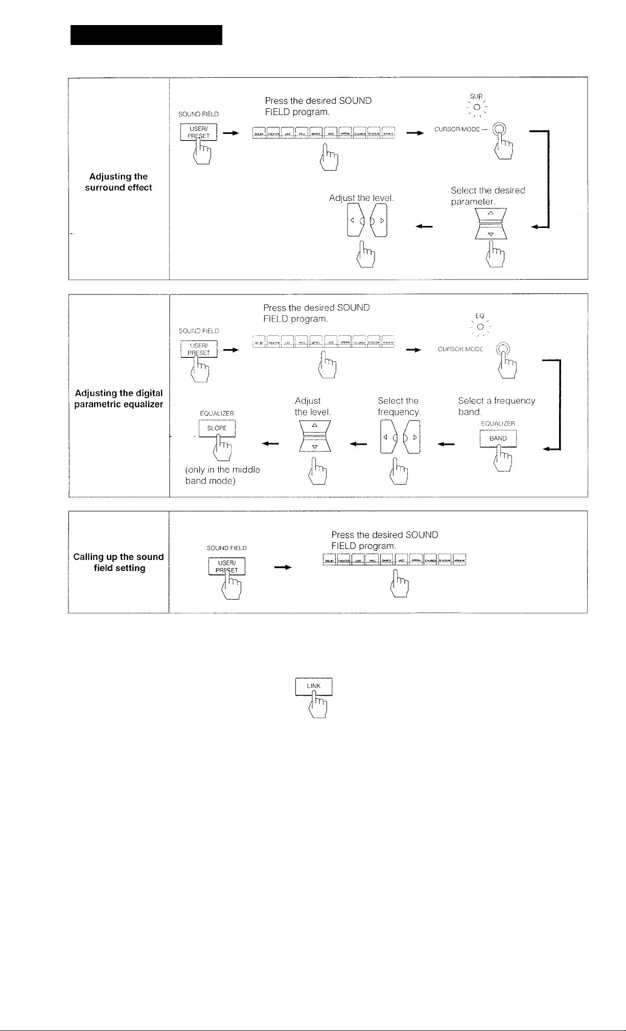
Adjusting the Surround Effect
Before adjusting parameters, play back the program
source. You can adjust parameters while listening to the
actual sound.
When you store a new SOUND FIELD effect
The previous SOUND FIELD effect is erased and the new
one will be replaced.
Even if AC power cord is disconnected
The stored data is maintained for approximately 1 month.
When selecting ACOUSTIC
ACOUSTIC does not have the surround effect and only the
equalizer effect can be available. So when selecting
ACOUSTIC, only the setting of parametric equalizer can be
adjusted.
Press USER/PRESET to set to the USER mode
when you store your private setting or to set to
the PRESET mode when you do not store your
setting.
Press the desired SOUND FIELD program.
3 Press CURSOR MODE to select the SUR
(surround) mode.
The SUR (surround! indicator lights up.
Press Л or V to select the desired parameter.
Adjust the parameter by pressing <a or i>.
Tips for adjusting the main parameters
The following procedure allows you to make the desired
sound field more effectively.
1 Select the desired factory-preset sound field program.
2 Adjust the effect level.
3 Adjust the reverberation time.
4 Adjust other parameters, it necessary.
33
Page 34

Adjusting the SOUND FIELD program
1
Room Size Simulation
The sound emitted from a sound souroe is reflected many
times between the left and right walls, ceiling, and floor
before it reaches our ears. In a large room, the sound takes
more time to bounce from one surface to another than in a
smaller room.
The ROOM parameter controls the spacing of early
reflections to simulate the room size. The S indicator on the
display signifies a small room, the L indicator signifies a
large room and the middle point designates the standard
room size.
Room Size S
Room Size L
I Wall Material Simulation
When sound is reflected by a wall made of soft material
such as wood or a wall covered with a curtain, the high
frequency components are reduced. A hard wall is highly
retlective and does not significantly effect the frequency
response of the reflected sound.
The WALL parameter controls the level of high frequencies
to simulate the wall material. The S indicator on the display
signifies a soft wall, the H indicator signifies a hard wall, the
middle point designates the standard wall made of wood.
Wall S
Wall H
Early reflections and reverberation
Low
Frequency
High
34
Page 35

I Seat Position Simulation
I Effect Level
When you sit in the front of a room, you will hear more direct
sound from the front speakers, and the component of
reflected sounds from the front speakers grows as you
move to the rear. Similarly, the component of reflected
sound changes when you move from left to right, and vice
versa. The F/R and L/R parameters control the balance of
the direct and reflected sound and other components of
sound to simulate your listening position.
When adjusting the F/R parameter, the F indicator on the
display signifies the front position of the room, the R
indicator signifies the rear position, the middle point of the
indicator designates the center position. When adjusting
the L/R-parameter, the L indicator signifies the left position
of the room, the R indicator signifies the right position, and
the middle point of the indicator designates the center
position.
Effect level is the combination of the level of early reflections
and reverberation. The L indioator on the display signifies
the lowest level and the H indicator signifies the highest
level. The adjustable level is divided into 20 segments. As
you select higher level, the room becomes more “live", and
as you select lower level, the room becomes‘"dead".
■ Reverberation Time
This parameter adjusts the length of the reverberation — the
time required for reverberative sound to decrease to -60 dB.
The S indicator on the display signifies the shortest
reverberation time, the L indicator signifies the longest
reverberation time.
Page 36

Adjusting the SOUND FIELD program
Understanding the Digital Parametric Equalizer
The parametric equalizer is a tone control system with
adjustable center frequency and slope (Q).
The STR-D1011 provides flexible equalization using oneband parametric equalizer with center frequency and
slope, and 2-band shelving equalizers with adjustable
turnover points.
The equalization curve appearing on the display allows you
to accurately adjust the sound quality. The parametric
equalizer effects all line output signals including
SURROUND (REAR. CENTER).
How to Adjust the Digital Parametric Equalizer
Before adjusting the digital parametric equalizers, play back
the program source. You can adjust the equalizer while
listening to the actual sound.
4 Press EQUALIZER BAND to select a frequency
band.
B: Bass
M: Middle
T: Treble
5 Press <3 or i> to select the frequency you want to
adjust.
Press A or V to raise or lower the level of the
selected frequency.
Adjust the frequency level of the mid range by
pressing EQUALIZER SLOPE if necessary.
8 Repeat steps 4 through 7 for other frequency
bands until you obtain the desired equalization
To make the equalization curve flat
Press EQUALIZER FLAT,
You can create a new equalization curve.
........''___
Press USER/PRESET to set to the USER mode
when you store your private setting or to set to
the PRESET mode when you do not store your
setting.
Press the desired SOUND FIELD program.
Press CURSOR MODE to select the EQ
(equalizer) mode.
The EQ (equalizer) indicator lights up.
'
_______________■ .c - ■ '
On the function of DISPLAY GRAPHIC
Every time you press DISPLAY GRAPHIC, the display of
equalizer eurve, real lime analyzer and peak hold is
cyclically switched. Each display shows as followings.
In the DOLBY SUR, LIVE or THEATER mode, the levels of
each channel are graphically displayed except Vi/hen the
equalizer curve is displayed.
— Equalizer curve shows the settings of the equalizer
controls.
— Real time analyzer (RTA type-1) shows the level of each
frequency range.
In the DOLBY SUR, LIVE or THEATER mode, the levels
of each channel are displayed.
— Peak hold mode (RTA type-2) shows that this mode
holds the highest input of each frequency range for
several seconds.
In the DOLBY SUR, LIVE-or THEATER mode, peak levels
of each channel are held for several seconds.
— Real time analyzer (RTA type-3) shows the highest level
of each frequency range.
In the DOLBY SUR, LIVE or THEATER mode, the highest
levels of each channel are displayed.
When the center frequency band overlaps the bass or
treble frequency band during adjustment
The setting level of each band will accumulate.
The equalization curve appears only between ±10 dB.
36
Page 37

Enjoying with Your Private Setting
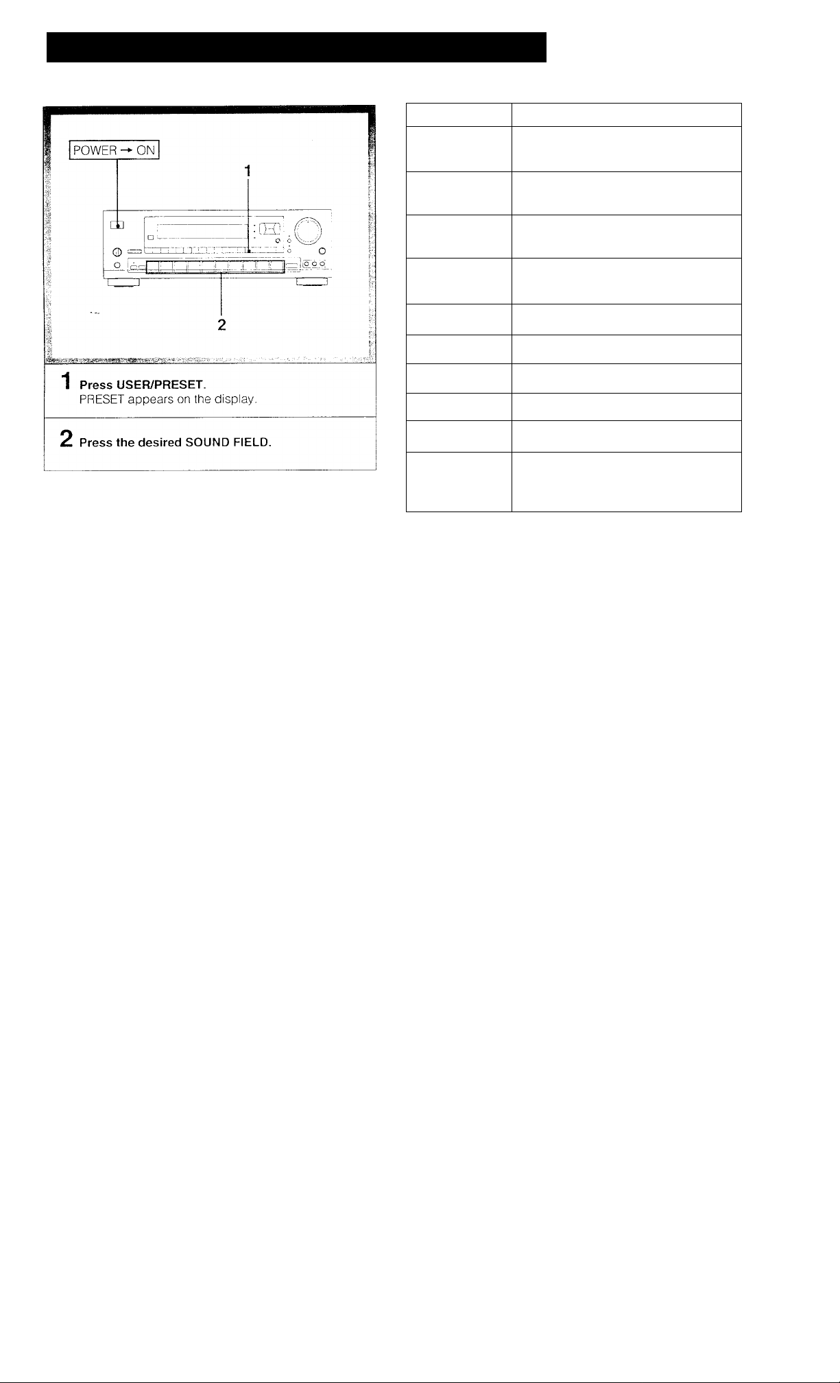
Calling up the Sound Field Setting
c#» J,• •'; i JV■ II»“’!t .A,;;;^**: S»*Si5'i'
POWER — ON
iV-7i
©
ro 6\
1 Press USER/PRESET to set to the USER mode
when you call up your private setting or to set to
the PRESET mode when you call up the factory
preset setting.
Press the desired SOUND FIELD program.
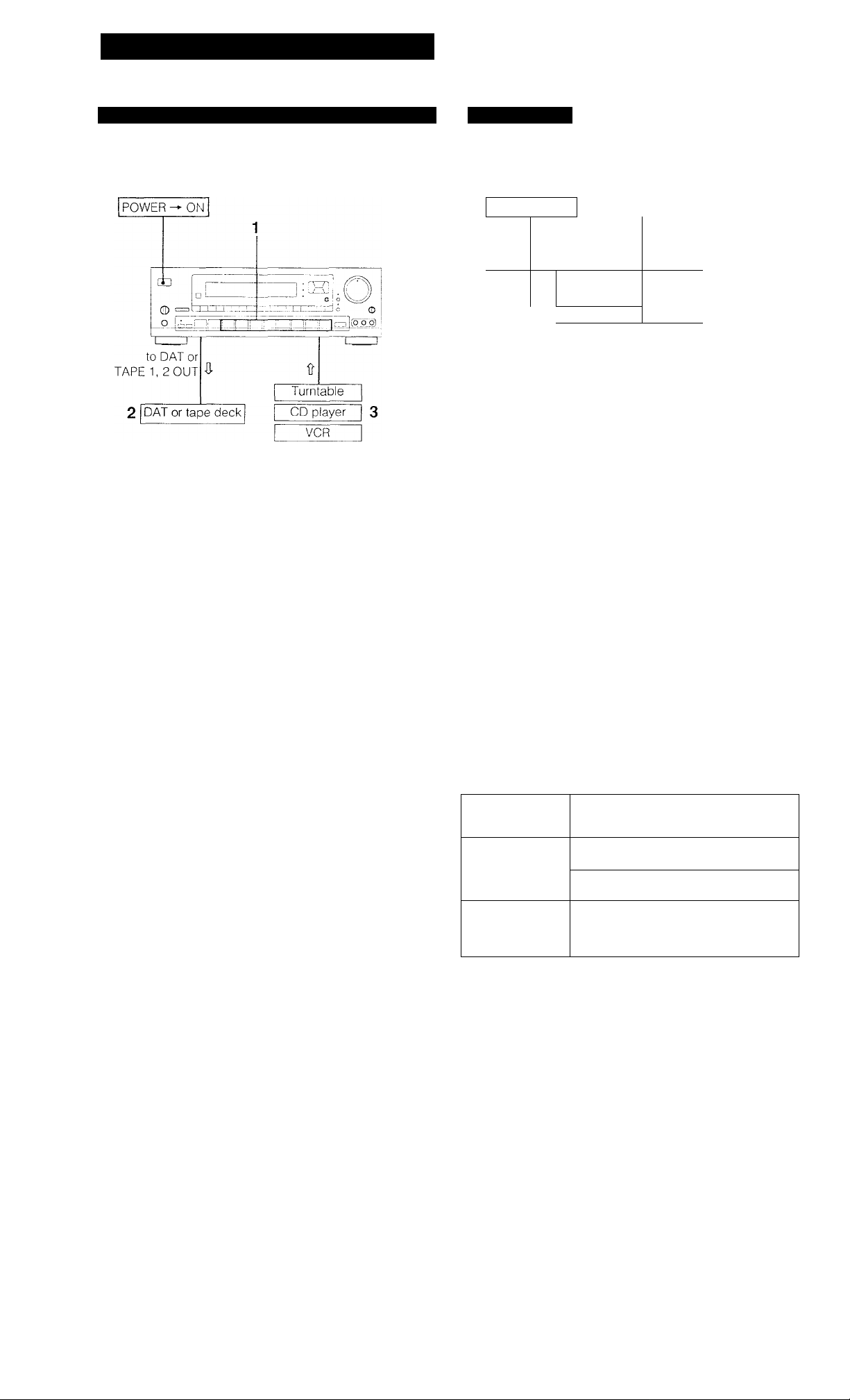
Linking the Sound Field Memory to Preset
Stations or Program Sources
POWER — ON
O
I
3
1,
Tune in a station or select the program source to
be linked with sound field data.
Press SOUND FIELD LINK.
Press the desired SOUND FIELD program.
Notes
• When other sound field is selected in the LINK mode, the
previous sound field setting linked with the preset station
or program source is replaced with the newly selected
one. Therefore, if you want to select other sound tield
without changing the sound field setting in memory, press
LINK to turn off the LINK mode and then select other
sound field.
• When the sound field setting is adjusted, the sound field
setting linked with the preset station or program source is
also changed.
37
Page 38

1 Troubleshooting Guide
Before proceeding through the check list below, examine the connections and the
procedures outlined in the manual.
Should any problem persist after you have checked the following items, consult your
nearest Sony dealer.
Problem
No FM station can be located by
Automatic tuning operation.
The STEREO indicator flickers or does not
appear when receiving stereo programs.
No station can be tuned in by Automatic
tuning operation.
No stations can be tuned in by pressing
PRESET TUNING +/-.
No sound is heard oven if you adjust
VOLUME.
Cause Solution
The signal strength ot the stations is too
weak.
A very weak FM station or a noisy FM
program is received.
The AM tuning interval is set incorrectly.
The signal strength ot the station is too
weak for Automatic tuning.
No stations have been preset.
The speaker or program source equipment
is not connected correctly.
The SPEAKERS selector is not set correctly.
TAPE 2 has been pressed for a program
source other than tape dock 2. (The
indicator Is lit.)
Press TUNING LEVEL to set the receiving
signal level low.
Check the antenna connection.
Adjust the antenna or connect an external
FM antenna.
Press FM MODE to set to MONO mode.
Change the tuning interval according to the
AM frequency allocation system of your
country. (See page 5)
Adjust the antenna.
Directly tune in the stations.
(See page 17)
Preset the stations. (See page 19)
Connect the equipment correctly.
Set the selector correctly. (See page 14)
Press the button to disengage.
-
No sound or sound at very low level is
heard from rear speakers.
Sound is heard only at a very low volume.
One channel does not transmit audio, or
the volume from the left and right speakers
Is unbalanced.
There is an abrupt loss of sound from
one or both of the speakers, and the
PROTECTOR indicator flickers on the
display.
A wrong function selector has been
pressed.
The function switch on the VCR is not set
correctly.
SOUND FIELD function is turned off.
Monaural program source is played back in
Dolby surround mode.
MUTING has been pressed. (The MUTING
indicator is lit.)
The BALANCE control is not set
appropriately.
The speaker or program source is not
connected correctly.
A short-circuit problem activates the
protective circuit.
Press the correct function selector.
Check and set it correctly.
Press SOUND FIELD ON/OFF to turn on the
function.
Select the other modes.
Press the button to disengage.
Adjust the BALANCE control.
Check and properly connect the
equipment.
Turn oft the unit, eliminate the short- circuit
problem and turn on the power again. If
there is no short-circuit problem, consult
your nearest Sony dealer.
38
Page 39

Problem
Cause
Solution
Sound transmitted from the speakers is
reversed.
There is lack of bass sound or the
instrument position is obscure.
Severe hum or noise is heard. The connecting cords are not shielded
--
Surround effect cannot be obtained.
The speakers are not oonnected correctly.
The ©/© connection of the speaker is
reversed.
type.
A transformer, motor, TV or fluorescent light
affects the connecting cords.
The audio components are too close to a
TV set.
The unit is not grounded.
The connections are loose.
The plugs and jacks are dirty.
The unit is in a wrong mode.
Surround circuit IS turned off.
Connect the right speaker to the R
SPEAKER terminals and the left speaker to
the L SPEAKER terminals.
Connect the speaker with the correct
phase.
Use shielded type cords.
Place the connecting cords in a location
away from a transformer or motor, and at
least 3 meters (10 feet) from a TV set or a
fluorescent light.
if both are used at the same time, separate
the TV from the audio components.
Connect the ground wire to the antenna
ground terminal.
Make secure connections.
Wipe the plugs and jacks with a cloth
lightly dampened with alcohol.
Press CURSOR MODE to set the SUR
(surround) mode.
Set the FUNCTION/SOUND FIELD/PRESET
TUNING buttons to the SOUND FIELD
mode and select an appropriate SOUND
FIELD.
Equalization curve adjustment is
impossible.
The FUNCTION buttons do not change to
the SOUND FIELD buttons even after
pressing one of the FUNCTION buttons
except TUNER or these buttons do not
change to the numeric buttons even after
pressing TUNER.
The remote commander will not operate.
The equipment cannot be operated by
using the remote commander.
The unit is in a wrong mode.
Equalization circuit is turned off.
The FUNCTION/SOUND FIELD/PRESET
TUNING buttons are set to the manual
mode.
The batteries are exhausted.
The commander head is not pointed
toward the unit's front.
There is an object between the commander
and the receiver.
The mode of the receiver is not same with
that of the remote commander.
Press CURSOR MODE to set the EQ
(equalizer) mode.
Set the FUNCTION/SOUND FIELD/PRESET
TUNING buttons to the SOUND FIELD
mode and select an appropriate SOUND
FIELD.
Set to the auto mode. (See page 9)
Replace the batteries with new ones.
Point the commander head toward the
receiver.
Remove the object.
Press the desired FUNCTION button again.
39
Page 40

Specifications
Audio Power Specifications
POWER OUTPUT AND TOTAL HARMONIC
DISTORTION
With 8-ohm load, both channels driven,
from 20 - 20,000 Hz, rated 120 watts per
channel minimum RMS power, with no
more than 0.04 % total harmonic
distortion from 250 milliwatts to rated
output.
Surround mode
(8 ohms)
FRONT (at 1 kHz)
CENTER* (at 1 kHz) 80 W
REAR (at 1 kHz)
■ (only in the DOLBY SUR, THEATER and LIVE modes)
Other Specifications
80 W/ch
30 W/ch
Output sensitivity/
impedance
MUTING
DBFB
DAT OUT,
TAPE OUT 1,2
VIDEO 1
HEADPHONES
250 mV
10 kilohms
Accepts headphones of high
and low impedance
-20dB
-rio dB at 70Hz
Digital signal processor section
Modulation (A/D conversion)
Demonstration (D/A conversion)
Sampling frequency
Equalizer Band
Turnover
frequency
Center
frequency
Level ±10 dB, 1 dB step
Slope (Q)
High Density Linear Converter
High Density Linear Converter
(Pulse D/A Converter)
48 kHz
3-band, Bass/Treble/Mid
Bass: 125 Hz- 1 kHz
Treble: 1 kHz - 8 kHz
Mid: 54 Hz-8 kHz
3-step selectable. Wide, Mid,
Narrow
** 78IHF
Amplifier section (Front)
Continuous RMS power output (8 ohms, at 20 Hz-20 kHz)
130 W-r 130 W
Dynamic power
output (in the
stereo mode)
Frequency
response
Damping factor
(8 ohms, at 1kHz)
Input sensitivity/
impedance
S/N
8 ohms,
at 1 kHz IHF
4 ohms,
at 1 kHz IHF
PHONO
CD, DAT,
TAPE 1,2
VIDEO 1,2,3
PHONO MM 2.5 mV, 50 kilohms
CD,DAT,
TAPE 1,2
VIDEO 1,2,3
PHONO MM 83 dB
CD, DAT
TAPE 1,2
VIDEO 1,2,3
185 W+ 185 W
235 W + 235 W
RIAA equalization curve ±0.5
dB
10 Hz-20kHz:“dB
50
250 mV
50 kilohms
76 dB" (A,2.5mV)
85 dB
78 dB” (A,150mV)
Surround ROOM SIZE
WALL 16-step adjustable
SEAT
POSITION F/R
SEAT
POSITION L/R
EFFECT
LEVEL
REVERB TIME 16-step adjustable
DELAY TIME" 15.0 ms-30.0 ms, 0.1 ms step
REAR LEVEL -1-10
CENTER
LEVEL***
INPUT
BALANCE
— (only in the DOLBY SUR, THEATER and LIVE modes)
16-step adjustable
16-step adjustable
16-step adjustable
20-step adjustable
-------
50 dB, 1 dB step
±10 —-50dB, 1 dBstep
Automatic
'* (only in the DOLBY SUR mode)
40
Page 41

FM tuner section
AM tuner section
Frequency range
Antenna terminals
Sensitivity at 50 dB
Usable sensitivity
S/N
Harmonic
distortfon at
1 kHz
IM distortion Mono
Separation 45 dB at 1 kHz
Frequency response
Selectivity 60 dB at 400 kHz
Capture ratio
AM suppression ratio
Image response ratio 70 dB
IF response ratio
Mono 80 dB
Stereo
Mono 0,3 %
Stereo 0.5 %
Stereo
87.5 - 108.0 MHz
75 ohms, unbalanced
18.3 dBf, 4.5 |uV (mono)
38.3 dBf, 45 pV (stereo)
11,2dBf,2pV(IHF)
74 dB
0.3 °/b
0.5 %
30 Hz - 15 kHz '^dB
1.2 dB
54 dB
70 dB
Frequency range
Antenna
Usable sensitivity
S/N
Harmonic distortion
Selectivity
Auto tuning threshold
Video section
Inputs
Outputs
General
Tuner section
System
Power requirements
Preamplifier
section
Power amplifier
section
530 - 1,710 kHz (with 10 kHz interval)
531 - 1,710 kHz (with 9 kHz interval)
Loop antenna
50 dB/m (at 1,000 kHz or 999 kHz)
54 dB (at 50 mV/m)
0.5% (50 mV/m, 400 Hz)
35 dB (9 kHz), 40 dB (10 kHz)
55 dB/m
VIDEO 1,2,3: 1 Vp-p 75 ohms
VIDEO 1, MONITOR: 1 Vp-p 75 ohms
PLL quartz-locked digital synthesizer
system
Low-noise NF type equalizer
Pure-complimentary SEPP
120 V AC,60 Hz
Spurious response ratio
RF intermodulation at 800
kHz
Auto tuning
threshold
80 dB ■
60 dB
Low 30 dBf
High 50 dBf
Power consumption USA model: 260 W
AC outlets
Dimensions (including
projecting parts and
controls)
Mass
Supplied accessories FM wire antenna (1)
Design and specifications are subject to change without notice.
Canada model: 320 VA
Two switched, total 120 W/1 A max.
Approx. 430 X 148 X 385 mm (w/h/d)
(17 X 5 ''V,5 X 15 ’/,j. inches)
Approx. 13.2 kg
(29 lb 2 oz)
AM loop antenna (1)
Remote commander (1)
Sony Batteries SUM-3(NS) (2)
41
Page 42

Quick Reference
When operate the unit consulting this Quick Reference, make sure that the unit and
the various audio/video equipment are properly connected.
42
Page 43

Labeling the preset
stations
Select channel No.
3 I f4 j fs I [T
Tune in a desired
station with the
preset tuning.
Select
memory
page.
iNp^X
-o'~
CURSOR MODE —
Create an Index name.
MEMOF
Selecting a station
among the preset
stations in the index
DISPLAY
INDEX
INDEX SELECT/TUNING
Select the station memorized
under the same index name.
PRESET TUNING
-
+
/
43
Page 44
Quick Reference
Linking the sound
field memory to
preset stations or
program source
Sony Corporation Printed in Japan
Tune in a station
or seleot the
program source
to be linked with
sound field data.
SOUND FIELD
Press the desired SOUND
FIELD program.
 Loading...