

Sony SSCT-7 Service manual
SS-CT7/FL7/FL7RC/RS7
SERVICE MANUAL
Ver 1.1 2003.11
SS-FL7 SS-RS7SS-CT7
SS-FL7RC is composed of following models.
COMPONENT MODEL NAME FOR THESE SYSTEM
SS-FL7RC
Center Speaker SS-CT7
Rear Speaker SS-RS7
Front Speaker SS-FL7
US Model
Canadian Model
AEP Model
UK Model
E Model
Austr alian Model
SPECIFICATIONS
SS-FL7
Speaker system 2-way, 3-unit, bass-reflex type,
magnetically shielded type
Speaker units
Woofer: 13 cm, cone type × 2
Tweeter: 5 cm, cone type
Rated impedance 8 ohms
Dimensions (w/h/d) Approx. 245 × 425 × 320 mm
Mass Approx. 6.3 kg net per speaker
SS-RS7
Speaker system 2-way, 2-unit, bass-reflex type
Speaker units
Woofer: 8 cm, cone type
Tweeter: 4 cm, cone type
Rated impedance 8 ohms
Dimensions (w/h/d) Approx. 100 × 250 × 145 mm
Mass Approx. 1.2 kg net per speaker
SS-CT7
Speaker system 2-way, 2-unit, bass-reflex type,
magnetically shielded type
Speaker units
Woofer: 8 cm, cone type
Tweeter: 5 cm, cone type
Rated impedance 16 ohms
Dimensions (w/h/d) Approx. 100 × 250 × 145 mm
Mass Approx. 1.2 kg net per speaker
Design and specifications are subject to change without notice.
• JIG
When disassembling the set, use the following jig (for
speaker removal).
Part No.: J-2501-238-A JIG FOR SPEAKER REMOVAL
9-873-938-02 Sony Corporation
2003K05-1 Home Audio Company
C 2003.11 Published by Sony Engineering Corporation
SPEAKER SYSTEM
SS-CT7/FL7/FL7RC/RS7
s
Ver 1.1
SECTION 1
DISASSEMBLY
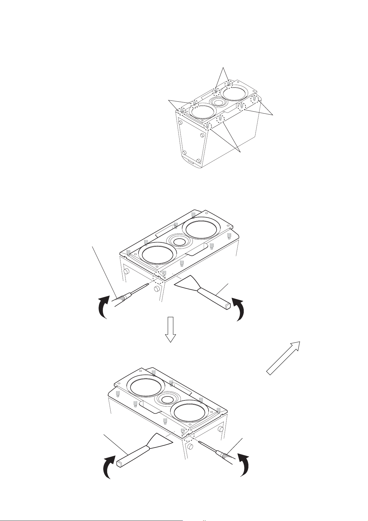
DISASSEMBLY OF SS-FL7
Note 1: Remove the front panel assy by paying attention particulaly
to the periphyery of eight bosses
where the front panel assy bonded tightly.
Note 2: Take care not to damage the set
by applying an excessive force.
Note: Follow the disassembly procedure in the numerical order given.
boss
boss
bos
boss
1
Insert a flat-tip screwdriver into a recess
in the bottom of the set
to raise the front panel assy a little.
2
Insert the jig (J-2051-238-A) into a space
made by inserting the screwdriver,
and raise the front panel assy gradually.
2
Insert the jig (J-2051-238-A) into a space
made by inserting the screwdriver,
and raise the front panel assy gradually.
1
Insert a flat-tip screwdriver into a recess
in the bottom of the set
to raise the front panel assy a little.
2
SS-CT7/FL7/FL7RC/RS7
5
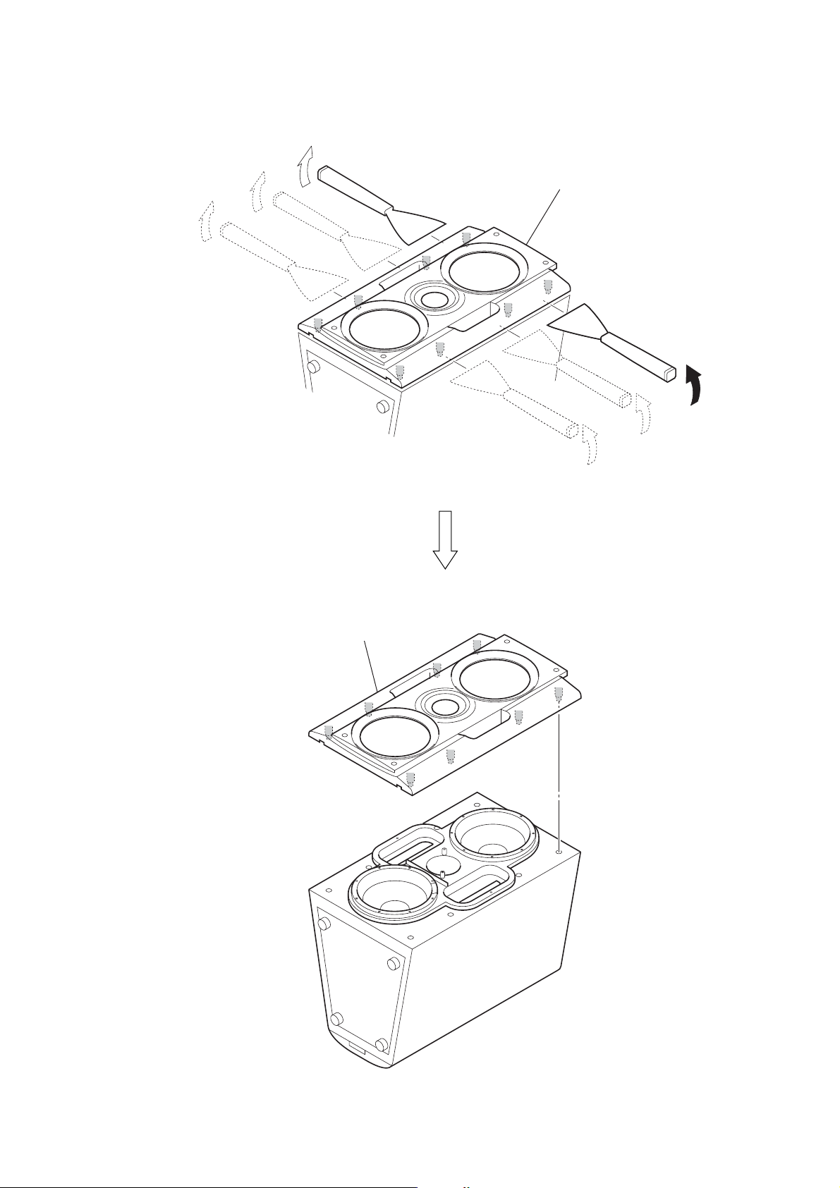
Raise the front panel assy a little by little
from bottom to top of the set.
Ver 1.1
6
front panel assy
3
 Loading...