

Page 1
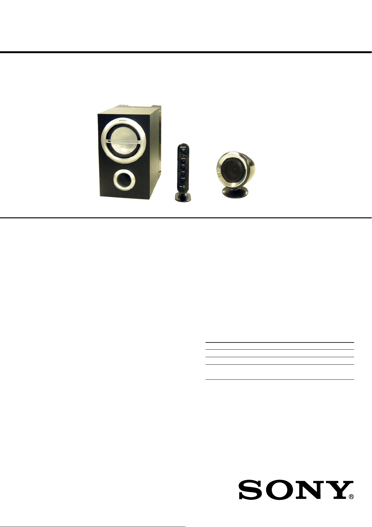
SRS-D511
SERVICE MANUAL
Ver. 1.1 2005. 07
Subwoofer
Speaker section
Satellite speaker
Satellite system Full range, magnetically shielded
Speaker units 5.7 cm, cone type
Enclosure type Closed type
Impedance 4 Ω
Cord length 2 m (for front L and front R speakers)
3 m (for rear L, rear R and center speakers)
Subwoofer
Speaker system Woofer
Speaker units 12 cm, cone type
Enclosure type Bass reflex
Impedance 8 Ω
Amplifier section
Rated output 5W (10% T.H.D., 1 KHz, 4Ω)
(Satellite speaker)
25 W (10% T.H.D., 100 KHz, 8 Ω)
(Subwoofer)
Input Stereo mini jack x 3
(INPUT 1 for 5.1 channel signal input)
Stereo mini jack x 1
(INPUT 2 for 2 channel signal input)
Input impedance 4.7 kΩ (at 1 kHz)
Output Stereo mni jack x 1 (PHONES)
Control Box
SPECIFICATIONS
US Model
Canadian Model
AEP Model
UK Model
E Model
Satellite
Speaker
General
Dimensions (w/h/d) Approx. 50 x 178 x 99 mm (2 x 7 1/8 x 4 in.)
(Controller)
Approx. 98 x 124 x 84 mm (3 7/8 x 5 x 3 3/8 in.)
(Satellite speaker, on a desk)
Approx. 98 x 98 x 83 mm (3 7/8 x 3 7/8 x 3 3/8 in.)
(Satellite speaker, attached to a wall)
Approx. 163 x 267 x 301 mm
(6 1/2 x 10 5/8 x 11 7/8 in.) (Subwoofer)
Mass Approx. 199 g (7 oz.) (Controller)
Approx. 294 g (10 oz.) (Satellite speaker)
Approx. 4.8 kg (10 lb. 9 oz.) (Subwoofer)
Cord length 2 m (Controller to Subwoofer)
2 m (Power cord)
Power consumptions 33 W
Power requirements
Where purchased Operating voltage
U.S.A./Canada 120 V AC, 60Hz
European countries 220 - 230 V AC, 50Hz
Other countries • 120 V AC, 60Hz
• 220 - 230 V AC, 50Hz
Supplied accessories
Connecting Cable (for 5.1 channel signal input)
9-879-507-02
2005G02-1
© 2005.07
Design and specifications are subject to change without notice.
ACTIVE SPEAKER SYSTEM
Sony Corporation
Personal Audio Group
Published by Sony Engineering Corporation
Page 2
SRS-D511
SAFETY CHECK-OUT
After correcting the original service problem, perform the following
safety checks before releasing the set to the customer:
Check the antenna terminals, metal trim, “metallized” knobs, screws,
and all other exposed metal parts for AC leakage. Check leakage as
described below.
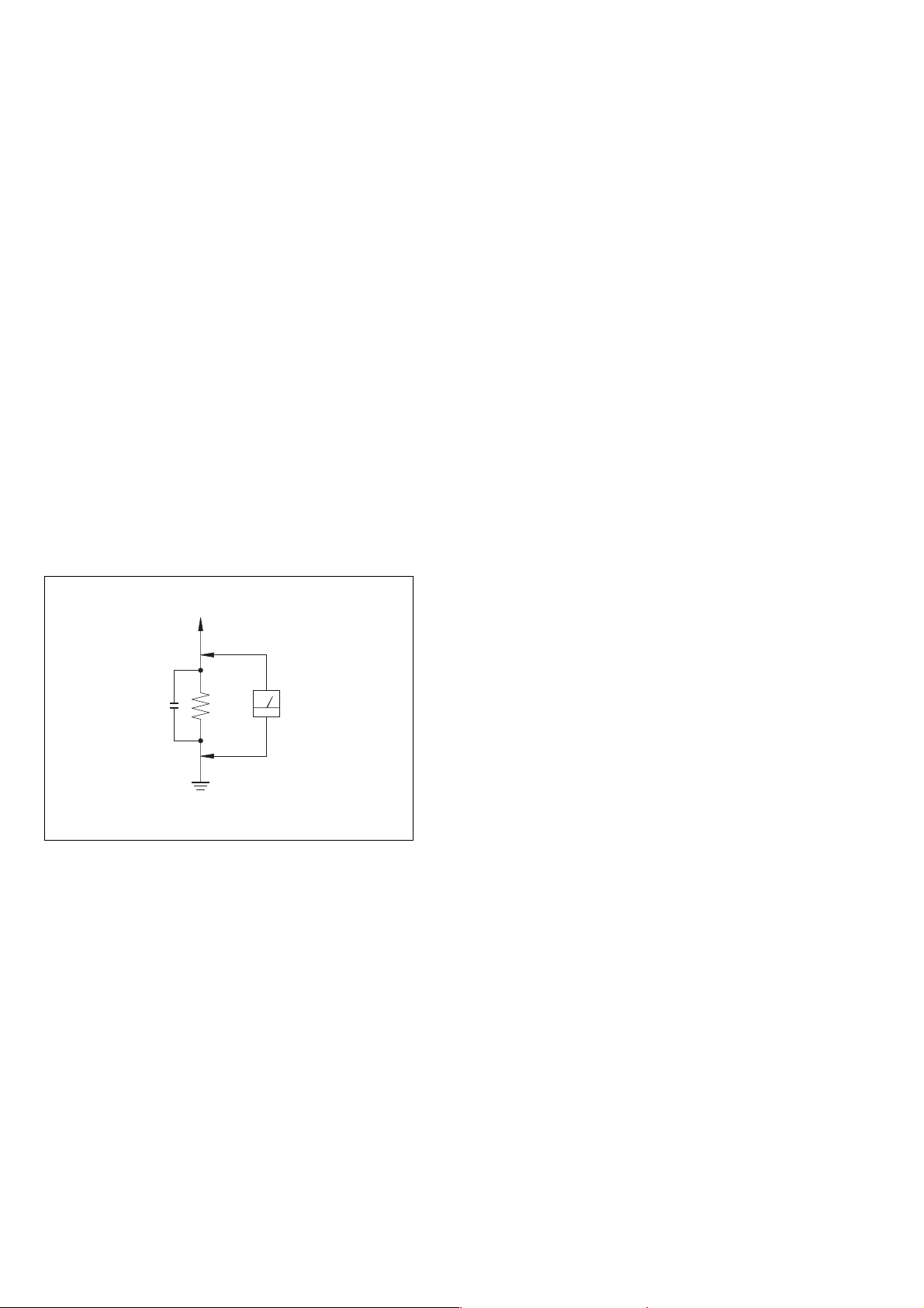
LEAKAGE
The AC leakage from any exposed metal part to earth Ground and
from all exposed metal parts to any exposed metal part having a
return to chassis, must not exceed 0.5 mA (500 microampers).
Leakage current can be measured by any one of three methods.
1. A commercial leakage tester, such as the Simpson 229 or RCA
WT-540A. Follow the manufacturers’ instructions to use these
instruments.
2. A battery-operated AC milliammeter. The Data Precision 245
digital multimeter is suitable for this job.
3. Measuring the voltage drop across a resistor by means of a
VOM or battery-operated AC voltmeter. The “limit” indication
is 0.75 V, so analog meters must have an accurate low-voltage
scale. The Simpson 250 and Sanwa SH-63Trd are examples
of a passive VOM that is suitable. Nearly all battery operated
digital multimeters that have a 2V AC range are suitable. (See
Fig. A)
TABLE OF CONTENTS
Specifications ............................................................................ 1
1. GENERAL ................................................................... 3
2. DIAGRAMS
2-1. Schematic Diagram – Amp Section–............................... 4
2-2. Printed Wiring Boards– Amp Section – .......................... 5
2-3. Schematic Diagram – Control Section– .......................... 6
2-4. Printed Wiring Boards – Control Section–...................... 7
3. EXPLODED VIEWS
3-1. Subwoofer Section .......................................................... 8
3-2. Control Box, Satellite Speaker Section ........................... 9
4. ELECTRICAL PARTS LIST .................................. 10
To Exposed Metal
Par ts on Set
AC
0.15 µF
Fig. A. Using an AC voltmeter to check AC leakage.
1.5 kΩ
Earth Ground
Voltmeter
(0.75 V)
SAFETY-RELATED COMPONENT WARNING!!
COMPONENTS IDENTIFIED BY MARK 0 OR DOTTED LINE
WITH MARK 0 ON THE SCHEMATIC DIAGRAMS AND IN THE
PA RTS LIST ARE CRITICAL TO SAFE OPERATION. REPLACE
THESE COMPONENTS WITH SONY PARTS WHOSE PART
NUMBERS APPEAR AS SHOWN IN THIS MANUAL OR IN
SUPPLEMENTS PUBLISHED BY SONY.
2
ATTENTION AU COMPOSANT AYANT RAPPORT
À LA SÉCURITÉ!!
LES COMPOSANTS IDENTIFIÉS PAR UNE MARQUE 0 SUR LES
DIAGRAMMES SCHÉMATIQUES ET LA LISTE DES PIÈCES
SONT CRITIQUES POUR LA SÉCURITÉ DE FONCTIONNEMENT.
NE REMPLACER CES COMPOSANTS QUE PAR DES PIÈCES
SONY DONT LES NUMÉROS SONT DONNÉS DANS CE MANUEL
OU DANS LES SUPPLÉMENTS PUBLIÉS PAR SONY.
Page 3
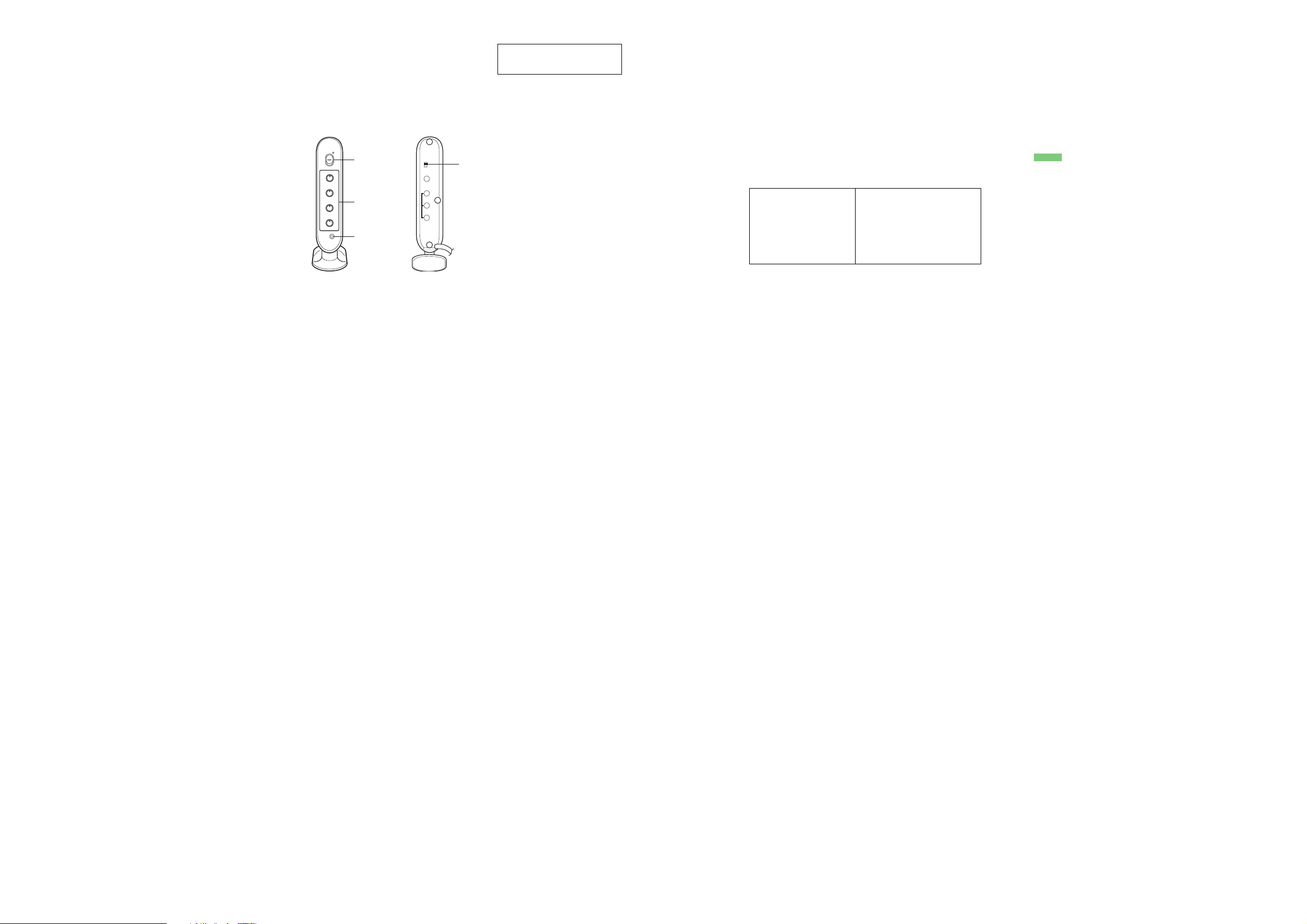
LOCATING THE CONTROLS
VOLUME: Controls total volume level.
BASS: Adjusts bass level (Subwoofer).
REAR: Adjusts rear surround sound (Rear Speaker).
CENTER: Adjusts center speaker level as necessary to
make balanced sound.
PHONES: Connect the headphones for personal
listening.
SECTION 1
GENERAL
POWER
ON
OFF
VOLUME
MIN MAX
BASS
MIN MAX
REAR
MIN MAX
CENTER
MIN MAX
PHONES
Controller (Front)
DUAL STEREO
POWER
VOLUME
ON
OFF
INPUT 2
INPUT 1
FRONT
REAR
CENTER
SUBWOOFER
DUAL SPEAKER
PHONES
Controller (Rear)
DUAL STEREO: Switches a 4 channel or 2 channel
source to 5.1 channel.
This section is extracted
from instruction manual.
SECTION 2
DIAGRAMS
THIS NOTE IS COMMON FOR PRINTED WIRING BOARDS AND SCHEMATIC DIAGRAMS.
(In addition to this necessary note is printed in each block.)
For schematic diagrams.
Note:
• All capacitors are in µF unless otherwise noted. (p: pF) 50 WV or
less are not indicated except for electrolytics and tantalums.
• All resistors are in Ω and 1/
• C : panel designation.
Note:
The components identified by mark 0 or dotted
line with mark 0 are criti-
cal for safety.
Replace only with part
number specified.
4
W or less unless otherwise specified.
Note:
Les composants identifiés par
une marque 0 sont critiques
pour la sécurité.
Ne les remplacer que par une
piéce portant le numéro
spécifié.
• A : B+ Line.
• B : B– Line.
•Voltages are dc with respect to ground under no-signal conditions.
• no mark : Power on
•Voltages are taken with a VOM (Input impedance 10 MΩ).
Voltage variations may be noted due to normal production tolerances.
• Signal path.
F : AUDIO
• Abbreviation
CND : Canadian model
SP : Singapore model
KR : Korean model
C&SA : Central & South America
For printed wiring boards.
Note:
• X : parts extracted from the component side.
• : Pattern from the side which enables seeing.
• Abbreviation
CND : Canadian model
SP : Singapore model
KR : Korean model
C&SA : Central & South America
SRS-D511
Ver. 1.1
SRS-D511
33
Page 4
SRS-D511
Ver. 1.1
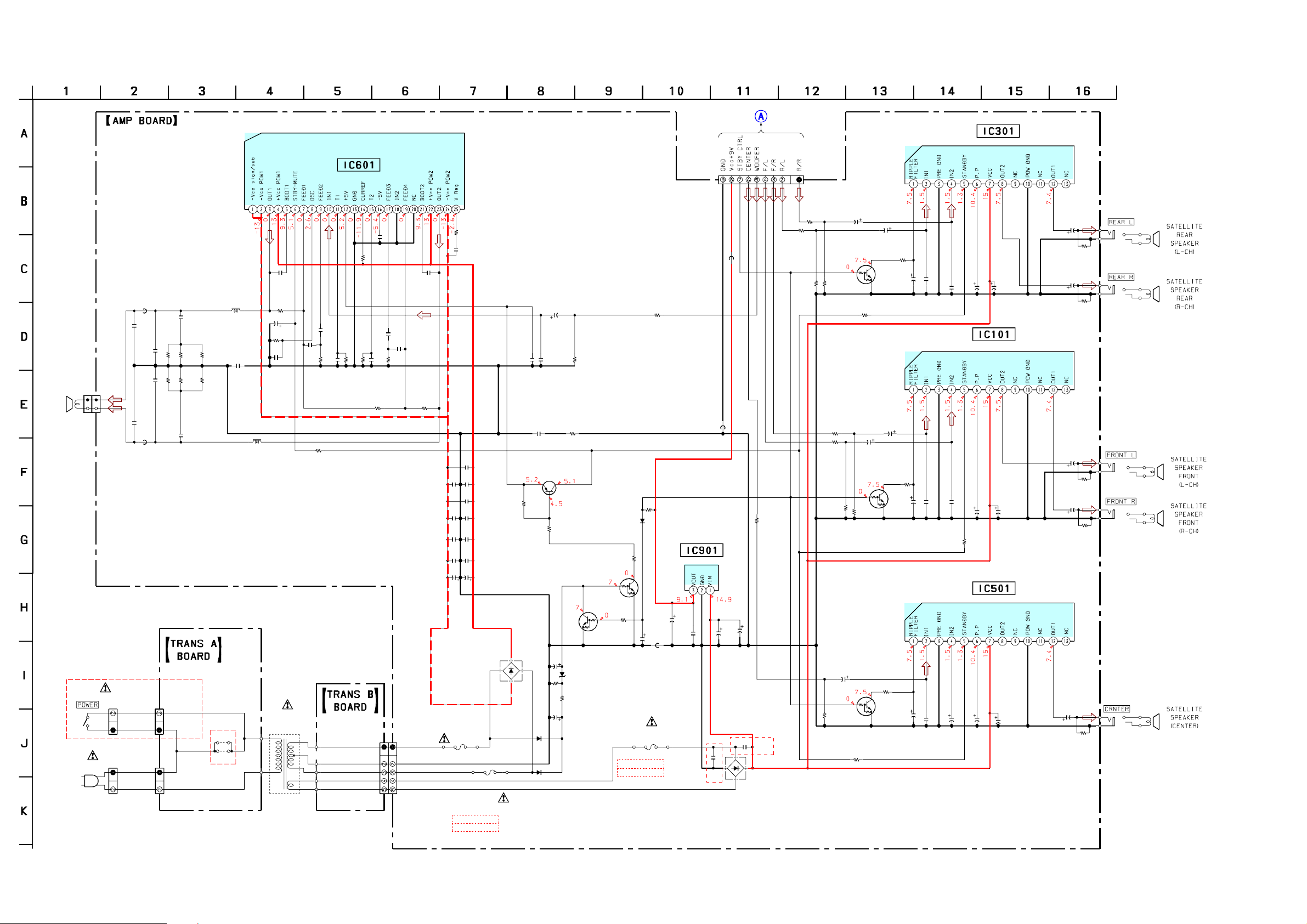
2-1. SCHEMATIC DIAGRAM – AMP SECTION –
2P
2P
C670
560p
R664
330
R667
330
C671
560p
AEP,UK,SP,KR
R663
330
R666
330
R662
330
R665
330
US,CND, C&SA
901
JW
JW902
L601
33mH
C669
0.01
C654
4.7
50V
R652
10k
SPEAKER
(SUB WOOFER)
AC901
AC IN
CNP601
2P
S901
CN601
2P
CNP902
2P
FB672
1.1uH
C680
1000p
C672
0.68
C673
0.68
C681
1000p
FB673
1.1uH
CN902
CN901
L602
33mH
C650
0.033
R650
51k
C656
24p
T901
POWER
TRANSFORMER
C655
470p
R653
R651
30k
CONTROL
BOARD
(Page6)
C451
C151
R155
4.7k
C556
50V
POWER AMP
IC301
LA4631
C352
470
16V
R356
1k
C452
C153
C253
C552
470
16V
470
16V
470
16V
470
16V
R456
R156
R256
R556
1k
1k
1k
1k
C355
1000
25V
C354
4.7
50V
POWER AMP
IC101
LA4631
C156
1000
4.7
50V
IC501
LA4631
POWER AMP
4.7
50V
25V
C555
1000
25V
C155
C554
1
J108
J109
J106
J107
J110
IC601
TDA7490L
CN101
R350
3.3k
R352
1k
R450
3.3k
9P
DTC144EUA
R452
1k
R251
4.7k
R151
4.7k
R152
470
R552
1k
C450
50V
Q354
STANDBY
R252
470
C550
10
DTC144EUA
50V
R555
4.7k
10
R355
4.7k
C150
10
50V
DTC144EUA
STANDBY
Q554
STANDBY
Q154
C350
10
50V
R554
220
C250
10
50V
R354
C353
100
16V
C154
C553
100
16V
220
R154
220
100
16V
C351
0.001
C251
0.001
C551
0.001
0.001
0.001
ER AMP
POW
R660
6.8
C674
0.1
C653
0.1
C912
2200p
C908
0.1
C902
2200
35V
FH905
C668
0.1
D1002
D3SBA20-4100
F903
*1
FH906
FH907
*1 F903,904
2.5A/125V
2.5A/250V
C651
0.1
C675
0.1
C667
0.1
C652
0.1
C911
2200p
C907
0.1
C901
2200
35V
F904
*1
C661
0.1
R56
10k
FH908
US,CND,C&SA
AEP,UK,SP,KR
C684
1000p
2SA1586
C659
0.001
Q55
MUTE
C658
0.33
50V
R52
47k
R57
10k
R671
2.2k
R684
10
DTC144EUA
AC DETECT
C52
0.1
50V
D55
UDZ-TE-17-8.2B
R51
1k
C51
2.2
50V
D51
1SS355TE-17
D52
1SS355TE-17
1SS355TE-17
Q51
DTC144EUA
STANDBY
Q56
D53
R58
10k
R59
47k
FH901
*2 F901
5A/125V
5A/250V
C59
4.7
50V
F901
R661
2.2k
FB904
*2
R66
1k
C910
47
16V
C909
0.01
FH902
US,CND,C&SA
AEP,UK,SP,KR
FB906
IC901
KIA78S09
+9V REG.
AEP,UK,SP,KR
FB905
C959
0.047
C905
1000
25V
R550
2.2k
C903
4700
25V
AEP,UK,SP,KR
C960
0.047
D1001
D3SBA20-4100
C663
0.1
R655
130k
C657
470p
R654
R656
22k
22k
C660
330p
68k
C662
330p
CN904
5P
R658
4.7k
R657
68k
C664
470p
CNP904
5P
C665
470p
C666
0.033
R659
51k
SRS-D511
44
Page 5
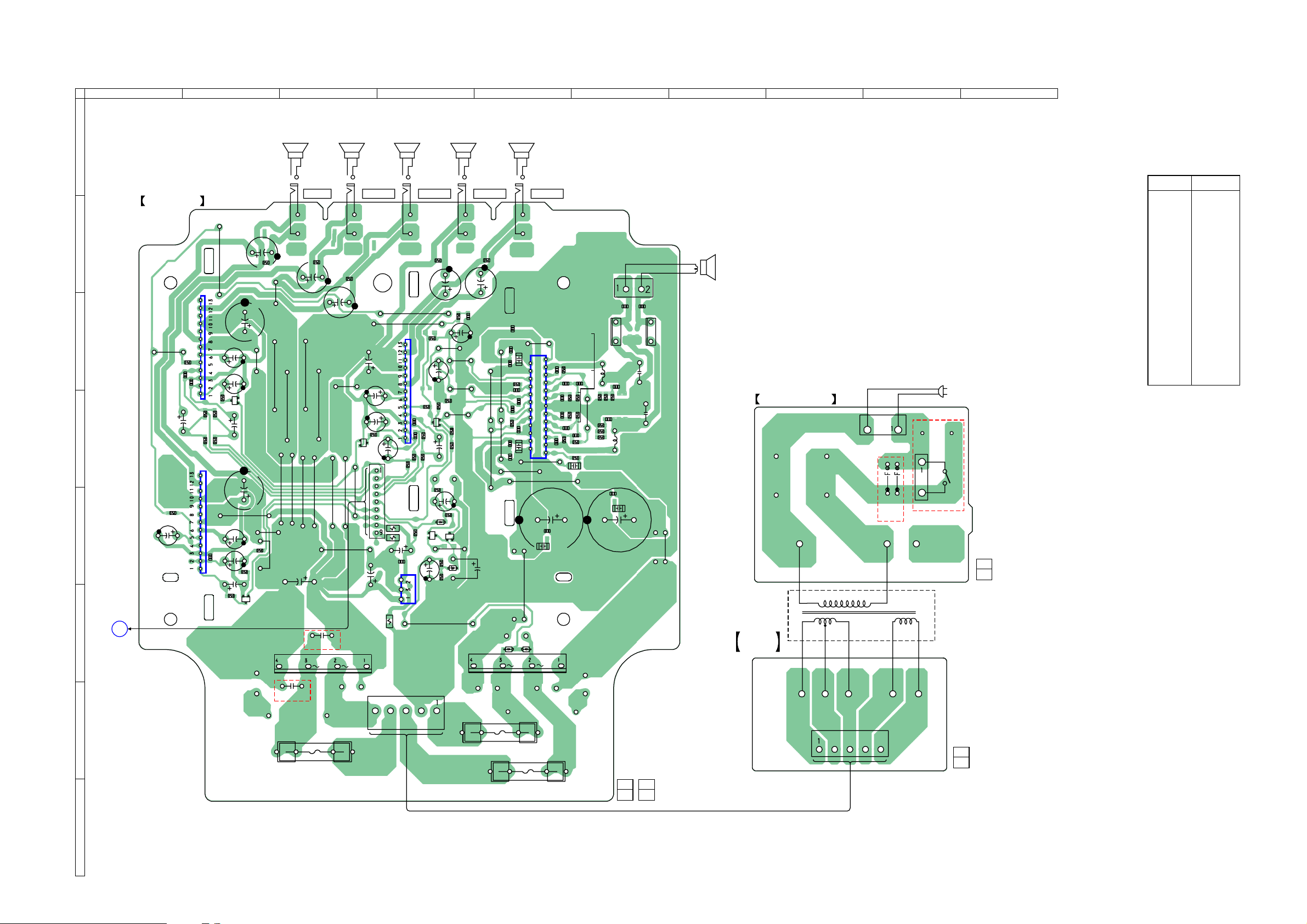
2-2. PRINTED WIRING BOARD – AMP SECTION –
SRS-D511
Ver. 1.1
1
2
SATELLITE
SPEAKER
(CENTER)
3 4 5 6 7
SATELLITE
SPEAKER
REAR
(R-CH)
SATELLITE
SPEAKER
REAR
(L-CH)
SATELLITE
SPEAKER
FRONT
(R-CH)
SATELLITE
SPEAKER
FRONT
(L-CH)
8
9 10
A
• Semiconductor
Location
J110
J109
J108
J107
BOARDAMP
B
IC301
C
JW86
R355
C451
C351
C450
D
R452
R450
C354
R354
R352
R350
IC501
R555
C556
E
C551
C550
C553
R554
F
G
A
CONTROL
BOARD
(Page 7)
JW83
C554
E
C350
C555
E
Q554
Q354
C552
R556
C355
JW85
C353
JW56
JW97
R550
R552
AEP,UK,SP,KR
C452
JW84
JW94
JW92
JW93
JW91
JW90
JW57
JW55
C903
–
C959
AEP,UK,SP,KR
FH902
R456
JW58
C960
JW95
F901
C352
JW59
JW54
R356
JW62
Q154
JW60
TP924
FH901
C156
C155
C154
R154
E
JW61
C905
D1001
+
C250
CN101
FB905
C910
IC901
FB904
TP923
FB906
C909
CNP904
JW96
JW63
R251
R256
R651
C658
IC101
R155
C151
Q55
C251
R252
R151
D53
R66
E
C51
C253
R152
Q56
R51
JW52
JW98
R661
E
C150
R58
R52
JW64
TP608
JW65
R671
JW66
R57
R59
Q51
E
R684
R56
C59
D55
FH905
C153
C684
C654
JW53
FH907
R156
C52
–
D51
F903
C669
C674
JW69
C656
JW70
C653
C675
R652
C661
R655
C652
D1002
C651
JW74
F904
JW82
C659
C663
C667
C912
JW77
FRONT LFRONT RREAR LREAR RCENTER
2
24
D52
25
JW73
J106
1
C657
IC601
JW75
C902
C908
+
FH906
C650
C666
R650
R659
CN601
FB672
R653
R654
C660
R657
C662
R656
C655
JW81
C664
C665
R658
R660
C668
TP902
FH908
1-865-417-
C671
R666
R665
R667
C680
L601
C670
L602
C911
11
(11)
C907
C901
R664
R663
12
(12)
C681
C672
R662
C673
FB673
JW80
SPEAKER
(SUB WOOFER)
TRANS B
BOARD
BOARDTRANS A
CN904
CN901
JW902
JW901
US,CND,C&SA
CN902
(POWER)
AEP,UK,SP,KR
1-865-419-
1-865-420-
AC IN
S901
T901
POWER
TRANSFORMER
11
(11)
Ref. No. Location
D51 F-5
D52 F-5
D53 E-4
D55 E-4
D1001 F-3
D1002 F-5
IC101 C-4
IC301 C-2
IC501 E-2
IC601 D-5
IC901 F-4
Q51 E-4
Q55 D-4
Q56 E-4
Q154 D-3
Q354 D-2
Q554 F-2
11
(11)
SRS-D511
H
55
Page 6

SRS-D511
Ver. 1.1
2-3. SCHEMATIC DIAGRAM – CONTROL SECTION –
J101
J103
J102
J104
FB501
0
FB801
0
FB601
0
FB301
0
FB802
0
FB401
0
FB101
0
FB803
0
FB201
0
FB804
0
C1
10
FB202
0
FB102
0
R101
1k
R201
1k
R501
1k
0.0022
R601
0.0068
1k
R301
1k
0.0022
R401
1k
0.0022
0.0022
0.0022
R2
R1
1k
1k
C3
C2
10
10
C502
C602
C302
C402
C102
C202
C501
4.7
50V
C601
4.7
50V
C301
4.7
50V
C401
4.7
50V
C101
4.7
50V
C201
4.7
50V
R502
47k
R602
47k
R302
47k
R402
47k
R102
47k
R202
47k
R6
10k
OFF
ON
S701
D703
C609
1000p
1SS355TE-17
R720
10
R721
10
C109
1000p
1000p
C720
47
16V
C209
R705
0
Q706
DTC343TK-T-146
UTE
M
FB703
Q705
DTC343TK-T-146
MUTE
C309
C409
1000p
1000p
FB704
0
C716
100p
0
R703
1k
D701
SLC-22MG3F
ON
R12
100
C107
100p
C207
100p
RV1
10k
R10
4.7k
R11
4.7k
1
SW
OFF
R509
0
R309
0
R5
10k
R14
10k
IC1
C106
100p
C206
100p
C702
0.1
Q703
KRA107S
+B SWITCH
R704
100k
C703
47
16V
C406
100p
C203
0
NJM4580E-TE2
C103
0
C403
0
IC801
LPF
IC802
PRE AMP
C404
C104
0
C204
0
C806
220
16V
0
R204
47k
R404
47k
C805
0.1
R104
47k
R805
4.7k
R406
1.5k
R206
3.3k
R205
10k
R106
3.3k
R405
4.7k
R105
10k
R808
4.7k
C802
100
16V
C801
R724
1k
C712
R722
100
4.7k
16V
C713
R723
100
4.7k
16V
0.1
C803
0.1
R407
100
R107
100
R207
100
1000p
C105
4.7
50V
C205
4.7
50V
C405
C509
4.7
50V
FB701
FB702
0
0
C717
220
16V
C722
0.1
C721
0.1
FB119
FB118
FB117
FB116
FB115
FB111
FB112
FB113
FB114
J701
C718
0.001
C719
0.01
0
0
0
0
0
0
0
0
0
CN1
9P
AMP
BOARD
(Page4)
SRS-D511
PRE AM
R603
10k
C306
100p
C303
C503
C304
0
0
IC803
PRE AMP
R604
10k
0
C504
R608
100k
0
R504
47k
R304
47k
C606
2200p
R506
1.5k
R505
4.7k
R606
4.7k
R305
4.7k
R306
1.5k
R605
220k
C804
C604
0.047
0.1
P
R8
5.6k
C5
100
C4
0.1
16V
RV601
10k
RV301
10k/10k
RV501
10k
R307
100
R507
100
R607
100
C305
4.7
50V
C505
4.7
50V
C605
0.47
50V
66
Page 7

2-4. PRINTED WIRING BOARD – CONTROL SECTION –
1
2
3 4 5
BOARDCONTROL
SRS-D511
C4
JW16
R808
C205
R10
R12
5
JW
C201
R401
C716
R8
JW3
JW4
R601
C805
C802
C717
C109
C209
C309
C409
R602
R309
C101
FB202
FB201
C401
FB401
C601
C719
JW23
IC1
R14
R509
R502
C3
R201
R2
C402
C602
FB601
FB119
FB118
FB111
FB112
FB113
FB114
R11
R402
R302
R202
R102
C102
C202
C502
CN1
1-865-418-
SW1
C1
FB803
C301
C302
FB802
C501
FB801
R5
R6
FB102
FB804
R1
R501
C718
FB115
C2
R101
FB101
R301
FB301
FB501
FB117
FB116
C509
C609
24
JW
SW
DUAL STEREO
ON
t
OFF
A
AMP
BOARD
(Page 5)
11
(11)
1
J104
INPUT 2
J103
FRONT
J102
REAR
J101
CENTER/SUBWOOFER
INPUT 1
A
S701
POWER
OFF
t
ON
B
RV1
VOLUME
C
RV601
BASS
D
E
RV301
REAR
RV501
CENTER
J701
PHONE
F
C722
C720
D703
RV301
RV501
D701
R603
FB702
C721
S701
RV601
28
JW
C403
R604
C606
R705
FB704
FB703
R703
C702
R704
R724
RV1
C503
FB701
C406
C504
Q706
E
R104
C203
C306
R404
R608
R606
R504
R506
C103
C104
C204
C304
R304
C303
C404
IC803
R505
E
Q705
R204
R406
R721
R306
C408
R605
R723
C703
JW10
JW11
JW12
C207
C206
IC801
R206
IC802
R305
R405
C604
R607
R507
R720
R722
R106
C804
C713
C106
R105
R205
R407
C712
9
JW
C107
R307
C803
C405
C505
C5
8
JW
C801
C605
JW21
JW22
JW25
7
JW
C305
JW26
R207
6
JW
JW14
JW15
JW17
JW18
JW19
JW20
R805
C806
Q703
E
R107
C105
• Semiconductor
Location
Ref. No. Location
D701 A-2
D703 B-2
IC1 A-3
IC801 C-2
IC802 D-2
IC803 E-2
Q703 E-3
Q705 F-2
Q706 E-2
7
Page 8

SRS-D511
Ver. 1.1
NOTE:
• -XX, -X mean standardized parts, so they may
have some differences from the original one.
• Items marked “*” are not stocked since they
are seldom required for routine service. Some
delay should be anticipated when ordering these
items.
• The mechanical parts with no reference number
in the exploded views are not supplied.
3-1. SUBWOOFER SECTION
3
SECTION 3
EXPLODED VIEWS
• Accessories are given in the last of this parts
list.
• Abbreviation
CND : Canadian model
SP : Singapore model
KR : Korean model
C&SA : Central & South America
The components identified by mark 0 or
dotted line with mark 0 are critical for
safety.
Replace only with part number specified.
Les composants identifiés par une
marque 0 sont critiques pour la sécurité.
Ne les remplacer que par une pièce
portant le numéro spécifié.
7
9
2
S901
2
7
not supplied
6
5
8
1
4
T901
7
Ref. No. Part No. Description Remarks
1 X-2055-164-1 CABINET, MAIN SUB ASSY (US, CND, C&SA)
1 X-2055-397-1 CABINET, MAIN SUB ASSY (AEP, UK, SP, KR)
2 3-254-144-11 SCREW (B3), (+) BV TAPPING
3 A-1092-397-A AMP BOARD, COMPLETE (US, CND, C&SA)
3 A-1108-815-A AMP BOARD, COMPLETE (AEP, UK, SP, KR)
4 A-1104-248-A TRANS A BOARD, COMPLETE (US, CND, C&SA)
4 A-1113-981-A TRANS A BOARD, COMPLETE (AEP, UK, SP, KR)
5 2-102-924-01 BRACKET, CORD
* 6 3-703-244-00 BUSHING (2104), CORD
7 3-252-829-01 SCREW (B3), (+) BV TAPPING
8
Ref. No. Part No. Description Remarks
8 2-345-700-11 CABINET (W), REAR (US, CND)
8 2-345-700-31 CABINET (W), REAR (AEP, UK)
8 2-345-700-51 CABINET (W), REAR (SP, KR)
8 2-345-700-71 CABINET (W), REAR (C&SA)
0 9 1-769-079-23 CORD, POWER (KR)
0 9 1-777-071-23 CORD, POWER (AEP, UK, SP)
0 9 1-783-820-11 CORD, POWER (US, CND, C&SA)
0 S901 1-762-876-11 SWITCH, AC POWER (AEP, UK, SP, KR)
0 T901 1-443-656-11 TRANSFORMER, POWER (US, CND, C&SA)
0 T901 1-443-697-11 TRANSFORMER, POWER (AEP, UK, SP, KR)
Page 9

3-2. CONTROL BOX, SATELLITE SPEAKER SECTION
55
53
52
SRS-D511
Ver. 1.1
51
58
59
54
57
57
56
63
62
60
61
Ref. No. Part No. Description Remarks Ref. No. Part No. Description Remarks
51 2-345-704-01 KNOB, POWER
52 2-541-579-01 CABINET (C), FRONT (US, CND, C&SA)
52 2-541-579-11 CABINET (C), FRONT (AEP, UK, SP, KR)
53 1-830-410-11 CABLE 9P
54 2-345-705-01 KNOB, VOLUME
55 A-1103-108-A CONTROL BOARD, COMPLETE (US, CND, C&SA)
55 A-1134-415-A CONTROL BOARD, COMPLETE (AEP, UK, SP, KR)
56 2-541-580-01 CABINET (C), REAR
57 3-252-829-01 SCREW (B3), (+) BV TAPPING
58 X-2055-167-1 CABINET (S) FRONT SUB ASSY
59 1-826-096-11 SPEAKER (57mm)
60 2-345-693-01 CABINET (S), REAR
61 2-345-695-01 STAND
62 3-253-143-01 SCREW (B2.6), (+) P TAPPING
63 1-830-408-11 CABLE, MONO (for FRONT L/R-CH)
63 1-830-408-21 CABLE, MONO (for REAR L/R and CENTER-CH)
9
Page 10

SRS-D511
Ver. 1.1
AMP
NOTE:
• Due to standardization, replacements in the
parts list may be different from the parts
specified in the diagrams or the components
used on the set.
• -XX, -X mean standardized parts, so they
may have some difference from the original
one.
• Items marked “*” are not stocked since they
are seldom required for routine service.
Some delay should be anticipated when
ordering these items.
• CAPACITORS:
uF: µF
SECTION 4
ELECTRICAL PARTS LIST
• RESISTORS
All resistors are in ohms.
METAL: metal-film resistor
METAL OXIDE: Metal Oxide-film resistor
F: nonflammable
• COILS
uH: µH
•SEMICONDUCTORS
In each case, u: µ, for example:
uA...: µA... , uPA... , µPA... ,
uPB... , µPB... , uPC... , µPC... ,
uPD..., µPD...
• Abbreviation
CND : Canadian model
SP : Singapore model
KR : Korean model
C&SA : Central & South America
The components identified by mark 0
or dotted line with mark 0 are critical
for safety.
Replace only with part number specified.
Les composants identifiés par une
marque 0 sont critiques pour la sécurité.
Ne les remplacer que par une pièce
portant le numéro spécifié.
When indicating parts by reference
number, please include the board.
Ref. No. Part No. Description Remarks Ref. No. Part No. Description Remarks
C51 1-126-961-11 ELECT 2.2uF 20% 50V
C52 1-126-956-91 ELECT 0.1uF 20% 50V
C59 1-126-963-11 ELECT 4.7uF 20% 50V
C150 1-126-964-11 ELECT 10uF 20% 50V
C151 1-162-964-11 CERAMIC CHIP 0.001uF 10% 50V
C153 1-126-935-11 ELECT 470uF 20% 16V
C154 1-126-933-11 ELECT 100uF 20% 16V
C155 1-126-963-11 ELECT 4.7uF 20% 50V
C156 1-126-942-61 ELECT 1000uF 20% 25V
C250 1-126-964-11 ELECT 10uF 20% 50V
C251 1-162-964-11 CERAMIC CHIP 0.001uF 10% 50V
C253 1-126-935-11 ELECT 470uF 20% 16V
C350 1-126-964-11 ELECT 10uF 20% 50V
C351 1-162-964-11 CERAMIC CHIP 0.001uF 10% 50V
C352 1-126-935-11 ELECT 470uF 20% 16V
C353 1-126-933-11 ELECT 100uF 20% 16V
C354 1-126-963-11 ELECT 4.7uF 20% 50V
C355 1-126-942-61 ELECT 1000uF 20% 25V
C450 1-126-964-11 ELECT 10uF 20% 50V
C451 1-162-964-11 CERAMIC CHIP 0.001uF 10% 50V
C452 1-126-935-11 ELECT 470uF 20% 16V
C550 1-126-964-11 ELECT 10uF 20% 50V
C551 1-162-964-11 CERAMIC CHIP 0.001uF 10% 50V
C552 1-126-935-11 ELECT 470uF 20% 16V
C553 1-126-933-11 ELECT 100uF 20% 16V
C554 1-126-963-11 ELECT 4.7uF 20% 50V
C555 1-126-942-61 ELECT 1000uF 20% 25V
C556 1-126-960-11 ELECT 1uF 20% 50V
C650 1-100-436-91 CERAMIC CHIP 0.033uF 10% 25V
C651 1-115-339-11 CERAMIC CHIP 0.1uF 10% 50V
C652 1-100-566-91 CERAMIC CHIP 0.1uF 10% 25V
C653 1-100-566-91 CERAMIC CHIP 0.1uF 10% 25V
C654 1-126-963-11 ELECT 4.7uF 20% 50V
C655 1-162-962-11 CERAMIC CHIP 470PF 10% 50V
C656 1-162-975-11 CERAMIC CHIP 24PF 5% 50V
C657 1-162-962-11 CERAMIC CHIP 470PF 10% 50V
C658 1-124-252-00 ELECT 0.33uF 20% 50V
C659 1-162-964-11 CERAMIC CHIP 0.001uF 10% 50V
A-1092-397-A AMP BOARD, COMPLETE (US, CND, C&SA)
A-1108-815-A AMP BOARD, COMPLETE (AEP, UK, SP, KR)
*********************
3-252-833-01 SCREW (M3), (+) P
< CAPACITOR >
C660 1-162-961-11 CERAMIC CHIP 330PF 10% 50V
C661 1-107-826-11 CERAMIC CHIP 0.1uF 10% 16V
C662 1-162-961-11 CERAMIC CHIP 330PF 10% 50V
C663 1-107-826-11 CERAMIC CHIP 0.1uF 10% 16V
C664 1-162-962-11 CERAMIC CHIP 470PF 10% 50V
C665 1-162-962-11 CERAMIC CHIP 470PF 10% 50V
C666 1-100-436-91 CERAMIC CHIP 0.033uF 10% 25V
C667 1-115-339-11 CERAMIC CHIP 0.1uF 10% 50V
C668 1-115-339-11 CERAMIC CHIP 0.1uF 10% 50V
C669 1-162-970-11 CERAMIC CHIP 0.01uF 10% 25V
C670 1-164-739-11 CERAMIC CHIP 560PF 5% 50V
C671 1-164-739-11 CERAMIC CHIP 560PF 5% 50V
C672 1-131-702-11 FILM 0.68uF 5% 50V
C673 1-131-702-11 FILM 0.68uF 5% 50V
C674 1-100-566-91 CERAMIC CHIP 0.1uF 10% 25V
C675 1-100-566-91 CERAMIC CHIP 0.1uF 10% 25V
C680 1-162-964-11 CERAMIC CHIP 0.001uF 10% 50V
C681 1-162-964-11 CERAMIC CHIP 0.001uF 10% 50V
C684 1-162-964-11 CERAMIC CHIP 0.001uF 10% 50V
C901 1-126-953-11 ELECT 2200uF 20% 35V
C902 1-126-953-11 ELECT 2200uF 20% 35V
C903 1-128-548-11 ELECT 4700uF 20% 25V
C905 1-126-942-61 ELECT 1000uF 20% 25V
C907 1-115-339-11 CERAMIC CHIP 0.1uF 10% 50V
C908 1-115-339-11 CERAMIC CHIP 0.1uF 10% 50V
C909 1-162-970-11 CERAMIC CHIP 0.01uF 10% 25V
C910 1-126-947-11 ELECT 47uF 20% 35V
C911 1-162-966-11 CERAMIC CHIP 0.0022uF 10% 50V
C912 1-162-966-11 CERAMIC CHIP 0.0022uF 10% 50V
C959 1-130-491-00 MYLAR 0.047uF 5% 50V
(AEP, UK, SP, KR)
C960 1-130-491-00 MYLAR 0.047uF 5% 50V
(AEP, UK, SP, KR)
< CONNECTOR >
* CN101 1-564-711-11 PIN, CONNECTOR (SMALL TYPE) 9P
CN601 1-564-320-00 PIN, CONNECTOR (3.96mm PITCH) 2P
< DIODE >
D51 8-719-988-61 DIODE 1SS355TE-17
D52 8-719-988-61 DIODE 1SS355TE-17
D53 8-719-988-61 DIODE 1SS355TE-17
D55 8-719-056-85 DIODE UDZ-TE-17-8.2B
D1001 6-500-385-01 DIODE D3SBA20-4100
10
Page 11

SRS-D511
Ver. 1.1
AMP CONTROL
Ref. No. Part No. Description Remarks Ref. No. Part No. Description Remarks
D1002 6-500-385-01 DIODE D3SBA20-4100
< FUSE >
0 F901 1-532-505-33 FUSE (T5AL/250V) (AEP, UK, SP, KR)
0 F901 1-533-420-12 FUSE, GLASS CYLINDRICAL(DIA.5)
(T5AL/125V) (US, CND, C&SA)
0 F903 1-532-464-33 FUSE (T2.5AL/250V) (AEP, UK, SP, KR)
0 F903 1-533-418-12 FUSE (T2.5AL/125V) (US, CND, C&SA)
0 F904 1-532-464-33 FUSE (T2.5AL/250V) (AEP, UK, SP, KR)
0 F904 1-533-418-12 FUSE (T2.5AL/125V) (US, CND, C&SA)
< FERRITE BEAD >
FB672 1-410-397-21 FERRITE 1.1uH
FB673 1-410-397-21 FERRITE 1.1uH
FB904 1-414-232-22 INDUCTOR, FERRITE BEAD
FB905 1-414-232-22 INDUCTOR, FERRITE BEAD
FB906 1-414-232-22 INDUCTOR, FERRITE BEAD
< FUSE HOLDER >
FH901 1-533-313-11 FUSE HOLDER
FH902 1-533-313-11 FUSE HOLDER
FH905 1-533-313-11 FUSE HOLDER
FH906 1-533-313-11 FUSE HOLDER
FH907 1-533-313-11 FUSE HOLDER
FH908 1-533-313-11 FUSE HOLDER
< IC >
IC101 6-706-641-01 IC LA4631-E
IC301 6-706-641-01 IC LA4631-E
IC501 6-706-641-01 IC LA4631-E
IC601 6-704-237-01 IC TDA7490L
IC901 6-700-776-01 IC KIA78S09P-TP
< JACK >
J106 1-566-822-61 JACK (FRONT L)
J107 1-566-822-61 JACK (FRONT R)
J108 1-566-822-61 JACK (REAR L)
J109 1-566-822-61 JACK (REAR R)
J110 1-566-822-61 JACK (CENTER)
< COIL >
L601 1-400-914-11 FIXED INDUCTOR 33mH
L602 1-400-914-11 FIXED INDUCTOR 33mH
< TRANSISTOR >
Q51 8-729-029-14 TRANSISTOR DTC144EUA-T106
Q55 8-729-230-60 TRANSISTOR 2SA1586-YG
Q56 8-729-029-14 TRANSISTOR DTC144EUA-T106
Q154 8-729-029-14 TRANSISTOR DTC144EUA-T106
Q354 8-729-029-14 TRANSISTOR DTC144EUA-T106
R59 1-216-841-11 METAL CHIP 47K 5% 1/10W
R66 1-216-821-11 METAL CHIP 1K 5% 1/10W
R151 1-216-829-11 METAL CHIP 4.7K 5% 1/10W
R152 1-216-817-11 METAL CHIP 470 5% 1/10W
R154 1-216-813-11 METAL CHIP 220 5% 1/10W
R155 1-216-829-11 METAL CHIP 4.7K 5% 1/10W
R156 1-216-821-11 METAL CHIP 1K 5% 1/10W
R251 1-216-829-11 METAL CHIP 4.7K 5% 1/10W
R252 1-216-817-11 METAL CHIP 470 5% 1/10W
R256 1-216-821-11 METAL CHIP 1K 5% 1/10W
R350 1-216-827-11 METAL CHIP 3.3K 5% 1/10W
R352 1-216-821-11 METAL CHIP 1K 5% 1/10W
R354 1-216-813-11 METAL CHIP 220 5% 1/10W
R355 1-216-829-11 METAL CHIP 4.7K 5% 1/10W
R356 1-216-821-11 METAL CHIP 1K 5% 1/10W
R450 1-216-827-11 METAL CHIP 3.3K 5% 1/10W
R452 1-216-821-11 METAL CHIP 1K 5% 1/10W
R456 1-216-821-11 METAL CHIP 1K 5% 1/10W
R550 1-216-827-11 METAL CHIP 3.3K 5% 1/10W
R552 1-216-821-11 METAL CHIP 1K 5% 1/10W
R554 1-216-813-11 METAL CHIP 220 5% 1/10W
R555 1-216-829-11 METAL CHIP 4.7K 5% 1/10W
R556 1-216-821-11 METAL CHIP 1K 5% 1/10W
R650 1-218-331-11 METAL CHIP 51K 5% 1/10W
R651 1-218-882-11 METAL CHIP 30K 0.5% 1/10W
R652 1-216-833-11 METAL CHIP 10K 5% 1/10W
R653 1-216-843-11 METAL CHIP 68K 5% 1/10W
R654 1-216-837-11 METAL CHIP 22K 5% 1/10W
R655 1-218-743-11 METAL CHIP 130K 0.5% 1/10W
R656 1-216-837-11 METAL CHIP 22K 5% 1/10W
R657 1-216-843-11 METAL CHIP 68K 5% 1/10W
R658 1-218-863-11 METAL CHIP 4.7K 0.5% 1/10W
R659 1-218-331-11 METAL CHIP 51K 5% 1/10W
R660 1-216-795-11 METAL CHIP 6.8 5% 1/10W
R661 1-216-825-11 METAL CHIP 2.2K 5% 1/10W
R662 1-216-815-11 METAL CHIP 330 5% 1/10W
R663 1-216-815-11 METAL CHIP 330 5% 1/10W
R664 1-216-815-11 METAL CHIP 330 5% 1/10W
R665 1-216-815-11 METAL CHIP 330 5% 1/10W
R666 1-216-815-11 METAL CHIP 330 5% 1/10W
R667 1-216-815-11 METAL CHIP 330 5% 1/10W
R671 1-216-825-11 METAL CHIP 2.2K 5% 1/10W
R684 1-216-797-11 METAL CHIP 10 5% 1/10W
************************************************************
A-1103-108-A CONTROL BOARD, COMPLETE (US, CND, C&SA)
A-1134-415-A CONTROL BOARD, COMPLETE (AEP, UK, SP, KR)
************************
1-830-410-11 CABLE 9P
2-345-705-01 KNOB, VOLUME
Q554 8-729-029-14 TRANSISTOR DTC144EUA-T106
< RESISTOR >
R51 1-216-821-11 METAL CHIP 1K 5% 1/10W
R52 1-216-841-11 METAL CHIP 47K 5% 1/10W
R56 1-216-833-11 METAL CHIP 10K 5% 1/10W
R57 1-216-833-11 METAL CHIP 10K 5% 1/10W
R58 1-216-833-11 METAL CHIP 10K 5% 1/10W
< CAPACITOR >
C1 1-107-714-11 ELECT 10uF 20% 50V
C2 1-107-714-11 ELECT 10uF 20% 50V
C3 1-107-714-11 ELECT 10uF 20% 50V
C4 1-127-888-51 CERAMIC 0.1uF 10% 50V
C5 1-126-933-11 ELECT 100uF 20% 16V
The components identified by
mark 0 or dotted line with mark
0 are critical for safety.
Replace only with part number
specified.
Les composants identifiés par une
marque 0 sont critiques pour
la sécurité.
Ne les remplacer que par une pièce
portant le numéro spécifié.
11
Page 12

SRS-D511
Ver. 1.1
CONTROL
Ref. No. Part No. Description Remarks Ref. No. Part No. Description Remarks
C101 1-126-963-11 ELECT 4.7uF 20% 50V
C102 1-162-966-11 CERAMIC CHIP 0.0022uF 10% 50V
C103 1-216-864-11 SHORT CHIP 0
C104 1-216-864-11 SHORT CHIP 0
C105 1-126-963-11 ELECT 4.7uF 20% 50V
C806 1-126-934-11 ELECT 220uF 20% 16V
< CONNECTOR >
* CN1 1-564-711-11 PIN, CONNECTOR (SMALL TYPE) 9P
C106 1-162-927-11 CERAMIC CHIP 100PF 5% 50V
C107 1-162-927-11 CERAMIC CHIP 100PF 5% 50V
C109 1-162-964-11 CERAMIC CHIP 0.001uF 10% 50V
C201 1-126-963-11 ELECT 4.7uF 20% 50V
C202 1-162-966-11 CERAMIC CHIP 0.0022uF 10% 50V
C203 1-216-864-11 SHORT CHIP 0
C204 1-216-864-11 SHORT CHIP 0
C205 1-126-963-11 ELECT 4.7uF 20% 50V
C206 1-162-927-11 CERAMIC CHIP 100PF 5% 50V
C207 1-162-927-11 CERAMIC CHIP 100PF 5% 50V
C209 1-162-964-11 CERAMIC CHIP 0.001uF 10% 50V
C301 1-126-963-11 ELECT 4.7uF 20% 50V
C302 1-162-966-11 CERAMIC CHIP 0.0022uF 10% 50V
C303 1-216-864-11 SHORT CHIP 0
C304 1-216-864-11 SHORT CHIP 0
C305 1-126-963-11 ELECT 4.7uF 20% 50V
C306 1-162-927-11 CERAMIC CHIP 100PF 5% 50V
C309 1-162-964-11 CERAMIC CHIP 0.001uF 10% 50V
C401 1-126-963-11 ELECT 4.7uF 20% 50V
C402 1-162-966-11 CERAMIC CHIP 0.0022uF 10% 50V
C403 1-216-864-11 SHORT CHIP 0
C404 1-216-864-11 SHORT CHIP 0
C405 1-126-963-11 ELECT 4.7uF 20% 50V
C406 1-162-927-11 CERAMIC CHIP 100PF 5% 50V
C409 1-162-964-11 CERAMIC CHIP 0.001uF 10% 50V
C501 1-126-963-11 ELECT 4.7uF 20% 50V
C502 1-162-966-11 CERAMIC CHIP 0.0022uF 10% 50V
C503 1-216-864-11 SHORT CHIP 0
C504 1-216-864-11 SHORT CHIP 0
C505 1-126-963-11 ELECT 4.7uF 20% 50V
C509 1-162-964-11 CERAMIC CHIP 0.001uF 10% 50V
C601 1-126-963-11 ELECT 4.7uF 20% 50V
C602 1-162-969-11 CERAMIC CHIP 0.0068uF 10% 25V
C604 1-165-176-11 CERAMIC CHIP 0.047uF 10% 16V
C605 1-126-959-11 ELECT 0.47uF 20% 50V
C606 1-162-966-11 CERAMIC CHIP 0.0022uF 10% 50V
C609 1-162-964-11 CERAMIC CHIP 0.001uF 10% 50V
C702 1-107-826-11 CERAMIC CHIP 0.1uF 10% 16V
C703 1-126-947-11 ELECT 47uF 20% 35V
C712 1-126-933-11 ELECT 100uF 20% 16V
C713 1-126-933-11 ELECT 100uF 20% 16V
C716 1-162-927-11 CERAMIC CHIP 100PF 5% 50V
C717 1-126-934-11 ELECT 220uF 20% 16V
C718 1-162-964-11 CERAMIC CHIP 0.001uF 10% 50V
C719 1-162-970-11 CERAMIC CHIP 0.01uF 10% 25V
< DIODE >
D701 8-719-077-29 DIODE SLC-22MG3F
D703 8-719-988-61 DIODE 1SS355TE-17
< FERRITE BEAD >
FB101 1-216-864-11 SHORT CHIP 0
FB102 1-216-864-11 SHORT CHIP 0
FB111 1-216-864-11 SHORT CHIP 0
FB112 1-216-864-11 SHORT CHIP 0
FB113 1-216-864-11 SHORT CHIP 0
FB114 1-216-864-11 SHORT CHIP 0
FB115 1-216-864-11 SHORT CHIP 0
FB116 1-216-864-11 SHORT CHIP 0
FB117 1-216-864-11 SHORT CHIP 0
FB118 1-216-864-11 SHORT CHIP 0
FB119 1-216-864-11 SHORT CHIP 0
FB201 1-216-864-11 SHORT CHIP 0
FB202 1-216-864-11 SHORT CHIP 0
FB301 1-216-864-11 SHORT CHIP 0
FB401 1-216-864-11 SHORT CHIP 0
FB501 1-216-864-11 SHORT CHIP 0
FB601 1-216-864-11 SHORT CHIP 0
FB701 1-216-864-11 SHORT CHIP 0
FB702 1-216-864-11 SHORT CHIP 0
FB703 1-216-864-11 SHORT CHIP 0
FB704 1-216-864-11 SHORT CHIP 0
FB801 1-216-864-11 SHORT CHIP 0
FB802 1-216-864-11 SHORT CHIP 0
FB803 1-216-864-11 SHORT CHIP 0
FB804 1-216-864-11 SHORT CHIP 0
< IC >
IC1 8-759-100-96 IC uPC4558G2
IC801 8-759-385-17 IC NJM4580E (TE2)
IC802 8-759-100-96 IC uPC4558G2
IC803 8-759-100-96 IC uPC4558G2
< JACK >
J101 1-566-822-61 JACK (INPUT 1 (CENTER))
J102 1-566-822-61 JACK (INPUT 1 (REAR))
J103 1-566-822-61 JACK (INPUT 1 (FRONT))
J104 1-566-822-61 JACK (INPUT 2)
J701 1-815-325-11 JACK (HEADPHONE)
< TRANSISTOR >
C720 1-126-947-11 ELECT 47uF 20% 35V
C721 1-100-566-91 CERAMIC CHIP 0.1uF 10% 25V
C722 1-100-566-91 CERAMIC CHIP 0.1uF 10% 25V
C801 1-127-888-51 CERAMIC 0.1uF 10% 50V
C802 1-126-933-11 ELECT 100uF 20% 16V
C803 1-127-888-51 CERAMIC 0.1uF 10% 50V
C804 1-127-888-51 CERAMIC 0.1uF 10% 50V
C805 1-107-826-11 CERAMIC CHIP 0.1uF 10% 16V
12
Q703 8-729-038-58 TRANSISTOR KRA107S
Q705 8-729-920-31 TRANSISTOR DTC343TK
Q706 8-729-920-31 TRANSISTOR DTC343TK
< RESISTOR >
R1 1-216-821-11 METAL CHIP 1K 5% 1/10W
R2 1-216-821-11 METAL CHIP 1K 5% 1/10W
R5 1-216-833-11 METAL CHIP 10K 5% 1/10W
Page 13

SRS-D511
Ver. 1.1
CONTROL TRANS A TRANS B
Ref. No. Part No. Description Remarks Ref. No. Part No. Description Remarks
R6 1-216-833-11 METAL CHIP 10K 5% 1/10W
R8 1-216-830-11 METAL CHIP 5.6K 5% 1/10W
R10 1-216-829-11 METAL CHIP 4.7K 5% 1/10W
R11 1-216-829-11 METAL CHIP 4.7K 5% 1/10W
R12 1-216-809-11 METAL CHIP 100 5% 1/10W
R14 1-216-833-11 METAL CHIP 10K 5% 1/10W
R101 1-216-821-11 METAL CHIP 1K 5% 1/10W
RV1 1-227-640-11 RES, VAR CARBON 10K (VOLUME)
RV301 1-227-642-11 RES, VAR CARBON 10K/10K (REAR)
RV501 1-227-643-11 RES, VAR CARBON 10K (CENTER)
RV601 1-227-643-11 RES, VAR CARBON 10K (BASS)
< VARIABLE RESISTOR >
< SWITCH >
R102 1-216-841-11 METAL CHIP 47K 5% 1/10W
R104 1-216-841-11 METAL CHIP 47K 5% 1/10W
R105 1-216-833-11 METAL CHIP 10K 5% 1/10W
R106 1-216-827-11 METAL CHIP 3.3K 5% 1/10W
R107 1-216-809-11 METAL CHIP 100 5% 1/10W
R201 1-216-821-11 METAL CHIP 1K 5% 1/10W
R202 1-216-841-11 METAL CHIP 47K 5% 1/10W
R204 1-216-841-11 METAL CHIP 47K 5% 1/10W
R205 1-216-833-11 METAL CHIP 10K 5% 1/10W
R206 1-216-827-11 METAL CHIP 3.3K 5% 1/10W
R207 1-216-809-11 METAL CHIP 100 5% 1/10W
R301 1-216-821-11 METAL CHIP 1K 5% 1/10W
R302 1-216-841-11 METAL CHIP 47K 5% 1/10W
R304 1-216-841-11 METAL CHIP 47K 5% 1/10W
R305 1-216-829-11 METAL CHIP 4.7K 5% 1/10W
R306 1-216-823-11 METAL CHIP 1.5K 5% 1/10W
R307 1-216-809-11 METAL CHIP 100 5% 1/10W
R309 1-216-864-11 SHORT CHIP 0
R401 1-216-821-11 METAL CHIP 1K 5% 1/10W
R402 1-216-841-11 METAL CHIP 47K 5% 1/10W
R404 1-216-841-11 METAL CHIP 47K 5% 1/10W
R405 1-216-829-11 METAL CHIP 4.7K 5% 1/10W
R406 1-216-823-11 METAL CHIP 1.5K 5% 1/10W
R407 1-216-809-11 METAL CHIP 100 5% 1/10W
R501 1-216-821-11 METAL CHIP 1K 5% 1/10W
R502 1-216-841-11 METAL CHIP 47K 5% 1/10W
R504 1-216-841-11 METAL CHIP 47K 5% 1/10W
R505 1-216-829-11 METAL CHIP 4.7K 5% 1/10W
R506 1-216-823-11 METAL CHIP 1.5K 5% 1/10W
R507 1-216-809-11 METAL CHIP 100 5% 1/10W
S701 1-571-478-11 SWITCH, SLIDE (POWER)
SW1 1-786-706-11 SWITCH, SLIDE (DUAL STEREO)
************************************************************
A-1104-248-A TRANS A BOARD, COMPLETE (US, CND, C&SA)
A-1113-981-A TRANS A BOARD, COMPLETE (AEP, UK, SP, KR)
***********************
< CONNECTOR >
CN901 1-564-321-00 PIN, CONNECTOR (3.96mm PITCH) 2P
* CN904 1-564-242-00 PIN, CONNECTOR (3.96mm PITCH) 5P
************************************************************
TRANS B BOARD
*************
************************************************************
MISCELLANEOUS
**************
0 1-770-019-51 ADAPTOR, CONVERSION PLUG (UK)
09 1-769-079-23 CORD, POWER (KR)
09 1-777-071-23 CORD, POWER (AEP, UK, SP)
09 1-783-820-11 CORD, POWER (US, CND, C&SA)
53 1-830-410-11 CABLE 9P
59 1-826-096-11 SPEAKER UNIT (57mm)
63 1-830-408-11 CABLE, MONO (for FRONT L/R-CH)
63 1-830-408-21 CABLE, MONO (for REAR L/R and CENTER-CH)
0S901 1-762-876-11 SWITCH, AC POWER (AEP, UK, SP, KR)
0T901 1-443-656-11 TRANSFORMER, POWER (US, CND, C&SA)
0T901 1-443-697-11 TRANSFORMER, POWER (AEP, UK, SP, KR)
R509 1-216-864-11 SHORT CHIP 0
R601 1-216-821-11 METAL CHIP 1K 5% 1/10W
R602 1-216-841-11 METAL CHIP 47K 5% 1/10W
R603 1-216-833-11 METAL CHIP 10K 5% 1/10W
R604 1-216-833-11 METAL CHIP 10K 5% 1/10W
R605 1-216-849-11 METAL CHIP 220K 5% 1/10W
R606 1-216-829-11 METAL CHIP 4.7K 5% 1/10W
R607 1-216-809-11 METAL CHIP 100 5% 1/10W
R608 1-216-845-11 METAL CHIP 100K 5% 1/10W
R703 1-216-821-11 METAL CHIP 1K 5% 1/10W
R704 1-216-845-11 METAL CHIP 100K 5% 1/10W
R705 1-216-864-11 SHORT CHIP 0
R720 1-216-797-11 METAL CHIP 10 5% 1/10W
R721 1-216-797-11 METAL CHIP 10 5% 1/10W
R722 1-216-829-11 METAL CHIP 4.7K 5% 1/10W
R723 1-216-829-11 METAL CHIP 4.7K 5% 1/10W
R724 1-216-821-11 METAL CHIP 1K 5% 1/10W
R805 1-216-829-11 METAL CHIP 4.7K 5% 1/10W
R808 1-216-829-11 METAL CHIP 4.7K 5% 1/10W
*************************************************************
ACCESSORIES
************
1-830-413-11 CORD, CONNECTION 6P
2-593-589-11 MANUAL, INSTRUCTION
(ENGLISH, FRENCH, SPANISH) (US, CND, C&SA)
2-593-589-21 MANUAL, INSTRUCTION
2-593-589-31 MANUAL, INSTRUCTION
2-593-589-41 MANUAL, INSTRUCTION
The components identified by
mark 0 or dotted line with mark
0 are critical for safety.
Replace only with part number
specified.
(ENGLISH, FRENCH, GERMAN, SPANISH)
(AEP, UK, SP)
(DUTCH, SWEDISH, ITALIAN, PORTUGUESE)
(AEP)
(ENGLISH, KOREAN) (KR)
Les composants identifiés par une
marque 0 sont critiques pour
la sécurité.
Ne les remplacer que par une pièce
portant le numéro spécifié.
13
Page 14

SRS-D511
REVISION HISTORY
Clicking the version allows you to jump to the revised page.
Also, clicking the version at the upper right on the revised page allows you to jump to the next revised
page.
Ver. Date Description of Revision
1.0 2005.02 New
1.1 2005.07 Addition of C&SA model.
Change of printed wiring board, schematic diagram, exploded views
parts list and electrical parts list. (ECA-76747)
 Loading...