

Page 1

3-810-063-22 (1)
Active Speaker
System
Operating Instructions
Before operating the unit, please read this manual thoroughly and
retain it for future reference.
SRS-D300
Sony Corporation £ 1995 Printed in Japan
I I
Page 2

WARNItVlG Features
I I
To prevent fire or shock hazard, do not expose the unit to rain or moisture.
CAUTION
RISK OF ELECTRIC SHOCK
f
CAUTION: TO REDUCE THE RISK OF ELECTRIC SHOCK,
REFER SERVICING TO QUALIFIED SERVICE PERSONNEL
00 NOT OPEN
00 NOT REMOVE COVER (OR BACKS
NO USER-SERVICEABLE PARTS INSIDE
This symbol is intended to alert the
user to the presence of uninsulated
"dangerous voltage" within the
product's enclosure that may be of
sufficient magnitude to constitute a
risk of electric shock to persons.
This symbol is intended to alert the
user to the pnesence of impaortant
operating and maintenance
(sen'icing) instructions in the
literature accompaanving the
appliance.
The Sony SRS-D300 is a compaact-.size speaker
system composed of a woofer with a built-in power
amplifier and two satellite speakers. This system is
designed for use with a home video game machine,
Discman, WALKMAN headphone stereo, CDROM, etc., to produce a total dpmamic sound of
25 W.
Woofer (Bass sound speaker with
built-in amplifier)
• INPUT SELECT switch allows you to hook up
three compaonents.
•Comes with a headpahones jack.
• Produces powerful bass and treble for video
games.
Satellite speakers (Mid/high range
sound)
• Speaker supports allow mounting the satellite
speakers on a TV.
• The magnetically shielded design of the woofer
and satellite speakers should have little effect on a
TV screen or recorded tapes, etc. when placed
close to them.
WALKMAN is a registered trademark of Sony
Corporation.
Owner's Record
The model and serial numbers are located at the
rear of the woofer.
Record the serial number in the space pro\’ided
below. Refer to them whenever you call upon vour
Sony dealer regarding this product.
Model No,SRS-D300
Serial No.
__________
Page 3
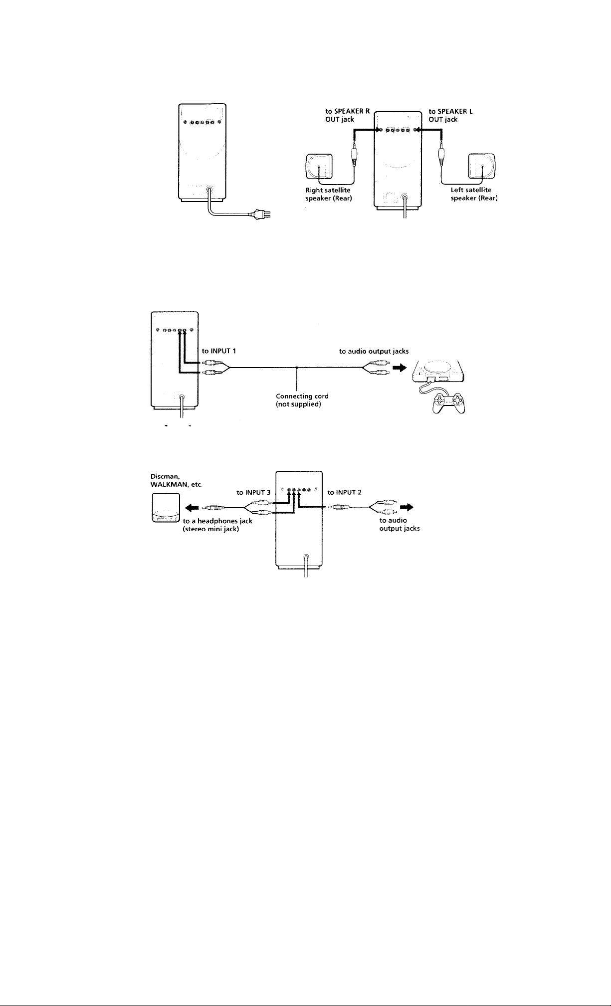
Connections
1 To power source
Woofer (Rear)
to a wall outlet
3 To home video game machine
Woofer (Rear)
2 To woofer
Woofer (Rear)
To AV equipment
Woofer (Rear)
Home video
game machine
CD player. VCR. TV,
etc.
Page 4

1 Connect the AC power cord to the wall
outlet.
2 Connect the left and right satellite speakers
to the woofer.
3 Connect the woofer to the source
equipment.
When the system is connected to a monaural jack of
a radio, etc., the sound may not come through the
right satellite speaker. When you use the optional
Sony plug adaptor PC-2.36HG, sound will come
through both satellite speakers.
Connecting to a stereo phone type
headphones jack
Use the optional PC-2.34HG plug adaptor or RKG138HG connecting cord.
Page 5

How to Use
1 Press the POWER switch (j=i. ON).
The POWER indicator lights up.
2 Set the INPUT SELECT switch.
Set the INPUT SELECT switch to I {for INPUT
1), 2 (for INPUT 2), or 3 (for INPUT ,3),
INPUT 1 is the "game position". The bass and
treble are emphasized when a home video
game machine, etc. is connected to INPUT 1
and played.
3 Adjust the volume with the VOLUME
control.
4 Adjust the bass level with the BASS LEVEL
control.
After listening, press the PCIWER switch (Jl OFF).
The POWER indicator goes off.
Listening to the sound through headphones
Connect the headphones to the 0 (headphones)
jack. The sound from the speakers is automatically
turnecf off. The bass cannot be emphasized with
the BASS LEVEL ct>ntrol.
Page 6

Attaching Satellite Speakers
1 Attach the speaker supports on the TV.
Clean dust and dirt from the TV. Remove the
adhesives from each speaker support, and
attach one speaker support to each side of the
TV by firmly pressing down.
2 Slide the satellite speakers into the speaker
supports.
Note
• If the sides of your 1V are curx'od and vou caniuit
attach the satellite speakers, place them on each
side of the IV. The qualit\ of the sound will be
unaffected.
Page 7

Precautions
On operating voltage
Operate the unit only on 120V AC, 60Hz.
On safety
•The nameplate indicating operating voltage,
power consumption, etc. is located on the rear
exterior of the woofer.
• Unplug the unit from the wall outlet when it is
not to be used ft>r an extended period of time. To
disconnect the cord, pull it out by grasping the
plug. Ne\’er pull it out by the cord.
• Should anv solid object or liquid fall into the unit,
disconnect the AC power cord, and ha\ e the unit
checked bv qualified personnel before operating it
anv further.
On installation
• Do not lea\ e the unit in a location near heat
sources, moi.-^turo, rain, or mechanical shock.
• Although this speaker system is magnetically
shielded, do n<H leave recorded tapes, watches,
personal credit cards, or floppy disks using
magnetic coding in front of the unit for an
extended period for precaution.
On cleaning the cabinet
Clean the cabinet with a soft cloth slightlv
moistened v\'ith water ('r mild detergent solution.
D(.i not use alcohol, benzine, or thinner as t!u‘\’ mav
mar the finish.
If the TV picture or monitor display is magnetically distorted
Although this s\ stem is magnetically shielded,
there may be cases that the picture on some TV
sets/personal computer sets mav become
magnetically distorted. In such a case, turn off the
power i)f the TV set/personal computer set once,
and after 15 to .50 nunutes turn it on again. For the
personal computer set, take the appropriate
measures such as data storage before turning it off.
When there seems to be no improvement locate
the system further awav from the TV set/personal
computer set. Furthermore, be sure not to place
objects in which niagnets are attached or used near
the '] V set/personal computer set, such as audio
racks, TV stands, hn’s, etc. These mav cause
magnetic distortitui to the pic^uгe due to their
interactiiMi with tlie ^^’stern.
if \ oLi ha\‘e an\ questit^ns or pr<_)hlems concerning
voLir s\'stem that are not co\ ered in this manual,
please ctmsult \'our nearest Scniv’ dealer.
Troubleshooting Guide
Should any problem persist ufter you have made
the folknvini; checks, consult your nearest Sonv
serx ice facilitx.
Trouble
\o sound at. all
No bass sound
No stuind from one channel
Distiii'tion
Cause and/or remedy
Connect the ,-\C power cord ty> a wall outlet
Set the I’OWHK switch to ON.
Check the IM'CT Sid kCT switch setting,
I urn the VOI L'MFi control cl('ckv\ ise.
Increasi' the sound \ cdume with the u>lume a>ntrc’l on the connected equipment.
Check the connecti'd ei.[uipmeni,
• Is the ek|iiipment turned oiC
♦ 1s operation of the connected equipment correct?
Check to see if the headphones is Ck>nnccted to the . . (headplumesl jack,
rurn the BASS id'VF.I. control dockwise.
Check to see if the' uxHifer/amplifier is connected to the motiaural earphoiH' jack. If it is
connected, List.' th«.- I’C'daO K- plug ariaplor to ad.ipf "tereo mini plug tt’ the nu''naural
mini pliig.
Clieck the satellite speakers connecting.
Turn dow'n the volume of the connected equipnu'nl.
Turn dow'n tile BASS LFV'l'l. control.
Page 8

Specifications
Woofer section
Amplifier section
Rated output WtH>tcr section; 13 W
Input impedance 4.7 kilohms (1 kHz)
Input 3 inputs 3 jacks
Output Stereo) mini jack (fc>r headphones)
Speaker section
Svsteni L«n\ range, bass-relle.\ f\ pe
Speaker unii Magneticalh shielded, mm (3 , in.)
Nominal impi-dance
Speaker st'nsitivilv
General
Power rei]uiremeiits
Power consuniption
Dimension^. Approv. 132 mm \ 271 mm \ 222 mm
Mass Approx. 2.7 kg (5 lb. 15 o/.)
Cord length 2 m (7<S/-in.)
Mid and high range section: 5 W + 5 W
Total; 25 W (at 10'^.. harmonic distortion)
Rhone jacks (I\'PUT 1) {game
position)
Stereo mini jack (INPUT 2)
Phono jacks (INPUT 3)
Stereo mini jacks (L/R) (tor satellite
speakers)
dia.
4 <ihm^
's3dB/\V/m
120 V AC . (41 ! 1/
25 W
iu/h.'d) {5h'A \ 10 i \ \ SV; in.) not
mduding pix^iecting parts and c<inti\4s
Speaker sensitix itv
Rated input power
Maximum input power
Dimensions
Mass
Cord length
'86dB/W/m
5 W
low
Approx. 100 mm x 94 mm x 83 mm
(w/h/d) (4 X 3V^ X 3'7^ in.) not
including projecting parts
Approx. 380 g (13.5 oz.) (one channel)
2 m (78V'‘,in.)
Supplied accessories
Connecting cord (stereo mini plug ^—►
two phono plugs, 2 m) (1)
Speaker supports (2)
Optional accessories
Connecting cord RK-G136HG/C530l-iC /GI29HG
Kxtension coró RK-C! 1 iHG/Cd3SHG
Plug adaptor PC-234HG/23M IG
Your dealer mav not handle some of the abox e listed sold
separateK accesstiries. Please ask the dealer for detailed
information about the riptional accessories available in
vour country.
Design and specifications are subject t(^ change without
notice.
Satellite speaker section
System iMid/high-range, enclosed t\ pe
Speaker unit Magnetically shielded. 65 mm (2'/s in.)
Nominal impedance
dia.
4 ohfl’is
 Loading...