

Sony SRP-F300 Operating Instructions Manual
2-347-035-12 (1)
Digital Audio Processor
SRP-F300
Operating Instructions
LIMITER
COMP
OVER
OVER
-6
-10
-20
ON OFF
-40
IN-1
IN-1
IN-1
OVER
OVER
IN-2
IN-2
IN-2
-6
-6
-6
HF
HF
HF
-10
-10
-10
MF
MF
MF
-20
-20
-20
LF
LF
LF
-40
-40
-40
8LF
8LF
8LF
OUTPUTINPUT
C
B
A21
LIMITER
LIMITER
F
E
D
LIMITER
LIMITER
OVER
IN-1
IN-1
IN-1
LIMITER
OVER
IN-2
-6
HF
-10
MF
-20
LF
-40
8LF
PROGRAM
IN-2
IN-2
OVER
OUTPUT STATUS
-6
HF
HF
-6
REMOTE I/D
-10
MF
MF
-10
-20
LF
-20
LF
-40
8LF
-40
8LF
LOCK
Thank you for purchasing a Sony Digital Audio Processor.
Before operating, please read this manual carefully.
Be sure to keep it properly for future reference.
RECALL
/ENTER
DISPLAY
UP
REMOTE
(RS-232C)
DOWN
DIGITAL AUDIO PROCESSOR SRP-F300
TABLE OF CONTENTS
WARNING...............................
PRECAUTIONS ........................
1 OUTLINE..............................
2 PARTS NAMES AND
FUNCTIONS .........................
3 DISPLAYS AND
OPERATION.........................
4 BUILT-IN SIGNAL
PROCESSING.......................
5 SPECIFICATIONS .................
6 DIMENSIONS ......................
2
4
5
6
9
13
17
19
In most set-ups, connect the RS-232C terminal to an
external computer. For external control see the attached
floppy disk, “Control Software Manual” and
“Communication Protocol Guide”. These instructions detail
operation of the unit and its signal processing.
WARNING
Notice for the Customers in the United Kingdom
IMPORTANT
The wires in this mains lead are coloured in accordance with the following code:
Blue: Neutral
Brown: Live
As the colors of the wires in the mains lead of this
apparatus may not correspond with the coloured
markings identifying the terminals in your plug,
proceed as follows:
The wire which is coloured blue must be connected to
the terminal which is marked with the letter N or
coloured black.
The wire which is coloured brown must be connected
to the terminal which is marked with the letter L or
coloured red. Do not connect either wire to the earth
terminal in the plug which is marked by the letter E or
by the safety earth symbol Y or coloured green or
green-and-yellow.
WARNING
To prevent fire or shock hazard, do not expose the
unit to rain or moisture.
To avoid electrical shock, do not open the cabinet.
Refer servicing to qualified personnel only.
Setting the voltage selector (voltage selector
equipped models only)
Check that the voltage selector on the rear panel is set
to the local power line voltage. If not, set the selector
to the correct position using a screwdriver before
connecting the AC power cord to a wall outlet.
VOLT AGE
SELECTOR
120V 230V
INFORMATION (For the customers in the
United States)
This equipment has been tested and found to comply
with the limits for a Class A digital device, pursuant
to Part 15 of the FCC Rules. These limits are designed
to provide reasonable protection against harmful
interference in a residential installation. This equipment generates, uses, and can radiate radio frequency
energy and, if not installed and used in accordance
with the instructions, may cause harmful interference
to radio communications.
However, there is no guarantee that interference will
not occur in a particular installation. If this equipment
does cause harmful interference to radio or television
reception, which can be determined by turning the
equipment off and on, the user is encouraged to try to
correct the interference by one or more of the following measures:
– Reorient or relocate the receiving antenna.
– Increase the separation between the equipment and
receiver.
– Connect the equipment into an outlet on a circuit
different from that to which the receiver is conThis symbol is intended to alert the user
to the presence of uninsulated “dangerous voltage” within the product’s
enclosure that may be of sufficient
magnitude to constitute a risk of electric
shock to persons.
This symbol is intended to alert the user
to the presence of important operating
and maintenance (servicing) instructions in the literature accompanying the
appliance.
nected.
– Consult the dealer or an experienced radio / TV
technician for help.
2

For the customers in Europe
This product with the CE marking complies with both
the ECM Directive (89/336/EEC) and the Low
Voltage Directive (73/23/EEC) issued by the Commission of the European Community.
Compliance with these directives implies conformity
to the following European standards:
• EN60065 : Product Safety
• EN55103-1 : Electromagnetic interference
(Emission)
• EN55103-2 : Electromagnetic Susceptibility
(Immunity)
This product is intended for use in the following
Electromagnetic Environment(s):
E1 (residential), E2 (commercial and light industrial),
E3 (urban outdoors) and E4 (controlled EMC environment ex. TV studio).
Peak inrush current
(1) Power ON, current probe method: 2A (240V)
(2) Hot switching inrush current, measured in
accordance with European standard EN55103-1:
2A (230V)
Für Kunden in Europa
Dieses Produkt besitzt die CE-Kennzeichnung und
erfülit sowohl die EMV-Direktive (89/336/EEC) als
auch die Dilevtive Niederspannung (73/23/EEC) der
EG-Kommission.
Die Erfüllung dieser Direktiven bedeutet Konformität
für die folgenden Europäischen Normen:
• EN60065 : Produktsicherheit
• EN55103-1 : Elektromagnetische Interferenz
(Emission)
• EN55103-2 : Elektromagnetische
Empfindlichkeit (Immunität)
Dieses Produkt ist für den Einsatz unter folgenden
elektromagnetischen Bedingungen ausgelegt:
E1 (Wohnbereich), E2 (kommerzleller und in
beschränktem Maße industrieller Bereich), E3
(Stadtbereich im Freien) und E4 (kontrollierter EMVBereich, z.B. Fernsehstudio).
Spitzenstrom
(1) Einschaltstrom, Stromsonde: 2A (240V)
(2) Gemossen in EN55103-1: 2A (230V)
Pour les clients européens
Ce produit portant la marque CE est conforme à la fols
à la Directive sur la compatibilité électromagnétique
(EMC) (89/336/CEE) et à la Directive sur les basses
tensions (73/23/CEE) émises par la Commission de la
Communauté européenne.
La conformité à ces directives implique la conformité
aux normes européennes suivantes:
• EN60065 : Sécurité des produits
• EN55103-1 : Interférences électromagnétiques
(émission)
• EN55103-2 : Sensibilité électromagnétique
(immunité)
Ce produit est prévu pour être utilisé dans les environnements électromagnétiques suivants:
E1 (résidentiel), E2 (commercial et industrie légère),
E3 (urbain extérieur) et E4 (environnement EMC
contrôlé ex. studio de télévision).
Appel de courant de créte
(1) Mise sous tension (ON), méthode de sondago du
courant: 2A (240V)
(2) Mesuré conformément à ta norme européenne
EN55103-1: 2A (230V)
3

PRECAUTIONS
On safety
• Should any liquid or solid object fall into the cabinet, unplug the unit and have it checked by qualified personnel
before operating it any further.
• Unplug the unit from the wall outlet if it is not to be used for an extended period of time. To disconnect the cord,
pull it out by grasping the plug. Never pull the cord itself.
On installation
• Do not install the unit in a location near heat sources such as radiators or air ducts, or in a place subject to direct
sunlight, excessive dust, mechanical vibration or shock.
• When mounting the unit on the EIA 19-inch standard rack, allow enough space of 1U or more above this unit for
good ventilation.
On operation
• Before making program source connections, be sure to turn the power switch off and unplug the unit.
• When the unit is not used, turn the power off to conserve energy and to extend the useful life of your unit.
On cleaning the cabinet
Clean the cabinet, panel and controls with a soft cloth lightly moistened with mild detergent solution. Do not use
any type of abrasive pad, scouring powder or solvent such as alcohol or benzine.
On repacking
Do not throw away the carton and the packing material. It makes an ideal container for transporting the unit.
When shipping the unit for repair work or to another location, repack it as it was.
If you have any questions or problems concerning your unit, consult your nearest Sony dealer.
4

1.OUTLINE
Compact but flexible
This digital audio processor accommodates 2 channels for analog and digital input
and 6 channels for analog output in 1U size. It is available to use for various usage
such as a digital channel divider and an audio signal distributor.
Excellent sound quality
Its frequency characteristic extends to more than 40kHz and dynamic range (Aweight) is more than 110dB. The excellent sound quality is a result of sophisticated
design from circuit board to components.
Extremely precise data processing
The digital signal processor (DSP) is operates at 96kHz sampling frequency as well
as A/D and D/A. In addition, processed data is transferred at 48bit so that it can
achieve a massive internal digital headroom margin and obtain highly accurate
calculations.
Plenty of signal processing
The SRP-F300 is capable of providing a 31-band graphic equalizers, an 11-band
parametric equalizer, a compressor and a level control for 2-channels of input
signals. For each of the 6-channel outputs, it accommodates low-and high-cut
filtering up to 6th order for crossover, a 3-band parametric equalizer, a peak limiter,
a delay, a phase switcher and a level control. A test signal generater is provided
which has a pink noise and 20Hz -20kHz sine wave oscillator.
Effective adjustment
Signal processing is adjusted by an external computer via REMOTE terminal (RS-
232C) interface. (See “Control Software Manual”). A Windows
Interface (GUI) enables quick and simple adjustment.
95/98 Graphic User
Storage of up to 50 programs
Once you set up, it is possible to recall the stored programs in the unit without
connecting a computer.
5
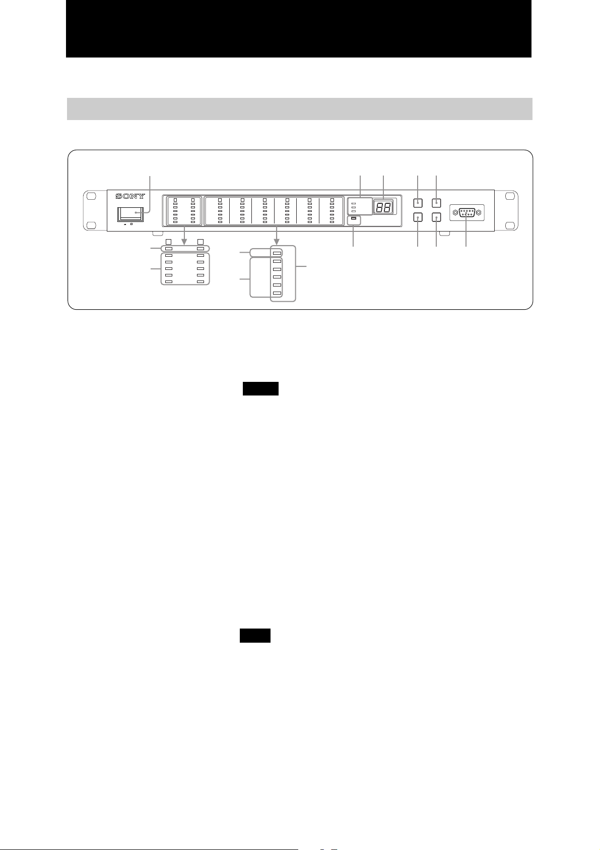
2. PARTS NAMES AND FUNCTIONS
2-1. Front panel
1 9 !7
OUTPUTINPUT
C
B
ON OFF
3
2
COMP
OVER
A21
LIMITER
COMP
OVER
-6
-10
-20
-40
-6
-10
-20
-40
IN-1
OVER
IN-2
-6
HF
-10
MF
-20
LF
-40
8LF
21
LIMITER
5
4
LIMITER
IN-1
IN-1
OVER
OVER
-10
-20
-40
IN-2
IN-2
-6
-6
HF
HF
-10
MF
MF
-20
LF
LF
-40
8LF
8LF
LIMITER
OVER
-6
-10
-20
-40
1 Power Switch
To turn the power on/off. When the unit is
turned on, the previous signal setting is recalled.
2 Input channel indicator (Refer to NOTE )
Indicates the peak input signal level. The selected
signal level is indicated. The indication is
updated every 100 msec and the indicated level
is the peak level in the previous 100 msec. When
generating a test signal, the level of the test signal
is indicated. (Use an external computer for
choosing input signal source).
RECALL
UP
D
LIMITER
IN-1
OVER
IN-2
-6
HF
-10
MF
-20
LF
-40
8LF
IN-1
IN-2
HF
MF
LF
8LF
LIMITER
LIMITER
OVER
-10
-20
-40
IN-1
IN-1
OVER
IN-2
-6
HF
MF
LF
8LF
PROGRAM
IN-2
OUTPUT STATUS
-6
HF
REMOTE I/D
-10
MF
-20
LF
-40
8LF
LOCK
8 " $#%
6
F
E
/ENTER
DISPLAY
REMOTE
(RS-232C)
DOWN
DIGITAL AUDIO PROCESSOR SRP-F300
5 Output channel peak limiter indicator
Illuminates when signal wave’s peak reaches the
limites setting level and clip has occurred at each
output channel. The indication changes at every
100 msec. If it lights up often, adjust the output
level as signal distortion is possible. (Use an
external computer to adjust).
6 Output channel assignment indicator
Indicates the current assignment of output
channel. The indications corresponds to the print
at the right side of the indicators. (Refer to page
9).
3 Compressor indicator
Illuminates when gain reduction takes place in
the compressor of the input channel. The indicator is updated every 100 msec. It does not light
up when compressor is not selected. (Use an
external computer to select and adjust the
compressor).
4 Output channel indicator (Refer to NOTE )
Indicates signal levels after processing all signals
of each output. The indications correspond to the
level scale printed at the left side of the indicators. The indication is updated every 100 msec
and the indicated level is the peak level in the
previous 100 msec. As it indicates the final
output signal level, it will not light up when the
output channel is muted.
7 DISPLAY mode indicator
Indicates the unit’s display mode. (Refer to page
9).
8 LOCK indicator
When lit, it is impossible to use the buttons on
the front panel.
This case means the audio processor is controlled
by an external computer or it is locked by
external control.
9 Number Display
Displays the current program number or REMOTE ID number. (Refer to page 9).
6
 Loading...