

Page 1

MEMORY DATA TRANSFER UNIT
SRPC-5
SR-PC4
OPERATION MANUAL [English]
1st Edition (Revised 1)
Page 2
Before operating the unit, please read this manual
thoroughly and retain it for future reference.
For SRPC-5
Important Safety Instructions
• Read these instructions.
• Keep these instructions.
• Heed all warnings.
• Follow all instructions.
• Do not use this apparatus near water.
• Clean only with dry cloth.
• Do not block any ventilation openings.
Install in accordance with the manufacturer’s
instructions.
• Do not install near any heat sources such as radiators,
heat registers, stoves, or other apparatus (including
amplifiers) that produce heat.
• Do not defeat the safety purpose of the polarized or
grounding-type plug. A polarized plug has two blades
with one wider than the other. A grounding-type plug
has two blades and a third grounding prong. The wide
blade or the third prong are provided for your safety. If
the provided plug does not fit into your outlet, consult an
electrician for replacement of the obsolete outlet.
• Protect the power cord from being walked on or pinched
particularly at plugs, convenience receptacles, and the
point where they exit from the apparatus.
• Only use attachments/accessories specified by the
manufacturer.
• Use only with the cart, stand, tripod, bracket,
or table specified by the manufacturer, or sold
with the apparatus.
When a cart is used, use caution when moving
the cart/apparatus combination to avoid injury from tipover.
• Unplug this apparatus during lightning storms or when
unused for long periods of time.
• Refer all servicing to qualified service personnel.
Servicing is required when the apparatus has been
damaged in any way, such as power-supply cord or plug
is damaged, liquid has been spilled or objects have fallen
into the apparatus, the apparatus has been exposed to
rain or moisture, does not operate normally, or has been
dropped.
WARNING
To reduce the risk of fire or electric shock,
do not expose this apparatus to rain or
moisture.
To avoid electrical shock, do not open the
cabinet. Refer servicing to qualified
personnel only.
THIS APPARATUS MUST BE EARTHED.
This apparatus is provided with a main switch on the rear
panel.
Install this apparatus so that user can access the main
switch easily.
To completely turn off the power, turn off the main power
switch on the rear panel.
WARNING:
Using this unit at a voltage other than 120 V may require
the use of a different line cord or attachment plug, or both.
To reduce the risk of fire or electric shock, refer servicing
to qualified service personnel.
This symbol is intended to alert the user to
the presence of uninsulated “dangerous
voltage” within the product’s enclosure
that may be of sufficient magnitude to
constitute a risk of electric shock to
persons.
This symbol is intended to alert the user to
the presence of important operating and
maintenance (servicing) instructions in
the literature accompanying the
appliance.
Attention-when the product is installed in Rack:
1. Prevention against overloading of branch circuit
When this product is installed in a rack and is supplied
power from an outlet on the rack, please make sure that
the rack does not overload the supply circuit.
2. Providing protective earth
When this product is installed in a rack and is supplied
power from an outlet on the rack, please confirm that
the outlet is provided with a suitable protective earth
connection.
3. Internal air ambient temperature of the rack
When this product is installed in a rack, please make
sure that the internal air ambient temperature of the
rack is within the specified limit of this product.
2
Page 3

4. Prevention against achieving hazardous condition
due to uneven mechanical loading
When this product is installed in a rack, please make
sure that the rack does not achieve hazardous condition
due to uneven mechanical loading.
5. Install the equipment while taking the operating
temperature of the equipment into consideration
For the operating temperature of the equipment, refer to
the specifications of the Operation Manual.
6. When performing the installation, keep the
following space away from walls in order to obtain
proper exhaust and radiation of heat.
Right, Left : 4 cm (1.6 inches) or more
Rear : 10 cm (4 inches) or more
When installing the installation space must be secured in
consideration of the ventilation and service operation.
• Do not block the ventilation slots at the left side and right
side panels, and vents of the fans.
• Leave a space around the unit for ventilation.
• Leave more than 40 cm of space in the rear of the unit to
secure the operation area.
When the unit is installed on the desk or the like, leave at
least 4 cm of space in the left and right sides.
Leaving 40 cm or more of space above the unit is
recommended for service operation.
WARNING: THIS WARNING IS APPLICABLE
FOR USA ONLY.
If used in USA, use the UL LISTED power
cord specified below.
DO NOT USE ANY OTHER POWER
CORD.
Plug Cap Parallel blade with ground pin
(NEMA 5-15P Configuration)
Cord Type SJT, three 16 or 18 AWG
wires
Length Minimum 1.5 m (4 ft .11 in.),
Less than 2.5 m (8 ft .3 in.)
Rating Minimum 10A, 125V
Using this unit at a voltage other than 120V
may require the use of a different line cord
or attachment plug, or both. To reduce the
risk of fire or electric shock, refer servicing
to qualified service personnel.
WARNING: THIS WARNING IS APPLICABLE
FOR OTHER COUNTRIES.
1. Use the approved Power Cord (3-core mains lead) /
Appliance Connector / Plug with earthing-contacts that
conforms to the safety regulations of each country if
applicable.
2. Use the Power Cord (3-core mains lead) / Appliance
Connector / Plug conforming to the proper ratings
(Voltage, Ampere).
If you have questions on the use of the above Power Cord /
Appliance Connector / Plug, please consult a qualified
service personnel.
CAUTION
The apparatus shall not be exposed to dripping or
splashing. No objects filled with liquids, such as vases,
shall be placed on the apparatus.
Do not install the appliance in a confined space, such as
book case or built-in cabinet.
CAUTION
The unit is not disconnected from the AC power source
(mains) as long as it is connected to the wall outlet, even if
the unit itself has been turned off.
For kundene i Norge
Dette utstyret kan kobles til et IT-strømfordelingssystem.
Apparatet må tilkoples jordet stikkontakt
Suomessa asuville asiakkaille
Laite on liitettävä suojamaadoituskoskettimilla
varustettuun pistorasiaan
För kunderna i Sverige
Apparaten skall anslutas till jordat uttag
For the customers in the U.S.A.
This equipment has been tested and found to comply with
the limits for a Class A digital device, pursuant to Part 15
of the FCC Rules. These limits are designed to provide
reasonable protection against harmful interference when
the equipment is operated in a commercial environment.
This equipment generates, uses, and can radiate radio
frequency energy and, if not installed and used in
accordance with the instruction manual, may cause
harmful interference to radio communications. Operation
of this equipment in a residential area is likely to cause
harmful interference in which case the user will be
required to correct the interference at his own expense.
You are cautioned that any changes or modifications not
expressly approved in this manual could void your
authority to operate this equipment.
All interface cables used to connect peripherals must be
shielded in order to comply with the limits for a digital
device pursuant to Subpart B of Part 15 of FCC Rules.
This device complies with Part 15 of the FCC Rules.
Operation is subject to the following two conditions: (1)
this device may not cause harmful interference, and (2) this
device must accept any interference received, including
interference that may cause undesired operation.
For the customers in Canada
This Class A digital apparatus complies with Canadian
ICES-003.
For the customers in Europe
This product with the CE marking complies with the EMC
Directive issued by the Commission of the European
Community.
3
Page 4

Compliance with this directive implies conformity to the
following European standards:
• EN55103-1: Electromagnetic Interference(Emission)
• EN55103-2: Electromagnetic Susceptibility(Immunity)
This product is intended for use in the following
Electromagnetic Environment: E4 (controlled EMC
environment, ex. TV studio).
For the customers in Europe
The manufacturer of this product is Sony Corporation, 17-1 Konan, Minato-ku, Tokyo, Japan.
The Authorized Representative for EMC and product
safety is Sony Deutschland GmbH, Hedelfinger Strasse
61, 70327 Stuttgart, Germany. For any service or
guarantee matters please refer to the addresses given in
separate service or guarantee documents.
This apparatus shall not be used in the residential area.
For the customers in Europe, Australia and New
Zealand
WARNING
This is a Class A product. In a domestic environment, this
product may cause radio interference in which case the
user may be required to take adequate measures.
For the customers in Taiwan only
For SR-PC4
WARNING
To reduce the risk of fire or electric shock,
do not expose this apparatus to rain or
moisture.
To avoid electrical shock, do not open the
cabinet. Refer servicing to qualified
personnel only.
WARNING
This unit has no power switch.
When installing the unit, incorporate a readily accessible
disconnect device in the fixed wiring, or connect the power
plug to an easily accessible socket-outlet near the unit. If
a fault should occur during operation of the unit, operate
the disconnect device to switch the power supply off, or
disconnect the power plug.
WARNING: THIS WARNING IS APPLICABLE
FOR USA ONLY.
If used in USA, use the UL LISTED power
cord specified below.
DO NOT USE ANY OTHER POWER
CORD.
Plug Cap Parallel blade
(NEMA 1-15P Configuration)
Cord Type NISPT-2 or SPT-2,
two 16 or 18 AWG wires
Length Minimum 1.5 m (4 ft .11 in.),
Less than 2.5 m (8 ft .3 in.)
Rating Minimum 7 A, 125 V
Using this unit at a voltage other than 120V
may require the use of a different line cord
or attachment plug, or both. To reduce the
risk of fire or electric shock, refer servicing
to qualified service personnel.
WARNING: THIS WARNING IS APPLICABLE
FOR OTHER COUNTRIES.
1. Use the approved Power Cord (2-core mains lead) /
Appliance Connector / Plug that conforms to the safety
regulations of each country if applicable.
2. Use the Power Cord (2-core mains lead) / Appliance
Connector / Plug conforming to the proper ratings
(Voltage, Ampere).
If you have questions on the use of the above Power Cord /
Appliance Connector / Plug, please consult a qualified
service personnel.
IMPORTANT
The nameplate is located on the bottom.
4
Page 5

For the customers in the U.S.A.
This equipment has been tested and found to comply with
the limits for a Class A digital device, pursuant to Part 15
of the FCC Rules. These limits are designed to provide
reasonable protection against harmful interference when
the equipment is operated in a commercial environment.
This equipment generates, uses, and can radiate radio
frequency energy and, if not installed and used in
accordance with the instruction manual, may cause
harmful interference to radio communications. Operation
of this equipment in a residential area is likely to cause
harmful interference in which case the user will be
required to correct the interference at his own expense.
You are cautioned that any changes or modifications not
expressly approved in this manual could void your
authority to operate this equipment.
All interface cables used to connect peripherals must be
shielded in order to comply with the limits for a digital
device pursuant to Subpart B of Part 15 of FCC Rules.
This device complies with Part 15 of the FCC Rules.
Operation is subject to the following two conditions: (1)
this device may not cause harmful interference, and (2) this
device must accept any interference received, including
interference that may cause undesired operation.
For the customers in Canada
This Class A digital apparatus complies with Canadian
ICES-003.
For the customers in Europe, Australia and New
Zealand
WARNING
This is a Class A product. In a domestic environment, this
product may cause radio interference in which case the
user may be required to take adequate measures.
For the customers in Europe
The manufacturer of this product is Sony Corporation, 17-1 Konan, Minato-ku, Tokyo, 108-0075 Japan.
The Authorized Representative for EMC and product
safety is Sony Deutschland GmbH, Hedelfinger Strasse
61, 70327 Stuttgart, Germany.
This apparatus shall not be used in the residential area.
For the customers in Taiwan only
5
Page 6

Table of Contents
Overview................................................................................ 8
Features ................................................................................... 8
System Configuration Example .............................................. 9
Names and Functions of Parts ..........................................10
Front ...................................................................................... 10
Rear ....................................................................................... 11
Setup.................................................................................... 12
Setup Flow ............................................................................ 12
Preparation ............................................................................ 12
Shared File Server Settings ................................................... 12
Displaying the Web Application Screen ............................... 12
Network Settings................................................................... 13
Mounting the File Server ...................................................... 14
Proxy Settings ....................................................................... 14
Saving and Recalling GUI Configuration Data .................... 16
Configuring the Monitor Output Signal................................ 16
Lookup Table (LUT) Settings............................................... 17
Configuring the Monitor Output Adjustment Settings.......... 17
Basic Operations................................................................ 19
Web Application Screen ....................................................... 19
Viewing Video Data Recorded on SRMemory Cards .......... 20
Importing Files ...................................................................... 20
VTR Video Data Operations............................................... 23
Connecting a VTR................................................................. 23
Setting a VTR........................................................................ 23
Displaying Video Data.......................................................... 25
Transferring Video Data ....................................................... 26
Transferring SRMemory Data to a VTR............................... 26
Other Operations ................................................................ 33
Editing and Viewing SRMemory Card Information............. 33
Viewing File Server Data...................................................... 33
Displaying the Web Client IP Addresses .............................. 34
Managing Log Files .............................................................. 34
Using Export Log Files ......................................................... 35
Automatic Execution Using a Job File.................................. 35
Checking File Systems (FSCK) ............................................ 36
Specifications ..................................................................... 36
SRPC-5.................................................................................. 36
SR-PC4.................................................................................. 37
6
Table of Contents
Page 7

Appendix ............................................................................. 38
Error/Warning Messages ....................................................... 38
Salvaging SRMemory Cards for which File Content
was Lost ....................................................................... 38
List of Keyboard Shortcuts.................................................... 39
Supported Formats ................................................................ 39
LUT File Formats Applicable to This Board ........................ 40
MPEG-4 Visual Patent Portfolio License ............................. 41
Job File Samples .................................................................... 41
Connecting the SRPC-5/SR-PC4 to the Shared File Server and
Transferring Files......................................................... 43
Notes on File Transfer........................................................... 46
Solving Problems related to eSATA HDD and SRPC-5/SR-PC4
Connections.................................................................. 46
Configuring FTP Server Settings .......................................... 46
Table of Contents
7
Page 8

Overview
The SRPC-5 or SR-PC4 (herein referred to as the “unit”)
is a data transfer unit used for displaying and transferring
materials recorded on an SRMemory card.
Using the unit, you can view materials recorded on an
SRMemory card on a master monitor, or transfer recorded
materials on an SRMemory card to a server or non-linear
editing equipment.
You can also transfer materials recorded on a VTR to a
server or write materials recorded on an SRMemory card
to a VTR by connecting the SRPC-5 and the VTR
(HDCAM-SR recorder on which an HKSR-5804 is
installed).
Operations can be performed via a web browser on a PC or
workstation. These operations include clip playback/
pausing, clip list display, and metadata confirmation/
editing.
Marks for model-specific functions
This manual uses the following markers to indicate
functions that are specific to the SRPC-5 or SR-PC4.
[PC5] : SRPC-5
[PC4] : SR-PC4
Write data recorded on SRMemory cards
to a VTR
[PC5] Materials recorded on SRMemory cards can be
written to VTR tape by connecting the SRW-5800, on
which an HKSR-5804 is installed, and the SRPC-5.
10 Gigabit Ethernet and eSATA support
By installing a commercially available 10GbE network
interface card into the PCIe expansion slot on the rear of
the unit, even faster data transfer is possible via 10 Gigabit
Ethernet.
By installing a commercially available eSATA card into
the PCIe expansion slot, you can transfer data to external
HDDs, etc.
For details on recommended third-party products, contact
your local Sony representative.
Features
View video recorded on SRMemory cards
The unit is equipped with an HD-SDI connector that
allows you to view video recorded on an SRMemory card
on a master monitor.
[PC5] The HD-SDI connector also supports 3G-SDI dual
link, allowing display of a wide range of formats.
Transfer data recorded on SRMemory
cards
Material recorded on an SRMemory card can be
transferred to a server or non-linear editing equipment via
Gigabit Ethernet.
Transfer data recorded on VTRs
[PC5] Materials recorded on a VTR can be transferred to a
server or non-linear editing equipment via Gigabit
Ethernet by connecting the SRW-5800, on which an
HKSR-5804 is installed, and the SRPC-5. VTR materials
can be transferred after converting them to DPX or MXF
format.
8
Overview
Page 9
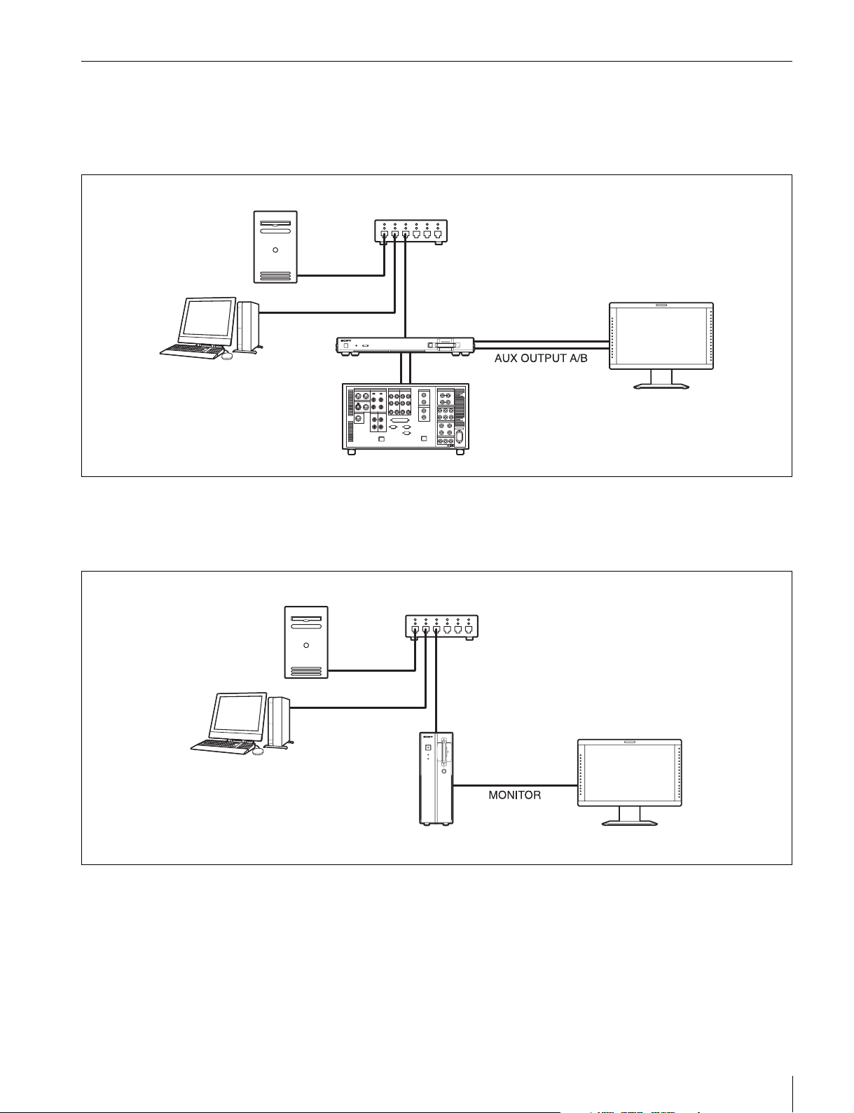
System Configuration Example
The following are examples of network system configurations in which data is transferred between a shared file server
using the unit.
For the SRPC-5
Shared file server
Web client
1) Connect the VTR if necessary. See “VTR Video Data Operations” on
page 23 for details on connecting the SRPC-5 to a VTR and then setting
up and operating the unit.
Switching hub
For the SR-PC4
Shared file server
SRPC-5
Switching hub
VTR
1)
HD monitor
Web client
SR-PC4
HD monitor
Overview
9
Page 10
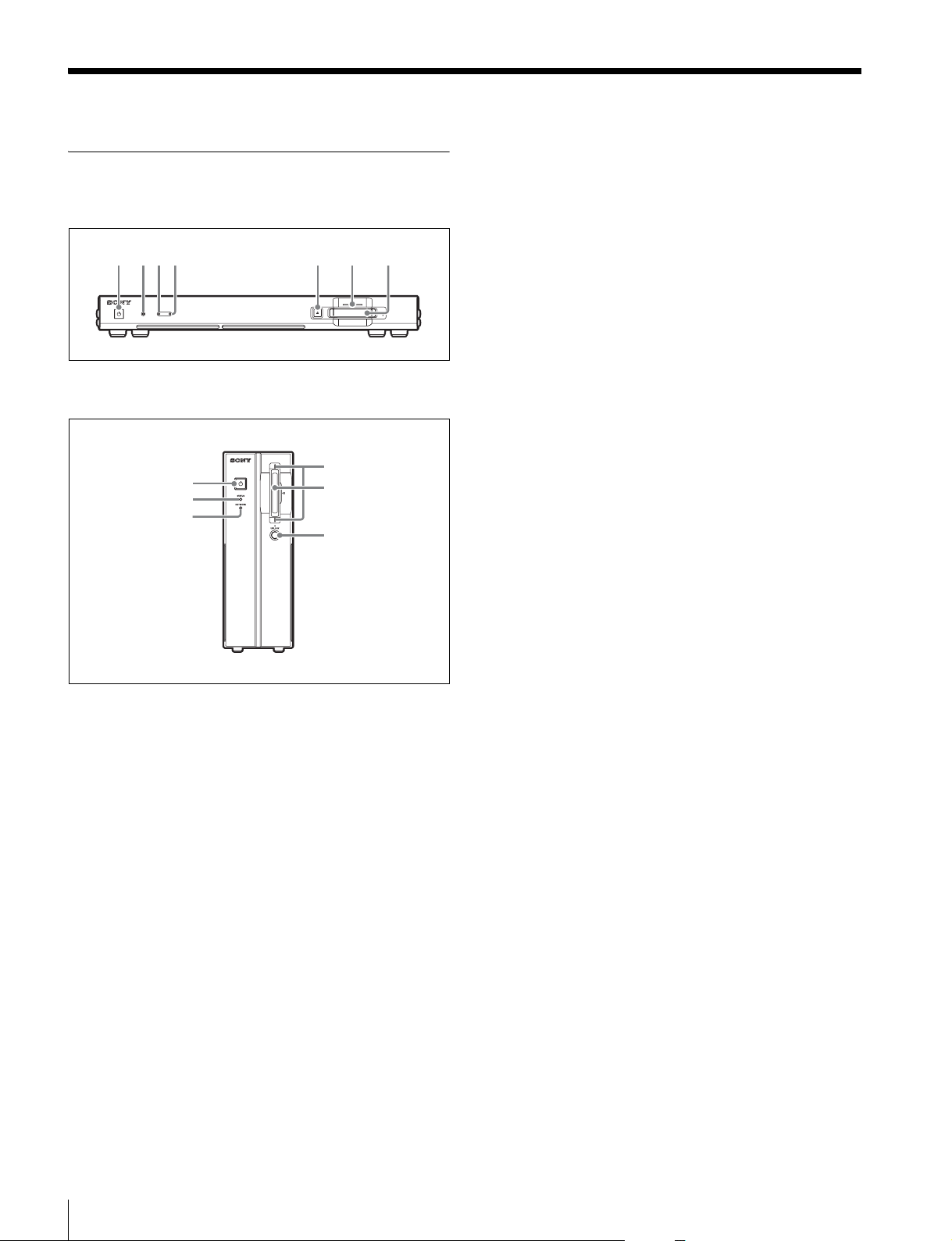
Names and Functions of Parts
Front
SRPC-5
1234 5 6 7
SR-PC4
1
2
4
6
7
8
Lit red: An error has occurred.
Blinking blue: The unit is starting up in default IP
address mode (see page 13).
c [PC5] VTR indicator
Displays the connection status between the SRPC-5 and
the VTR.
Off: The SRPC-5 is set to stand-alone mode or a VTR is
not connected.
Lit green: The SRPC-5 is properly connected to the VTR
and operating in VTR mode.
Lit yellow: A warning has occurred on the VTR.
Lit red: An error has occurred on the VTR.
Blinking red: The unit cannot connect to the VTR or
communication with the VTR is disabled. Restart the
unit and the VTR.
d NETWORK indicator
Displays the communication status between the unit and
the server.
Off: The server is not mounted.
Lit green: The server is mounted.
Blinking green: Data is being transferred.
e [PC5] Eject button
Press this to eject the SRMemory card.
a On/standby button
[PC5] When the main power switch on the rear of the unit
is turned on, this turns on the unit or sets it to standby
mode.
[PC4] Turns the unit on/off.
The button will light or blink based on the operating status
of the unit.
Lit red: The unit is in standby mode.
Blinking green: The unit is starting up.
Lit green: The unit is turned on.
Blinking green: If the button blinks green after startup,
the unit may be malfunctioning.
Blinking red: [PC4] If the button is blinking red before
the unit is turned on, the power supply voltage may be
incorrect.
If the button blinks green after startup or blinks red, stop
operation and contact your local Sony representative.
b STATUS indicator
Displays the status of the unit.
Lit green: Operating normally.
Blinking green: The unit is starting up.
Lit yellow: A warning has occurred.
f SRMemory indicator
Displays the status of the SRMemory card inserted in the
slot.
Off: The SRMemory card is logically detached from the
unit.
Lit blue: The SRMemory card is connected to the unit and
available for use.
Lit green: Data is being read from the SRMemory card.
Blinking blue
attached to or detached from the unit.
Blinking green
signals, such as file name changes, is being written.
Blinking purple
is being performed from the menu.
Blinking red
performed in response to an error.
Fast blinking red
1)
: The SRMemory card is logically being
1)
: Data other than audio and video
1)
: Files are being deleted or formatting
1)
: Salvaging or formatting is being
1)
: A problem was detected while
processing the SRMemory card. Eject or salvage the
card or perform the appropriate operation as instructed
by the message that appears.
1) Blinking LED: Blinks at 1-second interval.
Fast blinking LED: Blinks at 1/4-second interval.
g SRMemory slot
Insert the SRMemory card here.
10
Names and Functions of Parts
Page 11

Note
[PC4] Be sure to insert the SRMemory card all the way into
the slot. The card may not lock into place if it is not
inserted completely.
h [PC4] UNLOCK button
Unlocks the SRMemory slot.
Press this button to unlock the slot before removing an
SRMemory card.
Rear
SRPC-5
12345678
SR-PC4
c [PC5] VTR I/F OUTPUT connector
Connect this to the AUX INPUT connector on a VTR to
output signals to the VTR.
d [PC5] VTR I/F INTPUT connector
Connect this to the AUX OUTPUT connector on a VTR to
input signals from the VTR.
e [PC5] AUX INPUT connector
Used for future expansion. This is not used in this version.
f [PC5] AUX OUTPUT connector
HD SDI signals are output from here for connection to an
HD monitor.
g [PC5] AC IN connector
Connect the power cord here for connection to a power
outlet.
h [PC5] Main power switch
Use this to turn the power supply on/off. During regular
use of the unit, leave the main power switch in the on
position, and use the on/standby button on the front of the
unit to switch between operational mode and standby
mode.
2
1
9
0
a PCIe expansion slot
You can install a commercially available 10GbE card or
eSATA card here.
b NETWORK connector
Connect a network cable here to enable file transfer to the
file server and control of the unit from a web client.
CAUTION
• For safety, do not connect the connector for peripheral
device wiring that might have excessive voltage to this
port. Follow the instructions for this port.
• When you connect the NETWORK cable of the unit to
peripheral device, use a shielded-type cable to prevent
malfunction due to radiation noise.
Note
Always make sure that the unit is in standby mode before
setting the main power switch to the off position to turn off
the power.
i [PC4] MONITOR connector
HD SDI signals are output from here for connection to an
HD monitor.
j [PC4] DC IN connector
Connect the supplied AC adapter here and connect it to a
power outlet.
Notes
• Do not use AC adapters other than the one supplied.
• Before disconnecting the AC adapter, always turn off the
unit using the on/standby button on the front panel of the
unit.
Names and Functions of Parts
11
Page 12
Setup
Setup Flow
The following is an overview of the setup procedure.
Shared file server
The shared file server consists of a shared disk and stores
image data transferred from an SRMemory card and VTR.
The file server must support NFS server and CIFS server
functions. Any operating system is acceptable.
If an eSATA card is installed in the PCIe expansion slot,
an HDD connected via eSATA can be used as a shared
disk in place of a file server.
Connect the unit, shared file server, and web client
within a LAN (see page 12).
r
Configure the shared file server (see page 12).
r
Configure the network settings from the web client
(see page 13).
r
Mount the shared directory of the shared file server
from the web client (see page 14).
Memo
For details on using the SRPC-5 after connecting it to a
VTR, see “VTR Video Data Operations” on page 23.
Configuration examples for when the SRPC-5 or SR-PC4
is connected to a shared file server are described in
“Connecting the SRPC-5/SR-PC4 to the Shared File
Server and Transferring Files” of the Appendix on page
43.
Web client
The web client is a PC or workstation used to operate the
unit via the web application. It can also be used as a shared
file server.
A web browser is required (Internet Explorer, Safari,
Firefox, etc.). Any operating system is acceptable.
Note
Only one shared file server can be connected to the unit.
Up to five web clients can be connected to the unit at one
time.
Shared File Server Settings
Configure permission settings for the shared directory
mounted by the unit. Grant read, write, and execute
permissions to the unit (i.e., users).
You can configure the user ID and group ID in the
NETWORK tab of the DIAGNOSIS menu.
For details on file server settings, consult your system
administrator.
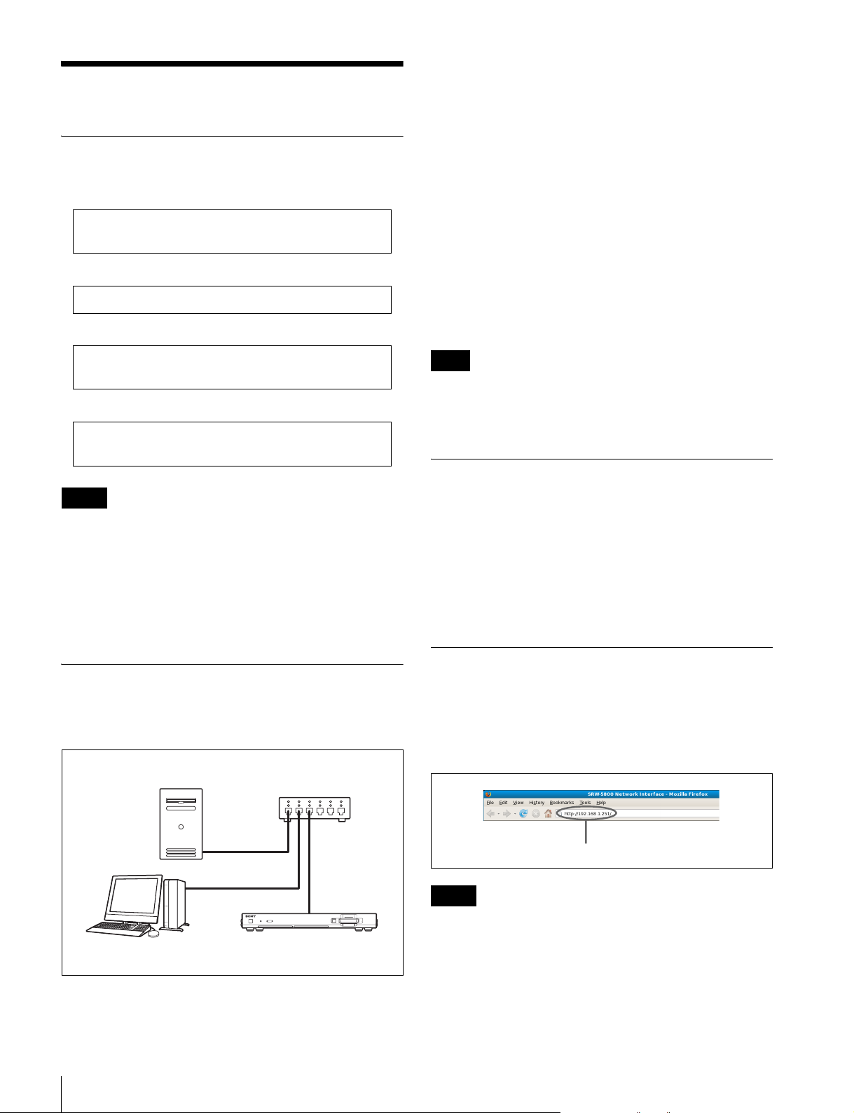
Preparation
Connect the unit, shared file server, and web client within
the same segment of the LAN (Gigabit Ethernet).
Shared file server
Web client
Switching hub
SRPC-5 or SR-PC4
Displaying the Web Application Screen
Enter the IP address of the unit in the address bar of the
web browser to display the web application screen of the
unit on the web client.
Enter the IP address of the unit here.
Notes
• The factory default setting for the IP address is
192.168.0.1. When displaying the web application
screen for the first time, enter “192.168.0.1” in the
address bar of the web browser.
• Before accessing the unit, make sure Javascript and
cookies are enabled in the web browser.
12
Setup
Page 13

• When the web application of the unit is used, the
[Return] and [Update] buttons in the browser menu do
not operate. If the display of the browser cannot be
updated or abnormality has occurred in the display
contents, do not click the [Update] button. In this case,
re-enter the IP address of the unit.
If you forget the IP address
If you forget the IP address of the unit, turn the unit off and
perform the following to restart the unit.
1
Hold down the eject button ([PC5]) or UNLOCK
button ([PC4]), and press the on/standby button.
2
Release the button when the STATUS indicator starts
to blink blue.
The unit starts up in default IP address mode, and the IP
address is reset to the factory default address, 192.168.0.1.
Enter this address in the web application to connect to the
unit, and verify or reconfigure the IP address as necessary.
Network Settings
Configure the unit’s IP address and other settings.
Note
When opening the web application and configuring
network settings for the first time, enter “192.168.0.1” in
the address bar of your web browser to display the web
application screen.
1
Click the DIAGNOSIS menu button in the web
application screen, and click the NETWORK tab.
The NETWORK tab screen appears.
After entering values for each item in the following
screen, press the Enter key and click the SET button to
confirm the values.
The settings will be applied after you finish
configuration and restart the unit.
2
Configure the following items under NETWORK.
IP ADDRESS: IP address of the unit.
SUBNET MASK: Subnet mask of the unit.
MTU: Maximum transfer volume for data in bytes.
Note
[PC5] When connecting the SRPC-5 to the VTR, set an
IP address that differs to the HKSR-5804’s address.
3
If necessary, configure the following items under
DOMAIN.
DOMAIN NAME: Network domain name.
DNS SERVER 1: IP address of DNS server 1.
DNS SERVER 2: IP address of DNS server 2.
DNS SERVER 3: IP address of DNS server 3.
DNS SERVER 4: IP address of DNS server 4.
4
Configure the following items under OTHERS.
DEFAULT GW: Default gateway of the unit.
HOST NAME: Host name of the unit.
UID: User ID of the unit.
GID: Group ID of the unit.
Note
Be sure to consult the file server administrator before
entering the appropriate values for UID and GID.
If you are transferring data through means other than the
NETWORK connector on the rear of the unit, configure
Setup
13
Page 14

the IP address of the network adaptor that will be used for
transfer as well.
When a commercially available 10GbE card or
other option is installed in the PCIe expansion
slot
Configure the IP address and other items under
NETWORK (OPTION 1) and NETWORK (OPTION 2).
Configure the settings so that the segments differ.
Mounting the File Server
Mount the shared disk of the file server as follows.
1
Click the DISK SETUP menu button in the web
application screen, and click the DISK CONTROL
tab.
For the DEV protocol
OPTION: Mount option.
DEVICE: Select the device that will be mounted from
the list of connected device types.
NODE: Select the node that will be mounted from the
list of connected device node names.
Note
The OPTION setting should be left blank during
normal use.
However, if you want to optimize transfer speeds by
specifying the block size for files at the time of disk
mounting, enter the data as shown in the following
example.
Example) wsize=32768, rsize=32768
Consult your file server administrator if the OPTION
setting requires configuration.
The DISK CONTROL tab screen appears.
2
Configure the TYPE setting to select the shared disk
protocol for the server to be mounted.
You can select from NFSv3, NFSv2, CIFS, or DEV.
When mounting a hard drive connected to an eSATA
card, select DEV.
Note
HFS+ is the recommended file system.
Be sure to unmount an HDD connected via eSATA
when removing it.
3
Configure the following settings based on the protocol
selected in step 2.
4
Click the MOUNT button to mount the file server or
device.
After the server is mounted, the MOUNT button will
change to the UNMOUNT button.
5
Configure the LIST TYPE setting to specify how
image clips on the shared directory of the mounted file
server are displayed.
Main: Display only the main image files.
Main+Proxy: Display main image files and proxies.
Others: Display non-image files.
To unmount the server
Click the UMOUNT button on the DISK CONTROL tab
screen.
14
For the NFSv3 or NFSv2 protocol
OPTION: Server mount option.
SERVER IP: IP address of the server.
SERVER DIR: Path to shared directory provided by
the server.
For the CIFS protocol
OPTION: Server mount option.
SERVER IP: IP address of the server.
SERVER DIR: Path to shared directory provided by
the server.
USER NAME: Name of user accessing the server.
DOMAIN: Domain to which the user belongs.
PASSWORD: Password used to access the server.
Setup
UMOUNT button
Note
Unmount the server before turning off the unit or before
the unit restarts after changing the unit format settings.
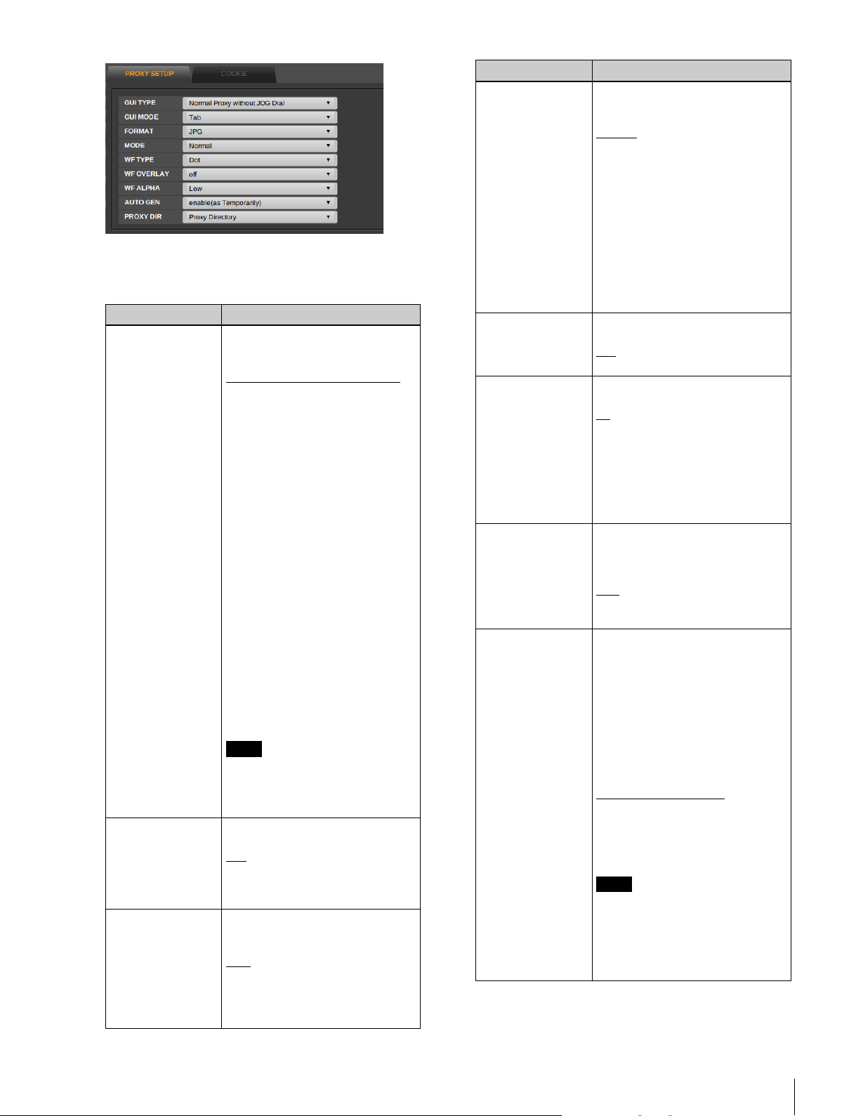
Proxy Settings
1
Click the PROXY SETUP menu button in the web
application screen, and click the PROXY SETUP tab.
The PROXY SETUP tab screen appears.
Page 15
2
Set the following items.
Underlined values in the table indicate default settings.
Item Function/settings
GUI TYPE Selects the size of the proxy and
GUI MODE Selects how the items in the
FORMAT Selects the file type of the proxy
whether the jog dial appears or
not in the GUI.
Normal Proxy without JOG Dial
The proxy is displayed with a
320-pixel width. The jog dial
does not appear in the MEM
CONTROL display or the
VTR/MEM CONTROL
display.
Normal Proxy with JOG Dial: The
proxy is displayed with a 320pixel width. The jog dial
appears in the MEM
CONTROL display or the
VTR/MEM CONTROL
display.
Large Proxy without JOG Dial:
The proxy is displayed with a
640-pixel width. The jog dial
does not appear in the MEM
CONTROL display or the
VTR/MEM CONTROL
display.
[PC5] This setting also determines
the file size of the proxy that is
generated automatically when
transferring data to a VTR.
Note
The proxy that appears in the
DISK SETUP menu is always
displayed with a 320-pixel width,
regardless of this setting.
display are shown.
: Items are divided into
Ta b
multiple tab displays.
Flat: Items are shown in one
display.
displayed on the GUI.
BMP: Bitmap
: JPEG
JPG
[PC5] This setting also determines
the type of the proxy file that is
generated automatically when
transferring data to a VTR.
Item Function/settings
MODE Selects the display mode of the
proxies that appear in the GUI
during tape playback.
: Displays the picture.
Normal
Waveform(Parade): Displays the
waveforms (red, green, and
blue).
Waveform(Red): Displays the
waveform (red).
Waveform(Green): Displays the
waveform (green).
Waveform(Blue): Displays the
waveform (blue).
Vector: Displays the vector scope.
Vector(×2): Displays the vector
scope at 2-fold magnification.
WF TYPE Selects the drawing method of the
:
WF OVERLAY Selects the display method of the
WF ALPHA Specifies the waveform
[PC5] AUTO GEN
(VTR mode only)
waveform.
: Dots
Dot
Line: Lines
waveform(s).
: Does not display the picture.
off
Only the waveform(s) is (are)
displayed.
on: Waveform(s) is (are) displayed
over the picture.
on(Mix):Waveform(s) and the
picture are mixed and
displayed.
transparency when the
waveform(s) and the picture are
mixed.
: Low transparency
Low
Middle: Medium transparency
High: High transparency
Determines whether or not
proxies are automatically
generated.
disable: Proxies are not generated
automatically.
enable: When previewing files in
the clip list and when
transferring files to VTR,
proxies are automatically
generated for picture files that
do not have their own proxies.
enable(as Temporarily)
are generated for display on
the GUI. However, the
generated proxies are not
stored on the disk.
Note
[PC5] Due to system limitations,
during the export of
uncompressed data, proxies are
not generated for main picture
files that are greater than about
62 MB.
: Proxies
Setup
15
Page 16
Item Function/settings
[PC5] PROXY DIR
(VTR mode only)
Determines the directory where
the generated proxies are stored.
Same as Main Files: Proxies are
stored in the same directory
as the main picture files.
Proxy Directory
is automatically created right
under the directory where the
main picture files are stored.
Proxies are stored in the
“proxy/” directory.
Resolution directory: When the
main picture files are stored
in directories labeled
according to size (e.g., 1920
× 1080), a directory for
storing small-size picture files
(e.g., 320 × 180) is created to
store proxies. When the main
picture files are not stored in
directories according to
picture file size, proxies are
stored in the same directory
where their main picture files
are stored.
When importing files, a
directory for storing main
picture files and a directory
for storing their proxies
labeled according to size
(e.g., 1920 × 1080, 320 ×
180) are created directly
under the specified directory.
The main picture files and
their proxies are stored in
these directories.
When importing
uncompressed files, note that
the “Resolution directory”
setting is not applied when
FILE DIR in the DISK
CONTROL tag display of the
IMPORT menu is set to “Org
Structure” and the original
picture files are not stored in
the directory according to
size. When FILE DIR is set to
“All Files into Selected
Directory,” directories
according to size are created.
: “proxy/” directory
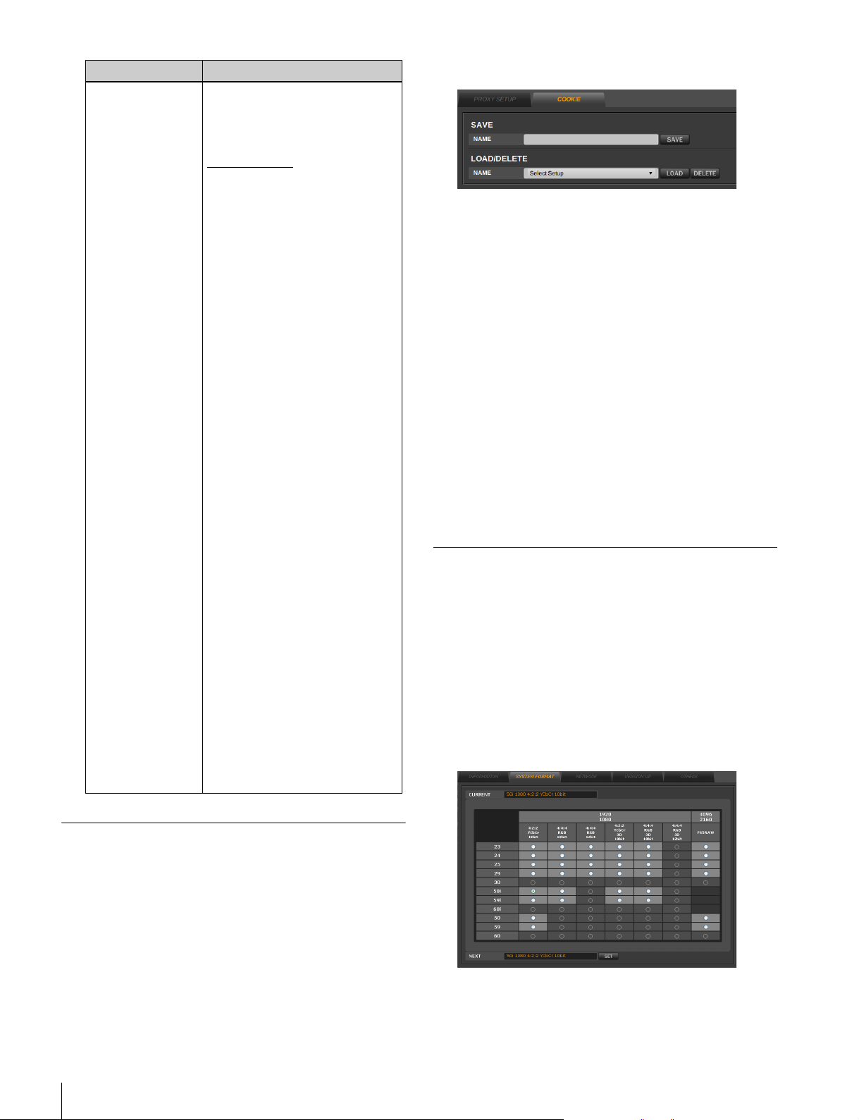
The COOKIE tab screen appears.
2
Enter a name for the cookie in the NAME box of the
SAVE area, and then click the SAVE button.
The entered file name is automatically appended with
the date.
Then, the cookie is stored in the directory for cookies
on the mounted server.
To recall GUI setup data
Click the NAME box of the LOAD/DELETE area, select
the stored cookie, and then click the LOAD button.
Selecting “Factory Preset” at this time resets the GUI
settings to their default values.
To delete GUI setup data
Click the NAME box of the LOAD/DELETE area, select
the stored cookie, and then click the DELETE button.
Configuring the Monitor Output Signal
You can select the type of SDI signal that is output from
the AUX OUTPUT connector ([PC5]) or MONITOR
connector ([PC4]) on the rear of the unit.
1
Click the DIAGNOSIS menu button in the web
application screen, and click the SYSTEM FORMAT
tab.
The SYSTEM FORMAT tab screen appears.
Saving and Recalling GUI Configuration Data
GUI configuration data is temporarily saved in your
browser’s cookies.
By naming this configuration data and saving it to the
mounted file server, you can recall the data later to restore
the previous configuration.
1
Click the PROXY SETUP menu button in the web
application screen, and click the COOKIE tab.
16
Setup
Page 17
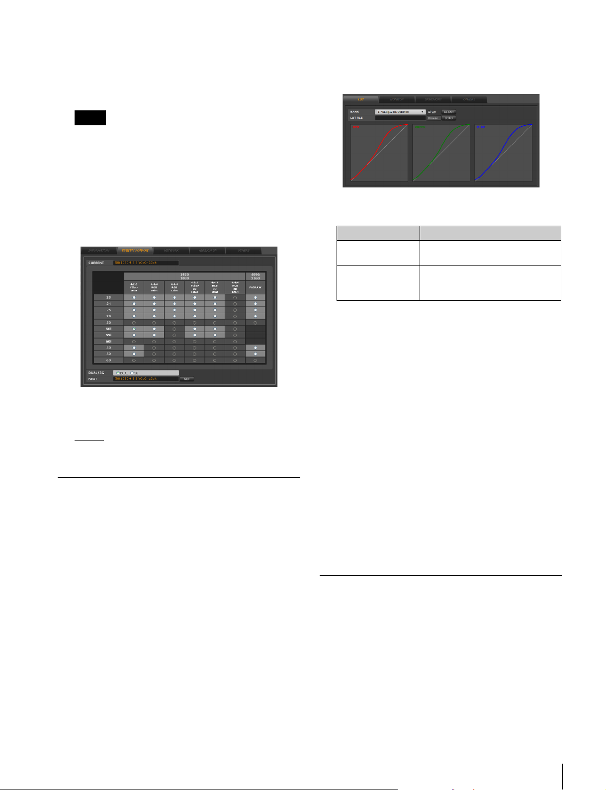
2
Select the video format in the matrix table.
Select the format from the “4096 × 2160 / F65RAW”
option in the matrix table when playing F65RAW
files.
Notes
• When playing F65RAW files, do not use it for any
purpose other than monitor output.
• When selecting any one of 23p, 24p, 25p or 29p
from “4096 × 2160 / F65RAW” in the matrix table,
those options will convert to 23PsF, 24PsF, 25PsF,
or 29PsF respectively and output to the monitor.
Additionally, when 50p or 59p is selected, those
options will convert to 25PsF or 29PsF and output to
the monitor.
1
Click the SRPC SETUP menu button, and click the
LUT tab.
The LUT tab screen appears.
2
Set the following items.
Item Function/settings
BANK Selects one of the eight banks
(BANK 1 to BANK 8).
WP check box Check this box when you do not
3
Click the [Browse…] button to open the local disk or
external media of the web client, then select the LUT
file. And then, click the LOAD button.
want to overwrite the contents of
the selected LUT bank.
3
[PC5] Select one of the following in the DUAL/3G
setting.
DUAL
: Dual link (1.5G HD SDI)
3G: 3G HD SDI output
Lookup Table (LUT) Settings
It is possible to load lookup table (LUT) files to the LUT
banks of the unit using the web application.
The eight LUT banks provided in the unit are used to store
LUTs that are used for importing, exporting data from the
tape and monitor signal output from the port.
LUT files stored in the banks are maintained even after the
unit and VTR are turned off.
The bit depth of LUT files can be applied 8, 10, 12, and 16bit data. Note, however, that the lower four of 16 bits are
ignored because of the hardware’s 12-bit process.
On the contrary, when the bit depth of the input data is 8 or
10, the signal is linearly interpolated into 12-bit data.
For details on applicable LUT file formats, see “LUT File
Formats Applicable to This Board” in “Appendix”.
The selected LUT file is loaded to the LUT bank
selected in step 2.
Clearing the contents of a LUT bank
Select the bank whose contents you want to delete, and
then click the CLEAR button.
Checking the names of files loaded to the
LUT bank from the VTR
Use the NETWORK2 SETUP menu from the OTHERS
CHECK menu within the MAINTENANCE menu of the
VTR.
For details on the MAINTENANCE menu of the VTR, refer
to the Installation Manual supplied with the SRW-5800.
Configuring the Monitor Output Adjustment Settings
Color control function for the monitor output can be set
using the web application or through control panel
operation on the VTR.
Setup
17
Page 18
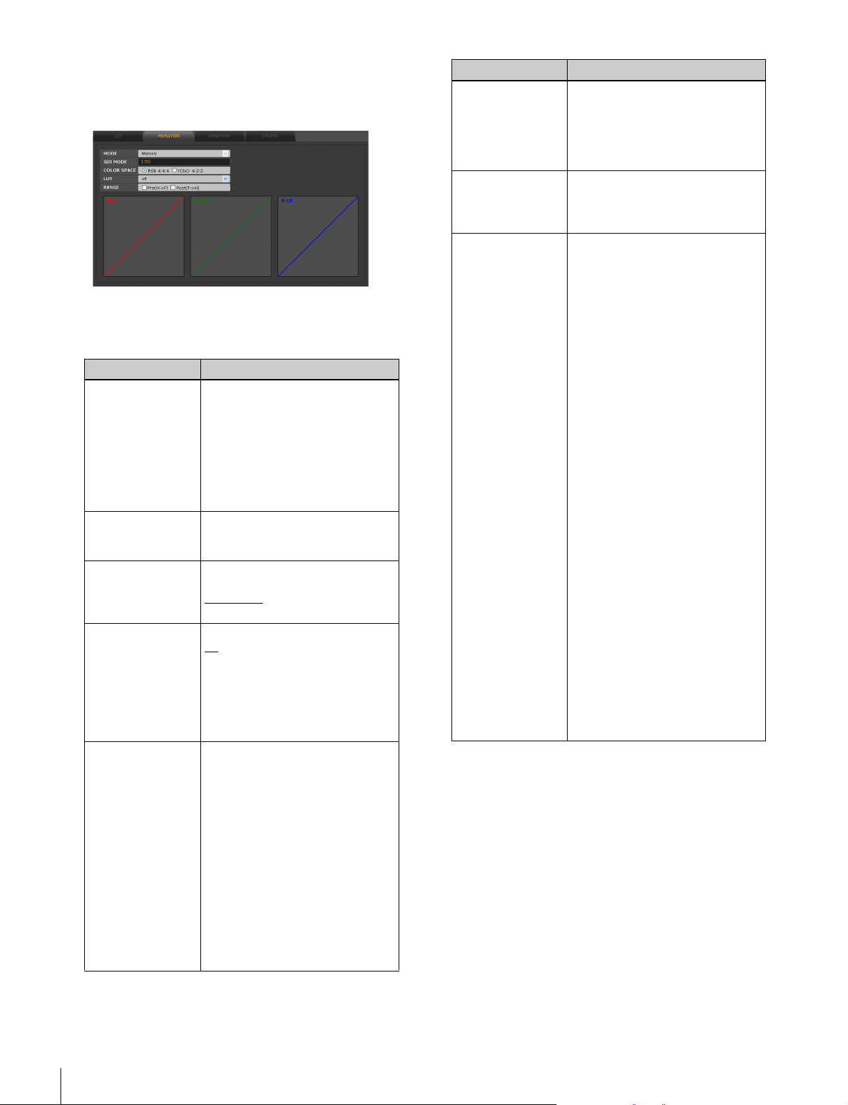
1
Click the SRPC SETUP menu button, and click the
MONITOR tab.
The MONITOR tab screen appears.
2
Set the following items.
Underlined values in the table indicate default settings.
Item Function/settings
[PC5] MODE
(when connected
to VTR)
[PC5] SDI MODE Selects the SDI signal type.
COLOR SPACE Specifies the monitor output
LUT Selects one of the eight banks.
RANGE Specifies whether the monitor
Selects the storage destination of
the video data to be output to the
monitor.
SRMemory: SRMemory card
video data is displayed in the
monitor.
VTR: VTR video is displayed in
the monitor when VTR is
connected.
1.5G: 1.5G HD SDI output
3G: 3G HD SDI output
signal type.
RGB 4:4:4
YCbCr: YcbCr 4:2:2 signal
: No LUT is used.
off
BANK1 to BANK8: The LUT in the
S-log1/2 to REC709 (800):
output signal is extended from
Head to Full before the LUT and
compressed from Full to Head
after the LUT.
Pre(HtF) checkbox: Check this
Post(FtH) checkbox: Check this
: RGB 4:4:4 signal
specified bank is applied to
the monitor output.
Converts files filmed by F65 in
S-log to REC709.
box to extend the effective
signal range of a monitor
output signal with headroom
to full range before the LUT.
box to compress a full range
monitor output signal to the
effective signal range of a
monitor output signal with
headroom after the LUT.
Item Function/settings
CROP POS (4K)
(only enabled when
the system format
is F65RAW)
EI
(only enabled when
the system format
is F65RAW)
3D MODE Left: [PC5] Outputs the Link A
Sets the position to crop the 1920
sample from the resized 2048
wide sample.
–128~+128 sample (in samples of
2): The set value will be held
until the unit is turned off.
Sets the sensitivity (EI value).
Auto: The EI value is set
automatically.
XXX: The EI value is set manually.
signal from the AUX OUTPUT
A connector, and the Link B
signal from AUX OUTPUT B
connector.
[PC4] Outputs the Link A
signal from the MONITOR
OUT connector.
Right: [PC5] Outputs the Link B
signal from the AUX OUTPUT
A connector, and the Link A
signal from AUX OUTPUT B
connector.
[PC4] Outputs the Link B
signal from the MONITOR
OUT connector.
H Split(L/R): Splits the display
horizontally with the Link A
signal output on the left side,
and the Link B signal output
on the right.
H Split(R/L): Splits the display
horizontally with the Link B
signal output on the left side,
and the Link A signal output
on the right.
V Split(L/R): Splits the display
vertically with the Link A
signal output on the top, and
the Link B signal output on
the bottom.
V Split(R/L): Splits the display
vertically with the Link B
signal output on the top, and
the Link A signal output on
the bottom.
18
Setup
Page 19
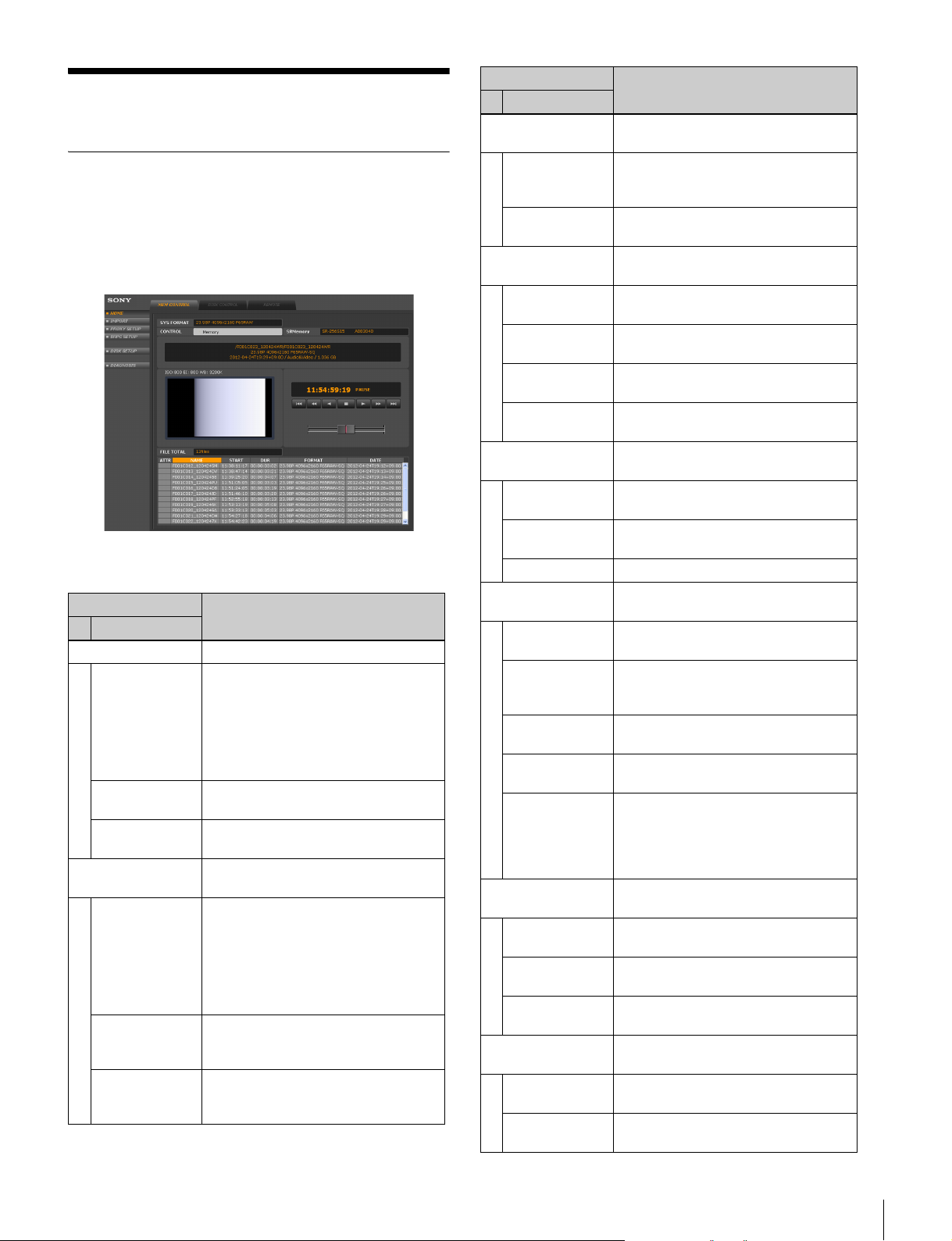
Basic Operations
Web Application Screen
Configuration and data transfer controls for the unit are
performed in the web application screen from a web client.
Contents of the web application screen
The web application screen consists of the following
contents.
Menu button Description
Tab
HOME Initial screen of the web application.
MEM
CONTROL
[PC5] VTR/MEM
CONTROL
(when
connected to
VTR)
DISK
CONTROL
REMOTE Displays the IP address of the client
IMPORT Allows you to import files from the
MEM
CONTROL
[PC5] VTR/MEM
CONTROL
(when
connected to
VTR)
DISK
CONTROL
FILE SETUP Allows you to configure the format
Displays video from VTR or the
SRMemory card.
Allows you to verify files stored on the
file server.
PC connected to the unit.
SRMemory card to the file server.
Displays data stored on VTR and the
SRMemory card, and allows you to
select videos for import.
Allows you to configure the storage
location, file names, and other
settings for the imported files.
and conversion methods for the
imported files.
Menu button Description
Tab
PROXY SETUP Allows you to configure proxy and
GUI settings.
PROXY SETUP Allows you to configure settings for
COOKIE Allows you to save and recall GUI
SRPC SETUP Allows you to configure settings for
LUT Allows you to configure lookup table
MONITOR Allows you to configure color settings
SRMEMORY Displays information and file lists for
OTHERS Allows you to configure settings for
DISK SETUP Allows you to configure system
DISK
CONTROL
LOG
CONTROL
JOB CONTROL Allows you to perform job file controls.
DIAGNOSIS Allows you to configure other detailed
INFORMATION Displays version information and the
SYSTEM
FORMAT
NETWORK Allows you to configure network
VERSION UP Allows you to perform version
OTHERS Sets the time and date, initializes the
[PC5] EXPORT
(VTR mode only)
VTR MEM
CONTROL
DISK
CONTROL
VTR SETUP Allows you to configure conversion
[PC5] VTR SETUP
(VTR mode only)
DC SETUP Allows you to configure down
CASSETTE Displays Tele-File information stored
the proxy display method and GUI
display style.
configuration data.
the unit.
(LUT) settings.
for monitor output signals.
the SRMemory card.
operation mode.
settings.
Allows you to mount/unmount the
shared file server.
Allows you to manage log files.
settings.
serial No., etc.
Allows you to select the format of the
SDI signal that is output to the
monitor.
settings.
updates.
unit’s settings, and performs a file
system check of the factory default
settings and HDD connected by
eSATA.
Allows you to copy data from the file
server to the VTR.
Allows you to specify an IN point of
the tape for copy.
Allows you to select files for copy.
methods for the copy files.
Allows you to configure VTR settings.
converter settings.
on the cassette tape.
Basic Operations
19
Page 20
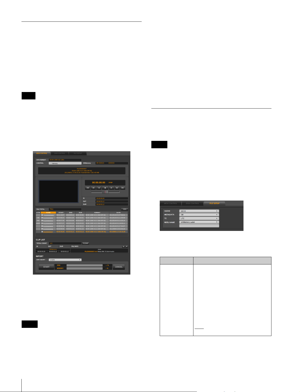
Viewing Video Data Recorded on SRMemory Cards
You can view video data stored on an SRMemory card via
a web browser or HD monitor connected to the unit by
accessing the MEM CONTROL tab screen from the
HOME or IMPORT menu.
Using the control buttons in the MEM CONTROL tab
screen, you can perform operations such as play, pause,
fast forward, and rewind for the video data.
Note
To play back files stored on an SRMemory card, you must
configure the frame frequency and color space in the
SYSTEM FORMAT tab of the DIAGNOSIS menu
beforehand.
For details, see “Configuring the Monitor Output Signal”
on page 16.
- Sound is muffled when files with a frame frequency
below 29p are played in a system above 50p. (and vice
versa)
- The sound will not play correctly when off-speed
playback is performed at below 29p or above 50p.
• The timecode is output in its original system format
when off-speed playback is performed.
You can display a jog dial and adjust the size of the proxy
screen for the GUI of the MEM CONTROL tab screen.
The GUI is configured with the GUI TYPE setting in the
PROXY SETUP tab screen of the PROXY SETUP menu
(see page 14).
Importing Files
You can import files stored on an SRMemory card inserted
in the unit to the shared file server.
Memo
Refer to “VTR Video Data Operations” on page 23 for
details about transferring video data recorded on a VTR to
a shared file server.
Files in the file list are color coded as follows to show files’
playback ability which depends on format status.
White: Playback or import is possible. (Yellow text
indicates formats that differ from the system.)
Dark grey: Import is possible.
Light grey: Playback and import are not possible.
Notes
• The following restrictions apply when playing files offspeed.
- Off-speed playback is not possible between interlaced
and progressive formats.
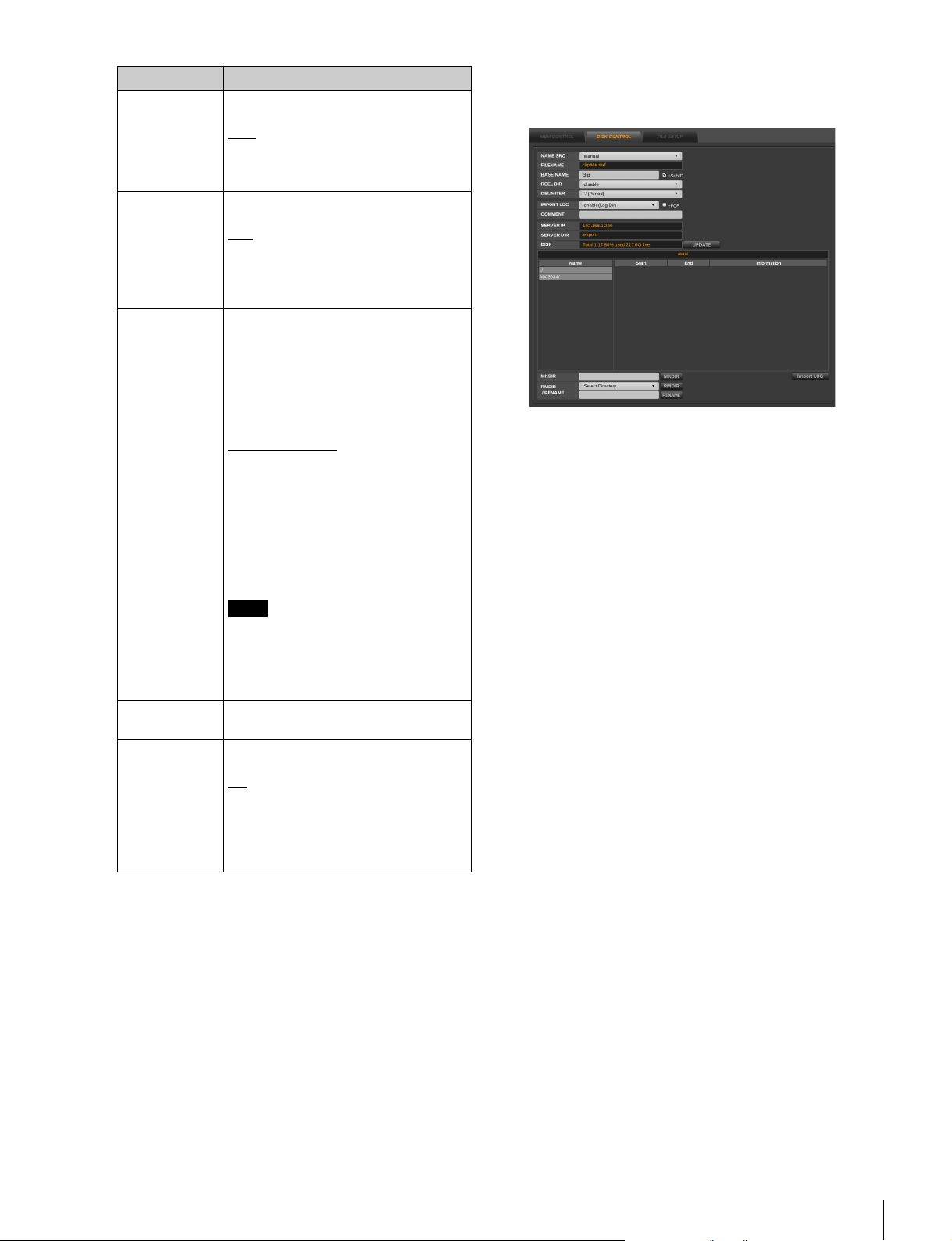
1
Click the IMPORT menu button in the web application
screen, and click the FILE SETUP tab.
The FILE SETUP tab screen appears.
2
Configure the following items.
Underlined values in the table indicate default settings.
Item Function/settings
AUDIO Specifies the number of audio
channels to be added to the imported
files.
0CH: No audio channel is added.
2CH: Channel 1 to 2
4CH: Channel 1 to 4
6CH: Channel 1 to 6
8CH: Channel 1 to 8
10CH: Channel 1 to 10
12CH: Channel 1 to 12
14CH: Channel 1 to 14
16CH: Channel 1 to 16
: Adds the channel numbers
Auto
stored in the imported files.
20
Basic Operations
Page 21
Item Function/settings
METADATA Selects whether to add ANC metadata
to the imported files.
: ANC metadata is not added.
OFF
ON: ANC metadata is added. Set to
ON when importing files in
F65RAW format.
TC Select the timecode to be included in
REEL NAME
(top field)
REEL NAME
(bottom field)
CHUNK When files for import are split, it sets
the header of the MXF file.
: LTC
LT C
VITC: VITC
Recount: Includes a timecode that is
generated using the timecode of
the first frame as a starting point.
Select one of the following as
information to be included in the
header of the imported file.
Manual: Includes the reel name
entered in the bottom field in the
header.
SRMemory ID: Includes the ID
assigned to the SRMemory card.
SRMemory Label
assigned to the SRMemory card.
Filename(Full): Creates directory from
the file name
Filename(8char): Creates directory
from the first eight letters of the
file name
Filename(4char): Creates directory
from the first four letters of the file
name
Note
The three Filename(Full),
Filename(8char) and Filename(4char)
items are displayed when Reel Name
is selected from REEL DIR in the
DISK CONTROL tab.
If [Manual] is selected in the top field,
enter a reel name.
the size of each file after splitting.
: Splitting disabled
Off
2GB: Splits in chunks of 2GB
4GB: Splits in chunks of 4GB
8GB: Splits in chunks of 8GB
16GB: Splits in chunks of 16GB
32GB: Splits in chunks of 32GB
: Includes the label
3
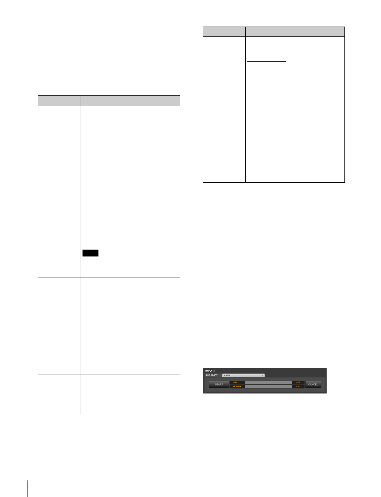
Click the DISK CONTROL tab.
The DISK CONTROL tab screen appears.
4
Select the directory in which to store the imported file
in the DISK CONTROL tab screen.
The file server directories and stored files appear at the
bottom of the screen. Open the directory in which to
store the imported files in this area.
To create, delete, or rename directories, use the
controls at the bottom of the screen.
To create a new directory
Enter a name for the new directory in the MKDIR
field, and click the MKDIR button.
The new directory is created directly under the
currently displayed directory.
When you enter the following character strings in the
directory name, the corresponding information is
retrieved from the system and automatically reflected
in the directory name.
The character stings that can be entered and the
information that is retrieved are as follows.
<memid>: SRMemory ID
<date>: Date (year, month, day)
<time>: Time (hour, minute, second)
The following is an example of the directory name
when the SRMemory card ID is “0123456789” and
“test<memid>_<date><time>” is entered at 17:42:35
on November 16, 2011.
test0123456789_20111116174235/
To rename a directory
Click the top box of the RMDIR / RENAME field, and
select the directory you want to rename. Enter a new
directory name in the bottom box of the RMDIR /
RENAME field, and click the RENAME button.
Basic Operations
21
Page 22
To delete a directory
Click the top box of the RMDIR / RENAME field,
select the directory you want to delete, and click the
RMDIR button.
5
Configure the following items in the DISK
CONTROL screen.
Underlined values in the table indicate default settings.
Item Function/settings
NAME SRC Specify the method in which imported
files are named.
Original
Manual: Renames the files during
BASE NAME When Manual is selected for NAME
SRC, this specifies the portion of the
name that will be common in all the file
names.
+SubID check box: Select this to add
Select the “+SubID” check box when
importing multiple files of the same
name to the same directory.
REEL DIR Selects whether to create a directory
named after the SRMemory card ID
when storing the file.
disable
SRMemory ID: Creates a directory
Reel Name: Creates a directory
Original Dir: Uses the original
DELIMITTER Specifies the delimiter to be used
between the file name specified in
BASE NAME and the serial number.
You can select underbars (_), periods
(.), or hyphens (-). The default setting
is a period.
: Uses the original file names
that are stored on the SRMemory
card.
import.
When “Manual” is selected, the
FILE NAME field appears under
NAME SRC. A sample file name
based on the settings you specify
will appear in this field.
sub IDs (for identifying clips) to
the file names. The sub ID is a
serial number that increases
sequentially by 1 with each file
imported.
Note
: A directory named after the
SRMemory card ID is not created.
The file will be saved directly
under the specified directory.
named after the SRMemory card
ID.
named after the reel name.
directory names that are stored
on the SRMemory card.
Item Function/settings
IMPORT LOG Specifies the import log file setting.
disable: An import log file is not
created.
enable(Log Dir)
be saved in the log directory.
enable(Selected Dir): An import log
file will be saved directly under the
directory you specify.
+FCP check box: Select this to
generate Final Cut Pro 7 format
XML files.
To view the created import log file,
click the Import LOG button at the
bottom right of the DISK CONTROL
tab.
For details on import log files, see
“Import log display” on page 23.
For details on managing import log
files, see “Managing Log Files” on
page 34.
COMMENT Enter comments to be included in the
import log file.
6
Click the MEM CONTROL tab.
: An import log file will
The MEM CONTROL tab screen appears.
7
Select the check boxes for the files to be imported, and
click the “Add” button.
The selected files are added to the CLIP LIST.
If you click the proxy screen, the file that appears in
the screen will be added directly to the CLIP LIST.
When you click the check box, the first image of that
file is displayed.
If you double-click a check box while pressing the
Shift key, all the check boxes will be selected. If you
double-click a check box while pressing the Ctrl key,
all the check boxes will be cleared.
You can only set the IN/OUT points and DURATION
for files playable in the format set in SYSTEM
FORMAT. Files are added to the CLIP LIST when
you double-click the GUI proxy after setup.
8
Click the START button in the IMPORT area.
File import starts.
During file import, the transfer status is indicated by a
progress bar and percentage in the DISK field.
22
Action when errors occur
You can specify the action to be taken if an error
occurs during import.
Underlined values in the table indicate default settings.
Basic Operations
Page 23
Item Function/settings
ERR ABORT Specify whether to abort import if an
error occurs.
: Import is aborted.
enable
disable: Import continues for as long
as possible.
Note
When [disable] is selected, import will
continue for as long as possible, but
proper operation is not guaranteed.
Select [enable] during normal use.
VTR Video Data Operations
You can transfer materials recorded on a VTR to a server
or write (copy) materials recorded on an SRMemory card
to a VTR by connecting the SRPC-5 and the VTR
(HDCAM-SR recorder on which an HKSR-5804 is
installed).
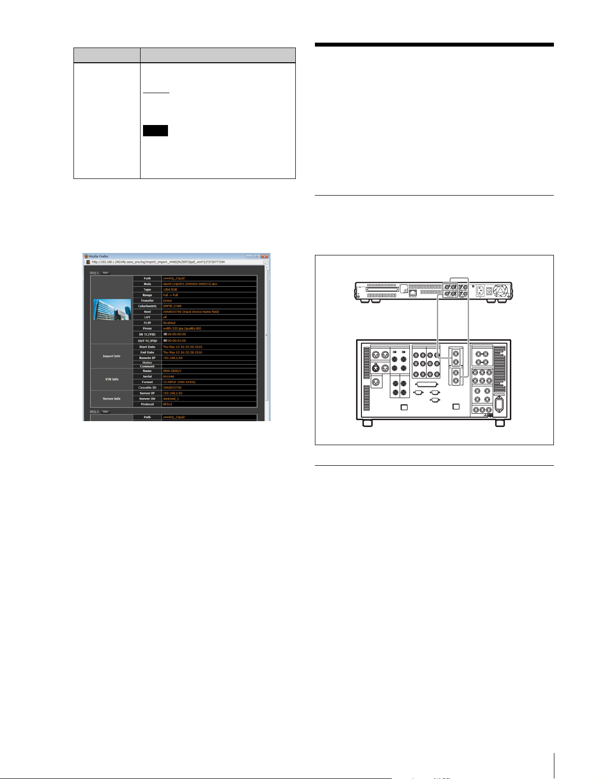
Import log display
Click the Import LOG button in the DISK CONTROL tab
screen to open the import log display. You can view the log
for each import (sequence).
To clear the contents of the import log display
Each sequence in the import log display can be cleared.
Click the DEL button at the beginning of the sequence
indication whose contents you want to clear.
Connecting a VTR
Connect the SRPC-5 to the VTR (SR-5800 with an
HKSR-5804 installed) as follows.
The unit
VTR I/F OUTPUT
AUX INPUT A/B AUX OUTPUT A/B
NETWORK
VTR
VTR I/F INPUT
AB
AB
INPUT
INPUT
AB
AB
OUTPUT
OUTPUT
VTR I F
AUX
Setting a VTR
The following settings are needed to transfer data between
the SRPC-5 and a VTR.
• Operation Mode Settings (see page 23)
• Format Settings (see page 24)
• VTR Remote Mode Settings (see page 24)
• SRPC Mode Settings (see page 24)
• Proxy and GUI Settings (see page 14)
• Monitor Output Signal Settings (see page 16)
• Downconverter Settings (see page 25)
• Lookup Table (LUT) Settings (see page 17)
Operation Mode Settings
Be sure to first set the operation mode in the web
application screen to enable data transfer between a VTR
and the SRPC-5.
VTR Video Data Operations
23
Page 24
1
Click the SRPC SETUP menu button in the web
application screen, and then click the OTHERS tab.
2
Set the items in the menu according to the format that
you want to use.
The OTHERS tab screen appears.
2
Select either “Auto” or “VTR” in the SRPC MODE
field.
Memo
• Auto: VTR connection is detected automatically,
and the unit operates in VTR mode when a VTR is
connected and in stand-alone mode when a VTR is
not connected. When a VTR is not connected,
system startup may take longer as the unit searches
for a connected VTR.
• The connection with a VTR is not enabled when
Stand Alone is selected in the SRPC MODE field.
Notes
• Restart the power for both the SRPC-5 and VTR
when changing the operation mode to connect to a
VTR.
• The unit cannot be operated from the HKSR-5804
when connected to a VTR.
Format Settings
This sets the format when transferring VTR data to a
server.
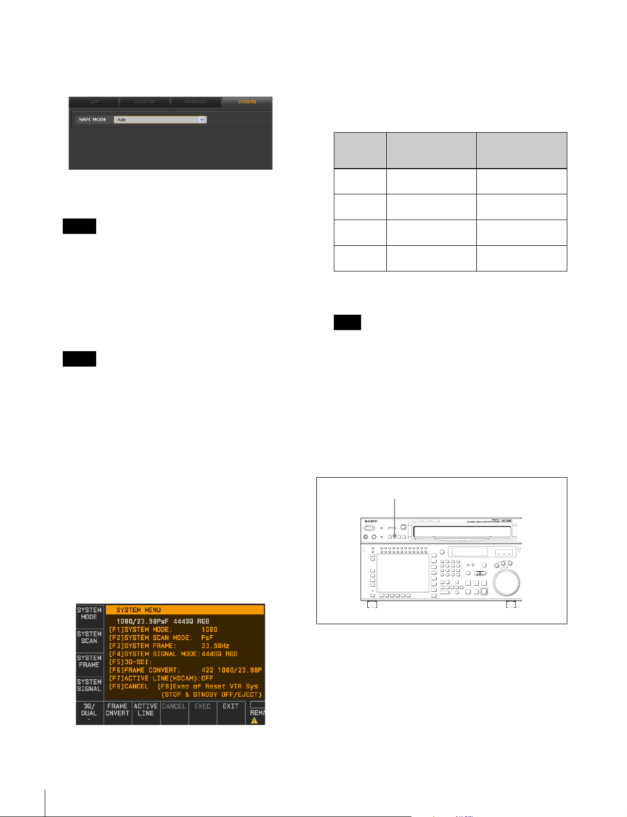
Perform this setting in the SYSTEM MENU in OTHERS
CHECK within the MAINTENANCE menu of the VTR.
To downconvert 4K/2K files for recording in HD
format, set the items to the values indicated in the
columns below the “Compression (HDCAM-SR)
format” header in the table below.
SYSTEM
MODE
SYSTEM
SCAN
SYSTEM
FRAME
SYSTEM
SIGNAL
Compression
(HDCAM-SR)
format
1920 × 1080
1280 × 720
PsF or
InterlaceProgressive
23.98, 24, 25, 29.97,
30, 50, 59
444SQ, 422 or
444HQ
Uncompression
(DATA) format
DATA
PsF
25 or 29.97
—
The formats described in the table above are the VTR
formats supported by the SRPC-5.
Note
The AUX output from the SRPC-5 is not guaranteed
when the SRW-5800 is set to a system format other
than the ones described in the table above.
VTR Remote Mode Settings
Be sure to set VTR to remote mode to enable data transfer
between the VTR (SRW-5800) and the SRPC-5 via a web
application.
Press the NETWORK 2 button on the upper control panel
of the SRW-5800 to light it.
NETWORK 2 button
For details on the MAINTENANCE menu of the VTR, refer
to the Installation Manual supplied with the SRW-5800.
1
From the VTR, open the SYSTEM MENU in the
OTHERS CHECK menu.
24
VTR Video Data Operations
SRPC Mode Settings
Be sure to set the VTR to SRPC mode when using the
SRPC-5 with a connected VTR. Select NW CTRL t NW
I/O MODE in the VTR’s SETUP menu and set SDI
MODE to SRPC.
For details on the MAINTENANCE menu of the VTR, refer
to the Installation Manual supplied with the SRW-5800.
Page 25
Automatic changes in the VTR SETUP menu
settings that occur during VTR operations
conducted through the web application
The settings of the following items in the VTR SETUP
menu of the SRW-5800 will be changed automatically, as
indicated below, when the respective VTR operations are
conducted through the web application.
• Import or export of files
- Menu item “606: TCG MODE select” changes to
“regene”.
- Menu item “607: TCG REGENE SOURCE select”
changes to “int-LTC”.
• First Rec (first recording operation)
Menu item “601: DF/NDF MODE select” changes to
“drop frame” or “non-drop frame” according to the
setting on the web application.
• Any VTR operation (including import and export)
- Menu item “005: SERVO AV REFERENCE select”
changes to “input”
- Menu item “602: TIMER MODE select” changes to
“TC”.
- Menu item “A10: 9-pin TC sense select” changes to
“LINE”.
1) It is recommended that you leave the “input” specification as is during
use of the networking function of the SRPC-5.
VTR SETUP menu settings to prevent import or
export failure
During import or export, the SRW-5800 repeats “run and
stop” movement. If the SRW-5800 enters standby off
mode while stopped (in STILL status) during import or
export, the SRW-5800 may fail to servo-lock by the time
it reaches the next IN point. This will cause the import or
export operation to be canceled. To prevent this, it is
recommended that menu item “501: STILL TIMER” in the
VTR SETUP menu of the SRW-5800 be set to eight
minutes (the default setting) or longer.
If the same problem occurs due to extremely slow network
speed, etc., the menu item “501: STILL TIMER” setting
should be even longer to prevent the SRW-5800 from
entering tape protection mode while in stop (STILL)
status.
1)
.
Displaying Video Data
You can view video data stored on a SRMemory card or
VTR via a web browser or HD monitor connected to the
unit by accessing the VTR MEM CONTROL tab screen
from the video data’s HOME, IMPORT, or EXPORT
menu.
Using the control buttons in the VTR MEM CONTROL
tab screen, you can perform video data operations such as
play, pause, fast forward, and rewind.
You can display a jog dial and adjust the size of the proxy
screen for the GUI of the VTR MEM CONTROL tab
screen. The GUI is configured with the GUI TYPE setting
in the PROXY SETUP tab screen of the PROXY SETUP
menu (see page 15).
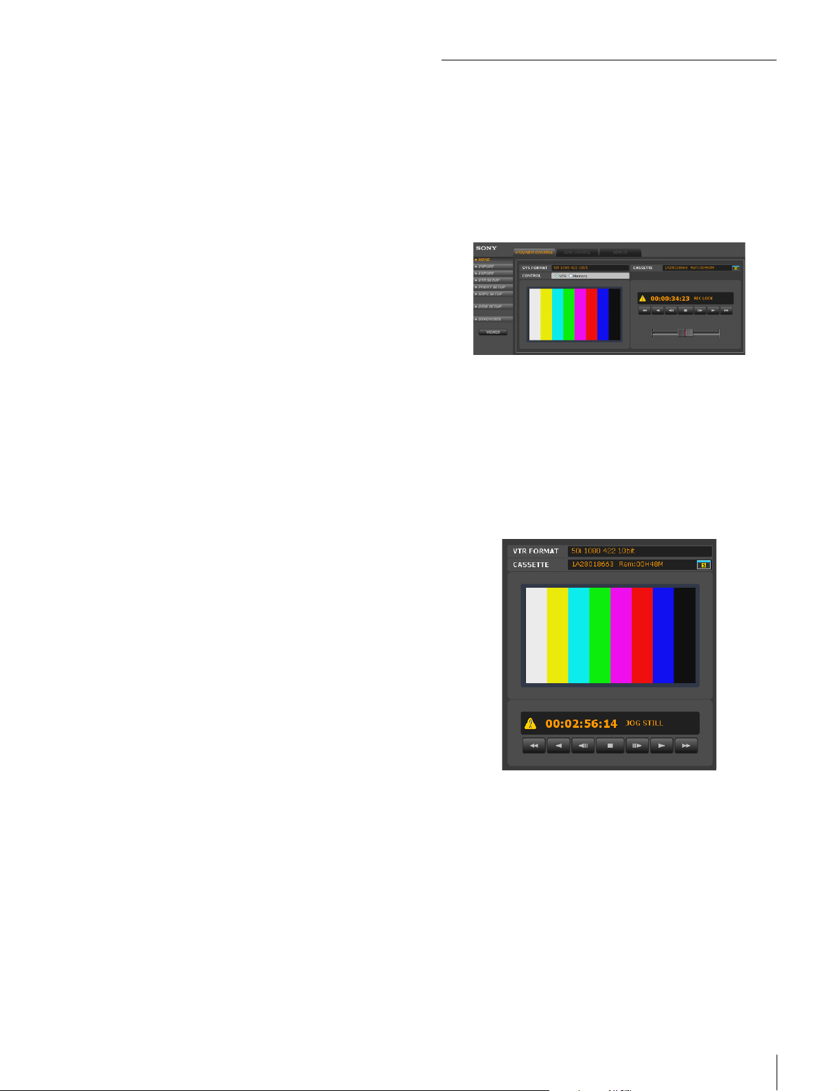
In VTR mode, the VIEWER button appears on the right
side of the web application screen. The VIEWER window
appears when this is clicked.
Downconverter Settings
Configure downconverter settings for outputting
downconverted VTR data to the monitor or for recording
downconverted data when copying to the VTR.
Downconverter settings are configured in the DC SETUP
tab screen of the DISK SETUP menu.
Refer to the operating instructions for the HKSR-5804 for
more details.
The video data controls available in the VTR MEM
CONTROL screen are also available in the VIEWER
window.
Differences in the VTR MEM CONTROL
window during processing of compressed
data and uncompressed data
When processing compressed data (HDCAM-SR format),
the current position on the tape is displayed by the
timecode. When processing uncompressed data (DATA
format), the current position on the tape is displayed in
picture IDs instead of the timecode. A picture ID consists
VTR Video Data Operations
25
Page 26
of six digits in the first part and two digits in the last part.
The first six digits constitute the serial number of the
image data, and the last two digits constitute the serial
number that indicates the specific frame (portion) of the
image data. (Portions are counted in single-frame units
based on the frames in HD images compressed in the
HDCAM-SR format.)
To display picture IDs on the control panel of the
VTR (uncompressed data only)
Set VTR SETUP menu item “635: PICTURE ID
DISPLAY” to “on”.
To display file information on the VTR control
panel (uncompressed data only)
Set VTR SETUP menu item “604: TC2 MODE SEL” to
“off” to display the file information under the timecode
indication on the control panel of the VTR.
• A black screen is recorded for six seconds prior to the
selected file.
• When each file has been copied, the OUT point image is
freezed and recorded for six seconds.
Memo
• 4:2:2 SR-Lite format files in the SRMemory are
converted to 4:2:2 SR-SQ and recorded.
• By setting the VTR system setting to double speed, you
can record 4:2:2 SR-Lite and SR-SQ/4:4:4 SR-SQ files
at double speed.
Note
Close the GUI of the PC during copy operations.
Opening the SRMemory
1
Press the CUE button and the ALT key.
The ALT+CUE menu appears.
2
Press the F2 (SRMem) key.
File information
For details on the VTR SETUP menu of the SRW-5800,
refer to the Operation Manual supplied with the
SRW-5800.
Transferring Video Data
You can transfer video data saved in the VTR to a shared
file server via the SRPC-5.
For details on importing from a VTR, refer to “Importing
Files” in the operating instructions for the HKSR-5804.
Transferring SRMemory Data to a VTR
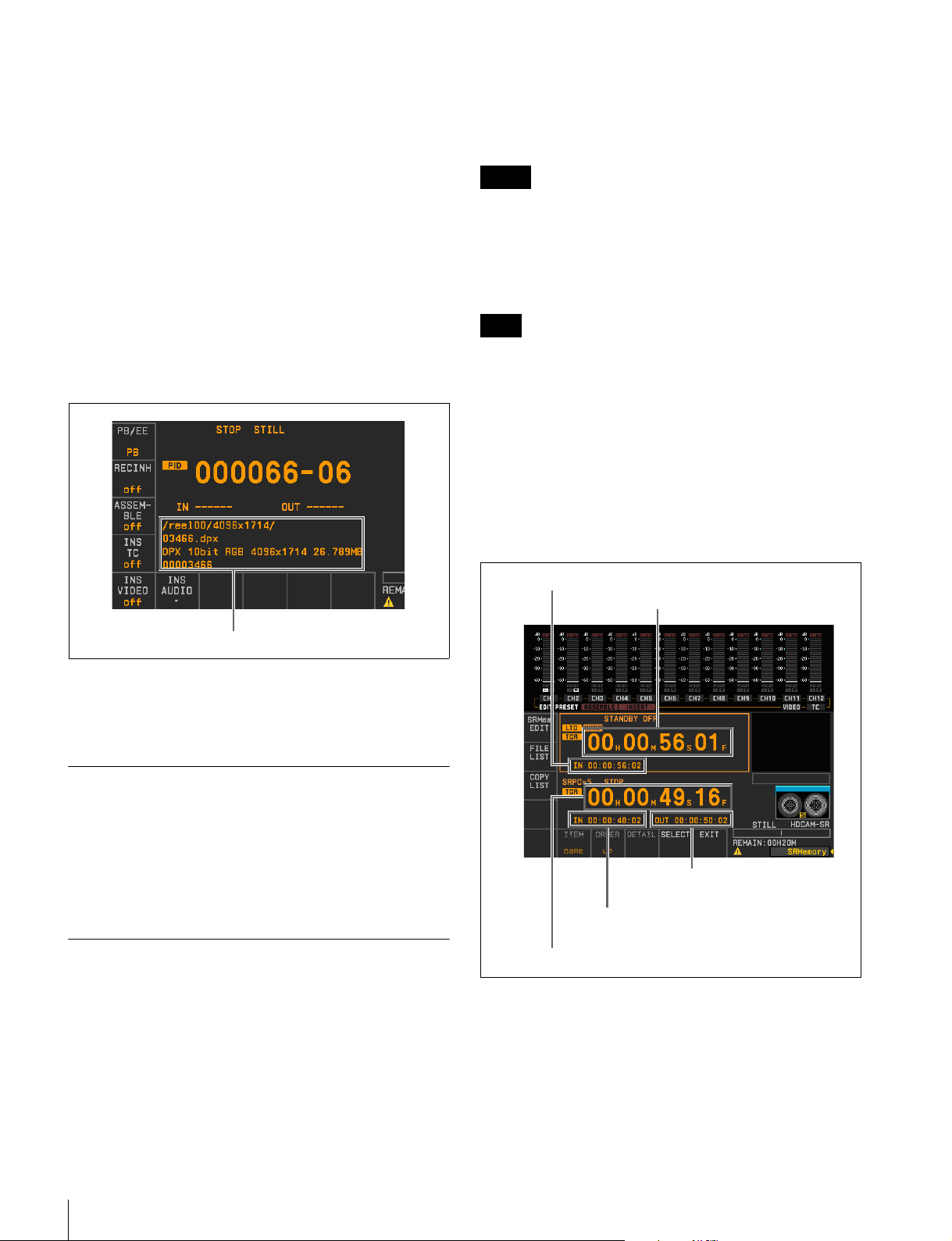
The SRMemory menu appears.
IN point of the copy VTR
VTR timecode
OUT point of the copy file
IN point of the copy file
Timecode of the SRPC-5’s current file
You can write (copy) video data recorded on SRMemory
to VTR tape. Write operations are performed via the
VTR’s control panel.
When copying is initiated, video data is recorded by the
following methods.
• The timecode is recorded according to the timecode
recorded in the SRMemory.
26
VTR Video Data Operations
Page 27
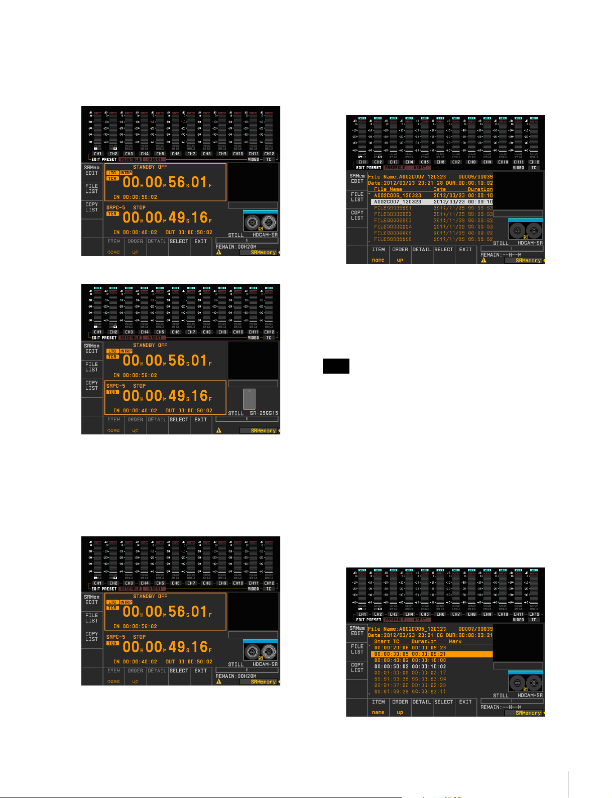
To switch between VTR mode and SRPC-5 mode
Press the RECORDER button to set to VTR mode and the
PLAYER button to set to SRPC-5 mode.
(VTR mode screen)
Displaying File Lists
Press the F2 (FILE LIST) key.
Files saved in the SRMemory card are listed in the file list.
File list operations include selecting copy files, displaying
file details, and sorting lists.
(SRPC-5 mode screen)
Displaying the Edit Screen
Press the F1 (SRMem) key.
A variety of operations can be performed in the edit screen
such as setting the IN point of the copy VTR; editing the
IN/OUT point of the copy file; selecting copy files; and
executing the copy operation.
Files in the file list are color coded as follows to show files’
copy ability which depends on format status.
White background: Currently selected file (can be
copied)
Yellow text: File can be copied
Grey text: File cannot be copied
Note
Grey text with a white background indicates a file that
cannot be copied.
To arrange the file list display
Press any of the keys detailed below.
F6 (ITEM): Switches between file name/date/recorded
time order.
F7 (ORDER) key: Switches between UP (ascending order)
and DOWN (descending order).
To view detailed information about files in the file
list
Press the T or t key to switch between the following
detailed information screens.
(File Name/Date/Duration)
VTR Video Data Operations
27
Page 28
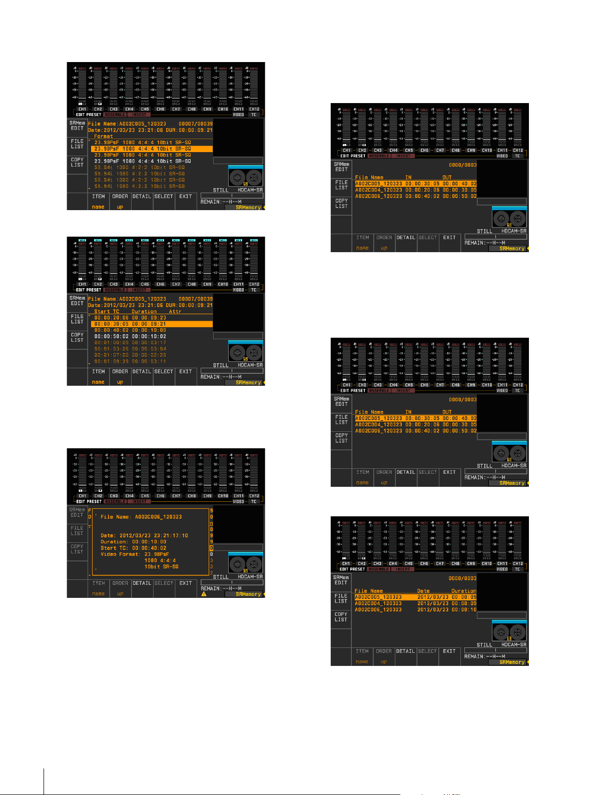
(Format)
(Start TC/Duration/Attr)
Displaying Copy Lists
Press the F3 (COPY LIST) key.
Files to be copied from the SRMemory card to the VTR are
listed in the copy list.
To view detailed information about files in the
copy list
Press the T or t key to switch between the following
detailed information screens.
(File Name/IN/OUT)
You can also display detailed information by pressing the
F8 (DETAIL) key to display a pop-up window or by
pressing the R or r key and turning the MULTI CONTROL
knob.
Press the F8 (DETAIL) or F10 (EXIT) key to close the
pop-up window and return to the file list.
(File Name/Date/Duration)
28
VTR Video Data Operations
Page 29
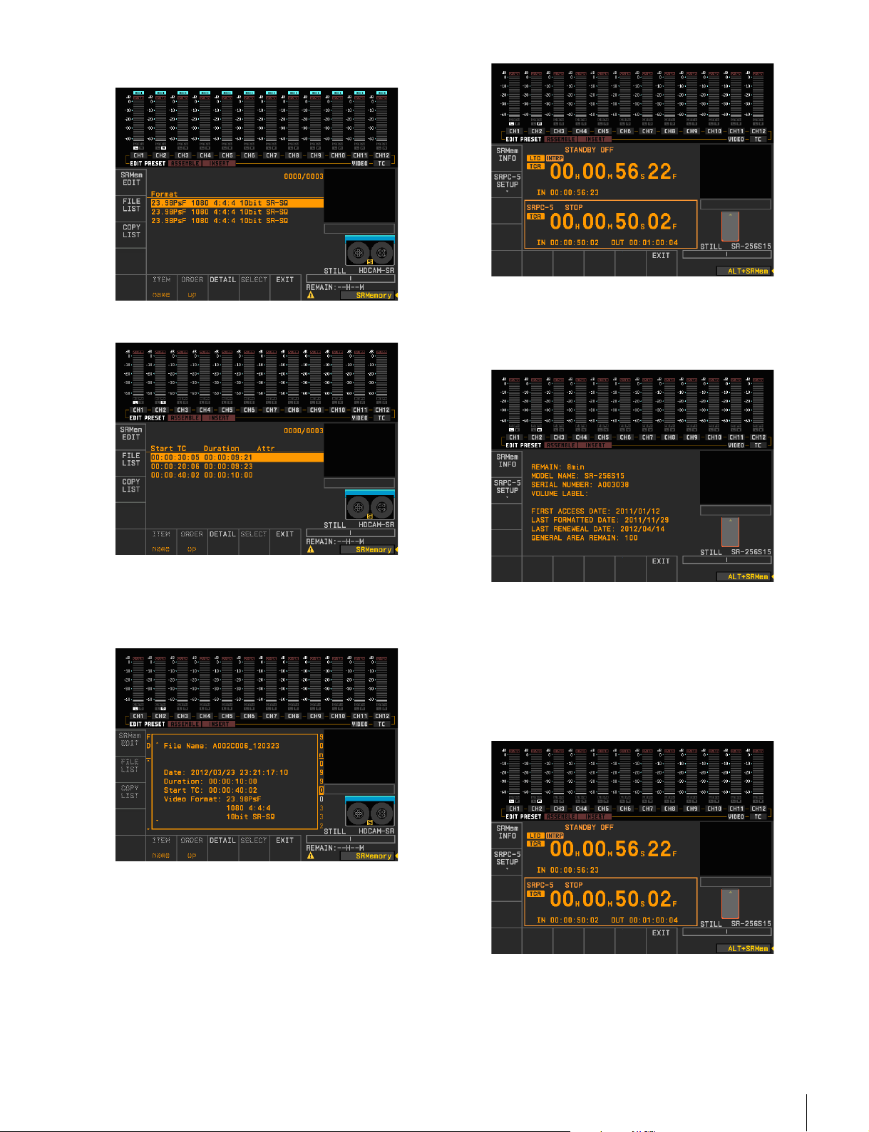
(Format)
(Start TC/Duration/Attr)
2
Press the F1 (SRMem INFO) key.
Detailed information about the SRMemory card
inserted in the SRPC-5 appears.
You can also display detailed information by displaying a
pop-up window by pressing the F8 (DETAIL) key and
pressing the R or r key and turning the MULTI CONTROL
knob.
Press the F8 (DETAIL) or F10 (EXIT) key to close the
pop-up window and return to the file list.
Viewing Detailed SRMemory Card
Information
1
Press the ALT button in the SRMemory menu to open
the ALT+SRMem menu.
Press the F10 (EXIT) key to return to the original
screen.
Changing settings for the SRPC-5
1
Press the ALT button in the SRMemory menu to
display the ALT+SRMem menu.
2
Press the F2 (SRPC-5 SETUP) key to display the
SRPC5 SETUP menu.
VTR Video Data Operations
29
Page 30
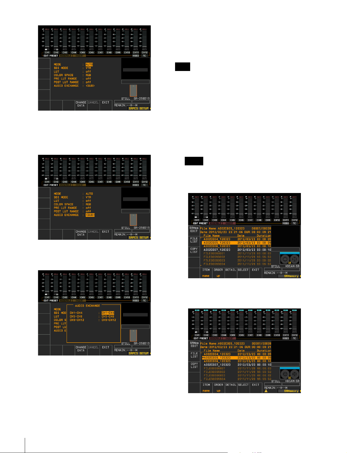
3
Press the R or r key or turn the MULTI CONTROL
knob to highlight the setting you want to change.
To configure an item for which <SUB> is
displayed
To restore previous settings
Press the F9 (CANCEL) key.
Executing copy
Note
Confirm the following before copying.
- Ensure that the REMOTE NETWORK 2 button in the
VTR is lit.
- Ensure that “B01:NW I/O MODE” in the VTR SETUP
menu is set to “SRPC”.
1
Press the F2 (FILE LIST) key in the SRMemory menu
to display the file menu.
2
Press the R or r key or turn the MULTI CONTROL
knob to highlight the file you want to copy.
Memo
You can scroll through files in groups of 100 by
holding down the SFT key while turning the MULTI
CONTROL knob.
Press the t key to display sub-window, and press the
R or r key or turn the MULTI CONTROL knob to
highlight the setting item you want to change.
To close the sub-window
Press the T key or F10 (EXIT) key.
4
Press the F8 (CHANGE DATA) key.
To configure the field value
Press the center key.
3
Press the F9 (SELECT) key.
“*” appears next to the selected clip.
4
Repeat steps 3 and 4 to select multiple clips.
30
VTR Video Data Operations
Page 31
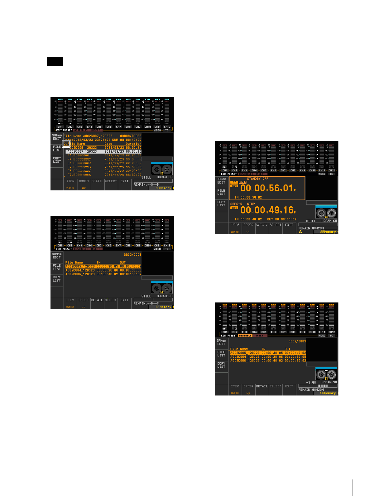
To select all files displayed in the list
Press the F9 (SELECT) key while holding down the
SFT key.
Note
Selecting all files is enabled after obtaining data (when
the “retrieving data” sign disappears) on files in the
SRMemory card.
To view a selected file list
Press the F2 (COPY LIST) key.
To set the IN point of the VTR using numeric
keys
1 Press the RECORDER button to set to
RECORDER mode.
2 Input the timecode in the scratchpad using numeric
keys.
3 Press the SET key.
4 Press the VIDEO IN key.
To set the current timecode as a IN point of
the VTR
1 Press the RECORDER button to set to
RECORDER mode.
2 Simultaneously press the ENTRY key and VIDEO
IN key.
The File No. of the files being copied and the total
selected files appear.
To delete individual files from the list
1 Press the R or r key or turn the MULTI CONTROL
knob to highlight the file you want to delete.
2 Press the CLR key.
To delete all files from the list
Simultaneously press the SFT key and CLR key.
To edit the IN/OUT point in copy files
See “Editing the Copy File IN/OUT Point” on page
32.
5
Press the F1 (SRMem EDIT) key to open the edit
screen.
7
Press the REC/EDIT button.
Copy starts.
To confirm the copy progress status
Press the F3 (COPY LIST) key. The copy list appears
so the File No. of the files being copied can be
confirmed.
When copying is complete, the file changes to a
shaded display.
6
Set the IN point of the copy VTR.
VTR Video Data Operations
31
Page 32
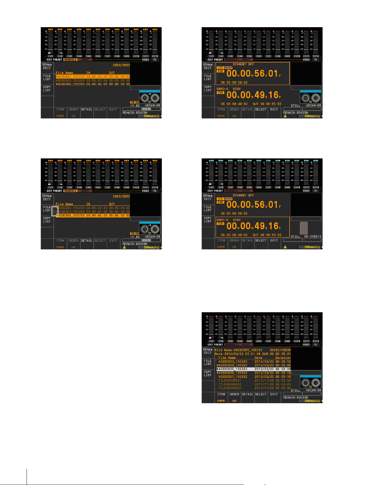
If an SRW-5800 channel condition error (VIDEO
DATA ERROR or AUDIO DATA ERROR) occurs
during copying, “!” appears to the left of the
corresponding file.
2
Press the PLAYER button to set to SRPC-5 mode.
The timecode and IN/OUT point of the SRMemory
card’s current file appears.
To confirm the copy execution log
The copy execution log is saved to the memory stick
as a csv file.
Storage directory:
MSSONY/PRO/VTR/SRW5800/copylog
File name:
“LABEL_ID (label ID for Tele-File)”_”DATE
(save date: YYMMDD)”.csv
Saved information:
IN point, OUT point, recording format, file
creation date and time, file name, device that
created the file and its serial number
To stop the copying process
Press the STOP button.
8
When copying is complete, press the F10 (EXIT) key.
This returns the screen to the file list display.
Editing the Copy File IN/OUT Point
1
Press the F1 (SRMem EDIT) key in the SRMemory
menu to open the edit screen.
To change the current file
1 Press the F2 (FILE LIST) key to display the file list.
2 Press the R or r key or turn the MULTI CONTROL
knob to highlight the file you want to make the
current file.
3 Press the center key. The file selected as the current
file is highlighted in white.
3
Change the IN (OUT) point.
32
VTR Video Data Operations
Page 33
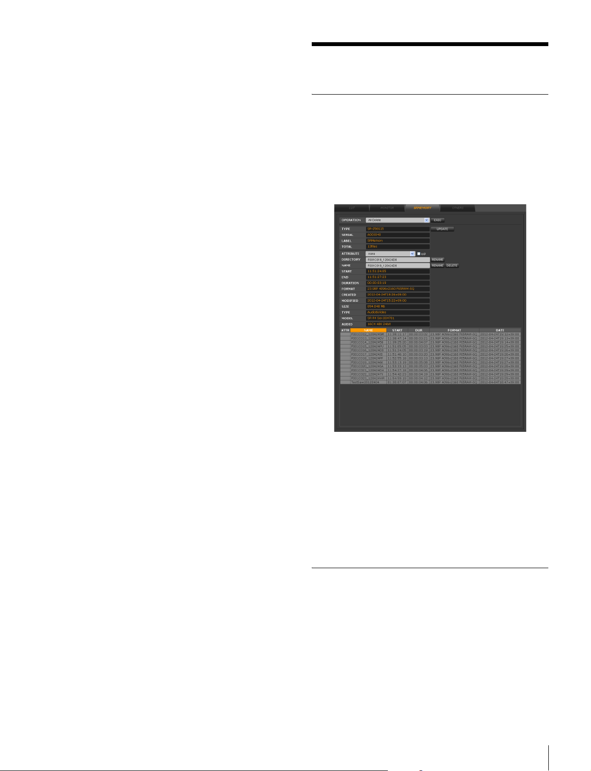
To change the IN (OUT) point using numeric
keys
1 Input the timecode in the scratchpad using numeric
keys.
2 Press the SET key.
3 Press the VIDEO IN (VIDEO OUT) key.
To make the current timecode the IN (OUT)
point
1 Turn the search dial in jog or shuttle mode to search
for the edit point.
2 Simultaneously press the ENTRY key and VIDEO
IN (VIDEO OUT) key.
To change the IN (OUT) point in frames
Simultaneously press the VIDEO IN (VIDEO OUT)
key and + or – key.
Every time you press the + or – key the edit point
advances or returns by a single frame.
To return the changed IN (OUT) point to its
original position
Simultaneously press the CLR key and VIDEO IN
(VIDEO OUT) key.
4
Press the F9 (SELECT) key.
Other Operations
Editing and Viewing SRMemory Card Information
When you click the SRPC SETUP menu button in the web
application screen and click the SRMEMORY tab, media
information on the SRMemory card inserted in the unit’s
SRMemory slot is displayed, in addition to a list of files
stored on the memory card.
The file with the edited IN/OUT point is selected as the
copy file.
To view a selected file list
Press the F2 (COPY LIST) key.
In addition to viewing SRMemory card information, you
can also perform the following operations.
All Delete: Deletes all files in the SRMemory
FORMAT: Formats the SRMemory
ATTRIBUTE: Specifies OK / NG / KEEP attributes for
each file
WP: Sets write protection for each file
NAME: Changes file names
DELETE: Deletes files
Viewing File Server Data
You can view the directories and files stored on the shared
file server by accessing the DISK CONTROL tab from the
HOME or IMPORT menu.
Other Operations
33
Page 34
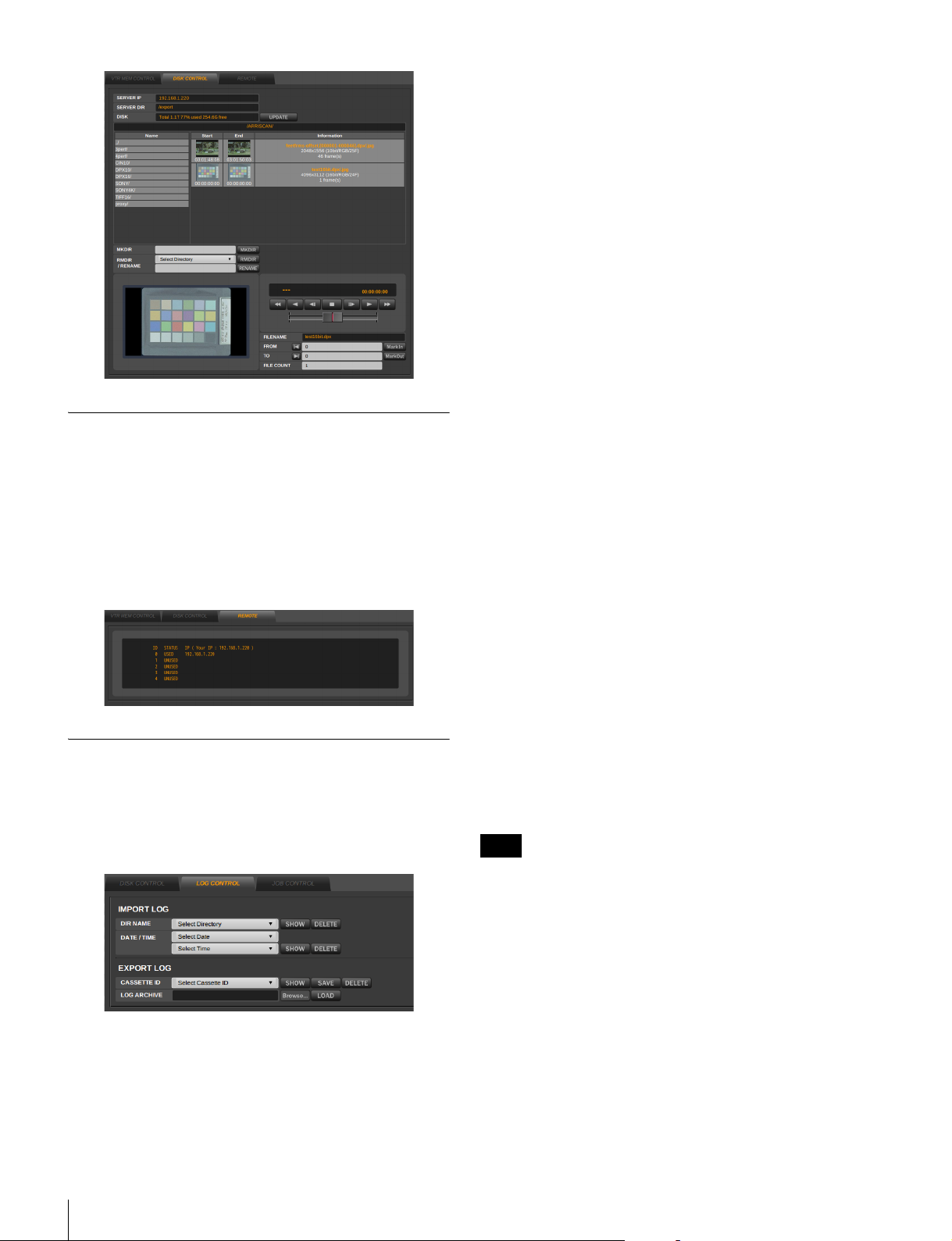
Displaying the Web Client IP
Managing import log files
To display an import log file
1
Select the import log file using one of the following
methods.
• Specify the directory name of the log file in the DIR
NAME field.
• Specify the date and time the log file was saved in
the DATE/TIME field.
2
Click the SHOW button for the DIR NAME or DATE/
TIME field.
The selected log file appears.
To delete an import log file
1
Select the import log file in the DIR NAME or DATE/
TIME field.
Addresses
You can view the IP addresses of the web clients that are
currently accessing the unit.
To do so, click the HOME menu button in the web
application screen, and click the REMOTE button.
The IP addresses of all the web clients appear in the
REMOTE tab screen.
Managing Log Files
You can manage the import log files.
To do so, click the DISK SETUP menu button in the web
application screen, and click the LOG CONTROL tab to
display the LOG CONTROL tab screen.
2
Click the DELETE button for the DIR NAME or
DATE/TIME field.
The selected log file is deleted.
Managing export log files
You can manage export log files stored in the log directory
(Log Dir) of the mounted file server.
To display an export log file
Specify the cassette ID of the log file in the CASSETTE ID
field, and click the SHOW button.
To copy an export log file to a web client
Specify the drive or removable media on the web client
machine, specify the cassette ID of the log file in the
CASSETTE ID field, and then click the SAVE button.
The selected export log file and a thumbnail directory are
copied as a tar.gz file.
Note
The thumbnail directory is only created when the LOG
PROXY setting is set to [Copy to Log Directory] in the
DISK CONTROL tab screen of the EXPORT menu.
34
Other Operations
To save an export log file on a web client to the
file server
1
Click the [Browse…] button of the LOG ARCHIVE
field, and specify the export log file stored on a drive
or removable media on the web client machine.
2
Click the LOAD button of the LOG ARCHIVE field.
The log file is saved to the log file directory (Log Dir)
of the mounted file server.
Page 35
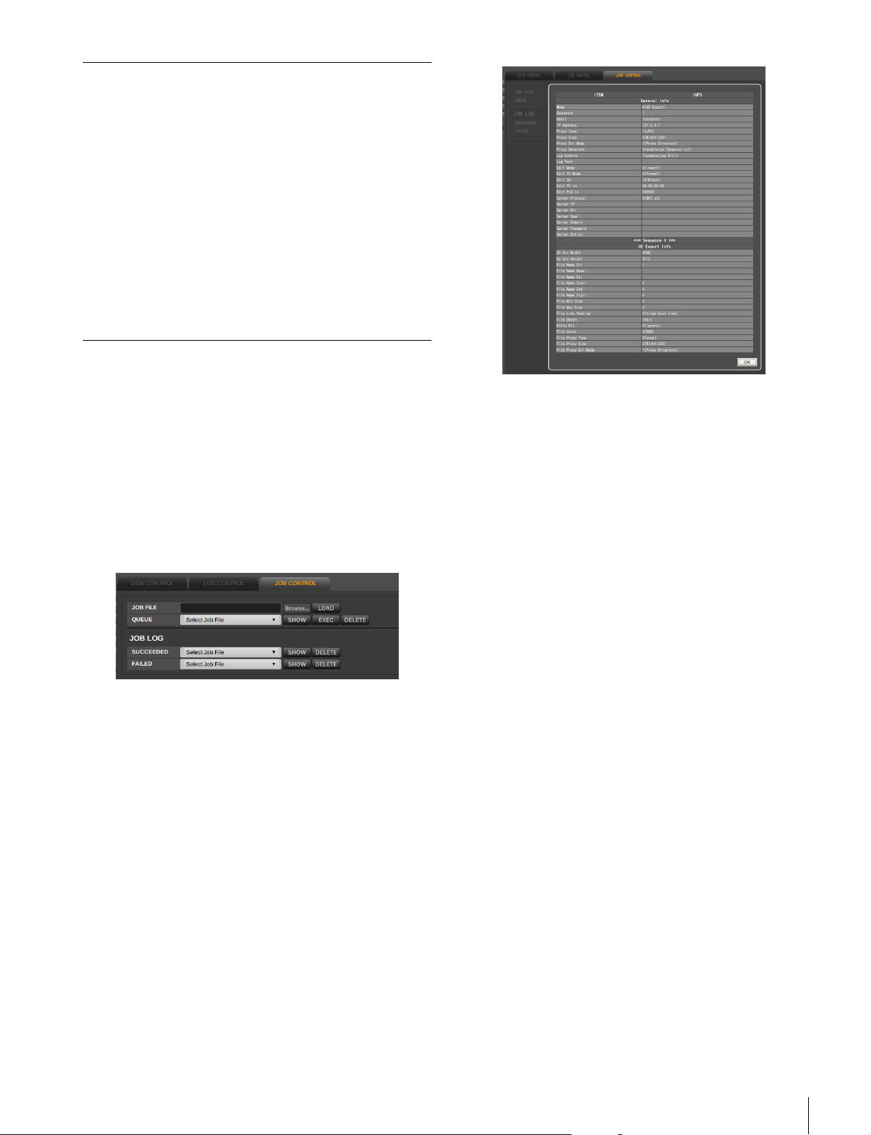
Using Export Log Files
When a tape created via exporting at one facility includes
an export log file and is handed over to another facility, the
facility that receives the tape can open the export log file
and view the clips that are recorded on the tape.
In addition, specific clips can be imported to the clip list by
clicking the IMP button in the export log screen. By using
this function, you can specify only the clips you need from
the clips recorded on the tape during import.
For details, refer to the operating instructions for the
HKSR-5804.
Automatic Execution Using a Job File
Operations such as importing can be automatically carried
out by loading an XML-format job file that you create with
an external editor.
Click the DISK SETUP menu select button on the web
application, and then click the JOB CONTROL tab.
You can load or delete a job file, check its contents,
execute it, and check the results in the JOB CONTROL tab
screen.
Loading a job file
Click the [Browse...] button to the right of the JOB FILE
box in the JOB CONTROL tab screen, specify the job file
stored on the web client disk or external media, and then
click the LOAD button.
Job files that have been loaded can be selected in the
QUEUE box.
Checking the contents of a job file
In the QUEUE box, select the job file that you want to
check, and then click the SHOW button.
The contents of the selected job file are displayed.
Executing a job file
In the QUEUE box, select the job file that you want to
execute, and then click the EXEC button.
The contents of the selected job file are automatically
executed.
Checking the results of an automatic
execution
Log files for job files that have been automatically
executed are stored in the JOB LOG area, each indicated
by the name of job file appended by the date and time of
execution. A log file of a successfully executed job file can
be selected by clicking the SUCCEEDED box, while a log
file of a job file that failed can be selected by clicking the
FAILED box.
After selecting the log file that you want to check its
contents, click the SHOW button to display the contents.
To delete a log file
Select the log file that you want to delete, and then click the
DELETE button.
Deleting a job file
In the QUEUE box, select the job file that you want to
delete, and then click the DELETE button.
About creating a job file
To create a job file using the settings configured in the web
application, configure import settings and other settings in
the IMPORT menu, and then click the START button
while holding down the Shift key. A job file is created
without import taking place.
Other Operations
35
Page 36
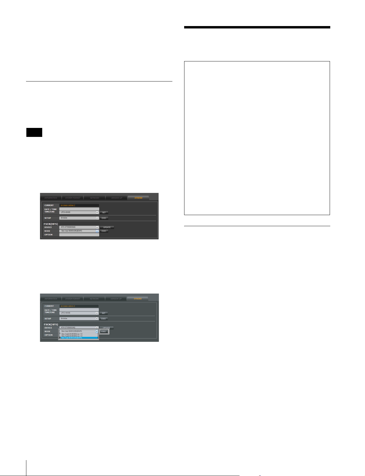
The tasks that can be defined in a job file correspond with
most of the items that can be specified in the menus of the
web application.
For details, see “Job File Samples” on page 41 in
“Appendix”.
Checking File Systems (FSCK)
The file system of an HDD connected to the unit by
eSATA can be checked and restored by following the
below steps.
Note
The HFS+ file system is the only HDD format that can be
checked and restored.
1
Click the DIAGNOSIS menu button in the web
application screen, and then click the OTHERS tab.
The OTHERS tab screen appears.
Specifications
Notes
• Always make a test recording, and verify that it was
recorded successfully.
SONY WILL NOT BE LIABLE FOR DAMAGES OF
ANY KIND INCLUDING, BUT NOT LIMITED TO,
COMPENSATION OR REIMBURSEMENT ON
ACCOUNT OF FAILURE OF THIS UNIT OR ITS
RECORDING MEDIA, EXTERNAL STORAGE
SYSTEMS OR ANY OTHER MEDIA OR
STORAGE SYSTEMS TO RECORD CONTENT OF
ANY TYPE.
• Always verify that the unit is operating properly before
use. SONY WILL NOT BE LIABLE FOR
DAMAGES OF ANY KIND INCLUDING, BUT
NOT LIMITED TO, COMPENSATION OR
REIMBURSEMENT ON ACCOUNT OF THE LOSS
OF PRESENT OR PROSPECTIVE PROFITS DUE
TO FAILURE OF THIS UNIT, EITHER DURING
THE WARRANTY PERIOD OR AFTER
EXPIRATION OF THE WARRANTY, OR FOR
ANY OTHER REASON WHATSOEVER.
2
Select the node to perform the file check from
“NODE” in the FSCK (HFS) field, and then click the
EXEC button.
When the file check is complete, a results screen like
the one below appears.
SRPC-5
General
Power supply 100 to 240 V AC (50/60 Hz)
Power consumption
110 W (with all options installed)
Inrush current
(1) Maximum possible inrush current at
initial switch-on (Voltage changes
caused by manual switching):
28 A peak, 1.7 A r.m.s. (240 V AC)
(2) Inrush current after a mains
interruption of five seconds (Voltage
changes caused at zero-crossing):
5 A peak, 1.6 A r.m.s. (240 V AC)
Operating temperature
5°C to 40°C (41°F to 104°F)
Storage temperature
–20 °C to +60 °C (–4 °F to +140 °F)
Mass 10 kg (22 lb.)
Dimensions 427 × 43.6 × 546 mm (16
1
21
/2 in.) (W×H×D)
Input connectors
AUX INPUT A/B: BNC (2)
HD SDI (1.485 Gbps) (conforming to
SMPTE-292M/372M, BTA-S004B)
3G SDI (2.97 Gbps) (SMPTE-424M)
7
/8 × 1 3/4 ×
36
Specifications
Page 37

Output connectors
AUX OUTPUT A/B: BNC (2)
HD SDI (1.485 Gbps) (conforming to
SMPTE-292M/372M, BTA-S004B)
3G SDI (2.97 Gbps) (SMPTE-424M)
I/O connectors
VTR I/F (IN, OUT)
Local I/F INPUT A/B: BNC (2)
Local I/F OUTPUT A/B: BNC (2)
NETWORK 1000Base-T modular jack (1)
OPTION PCI Express Slot (1) (PCI Express x4
Gen1)
Supported formats
See “Supported Formats” on page 39.
On-board functions
1D LUT, downconverter, color space converter
Confirmed operational environment
Browser Firefox, Internet Explorer, Safari,
Google Chrome
NFS server Redhat Linux E5, Mac OS v10.6
CIFS server Windows XP, Windows 7
Supplied accessories
Rack mount angle (1 each for left and right)1)
Washers (4)
Screws (4)
Installation manual (1)
Operation guide (1)
Operation manual (1)
1)
An optional RMM-10 Rack Mount Kit is necessary to
mount the unit on a rack.
Dimensions 88 × 250 × 231 mm (3
1
9
/8 in.) (W×H×D) (excluding
protrusions)
1
/2 × 97/8 ×
Output connectors
MONITOR BNC (1)
HD SDI (1.485 Gbps) (conforming to
SMPTE-292M, BTA-S004B)
3G SDI (2.97 Gbps) (SMPTE-424M)
NETWORK 1000Base-T modular jack (1)
Option PCI Express Slot (1) (PCI Express x4
Gen1)
Supported formats
See “Supported Formats” on page 39.
On-board functions
1D LUT, downconverter, color space converter
Confirmed operational environment
Browser Firefox, Internet Explorer, Safari, Google
Chrome
NFS server Redhat Linux E5, Mac OS v10.6
CIFS server Windows XP, Windows 7
Supplied accessories
AC adapter (1)
Rubber feet (4)
Installation manual (1)
Operation guide (1)
Operation manual (CD-ROM) (1)
Design and specifications are subject to change without
notice.
Design and specifications are subject to change without
notice.
SR-PC4
General
Power supply 19.5 V
Currnet consumption
5 A (with all options installed)
Operating temperature
5°C to 35°C (41°F to 95°F)
Storage temperature
–20°C to +60°C (–4°F to +140°F)
Mass 3.9 kg (8 lb. 10 oz.)
Specifications
37
Page 38
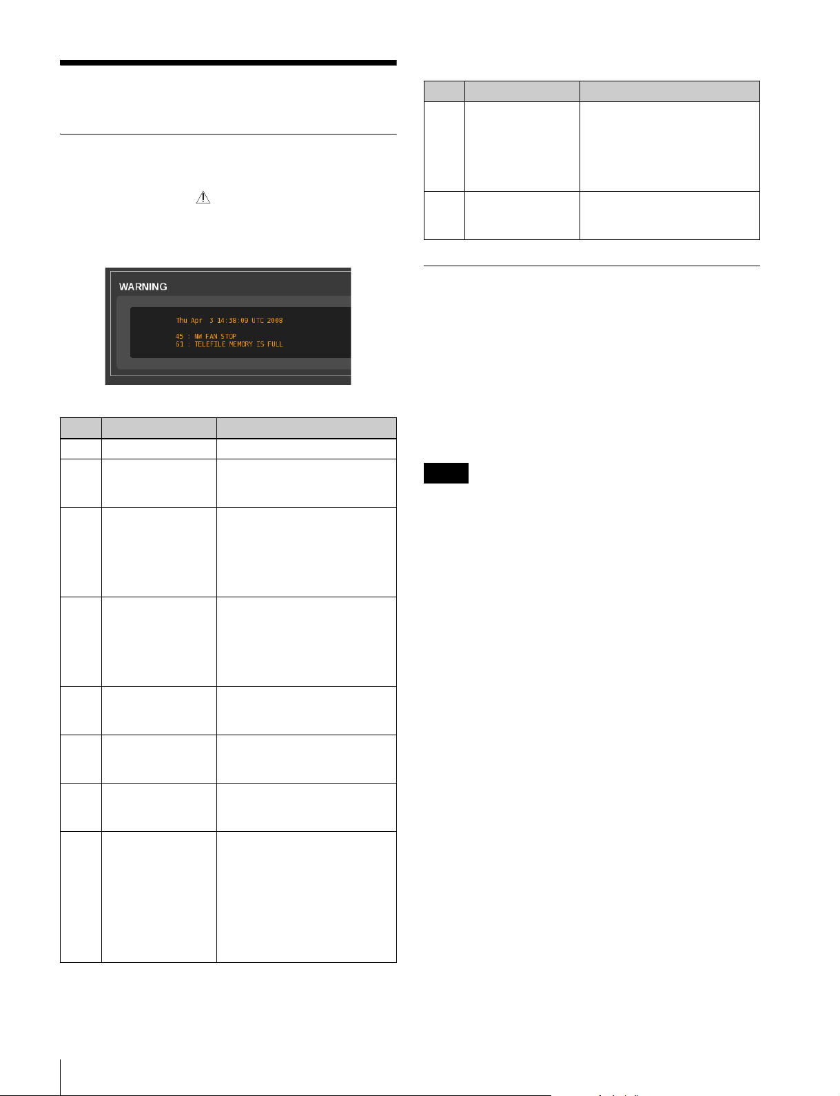
Warning messages
Appendix
Error/Warning Messages
When an abnormality is detected on the unit or VTR, a
yellow warning mark ( ) flashes to the left of the
timecode (or picture ID) in the MEM CONTROL window
or VTR CONTROL window. Clicking the warning mark
displays the message as follows.
Error messages
Code Message Description
03 FAN STOP A fan error was detected.
04 POWER FAN
STOP
81 EPR PLD1 INITIAL
ERROR
82 EPR PLD2 INITIAL
ERROR
83 CN PLD1 INITIAL
ERROR
83 DC PLD1 INITIAL
ERROR
84 DM INTERFACE
ERROR
88 NVRAM
CHECKSUM
ERROR
[PC5] An error was detected
with the fan located in the
power section.
[PC5] A PLD1 initialization error
was detected for the EPR-3
board.
[PC4] A PLD1 initialization error
was detected for the EPR-4
board.
[PC5] A PLD2 initialization error
was detected for the EPR-3
board.
[PC4] A PLD2 initialization error
was detected for the EPR-4
board.
[PC5] A PLD1 initialization error
was detected for the CN-3367
board.
[PC4] A PLD1 initialization error
was detected for the DC-161
board.
A communication error was
detected between the DM-145
and CPU.
An NVRAM (IC310) checksum
error was detected. IP address
and other configuration data
may be damaged.
Restart the unit using the
factory default settings
(IP address: 192.168.0.1;
subnet mask: 255.255.255.0;
MTU: 1500).
Code Message Description
11 EPR PLD1
TEMPERATURE
HIGH
12 DM PLD1
TEMPERATURE
HIGH
[PC5] A PLD1 temperature
error was detected for the
EPR-3 board.
[PC4] A PLD1 temperature
error was detected for the
EPR-4 board.
A PLD1 temperature error was
detected for the DM-145 board.
Salvaging SRMemory Cards for which File Content was Lost
The unit incorporates a salvage function that is designed to
minimize data loss for SRMemory cards for which file
content was lost. The salvage function restores files based
on factors such as the maker information recorded on the
SRMemory card. The salvaging process can take as little
as a few seconds or up to 60 minutes, depending on the
conditions at the time recording was interrupted.
Notes
• The salvage function is intended to salvage as much
recorded material as possible in the event of an
unforeseen accident, but it does not guarantee 100%
restoration of data.
• This function will not restore data recorded immediately
preceding the recording interruption. The amount of data
lost will be as follows.
SR-Lite mode: Approx. 8 seconds of data
SR-SQ mode: Approx. 4 seconds of data
• Whenever you insert an SRMemory card that requires
salvaging or turn on the unit with such a card inserted, a
message asking whether you want to perform salvaging
will appear.
• Recording and playback are disabled for SRMemory
cards that require salvaging.
• When you format an SRMemory card, the memory card
will be ready for use immediately. However, any
previously recorded data will be lost.
To restore files via salvaging
1
Insert the SRMemory card for which file content was
lost into the SRMemory slot.
A warning massage and a message asking whether you
want to perform salvaging or formatting appear.
38
Appendix
Page 39
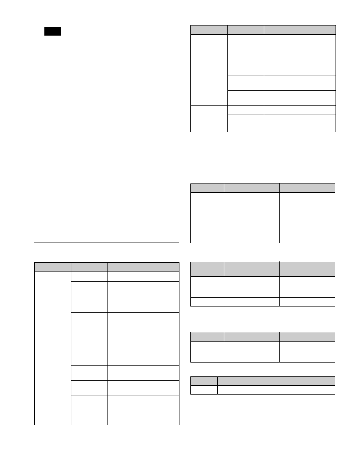
Note
After you start the salvaging process, the process
cannot be stopped. Be sure that you have enough time
to wait for the process to complete before starting.
2
Select and confirm “Salvage.”
The salvaging process starts, and the “Please wait.”
message appears.
The message closes automatically when the process is
complete.
If files are not restored after salvaging
If an SRMemory card cannot be restored even after
salvaging, you can format the SRMemory card to make the
card usable again.
1
Insert the SRMemory card that could not be salvaged.
A warning massage and a message asking whether you
want to perform salvaging or formatting appear.
2
Select and confirm “Format.”
The formatting process starts, and the “Please wait.”
message appears.
The message closes automatically when the process is
complete.
Category Key Function
Importing
operations
DISK SETUP
operations
a) Make sure that the cursor is not in the text field when you press the key.
Ctrl+\ Previews the selected clip.
Ctrl+A Adds the selected sequence
to the import list.
Ctrl+C Starts importing.
ESC Cancels importing.
Shift+
double-click
Crtl+
double-click
Ctrl+U Updates the file list.
Ctrl+Shift+M Mounts the NFS server.
Ctrl+Shift+U Unmounts the NFS server.
Selects all files.
Clears selection of all files.
Supported Formats
SRMemory
Resolution Playback mode System frequency
1080 4:2:2Lite (2D/3D),
4:2:2SQ (2D/3D),
4:4:4SQ (2D/3D),
4:4:4HQ
F65RAW F65RAW SQ,
F65RAW Lite
F65RAW HFR 23p, 24p, 25p, 29p
23.98PsF, 24PsF,
25PsF, 29PsF, 50i,
59.94i, 50p, 59p
23.98p, 24p, 25p,
29p, 50p, 59p
List of Keyboard Shortcuts
Category Key Function
File control
operations
Menu/tab
control
operations
a)
J
a)
K
a)
L
a)
T
t
Space bar
Ctrl+Shift+H Opens the HOME menu.
Ctrl+Shift+I Opens the IMPORT menu.
Ctrl+Shift+V [PC5] Opens the VTR
Ctrl+Shift+P Opens the PROXY SETUP
Ctrl+Shift+D Opens the DISK SETUP
Ctrl+T Moves to the next tab
Ctrl+Shift+T Moves to the previous tab
REV/REW
PAU S E
PLAY/FFWD
STEP REV
STEP FWD
a)
PAUSE/PLAY
SETUP menu.
menu.
menu.
screen.
screen.
VTR
Resolution Record and
playback modes
1080 422, 4:4:4SQ,
4:4:4HQ
720 4:2:2 50p, 59.94p
System frequency
23.98PsF, 24PsF,
25PsF, 29PsF, 30PsF,
50i, 59.94i, 60i
Formats that can be copied from SRMemory to
tape
Resolution
1080 4:2:2Lite, 4:2:2SQ,
Playback mode
4:4:4SQ (2D)
System frequency
23PsF, 24PsF, 25PsF,
29PsF, 50i, 59i, 50p,
59p
File formats
Typ e Format
MXF 4:2:2Lite, 4:2:2SQ, 4:4:4SQ (SRMemory format)
Appendix
39
Page 40

LUT File Formats Applicable to This Board
Examples of the five lookup table (LUT) file formats
applicable to this board are shown below.
Note
Line numbers (“Lx” in the tables below) do not appear in
the actual LUT files.
LUT file type 1: R, G, and B have the same value
(the same curve)
“LUT: 1 1024” in the header indicates one output data
block (common to R, G, and B) corresponding with the 10bit (1024) input data.
The bit depth of the output is determined by the maximum
output value.
(This is an example of 10-bit input and 10-bit output.)
# Comment
LUT: 1 1024
# (Line No,) Output value
L1 0
L2 0
L3 1
•
•
•
L1023 1023
L1024 1023
LUT file type 2: R, G, and B have individual values
(individual curves) and are aligned vertically in
the order of R, G, B
“LUT: 3 1024” in the header indicates three separate
output data blocks (for R, G, and B) corresponding with
the 10-bit (1024) input data.
The bit depth of the output is determined by the maximum
output value.
The output values on lines L1 to L1024 are R values, the
values on lines L1025 to L2048 are G values, and the
values on lines L2049 to L3072 are B values.
(This is an example of 10-bit input and 10-bit output.)
# Comment
LUT: 3 1024
# (Line No,) Output value
L1 0
L2 0
L3 1
•
•
•
L1023 1023
L1024 1023
L1025 0
L1026 0
L1027 1
•
•
•
L2047 1023
L2048 1023
L2049 0
L2050 0
L2051 0
•
•
•
L3071 1022
L3072 1023
LUT file type 3: R, G, and B have individual values
(individual curves) and are aligned horizontally
“LUT10” in the header indicates the bit depth of the output
is 10 bits.
The bit depth of the input is determined by the maximum
number of lines.
(This is an example of 10-bit input and 10-bit output.)
# Comment
LUT10
# (Line No,) Input
value
L1 0 2 2 2
L2 1 2 2 2
L3 2 2 2 2
L1023 1022 1023 1023 1023
L1024 1023 1023 1023 1023
Output R Output G Output B
•
•
•
40
Appendix
Page 41

LUT file type 4: R, G, and B have individual values
(individual curves) and are aligned horizontally
The bit depth is not indicated in the header. It is
automatically determined by the number of lines and their
values.
(This is an example of 10-bit input and 10-bit output.)
# Comment
# (Line No,) Input
value
L1 0 2 2 2
L2 1 2 2 2
L3 2 2 2 2
L1023 1022 1023 1023 1023
L1024 1023 1023 1023 1023
LUT file type 5: R, G, and B have individual values
(individual curves) and are aligned horizontally
The bit depth is not indicated in the header. It is
automatically determined by number of lines and their
values.
There are no lines for input values.
(This is an example of 10-bit input and 10-bit output.)
# Comment
# (Line No,) Output R Output G Output B
L1 2 2 2
L2 2 2 2
L3 2 2 2
L1023 1023 1023 1023
L1024 1023 1023 1023
Output R Output G Output B
•
•
•
•
•
•
MPEG-4 Visual Patent Portfolio License
THIS PRODUCT IS LICENSED UNDER THE MPEG-4
VISUAL PATENT PORTFOLIO LICENSE FOR THE
PERSONAL AND NON-COMMERCIAL USE OF A
CONSUMER FOR
(i) ENCODING VIDEO IN COMPLIANCE WITH THE
MPEG-4 VISUAL STANDARD (“MPEG-4
VIDEO”)
AND/OR
(ii) DECODING MPEG-4 VIDEO THAT WAS
ENCODED BY A CONSUMER ENGAGED IN A
PERSONAL AND NON-COMMERCIAL
ACTIVITY AND/OR WAS OBTAINED FROM A
VIDEO PROVIDER LICENSED BY MPEG LA TO
PROVIDE MPEG-4 VIDEO.
NO LICENSE IS GRANTED OR SHALL BE IMPLIED
FOR ANY OTHER USE. ADDITIONAL
INFORMATION INCLUDING THAT RELATING TO
PROMOTIONAL, INTERNAL AND COMMERCIAL
USES AND LICENSING MAY BE OBTAINED FROM
MPEG LA, LLC. SEE HTTP://WWW.MPEGLA.COM
MPEG LA is offering licenses for (i) manufacturing/sales
of any storage media storing MPEG-4 Visual video
information (ii) distribution/broadcasting of MPEG-4
Visual video information in any manner (such as online
video distribution service, internet broadcasting, TV
broadcasting). Other usage of this product may be required
to obtain license from MPEGLA.
Please contact MPEG LA for any further information.
MPEG LA, L.L.C., 250 STEELE STREET, SUITE 300,
DENVER, COLORADO 80206, http://www.mpegla.com
Job File Samples
Samples of job files used for automatic execution are shown below.
You can copy these samples and edit them as necessary on an external editor to create your own job files.
A comment (<!-- xxxxx -->) is indicated below each element as an explanation of the element.
Example of a comment:
<mode>1</mode>
<!-- 1:Codec Import/2:Codec Export/3:UC Import/4:UC Export/11:Memory Import -->
Appendix
41
Page 42

Note
Errors in description in a job file may result in unforeseen operations during automatic execution.
For details on actual operations related to automatic executions, see “Automatic Execution Using a Job File” on page 35.
Sample: Importing from the SRMemory card
<?xml version="1.0" encoding="UTF-8"?>
<jobinfo>
<general>
<mode>11</mode>
<!-- 1:Codec Import/2:Codec Export/3:UC Import/4:UC Export/11:Memory Import -->
<log>
<control></control>
<!-- 0:disable/*1:enable(Log Dir)/2:enable(Selected Dir) -->
<text></text>
<!-- 30 characters -->
<fcp></fcp>
<!-- *0:disable/1:enable -->
<handle></handle>
<!-- Handle value for FCP xml -->
</log>
<proxy>
<!-- Proxy Setting for GUI/AutoGen -->
<type></type>
<!-- 0:BMP/*1:JPG -->
<size></size>
<!-- 0:160/*2:320/3:640 -->
<dirmode></dirmode>
<!-- 0:Same as Main Files/*1:Proxy Directory/2:Resolution Directory -->
<gen></gen>
<!-- 0:disable/1:enable(n)/2:enable(l)/3:enable(c)/4:enable(a)/*5:enable(as Temporarily) -->
</proxy>
<abort></abort>
<!-- 0:disable/*1:enable -->
</general>
<sequence>
<!-- You can add up to 1000 sequences. -->
<memory>
<filename></filename>
<!-- File Name(used if File ID:-1) -->
</memory>
<main>
<name>
<original></original>
<!-- 0:Manual input/*1:Use Original Name -->
<dir></dir>
<!-- 128 characters(depends on full pathname) -->
<base></base>
<!-- 32 characters -->
<sid></sid>
<!-- 0:No Sub ID/*1:Add Sub ID -->
<reeldir></reeldir>
<!-- *0:disable/1:Add SRMemory ID Dir/2:Add Reel Name Dir -->
<delimitter></delimitter>
<!-- 0:'_' (Under Bar)/*1:'.' (Period)/2:'-' (Minus) -->
</name>
</main>
<audio>
<ch></ch>
<!-- 0/2/4/6/8/10/12/14/16/*255(auto) -->
</audio>
<header>
<meta></meta>
<!-- 0:Off/*1:All Data -->
<reel>
<mode></mode>
<!-- 0:Manual/1:SRMemory ID/*2:SRMemory Label -->
<name></name>
<!-- 30 characters (memid:SRMemory ID/memlabel: SRMemory Label) -->
</reel>
<tc></tc>
<!-- 0*:LTC/1:VITC/2:Recounted TC (for MXF only) -->
42
Appendix
Page 43

</header>
</sequence>
</jobinfo>
Connecting the SRPC-5/SR-PC4 to the Shared File Server and Transferring Files
To transfer files when the SRPC-5/SR-PC4 is connected to
a computer (file server), settings must be configured on the
file server. This section describes how to configure these
settings.
For details on the procedure for Windows OS servers, see
“Windows servers (Windows 7 Professional)” on page 43.
For details on the procedure for Mac OS servers, see “Mac
OS servers (Mac OS X)” on page 45.
5
Verify that the [User must change password at next
logon] check box is not selected.
6
Select the [Password never expires] check box.
7
Click the [Create] button, and click the [Close] button
after verifying the setting contents.
8
Verify that “srpc” has been created in the User folder
in the [Computer Management] dialog box.
To create the shared folder
1
Click [Computer] in the Start menu.
Windows servers (Windows 7
Professional)
The system requirements for settings configuration are as
follows.
OS: Windows 7 Professional
Connection method: Peer-to-peer between Windows 7
and the SR-PC4/SRPC-5
Network connection settings:
- IP address
• Windows 7: 192.168.0.7
• SR-PC4/SRPC-5: 192.168.0.5
- MTU = 1500
Shared folder: C:\sr_files
User account:
- User name = srpc
- Password = sony1234
To create a new user account
1
Right-click [Computer] in the Start menu, and click
[Manage].
The [Computer Management] dialog box appears.
2
Double-click the [Local Users and Groups] icon in the
left pane, and click the [User] icon.
3
Right-click an empty space in the right pane, and click
[New User].
The [New User] dialog box appears.
The [Computer] screen appears.
2
Double-click [Local Disk (C:)].
3
Click [New folder].
A new folder is created.
4
Click the new folder to highlight the file name, enter
“sr_files,” and then press the Enter key.
5
Right-click the “sr_files” folder, and click [Share
with].
The [File Sharing] dialog box appears.
6
Click the drop-down button and select the previously
created user name, “srpc.”
When the [File Sharing] dialog box returns, verify that
“srpc” has been added to the list and that the
[Permission Level] is set to [Read].
7
Click [Read] in the “srpc” row, and select [Read/
Write] from the drop-down list box.
8
Verify that the [Permission Level] is set to [Read/
Write] in the “srpc” row, and click the [Share] button.
9
Verify that the “sr_files” folder is specified as the
shared folder (\\Computer name\sr_files) in the [File
Sharing] dialog box, and click the [Done] button.
4
Enter the following for the [User Name], [Password],
and [Confirm password] fields.
User Name: srpc
Password: sony1234
Confirm password: sony1234
10
Right-click the “sr_files” folder on the C: drive in the
[Computer] screen, and click [Properties] in the
submenu.
The [sr_files Properties] screen appears.
Appendix
43
Page 44

11
Click the [Sharing] tab.
Verify that the “sr_files” folder is “Shared” and that
“\\Computer name\sr_files” appears for [Network
Path].
To configure network settings for Windows 7
Professional
1
Click [Control Panel] in the Start menu.
The Control Panel appears.
2
Click [Network and Internet].
3
Click [Network and Sharing Center].
4
Click [Change adapter settings].
5
Right-click [Local Area Connection], and click
[Properties] in the submenu.
6
Click [Internet Protocol Version 4 (TCP/IPv4)] to
select it in the [Local Area Connection Properties]
screen, and click the [Properties] button.
To change the initial settings of the SR-PC4/
SRPC-5
1
Open a Web browser, enter “192.168.0.5” in the
address bar, and press the Enter key.
The SR-PC4/SRPC-5 screen appears.
2
Click the [DIAGNOSIS] button.
3
Click the [NETWORK] tab, and enter the following
for [IP ADDRESS], [SUBNET MASK], and [MTU].
IP ADDRESS: 192.168.0.5
SUBNET MASK: 255.255.255.0
MTU: 1500
4
Click [SET].
5
When the confirmation message appears, click [OK].
6
Turn off the SR-PC4/SRPC-5, and then turn it on
again.
The settings are applied after the unit restarts.
7
Click the [Use the following IP address] button to
select it in the [Internet Protocol Version 4 (TCP/IPv4)
Properties] screen, and enter the following for the IP
address and subnet mask.
IP address: 192.168.0.7
Subnet mask: 255.255.255.0
8
Click [OK].
To verify the network connection between the
SR-PC4/SRPC-5 and Windows 7
First, verify that the SR-PC4 or SRPC-5 is connected to the
Windows workstation via an Ethernet cable (CAT-5E),
and then verify the connection status between the SR-PC4/
SRPC-5 and Windows 7 Professional using a ping
command. Verify using the ping command as follows.
1
Enter “cmd” in the [Search programs and files] box of
the Start menu, and press the Enter key.
The DOS screen appears.
2
Enter “ping 192.168.0.5” and press the Enter key.
If the connection is properly established, “Reply from
192.168.0.5” appears.
If there is a problem with the connection, “Request
time out” appears.
To mount the shared folder
1
Open a Web browser, enter “192.168.0.1” (factory
default value) in the address bar, and press the Enter
key.
2
After connection is established, click the [DISK
SETUP] button.
3
Select “CIFS” in the [DISK SETUP] screen, and enter
the following for [SERVER IP], [SERVER DIR],
[USER NAME], and [PASSWORD].
SERVER IP: 192.168.0.7
SERVER DIR: sr_files
USER NAME: srpc
PASSWORD: sony1234
4
Click the [MOUNT] button.
A confirmation screen appears.
5
To verify whether the shared folder is properly
mounted, enter a directory name in the [MKDIR] box,
and click the [MKDIR] button.
Verify that the entered directory name has been
created and appears in the list.
44
Appendix
Page 45

Mac OS servers (Mac OS X)
The system requirements for settings configuration are as
follows.
OS: Mac OS X 10.6.8
Connection method: Peer-to-peer between the Mac
workstation and the SR-PC4/SRPC-5
Network connection settings:
- IP address
• Mac OS X: 192.168.0.9
• SR-PC4/SRPC-5: 192.168.0.4
- MTU = 1500
Shared folder: /Users/sony/SR_Files
User account:
- User name = sony
- Password = srpc4
To verify the login user account privileges
1
Click the [System Preferences] icon.
2
Click the [Users & Groups] icon.
3
In the [Users & Groups] window, verify that the login
user possesses “Administrator” privileges.
To create the shared folder on the NFS
5
Click [Apply].
To configure share settings on the NFS
1
Click [Utilities] in the [Go] menu of the Finder.
2
Click the [Terminal] icon.
3
Expand the [Terminal] window display, enter “ls alg,” and press the return key.
4
Verify the access level in the “SR_File” row, enter “cd
SR_Files,” and press the return key.
5
Enter “pwd,” and press the Enter key.
6
Verify that “/Users/sony/SR_Files” appears, enter
“sudo vi /etc/exports,” and press the return key.
7
When [Password] appears, enter “srpc4” for the
password.
Use the vi text editor to create a new file in /etc/
exports/.
8
Press the i key while holding down the esc key to
switch vi to INSERT mode.
Note
This section describes how to create the shared folder in
the user’s Home. In this procedure, “sony” is specified as
the Home.
1
Click [Home] in the [Go] menu of the Finder.
2
When the content of the “sony” folder appears, click
[New Folder] in the [File] menu.
3
Click the “SR_Files” folder to select it.
4
Click [Get Info] in the [File] menu, and change the
[everyone] privilege from [Read only] to [Read &
Write] in the [SR_Files Info] dialog box that appears.
To configure network settings
1
Click the [System Preferences] icon.
2
Click [Network].
3
Click [Ethernet] in the [Network] dialog box.
4
Enter the following for the network settings that
appear on the right.
Configure IPv4: Manually
IP Address: 192.168.0.9
Subnet Mask: 255.255.255.0
9
Enter “Users/sony/SR_Files -network 192.168.0.0 mask 255.255.255.0.”
10
Press the esc key, enter “:wq!,” and press the return
key.
The file is saved.
11
Enter “more /etc/exports” after exiting the vi editor to
check the file.
12
Verify that “Users/sony/SR_Files -network
192.168.0.0 -mask 255.255.255.0” appears.
13
Enter “sudo nfsd update,” and press the return key to
restart the NFS service.
14
When [Password] appears, enter “srpc4” for the
password.
15
Enter “showmount -e,” and press the return key.
16
Verify that “/Users/sony/SR_Files 192.168.0.0”
appears.
To change the initial settings of the SR-PC4/
SRPC-5
For details on these settings, see “To change the initial
settings of the SR-PC4/SRPC-5” on page 44.
Appendix
45
Page 46

To mount the shared folder
1
Open a Web browser, enter “192.168.0.4” in the
address bar, and press the return key.
2
After connection is established, click the [DISK
SETUP] button.
3
Select [NFSv3] for [Type].
4
In the [DISK SETUP] screen, enter the following for
[SERVER IP] and [SERVER DIR].
2
When the properties appear, verify that the [everyone]
privilege in [Sharing & Permissions] is set to [Read &
Write]. If it is set to [Read Only], change the setting
[Read & Write].
3
In the [DISK SETUP] tab of the SRPC-5/SR-PC4
Web application, change [OPTION] to [force], and
click the [MOUNT] button.
The eSATA drive is mounted as “Read/Write,” and
file transfer will be possible.
SERVER IP: 192.168.0.9
SERVER DIR: /Users/sony/SR_Files
When the shared folder is mounted, the [MOUNT]
button changes to the [UNMOUNT] button.
5
To verify file reading/writing access to the shared
folder, enter “Test” in the [MKDIR] box, and click the
[MKDIR] button.
Verify that the entered directory name has been
created and appears in the list.
Notes on File Transfer
When SStP MXF files are transferred from the SRPC-5/
SR-PC4 to Windows 7 Professional, file sharing may be
damaged.
To prevent this, add the following registry values and
restart the server beforehand.
Registry hive: HKEY_LOCAL_MACHINE
Registry key: System\CurrentControlSet\Services\
LanmanServer\Parameters
Name: MaxNonpagedMemoryUsage
Type: REG_DWORD
Data value: 0xFFFFFFFF
Configuring FTP Server Settings
This section describes how to configure settings for the
FTP server on your PC.
In addition, you can improve the importing speed by
creating a file with the following content (ftp.conf file) on
the server PC in the folder to which this unit will be
mounted.
host=192.168.0.7: Enter the IP address of the server.
user=user name: Enter the FTP user name.
passwd=password: Enter the FTP password.
path=path: Enter the path from the FTP home
directory.
The content for entry differs depending on the operating
system. For details, see step 11 in “For Windows 7
Professional” or step 4 in “For Mac OS X 10.7.4”.
Note
If the FTP home directory and the shared folder are the
same, the “path” entry is not required.
For Windows 7 Professional
1
Click [Control Panel] >[Programs and Features] in the
Start menu.
Solving Problems related to eSATA HDD and SRPC-5/SR-PC4 Connections
If an eSATA HDD in HFS+ format is connected to the
SRPC-5/SR-PC4, it may be mounted as “Read Only” and
file transfer to the eSATA HDD may not be possible.
Mount the drive as “Read & Write” to enable file transfer
as follows.
1
Click the eSATA drive icon on the desktop, and select
[Get Info] in the [File] menu or press the i key while
holding down the command key.
46
Appendix
2
When the [Programs and Features] dialog box appears,
click [Turn Windows feature on and off].
3
Select the [FTP Server] check box for [Internet
Information Services] under [Turn Windows feature
on and off], and click [OK].
4
Click [Control Panel] >[Administrative Tools] in the
Start menu.
5
Click [Internet Information Services (IIS) Manager] in
the [Administrative Tools] window.
Page 47

6
Right-click the computer name that appears in the left
pane of the [Internet Information Services (IIS)
Manager] window, and click [Add FTP Site].
7
Enter a name for [FTP site name] in the [Add FTP
Site] dialog box, specify the path of the folder with
which the unit will be connected in [Physical path],
and then click [Next].
8
Click the [IP Address] drop-down button in the
[Binding and SSL Settings] dialog box, specify the
displayed IP address, select [SSL] in [No SSL], and
then click [Next].
9
Select [All Users] for [Authorization] in the
[Authentication and Authorization Information]
window, and select both the [Read] and [Write] check
boxes for [Permission].
10
Click the [Finish] button.
11
Enter the following for ftp.conf.
host=192.168.0.7
user=srpc
password=sony1234
This completes FTP server configuration for Mac OS X
10.7.4.
This completes FTP server configuration for Windows 7
Professional.
For Mac OS X 10.7.4
1
Double-click [Applications] in the Finder, doubleclick the [Utilities] icon in the [Applications] window,
and start [Terminal].
2
Enter the following commands in Terminal.
a. sudo -s
b. launchctl load -w /System/Library/
LaunchDaemons/ftp.plist
3
If the FTP home directory is different from the NFS
directory, configure the following in Terminal.
Create a symbolic link.
Example: FTP home: /Users/srpc
NFS home: /Volumes/HDD2/export
# ln -s /Volumes/HDD2/export /Users/srpc/export /
Usesrs/srpc/export
4
Enter the following for ftp.conf.
host=192.168.0.9
user=sony
passwd=srpc4
path=export
Appendix
47
Page 48

The material contained in this manual consists of information
that is the property of Sony Corporation and is intended solely
for use by the purchasers of the equipment described in this
manual.
Sony Corporation expressly prohibits the duplication of any
portion of this manual or the use thereof for any purpose
other than the operation or maintenance of the equipment
described in this manual without the express written
permission of Sony Corporation.
Trademarks
• Windows and Internet Explorer are registered trademarks of
Microsoft Corporation in the United States and/or other
countries.
• Mac OS, Safari, and Final Cut Pro are trademarks of Apple
Inc., registered in the U.S. and other countries.
• Firefox is a registered trademark of the Mozilla Foundation
in the United States and/or other countries.
• Linux is a registered trademark of Linus Torvalds in the U.S.
and other countries.
• Chrome is a trademark of Google Inc.
• Other system names, products names, and company
names appearing in this manual are trademarks or
registered trademarks of their respective holders. In this
manual, such names are not indicated by ® or TM marks.
Page 49

Sony CorporationSRPC-5 (SYL/CNC)
SR-PC4 (SYM/CN7)
4-283-628-02 (1) © 2011
 Loading...