

Sony SRM-L560 Operating Instructions Manual

4-155-648-12 (1)
LCD VIDEO MONITOR
Operating Instructions
Before operating the unit, please read this manual thoroughly
and retain it for future reference.
SRM-L560
© 2009 Sony Corporation

WARNING
To reduce the risk of fire or electric shock, do not
expose this apparatus to rain or moisture.
Using this unit at a voltage other than 120 V may require
the use of a different line cord or attachment plug, or both.
To reduce the risk of fire or electric shock, refer servicing
to qualified service personnel.
To avoid electrical shock, do not open the
cabinet. Refer servicing to qualified personnel
only.
THIS APPARATUS MUST BE EARTHED.
When installing the unit, incorporate a readily accessible
disconnect device in the fixed wiring, or connect the power
plug to an easily accessible socket-outlet near the unit. If a
fault should occur during operation of the unit, operate the
disconnect device to switch the power supply off, or
disconnect the power plug.
For the customers in the U.S.A.
This equipment has been tested and found to comply with
the limits for a Class A digital device, pursuant to Part 15
of the FCC Rules. These limits are designed to provide
reasonable protection against harmful interference when
the equipment is operated in a commercial environment.
This equipment generates, uses, and can radiate radio
frequency energy and, if not installed and used in
accordance with the instruction manual, may cause
harmful interference to radio communications. Operation
of this equipment in a residential area is likely to cause
harmful interference in which case the user will be
required to correct the interference at his own expense.
For the customers in Canada
This Class A digital apparatus complies with Canadian
ICES-003.
For the customers in Europe
This product with the CE marking complies with both the
EMC Directive and the Low Voltage Directive issued by
the Commission of the European Community.
Compliance with these directives implies conformity to
the following European standards:
• EN60950-1:Product Safety
• EN55103-1: Electromagnetic Interference (Emission)
• EN55103-2: Electromagnetic Susceptibility (Immunity)
This product is intended for use in the following
Electromagnetic Environment: E4 (controlled EMC
environment, ex. TV studio)
The manufacturer of this product is Sony Corporation, 17-1 Konan, Minato-ku, Tokyo, Japan.
The Authorized Representative for EMC and product
safety is Sony Deutschland GmbH, Hedelfinger Strasse
61, 70327 Stuttgart, Germany. For any service or
guarantee matters please refer to the addresses given in
separate service or guarantee documents.
This apparatus shall not be used in the residential area.
You are cautioned that any changes or modifications not
expressly approved in this manual could void your
authority to operate this equipment.
All interface cables used to connect peripherals must be
shielded in order to comply with the limits for a digital
device pursuant to Subpart B of Part 15 of FCC Rules.
This device complies with Part 15 of the FCC Rules.
Operation is subject to the following two conditions: (1)
this device may not cause harmful interference, and (2) this
device must accept any interference received, including
interference that may cause undesired operation.
When installing the installation space must be secured in
consideration of the ventilation and service operation.
• Do not block the ventilation slots at the top, left and right
side and rear panels.
• Leave a space around the unit for ventilation.
• Leave more than 15 cm of space in the rear of the unit to
secure the operation area.
When the unit is installed on the desk or the like, leave at
least 15 cm of space in the rear.
Leaving 15 cm or more of space above the unit is
recommended for service operation.
For the customers in Europe, Australia and New
Zealand
WARNING
This is a Class A product. In a domestic environment, this
product may cause radio interference in which case the
user may be required to take adequate measures.
For kundene i Norge
Dette utstyret kan kobles til et IT-strømfordelingssystem.
Apparatet må tilkoples jordet stikkontakt
Suomessa asuville asiakkaille
Laite on liitettävä suojamaadoituskoskettimilla
varustettuun pistorasiaan
För kunderna i Sverige
Apparaten skall anslutas till jordat uttag
2

Table of Contents
Chapter 1 Overview
Precautions ......................................................................................6
Features............................................................................................7
Options .............................................................................................9
Location and Function of Parts....................................................10
On Safety............................................................................................... 6
On Installation ....................................................................................... 6
Handling the LCD Screen ..................................................................... 6
On Cleaning........................................................................................... 6
On Repacking ........................................................................................ 7
Input/Output Connector and Adaptor.................................................... 9
Front Panel .......................................................................................... 10
Left Side Panel .................................................................................... 12
Right Side Panel .................................................................................. 13
Chapter 2 Preparations
Environments of the Installation Location ..................................14
Carrying the Monitor .....................................................................15
About the Screen Mode.................................................................15
Installing an Input Adaptor ...........................................................18
Attaching the Hooks......................................................................29
Installing Application Software (PC Application) .......................29
Connections of the Monitor and PC.............................................31
4K/QFHD Mode.................................................................................. 15
Quad View Mode ................................................................................ 16
2K/HD Zoom Mode ............................................................................ 16
Screen Modes and Applicable Setting Values .................................... 16
Number of Signal Inputs in Single Screen Mode................................ 17
Input Signal and Selectable Screen Mode........................................... 17
Installing an Input Adaptor.................................................................. 18
Connecting the Cable .......................................................................... 21
Required .............................................................................................. 29
Recommended System Requirements ................................................. 29
Installing the SRM Manager ............................................................... 30
Connecting a Monitor.......................................................................... 31
Connecting Multiple Monitors ............................................................ 32
Table of Contents
3

Turning on the Power....................................................................33
Configuring the Network...............................................................34
Starting the PC Application ..........................................................36
Settings...........................................................................................37
Adjusting ........................................................................................38
Chapter 3 Menu Window
Connecting the AC Power Cord.......................................................... 33
Turning on the Monitor ....................................................................... 33
About the IP Address .......................................................................... 34
Network Configuration for the Monitor.............................................. 34
Selecting the Area ............................................................................... 37
Setting the Input Signal ....................................................................... 38
Setting the Screen Mode of the Picture ............................................... 38
Chroma Adjustment ............................................................................ 38
Color Temperature (White Balance) Adjustment ............................... 39
Brightness/Contrast Adjustment.......................................................... 39
Displaying the Menu Window .......................................................41
Main Operation Window................................................................44
Configurations Tab Window ............................................................... 44
Controls Tab Window ......................................................................... 50
Adjustment Window ......................................................................52
Picture (Manual) Tab Window............................................................ 52
Color Temp (Auto) Tab Window........................................................ 53
Color Temp (Manual) Tab Window.................................................... 56
Display Function Window .............................................................59
User LUT Manager Tab Window ....................................................... 59
User Matrix/Gamma Tab Window...................................................... 60
Gamut Error Display Tab Window ..................................................... 61
Miscellaneous Tab Window................................................................ 63
Internal Signal Tab Window ............................................................... 64
System Configuration Window.....................................................66
Network Tab Window ......................................................................... 66
On Screen Set Tab Window ................................................................ 67
Date/Time Tab Window...................................................................... 69
Password Tab Window........................................................................ 70
File Management Window.............................................................72
Save System File Tab Window ........................................................... 72
Copy Categories Tab Window ............................................................ 73
Copy Presets Tab Window .................................................................. 75
Information Window ......................................................................77
Common Tab Window ........................................................................ 77
Screen A Tab Window ........................................................................ 78
Screen B Tab Window ........................................................................ 79
4
Table of Contents

Chapter 4 Operations
Selecting the Native Scan/Scan Mode.........................................81
Displaying the Picture in Black Detail Mode ...............................81
Displaying the Area Marker or Aspect Marker ............................82
Displaying the Audio Level Meter ................................................83
Displaying the Time Code.............................................................84
Appendixes
Specifications ................................................................................85
Input Signals and Adjustable/Setting Items................................87
Available Signal Systems .............................................................93
Available Signal Formats..............................................................95
Aperture Modification Frequency ..............................................100
Picture Display Size.....................................................................101
Picture/Frame Display.................................................................104
Matrix/Gamma Setting Table ......................................................105
Connection Combination Table When an SDI Signal Is
Format/Input Setting Table .........................................................115
Scan Mode Image ........................................................................117
Troubleshooting ..........................................................................121
Dimensions ..................................................................................127
Connection Cable Specifications for Color Temperature
Screen C Tab Window ........................................................................ 79
Screen D Tab Window ........................................................................ 80
Input .................................................................................112
Probes..............................................................................128
Menu Index 130
Table of Contents
5

Chapter 1 Overview
Overview
Precautions
On Safety
Chapter
– Leave more than 15 cm of space in the rear of the unit
to secure the operation area.
When the unit is installed on the desk or the like, leave at
least 15 cm of space in the rear.
Leaving 15 cm or more of space above the unit is
recommended for service operation.
1
• Operate the unit only with a power source as specified in
the “Specifications” section.
• A nameplate indicating operating voltage, power
consumption, etc., is located on the rear panel.
• Should any solid object or liquid fall into the cabinet,
unplug the unit and have it checked by qualified
personnel before operating it any further.
• Do not drop or place heavy objects on the power cord. If
the power cord is damaged, turn off the power
immediately. It is dangerous to use the unit with a
damaged power cord.
• Unplug the unit from the wall outlet if it is not to be used
for several days or more.
• Disconnect the power cord from the AC outlet by
grasping the plug, not by pulling the cord.
• The socket-outlet shall be installed near the equipment
and shall be easily accessible.
On Installation
• Allow adequate air circulation to prevent internal heat
build-up.
Do not place the unit on surfaces (rugs, blankets, etc.) or
near materials (curtains, draperies) that may block the
ventilation holes.
• Do not install the unit in a location near heat sources
such as radiators or air ducts, or in a place subject to
direct sunlight, excessive dust, mechanical vibration or
shock.
• When installing the installation space must be secured in
consideration of the ventilation and service operation.
– Do not block the ventilation slots at the top, left and
right side and rear panels.
– Leave a space around the unit for ventilation.
Handling the LCD Screen
• The LCD panel fitted to this unit is manufactured with
high precision technology, giving a functioning pixel
ratio of at least 99.99%. Thus a very small proportion of
pixels may be “stuck”, either always off (black), always
on (red, green, or blue), or flashing. In addition, over a
long period of use, because of the physical
characteristics of the liquid crystal display, such “stuck”
pixels may appear spontaneously. These problems are
not a malfunction.
• Do not leave the LCD screen facing the sun as it can
damage the LCD screen. Take care when you place the
unit by a window.
• Do not push or scratch the LCD monitor’s screen. Do not
place a heavy object on the LCD monitor’s screen. This
may cause the screen to lose uniformity.
• If the unit is used in a cold place, horizontal lines or a
residual image may appear on the screen. This is not a
malfunction. When the monitor becomes warm, the
screen returns to normal.
• If a fixed picture such as a frame of a divided picture or
time code, or a still picture is displayed for a long time,
an image may remain on the screen and be superimposed
as a ghosting image.
• The screen and the cabinet become warm during
operation. This is not a malfunction.
On Cleaning
Before cleaning
Be sure to disconnect the AC power cord from the AC
outlet.
6
Precautions

On cleaning the monitor screen
The monitor screen surface is especially treated to reduce
reflection of light.
As incorrect maintenance may impair the performance of
the monitor, take care with respect to the following:
• Wipe the screen gently with a soft cloth such as a
cleaning cloth or glass cleaning cloth.
If you wipe the screen using too much force, the screen
surface may lose uniformity or the LCD panel may
malfunction.
Never use tissue as it may scar the surface of the screen.
• Stubborn stains may be removed with a soft cloth such
as a cleaning cloth or glass cleaning cloth lightly
dampened with water.
• Never use solvent such as alcohol, benzene or thinner, or
acid, alkaline or abrasive detergent, or chemical cleaning
cloth, as they will damage the screen surface.
On cleaning the cabinet
• Clean the cabinet gently with a soft dry cloth. Stubborn
stains may be removed with a cloth lightly dampened
with mild detergent solution, followed by wiping with a
soft dry cloth.
• Use of alcohol, benzene, thinner or insecticide may
damage the finish of the cabinet or remove the
indications on the cabinet. Do not use these chemicals.
• If you rub on the cabinet with a stained cloth, the cabinet
may be scratched.
• If the cabinet is in contact with a rubber or vinyl resin
product for a long period of time, the finish of the cabinet
may deteriorate or the coating may come off.
Features
The SRM-L560 LCD Video Monitor incorporates the
panel that supports QFHD (3840 × 2160 pixels) of 4 times
the resolution of full HD.
This is suitable for digital cinema production, industrial
design, CG, simulation, printing, monitoring, ATC (Air
Traffic Control), research and development, videoequipment development, HD video production or GIS
(Geographic Information System) where precise image
reproduction or four-screen display is required.
The SRM-L560 features flat panel and “TRIMASTER”,
which is a new technology developed for three elements,
“accurate color reproduction,” “precision imaging” and
“quality picture consistency,” that are in demand for
professional use. “TRIMASTER” decreases the viewing
difference that occurs due to the individuality of each
panel. Also, the SRM-L560 realizes the high picture
quality and high-trust required by the color management
system with its wide color gamut device, high-resolution/
precise gradation display and signal processing of high
accuracy/calibration/feedback system.
56-type LCD panel developed for the SRM-L560
The monitor incorporates a 56-type LCD panel developed
for this monitor, which supports QFHD (4 times the
resolution of full HD) and is equipped with a 10-bit driver,
providing high resolution and high color gradation.
Chapter 1 Overview
On Repacking
Do not throw away the carton and packing materials. They
make an ideal container which to transport the unit.
Backlight system by LED with high-purity
technology
High-purity LEDs enable wider color space. The precision
backlight system also incorporates a uniformity control
function and color feedback system.
12-bit precision display engine for professional
use
The panel is equipped with a unique signal process engine
developed for the professional use monitor. This engine
incorporates 12-bit output accuracy, providing a highquality I/P conversion algorithm, scaling processing, panel
driving and a high-accuracy color management system.
Multi color space
A backlight system with high-precision technology and
color management system which uses the unique 3D LUT
(Look Up Table) reproduces the color space that complies
with the broadcast standard ITU-R BT.709, EBU and
SMPTE-C accurately. A wider color space
cinema reproductions.
1)
The RGB chromaticity of SMPTE RP 431-2 is not
covered in full.
1)
allows digital
Features
7

High-accuracy I/P conversion processing
A high-quality picture near the original one, in which
jagged lines and conversion errors are decreased by
detecting the feature of the picture inside the subdivided
block and processing properly, is reproduced.
The signal delay is decreased by judging the animation or
Chapter 1 Overview
still picture from the past video signal. Film cadence
processing, which converts the signal composed of 2-2·23·2-3-3-2 pull down to the I/P signal closely following the
original, is also selectable.
Available to a multi signal format
The monitor supports various input signals such as digital
cinema (D-Cine) 4096 × 2160/24P, 3840 × 2160/24P,
2048 × 1080/24P and variable computer signals up to
1920 × 1080. A DVI-D (HDCP correspondence) and
HDMI inputs and eight option slots are equipped as the
interface. Combination of the optional input adaptors
enables input of 3G-SDI, HD-SDI and Dual-link HD-SDI
signals.
Variable screen modes
There are three basic screen modes: 4K/QFHD, 2K/HD
Zoom and Quad View modes.
When displaying a 4096 × 2160 or 3840 × 2160 resolution
signal, 4K/QFHD mode is used.
When displaying a 2048 × 1080 or 1920 × 1080 resolution
signal in full screen, 2K/HD Zoom mode is used. Quad
View mode is used to display and confirm four HD signals
simultaneously, etc.
For details on each screen mode, see “About the Screen
Mode” on page 15.
Visual and efficient operations with a GUI
(Ethernet control
1)
)
The SRM Manager application software is used to operate
the monitor from a PC.
Operation time is shortened, as monitor operation such as
four screen settings is performed on wide GUI space
visually and efficiently.
SRM Manager
is available on Windows 7, Windows Vista
SP1 or Windows XP SP3.
1)
SRM Manager lets you control up to 32 monitors via the Ethernet
(10BASE-T/100BASE-TX).
For details of the PC requirements, see page 29.
Scan selection (Quad View mode only)/Native
scan display function
You can select from under scan (–3%), normal scan (0%)
and over scan (mask of the 5% over scan portion in the
normal scan) for the picture display.
The monitor is equipped with a native scan display
function which maps the pixel of the signal to the panel on
a one-to-one basis.
Using the shift function enables you to check every corner
of the picture.
For the operation, see “Selecting the Native Scan/Scan
Mode” on page 81.
Aspect selectable function
A squeezed and recorded signal is displayed with the
correct aspect ratio. You can select from 16:9, 1.896:1 and
1)
2.39:1
1)
aspect ratio.
When the aspect ratio is set to 2.39:1, the vertical resolution is reduced.
Safe area marker and aspect marker functions
(Quad View mode only)
The monitor is equipped with two area markers and center
marker as the safe area marker and aspect marker for
confirming the aspect ratio.
For the operation, see “Displaying the Area Marker or
Aspect Marker” on page 82.
Gamut error function
The signal outside the specified range (gamut error) caused
by the conversion of the format or during CG/CM
production can be displayed in zebra patterns.
Black detail mode display function
You can reduce dull black color caused by backlight
leaking and precisely assess any parts with low color
gradation.
You can reduce the black level to 40% of normal display
(100 cd/m
2
at 100% signal). The parts with high color
gradation (higher than 75 IRE) are clipped by the dynamic
range of the circuit. The portions to be clipped can be
displayed in zebra patterns (selectable).
For the operation, see “Displaying the Picture in Black
Detail Mode” on page 81.
Closed caption display function (except 4K/
QFHD mode)
EIA/CEA-608 or EIA/CEA-708 standard closed caption
signals superimposed on the SDI signals can be displayed
by installing the optional input adaptor (BKM-244CC).
Audio level meter and time code display
functions
Audio level of the embedded audio and time code signals
superimposed on the SDI signals can be displayed by
installing the optional input adaptor (BKM-250TG).
Variable picture adjustment functions
The white balance can be automatically adjusted by using
a commercially available probe (Konica Minolta CA-210,
DK-Technologies PM5639/06, X-Rite Eye-One Pro).
Other features
• The color temperature is selectable from D65, D93, D61,
D56, D-Cine and User.
• Built-in test patterns can be displayed; 100% white
signal, 20% gray signal, 0% black signal, PLUGE
(Picture Line Up Generation Equipment) signal, colorbar signal, 5-step gray scale signal and lamp signal.
8
Features
Options
Input adaptors
The connector panel of the monitor is composed of the
connectors on the optional input adaptors installed in the
input option slots on the side panel of the monitor. Four or
eight adaptors can be installed.
The input signal type for each connector of the adaptor is
set with the Configurations tab window of the Main
Operation window, in accordance with the configuration
of the connector panel.
Note
When installing the adaptor, be sure to perform the
necessary input setup in Input of the Configurations tab
window of the Main Operation window. If the setup is not
performed, the adaptors may not function correctly.
For information about the Configurations tab window of
the Main Operation window, see page 44.
For details of each input adaptor, refer to the operating
instructions of each model.
BKM-250TG 3G/HD/SD-SDI Input Adaptor
A decoder for serial digital component signals is built in.
Time code and audio level of the embedded audio signals
superimposed on the SDI signals can be displayed. Input/
output connectors consist of two channels of serial digital
input and two channels of monitor output.
Notes
• The signal from the MONITOR OUT connector of the
BKM-250TG does not satisfy the ON-LINE signal
specifications.
• For use of the MONITOR OUT connector in 2K/HD
Zoom mode, connect a coaxial cable less than 1 m (3.3
feet) long. For how to connect the cable, see page 23.
Caution
When you install the following input adaptor to this
equipment, use that with the serial numbers given below.
• BKM-243HS with serial number 2108355 or higher
BKM-243HS: The equipment may not meet the
requirements of the electromagnetic interference standard
or work correctly, or you may not be satisfied with the
performance if designated input adaptors are not installed.
Input/Output Connector and Adaptor
Chapter 1 Overview
BKM-243HS HD/D1-SDI Input Adaptor
A decoder for serial digital component signals is built in
and the input/output connectors consist of two channels of
serial digital signal input and one channel of monitor
output.
Notes
• The signal from the MONITOR OUT connector of the
BKM-243HS does not satisfy the ON-LINE signal
specifications.
• For use of the MONITOR OUT connector in 2K/HD
Zoom mode, connect a coaxial cable less than 1 m (3.3
feet) long. For how to connect the cable, see page 23.
BKM-244CC HD/SD-SDI Closed Caption
Adaptor
A decoder for serial digital component signals is built in.
EIA/CEA-608 or EIA/CEA-708 standard closed caption
signals superimposed on the SDI signals are decoded and
displayed. Input/output connectors consist of two channels
of serial digital input and one channel of monitor output.
Notes
• The signal from the MONITOR OUT connector of the
BKM-244CC does not satisfy the ON-LINE signal
specifications.
• For use of the MONITOR OUT connector in 2K/HD
Zoom mode, connect a coaxial cable less than 1 m (3.3
feet) long. For how to connect the cable, see page 23.
By adding the optional input adaptors, the input/output
connector panel can be assembled in a wide variety of
configurations. Acceptable signals of each adaptor are
given in the following table. The type of signal to be
applied to each input/output connector is set with the
Configurations tab window of the Main Operation
window.
For information about the Configurations tab window of
the Main Operation window, see page 44.
Input adaptor
Input signal
Single-link HD-SDI aa
Dual-link HD-SDI a(2) a
input
Single-link 3G-SDI a
Serial digital
Number of digital inputs 2 2
a: Signal can be reproduced.
a(2): Two adaptors of the same model are used.
BKM-243HS/
244CC
BKM-250TG
For details, see “Available Signal Formats” on page 95.
Options
9
Location and Function of Parts
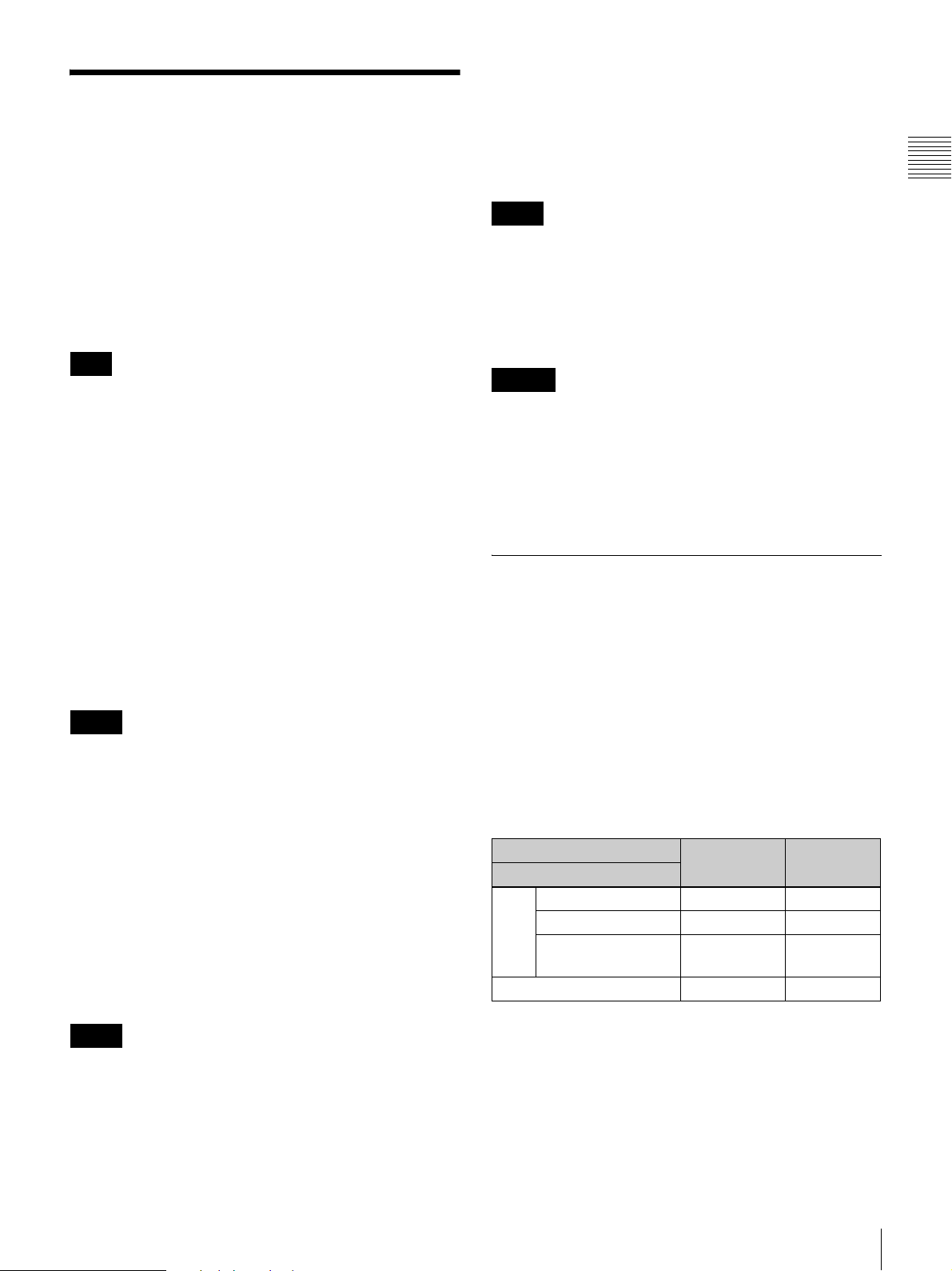
Front Panel
Chapter 1 Overview
1 OPERATE lamp
2 STATUS lamp
a OPERATE lamp
Lights in red when the monitor is in standby mode. The
monitor will be in standby mode under the following
condition:
• The monitor is changed from operation mode to standby
mode by clicking the 1 STANDBY button in the
window of SRM Manager.
Lights in green when the monitor is put into operation
mode from standby mode by clicking the 1 STANDBY
button again.
Notes
• When the lamp is flashing in red, the monitor cannot be
put into operation mode. (Internal data initialization is
taking place.) Wait until the lamp is steadily lit.
• The lamp may show the error, warning or operation
mode.
For details, see “Error/warning/operation mode display
by the lamp” on page 10.
b STATUS lamp
The lamp may show the error, warning or operation mode.
3 OVER RANGE lamp
c OVER RANGE lamp
Lights in orange when the picture is displayed in black
detail mode or when the dynamic range of the following
item is exceeded.
• Contrast (Contrast)
Flashes when the luminance is decreased to protect the
monitor from a rise in temperature.
Note
The lamp may show the error, warning or operation mode.
For details, see “Error/warning/operation mode display
by the lamp” on page 10.
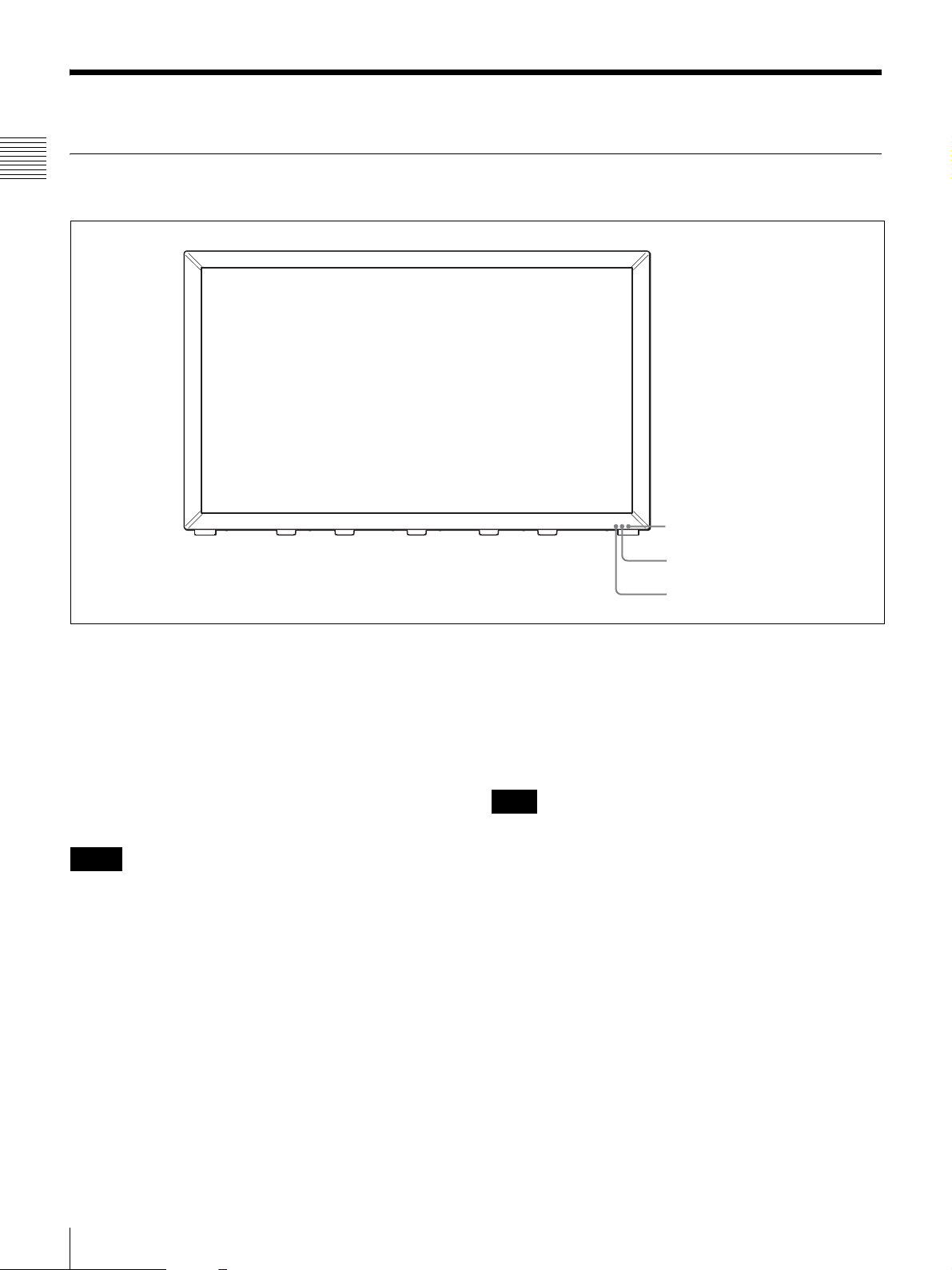
Error/warning/operation mode display by
the lamp
The OVER RANGE lamp, STATUS lamp or OPERATE
lamp on the front panel may show an error, warning or
operation mode while the monitor is being operated.
Error display
If the error is shown, please contact your Sony dealer.
For details, see “Error/warning/operation mode display
by the lamp” on page 10.
10
Location and Function of Parts
OVER
RANGE
lamp
Lights in
orange
Flashes
in orange
Goes out
Goes out
Goes out
Lights in
orange
Lights in
orange
Goes out
Lights in
orange
Lights in
orange
STATUS
lamp
Goes out
Goes out
Lights in
blue
Flashes in
blue
Flashes in
blue
Lights in
blue
Goes out
Lights in
blue
Flashes in
blue
Flashes in
blue
OPERATE
lamp
Flashes in
red
Flashes in
red
Flashes in
red
Flashes in
red
Flashes in
green
Flashes in
red
Flashes in
green
Flashes in
green
Flashes in
green
Flashes in
red
Symptoms
The power in the LED
backlight part is
overcurrent.
The power in the LED
backlight part is
overvoltage.
The LED temperature of
the LED backlight part is
unusual.
The LED driver
temperature of the LED
backlight part is unusual.
The temperature sensor
is unusual.
The temperature of the
LCD panel is unusual.
The RGB sensor of the
LED backlight part is
unusual.
LED disconnection of the
LED backlight part.
The LED V
voltage in the LED
backlight part is unusual
F feedback range over).
(V
The power consumption
is unusual.
F power
Chapter 1 Overview
Warning/operation mode display
OVER
RANGE
lamp
Flashes
in orange
Lights in
orange
–: Status except for error display.
STATUS
lamp
OPERATE
lamp
––
––
The luminance is reduced
to protect the circuit from
an increase of
temperature in the LED
backlight part.
g Please contact your
Sony dealer.
• The dynamic range of
the LED backlight part
is exceeded.
gPlease contact your
Sony dealer.
• The dynamic range is
exceeded when
contrast is adjusted.
g Reduce the contrast
setting.
• The picture is displayed
in black detail mode.
Symptoms
Location and Function of Parts
11
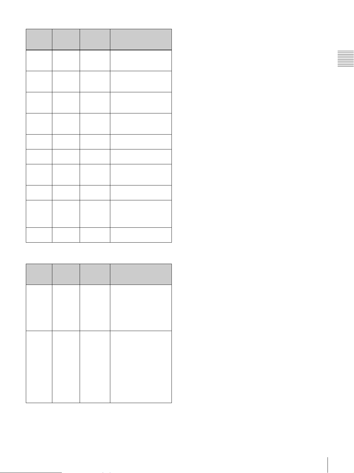
Left Side Panel
Chapter 1 Overview
1 OPTION A connector
2 OPTION B connector
3 LAN (10/100) connector
4 NETWORK switch
5 OPTION C connector
6 Input option slots
7 DVI-D input connector
8 HDMI input connector
a OPTION A connector
Used to connect a probe for automatic adjustment.
b OPTION B connector
Used for future expansion.
The cover is attached at the factory.
c LAN (10/100) connector (10BASE-T/100BASE-
TX)
Connect to the network or the LAN (10/100) connector of
the PC by using a 10BASE-T/100BASE-TX LAN cable
(not supplied).
Input block A
Input block B
Input block C
Input block D
CAUTION
• For safety, do not connect the connector for peripheral
device wiring that might have excessive voltage to this
port. Follow the instructions for this port.
• The effective communication throughput may be
affected by the network system.
d NETWORK switch
LAN: To connect to the network.
PEER TO PEER: To connect to the LAN (10/100)
connector of the PC in one-to-one connection.
Note
12
Set the NETWORK switches on input blocks A to D of the
monitor to the same setting. Otherwise, the monitor may
Location and Function of Parts
not be connected to SRM Manager and the correct picture
may not be displayed.
To input the DVI signal of SXGA or higher resolution, use
the cable within 3 m (118
1
/8 inches) in length.
e OPTION C connector (D-sub 9-pin)
Used for future expansion.
The cover is attached at the factory.
f Input option slots
Used to install the optional input adaptors.
For installing the input adaptor, see page 18.
For the input signals, see “Input/Output Connector and
Adaptor” on page 9.
g DVI-D (DVI digital) input connector
Inputs DVI Rev.1.0 applicable Single-link digital RGB
signal.
Right Side Panel
h HDMI input connector
Inputs the HDMI signal.
HDMI (High-Definition Multimedia Interface) is an
interface that supports both video and audio on a single
digital connection, allowing you to display high quality
digital picture. The HDMI specification supports HDCP
(High-bandwidth Digital Content Protection), a copy
protection technology that incorporates coding technology
for digital video signals.
Notes
• The monitor does not support the HDMI audio signal.
• Use HDMI compliant cable (not supplied), Category 2
(High Speed HDMI cable), with HDMI logo.
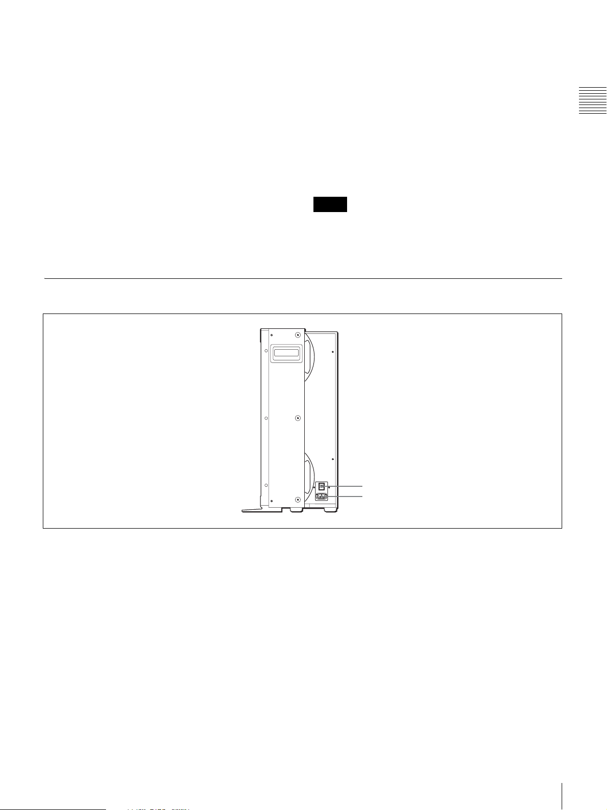
Chapter 1 Overview
a MAIN POWER switch
When turned on (?), the monitor enters operation mode.
b AC IN connector (3-pin)
Connects the monitor to an AC power source, via the
supplied AC power cord.
1 MAIN POWER switch
2 AC IN connector
Location and Function of Parts
13
Preparations
Chapter 2 Preparations
Chapter
Environments of the Installation Location
2
Illumination environments
The apparent color reproduction on the monitor is greatly
affected by ambient light or glare.
The LCD device controls the brightness by moving LCD
molecules with the backlight always lit. For this reason, in
a dark place, an LCD monitor screen shows very dim light
leaks from the black image. We recommend that you
adjust the ambient light and use in an environment that
does not degrade the reproduction of black.
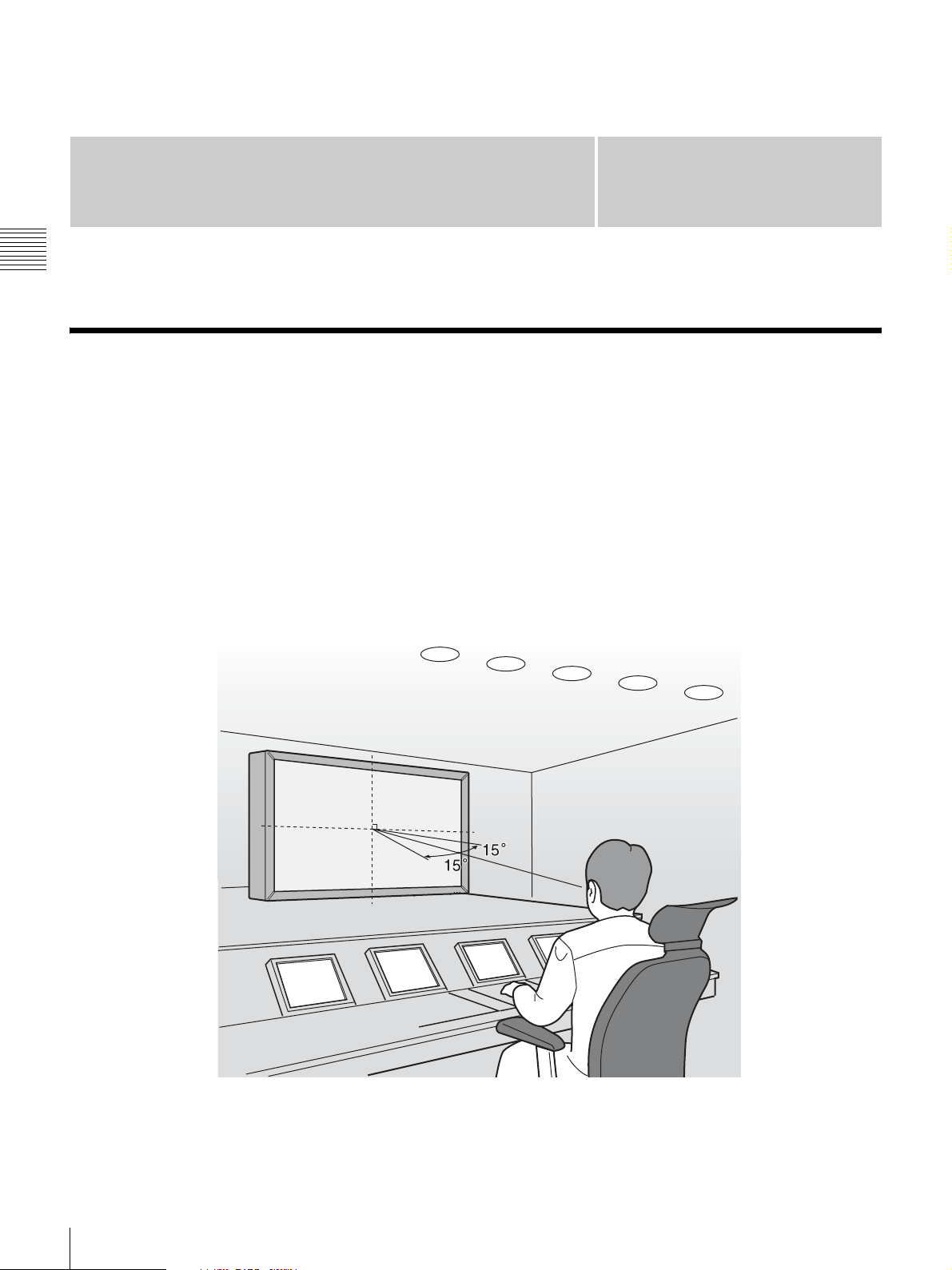
Viewing angle
The ideal viewing angle is within 5 degrees (up/down/left/
right) off the center of the monitor screen when the
operator views the entire monitor screen. Keep the viewing
angle within 15 degrees off the center of the monitor
screen.
14
Environments of the Installation Location
Carrying the Monitor
About the Screen Mode
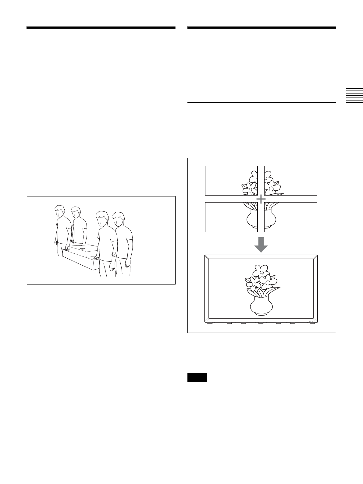
Carry or move the monitor in the proper
manner
• When the monitor is carried or moved in an improper
manner, it may fall and cause serious injuries such as
bruises or bone fractures, or be damaged leading to
malfunction of the monitor.
• As the monitor is heavy, unpack or carry it with at least
four people.
• Hold the monitor securely as illustrated.
• Never expose the monitor to strong shock. Dropping it
may cause serious personal injury or damage to the
monitor.
• Never hold or press the LCD screen strongly.
• Unplug the AC power cord and connecting cables from
the monitor.
When the monitor is carried with the cord and cables
connected, the power cord be damaged and later may
cause fire or electric shock.
You can select the mode from three screen modes
according to the type of the input signal or monitoring use.
Input the signal with the specified connections (page 21).
Click the corresponding screen mode button (page 42) to
select the screen mode.
Chapter 2 Preparations
4K/QFHD Mode
Select to confirm the 4096 × 2160 or 3840 × 2160
resolution signal.
One screen of 4K or QFHD is displayed with the signals
divided in four.
• The mass of this unit is approx. 73 kg (160 lb 15 oz).
Install the unit on a horizontal, flat rack in such a manner
that the rack will not become deformed or break.
For restrictions on the screen mode, see “4K/QFHD
mode” in “Input Signals and Adjustable/Setting Items” on
page 87.
Notes
• When displaying in 4K/QFHD mode, all the input
signals from the inputs A to D should be genlocked to
synchronize with one another. Also, input all the input
signals in the same signal system and signal format.
• When interlaced signals are input from the four inputs A
to D and combined to display one image, a horizontal
line may appear on the border of four divided screens
owing to the process of I/P conversion.
Carrying the Monitor / About the Screen Mode
15
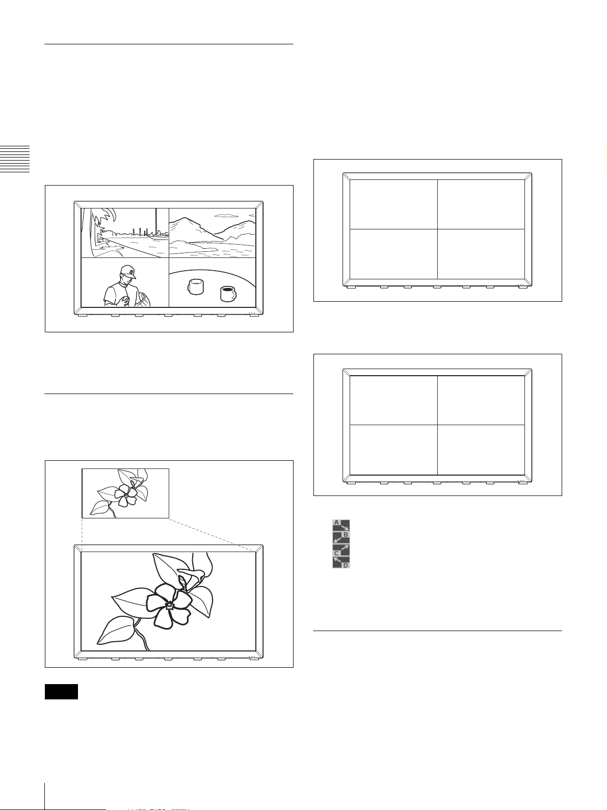
Quad View Mode
Select when a 2048 × 1080, 1920 × 1080 or 1280 × 720
resolution signal or computer signal is input.
It is useful to compare pictures for how color or gradation
is processed or pictures shot from various angles such as
front, rear or left/right side. Also, this mode is used to
confirm overscan of an HD signal or picture position by
the marker or to compare HD-SDI and DVI signals of the
Chapter 2 Preparations
same picture.
For restrictions on the screen mode, see “Quad View
Mode” in “Input Signals and Adjustable/Setting Items” on
page 89.
• When interlaced signals are input from the four inputs A
to D and combined to display one image, a horizontal
line may appear on the border of four divided screens
owing to the process of I/P conversion.
About the magnified screen
When the BKM-250TG is used
The screen A is magnified.
A
When the BKM-243HS or BKM-244CC is used
You can select a screen to be magnified from among
screens A, B, C and D.
2K/HD Zoom Mode
Select to confirm the 2048 × 1080, 1920 × 1080 or 1280 ×
720 resolution signal in full display mode.
Notes
• 2K/HD Zoom mode is not available for the DVI or
HDMI signal input.
A
C
Click the radio button for the screen you wish to magnify.
: To magnify the A signal
: To magnify the B signal
: To magnify the C signal
: To magnify the D signal
For restrictions on the screen mode, see “2K/HD Zoom
Mode” in “Input Signals and Adjustable/Setting Items” on
page 91.
B
D
Screen Modes and Applicable Setting Values
There are some setting items that apply to every mode and
every screen and others that apply only to the particular
mode or screen for which the item is set.
16
About the Screen Mode

Common setting items
The setting values of the items in the following table apply
to every mode and every screen.
Setting values Menu windows
Adjustment values for Picture
Preset data (Contrast/Bright/
Chroma)
Preset/Manual selection for
Contrast/Bright/Chroma
adjustments
Contrast/Bright/Chroma manual
adjustment values
Color Temp adjustment values and
related settings
Adjustment values for Marker
Preset data
Matrix and Gamma settings for
User Matrix/Gamma user data
File to be registered in User LUT
data and its registration number
Black Detail mode settings
(including On/Off setting)
Gamut Error settings (including On/
Off setting)
Network settings (including SNMP
setting)
Date/time setting System Configuration >
Password setting System Configuration >
First layer > Second
layer
Adjustment > Picture
(Manual) tab
Main Operation > Controls
tab
Main Operation > Controls
tab
Adjustment > Color Temp
(Auto) tab and Color Temp
(Manual) tab
Main Operation >
Configurations tab
(Edit of Marker Preset)
Display Function > User
Matrix/Gamma tab
Display Function > User
LUT Manager tab
Display Function >
Miscellaneous tab
Display Function > Gamut
Error Display tab
System Configuration >
Network tab
Date/Time tab
Password tab
Settings other than common setting items
Values set for 4K/QFHD mode and values set
for Quad View mode or 2K/HD Zoom mode
The values set for 4K/QFHD mode are not reflected to
Quad View or 2K/HD Zoom mode. The values set for
Quad View or 2K/HD Zoom mode are not reflected to 4K/
QFHD mode.
Set the items other than common setting items for 4K/
QFHD mode and for Quad View or 2K/HD Zoom mode
individually.
4K/QFHD
mode
Common setting items
Setting
items for
4K/QFHD
mode
Quad View and 2K/HD Zoom mode
Setting
items for
screen A
Setting
items for
screen B
Setting
items for
screen C
Setting
items for
screen D
Number of Signal Inputs in Single Screen Mode
The table below shows the number of available signal
inputs when a screen mode is not switched.
When you are using a combination of screen modes, see
“Input Signal and Selectable Screen Mode.”
Required
Input
signal
Input
adaptor
number
of
adaptors
3G-SDI BKM-250TG
Dual-
HD-SDI
HD-SDI
HDMI – – 1 1 to 4 –
–: Not available
a)
Use the same model of the adaptor.
BKM-250TG
link
BKM-243HS
BKM-244CC
BKM-250TG
BKM-243HS
BKM-244CC
DVI – – 1 1 to 4 –
a)
a)
4 1 to 2 1 to 8 1 to 2
8 1 to 4 1 to 16 1 to 4
411 to 41
821 to 82
8 1 to 2 1 to 8 1 to 4
4 1 to 2 1 to 8 1 to 2
8 1 to 4 1 to 16 1 to 4
4 1 to 2 1 to 8 1 to 4
8 1 to 4 1 to 16 1 to 8
Note
Number of inputs
4K/
QFHD
Quad
View
2K/HD
Zoom
When one signal is input, you can select Quad View mode.
However, the screens with no signal received are displayed
in black.
Input Signal and Selectable Screen Mode
Chapter 2 Preparations
Values set for Quad View mode and values set
for 2K/HD Zoom mode
The values set for Quad View mode apply to 2K/HD Zoom
mode, as well.
The settings for Quad View mode and 2K/HD Zoom mode
are required for each screen A to D. Set the items other
than common setting items for screen A, B, C and D
individually.
Input
signal
3G-SDI
Dual-link
HD-SDI
HD-SDI
DVI
4K/QFHD Quad View 2K/HD Zoom
a)
a
b)
a
a)
a
c)
a
d)
a
e)
a
d)
a
a –
About the Screen Mode
a)
a
b)
a
a)
a
17
–: Not available
a)
b)
c)
d)
Chapter 2 Preparations
e)
Input
signal
HDMI
At least four input adaptors are required. Use the same model of the input
adaptor.
When the BKM-243HS or BKM-244CC input adaptor is used, prepare
eight and when the BKM-250TG is used, prepare four. Use the same
model of the input adaptor.
When no sync signals are input to four inputs, the display screen becomes
no sync.
One input adaptor is required for each input block.
Two input adaptors are required for each input block when the BKM243HS or BKM-244CC is used and one input adaptor is required when the
BKM-250TG is used. Use the same model of the input adaptor.
4K/QFHD Quad View 2K/HD Zoom
c)
a
a –
Installing an Input Adaptor
Installing an Input Adaptor
Each input adaptor can be installed in any input option slot
on the side panel.
Caution
Combination of the connection when an
SDI signal is input
To display the picture of an SDI signal, you can select
various combinations of the model or number of input
adaptors or Single-link or Dual-link connection. You may
not be able to configure the required combination of the
connection. Select the proper combination according to the
system in use.
For details on combination patterns, see “Connection
Combination Table When an SDI Signal Is Input” on page
112.
When you install the following input adaptor to this
equipment, use that with the serial numbers given below.
BKM-243HS with serial number 2108355 or higher
BKM-243HS: This equipment may not meet the
requirements of the electromagnetic interference standard
or work correctly, or you may not be satisfied with the
performance if designated input adaptors are not installed.
Note
Turn off the MAIN POWER switch of the monitor and
disconnect the AC power cord before installing or
removing adaptors.
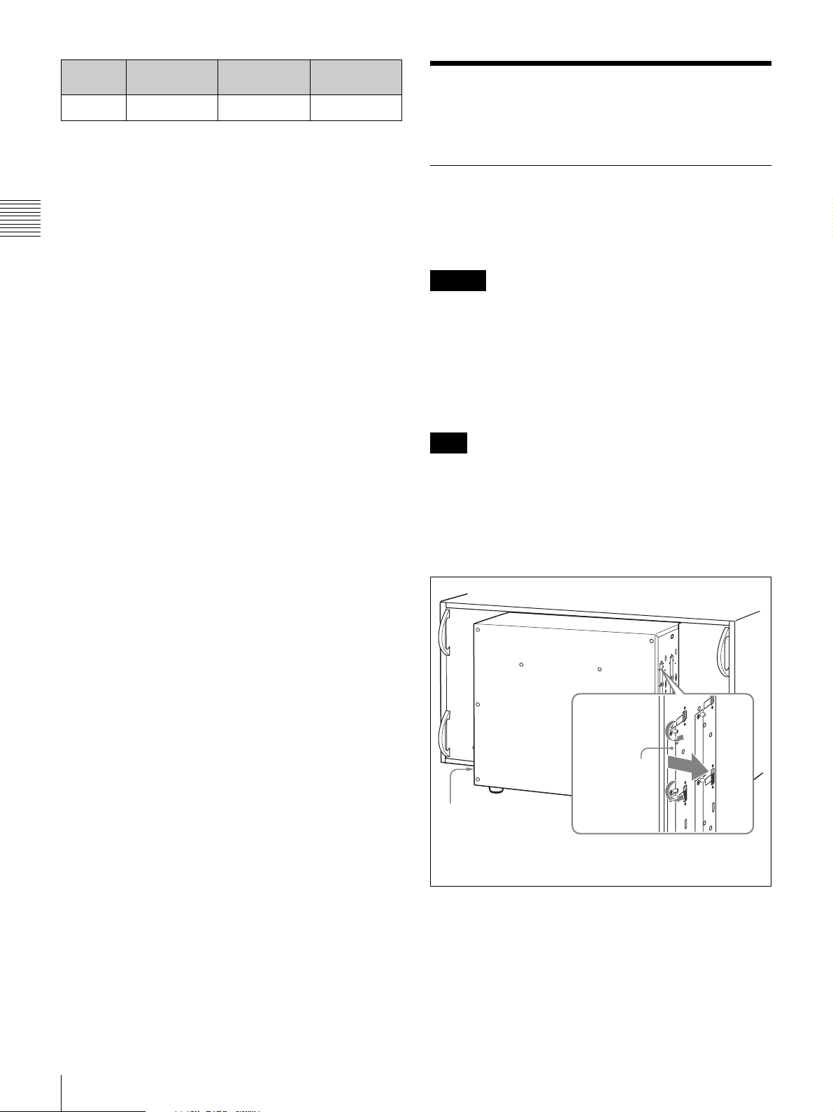
1
Loosen two screws and remove the cover of an input
option slot on the side panel of the monitor.
18
Installing an Input Adaptor
Cover of an
input option slot
Make sure the MAIN
POWER switch is turned
off, and disconnect the
AC power cord.
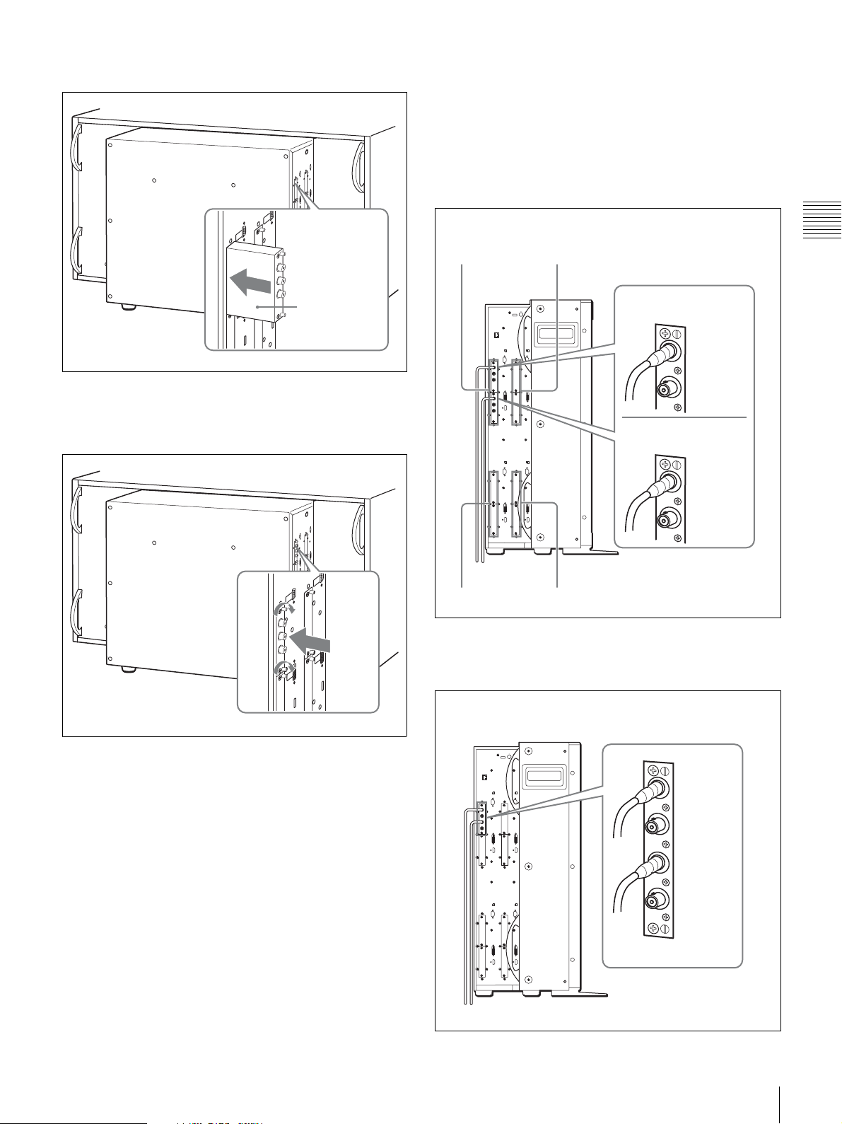
2
Insert the adaptor facing the board as shown below.
To connect the input cables
When the BKM-243HS or BKM-244CC input
adaptors are used
Input the Link A signal to option slot 1, and Link B signal
to option slot 2.
Connect the cables to the connectors with the same input
number on the input adaptors installed in option slots 1 and
2.
Board
3
Push the adaptor in until it is firmly fit into the
connector inside the monitor, then tighten the two
screws to secure the adaptor.
Example when Dual-link input cables are connected
A
A
C
B
Option slot 1
Link A
INPUT 1
INPUT 2
Option slot 2
Link B
INPUT 1
INPUT 2
D
Chapter 2 Preparations
Installation of the input adaptor for Duallink connection
Two BKM-243HS or BKM-244CC input adaptors or one
BKM-250TG input adaptor is required for each input
block A to D. When the BKM-243HS or BKM-244CC
adaptors are used, install them in option slots 1 and 2. The
input adaptors of different models cannot be used at the
sama time.
When the BKM-250TG input adaptor is used
Input the Link A signal to INPUT 1, and Link B signal to
INPUT 2.
Example when Dual-link input cables are connected
INPUT 1
INPUT 2
Installing an Input Adaptor
19
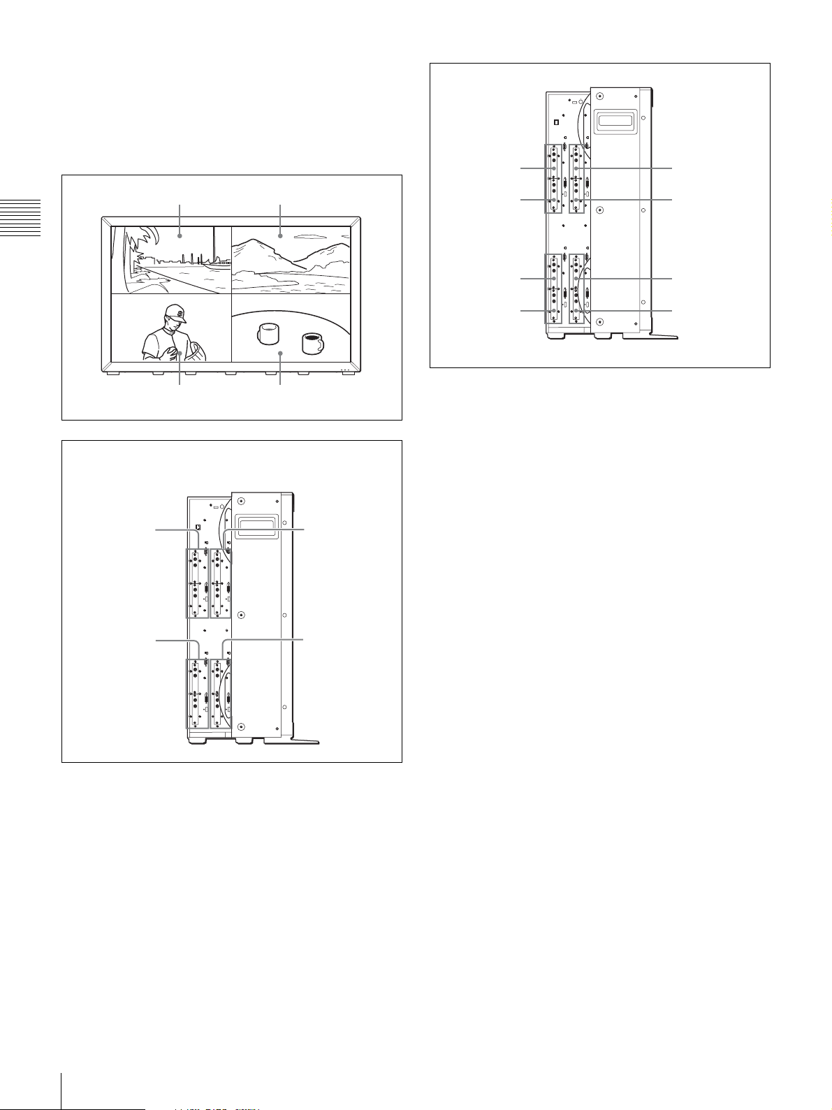
Four divided screens and the displayed
positions of input signals
The monitor can display different input signals on four
divided screens. The positions of input signals (DVI-D/
HDMI input connectors and the positions where the input
adaptors are installed) for each screen are defined.
Slot 1
Slot 1
Screen A Screen B
Chapter 2 Preparations
Screen C Screen D
DVI-D or HDMI input connectors and the position where the
DVI-D or HDMI input connectors and the position where the
input adaptors are to be installed for each screen
input adaptors are to be installed for each screen
For screen A
(Input block A)
Slot 1
Slot 1
For screen B
For screen B
(Input block B)
(Input block B)
Slot 1
Slot 2
Slot 1
Slot 2
Slot 2
Slot 1
Slot 2
For screen C
(Input block C)
Slot 2
Slot 2
Slot 1
Slot 2
Slot 2
For screen D
(Input block D)
Slot 1
Slot 2
Combination of input adaptors and
positions of input slots
Install input adaptors of the same model in the same option
slot (slot 1 or slot 2) for each screen.
You can install the four input adaptors in slot 1 only or
eight input adaptors in slot 1 and slot 2.
To install the adaptors in slot 1 only
Install the input adaptors of the same model in slot 1 for
four screens.
To install the eight adaptors
The four input adaptors to be installed in slot 1 and those
in slot 2 should be of the same models, respectively.
20
Installing an Input Adaptor
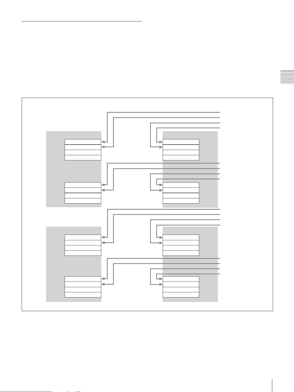
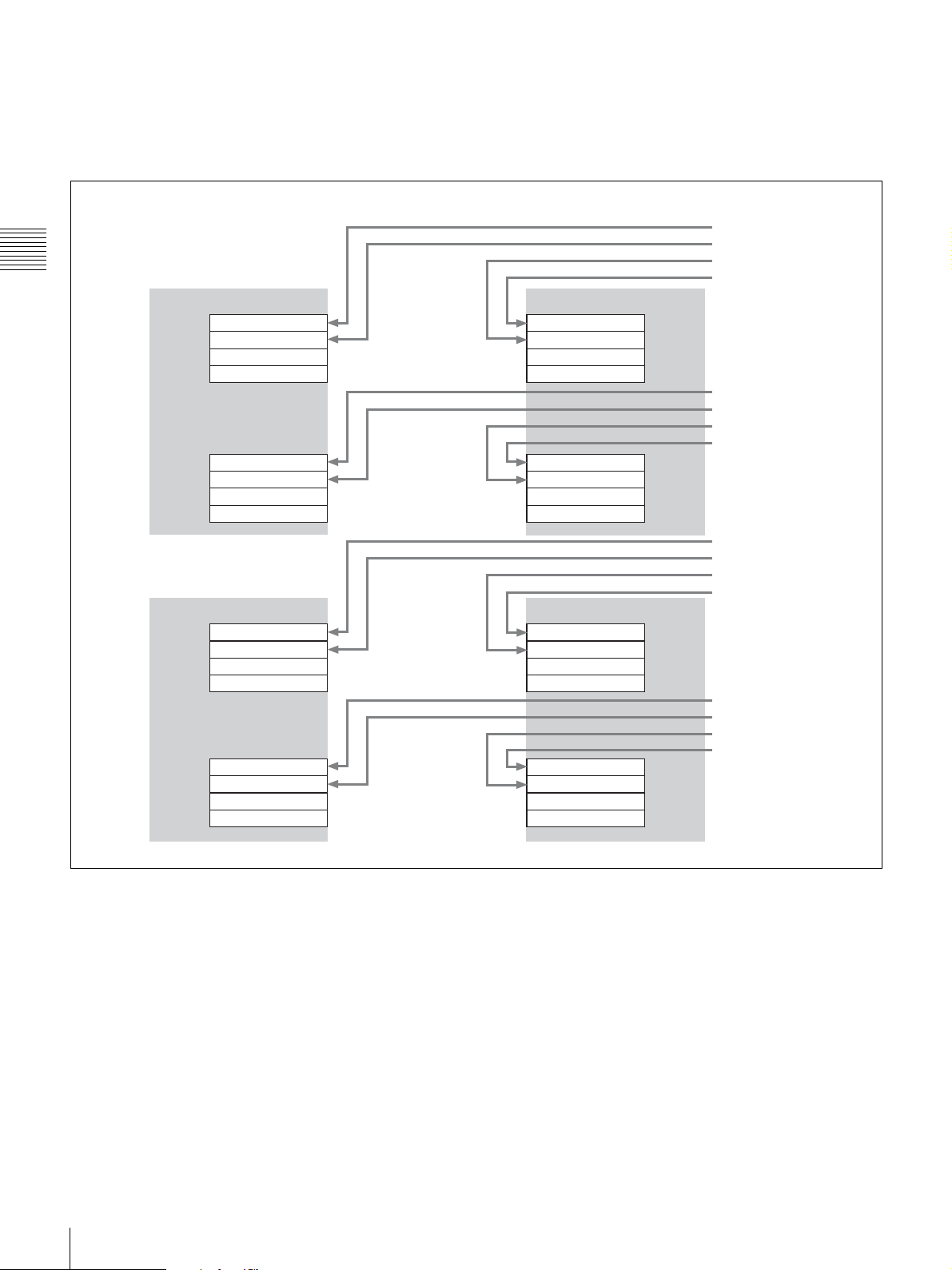
Connecting the Cable
Connections when the monitor is used in
4K/QFHD mode
To input from the DVI-D or HDMI input connectors
A 4K/QFHD resolution signal is divided into four and the
divided signals are connected to the DVI-D or HDMI input
connectors on input blocks A to D.
Example when eight input adaptors are used
A B
OPTION 1 OPTION 1
INPUT 1
INPUT 2
MONITOR OUT
INPUT 1
INPUT 2
MONITOR OUT
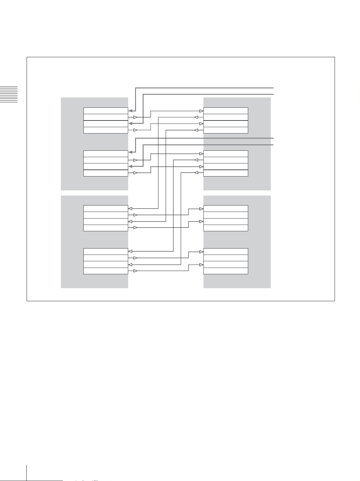
To input from the connectors on the input adaptors
A 4K/QFHD resolution signal is divided into four and the
divided signals are connected to the input adaptors
installed in input blocks A to D. For every screen install the
input adaptor in the same slot (slot 1 or slot 2) and connect
the signal to the same input (INPUT 1 or INPUT 2) on the
adaptor.
When the BKM-243HS or BKM-244CC is used
To connect in Single-link
When four input adaptors are installed, you can select the
signal from two systems and when eight input adaptors are
installed, you can select from four systems.
Input signal 1
Input signal 2
Input signal 2
Input signal 1
INPUT 1
INPUT 2
MONITOR OUT
Input signal 3
Input signal 4
Input signal 4
Input signal 3
INPUT 1
INPUT 2
MONITOR OUT
OPTION 2OPTION 2
Chapter 2 Preparations
C D
OPTION 1 OPTION 1
INPUT 1
INPUT 2
MONITOR OUT
INPUT 1
INPUT 2
MONITOR OUT
INPUT 1
INPUT 2
MONITOR OUT
INPUT 1
INPUT 2
MONITOR OUT
OPTION 2OPTION 2
Input signal 1
Input signal 2
Input signal 2
Input signal 1
Input signal 3
Input signal 4
Input signal 4
Input signal 3
Installing an Input Adaptor
21
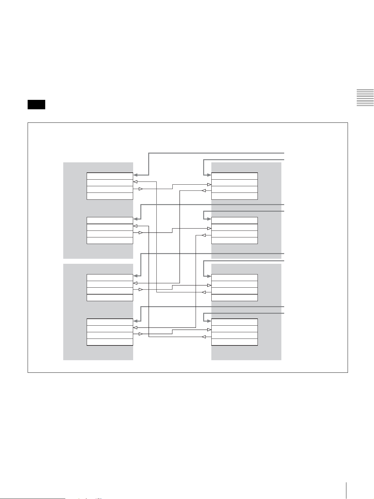
Connections when the monitor is used in
Quad View mode
Connect the signals to the DVI-D or HDMI input
connectors or the connectors on the input adaptors in input
blocks A, B, C and D.
Example when eight input adaptors are used
Chapter 2 Preparations
A B
OPTION 1 OPTION 1
INPUT 1
INPUT 2
MONITOR OUT
INPUT 1
INPUT 2
MONITOR OUT
When the BKM-243HS or BKM-244CC is used
To connect in Single-link
When four input adaptors are installed, you can select the
signal from eight systems and when eight input adaptors
are installed, you can select from 16 systems.
Input signal 1
Input signal 5
Input signal 6
Input signal 2
INPUT 1
INPUT 2
MONITOR OUT
Input signal 9
Input signal 13
Input signal 14
Input signal 10
INPUT 1
INPUT 2
MONITOR OUT
OPTION 2OPTION 2
C D
OPTION 1 OPTION 1
INPUT 1
INPUT 2
MONITOR OUT
INPUT 1
INPUT 2
MONITOR OUT
INPUT 1
INPUT 2
MONITOR OUT
INPUT 1
INPUT 2
MONITOR OUT
OPTION 2OPTION 2
Input signal 3
Input signal 7
Input signal 8
Input signal 4
Input signal 11
Input signal 15
Input signal 16
Input signal 12
22
Installing an Input Adaptor
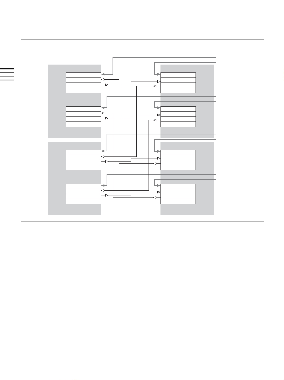
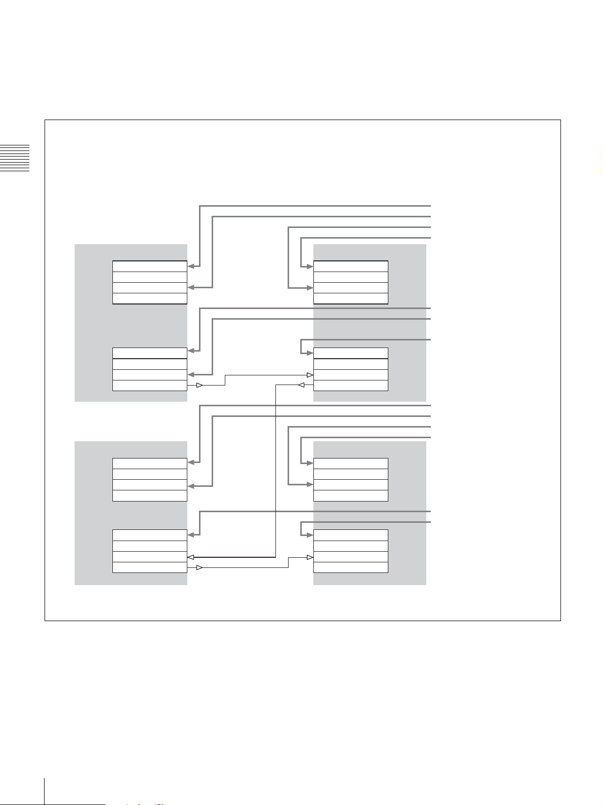
Connections when the monitor is used by
switching between Quad View and 2K/HD
Zoom modes
To input the signals in 2K/HD Zoom mode, the monitor
output connectors on the input adaptors are used;
therefore, coaxial cables for connections among the input
adaptors are required, as well as those for connection
between the signal source and the monitor.
Note
Use a coaxial cable less than 1 m (3.3 feet) long.
Example when eight input adaptors are used
A B
OPTION 1 OPTION 1
INPUT 1
INPUT 2
MONITOR OUT
INPUT 1
INPUT 2
MONITOR OUT
When the BKM-243HS or BKM-244CC is used
Input the signal to INPUT 1 on the input adaptor installed
in input blocks A to D, and input the same signal to be
output from MONITOR OUT to INPUT 2 on the input
adaptor installed in the same slot (slot 1 or slot 2) of
another input block.
To connect in Single-link
When four input adaptors are installed, you can select the
signal from four systems and when eight input adaptors are
installed, you can select from eight systems.
Input signal 1
Input signal 2
INPUT 1
INPUT 2
MONITOR OUT
Input signal 5
Input signal 6
INPUT 1
INPUT 2
MONITOR OUT
OPTION 2OPTION 2
Chapter 2 Preparations
C D
OPTION 1 OPTION 1
INPUT 1
INPUT 2
MONITOR OUT
INPUT 1
INPUT 2
MONITOR OUT
INPUT 1
INPUT 2
MONITOR OUT
INPUT 1
INPUT 2
MONITOR OUT
OPTION 2OPTION 2
Input signal 3
Input signal 4
Input signal 7
Input signal 8
Installing an Input Adaptor
23
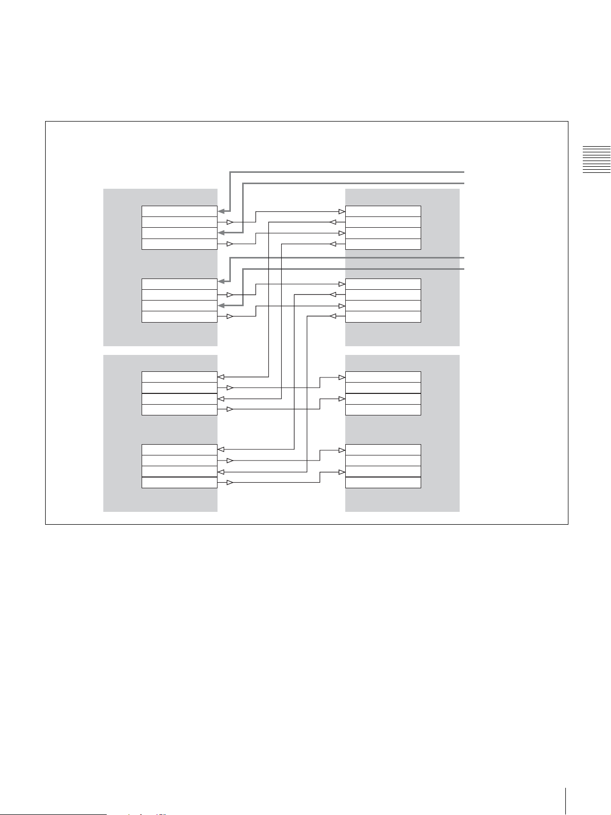
To connect in Dual-link
When eight input adaptors are installed, you can select
from four systems.
Example when eight input adaptors are used
A B
OPTION 1 OPTION 1
Chapter 2 Preparations
C D
OPTION 1 OPTION 1
INPUT 1
INPUT 2
MONITOR OUT
INPUT 1
INPUT 2
MONITOR OUT
INPUT 1
INPUT 2
MONITOR OUT
INPUT 1
INPUT 2
MONITOR OUT
INPUT 1
INPUT 2
MONITOR OUT
INPUT 1
INPUT 2
MONITOR OUT
Input signal 1 Link A
Input signal 2 Link A
Input signal 1 Link B
Input signal 2 Link B
OPTION 2OPTION 2
Input signal 3 Link A
Input signal 4 Link A
INPUT 1
INPUT 2
MONITOR OUT
INPUT 1
INPUT 2
MONITOR OUT
Input signal 3 Link B
Input signal 4 Link B
OPTION 2OPTION 2
24
Installing an Input Adaptor
When the BKM-250TG is used
Input the signal to INPUT 1 or INPUT 2 on the input
adaptor installed in input block A, and input the same
signal to be output from MONITOR OUT 1 or MONITOR
OUT 2 to the same INPUT (INPUT 1 or INPUT 2) on the
Example when eight input adaptors are used
input adaptor installed in the same slot (slot 1 or slot 2) of
input block B, C or D.
To connect in Single-link
When four input adaptors are installed, you can select the
signal from two systems and when eight input adaptors are
installed, you can select from four systems.
A B
OPTION 1 OPTION 1
INPUT 1
MONITOR OUT 1
INPUT 2
MONITOR OUT 2
INPUT 1
MONITOR OUT 1
INPUT 2
MONITOR OUT 2
INPUT 1
MONITOR OUT 1
INPUT 2
MONITOR OUT 2
INPUT 1
MONITOR OUT 1
INPUT 2
MONITOR OUT 2
OPTION 2OPTION 2
C D
OPTION 1 OPTION 1
INPUT 1
MONITOR OUT 1
INPUT 2
MONITOR OUT 2
INPUT 1
MONITOR OUT 1
INPUT 2
MONITOR OUT 2
INPUT 1
MONITOR OUT 1
INPUT 2
MONITOR OUT 2
INPUT 1
MONITOR OUT 1
INPUT 2
MONITOR OUT 2
OPTION 2OPTION 2
Input signal 1
Input signal 2
Input signal 3
Input signal 4
Chapter 2 Preparations
Installing an Input Adaptor
25
To connect in Dual-link
When four input adaptors are installed, you can select the
signal from one system and when eight input adaptors are
installed, you can select the signal from two systems.
Example when eight input adaptors are used
Chapter 2 Preparations
A B
OPTION 1 OPTION 1
INPUT 1
MONITOR OUT 1
INPUT 2
MONITOR OUT 2
INPUT 1
MONITOR OUT 1
INPUT 2
MONITOR OUT 2
C D
OPTION 1 OPTION 1
INPUT 1
MONITOR OUT 1
INPUT 2
MONITOR OUT 2
INPUT 1
MONITOR OUT 1
INPUT 2
MONITOR OUT 2
INPUT 1
MONITOR OUT 1
INPUT 2
MONITOR OUT 2
INPUT 1
MONITOR OUT 1
INPUT 2
MONITOR OUT 2
Input signal 1 Link A
Input signal 1 Link B
Input signal 2 Link A
Input signal 2 Link B
OPTION 2OPTION 2
INPUT 1
MONITOR OUT 1
INPUT 2
MONITOR OUT 2
Note on displaying the picture in 2K/HD Zoom
mode
A 2K/HD Zoom mode cannot be selected when a DVI-D
or HDMI signal is input.
The mode is available when four or eight input adaptors
are installed and an HD-SDI (Single-link or Dual-link) or
3G-SDI signal is input.
INPUT 1
MONITOR OUT 1
INPUT 2
MONITOR OUT 2
OPTION 2OPTION 2
26
Installing an Input Adaptor

Connections when the monitor is used in
4K/QFHD or Quad View mode
When the BKM-243HS or BKM-244CC is used
When eight input adaptors are installed, you can select
Dual-link 4K signals (4K/QFHD mode) from one system
or an HD-SDI signal (Quad View mode) from eight
systems.
Example when eight input adaptors are used
• The INPUT 1 connectors on OPTION 1 and OPTION 2 are used for Dual-link connection in 4K/QFHD mode.
• The INPUT 2 connectors on OPTION 1 and OPTION 2 are used for Single-link connection in Quad View mode.
A B
OPTION 1 OPTION 1
INPUT 1
INPUT 2
MONITOR OUT
INPUT 1
INPUT 2
MONITOR OUT
INPUT 1
INPUT 2
MONITOR OUT
INPUT 1
INPUT 2
MONITOR OUT
OPTION 2OPTION 2
Chapter 2 Preparations
Input signal 1 Link A
Input signal 2 HD-SDI
Input signal 3 HD-SDI
Input signal 1 Link A
Input signal 1 Link B
Input signal 6 HD-SDI
Input signal 7 HD-SDI
Input signal 1 Link B
C D
OPTION 1 OPTION 1
INPUT 1
INPUT 2
MONITOR OUT
INPUT 1
INPUT 2
MONITOR OUT
INPUT 1
INPUT 2
MONITOR OUT
INPUT 1
INPUT 2
MONITOR OUT
OPTION 2OPTION 2
Input signal 1 Link A
Input signal 4 HD-SDI
Input signal 5 HD-SDI
Input signal 1 Link A
Input signal 1 Link B
Input signal 8 HD-SDI
Input signal 9 HD-SDI
Input signal 1 Link B
Installing an Input Adaptor
27
When the BKM-250TG is used
When eight input adaptors are installed, you can select
Dual-link 4K signals (4K/QFHD mode) from one system
or a Single-link HD signal (Quad View mode) from four
systems and a Single-link HD signal (2K/HD Zoom mode)
from one system.
Example when eight input adaptors are used
• The INPUT 1 and INPUT 2 connectors on OPTION 1 are used for Dual-link connection in 4K/QFHD mode.
• The INPUT 1 connectors on OPTION 2 are used for Single-link connection in Quad View mode.
Chapter 2 Preparations
• The INPUT 2 connectors on OPTION 2 are used for Single-link connection in 2K/HD Zoom mode.
A B
OPTION 1 OPTION 1
INPUT 1
MONITOR OUT 1
INPUT 2
MONITOR OUT 2
INPUT 1
MONITOR OUT 1
INPUT 2
MONITOR OUT 2
C D
OPTION 1 OPTION 1
INPUT 1
MONITOR OUT 1
INPUT 2
MONITOR OUT 2
INPUT 1
MONITOR OUT 1
INPUT 2
MONITOR OUT 2
INPUT 1
MONITOR OUT 1
INPUT 2
MONITOR OUT 2
INPUT 1
MONITOR OUT 1
INPUT 2
MONITOR OUT 2
INPUT 1
MONITOR OUT 1
INPUT 2
MONITOR OUT 2
INPUT 1
MONITOR OUT 1
INPUT 2
MONITOR OUT 2
Input signal 1 Link A
Input signal 1 Link B
Input signal 1 Link B
Input signal 1 Link A
Input signal 2 HD-SDI
Input signal 6 HD-SDI
(2K/HD Zoom mode)
Input signal 3 HD-SDI
OPTION 2OPTION 2
Input signal 1 Link A
Input signal 1 Link B
Input signal 1 Link B
Input signal 1 Link A
Input signal 4 HD-SDI
Input signal 5 HD-SDI
OPTION 2OPTION 2
28
Installing an Input Adaptor
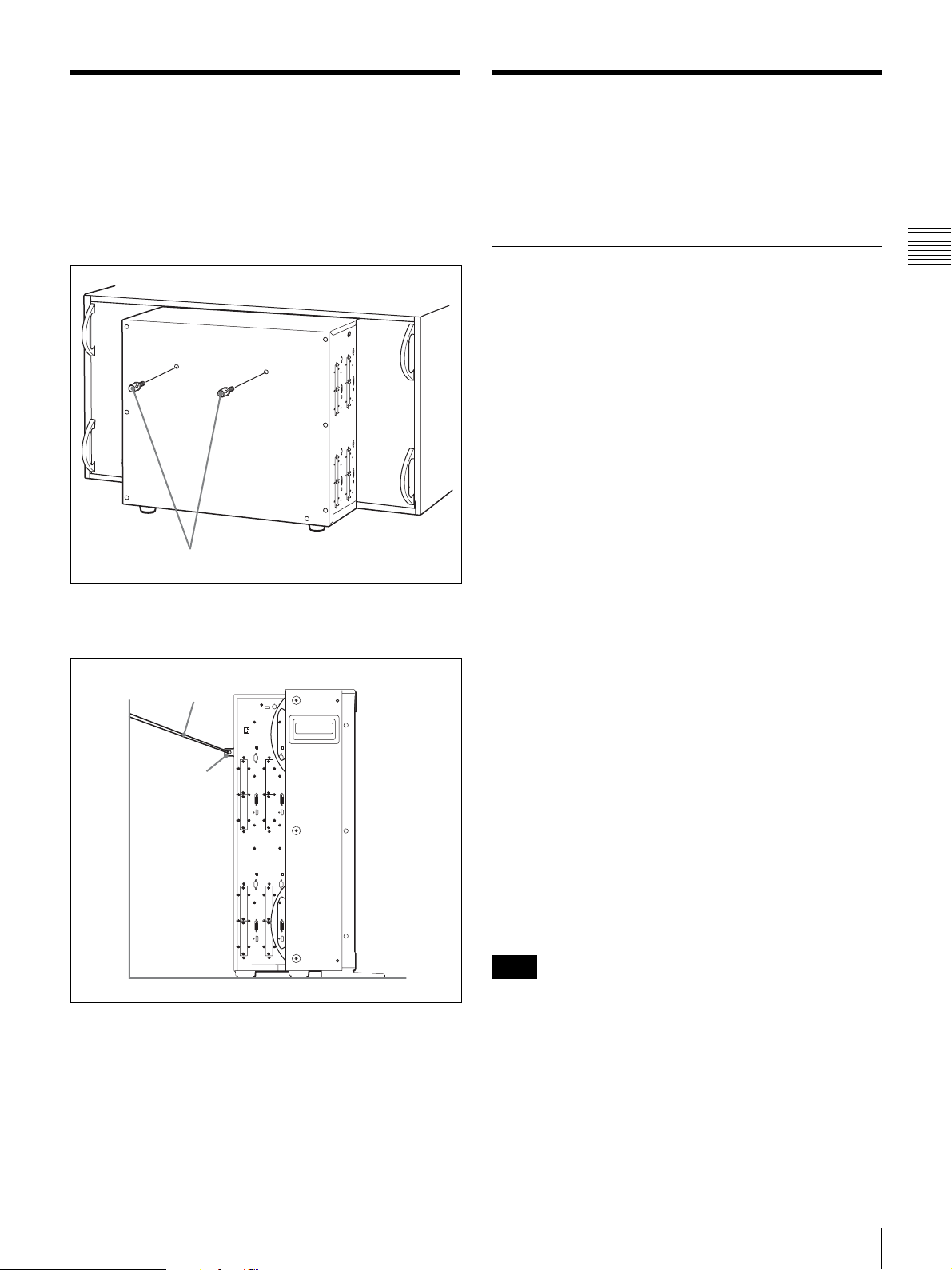
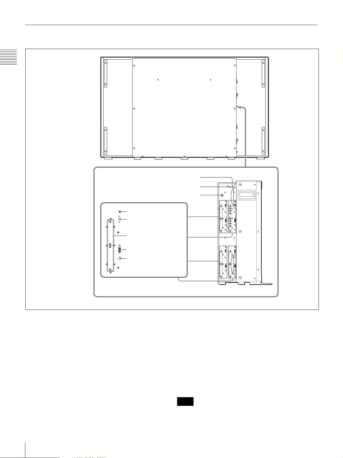
Attaching the Hooks
You can prevent the monitor from falling by using the
supplied hook.
1
Attach two hooks to the upper position on the rear
panel.
Installing Application Software (PC Application)
Install the SRM Manager contained on the supplied CDROM in your PC for controlling the monitor from the PC.
Hooks (supplied)
2
Pass a piece of string, etc., through the hooks and
secure them to the floor or wall.
String, etc.
Hooks
Required
• LAN cable (straight, 10BASE-T/100BASE-TX)
• PC (for controlling the monitor)
Recommended System Requirements
The following are recommended to operate the SRM
Manager.
•OS
Windows XP SP3
Professional Edition
Windows Vista SP1
Ultimate Edition
Business Edition
Windows 7
Ultimate Edition
Professional Edition
•PC
CPU: Intel Celeron 1 GHz or more
Memory: 512 MB or more (Windows XP), 1 GB or more
(Windows Vista, Windows 7)
Display: 1024 × 768 or higher (Hi Color 16 bit or higher)
HDD: Connected to a PC via the IDE port, Usable
memory with 700 MB or more
OP drive: CD-ROM ×8 or faster
•Browser
Internet Explorer 6.0 or later
•Network
10BASE-T/100BASE-TX
• Connectable in the internet
• .NET Framework 3.5 SP1
Chapter 2 Preparations
Note
The SRM Manager will not work on some computers and
OS even though they satisfy the above requirements.
Some names of the items in this manual are shortened as follows:
Microsoft Windows XP Professional is mentioned as Windows XP.
Microsoft Windows Vista Ultimate and Microsoft Windows Vista Business
are mentioned as Windows Vista.
Microsoft Windows 7 Ultimate and Microsoft Windows 7 Professional are
mentioned as Windows 7.
Attaching the Hooks / Installing Application Software (PC Application)
29
Installing the SRM Manager
To control the SRM-L560 monitor with the SRM
Manager, you are required to download .NET Framework
3.5 Service Pack 1 via Windows Update and install it in
your computer.
Microsoft Corporation.
Note
Sony will not be liable for any cost arising from
Chapter 2 Preparations
downloading or installing and any damage in connection
with above-mentioned software application.
1) .NET Framework 3.5 has been installed on Windows 7.
1)
For details, access a web site of
To install the SRM Manager
1
Insert the supplied CD-ROM into the CD-ROM drive
of a PC.
The index window of the browser starts automatically.
2
Click “Install SRM Manager” in the index window.
The setup.exe starts.
If setup.exe does not start automatically, double-click
setup.exe in the root folder to start it manually.
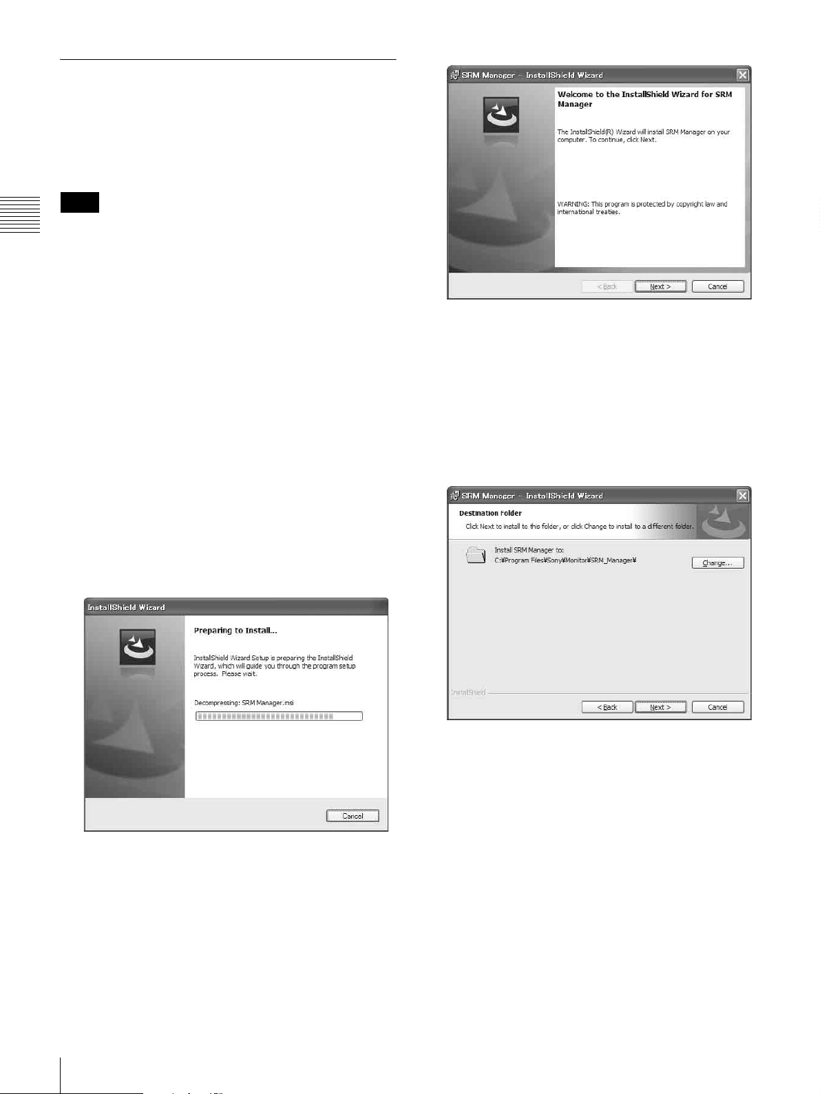
3
Follow the instructions in the window and click
Execute.
The window for preparing the installation appears.
4
Click Next.
The License Agreement window appears.
5
Read the license agreement, click “I accept the terms
in the license agreement” if you agree to be bound by
the terms, and click Next.
The select window of the destination folder in which
to install the SRM Manager appears.
After a while, the wizard of the SRM Manager
appears.
30
Installing Application Software (PC Application)
When you want to install it in the default folder, click
Next.
We recommend to install it in the default folder.
If you wish to install it in a different folder, click
Change…, specify the folder, click OK, then click
Next.
The program installation starts.
After a while, the following window appears.
 Loading...