

Sony SRMASTER SR-R4 Operation Manual

SR-R4
(SY)
4-412-781-01 (1)
Sony Corporation
Printed on recycled paper.
Printed in Japan
2011.11 32
© 2011
PORTABLE MEMORY RECORDER
SR-R4
CONTROL PANEL
SRK-CP1
OPERATION MANUAL [English]
1st Edition
Before operating the unit, please read this
manual thoroughly and retain it for future
reference.
WARNING
To reduce the risk of fire or
electric shock, do not
expose this apparatus to
rain or moisture.
To avoid electrical shock,
do not open the cabinet.
Refer servicing to qualified
personnel only.
Do not install the appliance in a confined
space, such as book case or built-in cabinet.
IMPORTANT
The nameplate is located on the bottom of
the left side.
WARNING
Excessive sound pressure from earphones
and headphones can cause hearing loss.
In order to use this product safely, avoid
prolonged listening at excessive sound
pressure levels.
Caution
Use of controls or adjustments or
performance of procedures other than those
specified herein may result in hazardous
radiation exposure.
This HD Portable Memory Recorder is
classified as a CLASS 1 LASER PRODUCT.
Laser Diode Properties
Wavelength: 850 nm
Emission duration: Pulse modulation
Laser output power: 4 mW/channel (max)
Standard: IEC60825-1 (2007)
Egenskaber for laserdiode
Bølgelængde: 850 nm
Strålingsvarighed: Pulsmodulering
Afgivet lasereffekt: 4 mW/kanal (maks.)
Standard: IEC60825-1 (2007)
Laserdiod - Egenskaper
Våglängd: 850 nm
Strålningens varaktighet: Pulsmodulation
Lasereffekt: 4 mW/kanal (max)
Standard: IEC60825-1 (2007)
Egenskaper for laserdiode
Bølgelengde: 850 nm
Strålingsvarighet: Pulsmodulasjon
Utgangseffekt for laser: 4 mW / kanal (maks.)
Standard: IEC60825-1 (2007)
VAROITUS!
LAITTEEN KÄYTTÄMINEN MUULLA KUIN
TÄSSÄ KÄYTTÖOHJEESSA MAINITULLA
TAVALLA SAATTAA ALTISTAA
KÄYTTÄJÄN TURVALLISUUSLUOKAN 1
YLITTÄVÄLLE NÄKYMÄTTÖMÄLLE
LASERSÄTEILYLLE.
VARNING
OM APPARATEN ANVÄNDS PÅ ANNAT
SÄTT ÄN I DENNA BRUKSANVISNING
SPECIFICERATS, KAN ANVÄNDAREN
UTSÄTTAS FÖR OSYNLIG
LASERSTRÅLNING, SOM ÖVERSKRIDER
GRÄNSEN FÖR LASERKLASS 1.
Caution
The use of optical instruments with this
product will increase eye hazard.
2

For the customers in the U.S.A.
This equipment has been tested and found
to comply with the limits for a Class A digital
device, pursuant to Part 15 of the FCC
Rules. These limits are designed to provide
reasonable protection against harmful
interference when the equipment is operated
in a commercial environment. This
equipment generates, uses, and can radiate
radio frequency energy and, if not installed
and used in accordance with the instruction
manual, may cause harmful interference to
radio communications. Operation of this
equipment in a residential area is likely to
cause harmful interference in which case the
user will be required to correct the
interference at his own expense.
You are cautioned that any changes or
modifications not expressly approved in this
manual could void your authority to operate
this equipment.
All interface cables used to connect
peripherals must be shielded in order to
comply with the limits for a digital device
pursuant to Subpart B of Part 15 of FCC
Rules.
This device complies with Part 15 of the FCC
Rules. Operation is subject to the following
two conditions: (1) this device may not cause
harmful interference, and (2) this device
must accept any interference received,
including interference that may cause
undesired operation.
For the customers in Canada
This Class A digital apparatus complies with
Canadian ICES-003.
For the customers in Europe
This product with the CE marking complies
with the EMC Directive issued by the
Commission of the European Community.
Compliance with this directive implies
conformity to the following European
standards:
• EN55103-1 : Electromagnetic
Interference (Emission)
• EN55103-2 : Electromagnetic
Susceptibility (Immunity)
This product is intended for use in the
following Electromagnetic Environments: E1
(residential), E2 (commercial and light
industrial), E3 (urban outdoors), E4
(controlled EMC environment, ex. TV
studio).
For the customers in Europe
The manufacturer of this product is Sony
Corporation, 1-7-1 Konan, Minato-ku,
Tokyo, Japan.
The Authorized Representative for EMC and
product safety is Sony Deutschland GmbH,
Hedelfinger Strasse 61, 70327 Stuttgart,
Germany. For any service or guarantee
matters please refer to the addresses given
in separate service or guarantee documents.
For the State of California, USA only
Perchlorate Material - special handling may
apply, See
www.dtsc.ca.gov/hazardouswaste/
perchlorate
Perchlorate Material : Lithium battery
contains perchlorate.
For the customers in Taiwan only
3
Avant d’utiliser l’appareil, veuillez lire
attentivement ce manuel et le conserver
pour future référence.
AVERTISSEMENT
Afin de réduire les risques
d’incendie ou
d’électrocution, ne pas
exposer cet appareil à la
pluie ou à l’humidité.
Afin d’écarter tout risque
d’électrocution, garder le
coffret fermé. Ne confier
l’entretien de l’appareil
qu’à un personnel qualifié.
Ne pas installer l’appareil dans un endroit
confiné, par exemple une bibliothèque ou un
placard encastré.
IMPORTANT
La plaque signalétique se situe sous le
panneau de gauche.
AVERTISSEMENT
Une pression acoustique excessive en
provenance des écouteurs ou du casque
peut provoquer une baisse de l’acuité
auditive.
Pour utiliser ce produit en toute sécurité,
évitez l’écoute prolongée à des pressions
sonores excessives.
Enregistreur mémoire portable HD est
classée comme PRODUIT LASER DE
CLASSE 1.
Pour les clients au Canada
Cet appareil numérique de la classe A est
conforme à la norme NMB-003 du Canada.
Pour les clients en Europe
Ce produit portant la marque CE est
conforme à la Directive sur la compatibilité
électromagnétique (EMC) émise par la
Commission de la Communauté
européenne.
La conformité à cette directive implique la
conformité aux normes européennes
suivantes :
• EN55103-1 : Interférences
électromagnétiques (émission)
• EN55103-2 : Sensibilité
électromagnétique (immunité)
Ce produit est prévu pour être utilisé dans
les environnements électromagnétiques
suivants : E1 (résidentiel), E2 (commercial et
industrie légère), E3 (urbain extérieur) et E4
(environnement EMC contrôlé, ex. studio de
télévision).
Pour les clients en Europe
Le fabricant de ce produit est Sony
Corporation, 1-7-1 Konan, Minato-ku,
Tokyo, Japon.
Le représentant autorisé pour EMC et la
sécurité des produits est Sony Deutschland
GmbH, Hedelfinger Strasse 61, 70327
Stuttgart, Allemagne. Pour toute question
concernant le service ou la garantie, veuillez
consulter les adresses indiquées dans les
documents de service ou de garantie
séparés.
4
Bitte lesen Sie dieses Handbuch vor der
Benutzung des Geräts sorgfältig durch und
bewahren Sie es zum späteren
Nachschlagen auf.
WARNUNG
Um die Gefahr von Bränden
oder elektrischen Schlägen
zu verringern, darf dieses
Gerät nicht Regen oder
Feuchtigkeit ausgesetzt
werden.
Um einen elektrischen
Schlag zu vermeiden, darf
das Gehäuse nicht geöffnet
werden. Überlassen Sie
Wartungsarbeiten stets nur
qualifiziertem
Fachpersonal.
Das Gerät nicht an Orten aufstellen, z.B. in
Bücherregalen oder Einbauschränken, wo
keine ausreichende Belüftung gewährleistet
ist.
WICHTIG
Das Namensschild befindet sich auf der
Unterseite der linken Wand.
WARNUNG
Zu hoher Schalldruck von Ohrhörern und
Kopfhörern kann Gehörschäden
verursachen.
Um dieses Produkt sicher zu verwenden,
vermeiden Sie längeres Hören bei sehr
hohen Schalldruckpegeln.
Dieser Tragbarer HD-Speicherrecorder ist
als LASERPRODUKT DER KLASSE 1
eingestuft.
Daten der Laserdiode
Wellenlänge: 850 nm
Emissionsdauer: Pulsmodulation
Laser-Ausgangsleistung: 4 mW/Kanal (max.)
Standard: IEC60825-1 (2007)
Für Kunden in Europa
Dieses Produkt besitzt die CEKennzeichnung und erfüllt die EMVRichtlinie der EG-Kommission.
Angewandte Normen:
• EN55103-1: Elektromagnetische
Verträglichkeit (Störaussendung)
• EN55103-2: Elektromagnetische
Verträglichkeit (Störfestigkeit)
Für die folgenden elektromagnetischen
Umgebungen: E1 (Wohnbereich), E2
(kommerzieller und in beschränktem Maße
industrieller Bereich), E3 (Stadtbereich im
Freien) und E4 (kontrollierter EMV-Bereich,
z.B. Fernsehstudio).
5

Für Kunden in Europa
Der Hersteller dieses Produkts ist Sony
Corporation, 1-7-1 Konan, Minato-ku,
Tokyo, Japan.
Der autorisierte Repräsentant für EMV und
Produktsicherheit ist Sony Deutschland
GmbH, Hedelfinger Strasse 61, 70327
Stuttgart, Deutschland. Bei jeglichen
Angelegenheiten in Bezug auf Kundendienst
oder Garantie wenden Sie sich bitte an die in
den separaten Kundendienst- oder
Garantiedokumenten aufgeführten
Anschriften.
6

Table of Contents
Table of Contents
Chapter 1 : Overview
Features................................................... 9
System Configuration Example............ 9
Names of Parts...................................... 10
Overall View ............................. 10
Left Side View........................... 10
Rear and Right Side View......... 11
Control Panel
(SRK-CP1, Option)............. 12
Display...................................... 13
Chapter 2 : Preparation
Work Flow ............................................ 15
Mount Control Panel on Unit ............. 15
Connect F65.......................................... 17
Mount Control Panel on the F65........ 19
Attach the Battery Pack ...................... 20
Turn Power On .................................... 21
Insert SRMemory Card ..................... 22
Formatting an SRMemory Card
(File System Format) .......... 23
Chapter 3 : Basic Menu Operations
Buttons Used for Menu
Operations........................... 25
Serve for Selecting a Menu ....... 25
Locking the Controls................. 26
Signal Format Settings ........................ 27
Selecting the Signal Format ...... 27
Operation Mode Settings..................... 28
Display Settings.................................... 28
Using the Backlight................... 28
Using the Screen Saver.............. 28
Date Settings ......................................... 29
Chapter 4 : Recording and Playback
Recording Preparations and
Operations ...................................... 30
Setting the Audio Signals .......... 30
Setting the Recording Levels..... 31
Setting the Time Code and User
Bits ..................................... 32
To set the operation mode ......... 34
Recording .................................. 34
Playback Preparations and
Operations ...................................... 35
Making Settings Related to Audio
Monitor Signals................... 35
Adjusting Playback Audio
Levels ................................. 35
Selecting the Time Data to Display
During Playback.................. 35
To set the operation mode ......... 36
Playback .................................... 36
How to Use the Recording and Playback
Operation Buttons.......................... 37
FILE LIST Operations........................ 38
Displaying a File List ................ 38
Performing File Operations....... 39
Changing the File Display
Order ................................... 39
Chapter 5 : Menu Details
TC Setup Menu .................................... 40
VIDEO Setup Menu............................. 42
AUDIO Setup Menu............................. 43
SYSTEM Setup Menu ......................... 45
Table of Contents
7

Appendix
Maintenance and Inspections.............. 48
Note About the CAMERA
Connector............................ 48
Cleaning the CAMERA
Connector............................ 48
Specifications........................................ 50
General ...................................... 50
Video ......................................... 50
Audio......................................... 50
Input/Output Connectors ........... 50
Supplied Accessories................. 51
Optional Accessories................. 51
Error Messages and Warning
Messages ......................................... 52
About Error Messages............... 52
About Warning Messages ......... 52
Warning System................................... 53
Troubleshooting ................................... 54
About Recording/Playback Formats .. 57
Index...................................................... 58
Table of Contents
8
Chapter 1 Overview
Features System Configuration
Example
Chapter 1 Overview
The SR-R4 is a portable memory recorder of the
SRMASTER series, featuring an F65 dockable
CAMERA port and using the newly developed
SRMemory card for the recording media.
SRMASTER and SRMemory are trademarks of
Sony Corporation.
F65RAW Recording
Supports F65RAW recording.
There is 16-channel (uncompressed, 24-bit,
48 kHz) support for audio.
F65 dockable operation
Supports dockable operation in combination with
the F65.
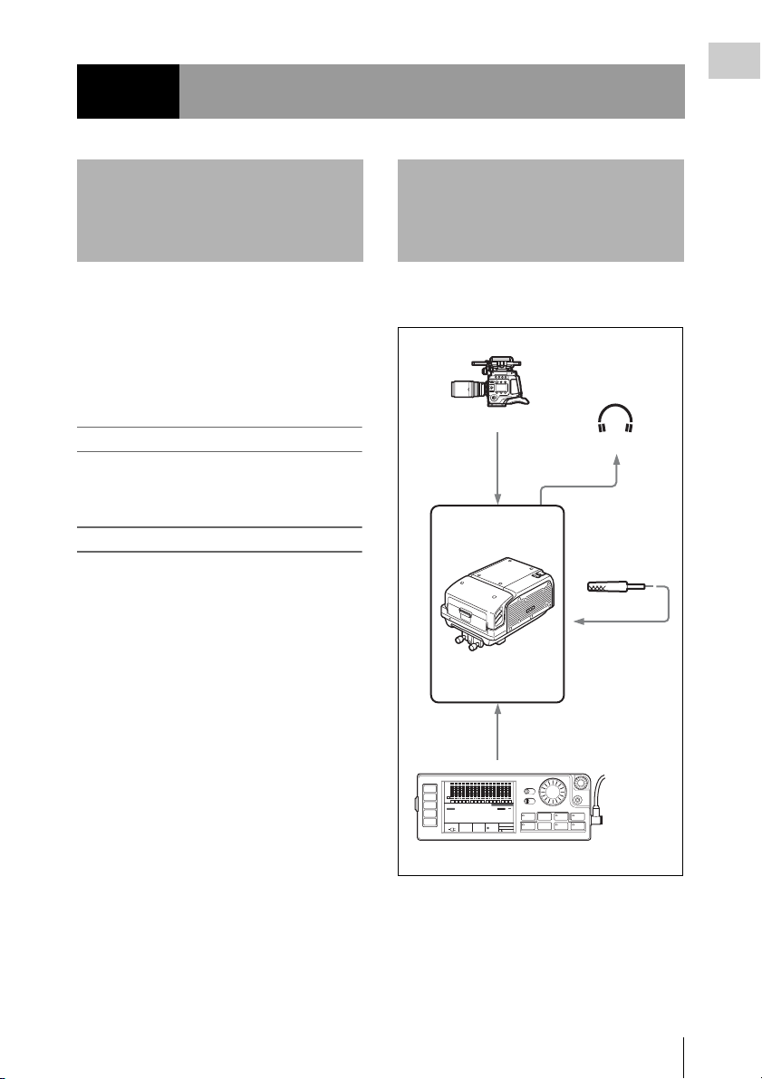
The following figure shows a system configured
around the SR-R4.
F65
HD color video camera
Earphones/Headphones
Audio input
Microphone
Analog: 2 channels
SR-R4
CTRL PANEL
SDI
SDI
SDI
SDI
SDI
SDI
SDI
SDI
SDI
SDI
SDI
SDI
SDI
SDI
SDI
dB
0
-10
HOME
-20
-30
-60
EMP
TC
EE
LR
1
VIDEO
TCG
AUDIO
00H 00M00S 00F
SYSTEM
16.5V
Control Panel (SRK-CP1, option)
SDI
KEY INHI
EMP
EMP
EMP
LR
LR
LR
2
3
4
STOP
REMAIN
10min
OFF ON
EMP
EMP
EMP
EMP
EMP
EMP
EMP
EMP
EMP
EMP
EMP
EMP
LR
LR
LR
LR
LR
LR
LR
LR
LR
LR
LR
LR
OFF ON
5
6
7
8
9
10
11
12
13
14
15
16
SR-R4:CAM
KEY
INHI
RECINHI
LOCAL
F65RAW
ENCODE
EE
M
23P
STANDARD
21:46
LIGHT
ADJUST
EJECT STOP PLAY
xZzB
REW F FWD PAUSE
FUNC
mXM
SELECT/ENTER
REC
BACK
Features / System Configuration Example
9
Chapter 1 Overview
Names of Parts
For detailed information on functions and usage, see
the pages indicated in brackets.
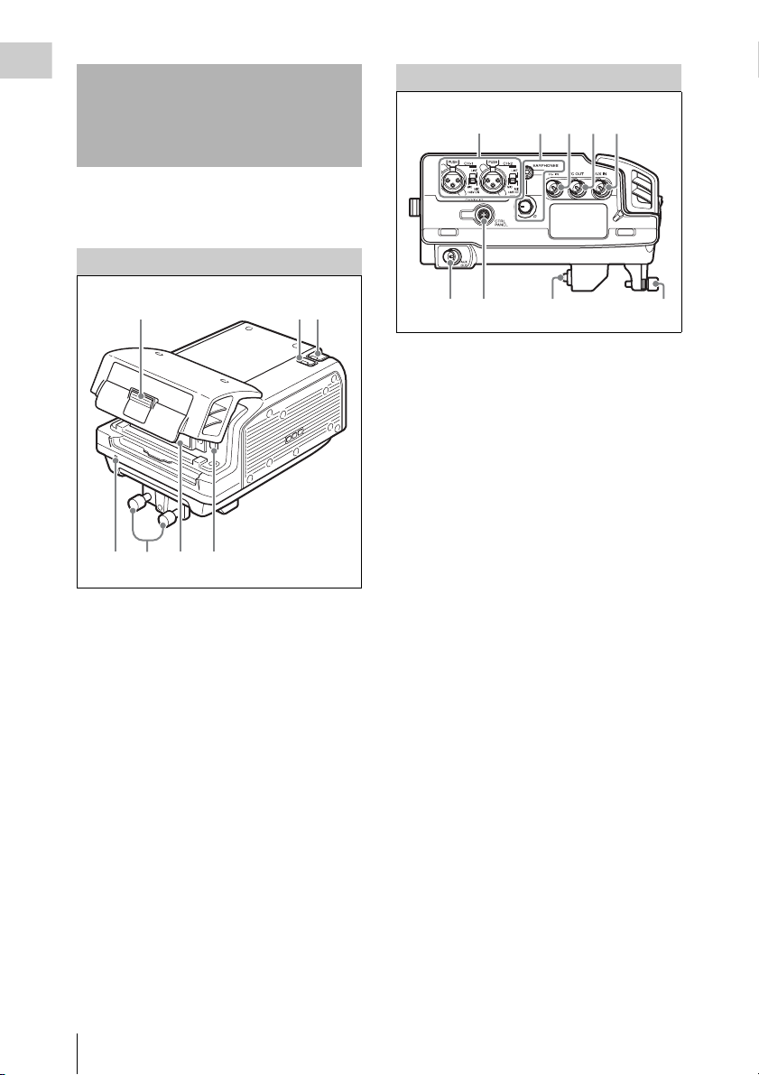
Overall View
Left Side View
321
45
1
23
4576
1. Lid open/close button (page 22)
2. Tally indicator (page 22)
Lights up during recording.
Flashes as a warning indication when an
error or problem has occurred.
3. POWER (power supply) indicator
(page 21)
Lights up in green when power to the unit is
on.
4. EJECT button (page 23)
5. SRMemory card slot (page 22)
6. Docking screws (page 18)
7. LID LOCK indicator (page 22)
Lights up in orange when an SRMemory card
is mounted.
98 7 6
1. AUDIO INPUT CH-1, CH-2 (analog audio
input channel 1, 2) connectors (3-pin XLR,
female) and input selection switches
Set the input selection switches as follows,
depending on the type and level of the input
audio.
LINE: For line input
MIC: For microphone input
MIC +48V ON: For input from microphones
with external power supply
2. EARPHONES jack (stereo mini jack) and
LEVEL knob
Adjusts the audio level.
A warning/alarm tone is also output via this
jack when an error is detected.
3. TC IN (time code input) connector (BNC)
Connect to the time code output connector of
an external device such as a time code
generator or VTR. Use this connector when
locking the internal time code generator to
external time code.
4. TC OUT (time code output) connector
(BNC)
Connect to the time code input connector of
an external device such as a time code reader
or VTR. Signal is supplied according to
setting made from TC Setup menu, OTHERS
>TC OUT. (see page 41)
5. AUX IN (for future use)
6. Docking screws (page 18)
7. CAMERA connector (page 17)
8. CTRL PANEL (Control Panel) connector
(page 16)
9. AUX OUT connector (for future use)
10
Names of Parts

Rear and Right Side View
Chapter 1 Overview
1
2
3
1. Power switch (page 21)
Setting the switch to the ? side turns power
on, and setting the switch to the 1 side turns
power off.
2. Cable clamp (page 16)
3. Fan
Note
Do not block the ventilation openings.
Otherwise internal heat buildup can lead to a risk of
fire and damage to the unit.
Names of Parts
11
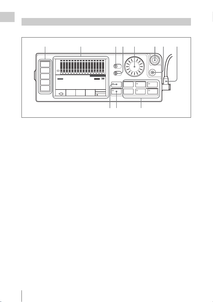
Control Panel (SRK-CP1, Option)
Chapter 1 Overview
For information on how to use the control panel, see “Basic Menu Operations” (page 25).
1
HOME
TC
VIDEO
AUDIO
SYSTEM
SDI
SDI
dB
0
-10
-20
-30
-60
EMP
EMP
EE
L R
L R
1
2
TCG
00H 00M 00S 00F
16.5V
2345678
SDI
SDI
SDI
SDI
SDI
SDI
SDI
SDI
SDI
SDI
EMP
EMP
EMP
EMP
EMP
EMP
EMP
EMP
EMP
L R
7
ENCODE
STANDARD
EMP
L R
L R
L R
L R
L R
8
9
10
11
12
F65RAW
23.98P
L R
L R
L R
L R
3
4
5
6
STOP
REMAIN
10min
1. Menu selection buttons (page 25)
For information on menu items, see “Menu
Details” (page 40).
2. Display (page 13)
3. KEY INHI (key inhibit) switch (page 26)
4. LIGHT switch (page 28)
Setting this switch to ON turns the backlight
on.
5. ADJUST knob
Serves to adjust audio levels etc.
6. SELECT/ENTER dial (page 25)
Serves to make menu selections etc. Rotate
the dial to move the cursor and press the dial
to change and confirm settings.
7. BACK button (page 25)
When a menu is displayed, you can press this
button to back up one level in the menu
structure.
8. Control panel connection cable (page 16)
9. Record/Play buttons (page 34, 36, 37)
Use these buttons to play recordings and
files.
The functions of the buttons change when
they are pressed together with the FUNC
button.
10. FUNC (Function) button (page 37)
Holding down this button changes the
operation of the Record/Play buttons.
11. EJECT button and indicator (page 23)
SDI
SDI
SDI
SDI
EMP
EMP
EMP
EMP
L R
L R
L R
L R
13
14
15
16
SR-R4:CAM
KEY
INHI
RECINHI
LOCAL
EE
21:46
11 10 9
KEY INHI
OFF ON
LIGHT
OFF ON
EJECT STOP PLAY
xZzB
REW F FWD PAUSE
FUNC
mXM
ADJUST
SELECT/ENTER
BACK
REC
Note on faulty pixels on the LCD panel
The LCD panel fitted to this unit is manufactured
with high precision technology, giving a
functioning pixel ratio of at least 99.99%. Thus a
very small proportion of pixels maybe “stuck”,
either always off (black), always on (red, green,
or blue), or flashing. In addition, over a long
period of use, because of the physical
characteristics of the liquid crystal display, such
“stuck” pixels may appear spontaneously. These
problems are not a malfunction. Note that any
such problems have no effect on recorded data.
12
Names of Parts
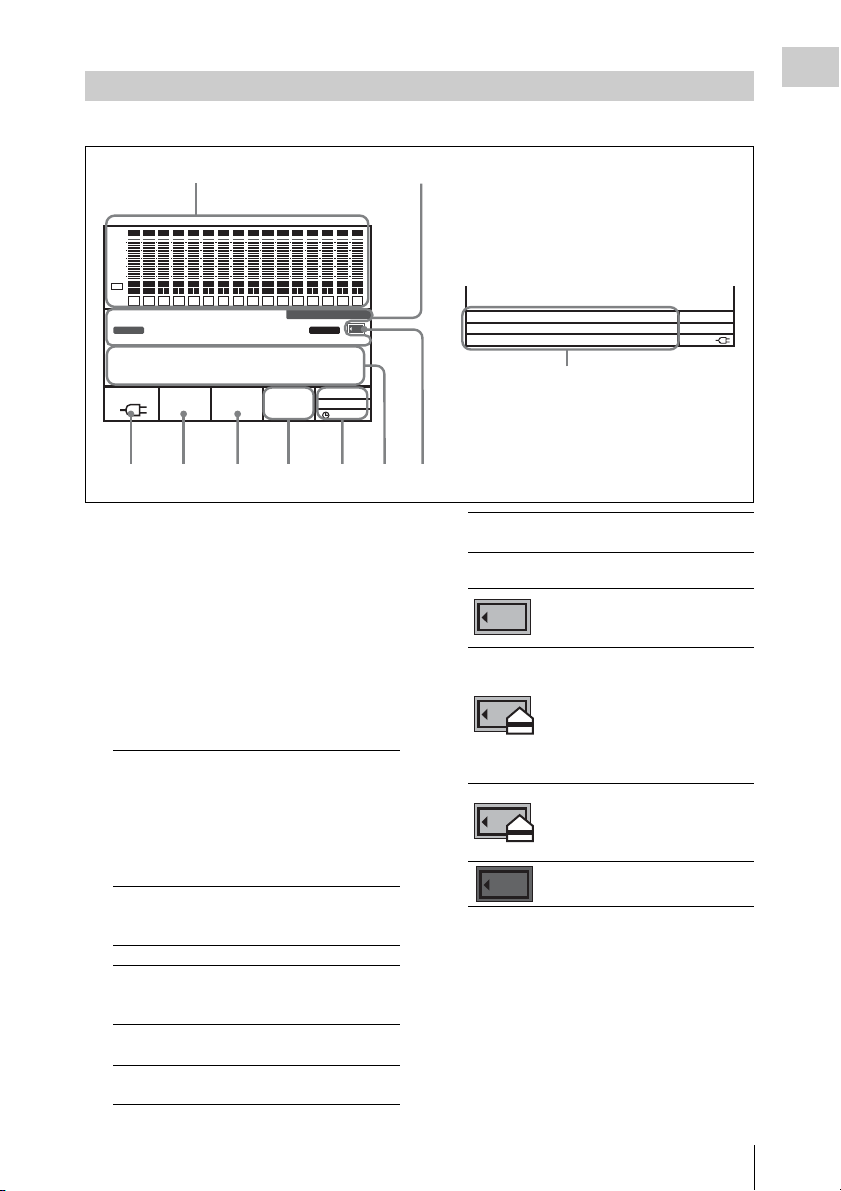
Display
00H00M00S00
The condition shown below is called the HOME screen in this manual.
Chapter 1 Overview
1
SDI
SDI
SDI
SDI
SDI
SDI
SDI
SDI
SDI
SDI
SDI
SDI
SDI
SDI
SDI
EMP
EMP
L R
13
SR-R4:CAM
KEY
SDI
EMP
EMP
EMP
L R
L R
L R
14
15
16
INHI
RECINHI
dB
0
-10
-20
-30
-60
EMP
EMP
EMP
EMP
EMP
EMP
EMP
EMP
EMP
EMP
EE
L R
L R
L R
L R
L R
1
TCG
L R
2
3
4
5
6
STOP
EMP
L R
L R
L R
L R
L R
7
L R
8
9
10
11
12
00H 00M 00S 00F
LOCAL
F65RAW
ENCODE
REMAIN
16.5V
10min
STANDARD
23.98P
1. Audio level meters
Show the recording level in recording and EE mode. During playback, the meters show
the playback level.
The top row indicates the audio input signal
that is being recorded.
The numbers 1 to 16 in the bottom row
indicate the track number of the file.
2. Operation status and warning indicator
Shows the operation status of the unit as well
as various warning indications.
SR-R4:
CAM
TCR/TCG/
UBR/UBG/
TM1/TM2
LTC/VITC Time code is being shown.
DF/NDF System is in DF (drop-frame) or
EXT-LK Time code is locked to external
KEY INHI KEY INHI switch is ON. (see
The background color is red
when the unit is operating in
recording mode, and blue when
operating in playback mode.
The mode is changed using
RECORDER/PLAYER in the
VIDEO Setup menu.
Time data type.
NDF (non-drop frame) mode.
(see page 41)
time code.
page 26)
21:46
EE
2
Sections 4 to 7 change to the condition
shown as 10 below when the HOME
button is pressed while holding down the
FUNC button.
F
SYS:
EMCODE:
PB:
F65RAW 23.98P
STANDARD
F65RAW 23.98P
LOCAL
---
16.5V
10
4356789
REC INHI SRMemory card is write-
3. SRMemory card icon indications
4. Time data indication
Shows the time data for the current position
in the file.
protected. (see page 23)
Mounting/mounted
An SRMemory card is inserted
and the lid is locked.
Unmounting (cursor section in the
bottom right flashes)
The EJECT button has been
pressed and the unit is
transitioning to the state in which
you can remove the SRMemory
card.
UNMOUNT state
The lid lock has been released and
the SRMemory card can be
removed.
There is no SRMemory card in the
unit. (off)
Names of Parts
13
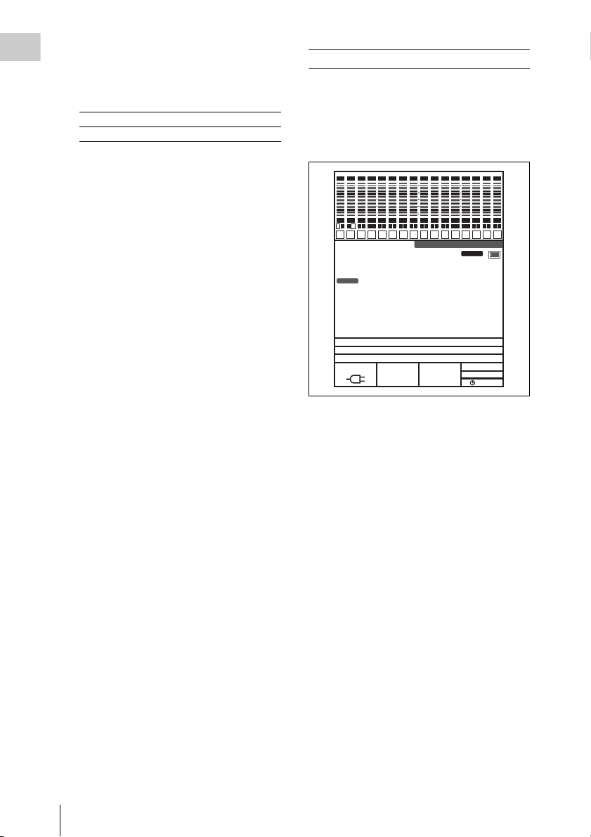
5. Status indication
Chapter 1 Overview
Shows the control mode of the unit
(LOCAL), power mode (EE), and current
time.
Top row Shows LOCAL always.
Bottom row Shows the current time.
6. Signal format indication
Shows the format of the signal being
recorded.
7. Encoding format indication (page 57)
Shows the encoding and bit rate settings used
for recording.
8. SRMemory card remaining capacity
indication
Shows the remaining space on the
SRMemory card calculated as remaining
time, using the current recording settings.
When the remaining time is less than 3
minutes, the indication flashes.
9. Power supply voltage indication (page 21)
Shows the power supply voltage.
10. Signal format indication (page 27)
When the FUNC and HOME buttons are
pressed simultaneously, the signal formats
are displayed from top to bottom in system,
encoding, playback file name sequence, or in
playback file output, recording date, duration
sequence.
To switch display to portrait mode
Press the HOME button while holding down the
FUNC and BACK buttons to switch the display to
portrait mode (rotate display 90° to the left).
To return to landscape mode, press the HOME
button again while holding down the FUNC and
BACK buttons.
SDI
SDI
SDI
SDI
SDI
SDI
SDI
SDI
SDI
SDI
SDI
SDI
SDI
SDI
SDI
SDI
EM
EM
EM
EM
EM
EM
EM EM
L R
L R
L R
L R
L R
1
2
3
4
STOP
TCG
00H00M04S22
SYS:F65RAW 23.98P
ENCODE:STANDARD
FILENAME:
16.7V
EM
EM
EM
EM
EM
EM
EM
L R
L R
L R
L R
L R
L R
5
6
7
L R
8
9
10
11
12
SR-R4:CAM
EM
L R
L R
L R
L R
13
14
15
16
KEY
INHI
RECINHI
F
REMAIN
77min
F65RAW
23.98P
LOCAL
19:47
EE
14
Names of Parts

Chapter 2 Preparation
Work Flow
The steps that are required before starting to use
the SR-R4 are listed below.
When mounting Control Panel (SRK-CP1,
Option) on the unit
Mount control panel on unit (page 15)
Connect F65 (page 17)
Turn power on (page 21)
Insert SRMemory card (page 22)
When mounting Control Panel (SRK-CP1,
Option) on the F65
Connect F65 (page 17)
Mount control panel on the F65 (page 19)
Turn power on (page 21)
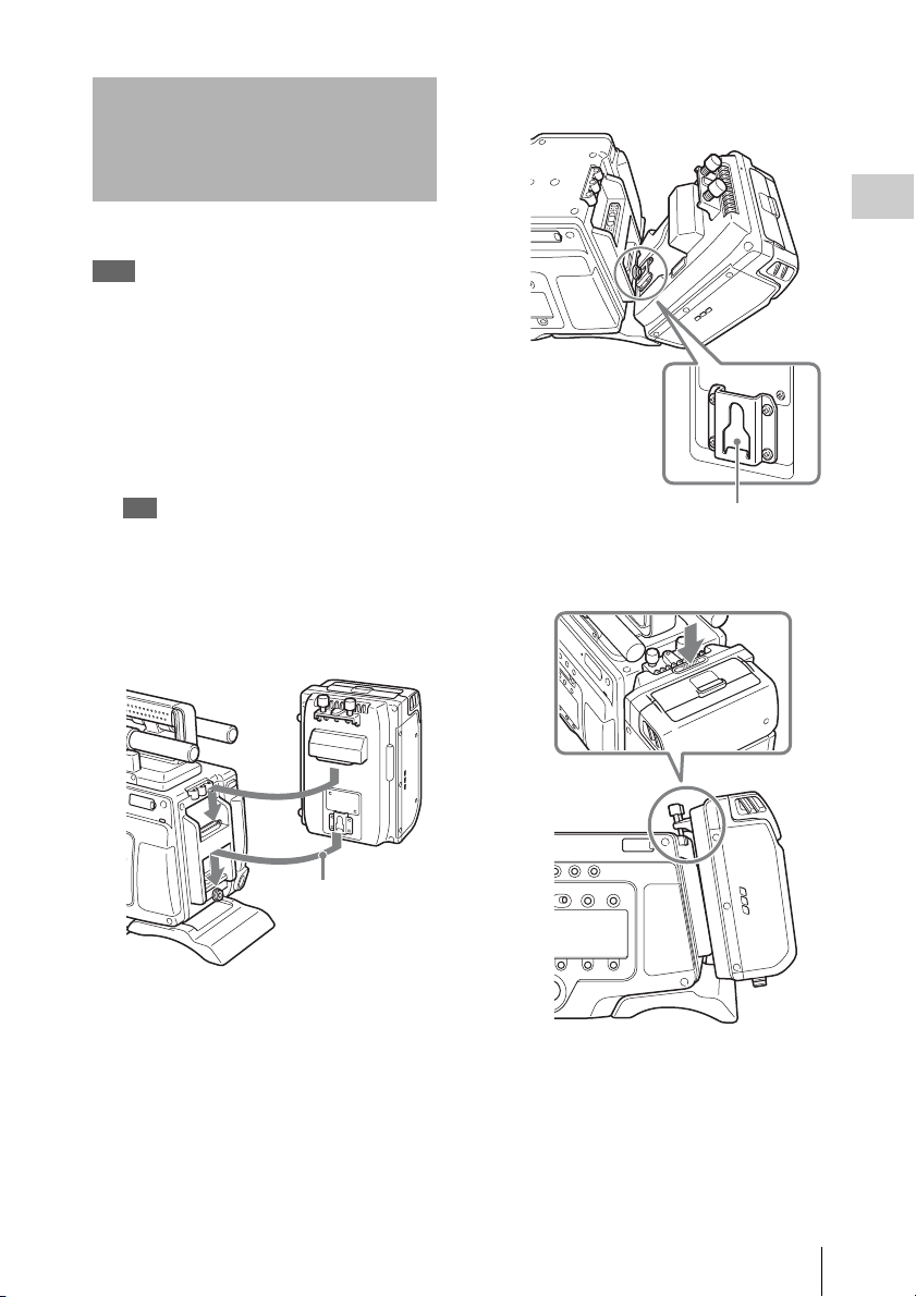
Mount Control Panel on Unit
Attach the CP bracket supplied with the Control
Panel (SRK-CP1, Option) to the unit, and connect
the unit and the control panel with the control
panel cable.
1 Attach the CP bracket supplied with the
control panel to the right side of the
unit.
2 Slide the control panel into the CP
bracket.
Chapter 2 Preparation
Insert SRMemory card (page 22)
Tip
A Phillips (cross head) screwdriver is required for
mounting the control panel.
Work Flow / Mount Control Panel on Unit
15
3 Use the supplied control panel cable to
connect the unit and the control panel.
Chapter 2 Preparation
4 Use the cable clamp as shown, to fix the
cable.
To remove the control panel
Grasp the underside of the CP bracket and push it
in the B direction to release the lock. Then slide
the control panel out.
Notes
• Do not cross the cord below the clamps.
• Make sure that the bottom of the cord does not
extend beyond the bottom of the SR-R4.
• If the SR-R4 cannot be docked on the F65, refer
to the above and check the cord bundle again.
Note
Always turn off the power supply for the unit before
disconnecting the control panel cable and removing the
control panel.
Mount Control Panel on Unit
16
Connect F65
1 Align the base of the unit with the base
of the F65 as shown in the diagram.
The unit mounts onto the rear of the F65.
Tips
• When mounting the unit, first mount the F65 on
a tripod and secure it such that it does not move.
For details of mounting on a tripod, refer to the
Operation Manual for the F65.
• When mounting the unit, do so in an
environment relatively free from dust, etc.
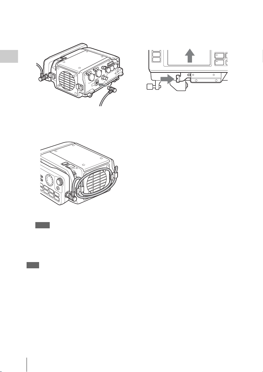
1 Remove the connector cap from the
CAMERA connector of the unit.
Tip
Store the connector cap in a safe location so that you
do not lose it.
2 Align and connect the CAMERA
connector of the unit with the F65
connector.
Chapter 2 Preparation
Couple the unit in the orientation shown.
2 Align the CAMERA connector of the
unit with the F65 dock connector, and
push the unit down.
First, join as shown.
Connect F65
17
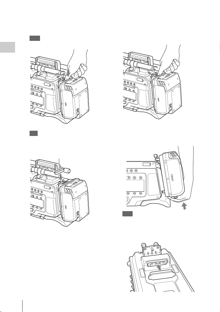
3 Press down firmly on the point shown in
the diagram, and fasten the docking
screws.
Note
Do not push down on the lid.
Chapter 2 Preparation
Removing the Unit from the F65
1 Press down firmly on the point shown in
the diagram, and loosen the docking
screws.
Tip
You can leave the connector cap, which was
removed from the CAMERA connector, attached to
the docking screws.
Connector cap
2 Remove the unit by lifting it.
When lifting, hold the unit as close as
possible to the F65 and pull it up.
Note
Do not push on the ventilation openings.
3 Attach the connector cap to the
CAMERA connector of the unit.
18
Connect F65

Mount Control Panel on the F65
3 Slide the control panel into the CP
bracket.
Attach the Control Panel (SRK-CP1, Option) to
the F65, and connect the unit and the control
panel with the control panel cable.
1 Attach the outside bracket supplied
with the control panel to the side of the
F65, and fasten using the 4 supplied
screws (M3 × 5).
There are 2 types of outside bracket. Attach
the larger outside bracket to an F65 with a
mechanical shutter or the smaller outside
bracket to an F65 without a mechanical
shutter.
Screws (M3 × 5)
Chapter 2 Preparation
4 Use the supplied control panel cable to
connect the unit and the control panel.
5 Use the cable clamp as shown to fix the
cable.
2 Attach the CP Bracket to the outside
bracket.
Note
Always turn off the power supply for the unit before
disconnecting the control panel cable and removing
the control panel.
Mount Control Panel on the F65
19
 Loading...