

Sony SR-R1, SRK-R311 Operation Manual

HD PORTABLE MEMORY RECORDER
SR-R1
HQ RECORDER OPTION
SRK-R311
OPERATION MANUAL [English]
1st Edition

Before operating the unit, please read this
manual thoroughly and retain it for future
reference.
WARNING
To reduce the risk of fire or
electric shock, do not
expose this apparatus to
rain or moisture.
To avoid electrical shock,
do not open the cabinet.
Refer servicing to qualified
personnel only.
Do not install the appliance in a confined
space, such as book case or built-in cabinet.
IMPORTANT
The nameplate is located on the bottom.
WARNING
Excessive sound pressure from earphones
and headphones can cause hearing loss.
In order to use this product safely, avoid
prolonged listening at excessive sound
pressure levels.
For the customers in the U.S.A.
This equipment has been tested and found
to comply with the limits for a Class B digital
device, pursuant to Part 15 of the FCC
Rules. These limits are designed to provide
reasonable protection against harmful
interference in a residential installation. This
equipment generates, uses, and can radiate
radio frequency energy and, if not installed
and used in accordance with the
instructions, may cause harmful interference
to radio communications. However, there is
no guarantee that interference will not occur
in a particular installation. If this equipment
does cause harmful interference to radio or
television reception, which can be
determined by turning the equipment off and
on, the user is encouraged to try to correct
the interference by one or more of the
following measures:
- Reorient or relocate the receiving
antenna.
- Increase the separation between the
equipment and receiver.
- Connect the equipment into an outlet on a
circuit different from that to which the
receiver is connected.
- Consult the dealer or an experienced
radio/TV technician for help.
You are cautioned that any changes or
modifications not expressly approved in this
manual could void your authority to operate
this equipment.
All interface cables used to connect
peripherals must be shielded in order to
comply with the limits for a digital device
pursuant to Subpart B of Part 15 of FCC
Rules.
This device complies with Part 15 of the FCC
Rules. Operation is subject to the following
two conditions: (1) this device may not cause
harmful interference, and (2) this device
must accept any interference received,
including interference that may cause
undesired operation.
For the customers in Canada
This Class B digital apparatus complies with
Canadian ICES-003.
For the customers in Europe
This product with the CE marking complies
with the EMC Directive issued by the
Commission of the European Community.
Compliance with this directive implies
conformity to the following European
standards:
• EN55103-1 : Electromagnetic
Interference(Emission)
• EN55103-2 : Electromagnetic
Susceptibility(Immunity)
This product is intended for use in the
following Electromagnetic Environments: E1
(residential), E2 (commercial and light
industrial), E3 (urban outdoors), E4
(controlled EMC environment, ex. TV
studio).
2
For the customers in Europe
The manufacturer of this product is Sony
Corporation, 1-7-1 Konan, Minato-ku,
Tokyo, Japan.
The Authorized Representative for EMC and
product safety is Sony Deutschland GmbH,
Hedelfinger Strasse 61, 70327 Stuttgart,
Germany. For any service or guarantee
matters please refer to the addresses given
in separate service or guarantee documents.
For the State of California, USA only
Perchlorate Material - special handling may
apply, See
www.dtsc.ca.gov/hazardouswaste/
perchlorate
Perchlorate Material : Lithium battery
contains perchlorate.
For the customers in Taiwan only
Avant d'utiliser l'appareil, veuillez lire
attentivement ce manuel et le conserver
pour future référence.
AVERTISSEMENT
Afin de réduire les risques
d’incendie ou
d’électrocution, ne pas
exposer cet appareil à la
pluie ou à l’humidité.
Afin d’écarter tout risque
d’électrocution, garder le
coffret fermé. Ne confier
l’entretien de l’appareil
qu’à un personnel qualifié.
Ne pas installer l’appareil dans un endroit
confiné, par exemple une bibliothèque ou un
placard encastré.
IMPORTANT
La plaque signalétique se situe sous
l’appareil.
AVERTISSEMENT
Une pression acoustique excessive en
provenance des écouteurs ou du casque
peut provoquer une baisse de l'acuité
auditive.
Pour utiliser ce produit en toute sécurité,
évitez l'écoute prolongée à des pressions
sonores excessives.
Pour les clients au Canada
Cet appareil numérique de la classe B est
conforme à la norme NMB-003 du Canada.
Pour les clients en Europe
Ce produit portant la marque CE est
conforme à la Directive sur la compatibilité
électromagnétique (EMC) émise par la
Commission de la Communauté
européenne.
La conformité à cette directive implique la
conformité aux normes européennes
suivantes :
3

• EN55103-1 : Interférences
électromagnétiques (émission)
• EN55103-2 : Sensibilité
électromagnétique (immunité)
Ce produit est prévu pour être utilisé dans
les environnements électromagnétiques
suivants : E1 (résidentiel), E2 (commercial et
industrie légère), E3 (urbain extérieur) et E4
(environnement EMC contrôlé, ex. studio de
télévision).
Pour les clients en Europe
Le fabricant de ce produit est Sony
Corporation, 1-7-1 Konan, Minato-ku,
Tokyo, Japon.
Le représentant autorisé pour EMC et la
sécurité des produits est Sony Deutschland
GmbH, Hedelfinger Strasse 61, 70327
Stuttgart, Allemagne. Pour toute question
concernant le service ou la garantie, veuillez
consulter les adresses indiquées dans les
documents de service ou de garantie
séparés.
Bitte lesen Sie dieses Handbuch vor der
Benutzung des Geräts sorgfältig durch und
bewahren Sie es zum späteren
Nachschlagen auf.
WARNUNG
Um die Gefahr von Bränden
oder elektrischen Schlägen
zu verringern, darf dieses
Gerät nicht Regen oder
Feuchtigkeit ausgesetzt
werden.
Um einen elektrischen
Schlag zu vermeiden, darf
das Gehäuse nicht geöffnet
werden. Überlassen Sie
Wartungsarbeiten stets nur
qualifiziertem
Fachpersonal.
Das Gerät nicht an Orten aufstellen, z.B. in
Bücherregalen oder Einbauschränken, wo
keine ausreichende Belüftung gewährleistet
ist.
WICHTIG
Das Namensschild befindet sich auf der
Unterseite des Gerätes.
WARNUNG
Zu hoher Schalldruck von Ohrhörern und
Kopfhörern kann Gehörschäden
verursachen.
Um dieses Produkt sicher zu verwenden,
vermeiden Sie längeres Hören bei sehr
hohen Schalldruckpegeln.
Für Kunden in Europa
Dieses Produkt besitzt die CEKennzeichnung und erfüllt die EMVRichtlinie der EG-Kommission.
Angewandte Normen:
• EN55103-1: Elektromagnetische
Verträglichkeit (Störaussendung)
4

• EN55103-2: Elektromagnetische
Verträglichkeit (Störfestigkeit)
Für die folgenden elektromagnetischen
Umgebungen: E1 (Wohnbereich), E2
(kommerzieller und in beschränktem Maße
industrieller Bereich), E3 (Stadtbereich im
Freien) und E4 (kontrollierter EMV-Bereich,
z.B. Fernsehstudio).
Für Kunden in Europa
Der Hersteller dieses Produkts ist Sony
Corporation, 1-7-1 Konan, Minato-ku,
Tokyo, Japan.
Der autorisierte Repräsentant für EMV und
Produktsicherheit ist Sony Deutschland
GmbH, Hedelfinger Strasse 61, 70327
Stuttgart, Deutschland. Bei jeglichen
Angelegenheiten in Bezug auf Kundendienst
oder Garantie wenden Sie sich bitte an die in
den separaten Kundendienst- oder
Garantiedokumenten aufgeführten
Anschriften.
5

Table of Contents
Chapter 1 : Overview
Features................................................... 8
System Configuration Example............ 9
Names of Parts...................................... 10
Overall View ............................. 10
Left Side View........................... 10
Rear and Right Side View......... 11
Control Panel............................. 12
Display...................................... 13
Chapter 2 : Preparation
Work Flow ............................................ 15
Mount Control Panel........................... 15
Connect Power .................................... 16
Using AC Power........................ 16
Using the Battery Pack.............. 16
Connect HD SDI Compliant
Equipment ...................................... 19
Connecting a Camera/
Camcorder........................... 19
Connecting an HD Monitor....... 20
About the Reference Sync
Signal ................................. 21
Turn Power On .................................... 22
Insert SRMemory Card ..................... 23
Inserting and Removing the
SRMemory Card ................. 23
Formatting an SRMemory Card
(File System Format ) ......... 24
Chapter 3 : Basic Menu Operations
Buttons Used for Menu
Operations........................... 25
Serve for Selecting a Menu ....... 25
Locking the Controls................. 26
Signal Format Settings......................... 27
Selecting the Signal Format....... 27
Display Settings ................................... 28
Using the Backlight ................... 28
Using the Screen Saver.............. 28
Power Save Settings ............................. 28
Storing and Recalling Setup Data....... 29
Date Settings ......................................... 31
Recording Line Settings for Input
Metadata......................................... 32
Chapter 4 : Recording and Playback
Recording Preparations and
Operations ...................................... 33
Setting the Audio Signals .......... 33
Setting the Recording Levels..... 34
Setting the Time Code and User
Bits ..................................... 35
Recording .................................. 38
Playback Preparations and
Operations ...................................... 38
Making Settings Related to Audio
Monitor Signals................... 38
Adjusting Playback Audio
Levels ................................. 38
Selecting the Time Data to Display
During Playback.................. 38
Playback .................................... 39
How to Use the Recording and Playback
Operation Buttons.......................... 40
Making Superimpose Settings............. 41
FILE LIST Operations........................ 42
Displaying a File List ................ 42
Performing File Operations....... 43
Table of Contents
6

Changing the File Display
Order ................................... 44
Timer Rec ............................................. 44
Cache Rec ............................................. 46
SR Motion............................................. 47
SR Motion Operation Flow ....... 51
Target Frame Frequencies and
Signal Formats .................... 52
Select FPS Function .................. 53
Interval Frame Function ............ 59
Monitor LUT Function........................ 66
Chapter 5 : Menu Details
TC Setup Menu .................................... 69
VIDEO Setup Menu............................. 73
AUDIO Setup Menu ............................ 74
SYSTEM Setup Menu ......................... 78
Maintenance and Inspections.............. 85
Note About the Power Supply
Terminal.............................. 85
Specifications........................................ 85
General ...................................... 85
Video ......................................... 86
Audio......................................... 86
Input/Output Connectors ........... 86
Supplied Accessories................. 87
Optional Accessories................. 87
Error Messages and Warning
Messages ......................................... 88
About Error Messages............... 88
About Warning Messages ......... 89
Warning System................................... 91
About SRK-R311 ................................. 92
Troubleshooting ................................... 92
About Recording/Playback
Formats........................................... 97
List of Camera Combinations and
Available Functions....................... 98
About “Memory Stick” Media............ 99
MPEG-4 VISUAL PATENT
PORTFOLIO LICENSE............. 101
Index.................................................... 102
Table of Contents
7

Chapter 1 Overview
Chapter 1 Overview
Features
The SR-R1 is a portable memory recorder of the
SRMASTER series that has 1.5G/3G SDI Dual
Link input/output and uses the newly developed
SRMemory card for recording media.
SRMASTER and SRMemory are trademarks of
Sony Corporation.
High Quality Recording
Support for SR-SQ (440 Mbps) and SR-Lite
(220 Mbps) is provided as standard.
The optional SRK-R311 is also available (sold
separately) to enable support for SR-HQ (10-bit/
12-bit, 880 Mbps) and uncompressed DPX
recording.
There is 16-channel (uncompressed, 24-bit,
48 kHz) support for audio.
camcorders, so recording can be linked to Rec/
Stop on the camera side.
HDW-F900R/650 dockable operation
The SR-R1 supports dockable operation with the
HD CAM camcorder HD W-F900R/650 equipped
with HD SDI output, using the Docking Plate
SRK-R302 (sold separately).
Use as PMW-F3 storage
The SR-R1 can be used as high-quality online
storage for the Digital Cinema Recorder PMWF3. Simultaneous recording on the SxS memory
card in the PMW-F3 and the SRMemory card is
possible. By synching delay and time code
information on both media, an efficient workflow
can be assured.
RGB 4:4:4/60p/3D Creation
The SR-R1 is equipped with 1.5G/3G SDI Dual
Link and includes recording capabilities such as
60p of RGB 4:4:4 and 3D (L/R) to enable support
for various scenes.
SR Motion
The SR Motion function and Timer/Cache Rec
functions are incorporated as standard, enabling
recordings with slow and quick motion effects
while maintaining high image quality.
RS-422A Interface
Connect the supplied cable to the REMOTE
connector to enable external RS-422A control.
HD SDI Remote
Support is provided for the HD SDI Remote
function that is incorporated in many Sony
Features
8
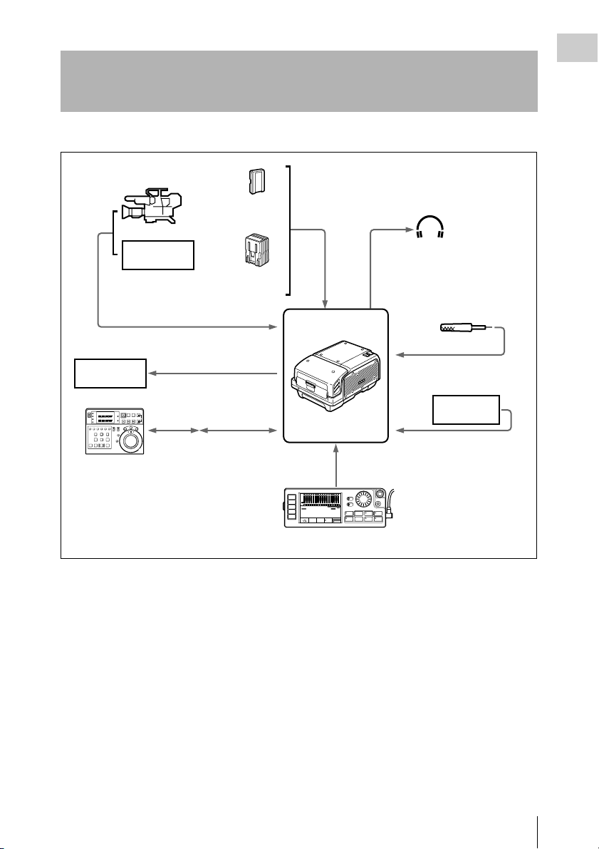
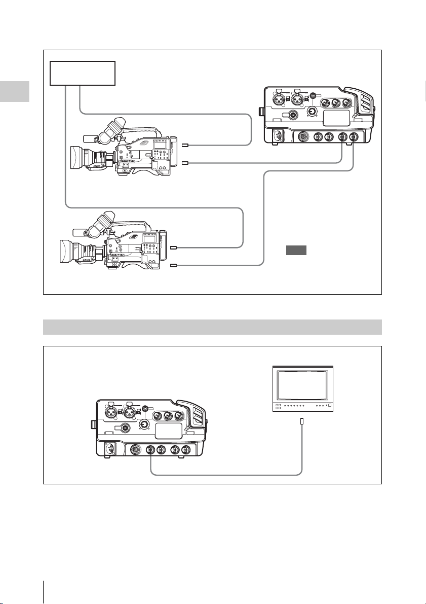
System Configuration Example
The following figure shows a system configured around the SR-R1.
HD color video camera
BP-GL95
+
BKP-L551
HD VTR etc.
AC-DN10/
DN2B
HD SDI video/
audio input
DC IN
Earphones/
Headphones
Audio input
Chapter 1 Overview
HD VTR etc.
RM-280
Editing Controller
HD SDI video/audio output
9-pin
remote
control
REMOTE
cable (included)
REMOTE IN
SR-R1
CTRL PANEL
SDI
SDI
SDI
SDI
SDI
SDI
SDI
SDI
SDI
SDI
SDI
SDI
SDI
SDI
SDI
SDI
dB
0
-10
HOME
-20
-30
-60
EE
TC
VIDEO
TCG
AUDIO
00H00 M00S 00F
SYSTEM
16.5V
EMP
LR
1
KEY INHI
OFF ON
EMP
EMP
EMP
EMP
EMP
EMP
EMP
EMP
EMP
EMP
EMP
EMP
EMP
LR
LR
LR
LR
LR
LR
LR
LR
LR
LR
LR
LR
LR
2
3
4
5
6
7
8
9
10
11
12
13
14
SR-R1
STOP
KEY
INHI
LOCAL
1920x1080
ENCODE
REMAIN
M
59.94I
SR-SQ
10min
4:2:2
12bit
21:46
SELECT/ENTER
EMP
EMP
LIGHT
LR
LR
15
16
OFF ON
ADJUST
RECINHI
EJECT STOP PLAY
REC
xZzB
REW F FWD PAUSE
FUNC
mXM
EE
Control Panel (included)
Microphone
Analog: 2 channels
Audio input
VTR etc.
AUX IN:16 channels
BACK
System Configuration Example
9

Chapter 1 Overview
Names of Parts
For detailed information on functions and usage, see
the pages indicated in brackets.
Overall View
Left Side View
321
4 5
1
4
56
23
1. Lid open/close button (page 23)
2. Tally indicator (page 22, 45, 91)
Lights up during recording.
Flashes as a warning indication when an
error or problem has occurred.
3. POWER (power supply) indicator
(page 22)
Lights up in green when power to the unit is
on.
4. EJECT button (page 24)
5. SRMemory card slot (page 23)
6. LID LOCK indicator (page 23)
Lights up in orange when an SRMemory card
is mounted.
10 9 8 7 6
1. AUDIO INPUT CH-1, CH-2 (analog audio
input channel 1, 2) connectors (3-pin XLR,
female) and input selection switches
Set the input selection switches as follows,
depending on the type and level of the input
audio.
LINE: For line input
MIC: For microphone input
MIC +48V ON: For input from microphones
with external power supply
2. EARPHONES jack (stereo mini jack) and
LEVEL knob
Adjusts the audio level.
A warning/alarm tone is also output via this
jack when an error is detected. (see page 91)
3. TC IN (time code input) connector (BNC)
Connect to the time code output connector of
an external device such as a time code
generator or VTR. Use this connector when
locking the internal time code generator to
external time code.
4. TC OUT (time code output) connector
(BNC)
Connect to the time code input connector of
an external device such as a time code reader
or VTR. Signal is supplied according to
setting made from TC Setup menu, OTHERS
>TC OUT. (see page 70)
5. AUX IN (SDI embedded audio input)
connector (BNC) (page 74)
Accepts audio input in up to 16 channels.
6. HD SDI IN (HD SDI signal input) A/B
(BNC) (page 19)
7. HD SDI OUT (MON) (HD SDI signal
output) connectors 1/2 (BNC) (page 19)
10
Names of Parts
8. REMOTE (remote control input)
connector (14-pin, female)
Using the supplied REMOTE cable, a 9-pin
remote cable (sold separately) can be used to
control the SR-R1 from other equipment.
Note
To enable remote control from other equipment via
this connector, access the SYSTEM Setup menu
and set REMOTE/LOCAL to “RMT” (see
page 80).
9. DC IN (DC power input) connector (4-pin
XLR, male) (page 16)
10. CTRL PANEL (Control Panel) connector
(page 16)
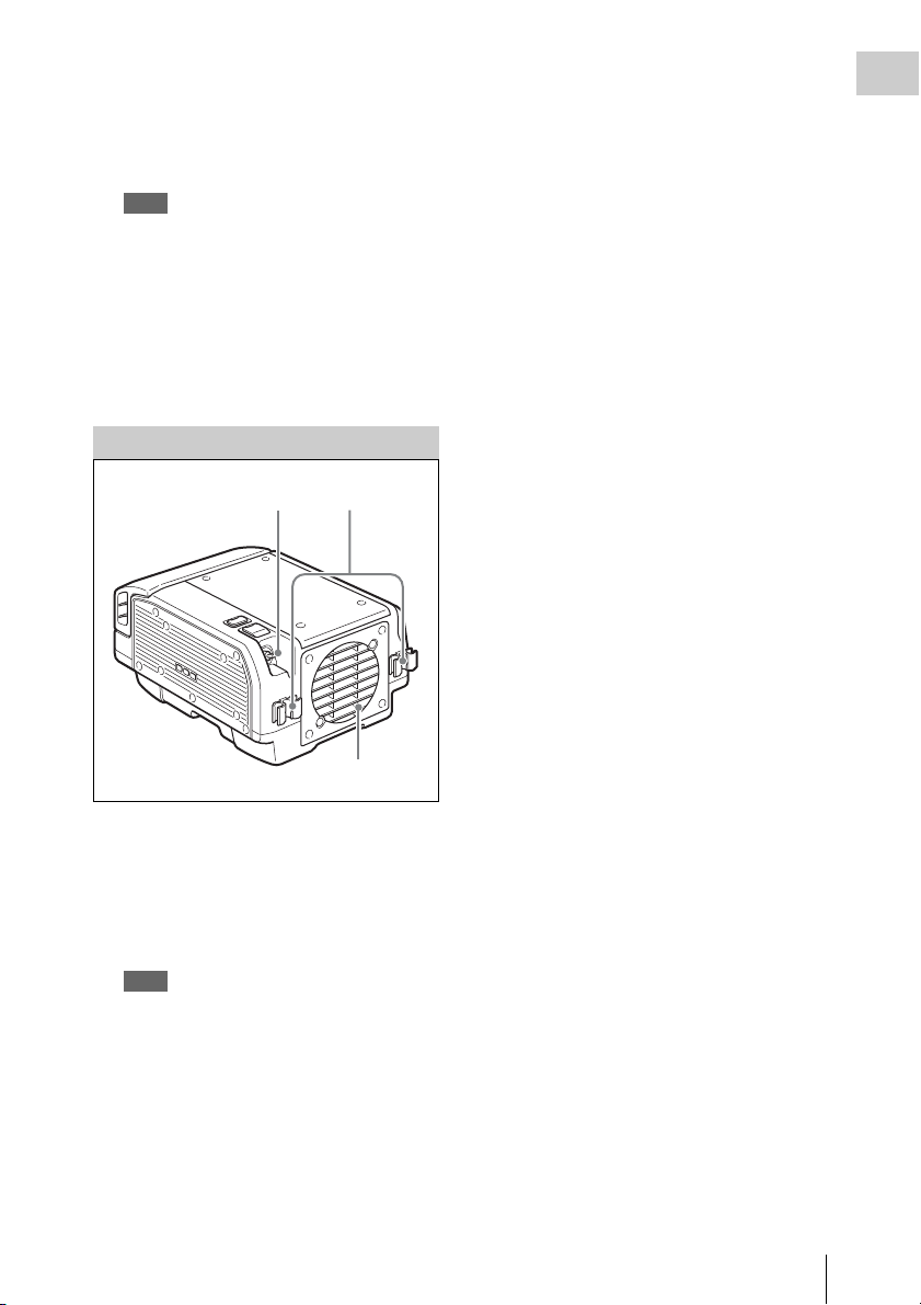
Rear and Right Side View
Chapter 1 Overview
1
2
3
1. Power switch (page 22)
Setting the switch to the ? side turns power
on, and setting the switch to the 1 side turns
power off.
2. Cable clamp (page 16)
3. Fan
Note
Do not block the ventilation openings.
Otherwise internal heat buildup can lead to a risk of
fire and damage to the unit.
Names of Parts
11

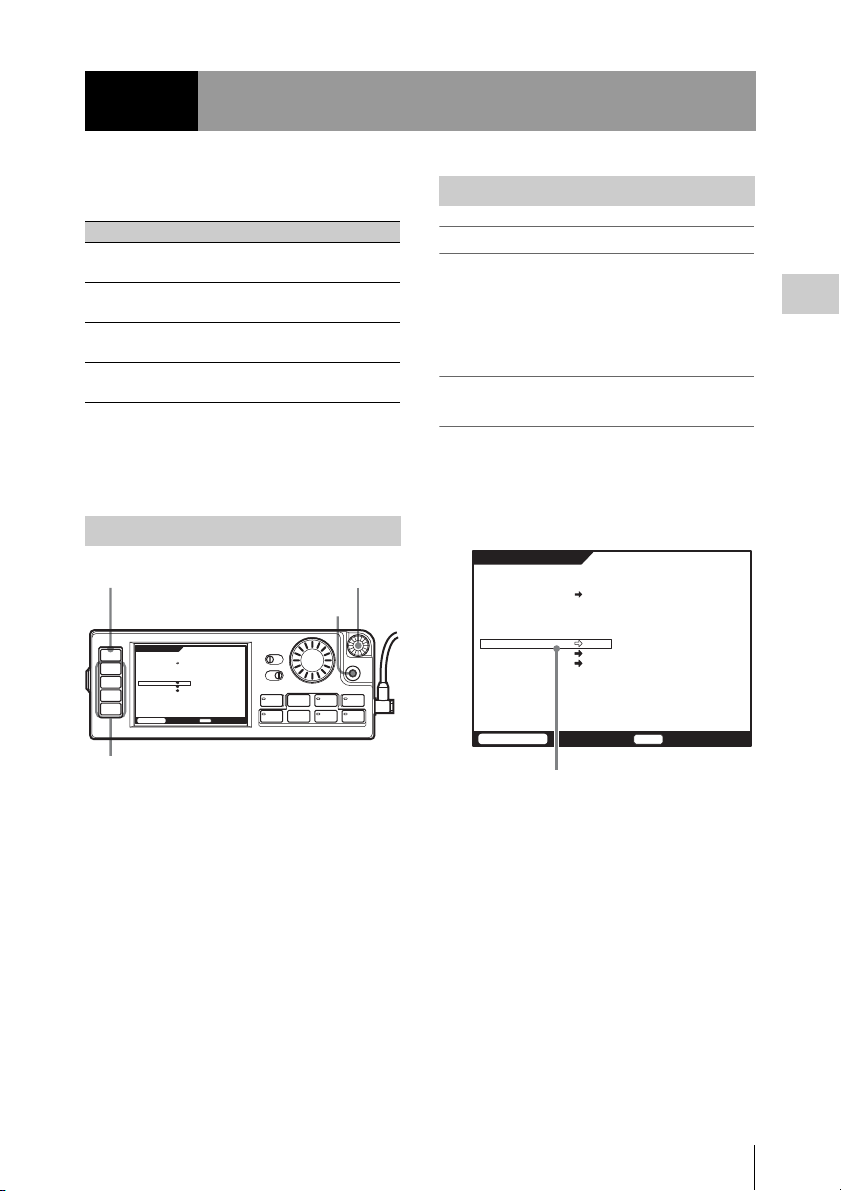
Control Panel
Chapter 1 Overview
For information on how to use the control panel, see “Basic Menu Operations” (page 25).
1
HOME
TC
VIDEO
AUDIO
SYSTEM
SDI
SDI
dB
0
-10
-20
-30
-60
EMP
EMP
EE
L R
L R
1
2
TCG
00H00M00S00
16.5V
2345678
SDI
SDI
SDI
SDI
SDI
SDI
SDI
SDI
SDI
SDI
SDI
SDI
SDI
SDI
KEY INHI
EMP
EMP
EMP
EMP
EMP
EMP
EMP
EMP
EMP
EMP
L R
L R
L R
L R
L R
3
4
5
6
7
STOP
ENCODE
REMAIN
SR-SQ
10min
12bit
EMP
L R
L R
L R
L R
L R
L R
8
9
10
11
12
13
SR-R1
KEY
1920x1080
M
59.94I
4:2:2
OFF ON
EMP
EMP
EMP
RECINHI
F
L R
16
OFF ON
LIGHT
EJECT STOP PLAY
xZzB
REW F FWD PAUSE
FUNC
mXM
L R
L R
14
15
INHI
LOCAL
EE
21:46
12 11 10 9
1. Menu selection buttons (page 25)
For information on menu items, see “Menu
Details” (page 69).
2. Display (page 13)
3. KEY INHI (key inhibit) switch (page 26)
4. LIGHT switch (page 28)
Setting this switch to ON turns the backlight
on.
5. ADJUST knob
Serves to adjust audio levels etc.
6. SELECT/ENTER dial (page 25)
Serves to make menu selections etc. Rotate
the dial to move the cursor and press the dial
to change and confirm settings.
7. BACK button (page 25)
When a menu is displayed, you can press this
button to back up one level in the menu
structure.
8. Control panel connection cable (page 16)
9. Record/Play buttons (page 38, 39, 40)
Use these buttons to play recordings and
files.
The functions of the buttons change when
they are pressed together with the FUNC
button.
10. FUNC (Function) button (page 40)
Holding down this button changes the
operation of the Record/Play buttons.
11. EJECT button and indicator (page 24)
12. “Memory Stick” slot (page 99)
SELECT/ENTER
BACK
ADJUST
REC
12
Names of Parts
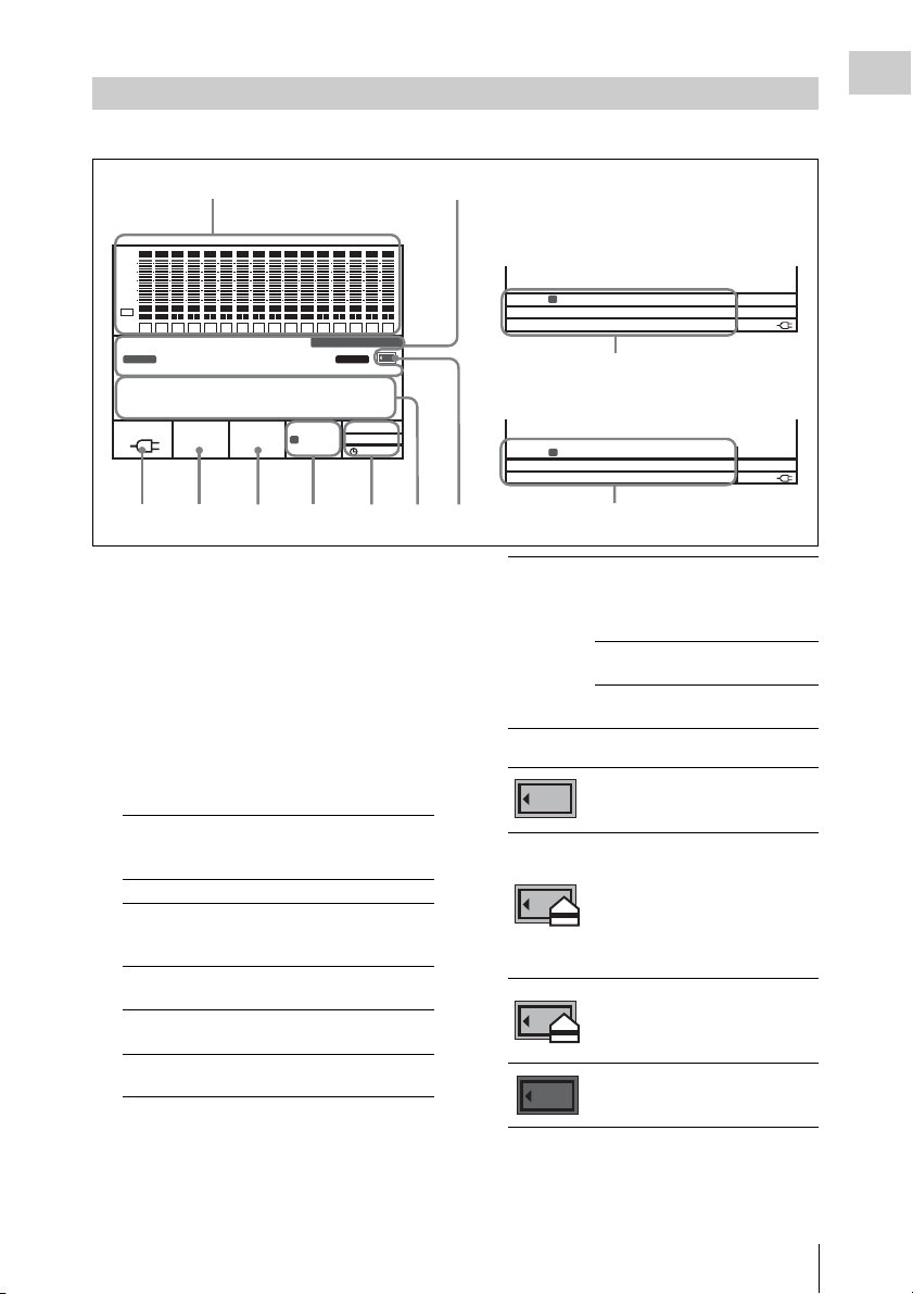
Display
00H00M00S00
00H26M02S12
The condition shown below is called the HOME screen in this manual.
Chapter 1 Overview
12
SDI
SDI
SDI
SDI
SDI
SDI
SDI
SDI
SDI
SDI
SDI
SDI
SDI
SDI
SDI
dB
0
-10
-20
-30
-60
EMP
EMP
EMP
EMP
EMP
EMP
EMP
EMP
EMP
EMP
EE
L R
L R
L R
L R
L R
1
TCG
L R
2
3
4
5
6
STOP
EMP
L R
L R
L R
L R
L R
7
8
9
10
11
SDI
EMP
EMP
EMP
EMP
EMP
L R
L R
L R
L R
L R
12
13
14
15
16
SR-R1
KEY
INHI
RECINHI
00H 00M 00S 00F
M
4:2:2
LOCAL
21:46
EE
16.5V
10min
SR-SQ
12bit
59.94I
1920x1080
ENCODE
REMAIN
1. Audio level meters
Show the recording level in recording and EE mode. During playback, the meters show
the playback level.
The top row indicates the audio input signal
that is being recorded.
The numbers 1 to 16 in the bottom row
indicate the track number of the file.
2. Operation status and warning indicator
Shows the operation status of the unit as well
as various warning indications.
TCR/TCG/
UBR/UBG/
TM1/TM2
LTC/VITC Time code is being shown.
DF/NDF System is in DF (drop-frame) or
EXT-LK Time code is locked to external
KEY INHI KEY INHI switch is ON. (see
REC INHI SRMemory card is write-
Time data type.
NDF (non-drop frame) mode.
(see page 70)
time code.
page 26)
protected. (see page 24)
Sections 4 to 7 change to the condition
shown as 9 and 10 below when the HOME
button is pressed while holding down the
FUNC button.
F
M
SYS:
1920x1080 59.94I 4:2:2
EMCODE:
SR-SQ 10bit
PB:
1920x1080 23PsF 422 SR-SQ 10bit
LOCAL
10min
16.5V
10
M
SYS:
1920x1080 59.94I 422
ENCODE:
SR-SQ 10bit
SIG:
8 FPS(MODE:(ON))
4356789
11
SR-R1 The model name is displayed as
follows, depending on the
operating status of the unit. (see
page 28)
*SR-R1 Power Save Mode
1.
**SR-R1 Power Save Mode
2.
3. SRMemory card icon indications
Mounting/mounted
An SRMemory card is inserted
and the lid is locked.
Unmounting (cursor section in the
bottom right flashes)
The EJECT button has been
pressed and the unit is
transitioning to the state in which
you can remove the SRMemory
card.
UNMOUNT state
The lid lock has been released and
the SRMemory card can be
removed.
MEMORY OUT state (off)
There is no SRMemory card in the
unit.
LOCAL
10min
16.5V
F
4. Time data indication
Shows the time data for the current position
in the file.
Names of Parts
13

5. Status indication
Chapter 1 Overview
Shows the control mode of the unit
(REMOTE/LOCAL), power mode (PB/EE),
and current time.
Top row Shows the REMOTE/LOCAL
setting of the SYSTEM Setup
menu (see page 80).
Center row Shows the POWER >MODE
setting of the SYSTEM Setup
menu (PB or EV) (see page 82).
When POWER >SAVE MODE
is selected, “SAVE” is shown
after the MODE indication.
Bottom row Shows the current time.
6. Signal format indication
Shows the format of the signal being
recorded.
T Auto Timer Rec (see page 45)
MManual Timer Rec (see page 44)
C Cache Rec (see page 46)
When SR Motion is being used, “S” is shown
before the system frequency.
7. Encoding format indication (page 97)
Shows the encoding and bit rate settings used
for recording.
8. SRMemory card remaining capacity
indication (page 23)
Shows the remaining space on the
SRMemory card calculated as remaining
time, using the current recording settings.
When the remaining time is less than 3
minutes, the indication flashes.
9. Battery/External power supply voltage
indication (page 22)
Shows the battery or external power supply
voltage.
10. Signal format indication (page 27)
When the FUNC button and HOME button
are pressed together, the system, playback,
and monitor output signal formats are shown
in that order from the top row.
When the unit is in one of the following
modes, an alphabetic character indicating the
mode appears before the number of lines.
T Auto Timer Rec (see page 45)
MManual Timer Rec (see page 44)
C Cache Rec (see page 46)
When SR Motion is being used, “S” is shown
before the system frequency. (see page 47)
During LUT conversion for monitor output,
“(LUT)” appears after the monitor output
display. (see page 66)
11. SR Motion indication (page 47)
When the SYSTEM >FORMAT >SELECT
FPS menu option is set to “ON” or
“RECORDER”, pressing both the FUNC and
HOME buttons together switches the bottom
row of the display to FPS or FRM indication.
14
Names of Parts
Chapter 2 Preparation
Work Flow
The steps that are required before starting to use
the SR-R1 are listed below.
Mount control panel (page 15)
Connect power (page 16)
Connect HD SDI compliant equipment (page 19)
Turn power on (page 22)
Insert SRMemory card (page 23)
Tip
A Phillips (cross head) screwdriver is required for
mounting the control panel.
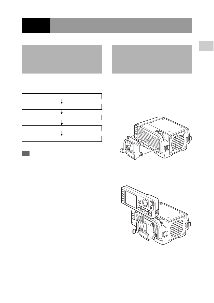
Mount Control Panel
Attach the supplied CP bracket to the unit, and
connect the unit and the control panel with the
control panel cable.
1 Attach the supplied CP bracket to the
right side of the unit.
2 Slide the control panel into the CP
bracket.
Chapter 2 Preparation
Work Flow / Mount Control Panel
15
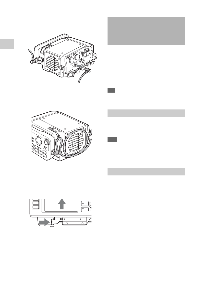
3 Use the supplied control panel cable to
connect the unit and the control panel.
Connect Power
Chapter 2 Preparation
4 Use the cable clamp as shown, to fix the
cable.
To remove the control panel
Grasp the underside of the CP bracket and push it
in the B direction to release the lock. Then slide
the control panel out.
The SR-R1 can be powered either from a battery
pack or AC power.
For safety, do not use any AC adapter or battery
pack other than the Sony products specified
below.
• AC adapter: AC-DN10, AC-DN2B
• Lithium ion battery pack: BP-GL95
Tip
To use the battery pack, the Battery Adapter BKP-L551
(sold separately) is required.
Using AC Power
Use the DC power cable (sold separately) to
connect the AC adapter AC-DN10/DN2B to the
DC IN connector on the SR-R1.
Note
When connecting the output of a battery to the DC IN
connector, access the SYSTEM Setup menu and set the
BATTERY >DC IN TYPE option to other than “AC
Adapter.” (see page 83)
Using the Battery Pack
Before using the battery pack, charge it fully with
the dedicated battery charger.
For detailed information on charging, refer to the
documentation of the battery charger.
WARNING
Batteries shall not be exposed to excessive heat
such as sunshine, fire or the like.
CAUTION
Danger of explosion if battery is incorrectly
replaced.
Replace only with the same or equivalent type
recommended by the manufacturer.
When you dispose of the battery, you must obey
the law in the relative area or country.
AVERTISSEMENT
N’exposez pas les batteries à une chaleur
excessive, au soleil ou près d’un feu par exemple.
16
Connect Power
ATTENTION
Il y a danger d’explosion s’il y a remplacement
incorrect de la batterie. Remplacer uniquement
avec une batterie du même type ou d’un type
équivalent recommandé par le constructeur.
Lorsque vous mettez la batterie au rebut, vous
devez respecter la législation en vigueur dans le
pays ou la région où vous vous trouvez.
WARNUNG
Akkus dürfen keinesfalls übermäßiger
Wärmeeinwirkung ausgesetzt werden, wie z.B.
Sonneneinstrahlung, Feuer o. ä.
VORSICHT
Explosionsgefahr bei Verwendung falscher
Batterien. Batterien nur durch den vom Hersteller
empfohlenen oder einen gleichwertigen Typ
ersetzen.
Wenn Sie die Batterie entsorgen, müssen Sie die
Gesetze der jeweiligen Region und des jeweiligen
Landes befolgen.
Battery pack usage precautions
• If the battery pack is charged immediately after
use while still warm, a full charge may not be
achieved.
• If not using the unit for an extended period,
detach the battery pack.
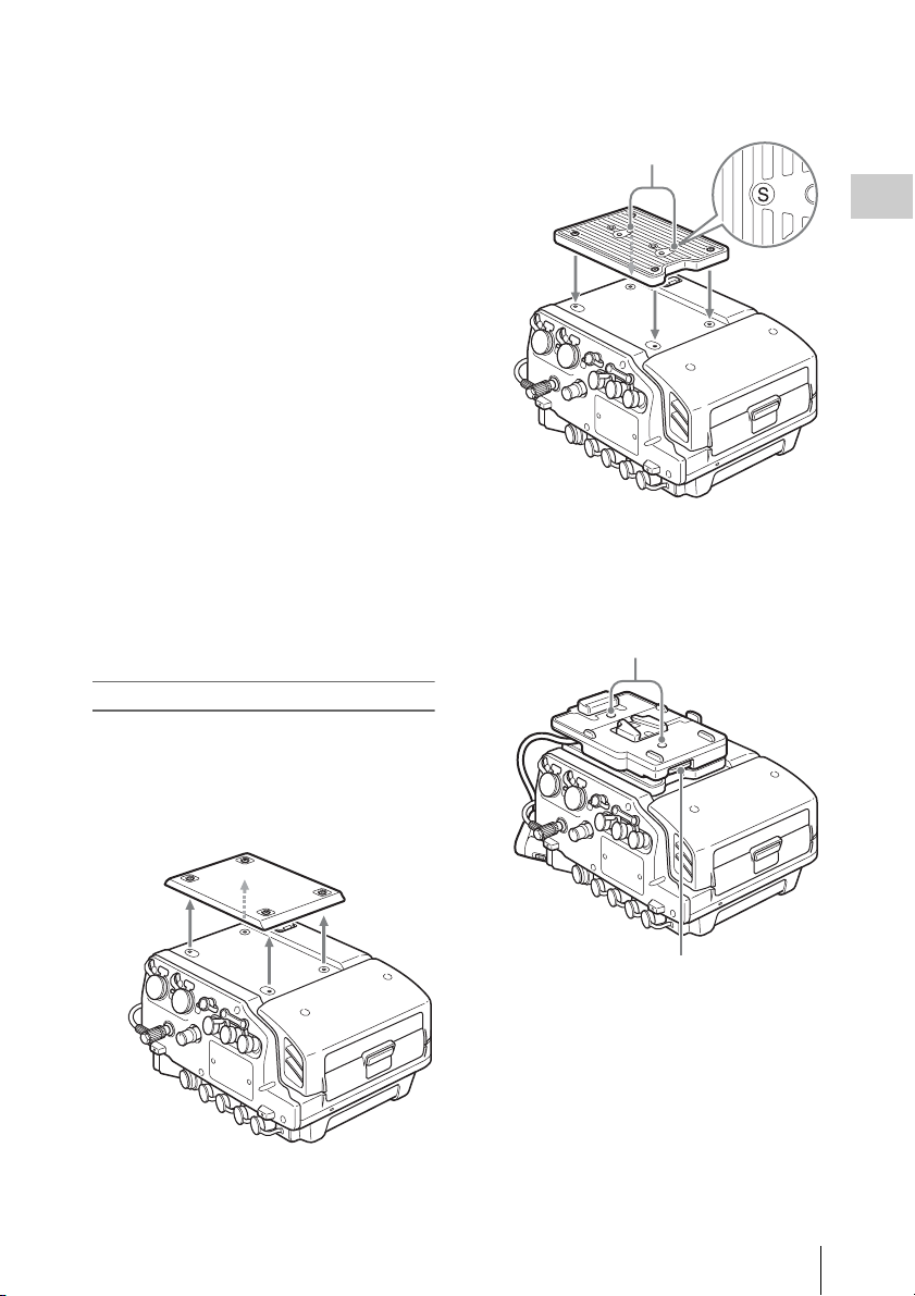
Attaching the battery pack
Use the BKP spacer supplied with the unit and the
separately available BKP-L551 to attach the
battery pack to the top of the unit.
2 Attach the supplied BKP spacer.
The S symbol must face up.
S symbols
Chapter 2 Preparation
3 Attach the BKP-L551 to the screw
threads marked with the S symbol and
connect the power cable to the DC IN
connector.
BKP-L551 fastening L screws
1 Remove the top cover of the unit.
BKP-L551 fastening L wrench
Connect Power
17
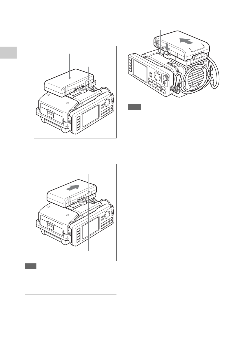
4 Align the line on the side of the battery
pack with the line on the unit and place
the battery pack on the rear section of
the unit.
1 Battery pack
Chapter 2 Preparation
2 Main unit/battery
pack line
5 Push the battery pack down and slide it
in the arrow direction marked
“LOCK.”
1 “LOCK” arrow
Lock release button
Notes
• Never remove the battery pack while a recording is in
progress (tally indicator is lit in red).
• Always turn power to the unit off before removing the
battery pack.
2 Line on main unit
Note
If the battery pack is attached incorrectly, the connectors
may be damaged.
Removing the battery pack
While power to the unit is switched off, hold
down the lock release button and push the battery
pack off.
Connect Power
18

Connect HD SDI Compliant Equipment
Connect equipment with an HD SDI interface to the HD SDI IN (MON) (HD SDI signal input) connector
A/B and HD SDI OUT (HD SDI output) connector A/B of the SR-R1.
Tip
HD SDI input/output settings can be made from the SYSTEM Setup menu, under FORMAT > 3G/DUAL. (see page 79)
Representative connection examples are shown below.
Connecting a Camera/Camcorder
Using the HDW-F900R or similar to record a 4:2:2 signal
SR-R1
HD SDI OUT
HD SDI IN A
HDW-F900R HD Camcorder
Using the HDC1500R to record an RGB 4:4:4 or 4:2:2 50p/59p signal
SR-R1
Chapter 2 Preparation
LINK A/B OUT
HDC1500R Multi-Format Camera System
HD SDI IN A
HD SDI IN B
Connect HD SDI Compliant Equipment
19
Recording the output from two cameras as a 4:2:2 DUAL STREAM (3D)
Reference signal
Chapter 2 Preparation
HDW-F900R HD Camcorder
HDW-F900R HD Camcorder
Connecting an HD Monitor
GENLOCK IN
LINK A OUT
GENLOCK IN
HD SDI OUT
SR-R1
HD SDI IN A
HD SDI IN B
Note
The two cameras must be
synchronized.
HD monitor
Connect HD SDI Compliant Equipment
20
SR-R1
HD video input
HD SDI
HD SDI OUT A
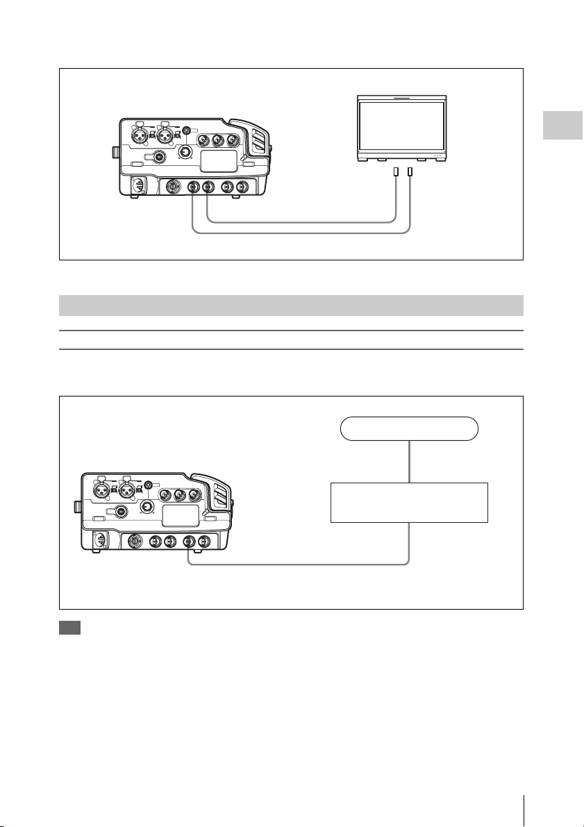
Connecting a RGB4:4:4 and 1080 50p/60p (Dual Link) compatible HD monitor
BVM-E250 HD Monitor
SR-R1
LINK B IN LINK A IN
HD SDI OUT B
HD SDI OUT A
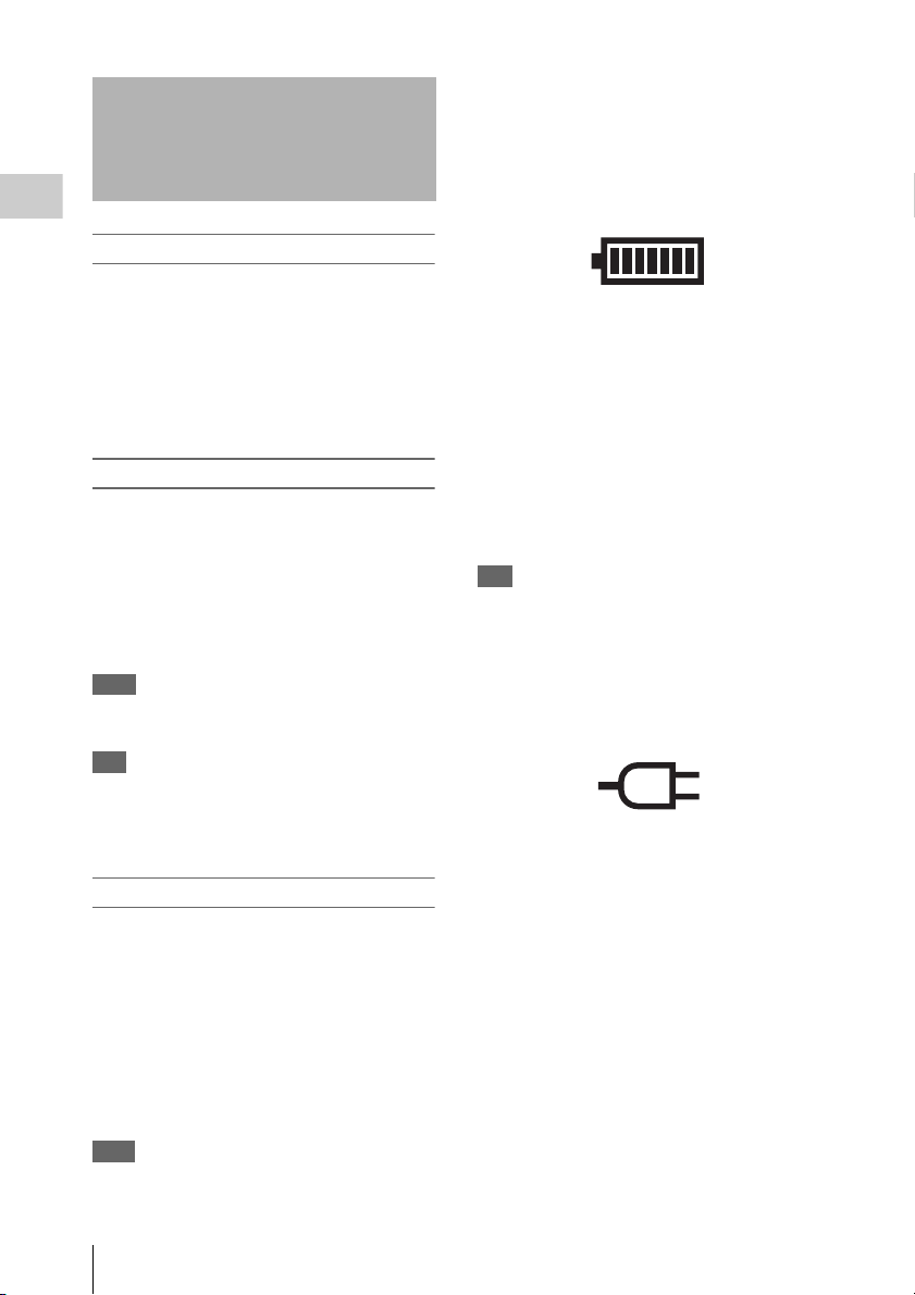
About the Reference Sync Signal
External synchronization required
If external synchronization is required, connect an HD SDI signal synchronized to the reference signal.
Recording/playback with synchronized camera, switcher, signal generator etc.
Reference signal
Chapter 2 Preparation
SR-R1
REF IN, GENLOCK IN
HD SDI IN A/B
(A only, or A/B)
Tip
If no external synchronization source is available, internal sync will be used.
Connect HD SDI Compliant Equipment
Camera, switcher, signal
generator etc.
HD SDI OUT A/B
(A only, or A/B)
21
Turn Power On
• The voltage shown is the actual voltage used by the
unit (this may be lower than the input voltage and the
DC IN connector).
When a battery pack is selected
The battery symbol is shown.
Chapter 2 Preparation
To power up the unit
1 When using the AC adapter, turn
power to the AC adapter on.
2 Press the power switch on the SR-R1 on
the ? side.
Power comes on and the POWER indicator
lights up in green.
To power down the unit
1 Press the power switch on the SR-R1 on
the 1 side.
Power is turned off and the POWER
indicator goes out.
2 When using the AC adapter, turn
power to the AC adapter off.
Note
To prevent the risk of data corruption, do not interrupt
the DC IN power supply while the SR-R1 is turned on.
Tip
If power is turned off while an SRMemory card is
mounted, the unit will not power down immediately, to
protect the data on the card. The SRMemory card will be
unmounted first, and then the unit powers down.
16.5V
• When fully charged, all seven segments are lit.
As the battery pack discharges, the segments go
out from left to right.
• When the battery pack is almost exhausted
(NEAR END), the voltage indication and the
tally indicator start to flash, and an intermittent
warning tone sounds in the earphones.
• When the battery pack is completely exhausted
(END), the corresponding warning indication
lights, the tally indicator starts to flash at a
higher rate, and the earphones warning tone
sounds continuously.
Tip
The DCIN TYPE option in the SYSTEM Setup menu
allows you to set the battery voltages which trigger the
NEAR END and END warnings. (see page 83)
When AC power is selected
The connector symbol is shown.
16.5V
Checking the power/voltage
The indication at the bottom left of the control
panel display serves to verify the battery status or
the voltage of the external power supply.
However, this indication is not based on the
actual connection condition but on the setting
made under SYSTEM Setup > BATTERY >
DCIN TYPE. (see page 83)
Set DCIN TYPE to match the pow er supply being
used.
Tips
• When signal format and SR Motion are shown, the
indication appears at bottom right. (see page 14)
Turn Power On
22
Insert SRMemory Card
Supported SRMemory cards
The SR-R1 can use the following types of
SRMemory cards.
For 59.94i
SRMemory card SR-Lite SR-SQ SR-HQ
SR-256S15/256S55 114 60 32
SR-512S25/512S55 229 120 64
SR-1TS25 458 241 128
Unit: minutes (approx.)
For 50i
SRMemory card SR-Lite SR-SQ SR-HQ
SR-256S15/256S55 137 72 38
SR-512S25/512S55 274 145 76
SR-1TS25 550 290 153
Unit: minutes (approx.)
For 23.98P
SRMemory card SR-Lite SR-SQ SR-HQ
SR-256S15/256S55 143 75 40
SR-512S25/512S55 286 151 80
SR-1TS25 573 302 160
Unit: minutes (approx.)
1) Recording times will differ depending on equipment
and shooting conditions.
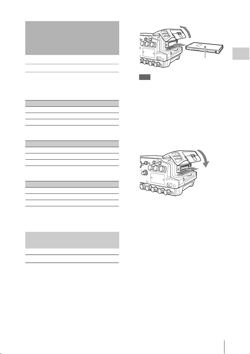
Inserting and Removing the SRMemory Card
To insert the SRMemory card
1 Press the lid open/close button to open
the lid of the SRMemory card slot and
insert the SRMemory card.
Take care to insert the SRMemory card with
the correct orientation.
SRMemory card
Tips
• If the LID LOCK indicator is lit in orange,
showing that the lid is locked, press the EJECT
button on the control panel to unmount the card
first, and then open the lid.
• If power was turned off with the lid in the locked
state, turn power on again and then press the
EJECT button on the control panel to unmount
the card.
2 Push the SRMemory card all the way in
and close the lid.
The SRMemory card is mounted, and the
LID LOCK indicator lights up in orange.
Verify that no error message is shown on the
control panel display.
If “XXX: SALVAGE DETECT” is shown on the
display
This indicates that the previous recording did not
complete normally.
For information on what to do in this case, see
“Salvaging SRMemory cards for which recording
did not complete properly” (page 92) in the
“Troubleshooting” section.
Chapter 2 Preparation
Insert SRMemory Card
23

To remove the SRMemory card
1 Press the EJECT button on the control
panel while power to the unit is on.
The files in the SRMemory card are closed
automatically, the SRMemory card is
Chapter 2 Preparation
unmounted, and the lock of the lid is
released.
During the unmount procedure, the indicator
of the EJECT button on the control panel is
lit.
2 Press the lid open/close button to open
the lid.
3 Press the EJECT button on the right
side of the slot to remove the
SRMemory card.
Pressing this button causes the SRMemory
card to pop out.
Formatting an SRMemory Card (File System Format )
SRMemory cards are sold already formatted, so
you can use a newly purchased SRMemory card
right away.
To format an SRMemory card on which data were
recorded, proceed as follows.
Note
Formatting will erase all files and data on the SRMemory
card.
For details on menu operation, see “Basic Menu
Operations” (page 25).
1 Press the SYSTEM button.
The SYSTEM Setup menu appears.
2 Select and confirm “SRMEMORY” t
select and confirm “FS FORMAT” t
move the cursor to [OK] and confirm.
The file system formatting process starts.
When the process is finished, the indication
“Completed” is shown.
3 Return to the HOME screen. (see
page 26)
Write-protecting the card
In order to prevent inadvertent erasure of
recorded content, you can slide the write protect
switch to “WP.”
Write protect switch Slide
fully to the right.
When the card is inserted in the SR-R1 in this
condition, the indication “REC INHI” appears,
and recording is not possible.
To re-enable recording on this card, return the
write protect switch to the original condition.
Insert SRMemory Card
24
Chapter 3 Basic Menu Operations
The menu system of the SR-R1 consists of the
following four menus.
Menu Overview
TC Setup Serves for making time code
settings.
VIDEO Setup Serves for making video signal
related settings.
AUDIO Setup Serves for making audio signal
related settings.
SYSTEM Setup Serves for making system
settings.
For details on menu items, see “Menu Details”
(page 69).
The menu is operated with the control panel.
Buttons Used for Menu Operations
HOME button SELECT/ENTER dial
BACK button
TC Setup
TIMER SEL
HOME
TC
VIDEO
AUDIO
SYSTEM
TIMER RESET
TIMER PRESET
TCR SEL
TCG MODE
REGEN SRC
RUN MODE
TCG SET
OTHERS
CHAR
TC
LTC
PRST
INT L
R RUN
SR-R1
TCR
Menu selection buttons
KEY INHI
OFF ON
LIGHT
OFF ON
EJECT STOP PLAY
FUNC
00:00:00:00STOP
ADJUST
xZzB
REW F FWD PAUSE
mXM
SELECT/ENTER
REC
BACK
Serve for Selecting a Menu
Selecting a menu
Press the respective menu selection button.
TC: Brings up the TC Setup menu.
VIDEO: Brings up the VIDEO Setup menu.
AUDIO: Brings up the AUDIO Setup menu.
SYSTEM: Brings up the SYSTEM Setup menu.
Selecting and making settings within a
menu
Example: TC Setup menu
1 Rotate the SELECT/ENTER dial to
move the cursor to the target item, and
press the SELECT/ENTER dial.
TC Setup
TIMER SEL
TIMER RESET
TIMER PRESET
TCR SEL
TCG MODE
REGEN SRC
RUN MODE
TCG SET
OTHERS
CHAR
SR-R1
A submenu for the selected item appears, and
the cursor moves to the submenu.
If the selected item is a command, the
command is executed.
Cursor
TC
LTC
PRST
INT L
R RUN
TCR
00:00:00:00STOP
Chapter 3 Basic Menu Operations
25
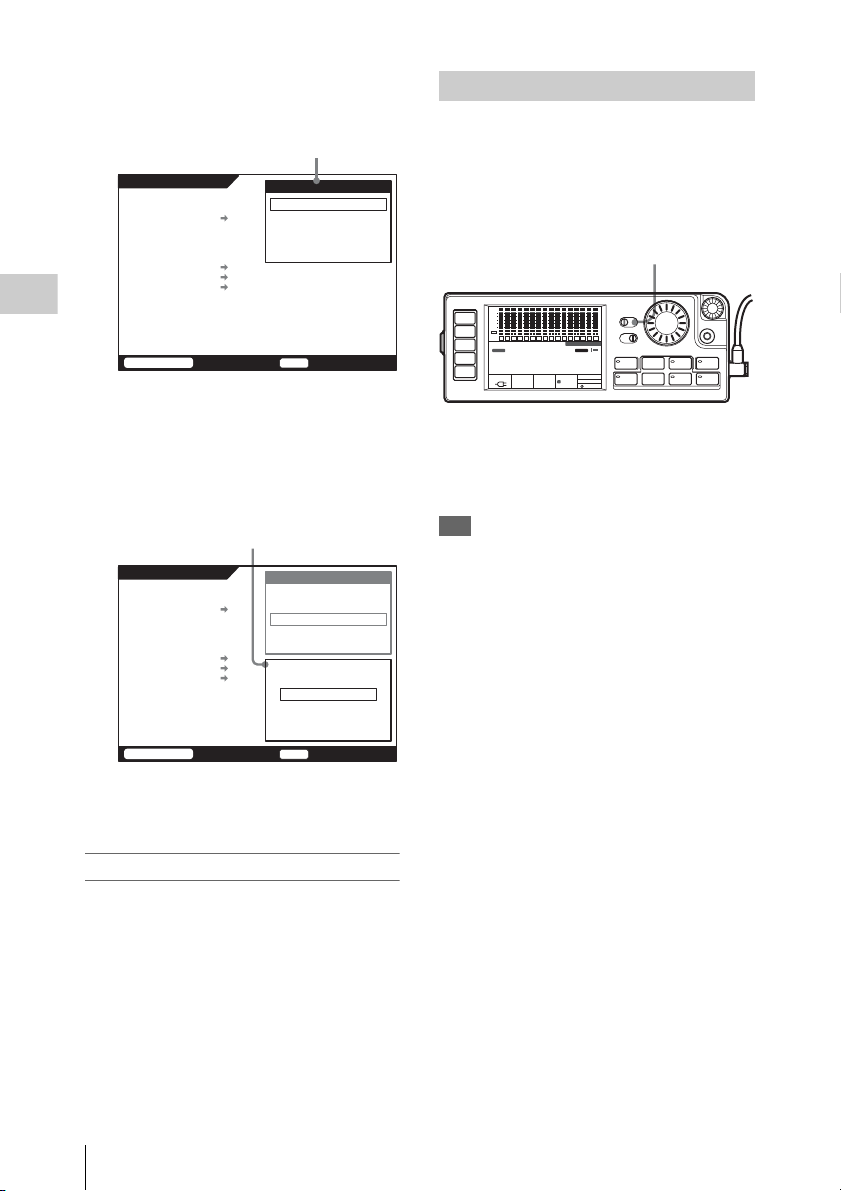
2 Rotate the SELECT/ENTER dial to
move the cursor to the target item, and
press the SELECT/ENTER dial.
Submenu window
TC Setup
TIMER SEL
TIMER RESET
TIMER PRESET
TCR SEL
TCG MODE
REGEN SRC
RUN MODE
TCG SET
OTHERS
CHAR
TC
LTC
PRST
INT L
R RUN
DF/NDF
UBG SRC
12H/24H
Chapter 3 Basic Menu Operations
SR-R1
A setting window appears, and the cursor
moves to the setting window.
3 Rotate the SELECT/ENTER dial to
select the desired setting, and press the
SELECT/ENTER dial to accept the
setting.
Setting window
TC Setup
TIMER SEL
TIMER RESET
TIMER PRESET
TCR SEL
TCG MODE
REGEN SRC
RUN MODE
TCG SET
OTHERS
CHAR
TC
LTC
PRST
INT L
R RUN
DF/NDF
UBG SRC
12H/24H
TCG Setting(Main)
TCR
00:00:00:00STOP
TCG Setting(Main)
12H/24H MODE
+/-12H
24H
DF
TCG
24H
DF
TCG
24H
Locking the Controls
To prevent operation errors or an inadvertent
change in settings, the controls of the unit can be
locked.
Access the SYSTEM Setup menu and set KEY
INHI to “ALL” (see page 80), and then slide the
KEY INHI switch to ON.
KEY INHI switch
SDI
SDI
SDI
SDI
SDI
SDI
SDI
SDI
SDI
SDI
SDI
SDI
SDI
SDI
SDI
dB
0
-10
HOME
-20
-30
-60
EMP
EMP
EMP
EMP
EMP
EMP
EE
TC
LR
LR
LR
LR
LR
LR
1
2
3
4
5
VIDEO
AUDIO
SYSTEM
6
STOP
TCG
00H 00M00 S 00F
16.5V
REMAIN
10min
ON: All controls of the unit are inactive.
SYSTEM: During recording, the STOP and PAUSE
keys are active, and all other controls are
inactive. (When not recording, all controls of the
unit are inactive.)
Tip
When KEY INHI in the SYSTEM Setup menu is
set to “Map”, the “KEYMAP” settings apply. (see
page 80)
SDI
KEY INHI
10
59.94I
EMP
LR
1920x1080
M
OFF ON
EMP
EMP
EMP
EMP
EMP
EMP
L R
11
4:2:2
LIGHT
L R
L R
L R
LR
LR
12
13
14
15
16
OFF ON
SR-R1
KEY
INHI
RECINHI
EJECT STOP PLAY
LOCAL
FUNC
EE
21:46
EMP
EMP
EMP
LR
LR
L R
7
8
9
ENCODE
SR-SQ
12bit
ADJUST
xZzB
REW F FWD PAUSE
mXM
SELECT/ENTER
REC
BACK
SR-R1
To return to an upper level
Press the BACK button.
To return to the HOME screen
Press the HOME button or press the BACK
button repeatedly.
26
TCR
00:00:00:00STOP
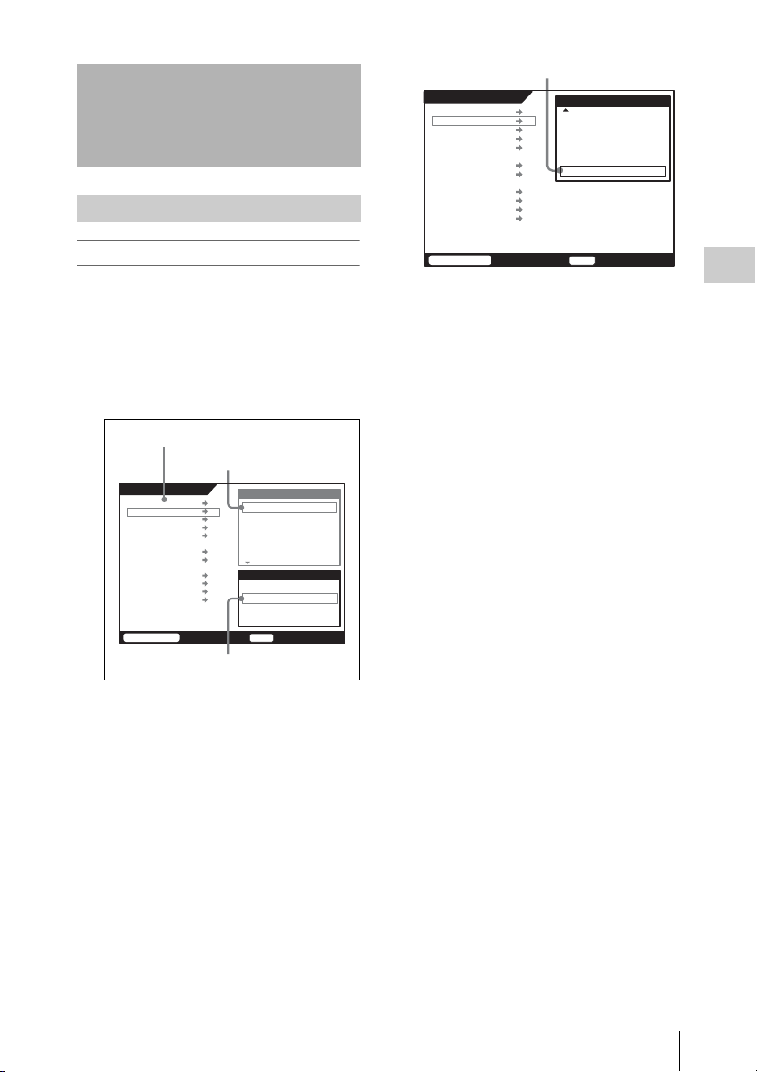
Signal Format Settings
Selecting the Signal Format
SYSTEM Setup
FILE LIST
SIGNAL FORMAT
TEST SG
LCD
KEYMAP
KEYINHI MAP
REMOTE/LOCAL
SERVO
REC INHI OFF
EDIT
POWER
BATTERY
OTHERS
SET
Signal Format
ENCODE
3D MODE
SELECT FPS
FPS FORMAT
HD SDI
[SET]
SR-SQ
OFF
OFF
DEF
1.5G
Making “SIGNAL FORMAT” settings
1 Press the SYSTEM button.
The SYSTEM Setup menu appears.
2 1 Select "SIGNAL FORMAT", and
confirm t2 select "PIXEL" , and
confirm t3 select the format to use,
and confirm.
1 SIGNAL FORMAT
2 PIXEL
SYSTEM Setup
FILE LIST
SIGNAL FORMAT
TEST SG
LCD
KEYMAP
KEYINHI MAP
REMOTE/LOCAL
SERVO
REC INHI OFF
EDIT
POWER
BATTERY
OTHERS
SR-R1
Signal Format
PIXEL
FRAME
SIGNAL
ENCODE
3D MODE
SELECT FPS
PIXEL
1280x720P
1920x1080I
1920x1080PsF/P
TCR
00:00:00:00STOP
1920x1080I
29.97
422
SR-SQ
OFF
OFF
3 Signal format
Return to submenu window.
3 Make settings for FRAME, SIGNAL,
ENCODE, and 3DMODE in the same
way.
SR-R1
TCR
00:00:00:00STOP
The settings complete message is shown, and
the HOME screen appears again.
Chapter 3 Basic Menu Operations
4 Set SELECT FPS, FPS FORMAT, and
HD SDI as necessary.
5 After settings are complete, select SET.
Signal Format Settings
27
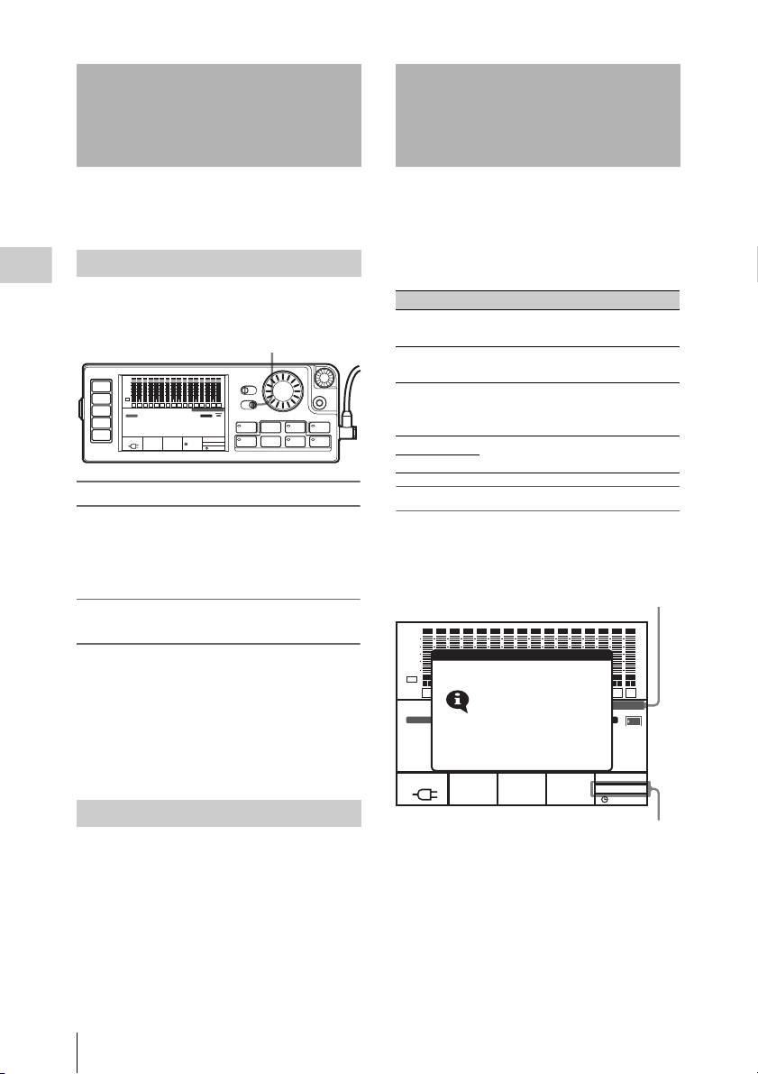
Display Settings
Power Save Settings
You can make settings for backlight use in dark
locations, screen saver, etc.
Using the Backlight
Chapter 3 Basic Menu Operations
Setting the LIGHT switch to ON turns the
backlight on.
LIGHT switch
SDI
SDI
SDI
SDI
SDI
SDI
SDI
SDI
SDI
SDI
SDI
SDI
SDI
SDI
SDI
dB
0
-10
HOME
-20
-30
-60
EMP
EE
TC
LR
1
VIDEO
TCG
AUDIO
00H 00M00 S 00F
SYSTEM
16.5V
EMP
EMP
EMP
EMP
EMP
LR
LR
LR
LR
LR
2
3
4
5
6
STOP
REMAIN
10min
SDI
KEY INHI
LR
10
59.94I
EMP
1920x1080
M
OFF ON
EMP
EMP
EMP
EMP
EMP
EMP
L R
11
4:2:2
LIGHT
L R
L R
L R
LR
LR
12
13
14
15
16
OFF ON
SR-R1
KEY
INHI
RECINHI
EJECT STOP PLAY
FUNC
xZzB
REW F FWD PAUSE
mXM
LOCAL
EE
21:46
EMP
EMP
EMP
LR
LR
L R
7
8
9
ENCODE
SR-SQ
12bit
Adjusting the backlight brightness
Access the SYSTEM Setup menu and select LCD
> BRIGHT (see page 80). The Backlight
Brightness window appears, letting you adjust the
setting.
Turning the backlight off after a period of
inactivity
Access the SYSTEM Setup and select LCD >
LIGHT OFF (see page 80). The Backlight Off
Timer window appears, letting you adjust the
backlight activation duration. The setting range is
5 seconds to 5 minutes. To disable automatic
backlight deactivation, select “Disable.”
Default setting: Disable
Using the Screen Saver
Access the SYSTEM Setup menu and select LCD
>SAVER (see page 80). The Screen Saver
window appears, letting you adjust the wait
interval until the screen saver is activated. The
setting range is 1 minute to 1 hour. To disable the
screen saver, select “Disable.”
Default setting: Disable
The SR-R1 can be set to reduce power
consumption and thereby extend battery life.
Available settings are described below.
Access the SYSTEM Setup menu and select
POWER (see page 82) to make a setting.
Item Setting
MODE: Conserves power by limiting the
output signal.
SAVE
MODE
SELECT/ENTER
BACK
ADJUST
REC
SDI OUT Conserves power by disabling
Selects whether power save mode is
used or not.
signal output from HD SDI OUT
connectors A/B.
LED Conserves power by reducing the
TAL LY
indicator brightness.
Operation in power save mode
When SAVE MODE is set to SAVE, thereby
activating power save mode, the following popup
appears on the display.
Power Save Mode1: *SR-R1
Power Save Mode1: **SR-R1
SDI
SDI
SDI
SDI
SDI
SDI
SDI
SDI
SDI
SDI
SDI
SDI
SDI
SDI
SDI
13
EMP
L R
EMP
L R
14
SR-R1
PB SAVE
INHI
21:46
SDI
EMP
EMP
L R
L R
15
16
RECINHI
F
LOCAL
XX SAVE
dB
0
-10
-20
-30
-60
EMP
EMP
EE
L R
L R
1
TCG
00H00M00S00
16.5V
INFORMATION
EMP
EMP
EMP
EMP
EMP
EMP
5
L R
L R
6
7
DF
ENCODE
SR-R1
10bit
EMP
L R
L R
8
9
EXT-LK KEY
L R
L R
L R
2
3
4
POWER SAVE
MODE1
PLAY LOCK
LTC
INTRP
Entering Power Save Mode1
LTC VITC AU
REMAIN
- - -
EMP
EMP
L R
L R
10
11
1920x1080
59.94I
4:2:2
EMP
L R
12
Setting options are Power Save Mode 1 and
Power Save Mode 2 which operate as follows.
Power Save Mode 1: Only E-E image of SDI IN
connector is output.
Power Save Mode 2: No output.
Display Settings / Power Save Settings
28
When SRMemory card is inserted
Standby off
r after 30 seconds
Power Save Mode 1
r after 30 seconds
Power Save Mode 2
r When Rec/Play button is pressed...
Power save mode is canceled.
When no SRMemory card is inserted
SAVE selected
r after 30 seconds
Power Save Mode 1
r after 30 seconds
Power Save Mode 2
r When REC button is pressed...
Power save mode is canceled.
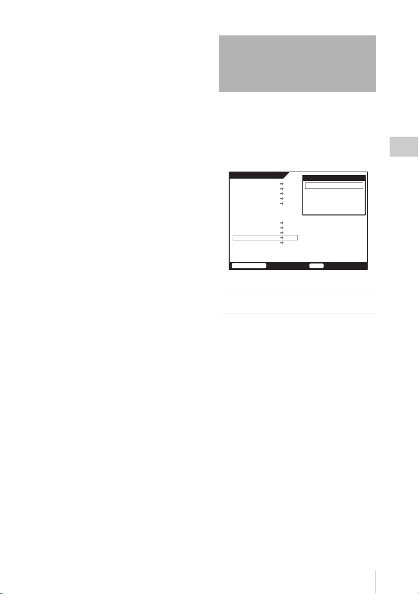
Storing and Recalling Setup Data
In the SETUP menu of the System menu, you can
save the setup data to a “Memory Stick” and read
the setup data from a “Memory Stick.” You can
also add a comment to the setup information and
restore the setup information to the factory
default state.
SYSTEM Setup
FILE LIST
SIGNAL FORMAT
TEST SG
LCD
KEYMAP
KEYINHI MAP
REMOTE/LOCAL LCC
REC INHI ON
EDIT
POWER
BATTERY
SETUP
OTHERS
SETUP Save/Lode
COMMENT
SAVE
LOAD
RESET
Chapter 3 Basic Menu Operations
SR-R1
TCR
00:00:00:00STOP
To add a comment to the Setup data
(COMMENT menu)
You can edit the comment to be added when the
Setup data of the selected device is saved to a
“Memory Stick.”
1 In the Setup Save/Load window, select
and confirm “COMMENT.”
The Edit Comment screen appears.
2 Select characters and symbols on the
displayed screen to enter a comment in
the COMMENT field.
Up to 15 characters (including symbols) can
be entered in the COMMENT field.
Storing and Recalling Setup Data
29

Edit Comment
< COMMENT : max 15 characters >
Untitled
B
A
CDEFGHIJKLM
N
O
PQRSTUVWXYZ
a
b
cdefghijklm
n
o
pqrstuvwxyz
0
1
23456789[](
)
<
>@+-*=!?:;|
$
#
%&,."\^_'/~
`
{
}HD1D2CAM
SPC
BS
SR-R1
TCG
3 Once you have finished editing the
Chapter 3 Basic Menu Operations
comment, save the setup data to the
“Memory Stick.”
See “To save the setup data (SAVE menu)”
(page 30).
To save the setup data (SAVE menu)
You can save the setup data to a “Memory Stick.”
1 In the Setup Save/Load window, select
and confirm “SAVE.”
The Setup Save screen appears.
2 Select and confirm the number (01 to
06) of the bank to which to save the
setup data.
A message for confirming the bank number
of the save destination appears.
3 Confirm the bank number, select [OK],
and then press the SELECT/ENTER
dial while holding down the FUNC
button.
Setup Save
< Untitled >
Selected Save Position
01 ---------------- ----/--/-- --:--
02 ---------------- ----/--/-- --:--
03 ---------------- ----/--/-- --:--
04 ---------------- ----/--/-- --:--
05 ---------------- ----/--/-- --:--
06 ---------------- ----/--/-- --:--
Save to 02 as < Untitled > ?
Press [FUNC]+[ENTER] to Save.
CANCEL
SR-R1
The setup data is saved to the “Memory
Stick” under the comment name added in the
COMMENT menu.
Tip
If you want to cancel the operation, select and
confirm [CANCEL] to return to the Setup Save
screen.
OK
TCG
When saving of the setup data is finished,
“Completed” appears at the bottom of the
Setup Save screen.
Tip
The setup data is saved to the “/MSSONY/PRO/
SRMASTER/R1/” directory.
CLR
END
00:00:00:00STOP
To read the setup data from a
“Memory Stick” and load it into the unit
(LOAD menu)
You can read the setup data from a
“Memory Stick” and load it into the SR-R1.
1 In the Setup Save/Load window, select
and confirm “LOAD.”
The Setup Save screen appears.
2 Select and confirm the number (01 to
06) of the bank from which to read the
setup data.
A message for confirming the bank number
of the read destination appears.
3 Confirm the bank number, select [OK],
and then press the SELECT/ENTER
dial while holding down the FUNC
button.
Setup Load
Load Setup Data
Select Load Data
01 ---------------- --.------- --/--
02 Untitled 00.03-3002 11/31
03 ---------------- --.------- --/--
04 ---------------- --.------- --/--
05 ---------------- --.------- --/--
06 ---------------- --.------- --/--
Load Setup Data 02 ?
Press [FUNC]+[ENTER] to Load.
CANCEL
SR-R1
Reading starts, and the setup data is loaded
into the SR-R1.
Tip
00:00:00:00STOP
If you want to cancel the operation, select and
confirm [CANCEL] to return to the Setup Save
screen.
The window of the format recorded in the
setup data appears, and then the SR-R1
restarts after several seconds.
OK
TCG
00:00:00:00STOP
Storing and Recalling Setup Data
30
 Loading...