

Page 1

HD Color
C-289-100-12 (1)
Video Camera
Operating Instructions
Before operating the unit, please read this manual thoroughly
and retain it for future reference.
SRG-360SHE
© 2016 Sony Corporation
Page 2

Table of Contents
Overview
Features .......................................................5
How to Use This Operating Instructions... 6
Camera and Supplied Accessories ...........6
Location and Functions of Parts and
Controls.................................................8
Camera ....................................................8
Infrared Remote Commander ...................10
System Configuration...............................12
Operating the Camera Via a Network........12
Operating a Camera Using the Remote
Controller ......................................13
Operating Multiple Cameras Using Multiple
Remote Controllers.........................14
Precautions for Preventing Access to the
Camera by an Unintended Third
Party.....................................................15
Installation and Connection
Installing the Camera................................16
Installing the Camera on a Desk ...............16
Attaching the Camera to a Tripod .............16
Installing the Camera Using the M3 Fixing
Screw Holes...................................16
Installing the unit on the ceiling................16
Connections...............................................19
Connecting the power supply ...................19
Connecting to the PoE+ (Power over Ethernet
plus) power supply system...............20
RS-422 connection with IP remote controller
RM-IP10 .......................................20
LAN connection with IP remote controller
RM-IP10 .......................................21
Connecting a Video Monitor, etc., Equipped
with HDMI Input Connector............21
Connecting with monitors with SDI input
connectors .....................................22
Connection with commercially-available
microphones etc. ............................22
Adjusting and Setting with Menus
About On-Screen Menus ..........................23
Main Menu.............................................23
Setting Menus.........................................23
Control Button Display Section ................23
EXPOSURE Menu......................................24
WHITE BALANCE Menu............................25
PICTURE Menu ..........................................26
PAN TILT ZOOM Menu..............................27
SYSTEM Menu ...........................................28
STATUS Menu ...........................................28
Operation Using the Supplied
Infrared Remote Commander
Before Operating.......................................29
Turning on the Power ...............................29
Pan/Tilt and Zoom Operation ...................30
Panning and Tilting.................................30
Zooming ................................................31
Operating Multiple Cameras with the Infrared
Remote Commander .......................31
Adjusting the Camera ...............................31
Focusing on a Subject..............................31
Shooting with Back Lighting....................31
Presetting Feature.....................................32
PTZ TRACE Feature ..................................33
Recording pan/tilt/zoom operations ..........33
Playing back pan/tilt/zoom operations.......33
Deleting pan/tilt/zoom operations .............33
2
Page 3

Operation Using the Remote
Controller
Preparation ................................................34
Operating a Camera Using the Remote
Controller ............................................35
Operating Multiple Cameras Using Multiple
Remote Controllers ............................35
Pan/Tilt and Zoom Operation ...................35
Panning and Tilting .................................35
Zooming ................................................36
Adjusting the Camera ...............................36
Focusing on a Subject..............................36
Shooting with Back Lighting....................37
Adjusting the White Balance....................37
Presetting Feature.....................................37
Storing Camera Settings ..........................37
PTZ TRACE Feature ..................................39
Recording pan/tilt/zoom operations...........39
Playing back pan/tilt/zoom operations.......39
Deleting pan/tilt/zoom operations .............39
Setting with the Remote Controller
About On-Screen Menus ..........................40
Operating with the Remote Controller.......40
Main Menu.............................................40
Setting Menu ..........................................40
Control Button Display Section ................41
EXPOSURE Menu......................................41
WHITE BALANCE Menu............................42
PICTURE Menu ..........................................43
PAN TILT ZOOM Menu..............................44
SYSTEM Menu ...........................................45
STATUS Menu............................................45
Operating the Camera Via a Network
Accessing the Camera Using the Web
Browser ...............................................46
About Viewers........................................46
Operating the Camera...............................47
Main menu .............................................47
Monitor screen........................................47
Operation panels .....................................48
Pan/Tilt and Zoom Operation ...................49
Controlling via the control panel ..............49
Controlling via the preset position panel.... 50
Controlling using the monitor screen ........50
Setting the Camera Via a Network
Basic Operations of the Administrator
Menu ....................................................51
How to set up the Administrator menu ......51
Configuration of the Administrator
menu .............................................51
System Menu .............................................52
Information Tab......................................52
Installation Tab.......................................52
Initialize Tab ..........................................53
System log Tab.......................................54
Access log Tab .......................................54
Video Menu ................................................54
Picture Tab.............................................54
Video codec Tab .....................................56
Superimpose Tab ....................................57
Day/Night ICR Tab.................................57
Audio Menu................................................58
Audio Tab ..............................................58
Network Menu............................................59
Network Tab ..........................................59
Security Menu............................................61
Administrator and User ...........................61
User Tab ................................................61
Access limit Tab .....................................62
Referer check Tab ...................................62
PTZF control Menu....................................63
PTZF control Tab ...................................63
Preset position Tab..................................64
Streaming Menu ........................................65
Streaming Tab ........................................65
3
Page 4

Appendix
Message List..............................................67
Troubleshooting ........................................68
Menu Configuration ..................................69
Initial value and preset..............................71
Specifications............................................72
Using the VISCA RS-422 connector pin
assignments ...................................74
4
Page 5
Overview
Features
• Supports simultaneous IP image output and HDMI/SDI
output.
• Stereo audio (2ch), which is applicable for microphone/
line input.
Transfers input audio signal to IP/HDMI/SDI
simultaneously.
• The 1/2.8 type Exmor CMOS delivers high-definition
shooting with superior picture quality.
• Adopts wide and dynamic range functions. Creates
images achieving high visibility, even when bright and
dark subjects are incorporated.
• Noise Reduction function delivers clearer images even
in low light environment.
• H.264 High Profile video compression mode (video
codec) achieves high compression rate while keeping
the image quality.
Lessens the network bandwidth load required for image
transferring.
• Supports multi-streaming of IP transfer. Up to 3 codec
modes can be selected.
• Equipped with smooth, wide-range pan/tilt function
and Eflip function. You can install the camera on
ceilings.
• Equipped with 30x optical magnification and F1.6 high
power and luminous zoom lens that achieves highquality image.
• Up to 256 camera positions can be preset.
• Equipped with RS-422 interface, industry standard
VISCA camera protocol with external connection.
• Capable of PTZ interlocking and recording and
replaying the track.
• Pan, Tilt, Zoom, and other camera settings can be set on
the menu display.
• Power can be supplied from the AC power adaptor as
well as via the network cable (PoE+), making installing
easier.
* When power is supplied by PoE+, the available
functions will be limited. For details, refer to
“Connecting to the PoE+ (Power over Ethernet plus)
power supply system” on page 20.
NOTICE TO USERS
© 2014 Sony Corporation. All rights reserved. This
manual or the software described herein, in whole or
in part, may not be reproduced, translated or reduced
to any machine readable form without prior written
approval from Sony Corporation.
SONY CORPORATION PROVIDES NO
WARRANTY WITH REGARD TO THIS
MANUAL, THE SOFTWARE OR OTHER
INFORMATION CONTAINED HEREIN AND
HEREBY EXPRESSLY DISCLAIMS ANY
IMPLIED WARRANTIES OF
MERCHANTABILITY OR FITNESS FOR ANY
PARTICULAR PURPOSE WITH REGARD TO
THIS MANUAL, THE SOFTWARE OR SUCH
OTHER INFORMATION. IN NO EVENT SHALL
SONY CORPORATION BE LIABLE FOR ANY
INCIDENTAL, CONSEQUENTIAL OR SPECIAL
DAMAGES, WHETHER BASED ON TORT,
CONTRACT, OR OTHERWISE, ARISING OUT
OF OR IN CONNECTION WITH THIS MANUAL,
THE SOFTWARE OR OTHER INFORMATION
CONTAINED HEREIN OR THE USE THEREOF.
Sony Corporation reserves the right to make any
modification to this manual or the information
contained herein at any time without notice.
The software described herein may also be governed
by the terms of a separate user license agreement.
• is trademark of Sony Corporation.
• “Exmor” and are trademarks of Sony
Corporation.
• Microsoft, Windows, Internet Explorer and
Microsoft DirectX are registered trademarks of
Microsoft Corporation in the United States and/or
other countries.
• Java Script is a trademark of Sun Microsystems,
Inc. in the United States and other countries.
• Intel Core is a registered trademark of Intel
Corporation or its subsidiaries in the United States
and other countries.
• Adobe, Adobe Reader and Adobe Flash are
trademarks of Adobe Systems Incorporated in the
United States and/or other countries.
• The terms HDMI and HDMI High-Definition
Multimedia Interface, and the HDMI Logo are
trademarks or registered trademarks of HDMI
Licensing LLC in the United States and other
countries.
All other company and product names are trademarks
or registered trademarks of the respective companies
or their respective makers.
5
Page 6
How to Use This
Camera and Supplied
Operating Instructions
This Operating Instruction manual describes how to
operate the HD Color Video Camera using the infrared
remote commander in the package, a PC via a network, or
an optional remote controller.
The Operating Instructions is designed to be read on the
computer display.
This section gives tips on making the most of the
Operating Instructions. Read it before you operate the
camera.
Jumping to a related page
When you read the Operating Instructions on the
computer display, you can click on a sentence to jump to
a related page.
Software display examples
Note that the displays shown in the Operating Instructions
are explanatory examples. Some displays may be
different from the ones that appear in actual use.
The illustrations of the camera and menu display in the
Operating Instructions show the SRG-360SHE as an
example.
Accessories
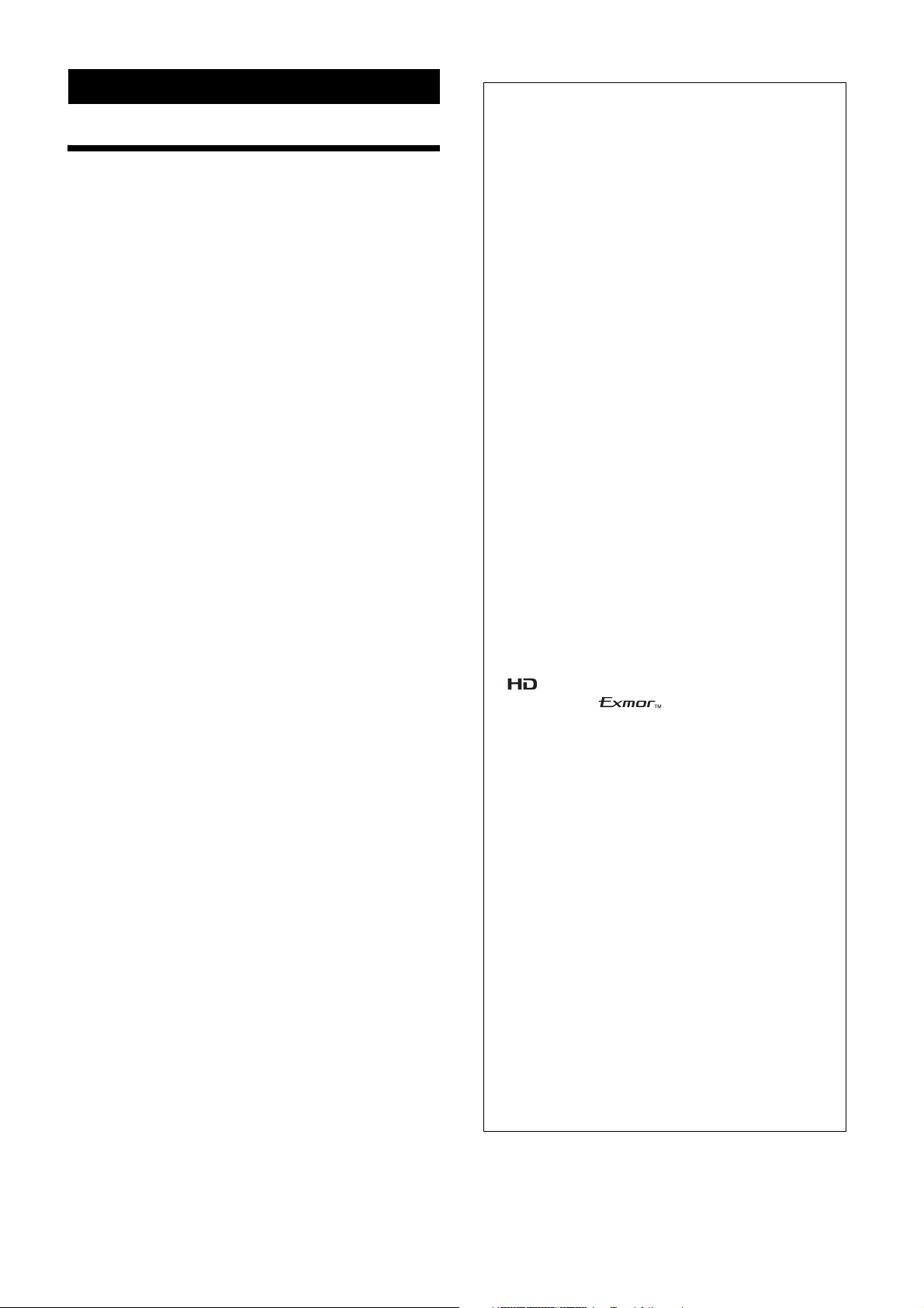
When you unpack, check that all the supplied accessories
are included.
Camera (1)
AC power adaptor (MPA-AC1) (1)
Printing the Operating Instructions
Depending on your system, certain displays or
illustrations in the Operating Instructions, when printed
out, may differ from those that appear on your screen.
Remote Controller
You can operate and set the camera by using the IP
Remote Controller (RM-IP10) (optional accessary).
The IP Remote Controller is described simply as “Remote
Controller” in this manual.
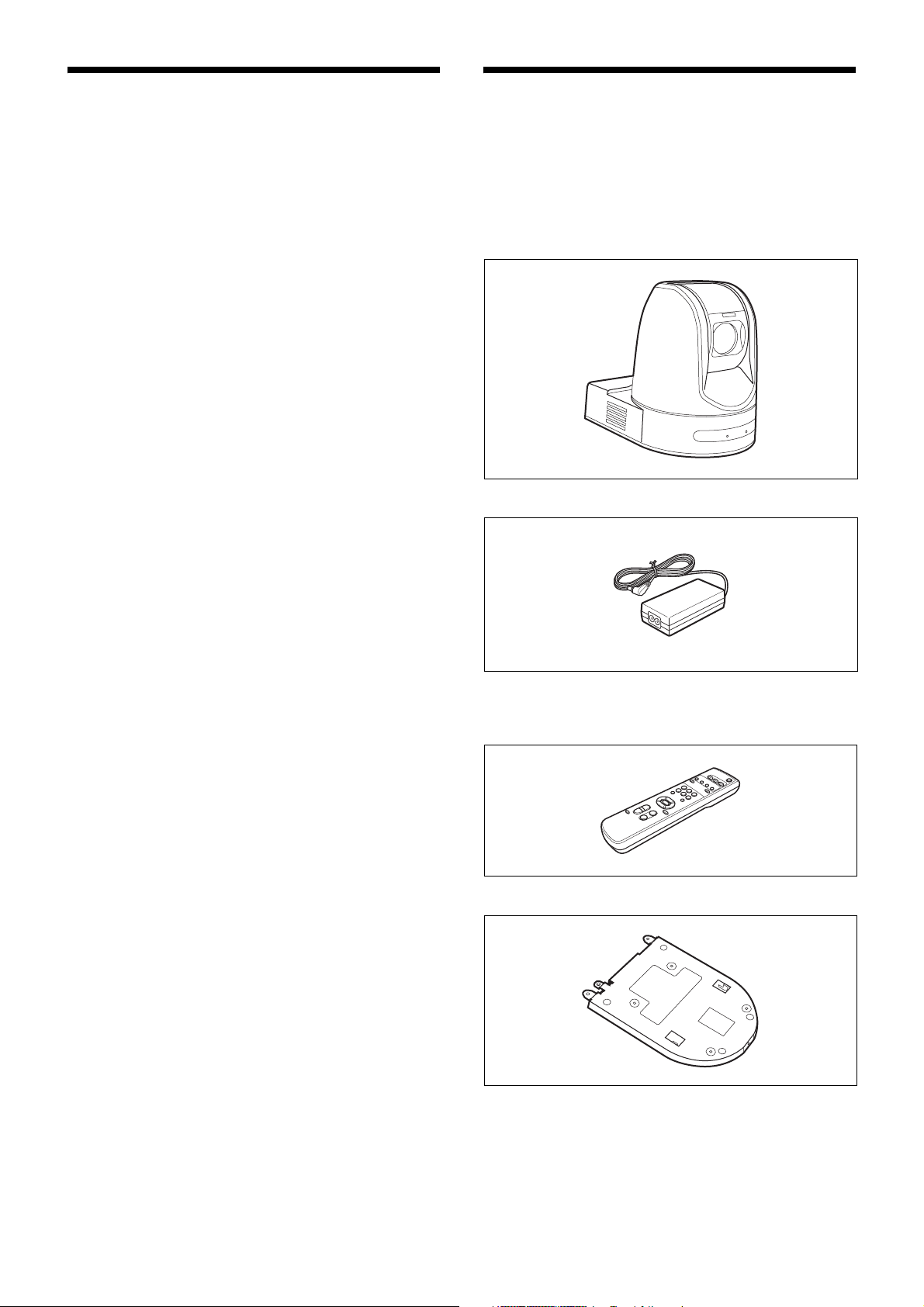
AC power cord (1)
Infrared remote commander (RM-EV100) (1)
Ceiling bracket (A) (1)
6
Page 7
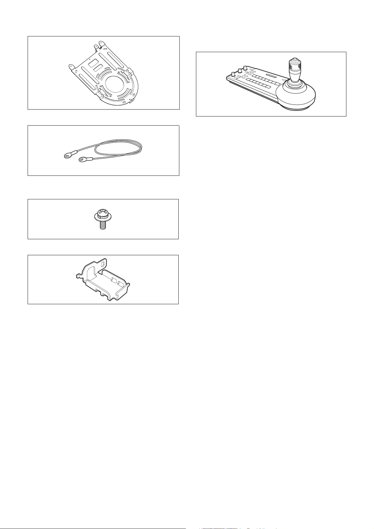
Ceiling bracket (B) (1)
Optional Products
RM-IP10 IP Remote Controller
Wire rope (1)
Screw +M3 × 8 (9)
Screw +M2.6 × 6 black (1)
HDMI cable fixing plate (1)
Operate up to 112 cameras that are compatible with an IP
connection. Up to five RM-IP10 IP remote controllers can
be installed to the same system.
The joystick of the IP remote controller offers
comfortable pan/tilt and zoom operations. Up to seven
cameras can be operated via the RS-232 connection or
RS-422 connection. However, for SRG-360SHE, only
one camera can be operated via the RS-422 connection.
Operating Instructions - Download site
Information (1)
Safety Regulations (1)
Warranty (1)
7
Page 8
Location and Functions
34
2 25
of Parts and Controls
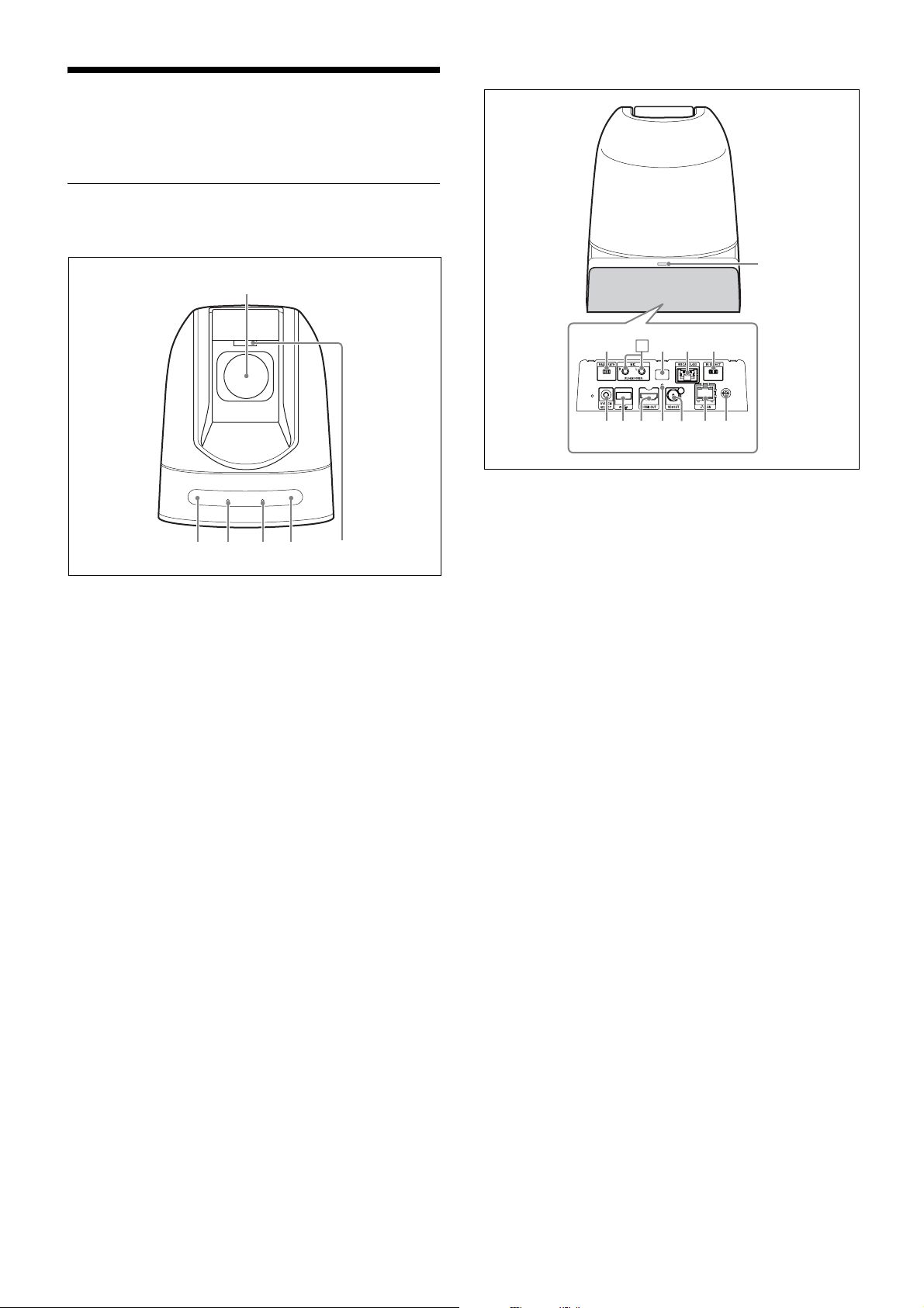
Camera
Front
1
Rear
67889q;
qaqsqd qf qg qh qj
f BAUD RATE switch
Used to switch between 9,600bps and 38,400bps for
the RS-422 baud rate.
a Lens
This is a 30-magnification optical zoom lens.
b Infrared remote commander sensors
These are sensors for the supplied infrared remote
commander.
c POWER lamp
The green light turns on when the camera is connected
to an AC outlet using the supplied AC power adaptor
and AC power cable, or when power is supplied via
the LAN connector with PoE+.
d NETWORK lamp
The green light will turn on when the preparation for
network connection is done and all movements are
available.
e TALLY lamp
The status of video shooting can be indicated by the
lamp.
g MIC input
Input for commercially-available MIC or LINE to
connect an Audio device.
* Switch between MIC and LINE input, as indicated
on page 22.
h Infrared remote commander sensors
These are sensors for the supplied infrared remote
commander.
i VISCA RS-422 connector (RJ-45 8-pin)
To communicate via RS-422, use this connector.
For the connecting cables, see “RS-422 connection
with IP remote controller RM-IP10” (page 20).
j IR SELECT switch
Select the camera number when you operate multiple
cameras with the same infrared remote commander.
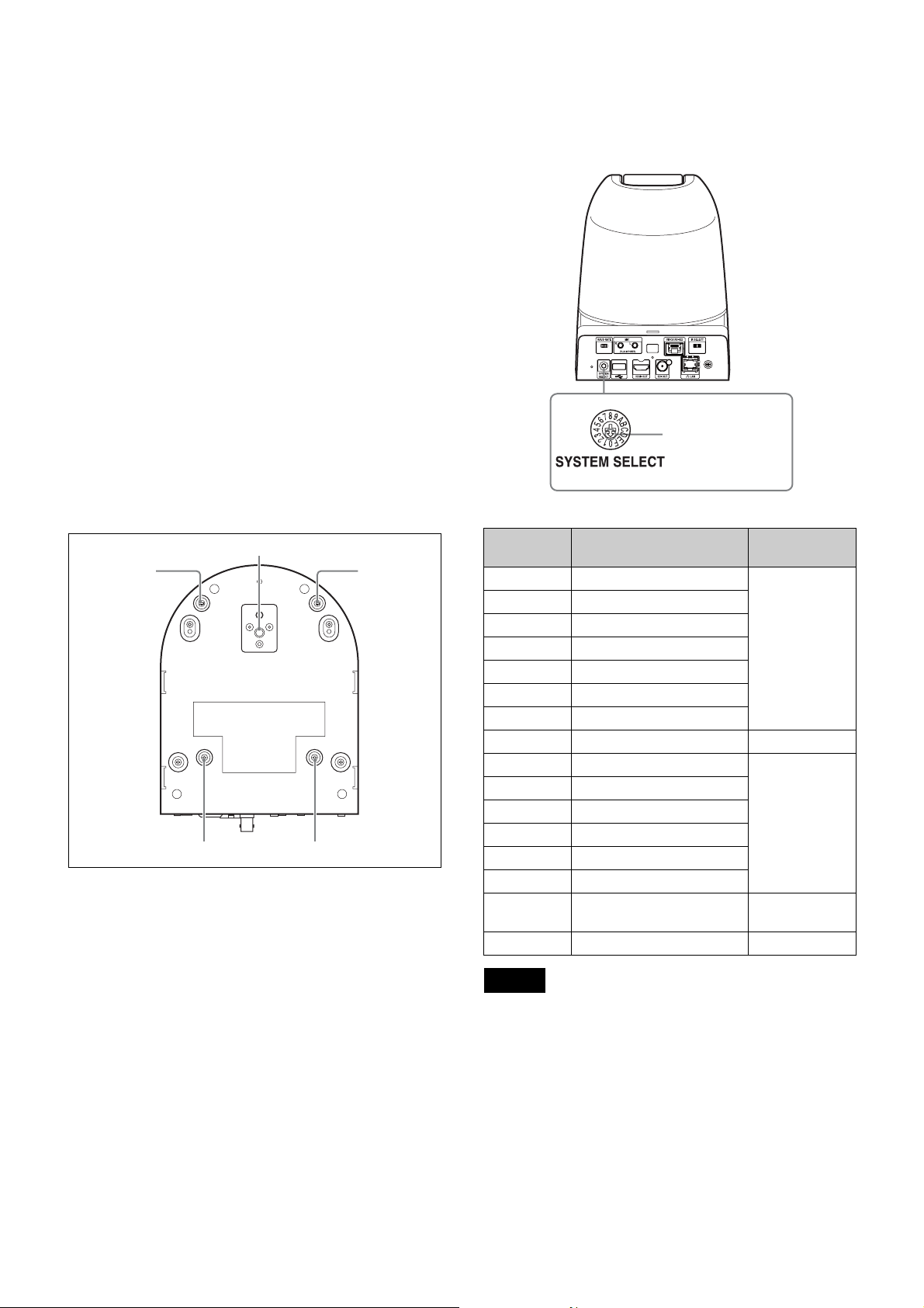
k SYSTEM SELECT switch
Used to set method to output image signal, which is
output via HDMI and SDI OUT video connector.
For details, see “Setting of the SYSTEM SELECT
switch” (page 9).
l USB connector
This is not available to use. It is for maintenance
purposes.
m HDMI OUT video connector
Outputs the image from the camera as an HDMI video
signal.
8
Page 9
n Screw hole for HDMI cable fixing plate
q
q
Mount the supplied “HDMI cable fixing plate”.
o SDI OUT connector
Outputs video from this product as an HD SDI (3GHD SDI compatible) video signal.
p LAN connector (RJ-45 8-pin)
Network communication and PoE+* power supply are
performed by using the network cable (category 5e or
higher, shielded twist pair).
For more information on the connection, refer to the
Operating Instructions included with power supply
system.
(*PoE+: an abbreviation of Power over Ethernet Plus,
which complies with IEEE802.3at)
The green indicator lights when the link is established.
The orange indicator will blink during
communication.
q DC 12 V connector
Connect the supplied AC power adaptor.
Bottom
qk
ql
l
ql
l
r Tripod screw hole
Screw hole to mount tripod.
For details, refer to “Attaching the Camera to a
Tripod” (page 16).
Setting of the SYSTEM SELECT switch
This switch allows you to select the video format of the
signal to be output from the HDMI OUT/SDI OUT
connectors.
This camera
Set this arrow to the
desired video format.
Switch
position
0 1920×1080p/59.94 (A)
1 1920×1080p/59.94 (B)
2 1920×1080p/29.97
3 1920×1080i/59.94
4 1280×720p/59.94
5 1280×720p/29.97
6 1920×1080p/59.94 (A)
7 WEB UI –
8 1920×1080p/50 (A)
9 1920×1080p/50 (B)
A 1920×1080p/25
B 1920×1080i/50
C 1280×720p/50
D 1280×720p/25
E 1920×1080p/59.94 (A) 59.94 Hz
F No output –
Video format
59.94 Hz
system
50 Hz system
system
s Ceiling bracket mounting screw holes
Screw hole to mount the supplied ceiling bracket (A)
when you mount the camera on the ceiling.
For details, refer to “Installing the Camera” (page 16).
Notes
• Configure the setting of the switch before turning the
camera on.
Turn on the power supply after setting the switch.
• Always use a cross slot screwdriver to toggle the
switch. Otherwise, the cross chase might be stripped.
• When the switch is positioned as 7 (WEB UI), the video
format can be set via the external connection.
For details, refer to “Installation Tab” on page 52.
9
Page 10
Infrared Remote Commander
6
1
2
3
4
5
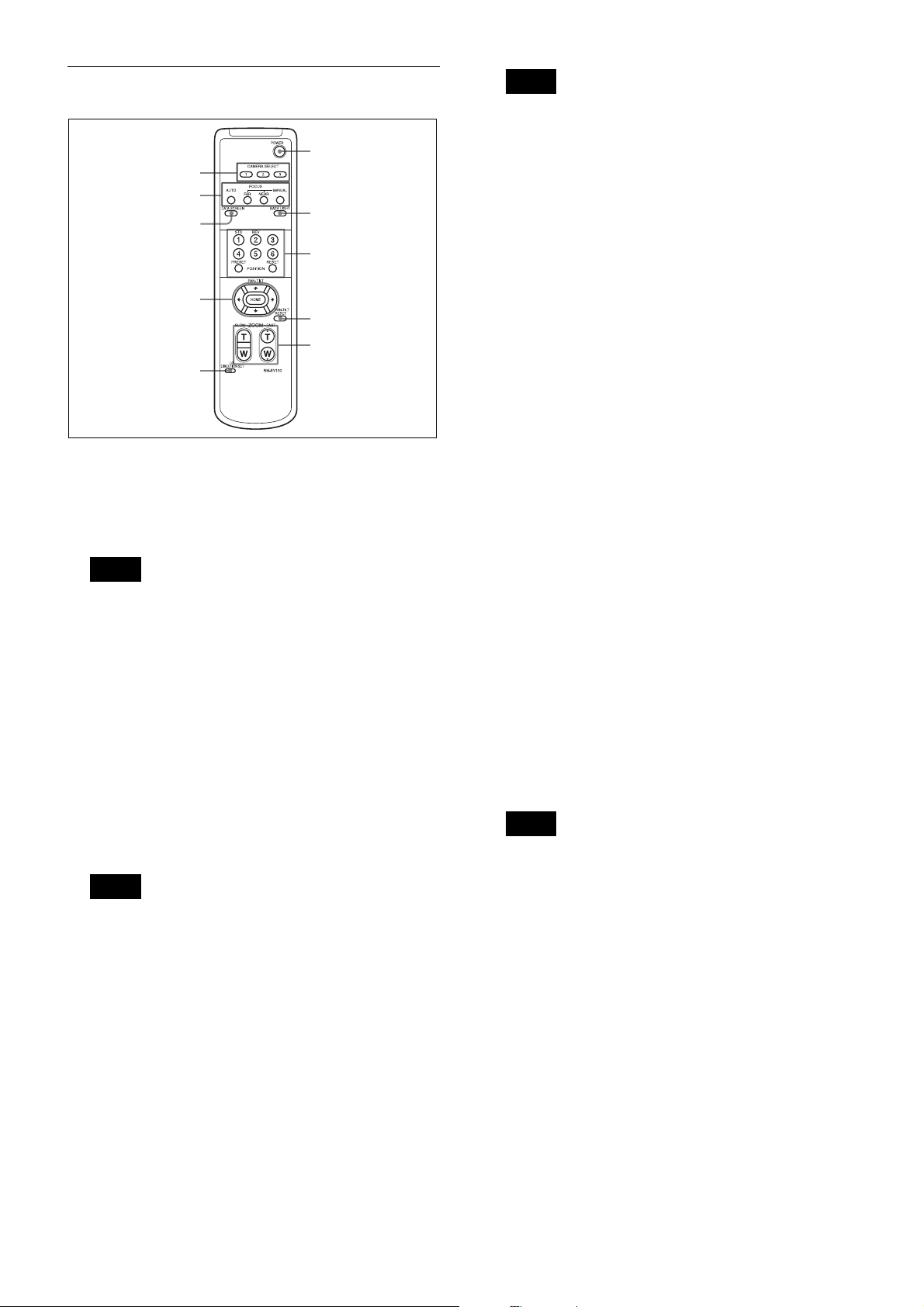
a CAMERA SELECT buttons
Press the button corresponding to the camera you want
to operate with the infrared remote commander.
The camera number can be set using the IR SELECT
switch on the rear of the camera.
Note
If two or more cameras are adjacent and have the same
camera number, they are operated simultaneously
with the same infrared remote commander. When you
install the cameras close to each other, set different
camera numbers.
For the camera number setting, see “Operating
Multiple Cameras with the Infrared Remote
Commander” (page 31).
b FOCUS buttons
Used for focus adjustment.
Press the AUTO button to adjust the focus
automatically. To adjust the focus manually, press the
MANUAL button, and adjust it with the FAR and
NEAR buttons.
Note
Press the MANUAL button and adjust the focus
manually when shooting the following objects.
• White walls and other objects without contrast
• Objects behind glass
• Objects with horizontal stripes
• Objects on which bright lights are cast or reflected
• Nightscapes and other dark objects with blinking
lights
• Lit objects shot with darkened exposure adjustment
or exposure compensation settings
7
8
9
q;
Note
The pan/tilt operation will be disabled when MENU is
displayed (except: PAN/TILT LIMIT or PTZ TRACE
settings).
d PAN-TILT buttons
Press the arrow buttons to adjust the direction of the
camera. Press the HOME button to face the camera
back to the front.
When the menu is displayed, use V or v to select the
menu items and B or b to change the set values. The
selected setting menu is displayed, by pressing the
HOME button when the main menu is displayed. You
can change the menu position with either the B or b
button.
e L/R DIRECTION SET button
Hold down this button and press the REV button to
change the direction of the camera movement opposite
to that indicated by the arrow of the B/b buttons.
To reset the direction of the camera movement, press
the STD button while holding down this button.
f POWER button
Turns on/off the camera output video.
g BACK LIGHT button
Press this button to enable the backlight
compensation. Press it again to disable the backlight
compensation.
h POSITION buttons
Hold down the PRESET button and press button 1 to
6 to store the current camera direction, zooming, focus
adjustment and backlight compensation in the
memory of the pressed number button.
To erase the memory contents, hold down the RESET
button and press button 1 to 6.
Note
These buttons do not function when the menu is
displayed.
i PAN-TILT RESET button
Press this button to reset the pan/tilt position.
j ZOOM buttons
Use the SLOW button to zoom slowly, and the FAST
button to zoom quickly.
Press the T (telephoto) side of the button to zoom in,
and the W (wide angle) side to zoom out.
c DATA SCREEN button
Press this button to display the main menu. Press it
again to turn off the menu. If you press the button
when a lower-level menu is selected, the display goes
back to a higher-level menu.
10
Page 11
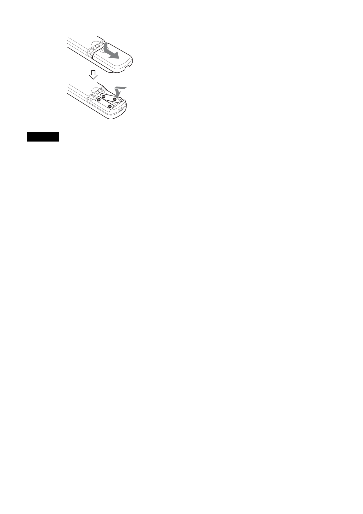
To install batteries
Two R6 (size AA) batteries
(not supplied)
CAUTION
Danger of explosion if battery is incorrectly replaced.
Replace only with the same or equivalent type
recommended by the manufacturer.
When you dispose of the battery, you must obey the law
in the relative area or country.
Installing batteries
Two R6 (size AA) batteries are supplied for Infrared
Remote Commander.
To avoid risk of explosion, use R6 (size AA) manganese
or alkaline batteries.
11
Page 12
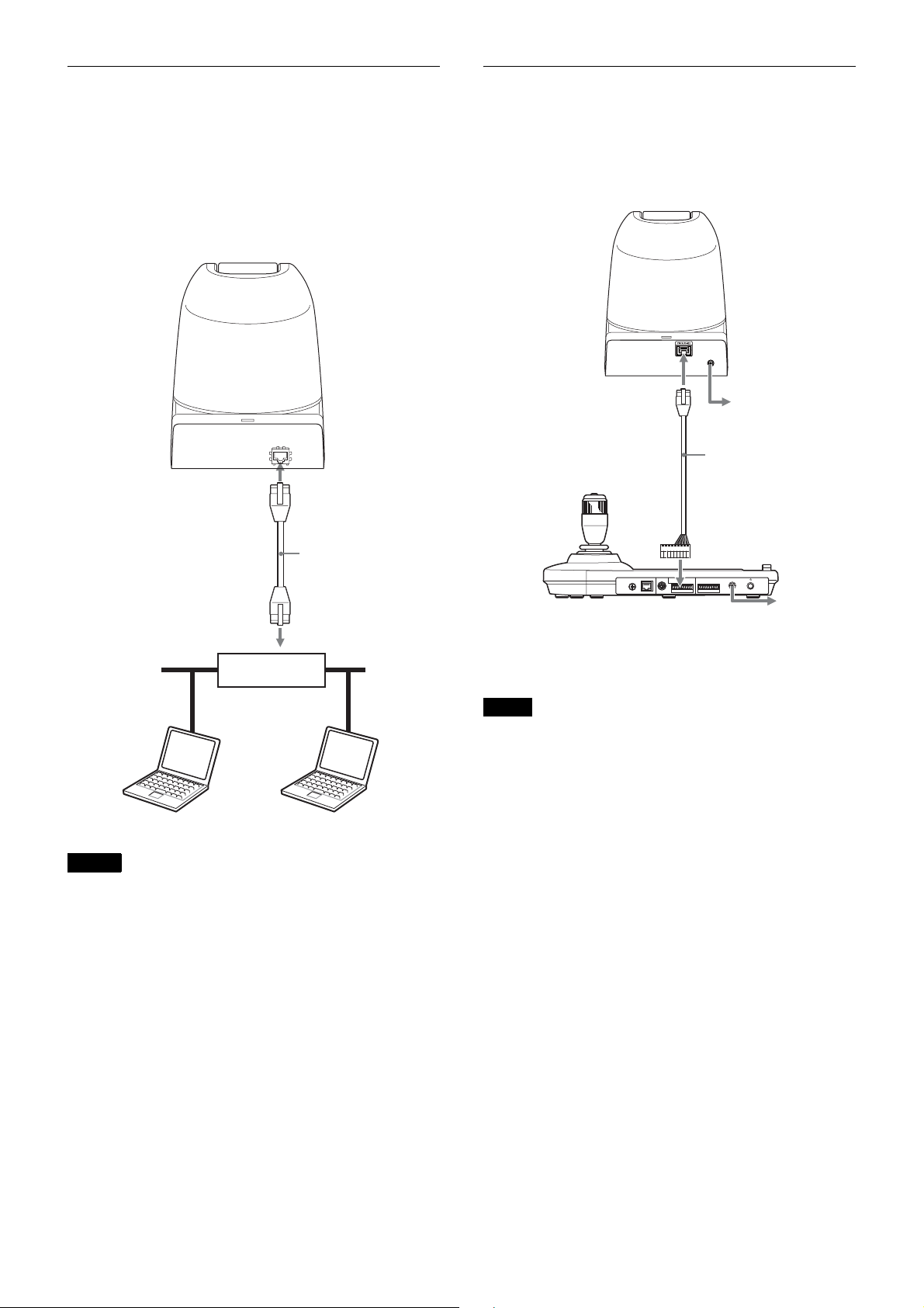
System Configuration
This camera has various system configuration capabilities using optional products. This section describes typical system
examples with the required components and the main usage of each system.
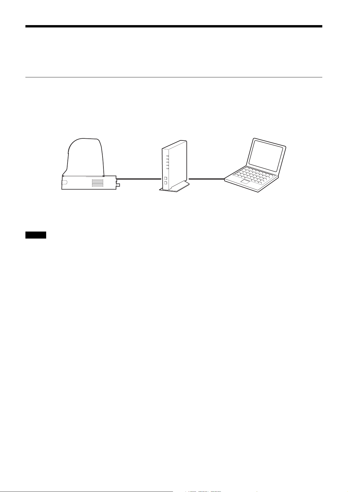
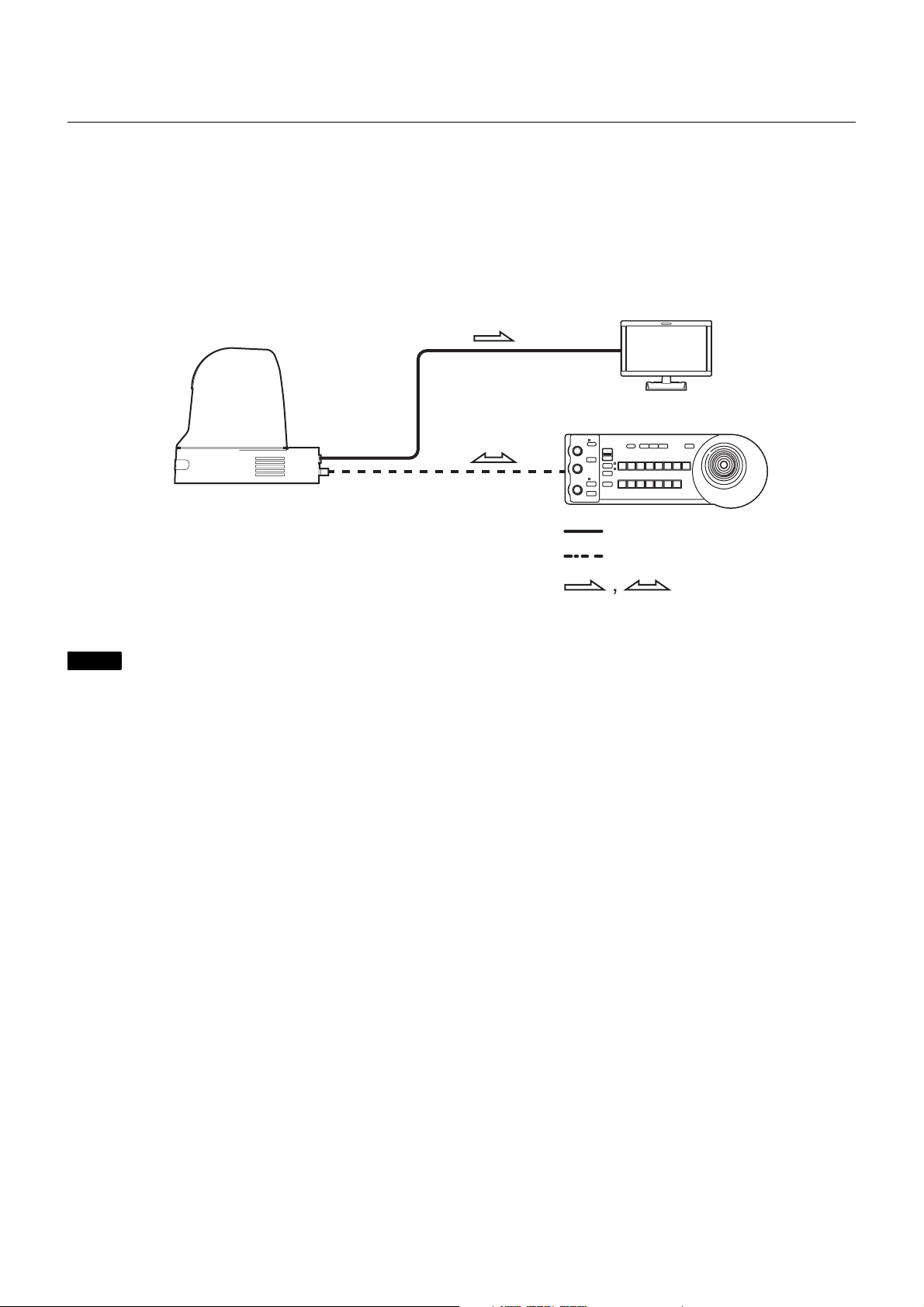
Operating the Camera Via a Network
What you can do with this system
Multiple users can view video and audio from one camera via a network at the same time.
System Configuration
Camera Router or Hub Computer
For details concerning operation and the setting of the camera via a network, see “Operating the Camera Via a Network”
on page 46 or “Setting the Camera Via a Network” on page 51.
Notes
• Factory settings for IP
IP address: 192.168.0.100
Subnet mask: 255.255.255.0
• The maximum number of users that can view changes depending on the video and audio settings.
• If the simultaneous connections via a network increase, the frame rate may decrease.
Operating Environment Requirements
The following operating environment is necessary for the computer to display images and the controls of the camera.
(July 2016)
OS
Windows 7 (32bit version, 64-bit version), Windows 8.1 Pro (32bit version, 64-bit version)*
version, 64-bit version) *
Authorized editions:
Windows 7: Ultimate, Professional
Windows 8.1: Pro
Windows 10: Pro
Web Browser
Windows Internet Explorer Ver. 11.0*
Google Chrome Ver.50.0
CPU
Intel Core i7, 2.8 GHz or higher
Or Intel Core i3 / Intel Core i5 / Intel Core i7 (with built-in Intel HD Graphics)
2
1
1
, Windows 10 Pro (32bit
Memory
2 GB or more
Display
1600 × 1200 pixels or higher
12
Page 13
*1 If you use Windows 8.1, use the Internet Explorer for the desktop user interface (desktop UI).
*2 If you use Windows 10, turn off the tablet mode.
Operating a Camera Using the Remote Controller
What you can do with this system
To perform pan/tilt and zoom operations using the joystick of the remote controller, and to perform the Preset operation
using the button.
System Configuration
HD video monitor
Camera
Remote Controller
(not supplied)
HDMI/HD SDI
VISCA RS-422
Video signal
Remote Control (VISCA) signal
Signal flow
Notes
• Only RS-422 connection is available for VISCA CONTROL.
• The communication speed should be adjusted with the BAUD RATE switch on the back of the unit and the remote
controller.
• To change the video format, you should choose the one you want using the SYSTEM SELECT switch or on the browser
window via a network.
* Settings cannot be changed via the menu displayed on HDMI OUT/SDI OUT.
For details concerning operation and the setting of the camera using the remote controller, see “Operation Using the
Remote Controller” on page 34 or “Setting with the Remote Controller” on page 40.
13
Page 14
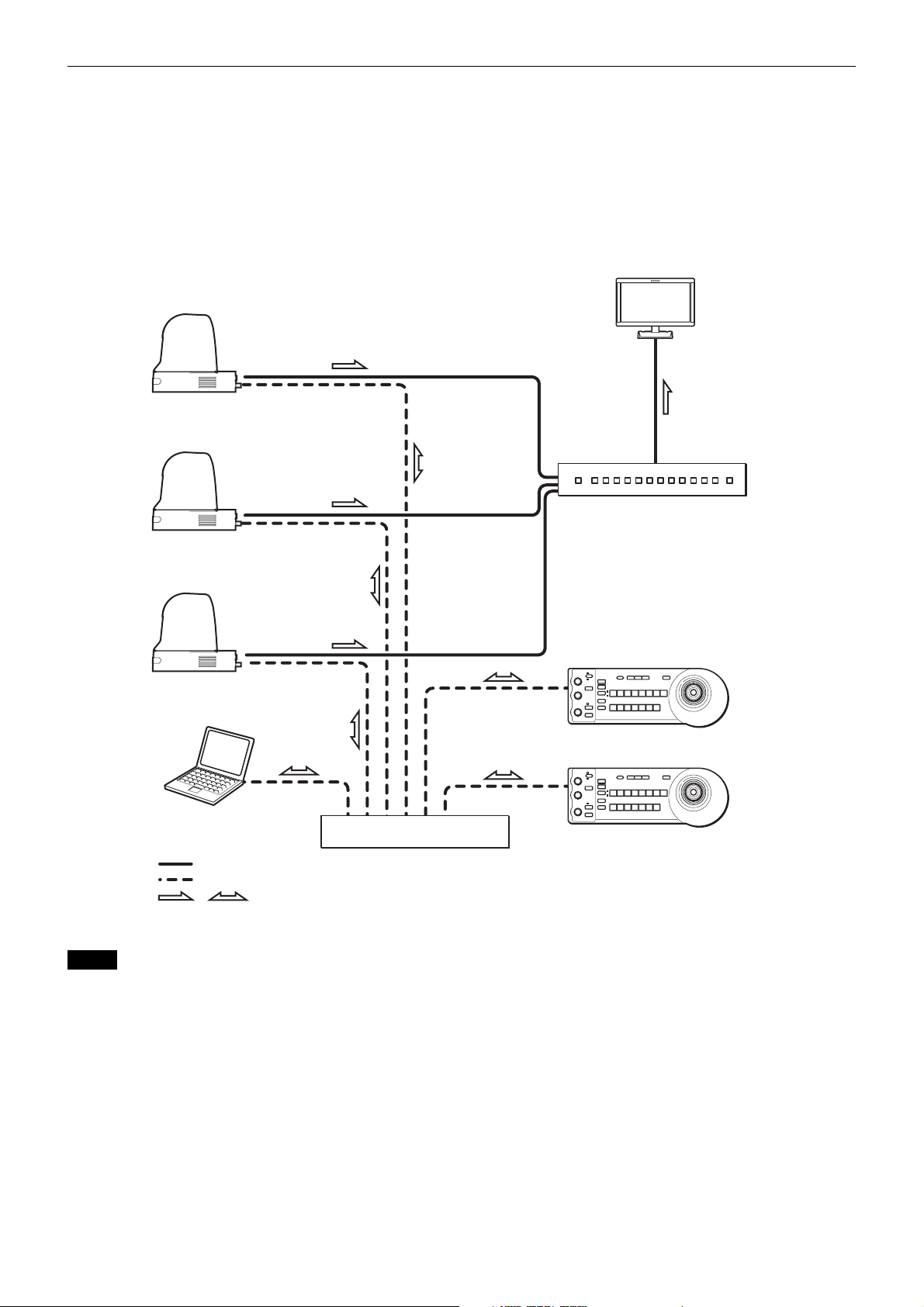
Operating Multiple Cameras Using Multiple Remote Controllers
What you can do with this system
• You can connect up to 112 cameras and five remote controllers.
• The joystick of the remote controller allows comfortable pan/tilt and zoom operations.
System Configuration
HD video monitor
Camera
Camera
Video switcher
Camera
Remote Controller (not supplied)
Note
PC for the setting
Video signal
Remote Control (LAN) signal
Signal flow
,
Switching hub
Remote Controller (not supplied)
When you control the camera by using the LAN connection, use a shielded twisted pair network cable that is category 5e
or higher.
14
Page 15

Precautions for Preventing Access to the Camera by an Unintended Third Party
The camera may be accessed by an unintended third party
on the network, depending on the usage environment.
Changing the user name and password of the camera
administrator from the default settings is highly
recommended for security reasons. If the camera is
accessed by an unintended third party, there may be
undesired effects such as operations or settings that may
interfere with viewing.
Also, this camera’s RTSP stream is not encrypted. Use
the camera in a safe network.
The camera can be fraudulently accessed in a network
environment where a device is connected or connectable
to the network without the administrator’s permission, or
a PC or other network device connected to the network
can be used without any permission. Connect to these
environments at your own risk.
Do not use the browser you use to set the camera to access
other websites while you set or after setting the camera.
You will remain logged in to the camera as long as the
browser is open, so to prevent an unintended third party’s
use or execution of malicious programs, close the browser
after you finish setting the camera.
15
Page 16
Installation and Connection
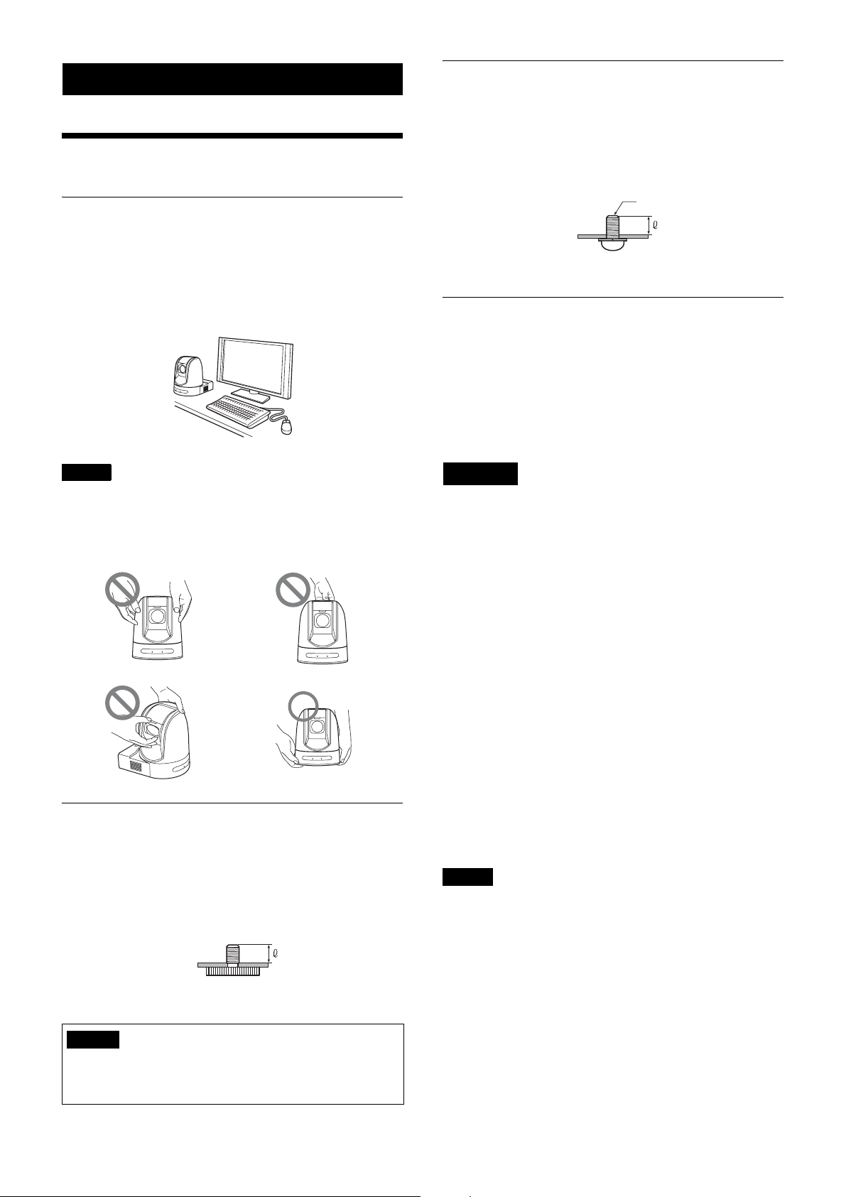
Installing the Camera
Installing the Camera on a Desk
Installing the Camera Using the M3 Fixing Screw Holes
Attach the camera using 4 M3 fixing screw holes located
on the bottom of the camera.
Attach the camera to a fitting with a flat surface using M3 screws
with the following specifications.
M3 screw
Place the camera on a flat surface.
If you have to place the camera on an inclined surface,
make sure that the inclination is less than ±15 degrees to
guarantee pan/tilt performance, and take measures to
prevent it from falling.
Notes
• Do not grasp the camera head when carrying the
camera.
• Do not turn the camera head by hand. Doing so may
result in a camera malfunction.
4 = 3 – 8 mm
1
4 =
/8 – 11/32 inches
Installing the unit on the ceiling
Using the ceiling bracket, wire rope, and screws supplied,
you can attach the camera to the ceiling.
When you install the unit, always install it on a level
ceiling. If you have to install it on a sloping or uneven
ceiling, make sure that the place where you install it is
within ±15 degrees of the horizontal.
CAUTION
• Entrust installation to an experienced contractor or
installer when installing the unit on ceilings or other
high locations.
• When installing the unit in a high location, be sure that
the location and installation components (excluding the
supplied accessories) are strong enough to support the
unit and the mounting bracket, and install the unit
securely. If the components are not strong enough, the
unit may fall and cause serious injury.
• Always install the supplied wire rope to prevent the unit
from falling.
• If you install the unit in a high location, check
periodically, at least once a year, to ensure that the
connection has not loosened. If conditions warrant,
make this periodic check more frequently.
Attaching the Camera to a Tripod
Attach a tripod to the screw hole used for attaching a
tripod on the bottom of the camera.
The tripod must be set up on a flat surface and its screws
tightened firmly by hand.
Use a tripod with screws of the following specifications.
4 = 4.5 - 7 mm
3
4 =
/16 - 9/32 inches
Caution
Installation of the camera using the tripod screws and
screw holes should not be done for installation on a
ceiling or a shelf, etc., in a high position.
Before installation
Determine the shooting direction of the camera, and then
make the holes for the ceiling bracket (B) and the
connecting cables on the ceiling.
Notes
• The connecting cables cannot be passed through ceiling
bracket (B). A hole for the wiring is required in the
ceiling at the back of the unit where it is attached to the
ceiling.
• The recommended tightening torque for each screw are
described in below.
M3: 0.6 N·m (6.1 kgf·cm)
M2.6: 0.4 N·m (4.1 kgf·cm)
16
Page 17
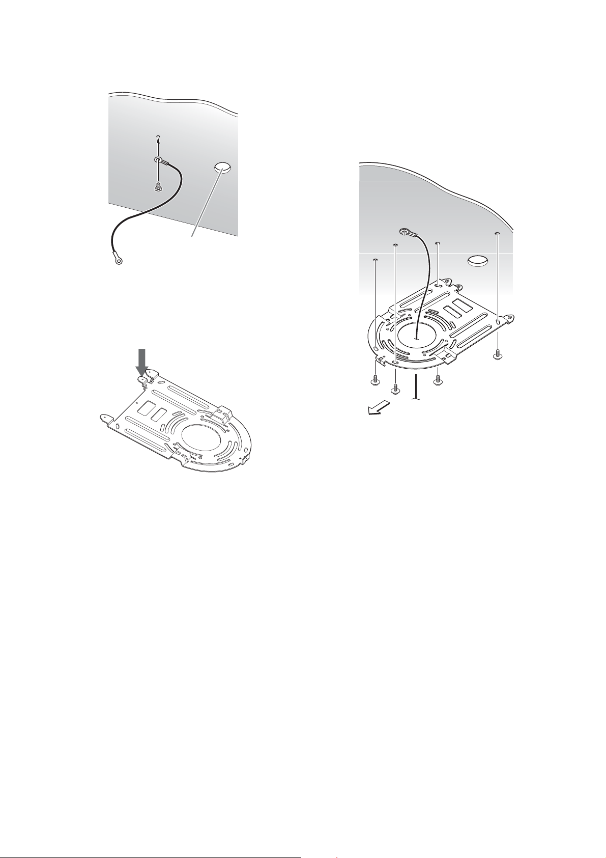
Installation
1
Attach the wire rope to the ceiling.
Ceiling
Hole for connecting cable
1-2
In the case that a wire cannot be attached on the
ceiling, attach the wire on the ceiling bracket (B) as
illustrated below with the supplied screws
(M 3 × 8).
2
Attach the ceiling bracket (B) to the ceiling.
When attaching the ceiling bracket (B) to the ceiling,
it is recommended to fix at the 4 positions illustrated
below.
There are elongated holes for the screws along the
rounded edges of the ceiling bracket (B). Later, the
front of the camera will be positioned along this edge.
Face the camera to the front, adjust the aim, and
attach it securely.
Ceiling
Front of the camera
Ceiling
bracket (B)
17
Page 18
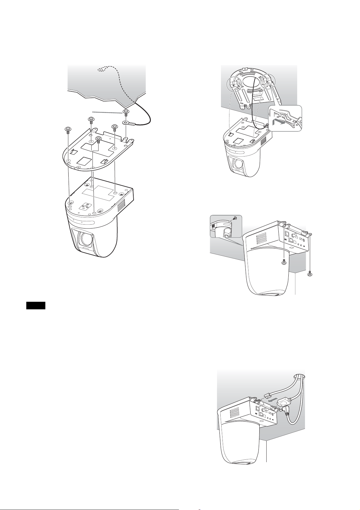
3
Attach the ceiling bracket (A) to the bottom of the
camera using the 4 screws (M 3
× 8) supplied.
Align the bracket holes with the screw holes on the
camera, and attach the bracket to the camera.
Ceiling
Attach
the wire rope.
4
Insert the protrusions raised on the ceiling bracket (A)
into the spaces prepared in the ceiling bracket (B),
and temporarily attach them by pushing the ceiling
bracket (A) to the rear.
Ceiling
bracket
(B)
Ceiling
M 3
× 8
(supplied)
1
4
2
3
Ceiling
bracket (A)
Tighten the screws a bit at a time in the numbered order
shown in the illustration. After all of the screws are
inserted and temporarily tightened properly, securely
tighten each one in turn.
Note
For assembly, use only the screws supplied with the unit.
Using other screws may damage the unit.
Ceiling
bracket (A)
5
While pushing up on the front part of the camera,
attach it using the 3 screws (M 3
× 8) supplied,
starting with the screw at position 1.
Ceiling
1
2
M 3 × 8
(supplied)
Lightly tighten screws temporarily in the order
indicated in the figure. Afterwards, screw each of
them firmly.
3
18
6-1
Connect the cables to the connectors on the rear of
the camera.
Ceiling
Page 19
Notes
• Take the proper steps to ensure that the load of the
cables connected does not cause problems.
• To prevent cables from coming off, it is
recommended to proceed to 6-2 after connecting
the HDMI cable, and then connect other cables.
6-2
To prevent the HDMI cable from coming off, mount
the HDMI cable fixing plate with the supplied screw
(single, M2.6 × 6, black) on the rear side of the
camera, then fix the HDMI cable with a banding
band etc.
Connections
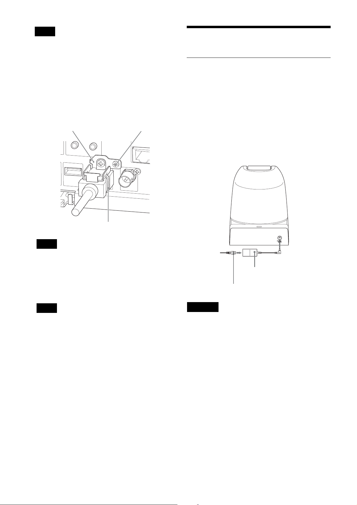
Connecting the power supply
Power is supplied to the unit using the following methods.
• Supplied AC power adapter
• PoE+* (power supply system, which complies with
IEEE802.3at)
* PoE+: an abbreviation of Power over Ethernet plus.
HDMI cable fixing plate
Banding band
Note
Do not attach the HDMI cable on the camera unit, if
you do not use them.
7
Adjust the Eflip function to optimize the ceiling
mounting status via the Web browser or menu
display.
M2.6 × 6 (Supplied)
Power supply with the supplied AC power
adapter
Use the supplied AC power adaptor and AC power cord
to connect the camera to an AC outlet.
This camera
to AC
outlet
AC power adaptor
(supplied)
AC power cord (supplied)
DC 12 V
Note
All preset settings will return to their default when
adjusting the setting of the Eflip function. When
setting, make sure to set the Eflip function before the
preset settings.
Removing the camera
1
Remove the 3 screws used to attach the camera in step
5 of “Installation.”
2
While pushing the entire camera up towards the
ceiling, move the camera to the front.
The hooks will disengage, and you can remove the
camera.
CAUTION
• This product is not equipped with a power switch.
When installing this product, install dedicated cutoff
equipment within the fixed wiring that can be easily
accessed or connect the power plug to an outlet near the
camera where it can be easily inserted/removed. If an
abnormality occurs, apply the cutoff equipment or
remove the power plug.
• When supplying power using the AC power adapter, do
not connect the PoE+ power supply system.
• Wait approximately 10 seconds before turning the
power on again.
19
Page 20
Connecting to the PoE+ (Power over
RS-422 connection with IP remote
Ethernet plus) power supply system
PoE+ (complied with IEEE802.3at) power supply
equipment supplies power via a commercially-available
network cable. For details, refer to the instruction manual
of your power supply device.
This camera
Network cable
(not supplied)
controller RM-IP10
Connect to the IP remote controller using the connection
cable.
This camera
To the AC power
adaptor
RS-422 cable
VISCA RS-422
LAN
RM-IP10 IP
Remote Controller
MODE
DC IN 12V
RS-42 2
RS-232C
VISCA
1919
to the AC adaptor
(supplied with the
RM-IP10)
TALLY/ CO NTACT
!
DC 12V
Hub with PoE+ power
supply function
Notes
• To supply power via PoE+, use a shielded twisted pair
network cable of category 5e or higher.
Do not connect the AC power adapter, when supplying
power via PoE+.
• When power is supplied via PoE+, the POWER light
does not turn on until the initial authentication is
completed (the time varies depending on the model; it
is approximately one minute).
• HDMI video output and the video outputs 2 and 3 via a
network become disabled when power is supplied via
PoE+.
• Wait approximately 10 seconds before turning the
power on again.
• The HD Color Video Camera is to be connected only to
PoE+ networks without routing to the outside plant.
Note
To connect using the VISCA RS-422 connector, create
the connection cable using the RS-422 connector block
which is supplied with the camera and IP remote
controller.
For making the cable, refer to “Using the VISCA RS-422
connector pin assignments” on page 74.
20
Page 21
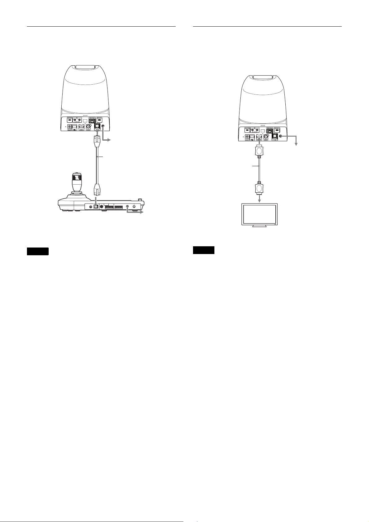
LAN connection with IP remote
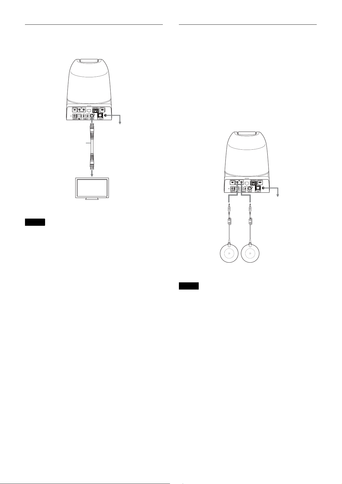
Connecting a Video Monitor, etc.,
controller RM-IP10
This camera
LAN
MODE
RM-IP10 IP Remote
Controller
To the AC power adaptor
Network cable
(not supplied)
RS-42 2
TALLY/CONTACT
RS-232C
VISCA
1919
!
DC 12V
to the AC
adaptor
(supplied with
the RM-IP10)
Equipped with HDMI Input
Connector
This camera
VIDEO OUT
HDMI cable
(not supplied)
to HDMI input
connector
HD video monitor, etc.
To the AC power adaptor
Notes
• Use the network cable of category 5e or higher, shield
twist pair.
• Use the crossover cable if you want to connect directly
to the LAN connector of one camera and one IP remote
controller without using a switching hub.
Notes
• Configure the, VIDEO FORMAT, based on the
specifications of the HD monitor.
• Depending on the performance capabilities of the
HDMI cable, some picture noise may occur. It is
recommended to use a Sony high-speed HDMI cable.
• If the volume of the monitor is set to maximum, a sound
may emit for a moment when activated, depending on
the product. This is not a malfunction.
• It takes approximately 40 seconds for the video to come
out.
• When installing, use attached fixing parts in order to
prevent HDMI cables from removing due to the cable’s
weight or external force.
• This becomes disabled when power is supplied via
PoE+.
21
Page 22
Connecting with monitors with SDI
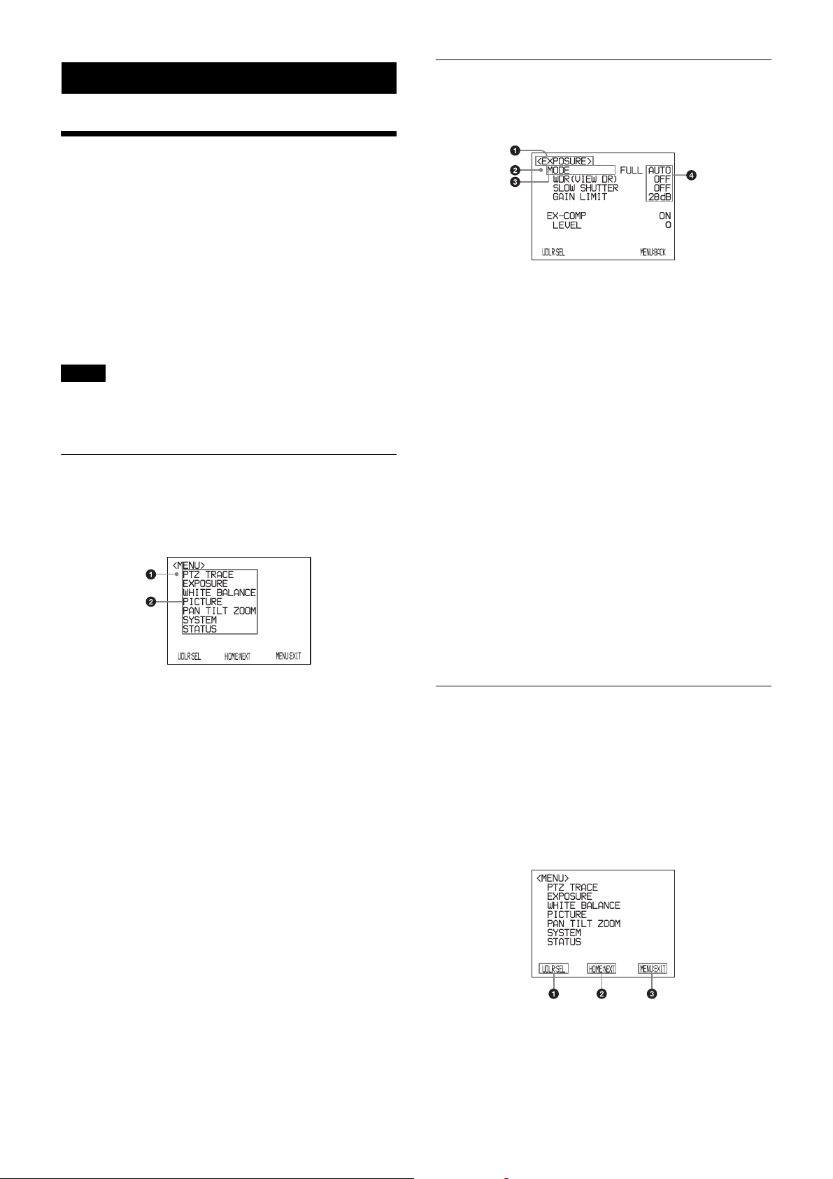
Connection with commercially-
input connectors
This camera
SDI OUT
SDI cable (not
supplied)
HD video monitor, etc.
To the AC power adaptor
To the SDI
input terminal
available microphones etc.
Connect a commercially-available microphone, mixer,
etc.
Input audio will be superimposed to the HDMI OUT/SDI
OUT/IP video output via stereo.
Switch between the microphone input and line input by
selecting either input on the web browser.
Connect a commercially-available microphone when
using the microphone input.
Connect a commercially-available mixer when using the
line input.
This camera
Microphones OUT
To the AC power adaptor
Notes
• Set VIDEO FORMAT based on the specifications of
the HD monitor.
• Depending on the performance of the HD SDI cable,
some noise can be occur on the image. We recommend
to use a 5C-FB cable that meets the HD SDI rating.
• When the volume of the monitor is set to the maximum,
a sound can be heard for a moment on launching on
some devices. This is not a malfunction.
• It takes approximately 40 seconds for the video to come
out.
• When power is supplied via PoE+, it takes
approximately 90 seconds depending on the PoE+
device.
PCS-A1 (not supplied) etc.
Notes
• Do not place the camera near devices that may generate
noise.
• If you place a microphone near this camera, it may pick
up the sound from the camera.
Check the audio of the microphone input in advance
when installing.
• When microphone input is selected, the unit supplies
2.5 VDC Plug-in-power. Do not connect a nonsupported microphone when the microphone input is
selected.
22
Page 23
Adjusting and Setting with Menus
About On-Screen Menus
You can change various settings, such as shooting
conditions and system setup of the camera, while
observing menus displayed on a connected computer
screen.
This section explains how to read the on-screen menus
before starting menu operations.
Setting Menus
The setting menu selected on the main menu is displayed.
For the overall menu configurations, see “Menu
Configuration” (page 69).
Note
You cannot perform pan/tilt operations while the menu is
displayed.
This menu will be shown only for HDMI OUT/SDI OUT.
Main Menu
To display the main menu, press the DATA SCREEN
button on the supplied infrared remote commander.
a Selected item
Selects a setting menu.
The currently selected item is shown in red.
The selected item shifts up or down when you press the
V or v button on the infrared remote commander.
b Menu items
To display a setting menu, select one using the V or v
button on the infrared remote commander and press
the HOME button on the infrared remote commander.
The menu display position changes when you press the
b or B button in the main menu.
a Setting menu
The name of the setting menu currently selected is
displayed here.
b Selected item
Selects a setting item.
The currently selected item is shown in red.
The selected item shifts up or down when you press the
V or v button on the infrared remote commander.
c Setting items
The setting items for this setting menu are displayed.
Select the setting item using the V or v button on the
infrared remote commander.
d Set value
The currently set values are displayed.
To change a set value, use the B or b button on the
infrared remote commander.
For the default value of each setting item, see “Menu
Configuration” (page 69).
Control Button Display Section
Names of buttons displayed on the monitor are different
from buttons on the infrared remote commander to be
used.
Use the proper buttons on the infrared remote
commander, referring to the following pictures.
Main menu
23
Page 24

a Indicates that you can select a menu item by V or v
button on the infrared remote commander. The
selected item is shown in red.
EXPOSURE Menu
b Indicates that you can move to the next layer by
pressing the HOME button.
c Indicates that you can return to the normal display by
pressing the DATA SCREEN button.
Setting menu
a Indicates that you can select the setting item by using
the V
or v button and you can change the set value by
using tthe B or b button.
b Indicates that you can return to the main menu by
pressing the DATA SCREEN button.
Note
For detailed information on how to connect and VISCA
command list, refer to the Technical Manual of the
camera. For details on obtaining a Technical Manual,
consult your Sony dealer.
The EXPOSURE menu is used to set the items related to
the exposure.
This can be set via the Web browser.
See “Exposure” (page 54).
MODE (exposure mode)
FULL AUTO: The exposure is adjusted automatically
using the sensitivity, electronic shutter speed, and
iris.
BRIGHT: Adjust the brightness level (LEVEL)
manually.
SHUTTER PRI: Shutter Priority mode. The exposure is
adjusted automatically using the sensitivity and iris.
Adjust the electronic shutter speed (SPEED)
manually.
IRIS PRI: Iris Priority mode. The exposure is adjusted
automatically using the sensitivity and electronic
shutter speed. Adjust the iris (IRIS) manually.
MANUAL: Adjust the sensitivity (GAIN), electronic
shutter speed (SPEED) and iris (IRIS) manually.
When you select one from among the various exposure
modes, some of the following setting items that are
required for the selected mode appear.
GAIN: Select the gain from among the following:
0, 3, 6, 9, 12, 15, 18, 21, 24, 27, 30, 33, 36, 39, 43 dB
SPEED: Select the electronic shutter speed from among
the following:
For the 59.94/29.97 video format:
1/1, 1/2, 1/4, 1/8, 1/15, 1/30,
1/60, 1/90, 1/100, 1/125, 1/180, 1/250,
1/350, 1/500, 1/725, 1/1000, 1/1500,
1/2000, 1/3000, 1/4000, 1/6000,
1/10000 sec.
For the 50/25 video format:
1/1, 1/2, 1/3, 1/6, 1/12, 1/25,
1/50, 1/75, 1/100, 1/120, 1/150, 1/215,
1/300, 1/425, 1/600, 1/1000, 1/1250,
1/1750, 1/2500, 1/3500, 1/6000,
1/10000 sec.
IRIS: Select the iris from among the following:
CLOSE, F14, F11, F9.6, F8.0, F6.8, F5.6, F4.8, F4.0,
F3.4, F2.8, F2.4, F2.0, F1.6
LEVEL: Select the brightness level.
Select the brightness level from among 0, 5 to 31.
24
Page 25

WDR (VIEW-DR): When MODE (exposure mode) is
set to FULL AUTO, the camera distinguishes light
and dark areas in the same scene, adjusts the
brightness for dark areas, and also controls the blown
out highlights.
You can select the wide dynamic range mode from
among OFF, LOW, MID and HIGH.
Notes
• You can set the wide dynamic range mode when WDR
(VIEW-DR) is set to FULL AUTO only.
• When changing WDR (VIEW-DR), a change in screen
luminance occurs for a moment.
• When the change of exposure is big, the screen may
stop for a moment.
• The audio will be muted for approximately 1 second
when WDR (VIEW-DR) switches.
WHITE BALANCE Menu
The WHITE BALANCE menu is used to select the white
balance mode.
This can be set via the Web browser.
See “White balance” (page 55).
GAIN LIMIT: Select the upper limit of the gain rise in
FULL AUTO, SHUTTER PRI and IRIS PRI modes.
Select from among 9, 12, 15, 18, 21, 24, 27, 30, 33,
36, 39, 43 dB.
EX-COMP (exposure compensation)
When MODE is set to one of FULL AUTO, SHUTTER
PRI or IRIS PRI, set this item to ON to enable exposure
compensation. When you set EX-COMP to ON, LEVEL
appears and you can select the exposure compensation
level from among the following:
–7, –6, –5, –4, –3, –2, –1, 0, 1, 2, 3, 4, 5, 6, 7
If you set the level to 0, exposure compensation will be
disabled. Level 7 is the brightest and –7 is the darkest
compensation value.
When EX-COMP is set to OFF, exposure compensation
does not function.
SLOW SHUTTER
When you set the mode to ON, the camera automatically
uses slow shutter speed for exposure as the illumination
of the object to be shot decreases. This mode is only
available when AE mode is set to FULL AUTO.
MODE (white balance mode)
Select the white balance mode from among the following:
AUTO, IN DOOR, OUT DOOR, ONE PUSH, ATW
(Auto Tracing White Balance), MANUAL.
When you select MANUAL, R.GAIN (R gain), B.GAIN
(B gain) will be displayed. These can be adjusted within
the range between 0 and 255.
When you select the ONE PUSH mode
Perform the following while the white balance menu is
displayed.
1
Zoom in on a white subject in the center of the screen.
2
Press the HOME button of the supplied infrared
remote commander.
The one-push white balance adjustment is activated.
25
Page 26

PICTURE Menu
The PICTURE menu is used to set the items related to the
picture.
See “Picture” (page 56) or “Installation Tab” (page 52).
APERTURE (aperture compensation)
Select the aperture compensation level from among MIN,
1 to 14 and MAX.
HIGH RESOLUTION (high resolution mode)
You can set this mode to ON or OFF. When set to ON,
you can enjoy emphasised edge and high-resolution
images.
• The image stabilizer may not be effective in an
installation environment where high frequency
vibration is present. In this case, set the image stabilizer
function to OFF.
Note
When this is turned on, the image will have more noise
than when shooting with it turned off.
NOISE REDUCTION (noise reduction)
You can enjoy clearer images by removing unnecessary
noise (fixed pattern and randomised noise). You can
select 6 levels from OFF (MIN), 1 to 5 (MAX).
IMAGE STABILIZER (image stabilizer)
You can select this function according to the shooting
conditions.
OFF: The image stabilization feature becomes disabled.
ON: The image stabilization feature becomes enabled.
When set to ON, you can obtain steadier images if
vibration is present. This stabilizer is effective for
vibration frequencies around 10 Hz. This function utilizes
digital zoom; therefore, the angle of view and resolution
of images may be affected. However, image sensitivity is
retained.
Notes
• The image stabilizer function is not effective during
pan/tilt operations. It may take some time for the image
to stabilize after performing pan/tilt operations.
• If the image stabilizer function is already enabled, it
may take some time for the image to stabilize after
turning on the power of the camera.
• Depending on the installation conditions, the image
stabilizer may not be effective.
• When the image stabilizer function is enabled, the
subject appears closer.
26
Page 27

Setting the range of LEFT/RIGHT movement
PAN TILT ZOOM Menu
The PAN TILT ZOOM menu is used to select the pan/tilt/
zoom mode.
This can be set via the Web browser.
See “PTZF control Tab” (page 63).
PAN/TILT LIMIT (PAN/TILT LIMIT)
When you set PAN/TILT LIMT to ON, you can limit the
range to pan/tilt.
You can select the following values:
RIGHT: +170° to –169°, selectable in 1° steps.
LEFT: +169° to –170°, selectable in 1° steps.
UP: +90° to –29° (IMAGE FLIP:OFF)
+30° to –89° (IMAGE FLIP:ON)
selectable in 1° steps.
DOWN: +89° to –30° (IMAGE FLIP:OFF)
+29° to –90° (IMAGE FLIP:ON)
selectable in 1° steps.
Notes
• If you turn the PAN/TILT LIMIT from OFF to ON, the
stored positions will be cleared.
Perform PAN/TILT LIMIT first, then preset.
• If you change the PAN/TILT LIMIT settings to OFF,
all set values will return to the factory settings.
• The set value displayed will be updated, when you
release the joystick right/left operation. The display
remains during the pan/tilt operation.
• PAN/TILT LIMIT will be applied immediately after it
is set. If you want to reflect the status just before the
power is turned off when turning the camera on again,
set POSITION 1 to remember the setting.
(IMAGE FLIP : OFF)
CENTER (0°)
–170° +170°
Setting the range of UP/DOWN movement
(IMAGE FLIP : OFF)
+90°
0°
–30°
Note
When you turn the camera to the right or left beyond the
90° with the camera pointed downward by 30°, the
camera may be caught on the lens, depending on the zoom
position of the lens.
PAN/TILT SLOW (Slow Pan Tilt mode)
If you turn the function ON, the pan/tilt movement will
slow, making it easier to shoot slow moving targets.
D-ZOOM (digital zoom)
You can set digital zoom to ON or OFF. When set to OFF,
digital zoom does not operate, and only optical zoom is
available. When set to ON, digital zoom takes over after
optical zoom reaches MAX (×30). Up to ×360 can be
zoomed digitally.
27
Page 28

SYSTEM Menu
STATUS Menu
As this menu is for maintenance purpose, users cannot
operate it.
The STATUS menu is used to display the settings
selected with the menus.
The STATUS menu consists of PAGE1 to PAGE4.
This menu only displays the current menu settings, and
you cannot change them with this menu.
PAGE1: Shows the settings selected with the
EXPOSURE menu.
PAGE2: Items in the WHITE BALANCE menu and the
PICTURE menu
PAGE3: Shows the settings selected with the PAN TILT
ZOOM menu.
PAGE4: Settings of AUDIO mode, VIDEO mode, and
VISCA transmission baud rate
Note
The current video format and the VISCA baud rate
communication for the camera are displayed. If you
adjust BAUD RATE and SYSTEM SELECT switches on
the back after you turn on the power, these new settings
are ignored and not changed on the display.
28
Page 29

Operation Using the Supplied Infrared Remote Commander
Before Operating
Before operating the camera, check that the camera and
peripheral devices are properly installed and connected.
For details, see “Setting of the SYSTEM SELECT switch”
(page 9), “Installing the Camera” (page 16) and
“Connections” (page 19).
Turning on the Power
This camera
DC 12 V
Note
The supplied infrared remote commander may not work
correctly near the inverter lighting fixtures. In such a case,
try to install the camera far from the inverted luminaire.
You can check whether or not the installed location is
good for the usage of the infrared remote commander.
to AC outlet
POWER lights.
1
Connect the camera to an AC outlet using the
supplied AC power adaptor and AC power cable or to
a LAN connector for PoE+.
The power is turned on and the POWER light turns
on.
The camera automatically pans and tilts to come to
the position stored in POSITION 1 when the power is
turned on. (Pan/Tilt reset)
After this, SDI OUT and HDMI OUT images are
output and the NETWORK light comes on. Then, all
operations become available (up to two minutes).
Note
When power is supplied via PoE+, the POWER light does
not come on until the initial authentication is completed
(the time varies depending on the model; it is
approximately one minute).
29
Page 30

2
Turn on the peripheral devices.
To switch ON/OFF the video output using the
infrared remote commander
You can switch ON/OFF the video output using the
POWER switch on the infrared remote commander when
supplying power to the camera.
When the POWER is off, the POWER/NETWORK lamp
will go out.
POWER
POWER/NETWORK
lights
Pan/Tilt and Zoom Operation
If the camera moves in a different direction from
the one you intended
The camera is preset so that the image output from the
camera is rotated toward the right whenever you press the
b button.
To face the camera toward the opposite
direction
You might wish to face the camera toward the opposite
direction from that of the button you pressed, for
example, when you change the direction of the camera
while checking the picture on the screen. In such a case,
press the 2 (REV) button while holding down the L/R
DIRECTION SET button.
Arrow button Movement of the
camera
To reset the setting
To reset the setting, press the 1 (STD) button while holding down
the L/R DIRECTION SET button.
Arrow button Movement of the
camera
Setting
While holding
down
Press
Setting
Panning and Tilting
2
1
Press the POWER switch.
You can turn on and off the video output of the unit.
When it is ON, the camera automatically resets pan/
tilt and moves the Preset1 position.
2
Press the arrow button to pan or tilt the camera.
While checking the picture on the screen, press the
desired arrow button.
To move the camera little by little, press the button
just for a moment.
To move the camera in a wide range, press and hold
the button.
To move the camera diagonally, press the B or b
button while holding down the V or v button.
While holding
down
Press
Note
The setting above only changes the signal emitted from
the infrared remote commander, and does not change the
setting of the camera itself. Therefore, repeat the setting
for each infrared remote commander if you are using
more than one infrared remote commander.
To face the camera back to the front
Press the HOME button.
30
Page 31

Zooming
Press either of the ZOOM buttons.
Subject appears
closer. (Telephoto)
Subject appears
farther away.
(Wide angle)
Zooms in or out
fast (FAST side)
Zooms in or out
slowly (SLOW side)
Note
When you perform pan/tilt operation while the camera is
in the telephoto mode, the moving speed of the image on
the screen may be a little jerky.
Operating Multiple Cameras with the Infrared Remote Commander
Adjusting the Camera
Focusing on a Subject
Focusing the camera on a subject
automatically
Press the AUTO button.
The camera focuses on the subject at the center of the
screen automatically.
1
Set the IR SELECT switch on the rear of the camera
you want to operate to 1, 2 or 3.
2
Press the CAMERA SELECT button on the infrared
remote commander that corresponds to the number
set in step 1.
CAMERA
SELECT
Then, you can operate the camera(s) specified by number.
Every time you operate the camera(s) using the infrared
remote commander, the CAMERA SELECT button
pressed in step 2 lights.
Focusing the camera on a subject
manually
After pressing the MANUAL button, press either the
FAR or the NEAR button to have the camera focus on the
subject.
Focusing on a
far subject
Focusing on a
near subject
Shooting with Back Lighting
When you shoot a subject with a light source behind it, the
subject becomes dark. In such a case, press the BACK
LIGHT button.
To cancel the function, press the BACK LIGHT button
again.
Subject
appears
brighter.
Note
The BACK LIGHT function is effective if MODE is set
to FULL AUTO in the EXPOSURE menu of the camera.
31
Page 32

Presetting Feature
Up to 6 combinations of settings (6 positions) including
camera position, zooming, focusing, and backlighting,
can be preset.
For details of the camera settings to be preset, see “Initial
value and preset” (page 71).
1
Press the PAN-TILT RESET button to reset the pan/
tilt position.
Notes
• When the power is turned on, the camera starts with the
settings stored in POSITION 1.
• If you want to retain the previous pan and tilt positions,
etc. before the power is turned off and turned on again,
store those positions in POSITION 1.
• When you are storing or cancelling the settings in one
POSITION, you cannot call up, store or cancel the
settings in another POSITION.
• You can register, call, or delete the preset even while
the menu is being displayed. However, you cannot
change the position with the pan/tilt operation.
• If you turn the PAN/TILT LIMIT from OFF to ON, the
stored positions will be cleared.
Perform PAN/TILT LIMIT first, then preset.
• Please note that if you flip the image, the set position
will be cleared.
2
Adjust the position, zooming, focusing and
backlighting of the camera (pages 30 and 31).
3
While holding down the PRESET button, press any of
the POSITION buttons, 1 to 6, in which you want to
store the settings.
Press a POSITION
button.
While holding
down this button
Recalling the stored settings
Press any of the POSITION buttons, 1 to 6, in which you
have stored the settings.
Cancelling the preset memory
While holding down the RESET button, press the
POSITION button from which you want to cancel the
settings.
Press a POSITION
button.
While holding
down this button
32
Page 33

PTZ TRACE Feature
You can record and playback up to eight different
operations of pan, tilt, and zoom to the maximum length
of 180 seconds using the infrared remote control.
Playing back pan/tilt/zoom operations
1
When the menu is not displayed, press the POSITION
NO button of the same number as the TRACE NO
you want to playback once.
Move to the playback start position.
Notes
• Other operations are not available during recording or
playing back.
• Since Positions 1 through 6 of the infrared remote
control are used for playback, be sure that they do not
overlap with preset functions.
• Since the IR remote commander has only POSITION 1
through 6 buttons, 7 and 8 cannot be played back.
• If you turn the PAN/TILT LIMIT from OFF to ON, the
stored operation will be cleared.
Perform PAN/TILT LIMIT first, then preset.
• Please note that if you flip the image, the stored
operation will be cleared.
Recording pan/tilt/zoom operations
1
Press the DATA SCREEN button on the infrared
remote control to display the main menu.
Using the arrow buttons, move the cursor to select
PTZ TRACE. Press the HOME button to open the
PTZ TRACE menu.
2
On the TRACE NO setting items in the PTZ TRACE
menu, use the arrow buttons to select the number you
want to register.
This TRACE NO value will be the POSITION NO of
the infrared remote control during playback.
3
On the ACTION setting items, use the right or left
arrow buttons to select START POSITION SET.
Pressing the HOME button allows you to pan/tilt/
zoom with the arrow and ZOOM buttons. Press the
HOME button again when the camera moves to the
initial position to start recording.
The initial position settings will be completed.
2
When you press the same button again, the stored
playback of pan/tilt/zoom operation starts.
3
Press the HOME button during the recording
playback to end the playback immediately.
4
If you operate pan/tilt/zoom during playback, the
playback ends immediately and then it follows the
pan/tilt/zoom operation via the remote control.
Note
There is no pause feature.
Deleting pan/tilt/zoom operations
1
Press the DATA SCREEN button on the infrared
remote control to display the main menu.
Using the arrow buttons, move the cursor to select
PTZ TRACE.
2
On the TRACE NO menu, use the right and left arrow
buttons to select the number you want to delete.
3
On the ACTION menu, use the right and left arrow
buttons to select DELETE.
The recording is deleted when you press the HOME
button.
4
On the ACTION setting items, use the arrow buttons
to select RECORD/STOP.
The recording starts when you press the HOME
button (the MENU screen does not get turned off).
5
When operation recording starts, the REMAIN (SEC)
countdown will start. The recording will finish when
the count reaches 0 or when the HOME button is
pressed again.
6
You can review your recorded operation when you
press the HOME button after selecting PREVIEW
using the arrow buttons on the ACTION menu.
33
Page 34

Operation Using the Remote Controller
This chapter describes how to operate the camera using
the optional remote controller.
When you make the settings of the camera using the
remote controller, see “Setting with the Remote
Controller” on page 40.
Before operating, check that the camera, the remote
controller, and peripheral devices are properly installed
and connected.
For details, see “System Configuration” on page 12.
Notes
• You can select the IP connection and the serial
connection (RS-422) for the connection between the
camera and the remote controller. Set the
communication speed of the VISCA RS-422 connector
of the connected camera using the serial connection to
be the same speed of the remote controller. For details,
see “Location and Function of Parts and Controls” —
“BAUD RATE switch” (page 8).
• When performing the IP output of video and audio, the
response of the camera to operation from the remote
controller may delay.
• For details of the remote controller settings, see the
Operating Instructions of the remote controller.
Preparation
12
1
Connect the camera to an AC outlet using the
supplied AC power adaptor and AC power cable or to
a LAN connector for PoE+.
The power is turned on and the POWER light turns
on.
The camera automatically pans and tilts to come to
the position stored in POSITION 1 when the power is
turned on. (Pan/Tilt reset)
After this, SDI OUT and HDMI OUT images are
output and the NETWORK light comes on. Then, all
operations become available (up to two minutes).
RESET
JOYSTICK
VALUE
LOCK
POSITION
KNOB
RESET
–+
R
PRESET
BRIGHT
–+
FOCUS
NEAR FAR
MODE
B
AUTO
AUTO
MANUAL
ONE PUSH
AF
GROUP
1 2 3 4 5 6 7 8
SHIFT
910111213141516
GROUP
SELECT
POWER
1
234567
POWER CAMERA
BLACK
PAN-TI LT
ONE PUSH
LIGHT
RESET
POSITION
CAMERA
MENUGROUP
AWB
Note
When power is supplied via PoE+, the POWER light does
not come on until the initial authentication is completed
(the time varies depending on the model; it is
approximately one minute).
2
Press the ON/OFF switch on the remote controller to
turn it on.
The CAMERA button representing the camera whose
power was turned off last lights.
(The CAMERA 1 button lights by default.)
3
Turn on the peripheral devices.
Notes
• Be sure to turn on the power of the camera before the
power of the remote controller. Otherwise, the remote
controller may not recognize the connected camera.
• After turning on the power of the camera, wait more
than two minutes and turn on the power of the remote
controller. Otherwise, the connection may not be
recognized.
34
Page 35

Operating a Camera
Pan/Tilt and Zoom
Using the Remote
Controller
When the camera and the remote controller are connected
with RS-422, only one camera can be connected to one
remote controller.
When this camera is connected with RS-422, Camera
Address 1 is automatically assigned.
Operating Multiple Cameras Using Multiple Remote Controllers
When using the camera and the remote controller with the
IP connection, up to 112 cameras and 5 remote controllers
can be operated.
For details on how to assign camera addresses, refer to the
Operating Instructions supplied with the remote
controller.
Operation
Panning and Tilting
PAN-TILT RESET
JOYSTICK
VALUE
LOCK
POSITION
KNOB
RESET
–+
R
PRESET
MODE
BRIGHT
SHIFT
GROUP
–+
B
SELECT
AUTO
FOCUS
AUTO
POWER
MANUAL
ONE PUSH
AF
NEAR FAR
1
Press the CAMERA button corresponding to the
camera you want to operate.
2
Pan or tilt the camera using the joystick.
While checking the picture on the screen, incline the
joystick in the desired direction.
The panning/tilting speed changes according to the
angle at which you incline the joystick.
Release the joystick to stop panning/tilting.
To face the camera back to the front
Press the upper button on the joystick for 1 or 2 seconds.
BLACK
PAN-TILT
ONE PUSH
LIGHT
RESET
AWB
POSITION
GROUP
1 2 3 4 5 6 7 8
910111213141516
CAMERA
1
234567
12
MENUGROUP
Press for 1 or 2 seconds.
If you accidentally move the camera with
your hand
Press the PAN-TILT RESET button to perform the pan/
tilt reset action.
35
Page 36

If the camera moves in a different
direction from that you intended
The camera is preset to face toward the right whenever the
joystick is inclined to the right. If you wish to face the
camera toward the opposite direction from the direction
in which you inclined the joystick, for example, when you
change the direction of the camera while checking the
picture on the screen. In such a case, you can change the
panning direction to the opposite direction you inclined
the joystick by using the L/R DIRECTION switch on the
remote controller.
For details, see the Operating Instructions of the remote
controller.
Note
This setting only changes the signal emitted from the
remote controller and does not change the setting of the
camera itself.
Zooming
Turn the dial on the upper part of the joystick.
Subject appears farther
away. (Wide angle)
Subject appears
closer. (Telephoto)
Adjusting the Camera
BACK LIGHT
JOYSTICK
VALUE
LOCK
POSITION
KNOB
RESET
–+
R
PRESET
MODE
BRIGHT
–+
B
AUTO
FOCUS
AUTO
MANUAL
ONE PUSH
AF
NEAR FAR
FOCUS AUTO/MANUAL
GROUP
1 2 3 4 5 6 7 8
SHIFT
910111213141516
GROUP
SELECT
POWER
1
234567
ONE PUSH
AF
Focusing on a Subject
To focus the camera on a subject
automatically
Press the AUTO/MANUAL button so that the AUTO
indicator lights.
The camera focuses on the subject in the center of the
screen automatically.
ONE PUSH AWB
BLACK
PAN-TILT
ONE PUSH
LIGHT
RESET
AWB
POSITION
CAMERA
AUTO
AUTO
MANUAL
MENUGROUP
Note
When you perform pan/tilt operation while the camera is
in the telephoto mode, the moving speed of the image on
the screen may be a little jerky.
To focus the camera on a subject
manually
Press the AUTO/MANUAL button so that the AUTO
indicator turns off. Then turn the FOCUS control
clockwise or counterclockwise to have the camera focus
on the subject.
FOCUS
Focusing on a near
subject
NEAR
Focusing on a far
subject
FAR
One-push auto focusing during manual
focus adjustment
Press the ONE PUSH AF button. The camera focuses on
the subject in the center of the screen automatically.
ONE PUSH
AF
36
Page 37

Shooting with Back Lighting
When you shoot a subject with a light source behind it, the
subject becomes dark. In such a case, press the BACK
LIGHT button.
To cancel the function, press the BACK LIGHT button
again.
BACK
LIGHT
Presetting Feature
Up to 16 combinations of settings (16 positions),
including camera position, zooming, focusing, and
backlighting, can be stored in the memory of the camera
using the remote controller.
For details of the camera settings to be preset, see “Initial
value and preset” on page 71.
Note
The BACK LIGHT function is enabled only when
MODE is set to FULL AUTO in the EXPOSURE menu.
Adjusting the White Balance
Before adjusting the white balance, shoot a white object
that fills the entire screen under the same lighting
conditions as for the object you will be zooming in on.
(You can use a white wall, etc., instead of the object.)
The white balance is adjusted by using this white color.
To adjust the white balance automatically
1
Set MODE to ONE PUSH in the WHITE BALANCE
menu.
For setting, see “WHITE BALANCE Menu” on
page 42.
2
Press ONE PUSH AWB button.
The white balance is adjusted automatically.
ONE PUSH
AWB
Note
Only POSITION 1 to 16 (Preset 1 to 16) are available for
storing, calling, and canceling from the remote controller.
Set the positions other than POSITION 1 to 16 via a
Network.
Storing Camera Settings
–+
–+
NEAR FAR
VALUE
R
BRIGHT
B
FOCUS
RESET
JOYSTICK
LOCK
POSITION
KNOB
RESET
PRESET
MODE
GROUP
SELECT
AUTO
AUTO
POWER
MANUAL
ONE PUSH
AF
SHIFT
14
BLACK
PAN-TILT
ONE PUSH
LIGHT
RESET
AWB
POSITION
GROUP
1 2 3 4 5 6 7 8
910111213141516
CAMERA
1
234567
MENUGROUP
24
1
Press the PAN-TILT RESET button to reset the pan/
tilt position.
2
Press the CAMERA button to select the camera
whose settings you want to preset.
Note
When the camera and the remote controller are connected
with RS-422, the camera address will be always 1.
To use multiple cameras by switching, use them with the
IP connection.
3
Adjust the position, zooming, focusing and
backlighting of the camera. (See pages 35, 36, and
37.)
4
While holding down the PRESET button (for
POSITION 1 to 8) or the PRESET button and the
SHIFT button (for POSITION 9 to 16), press any of
the GROUP/POSITION buttons in which you want to
store the settings.
37
Page 38

While holding down (for POSITION 1 to 8)
RESET
PRESET
SHIFT
While holding down (for POSITION 9 to 16)
Press a POSITION button
you want to set.
192103114125136147158
16
The settings are stored in the memory of the camera.
The pressed button flashes during storing. Flashing
stops when storing is completed.
To recall the stored settings
Press any of the GROUP/POSITION buttons in which
you have stored the settings.
For POSITION 9 to 16, hold down the SHIFT button and
press any of the GROUP/POSITION buttons.
To cancel the preset memory
While holding down the RESET button (for POSITION 1
to 8) or the RESET button and the SHIFT button (for
POSITION 9 to 16), press the GROUP/POSITION button
from which you want to cancel the settings.
• When you toggle the pan/tilt limit OFF to ON, the
remembered position will be cleared.
Perform the pan/tilt limit, then preset.
• Please note that if you flip the image, the set position
will be cleared.
While holding down (for POSITION 1 to 8)
RESET
PRESET
SHIFT
While holding down (for POSITION 9 to 16)
Press a POSITION button
you want to cancel.
192103114125136147158
16
The pressed button flashes during canceling of the
settings. Flashing stops when the settings have been
canceled.
Notes
• When the power is turned on, the camera starts with the
settings stored in POSITION 1.
• If you want to retain the previous pan and tilt positions
when the power is turned off and turned on again, store
those positions in POSITION 1.
• When you are storing or canceling the settings in one
POSITION, you cannot call up, store or cancel the
settings in another POSITION.
• When you store the position, zooming, and focusing,
etc. of the camera, make sure to install and secure the
camera on the place to be used properly. If you change
the installations of the camera after storing the settings,
the differences may occur in the settings.
• You can also set and store the camera settings in
POSITION 1 to 16 with operation via a network. Also,
the stored settings can be canceled with the operation
via a network.
• For the setting items can be stored and canceled, see
“Initial value and preset” on page 71.
38
Page 39

PTZ TRACE Feature
You can record and play back up to eight different
operations of pan, tilt, and zoom to a maximum length of
180 seconds using the remote controller.
Playing back pan/tilt/zoom operations
1
When the menu is not displayed, press the POSITION
NO button of the same number as the TRACE NO
you want to playback once.
Move to the playback start position.
Notes
• No other operation can be performed during recording
playback.
• Since Positions 1 through 8 of the infrared remote
control are used for the record playback, be sure that
they do not overlap with preset functions.
• If you turn the PAN/TILT LIMIT from OFF to ON, the
stored operations will be cleared.
Perform PAN/TILT LIMIT first, then the record
operation.
• Please note that if you flip the image, the stored
operation will be cleared.
Recording pan/tilt/zoom operations
1
Press and hold the MENU button of the remote
controller for one second or longer to view the main
menu.
Using the joystick, move the cursor to select PTZ
TRACE. Press the top button on the joystick to open
the PTZ TRACE menu.
2
On the TRACE NO setting items in the PTZ TRACE
menu, move the joystick to select the number you
want to register.
TRACE NO will be the POSITION NO of the remote
controller during playback.
3
On the ACTION setting items, move the joystick to
select START POSITION SET.
Pressing the top button of the joystick allows you to
pan/tilt/zoom with the joystick. Press the top button
of the joystick again when the camera moves to the
initial position to start recording.
The initial position settings will be completed.
2
When you press the same button again, the stored
playback of pan/tilt/zoom operation starts.
3
Press the HOME button during the recording
playback to end the playback immediately.
4
If you operate the joy stick during the record
playback, the playback will finish immediately and
then it follows the pan/tilt/zoom operation via the joy
stick.
Note
There is no pause feature.
Deleting pan/tilt/zoom operations
1
Press and hold the MENU button of the remote
controller for one second or longer to view the main
menu.
Using the joystick, move the cursor to select PTZ
TRACE.
2
On the TRACE NO setting items in the PTZ TRACE
menu, move the joystick to select the number you
want to delete.
3
On the ACTION setting items, move the joystick
right or left to select DELETE.
The recording is deleted when you press the top
button of the joystick.
4
On the ACTION setting items, move the joystick
right or left to select RECORD/STOP.
The recording starts when you press the top button of
the joystick (the MENU screen does not turn off).
5
The REMAIN (SEC) countdown will start as well as
the recording of operation. The recording will be
finished when the count reaches 0 or you press the
button on the joystick again.
6
On the ACTION setting items, move the joystick
right or left to select PREVIEW.
You can review the recorded operation when you
press the top button of the joystick.
39
Page 40

Setting with the Remote Controller
About On-Screen Menus
This section explains the conditions and system setup to
shoot referring to the menu items displayed on the screen
of the external monitor connected to the HDMI OUT/SDI
OUT connector.
When you operate pan, tilt, zoom, etc. using the remote
controller, see “Operation Using the Remote Controller”
on page 34.
This section explains how to read the on-screen menus
before starting menu operations.
For the overall menu configurations, see “Menu
Configuration” on page 69.
Note
You cannot perform pan/tilt operations while the menu is
displayed.
This menu is displayed on HDMI OUT/SDI OUT only.
Main Menu
Press the MENU button on the remote control and hold it
for about 1 second to display the main menu.
a Selected item
Select a setting menu.
The currently selected item is shown in red.
The selected item shifts up or down when you tilt the
joy stick on the remote control up or down.
b Menu items
Select a setting menu with the joystick of the remote
controller and press the upper button. The selected
setting menu is displayed.
The menu display position changes when you tilt the
joy stick to the right or left in the main menu.
Operating with the Remote Controller
MENU
12
JOYSTICK
VALUE
LOCK
POSITION
KNOB
RESET
–+
R
PRESET
MODE
BRIGHT
SHIFT
GROUP
–+
B
SELECT
AUTO
FOCUS
AUTO
POWER
MANUAL
ONE PUSH
AF
NEAR FAR
1
Press the MENU button of the remote controller and
BLACK
PAN-TILT
ONE PUSH
LIGHT
RESET
AWB
POSITION
GROUP
1 2 3 4 5 6 7 8
910111213141516
CAMERA
1
234567
MENUGROUP
hold it for about 1 second.
The main menu is displayed.
2
Select a setting menu with the joystick.
3
Decide the setting menu pressing the upper button of
the joystick.
Joystick
3
Upper
button
Setting Menu
The setting menu selected on the main menu is displayed.
a Setting menu
The name of the setting menu currently selected is
displayed here.
b Selected item
Select a setting item.
The currently selected item is shown in red.
The selected item shifts up or down when you tilt the
joy stick up or down.
c Setting items
The setting items for this setting menu are displayed.
d Set value
The currently set values are displayed.
To change a set value, incline the joystick of the
remote controller to the right or left.
For the default value of each setting item, see “Menu
Configuration” on page 69.
40
Page 41

To cancel the menu
When the main menu is displayed, press the MENU
button once. When the sub menu is displayed, press the
MENU button twice.
Control Button Display Section
Main menu
a Indicates that you can select an item by
inclining the joystick of the remote controller
up or down. The selected item is shown in
red.
b Indicates that you can move to the next layer
by pressing the upper button of the joystick.
c Indicates that you can return to the normal
display from the main menu by pressing the
MENU button of the remote controller.
Setting menu
EXPOSURE Menu
The EXPOSURE menu is used to set the items related to
the exposure.
You can also set via a Web browser.
See “Exposure” on page 54.
MODE (exposure mode)
FULL AUTO: The exposure is adjusted automatically
using the sensitivity, electronic shutter speed, and iris.
BRIGHT: Adjust the brightness level (LEVEL).
SHUTTER PRI: The exposure is adjusted automatically
using the sensitivity and iris. Adjust the electronic
shutter speed (SPEED) manually.
IRIS PRI: The exposure is adjusted automatically using
the sensitivity and electronic shutter speed. Adjust the
iris (IRIS) manually.
MANUAL: Adjust the sensitivity (GAIN), electronic
shutter speed (SPEED) and iris (IRIS) manually.
When you select one from among the various exposure
modes, some of the following setting items that are
required for the selected mode appear.
a Indicates that you can select the setting item
by inclining the joystick of the remote
controller up or down, and you can change
the set value by inclining the joystick of the
remote controller right or left.
b Indicates that you can return to the main
menu by pressing the MENU button of the
remote controller.
GAIN: Select the gain from among the following:
0, 3, 6, 9, 12, 15, 18, 21, 24, 27, 30, 33, 36, 39, 43 dB
SPEED: Select the electronic shutter speed from among
the following:
For the 59.94/29.97 video format:
1/1, 1/2, 1/4, 1/8, 1/15, 1/30, 1/60, 1/90, 1/100,
1/125, 1/180, 1/250, 1/350, 1/500, 1/725, 1/1000,
1/1500, 1/2000, 1/3000, 1/4000, 1/6000, 1/10000 sec.
For the 50/25 video format:
1/1, 1/2, 1/3, 1/6, 1/12, 1/25, 1/50, 1/75, 1/100,
1/120, 1/150, 1/215, 1/300, 1/425, 1/600, 1/1000,
1/1250, 1/1750, 1/2500, 1/3500, 1/6000, 1/10000 sec.
IRIS: Select the iris from among the following:
CLOSE, F14, F11, F9.6, F8.0, F6.8, F5.6, F4.8, F4.0,
F3.4, F2.8, F2.4, F2.0, F1.6
LEVEL: Select the brightness level.
Select the brightness level from among 0, 5 to 31.
WDR (VIEW-DR): When MODE (exposure mode) is
set to FULL AUTO, the camera distinguishes light
and dark areas in the same scene, adjusts the
brightness for dark areas, and also controls the blown
out highlights.
You can select the mode from among OFF, LOW,
MID and HIGH.
41
Page 42

Notes
• You can set WDR (VIEW-DR) only when MODE is set
to FULL AUTO.
• When changing WDR (VIEW-DR), a change in screen
luminance occurs for a moment.
• When the change of exposure is big, the screen may
stop for a moment.
• The audio is muted for about 1 second when you toggle
WDR (VIEW-DR).
GAIN LIMIT: Select the upper limit of the gain rise in
FULL AUTO, SHUTTER PRI and IRIS PRI modes.
Select from among 9, 12, 15, 18, 21, 24, 27, 30, 33, 36,
39, 43 dB.
EX-COMP (exposure compensation)
When MODE (exposure mode) is set to FULL AUTO,
SHUTTER PRI, or IRIS PRI and turn this function ON,
the exposure correction is enabled. When you set EXCOMP to ON, LEVEL appears and you can select the
exposure compensation level from among the following:
–7, –6, –5, –4, –3, –2, –1, 0, 1, 2, 3, 4, 5, 6, 7
If you set the level to 0, exposure compensation will be
disabled. Level 7 is the brightest and –7 is the darkest
compensation value.
When EX-COMP is set to OFF, exposure compensation
does not function.
SLOW SHUTTER (slow shutter)
When you set the mode to ON, the camera automatically
uses slow shutter speed for exposure as the illumination
of the object to be shot decreases. This mode is available
only when AE mode is set to FULL AUTO.
WHITE BALANCE Menu
The WHITE BALANCE menu is used to select the white
balance mode.
You can also set via a Web browser.
See “White balance” on page 55.
MODE (white balance mode)
Select the white balance mode from among the following:
AUTO (auto), IN DOOR (indoor), OUT DOOR
(outdoor), ONE PUSH (one push), ATW, MANUAL
(manual)
When you select MANUAL, R.GAIN (R gain) and
B.GAIN (B gain) appear. These can be adjusted within
the range between 0 and 255.
When you select the ONE PUSH mode
Perform the following while the white balance menu is
displayed.
1
Zoom in on a large white subject in the center of the
screen.
2
Press ONE PUSH AWB button of the remote
controller.
The one-push white balance adjustment is activated.
When you use the remote controller, pressing the ONE
PUSH AWB button on the remote controller performs
ONE PUSH AWS even if the menu screen is not
displayed.
42
Page 43

PICTURE Menu
The PICTURE menu is used to set the items related to the
picture.
You can also set via a Web browser.
See “Picture” on page 56 or “Installation Tab” on
page 52.
APERTURE (aperture compensation)
Select the aperture compensation level from among MIN,
1 to 14 and MAX.
HIGH RESOLUTION (high resolution mode)
You can select ON/OFF of HIGH RESOLUTION (high
resolution mode). When set to ON, you can enjoy
emphasized edge and high-resolution images.
• The image stabilizer may not be effective under
environments with high frequency vibration. To use the
camera in such environments, set the image stabilizer
function to OFF.
Note
When set to ON, the image is noisier than when set to
OFF.
NOISE REDUCTION (noise reduction)
You can enjoy clearer images by removing unnecessary
noise (fixed pattern and randomized noise). You can
select 6 levels from OFF (MIN) to 5 (MAX).
IMAGE STABILIZER (image stabilizer)
You can select the effect of image stabilizer according to
the shooting conditions.
OFF: The image stabilization feature becomes disabled.
ON: The image stabilization feature becomes enabled.
When set to ON, you can obtain steadier images if
vibration is present. This stabilizer is effective for
vibration frequencies around 10 Hz. This function utilizes
digital zoom; therefore, the angle of view and resolution
of images may be affected. However, image sensitivity is
retained.
Notes
• The image stabilizer function is not effective during
pan/tilt operations. It may take some time for the image
to stabilize after stopping pan/tilt operations.
• If the image stabilizer function is enabled, it may take
some time for the image to stabilize after turning on the
power of the camera.
• Depending on the installation conditions, the image
stabilizer may not be effective.
• When the image stabilizer function is enabled, the
subject appears closer.
43
Page 44

Setting the range of the RIGHT/LEFT movement
PAN TILT ZOOM Menu
The PAN TILT ZOOM menu is used to select the pan/tilt/
zoom mode.
You can also set via a Web browser.
See “PTZF control Tab” on page 63.
PAN/TILT LIMIT (pan/tilt limit)
Set PAN/TILT LIMIT to ON to limit the range of pan/tilt.
You can select the following values:
RIGHT: +170° to –169°, selectable in 1° steps.
LEFT: +169° to –170°, selectable in 1° steps.
UP: +90° to –29° (IMAGE FLIP: OFF)
+30° to –89° (IMAGE FLIP: ON)
Selectable in 1° steps.
DOWN: +89° to –30° (IMAGE FLIP: OFF)
+29° to –90° (IMAGE FLIP: ON)
Selectable in 1° steps.
(Eflip: OFF)
CENTER (0°)
–170° +170°
Setting the range of the UP/DOWN movement
(Eflip: OFF)
+90°
0°
–30°
(Eflip: ON)
+30°
0°
–90°
Notes
• If you change PAN/TILT LIMIT to OFF, the set values
will be returned to the factory settings.
• If you set PAN/TILT LIMIT to OFF, the set values will
be returned to the factory settings.
• The set value displayed will be updated when you
release the joystick right/left operation. The display
does not change during the pan/tilt operation.
• The PAN/TILT LIMIT will be applied immediately
after it is set. If you want to reflect the status just before
the power is turned off when turning the camera on
again, set POSITION 1 to remember the setting.
Note
When you turn the camera to the right or left beyond the
100° with the camera pointed downward by 30°, the
camera may be caught on the lens, depending on the zoom
position of the lens.
PAN/TILT SLOW (Slow Pan Tilt mode)
When this function is set to ON, the active speed of PAN/
TILT LIMIT will be slow, making it easy to shoot slowmoving objects.
D-ZOOM (digital zoom)
You can set digital zoom to ON or OFF. When set to OFF,
digital zoom does not operate, and only optical zoom is
available. When set to ON, digital zoom takes over after
optical zoom reaches MAX (×30). Up to maximum ×360
can be zoomed digitally.
44
Page 45

SYSTEM Menu
STATUS Menu
As this menu is for maintenance purpose, users cannot
operate it.
The STATUS menu is used to display the settings
selected with the menus.
The STATUS menu consists of PAGE1 to PAGE4.
This menu only displays the current menu settings, and
you cannot change them with this menu.
PAGE1: Shows the settings selected with the
EXPOSURE menu.
PAGE2: Items in the WHITE BALANCE menu and the
PICTURE menu
PAGE3: Shows the settings selected with the PAN TILT
ZOOM menu.
PAGE4: Settings of AUDIO mode, VIDEO mode, and
VISCA transmission baud rate
Note
The currently functioning settings will be displayed for
the VISCA communication baud rate and VIDEO modes.
Even if you change the setting of the BAUD RATE
switch or SYSTEM SELECT switch on the rear side,
those settings will be discarded and the display does not
switch.
45
Page 46

Operating the Camera Via a Network
This section explains how to monitor the image from the
camera using your Web browser.
The functions of the camera should be set by the
Administrator. For the setting of the camera, see “Setting
the Camera Via a Network” on page 51.
When you operate pan, tilt, zoom, etc. using the remote
controller, see “Operation Using the Remote Controller”
on page 34.
Notes
• Do not operate the camera via a network or use a remote
controller at the same time.
• About 2 minutes after turning on the power, the camera
will automatically reset to the pan/tilt position and the
camera settings stored in Preset 1 (Pan/tilt reset action).
For the setting items retained in the memory when
starting the camera, see “Initial value and preset” on
page 71.
• If the camera settings are not stored in Preset 1, the
camera settings are cleared from the memory and reset
to the default settings when the power is turned on.
Display sample:
Notes
• The maximum number of users who can watch the
viewer concurrently for video is 5. However, if the
transmission ability of the camera is overloaded, access
to the camera may not be possible, even if there are
fewer than 5 users.
• If the simultaneous connections via a network increase,
the frame rate may decrease.
About Viewers
Plug-in free viewer
This is a viewer to view images on the Web browser.
Accessing the Camera Using the Web Browser
Check that you can actually access the camera using the
Web browser installed on your computer.
1
Assign an IP address to the camera.
The IP address can be changed via Network menu
under the Administrator Settings menu. The factory
setting is IP [192.168.0.100].
2
Start the Web browser on the computer and type the
IP address of the camera in the URL address bar.
The live viewer window is displayed.
Notes
• If Automatic configuration is enabled in the Local Area
Network (LAN) settings of Internet Option, the image
may not be displayed. In that case, set the proxy server
manually without using Automatic configuration. For
the setting of the proxy server, consult your network
administrator.
• Displayable frame rate is up to around 10 fps.
Tip
Every page of this software is optimized for Internet
Explorer in Medium font.
To display the viewer correctly
To operate the viewer correctly, set the security level of
Internet Explorer to Medium or lower, as follows:
1
Select Tools from the menu bar for Internet Explorer,
then select Internet Options and click the Security
tab.
2
Click the Internet icon (when using the camera via
the Internet), or Local intranet icon (when using the
camera via a local network).
46
3
Set the slider to Medium or lower. (If the slider is not
displayed, click Default Level.)
Page 47

When using antivirus software, etc., on
the computer
• When you use antivirus software, security software,
personal firewall or pop-up blocker on your computer,
the camera performance may be reduced, for example,
the frame rate for displaying the image may be lower.
• The Web page displayed when you log in to the camera
uses JavaScript. The display of the Web page may be
affected if you use antivirus software or other software
described above on your computer.
Operating the Camera
This section explains the functions of the parts and
controls of the live viewer. For a detailed explanation on
each part or control, see the specified pages.
Live viewer
Main menu
Control panel
section
Monitor screen
Main menu
Live
Displays the live viewer screen through the Plug-in free
viewer.
Setting
Click to display the Administrator menu. (page 51)
You need to log in as an Administrator to operate this
function.
Language
Set the language to be used in the viewer display.
Monitor screen
The image shot with the camera is shown here. You can
operate the pan, tilt, zoom using the mouse.
47
Page 48

Operation panels
The advanced settings screen will be hidden when you
click for each panel. It will be shown when you click
again.
View panel
You can change the screen mode, view size of the image,
image codec, and frame rate.
Screen mode
Select the display mode of the live viewer from Window
or Full screen.
View size
Selects the view size of the monitor screen.
Select ×1/4 to display images, reduced to 1/4 of the size
set in Image size.
Select ×1/2 to display images, reduced to 1/2 of the size
set in Image size.
Select ×1 to display images set in Image size (page 54) of
the Video menu.
Select Full to display images according to the view size.
Select Fit to display images according to the view size,
with fixed aspect ratio.
You can operate the pan/tilt, moving to the home position,
zoom, and focus of the camera by using the control panel
for the monitor image currently displayed (page 49).
Image action
Select the mode of image operation between Off and
Area zoom.
Pan/Tilt control
Click the arrow button the direction in which you want to
move the camera. Keep it pressed to move the camera
continuously.
To return to the home position, click . When returning
to the home position, the positions of pan, tilt, zoom, and
focus is returned to the factory setting.
Zoom control
Click to zoom out, and click to zoom in.
Zooming continues while the button remains pressed.
Indicates the available area of
optical zoom.
Indicates the available area of
digital zoom.
Note
The four edges of the image may be dark depending on
the zoom position. This is a phenomenon related to the
structure of the camera, and does not cause a problem.
Focus control
This function is displayed when Focus mode is set to
Manual in the PTZF control menu (page 63).
Image codec
Select the image codec setting of the image displayed on
the monitor screen from Image 1, Image 2, and Image 3.
Frame rate
Select the frame rate to transmit images.
Note
Displayable frame rate is up to around 10 fps.
Camera control panel
Tally panel
This is lit when the camera Tally lamp is On.
When it is Off, the light will be off.
Preset position panel
Displays only when one or more preset positions are
stored in memory.
Displays the registered preset positions.
If you select a thumbnail when registering a preset
position, it will be displayed with a thumbnail.
48
Page 49

Select the Preset position name from the list. The camera
will move to the preset position that you have stored in
memory using the Preset position menu.
Note
No audio is output if the Plug-in free viewer is used.
Pan/Tilt and Zoom Operation
To operate pan/tilt/zoom of the camera, there are three
operations: “Controlling via the control panel,”
“Controlling via the preset position panel,” and
“Controlling using the monitor screen.”
“Controlling using the monitor screen” includes 2 modes,
Area zoom and PTZ control bar.
Controlling via the control panel
You can operate the pan/tilt, moving to the home position,
zoom, and focus of the camera by using the control panel
for the monitor image currently displayed.
Image action
Select the image operation method between Off and Area
zoom.
Pan/Tilt control
Click the arrow button in the direction in which you want
to move the camera. Continue clicking on the arrow to
keep moving the direction of the camera.
To return to the home position, click . When returning
to the home position, the positions of pan, tilt, zoom, and
focus is returned to the factory setting.
Zoom control
Click to zoom out, and click to zoom in.
Zooming continues while the button remains pressed.
Indicates the available area of
optical zoom.
Indicates the available area of
digital zoom.
Note
The four edges of the image may be dark depending on
the zoom position. This is a phenomenon related to the
structure of the camera, and does not cause a problem.
49
Page 50

Controlling via the preset position panel
The preset position registered in the memory is displayed
on the preset position panel.
When selecting a preset position name from the preset
position panel, the camera will move to the preset
position.
Register the preset position using the Preset position tab
of the PTZF control menu (page 64).
Controlling using the monitor screen
There are two operations for pan/tilt/zoom on the image:
Area zoom mode and PTZ control bar, where you click on
the control bar.
Note
When the specified area is zoomed in, the center may be
shifted or some portion of the image may appear out of
the monitor image section. In this case, click the point you
want to move to the center or click the arrow button on the
camera control panel.
• Area zoom mode
By clicking an image, the camera moves to the direction
where the clicked point will be the center of the image.
The Area zoom will move the camera in the direction
that displays the area selected by the operator and
zooms in at the same time. The operator can choose a
part of the image to view and zoom in by surrounding
the area with a frame by dragging the mouse. The zoom
operation using the mouse wheel is available.
Panning and tilting by clicking the screen
(Area zoom mode)
Click on the monitor image, and the camera moves so that
the clicked portion is positioned at the center of the
image.
Panning, tilting and zooming by
specifying the area (Area zoom mode)
Click and hold the left button of the mouse on the monitor
image, and drag the mouse diagonally to draw a red frame
around the portion you want to enlarge. The camera
moves so that framed portion is positioned at the center of
the display and is zoomed in.
50
Page 51

Setting the Camera Via a Network
4
Select the required tab above the menu, and set each
setting option in the tab.
This section explains how to set the functions of the
camera by an Administrator.
For details concerning the monitoring of the camera
image, see “Operating the Camera Via a Network” on
page 46.
When you make the settings of the camera using the
remote controller, see “Setting with the Remote
Controller” on page 40.
This section explains the basic operations and each option
of the Administrator menu.
Note on the display of menu options
The setting menus of this unit will clearly display only the
setting options that you can currently select. Grayed out
options cannot be selected.
Only supported functions are displayed.
Basic Operations of the Administrator Menu
Example: “Installation” tab of “System” menu
See page 52 for details of the menu tabs and setting
options.
5
After setting, click OK.
The settings you have made become active.
Click Cancel to nullify the set values and return to the
previous settings.
Buttons common to every menu
The following common buttons are displayed in the tab of
each menu as required.
Click this button to enable the settings in each tab. The
settings are not reflected in the camera unless this button
is clicked.
You can use the Administrator menu to set all functions
to suit the user’s needs.
Click Setting in the viewer to display the Administrator
menu.
How to set up the Administrator menu
1
Access to the camera to display the viewer.
For details, see “Accessing the Camera Using the
Web Browser” on page 46.
2
Click Setting on the main menu.
The authentication dialog appears. Enter the user
name and password for Administrator. The
Administrator menu appears.
For the administrator, the factory set user name is
“admin” and the factory set password is
“Admin_1234”.
Change the password from the factory setting for the
security of your devices.
3
Click the menu name (example: System) on the left
side of the Administrator menu.
The clicked menu appears.
Example: “System” menu
Click this button to nullify the set values and return to the
previous settings.
General notes on menus
• One-byte katakana character is not valid for any text
field, such as User name.
• After changing a setting on a menu, wait at least 2
minutes before turning off the power of the camera. If
the power is turned off immediately, the new setting
may not be stored correctly.
• If the camera settings are changed while watching the
live viewer, some settings cannot be restored. To reflect
the change on the opening live viewer, click Refresh on
the Web browser.
Configuration of the Administrator menu
System
Displays the System menu. (“System Menu” on page 52)
Video
Displays the Video menu for setting the camera image.
(“Video Menu” on page 54)
Audio
Displays the Audio menu for setting the camera audio.
(“Audio Menu” on page 58)
Network
Displays the Network menu for setting the network
connection. (“Network Menu” on page 59)
51
Page 52

Security
Displays the Security menu for setting the login user
specification and the computer(s) can connected to the
camera. (“Security Menu” on page 61)
PTZF control
Displays the PTZF menu for setting pan, tilt, zoom, and
focus operations. (“PTZF control Menu” on page 63)
Streaming
Displays the Streaming menu for setting sending.
(“Streaming Menu” on page 65)
System Menu
When you click in the Administrator menu, the
System menu appears.
Use this menu to perform the principal settings of the
software.
The System menu consists of the following tabs:
Information, Installation, Initialize, System log and
Access log.
Information Tab
Model Name
The model name of the camera is displayed.
System
Serial number
The serial number of the camera is displayed.
Software version
The software version of the camera is displayed.
Installation Tab
You can perform settings related to installation.
SDI Video format
Set the video format of the signal to be output from the
SDI OUT connector.
52
Page 53

Video format
59.94 Hz system 1920 × 1080p/59.94 (A)
1920 × 1080p/59.94 (B)
1920 × 1080i/59.94
1920 × 1080p/29.97
1280 × 720p/59.94
1280 × 720p/29.97
50 Hz system 1920 × 1080p/50 (A)
1920 × 1080p/50 (B)
1920 × 1080i/50
1920 × 1080p/25
1280 × 720p/50
1280 × 720p/25
Notes
• To enable settings via WEB UI, select “7” for the
SYSTEM SELECT switch on the back, and turn power
on again.
• The frame rate and image size that can be selected for
the IP image may differ depending on the video format.
• After changing the video format, the PTZF position is
returned to the position originally set when starting the
camera and the video codec setting is returned to the
default setting in accordance with the SDI video format.
HDMI Video format
If you change the SDI video format, the HDMI video
format will be changed automatically.
To change the HDMI video format, change the SDI video
format.
Note
You cannot configure using this menu.
Image stabilizer
Set the image stabilizer function. Select the checkbox to
display steadier images when the camera is installed in a
place subject to vibration.
Notes
• When the image stabilizer function is set, the angle of
images taken will be smaller than usual.
• The image stabilizer may not respond depending on the
amount of vibration.
• Be sure to set this function during the installation.
Eflip
Flip an image vertically. This function is set to Off
normally. When installing the camera to ceilings, set it to
On.
Note
If you switch On/Off of the Eflip function, all preset
settings and pan-tilt limit settings are deleted. The video
codec setting is returned to the default setting in
accordance with the SDI video format.
Initialize Tab
Reboot
Used when rebooting the system.
Click Reboot, and the message “This System will be
rebooted. Are you sure?” appears. Click OK to reboot the
camera. It takes about two minutes to restart.
Factory default
Resets the camera to the factory settings.
Retain current network settings
Factory settings for IP
IP address: 192.168.0.100
Subnet mask: 255.255.255.0
When this item is checked, only the current network
settings will be retained after reset.
Click Factory default, and the message “This System
will be rebooted. Are you sure?” appears.
When you click OK, the network indicator on the camera
starts to blink. After adjustments of the default settings
have finished, the camera reboots automatically. Do not
turn off the camera until the camera reboots.
Backup setting data
Saves the setting data of the camera in a file.
Click Backup setting data, and follow the instructions
on the Web browser to specify the folder and save the
setting data of the camera.
Restore setting
Loads the stored setting data of the camera.
Click Choose File and select the file in which the setting
data is stored. Click OK, and the camera is adjusted
according to the loaded data.
Delete superimpose logo
Click Delete to delete the superimposed logo, specified
by Position in the Superimpose tab of the Video menu,
from the camera.
To set whether to show or hide the superimpose logo, you
need to configure the setting under the Superimpose tab.
53
Page 54

Firmware Upgrade
Use this to upgrade the firmware. Click Select the file and
select the firmware to upgrade, then click Open.
The confirmation dialog is displayed. Operate according
to the contents.
System log Tab
The data of the software activity of the camera is recorded
in this log. It includes data that is useful if a problem
occurs.
Click Reload to reload the latest data.
Access log Tab
The access record of the camera is displayed.
Click Reload to reload the latest data.
Video Menu
When you click in the Administrator menu, the
Video menu appears.
Use this menu to set the functions of the camera.
The Video menu consists of the Picture, Video codec,
Superimpose, and Day/Night ICR tabs.
Picture Tab
Video
You can set the color conditions, exposure, etc., of the
camera.
Preview screen
Preview the image and adjust the picture setting.
Exposure
You can also set from the remote controller.
See “EXPOSURE Menu” on page 41.
Mode
Adjust the settings of exposure.
Full auto: The camera performs the gain, iris and shutter
speed adjustments automatically.
Shutter priority: The camera performs the gain and iris
adjustments automatically, and you can select the
shutter speed.
Iris priority: The camera performs the gain and shutter
speed adjustments automatically, and you can select
the iris.
Manual: Adjust the gain, iris and shutter speed manually.
Bright: Adjust the brightness level (combined with gain
or iris) of the camera.
Note
When the gain limit setting is set to a value other than 43
dB (maximum), the brightness level range is also limited.
54
Page 55

WDR (VIEW-DR)
In high-contrast scenes such as against a back light, this
function reduces overexposure and underexposure. This
function is enabled if the setting values other than Off are
selected from the list box. This function is enabled only
when Mode is set to Full auto.
Notes
• When the function is enabled, a change in screen
luminance occurs for a moment.
• When the change of exposure is great, the screen may
stop for a moment.
Auto slow shutter
The automatic slow shutter function is enabled when the
check box is checked. This function can be selected only
when Mode is set to Full auto.
Backlight compensation
Select the checkbox to enable the backlight compensation
function. This function is enabled only when Mode is set
to Full auto.
Note
When you change the current F value to a value that
differs greatly, it may take some time to reflect the setting
value.
During that time, the setting value on the display does not
match with the actual setting value. By reloading the
browser, the correct setting value is displayed.
Gain
Select the gain from the list box. This function can be
selected only when Mode is set to Manual.
Level
Select the bright level from the list box. This function can
be selected only when Mode is set to Bright.
High sensitivity mode
Select On/Off of the high sensitivity mode from the list
box.
When set to On, the high-sensitivity gain is amplified
according to the increase of general gain value. This
function can be selected in all modes.
Exposure compensation
Select the exposure correction value from the list box to
adjust the target brightness for the automatic exposure
setting. Select high values to make the image brighter,
lower values to make the image darker. This function can
be selected only when Mode is set to Full auto, Shutter
priority, Iris priority.
Gain limit
Select the maximum gain value of automatic exposure
control from the list box. This function can be selected
only when Mode is set to Full auto, Shutter priority,
Iris priority.
Note
The value shown in the auto gain maximum rate is a
standard value, and may differ from the actual one.
Shutter speed
Select the shutter speed from the list box. This function
can be selected only when Mode is set to Shutter
priority, Manual.
Note
When you change the current shutter speed setting value
to a value that differs greatly, it may take some time to
reflect the setting value.
During that time, the setting value on the display does not
match with the actual setting value. By reloading the
browser, the correct setting value is displayed.
Note
When set to On, the image is noisier than when set to Off.
White balance
You can also set from the remote controller.
See “WHITE BALANCE Menu” on page 42.
Mode
Select the White balance mode.
Auto: Automatically adjusts the color to be closest to the
image you are viewing (approximately 2500 K to
6000 K).
ATW: Eliminating the influences caused by
environmental illumination or lights, adjust the white
balance automatically to reproduce original colors of
the objects (approximately 2000 K to 10000 K).
Indoor: Sets a white balance suitable for indoor
photography.
Outdoor: Sets a white balance suitable for outdoor
photography.
One push WB: The One push trigger button becomes
active. Click On to adjust the white balance instantly.
Shoot and zoom with a large white subject in the
center of the screen before adjustment.
Manual: When this option is selected, R gain and B gain
become active. Selectable gain values are from 0 to
255.
Iris
Select the amount of iris (F value) from the list box. This
function can be selected only when Mode is set to Iris
priority, Manual.
55
Page 56

Picture
You can also set from the remote controller.
See “PICTURE Menu” on page 43.
High resolution mode
Select On/Off of the high resolution mode. When set to
On, you can enjoy emphasised edge and high-resolution
images.
Noise reduction
You can enjoy clearer images by removing unnecessary
noise (fixed pattern and randomized noise).
You can select Off (MIN) or 5 levels from 1 to 5 (MAX)
for noise reduction.
Aperture
Set the sharpness. Select high values to make the image
edges sharper, lower values to make the image edges
smoother.
You can select from 0 (MIN), 1 to 14, and 15 (MAX).
Video codec Tab
Notes
The selectable image size, frame rate, and image quality
for Image 2 and Image 3 codecs may be limited
depending on the setting of the image size and frame rate
for Image 1.
If you set Image 2 or 3 to other than OFF, the bitrate
cannot be set to a value over 8000kbps.
The following symptoms may occur depending on the
combination of the image size, frame rate and bit rate for
Image 1, 2 and 3.
In this case, adjust the value in each parameter to be low.
• The image delays more than usual.
• The frame is skipped when playing an image.
• The voice is broken.
• The response of the camera to commands delays.
• The response of the camera to operation from the
remote controller delays.
• The moving speed of the Viewer and camera settings
will be slow.
Image size
You can select the size of images sent from the camera.
Notes
• Some parts of the screen may not be displayed
depending on the image size.
• If you use Images 1, 2, and 3, do not use Plug-in Free
Viewer.
Use this tab to set the items for the video codec.
Image 1, Image 2 and Image 3
Up to three image codec modes can be set. Configure the
following setting for each image mode.
Notes
• The frame rate and image size that can be selected may
change, depending on the setting of the SDI video
format.
• Video 2 and Video 3 are turned off when power is
supplied via PoE+. No output is present.
Image codec
Choose H.264 or Off. Video 1 cannot be turned off.
Frame rate
Set the frame rate of the image.
“fps” is a unit indicating the number of frames transmitted
per second.
I-picture interval
Set the I-picture insertion interval in seconds.
H264 Profile
Set the profile setting for H.264 video codec to high,
main or baseline. The video compression efficiency is
high, main and baseline in sequence. The specified
profile may not be available depending on the program
you use. Select the profile which is suitable for your
program.
Bit rate compression mode
Select CBR or VBR.
If you want to keep the bit rate fixed, select CBR. If you
want to keep the image quality fixed, select VBR.
Note
The frame rate or bit rate that is actually transmitted may
be different from the set values depending on image size,
scene, network environment.
56
Page 57

Bit rate
When the Bit rate control is set to CBR, you can set the
bit rate for each line of image distribution. When the bit
rate is set to a high level, a high image quality can be
enjoyed.
Position
Select the number of the display position or logo, on the
preview screen. When Logo is selected, the logo file
setting is displayed.
Image quality
Image quality is enabled when Bit rate compression
mode is set to VBR.
Selectable values are from 1 to 10. When 10 is selected,
the best image quality is achieved. Selectable values are
changed depending on the setting.
Maximum bit rate limit
Enable the check box when Bit rate compression mode
is set to VBR, to set the maximum value of the bit rate.
Max: Set the maximum value of the bit rate when the
camera is operated with VBR.
Superimpose Tab
Select whether or not to superimpose the custom string on
the image.
Three custom strings and one logo (still image) can be
superimposed simultaneously.
Notes
• For setting the superimposing, set Image size1 in the
Video codec tab of the Video menu to the maximum
rate.
• Deselect the checkbox of Image stabilizer in the
Installation tab of the System menu. After setting
superimpose, set the Image stabilizer function again.
Note
Permissible logo file specifications;
File format: PNG8 with alpha channel
Image size: 160 × 120 or smaller
Width (pixels): multiples of 16
You can cancel the logo files in the Initialize tab.
When display position number 1, 2 or 3 is selected, the
following setting menus appear.
Type
Sets codec, text, or zoom ratio for the display information
type.
Codec: Displays the video codec information.
Text: Displays the custom string.
Zoom ratio: Displays the zoom ratio information.
Custom string
Describes the superimposed content for each position.
<codecinfo> is displayed for codec and <zoomratio> for
zoom rate, depending on the type. You can add an
optional string around them.
Text color
Select the font color of the superimposed text.
Background color
Select the background color of the superimposed text.
Alignment
Set the horizontal position of the superimposed text.
Preview screen
Preview the image, and adjust the superimposed image.
You can move the position of superimposed image
displayed on the preview screen by drag and drop.
Image
Select the video codec mode to set for the superimposed
image.
The setting for the superimposed image is available if you
select the checkbox next to the list box.
For details about the video codec mode, see the Video
codec tab in the Video menu.
Transparent
Select the background color transparent of the
superimposed text. When you select Off, transparent is
not available.
Day/Night ICR Tab
Use this tab to set the day/night ICR function of the
camera.
57
Page 58

Mode
Select the day/night ICR mode. This function has the
following modes.
Audio Menu
Auto
Normally works in day mode; switches automatically to
night mode in a dark place.
Threshold
This mode is available when Auto is selected.
Set the brightness level when the day mode is set.
Note
When set to Auto, depending on the gain limit setting
value in the Picture tab, the camera may switch to Night
mode even when in bright surroundings. In this case, set
the gain limit value to be high.
Manual
Switch the day/night ICR mode manually. When you
select Manual and the checkbox of the Night mode is
selected, the camera works in night mode. Otherwise, the
camera works in day mode.
Near-IR compensation
Adjust background light when using the IR lamp or where
there is much near short infrared ray. Select the checkbox
to increase the accuracy of auto-focus in night mode.
When you click in the Administrator menu, the
Audio menu appears.
Use this menu to set the audio functions of the camera.
The Audio menu consists of the Audio tab.
Audio
Audio Tab
Send
Note
No audio is output if the Plug-in free viewer is used.
Enable
Select the checkbox if you want to send audio from the
camera.
Note
Audio is available only when you retrieved the stream via
RTSP.
Setting
Make settings for sending audio.
Auto gain control
Controls the audio input level to a suitable volume level
automatically.
Equalizer
Uses to change the frequency response of audio in
accordance with its use environment.
Off: Disable the equalizer setting.
Low cut: Reduces the noise from air conditioners and a
projector, etc., and cuts low-frequency.
Voice enhancement: Enhances the voice clearly, cutting
low- and high-frequency.
Input selection
Select microphone input or line input.
Audio codec
Select the codec type for sending audio.
AAC (128kbps): Select this type when you prioritize the
audio quality.
58
Page 59

AAC (64kbps): Select this type when you prioritize the
data capacity.
This setting will not effect on the audio signal
superimposed.
Network Menu
When you click in the Administrator menu, the
Network menu appears.
Use this menu to configure the network to connect the
camera and the computer.
The network menu is configured with the Network tabs.
Network Tab
Network
This section provides the menus for connecting the
camera through the network cable.
Status
MAC address
Displays the MAC address of the camera.
Ethernet status
Displays the current transmission rate.
Auto-MDI/MDIX
According to the port of the connected Ethernet
device, automatically switches the port of the unit
between MDI and MDI-X for transmission.
Displays the Ethernet port mode of the unit.
IP address
Displays the current IP address.
Subnet mask
Displays the current subnet mask.
Default gateway
Displays the current default gateway.
59
LinkLocal IP address
Displays the current link-local IP address.
Primary DNS server
Displays the current primary DNS server.
Page 60

Secondary DNS server
Displays the current secondary DNS server.
IPv6 address 1, 2
Displays the current IPv6 address.
To obtain the IPv6 address automatically
Select Obtain IP address automatically.
The IP address, prefix length, default gateway are
assigned automatically.
IPv6 default gateway
Displays the current IPv6 default gateway.
IPv4 setting
Configure the IPv4 network setting.
To obtain the IP address automatically from
a DHCP server
Select Obtain an IP address automatically
(DHCP).
The IP address, subnet mask, default gateway are
assigned automatically.
Note
When you select Obtain an IP address
automatically (DHCP), make sure that a DHCP
server is operating on the network.
Host name
Type the host name of the camera to be transmitted to
the DHCP server. This setting is valid only when
Obtain an IP address automatically (DHCP) is
selected.
Domain suffix
Type the domain suffix of the camera to be
transmitted to the DHCP server. This setting is valid
only when Obtain an IP address automatically
(DHCP) is selected.
Note
If you select Obtain IP address automatically, ask
the network administrator whether an IPv6 address
can be assigned.
This function is not available in a multi-prefix
environment. The transmission may not work
properly.
To specify the IPv6 address manually
Deselect Obtain IP address automatically. Type
the address in the IP address, Prefix length and
Default gateway boxes.
IP address
Type the IP address of the camera.
Prefix length
Type the prefix length value.
Default gateway
Type the default gateway.
Common setting
Configure the common setting for IPv4 and IPv6
network.
HTTP port number
Type the HTTP port number. Normally select 80.
MTU
Type the MTU value for the Ethernet port.
Note
The domain suffix is sent to the DHCP server as
FQDN (Fully Qualified Domain Name) information
when Host name is set.
To specify the IP address manually
Deselect Obtain an IP address automatically
(DHCP). Type the address in the IP address, Subnet
mask and Default gateway boxes. Host name and
Domain suffix are not available.
IP address
Type the IP address of the camera.
Subnet mask
Type the subnet mask value.
Default gateway
Type the default gateway.
IPv6 setting
Configure the IPv6 network setting.
To obtain DNS server address automatically
Select Obtain DNS server address automatically.
The Primary DNS server and Secondary DNS
server are assigned automatically.
Note
To obtain a DNS server address automatically, first
enable Obtain an IP address automatically
(DHCP) in the IPv4 setting, or Obtain IP address
automatically in the IPv6 setting.
Ask the network administrator whether a DNS server
address can be obtained automatically.
To specify the DNS server address manually
Deselect Obtain DNS server address
automatically. Type the address in the Primary
DNS server and Secondary DNS server boxes.
Primary DNS server
Type the IP address of the primary DNS server.
Secondary DNS server
Type the IP address of the secondary DNS server, if
necessary.
60
Page 61

Security Menu
User Tab
When you click in the Administrator menu, the
Security
Security menu appears.
The security menu consists of the User, Access limit, and
Referer check tabs.
Administrator and User
This camera identifies those who log in as the
Administrator or User.
The Administrator can use all the functions of this
camera, including camera settings. The User can use
functions for monitoring the image from the camera and
control the camera. The Viewer mode setting is used to
restrict the user’s access rights. There are five types of
users.
Each type of user can use the corresponding functions below.
User
Function
Monitor a live
image
Control the
frame rate
Control the
image view
size
Perform the
pan/tilt/zoom
operation
Control the
setting menu
z Usable function
– Not usable function
Administrator
Full
Pan/
Tilt
Light View
z zzzz
z zzz –
z zzz –
zzz––
z ––––
Set the user names and passwords of Administrator and
up to 9 types of user (User 1 to User 9), and the viewer
mode of each user.
Administrator, User 1 to 9
Specify User name, Password, Re-type password and
Viewer mode for each user ID.
User name
Type a user name between 5 and 16 characters.
Password
Type a password between 8 and 16 characters.
Note
The password entered must be a combination of numbers
and alphabets.
Re-type password
To confirm the password, retype the password that you
typed in the Password box.
Viewer mode
When the user is authenticated for logging in the viewer,
select the viewer mode to be displayed after
authentication.
Administrator: The user can operate all functions
including the setting menu in this mode.
Full: The user can operate all functions other than the
setting menu.
Pan/Tilt: In addition to the Light mode, the user can
operate pan/tilt/zoom.
Light: In addition to the View mode, the user can select
the image size of the live viewer, select codec and
capture a still image.
View: The user can only monitor the camera image.
Viewer authentication
Set whether the user is authenticated or not when the
viewer is displayed.
When the checkbox is selected, the viewer is displayed in
accordance with the viewer mode of the authenticated
user. When the checkbox is not selected, select the viewer
61
Page 62

mode of the viewer which is displayed without
authentication from Full, Pan/Tilt, Light or View.
Authentication mode
Set the authentication method for user authentication.
Basic authentication: Use the basic access
authentication.
Digest authentication: Use the digest access
authentication.
Note
If you change the settings in Authentication mode, close
the web browser and access again.
Access limit Tab
Note
The subnet mask value represents the bit number from the
left of the network address.
For example, the subnet mask value for “255.255.255.0”
is 24.
If you set 192.168.0.0/24 and Allow, you can allow
access from computers having an IP address between
“192.168.0.0” and “192.168.0.255”.
Note
You can access the camera even from a computer with an
IP address whose access right is set to Deny, if you enter
the user name and password set for the Administrator in
the User tab of the Security menu in the authentication
screen.
Referer check Tab
This allows you to control which computers can have
access to the camera.
Likewise, when using IPv6, security settings can be
configured for each network.
Enable
Select the checkbox to enable the access limit.
Default policy
Select the basic policy of the limit from Allow and Deny
for the computers that are not specified in the Network
address/Subnet 1 to Network address/Subnet 10 menus
below.
Network address/Subnet 1 to Network
address/Subnet 10
Type the network addresses and subnet mask values that
you want to allow or deny access to the camera.
You can specify up to 10 network addresses and subnet
mask values. For a subnet mask, type 8 to 32.
(In the case of IPv6, enter a value between 8 and 128.)
Select Allow or Deny from the drop-down list on the right
for each network address/subnet mask.
Referer check checks if the web page which requires
access is authorized when the camera is accessed. If the
web page is not authorized, the camera denies access of
the web page to the camera.
If you want to access from web pages other than the one
that the camera provides, register their host names and
port numbers in the Exception list.
Referer check
Select the checkbox for the Referer check.
Exception list
Register the hosts that are not targeted for the Referer
check.
No.
Select the registered numbers of the Exception list.
Host name
Type the host name or IP address of the PC that supplies
the web page you want to register on the Exception list.
62
Page 63

Port number
Type the host name or the port number of the PC that
supplies the web page you want to register on the
Exception list.
Set
Register the values of the Host name and Port number
you typed to the list of the selected number.
PTZF control Menu
When you click in the Administrator menu,
the PTZF control menu appears.
The PTZF operation menu is configured with the PTZF
operation, Preset positions tabs.
PTZF control
Delete
Delete the contents of the list selected in No..
PTZF control Tab
You can also set from the remote controller.
See “PAN TILT ZOOM Menu” on page 44.
PTZ mode
Set the pan/tilt control mode using the 8-direction arrow
buttons (page 48) and the zoom control mode using the
/ buttons (page 48). Select Normal or Step.
Normal: When you click the mouse button, the camera
starts panning, tilting or zooming, and the operation
continues while you hold down the mouse button. To
stop the operation, release the mouse button.
Step: Each time you click the mouse button, the camera
moves (pans, tilts or zooms). If you keep the mouse
button held down for more than 1 second, the
operation mode is temporarily changed to Normal.
When you release the mouse button, camera operation
stops and the Step mode is restored.
When you select Step, Pan/Tilt level and Zoom level are
selectable.
Pan/Tilt level: Select the camera transition level from 1
to 10 by clicking the 8-direction arrow buttons for
panning/tilting. Selecting 10 provides the maximum
transition level.
Zoom level: Select the camera transition level from 1 to
10 by clicking / for zooming. Selecting 10
provides the maximum transition level.
Digital zoom
Select On/Off of the digital zoom.
On: An image can be zoomed up to 30× optical zoom and
12× digital zoom, 360× zoom in total.
Off: An image can be zoomed up to 30× optical zoom.
Focus mode
Select the focus mode.
Auto: The focus is automatically adjusted.
63
Page 64

Manual: The focus can be adjusted by using the ,
and buttons of the control panel
displayed in the main viewer.
Slow Pan-Tilt mode
When set to Slow Pan-Tilt mode for the panning/tilting,
select On.
Focus near limit
Set the range at which to automatically focus. If a subject
is nearer than the set range, it will not be focused.
Pan-Tilt limit
When you check the checkbox, it limits the panning/
tilting range. You can select the following values:
Left: –170° to 169°, selectable in 1° steps.
Right: –169° to 170°, selectable in 1° steps.
Up: –29° to 90° (Eflip: OFF)
–89° to 30° (Eflip: ON), selectable in 1° steps.
Down: –30° to 89° (Eflip: OFF)
–90° to 29° (Eflip: ON), selectable in 1° steps.
Note
When switching the Eflip function On/Off, the setting is
returned to the factory setting. Set the Eflip function
setting in accordance with the installation condition of the
camera and select the value.
Setting the range of the UP/DOWN movement
(Eflip: OFF)
90°
0°
–30°
(Eflip: ON)
–90°
30°
0°
Preset position Tab
You can set up camera pan, tilt, and zoom positions to 256
positions. You can also store the camera settings in the
preset positions from 1 to 16 through operation from the
remote controller. For details, see “Operation Using the
Remote Controller” - “Presetting Feature” on page 37.
Preset reserves the camera settings. For details of the
camera settings to be preset, see “Initial value and preset”
on page 71.
Note
If the camera settings are not stored in Preset 1, the
camera settings are cleared from the memory and reset to
the default settings when the power is turned on. For the
setting items and actions that are retained in the memory,
“Initial value and preset” on page 71.
Preview screen
This screen is for monitoring images and setting preset.
Set
Click to save a selected position, such as pan, tilt or zoom
positions in the preset. You can also store the camera
settings in the preset positions from 1 to 16. For the
setting items that can be stored, see “Initial value and
preset” on page 71.
Call
Move to the pan, tilt and zoom positions saved in the
selected preset. You can also call the stored camera
settings from the preset positions 1 to 16.
Depending on where to read out, pan/tilt and zoom don’t
sync.
64
Page 65

Add
Save the current pan, tilt and zoom positions as a new
preset. You can also store the camera settings in the preset
positions from 1 to 16. For the setting items that can be
stored, see “Initial value and preset” on page 71.
Remove
Delete the selected preset items and return the stored
settings to the factory settings. For the setting items stored
in each preset setting, see “Initial value and preset” on
page 71.
Rename
Change the name of a selected preset.
Thumbnail
Check this checkbox to registers a thumbnail.
Select a radio button to determine whether to register the
current camera image as a thumbnail or to register with a
specified image.
To specify an image, click Choose File.
Streaming Menu
When you click in the Administrator menu, the
Streaming menu appears.
Use this menu to set the items for the transmission by
unicast or multicast.
The Streaming menu consists of the Streaming tab.
Streaming Tab
Streaming
Note
A thumbnail cannot be registered with the operation using
the remote controller. When switching the Eflip function
On/Off in the Installation tab of System menu, all preset
settings are deleted.
Unicast streaming
Specify the transmission port numbers of the H.264 video
data and audio data to be used when Unicast is selected
from the Connection drop-down list in the Other panel
on the live viewer.
Note
Specify different numbers for the video port number and
the audio port number.
RTSP video port number 1, 2, 3
Specify the H.264 video transmission port number used
for RTSP unicast streaming. The default setting is 51000,
53000 or 55000. Specify an even number from 1024 to
65534. Two port numbers (the number specified here and
an odd number with 1 added to the specified number) are
actually used for video data communication and control.
When performing simultaneous multi-transmission, a
different port number will be used for every transmission,
based on the port number specified here.
The settings for Image 1, Image 2 and Image 3 apply to
RTSP video port number 1, 2 and 3 respectively.
RTSP audio port number
Specify the audio transmission port number used for
RTSP unicast streaming. The default setting is 57000.
Specify an even number from 1024 to 65534. Two port
numbers (the number specified here and an odd number
with 1 added to the specified number) are actually used
for audio data communication and control. When
performing simultaneous multi-transmission, a different
65
Page 66

port number will be used for every transmission, based on
the port number specified here.
Multicast streaming
Set whether the camera uses multicast streaming for
H.264 video data and audio data or not. It reduces the
transmission load on the camera by having a computer of
the same segment network receive the same transmitting
data.
Enable
Select the checkbox to allow multicast sending.
When you select the checkbox, set Multicast address,
Video port number and Audio port number properly.
Note
Specify different numbers for the video port number and
the audio port number.
RTSP multicast address
Set the multicast address used on RTSP multicast
streaming.
RTSP multicast video port number 1, 2, 3
Specify the H.264 video transmission port number used
for RTSP multicast streaming. The default setting is
61000, 63000 or 65000. Specify an even number from
1024 to 65534. Two port numbers (the number specified
here and an odd number with 1 added to the specified
number) are actually used for video data communication
and control.
The settings for Image 1, Image 2 and Image 3 apply to
Video port number 1, 2 and 3 respectively.
RTSP multicast audio port number
Specify the audio transmission port number used for
RTSP multicast streaming. The default setting is 59000.
Specify an even number from 1024 to 65534. Two port
numbers (the number specified here and an odd number
with 1 added to the specified number) are actually used
for audio data communication and control.
RTSP setting
Set the RTSP setting which cannot be set in the Unicast
streaming setting and Multicast streaming.
RTSP port number
Set the port number used for RTSP streaming. The default
setting is 554.
If you change the setting, the RTSP server will be
rebooted.
RTSP time out
Specify the time out of the Keep-Alive command by
RTSP streaming. You can set the time out from 0 second
to 600 seconds.
At the 0 setting, time out of the Keep-Alive command is
not available.
66
Page 67

Appendix
Message List
The following messages and indications may appear for this camera. Perform the following as necessary.
Lamp display
Lamp Meaning and solution
POWER and NETWORK lights
flash simultaneously.
A hardware failure (internal temperature abnormal or FAN motor faulty) is detected.
Check if the FAN motor is running.
67
Page 68

Troubleshooting
Before bringing in your camera for servicing, check the following as a guide for troubleshooting the problem. If the
problem cannot be corrected, consult your Sony Service Center.
Symptom Cause Remedy
The power of the camera is not turned
on.
The picture is not displayed on the
video monitor connected to the
camera.
Pan, tilt, or zoom cannot be operated. A menu is displayed on the monitor
The infrared remote commander does
not work.
The VISCA CONTROL is not available
with a computer connected to the
camera.
LAN communication is not available
with a computer connected to the
camera.
The camera does not work when
connected one-to-one to the IP remote
controller.
All actions are performed but the
symptom remains.
The AC power adaptor is not connected
to the DC 12 V connector firmly.
The AC power cord is not inserted firmly
into the AC power adaptor or the AC
outlet.
PoE+ power supply device is not working
properly.
The video cable is not connected
properly.
The exposure is not set correctly on the
camera.
The SYSTEM SELECT switch on the
rear of the camera is not set correctly.
screen.
The panning or tilting range is limited. Change the pan/tilt limit settings on the
The CAMERA SELECT button you
pressed on the infrared remote
commander does not match the number
set with the IR SELECT switch on the
camera.
The computer is not correctly connected
to the camera.
The computer is not correctly connected
to the camera.
The computer is not correctly set. Check the precautions in the setting of the
A crossover cable is not used. Use a crossover cable for one-to-one LAN
– Pull out the plug of the power cord from the
Insert the power cord firmly as far as it will
go.
Insert the power cord firmly as far as it will
go.
Check the connection between the PoE+
power supply and the unit. Or, replace the
connection cable or the power supply
device.
Check the connection between the camera
and video monitor.
Set the exposure correctly on the
EXPOSURE menu (page 24).
Check the selected output signal format of
the camera and the input signal format of
the connected monitor.
Press the DATA SCREEN button on the
supplied infrared remote commander to
remove the menu from the monitor screen.
PAN TILT ZOOM menu (page 27).
Press the CAMERA SELECT button
corresponding to the IR SELECT switch
setting on the camera (page 10).
Make sure the connection between the
computer and camera is made correctly.
Make sure the connection between the
computer and camera is made correctly.
dedicated PC application.
connection.
AC outlet, then reinsert it into the AC outlet
after waiting a while.
68
Page 69

Menu Configuration
The menus of the camera are configured as described below. For more details, refer to the pages in parentheses.
The initial settings of each item are in bold.
(See page 33,
39.)
(See page 24.)
(See page 25.)
(See
page 26
.)
69
Page 70

(See page 27.)
(See page 28.)
(See
page 28.)
ON, OFF
70
Page 71

Initial value and preset
• The initial values are the factory settings.
• When the power is turned on, this unit starts operation with the settings stored in preset 1.
• In “Preset 1 to 256”, the items that are preserved even after the power from the camera is turned off are indicated by a
circle (a), and the items that are not preserved are indicated by a cross (×).
Mode/Position setting Initial settings Preset 1 Presets 2 to 256
Pan/Tilt Position Home position aa
Pan/Tilt Limit Position Maximum range of movement a ×
Zoom Position Wide end aa
D-Zoom On/Off On aa
Focus Position — aa
Focus Auto/Manual Auto aa
Near Limit settings D000h (30 cm) a ×
AF Sensitivity Normal a ×
AF Mode Normal a ×
AF Run Time 5 sec a ×
AF Interval 5 sec a ×
WB Mode Auto aa
WB Data (Rgain, Bgain) — aa
One Push WB Data — a ×
AE Mode Full Auto aa
WD Mode Off aa
Auto Slow Shutter Mode Off aa
Shutter Position — aa
Iris Position — aa
Gain Position — aa
Bright Position — aa
Exposure Compensation On/Off Off aa
Exposure Compensation Amount ±0 aa
BackLight On/Off Off aa
Aperture Level 0Ah aa
High Resolution Mode On/Off Off a ×
Picture Effect Off a ×
ICR On/Off Off aa
Auto ICR On/Off Off a ×
Auto ICR Threshold Level 0Eh a ×
Image Stabilizer On/Off Off a ×
High Sensitivity Mode On/Off Off a ×
Gamma 0:standard a ×
Defog On/Off Off aa
NR level 3 a ×
Gain Limit — a ×
Low-Illumination Chroma Suppress 2h (Middle) a ×
Color Gain 4h (100%) a ×
Color Hue 7h (0 degree) a ×
Notes
• When turning the power off and on again, if you want to reflect the camera conditions and pan/tilt position that are set
before the power is turned off, store the settings in POSITION1.
• The setting or deleting of memory to/from preset 1 takes approx. 2 seconds longer than other channels.
• When ImageFlip is executed, all presets are reset to the initial value.
• CAM_Memory command is effective only for PRESET 1 through 16.
71
Page 72

Specifications
System
Video signal 1920 × 1080p/59.94(A)
1920 × 1080p/59.94(B)
1920 × 1080p/29.97
1920 × 1080i/59.94
1280 × 720p/59.94
1280 × 720p/29.97
1920 × 1080p/50(A)
1920 × 1080p/50(B)
1920 × 1080p/25
1920 × 1080i/50
1280 × 720p/50
1280 × 720p/25
Web UI
(switched with the SYSTEM
SELECT switch)
Synchronization
Internal synchronization
Image device 1/2.8 type Exmor CMOS
Lens 30× (optical), 12× (digital)
f = 4.3 mm (wide) to 129 mm (tele)
F1.6 to 4.7
Horizontal angle: 65 degrees (WIDE end)
Minimum object distance
10 mm (
1200 mm (47
Minimum illumination
1.4 lux (F1.6, 50 IRE, high-sensitivity
mode OFF, 30fps)
2.8 lux (F1.6, 50 IRE, high-sensitivity
mode OFF, 60fps)
0.35 lux (F1.6, 50 IRE, high-sensitivity
mode ON, 30fps)
0.7 lux (F1.6, 50 IRE, high-sensitivity
mode ON, 60fps)
Shutter speed 1/1 to 1/10000 sec. (22 steps)
Video S/N 50 dB
Pan/tilt action Horizontal: ±170 degrees
Maximum panning speed: 60 degrees/sec.
Vertical: +90, –30 degrees (IMAGE FLIP:
OFF)
+30, –90 degrees (IMAGE FLIP: ON)
Maximum tilting speed: 60 degrees/sec.
13
/32 inche) (WIDE end) to
1
/4 inches) (TELE end)
MIC input connector
Mini jack (x2)
USB connector
USB connector (for maintenance)
General
Input voltage DC 12 V (AC adaptor 100 to 240 V,
50/60Hz)
PoE+ (IEEE802.3at compatible)
Power consumption
25.5 W
Operating temperature
0 ºC to +40 ºC (+32 ºF to +104 ºF)
Storage temperature
–20 ºC to +60 ºC (–4 ºF to +140 ºF)
Dimensions Video camera: 159 × 187.5 × 200.5 mm
Installation angle
3
(6
/8 × 7 1/2 × 8 inches) (w/h/d)
(Projection is not included)
Infrared Remote Commander:
56 × 26 × 210 mm (2
1
1
/16 × 8 3/8 inches) (w/h/d)
Less than ±15 degrees to the horizontal
surface
1
/4 ×
Supplied accessories
AC power adaptor (1)
AC power cord (1)
Infrared Remote Commander (1)
Ceiling bracket (A) (1)
Ceiling bracket (B) (1)
Wire rope (1)
Screw M3 × 8 (9)
Screw M2.6 × 6 BLACK (1)
HDMI cable fixing plate (1)
Safety Regulations (1)
Operating Instructions - Download site information (1)
Warranty (1)
Design and specifications are subject to change without
notice.
Input/output connectors
HDMI OUT connector
(HDMI connector)
VISCA RS-422 connector
RJ-45
Power connector
JEITA type4 (DC 12 V)
SDI OUT connector
BNC connector
LAN connector
RJ-45 (IEEE802.3at compatible)
72
Page 73

Dimensions
)
Top Back
170˚
170˚
Front Side
90°
Bottom
200.5 (8)
)
8
/
3
) 60 (2
8
/
1
104 (4
)
2
/
1
(7
187.5
)
32
/
3
(
1.9
14
)
16
/
15
48.5 (1
75 (3)
)
4
/
1
(5
132.5
A
)
16
/
9
(
)
16
/
1
25 (1
M3
28.7 (1
30°
A
79.5 (3 1/4)
(200.5 (8))
13
46 (1
/16) 46 (1 13/16)
7
/16) 36 (1 7/16)
36 (1
3
/16)
ø5, depth5
1/4-20UNC, depth7
M3
)
16
/
15
48.5 (1
)
)
8
/
3
9.25 (
16
/
9
38.8 (1
75 (3)
Ceiling bracket (B)
)104 (4
8
/
3
60 (2
)
8
/
1
54 (2 1/4)
34 (1
3
Hole
/8)
R72.3
R67.8
M3
3
44 (1
/4) 44 (1 3/4)
5
66 (2
/8) 66 (2 5/8)
159 (6
R126.8
R131.3
R126.8
Hole
R131.3
122 (4
144 (5
7
/8)
3
/4)
Hole
Unit: mm (inches
4-ø8(A)
(Leg)
M3
1
/4)
73
Page 74

Using the VISCA RS-422 connector pin assignments
The VISCA RS-422 connector pin
assignments
1 8
Pin No. Function
1TX –
2TX +
3RX –
4GND
5GND
6RX +
7
8
Connection diagram of a Remote Control
unit (RM-IP10)
1 8
19
RM-IP10
1
2
3
4
5GND
6RX –
7RX +
8TX –
9TX +
Notes
Shield
• In order to stabilize the voltage level of the signal,
connect both ends to GND.
• For the network cable, use a cable that is category 5e or
higher and is equivalent or higher than a shield twist
pair.
This camera
1TX –
2TX +
3RX –
4GND
5GND
6RX +
7
8
74
Page 75

Sony Corporation
 Loading...