

Page 1

HD Color
Video Camera
4-537-921-11 (2)
Operating Instructions
Before operating the unit, please read this manual thoroughly
and retain it for future reference.
SRG-300H
© 2014 Sony Corporation
Page 2

Table of Contents
Overview
Features .............................................. 3
Camera and Supplied Accessories .....3
System Configuration ........................5
Location and Functions of Parts and
Controls ..............................................8
Camera ..........................................8
Infrared Remote Commander
(supplied) ........................11
Adjusting and Setting with
Menus
About On-Screen Menus.................. 14
Main Menu .................................14
Setting Menus .............................14
Control Button Display
Section .............................15
EXPOSURE Menu ...........................16
WHITE BALANCE Menu ...............17
PICTURE Menu ...............................18
PAN TILT ZOOM Menu .................19
SYSTEM Menu ................................20
STATUS Menu ................................21
Operation Using the
Supplied Infrared Remote
Commander
Before Operating.............................. 22
Turning on the Power .......................22
Pan/Tilt and Zoom Operation .......... 23
Panning and Tilting ....................23
Zooming .....................................24
Operating Multiple Cameras with
the Infrared Remote
Commander .....................25
Adjusting the Camera .......................25
Focusing on a Subject .................25
Shooting with Back Lighting ..... 26
Storing the Camera Settings in Memory
— the Presetting Feature ................. 26
Installation and Connection
Installing the Camera....................... 28
Installing the Camera on a
Desk ................................ 28
Attaching the Camera to a
Tripod ............................. 28
Installing the Camera Using the M3
Fixing Screw Holes ........ 28
Installing the unit on the
ceiling ............................. 29
Connections ..................................... 32
Connecting to an AC Outlet ....... 32
Connecting a Computer ............. 33
LAN connection ......................... 34
Connecting the RM-IP10 IP Remote
Controller ........................ 34
LAN connection ......................... 35
Connecting a Video Monitor, etc.,
Equipped with HDMI Input
Connector ....................... 36
Appendix
Message List.................................... 37
Troubleshooting............................... 38
Menu Configuration ........................ 40
Preset Items ..................................... 43
Specifications .................................. 45
Using the VISCA RS-422 connector
pin assignments .............. 47
License ............................................. 48
Table of Contents
2
Page 3
B Overview
Features
• The 1/2.8 type Exmor CMOS camera
(utilising approximately 2 million valid
pixels) allows for high-definition shooting
with superior picture quality.
• Adopts 30 times optical magnification,
F1.6 high power and luminous zoom lens.
• By adopting its wide and dynamic range
functions, you can see the optimised
shooting image which incorporates bright
and dark subjects at the same time.
• Adopts the industry standard RS-232
interface of VISCA camera protocol in
external communication. It is possible to
operate from long distances by using both
RS-232 and RS-422.
• You can install the camera on ceilings due
to the functions of high-speed and wide
range pan/tilt action and vertical image
flip.
• You can use the infrared remote
commander to set the camera and also to
select panning, tilting and zooming from
the setting menu.
• You can store up to 16 kinds of camera
direction and camera status into the
camera.
• You can use the LAN cable for external
communication. This will make system
construction easier.
• The camera can be set for a variety of HD
video formats and has an HDMI interface
terminal. The HDMI video interface is in
widespread use.
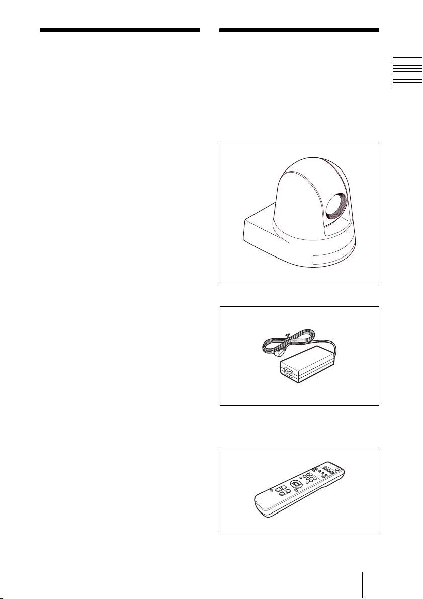
Camera and Supplied Accessories
Overview
When you unpack, check that all the
supplied accessories are included.
Camera (1)
AC power adaptor (1)
AC power cord (1)
Infrared remote commander (1)
Features / Camera and Supplied Accessories
3
Page 4
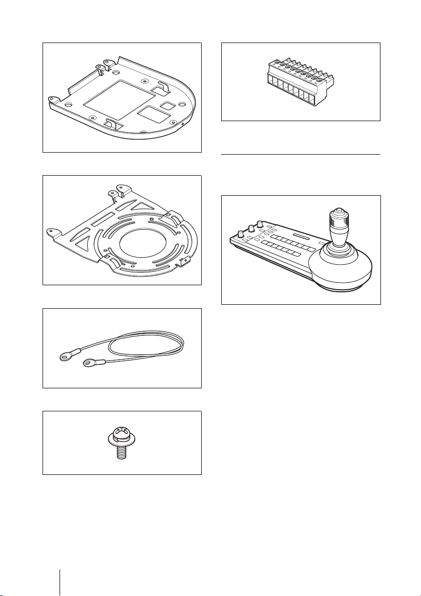
Ceiling bracket (A) (1)
VISCA RS-422 connector plug (1)
Operating Instructions (CD-ROM) (1)
Ceiling bracket (B) (1)
Wire rope (1)
Screw +M 3×8 (8)
Optional Products
RM-IP10 IP Remote Controller
Operate up to 112 cameras that are
compatible with IP connection using the
LAN connection. Up to five RM-IP10 IP
remote controllers can be installed to the
same system.
The joystick of the IP remote controller
allows you comfortable pan/tilt and zoom
operations. The IP remote controller also
allows operation of up to seven cameras by
using the RS-232 connections or RS-422
connections.
Supplied accessories: AC adaptor (1), AC
power cord (1), RS-422 connector plug (2),
CD-ROM (1)
4 Camera and Supplied Accessories
Page 5
System Configuration
The SRG-300H HD Color Video Camera has various system configuration capabilities using
optional products. This section describes three typical system examples with the required
components and the main usage of each system.
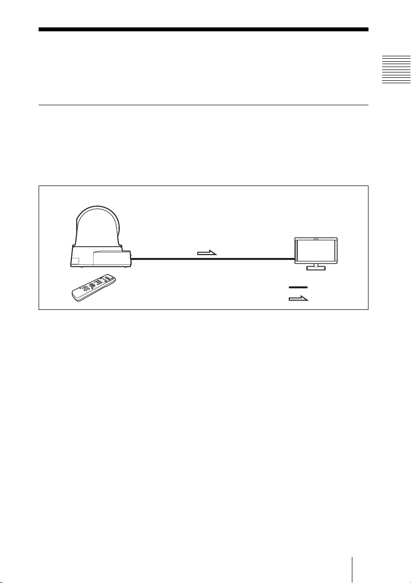
Operating a SRG-300H Camera Using the Supplied Infrared Remote
Commander
This system allows you:
To operate the camera readily from a short distance
System configuration
SRG-300H
HD video monitor
Overview
Infrared Remote Commander
(supplied)
Video signal
Signal flow
System Configuration
5
Page 6
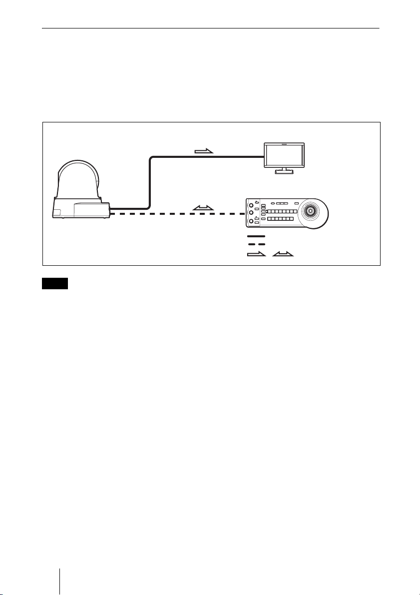
Operating a SRG-300H Camera Using the RM-IP10 IP Remote
Controller
This system allows you:
To perform pan/tilt and zoom operations using the joystick of the IP remote controller, and to
perform the Preset operation using the button.
System configuration
HD video monitor
SRG-300H
RM-IP10 IP Remote Controller
Video signal
Remote Control (VISCA) signal
Signal flow
,
Note
Select the MODE selector of RM-IP10 to position 0 (automatically selected) when using a
combination of SRG-300H and RM-IP10. For details, refer to the Operating Instructions of
RM-IP10.
6 System Configuration
Page 7
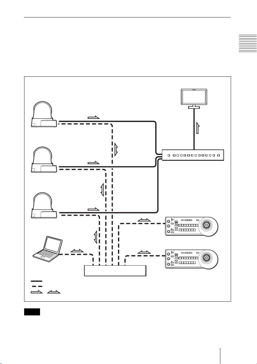
Operating Multiple SRG-300H Cameras Using Multiple IP Remote
Controllers
System configuration
• You can connect up to 112 cameras and five IP remote controllers.
• The joystick of the IP remote controller allows comfortable pan/tilt and zoom operations.
System configuration
HD video monitor
Camera
SRG-300H
Camera
SRG-300H
Video switcher
Camera
SRG-300H
Overview
RM-IP10 IP Remote Controller
PC for the setting
Video signal
Remote control (LAN) signal
Signal flow
,
es
Switching hub
RM-IP10 IP Remote Controller
Note
You cannot use the RS-232 and RS-422 connections when using the LAN connection.
System Configuration
7
Page 8
Location and
34
2 2
Functions of Parts
and Controls
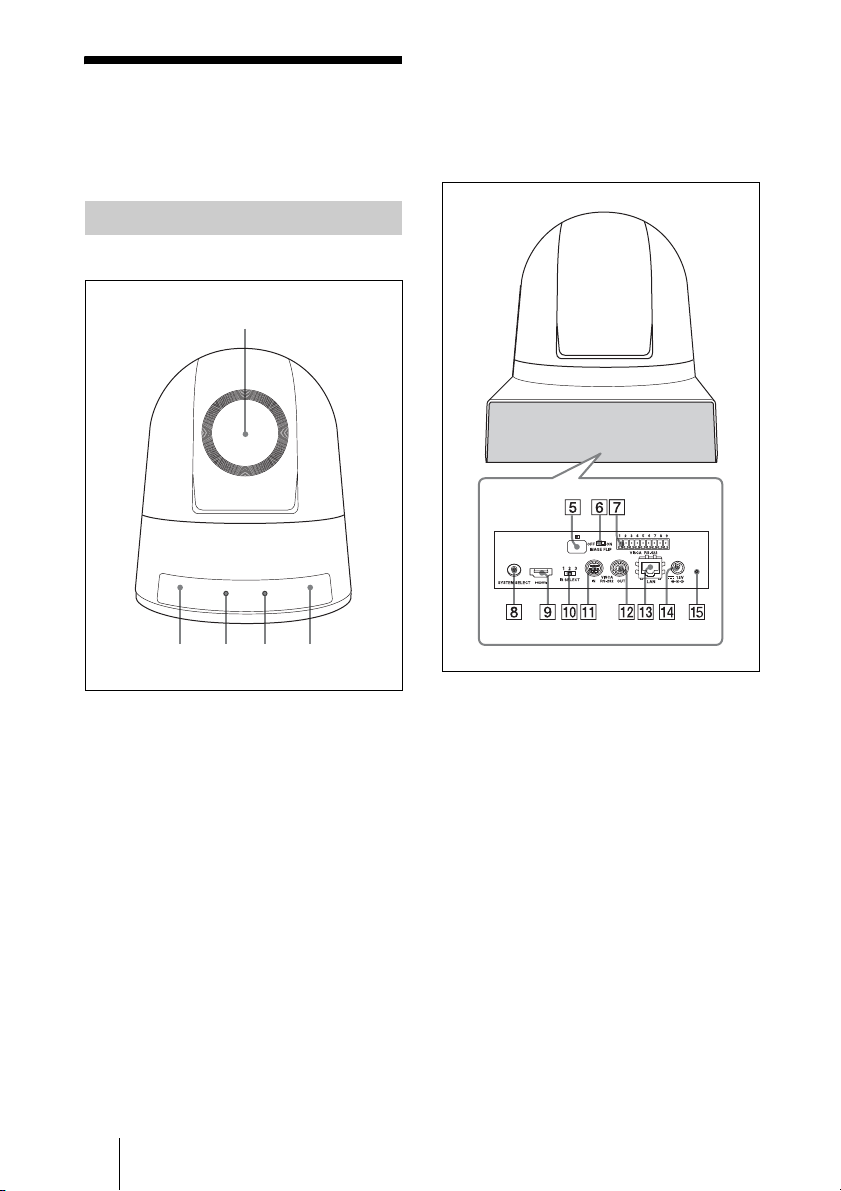
Camera
Front
1
D STANDBY lamp
The orange lamp lights when the camera
is turned off using the infrared remote
commander.
Rear
A Lens
This is a 30-magnification optical zoom
lens.
B Infrared remote commander
sensors
These are sensors for the supplied
infrared remote commander.
C POWER lamp
The green lamp lights when the camera
is connected to an AC outlet using the
supplied AC power adaptor and AC
power cord. It takes about 15 to
30 seconds to display the image after the
lamp lights.
The green lamp flashes when the camera
receives an operation command from the
supplied infrared remote commander.
8 Location and Functions of Parts and Controls
E Infrared remote commander
sensors
These are sensors for the supplied
infrared remote commander.
F IMAGE FLIP switch
Flips the image upside down. Normally
set this to OFF when you use the camera.
When the camera is attached to the
ceiling, set this to ON. Turn off the unit
before setting the IMAGE FLIP switch.
Then, turn the power on by connecting
the power adaptor, by VISCA
CONTROL or the infrared remote
commander. When you switch this, the
preset setting is returned to the initial
setting.
G VISCA RS-422 connector
To communicate via RS-422, use this
connector.
Page 9
Use the supplied VISCA RS-422
connector plug.
H SYSTEM SELECT switch
Used for selecting the video format of
the signal to be output from the HDMI
video connector.
For details, see “Setting of the SYSTEM
SELECT switch” (page 10).
I HDMI video connector
Supplies the images as a HDMI video
signal or DVI video signal.
J IR SELECT switch
Select the camera number when you
operate multiple cameras with the same
infrared remote commander.
K VISCA IN connector
Connect to a computer via an RS-232
interface. When you connect multiple
cameras, connect it to the VISCA OUT
connector of the previous camera in the
daisy chain connection.
L VISCA OUT connector
When you connect multiple cameras,
connect it to the VISCA IN connector of
the next camera in the daisy chain
connection.
O Reset switch
The reset switch is available only when
LAN is set. If you press this switch with
a pointed tip for about five seconds, the
camera will reboot and the IP settings
will return to the factory default.
Factory settings for IP
IP address: 192.168.0.100
Subnet mask: 255.255.255.0
Name: CAM1
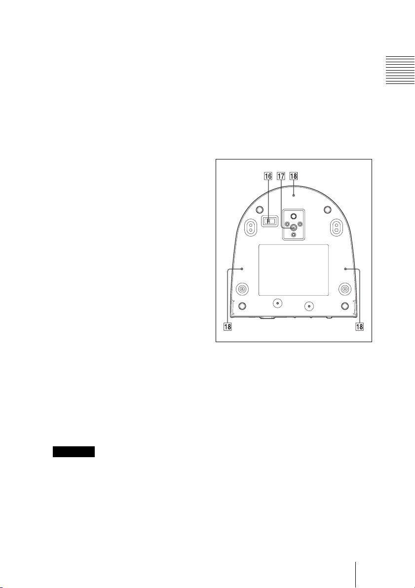
Bottom
Overview
M LAN connector (RJ-45 8-pin)
Connect to a switching HUB that is
compatible with 10BASE-T/100BASETX using a LAN cable (category 5 or
higher, shielded twisted pair).
When a link is established, the green
indicator lights, and it flashes during
communication. While connected with
100BASE-TX, the yellow indicator also
lights.
CAUTION
For safety, do not connect the connector
for peripheral device wiring that might
have excessive voltage to this port.
Follow the instructions for this port.
N DC 12 V connector
Connect the supplied AC power adaptor.
P BOTTOM switches
Used for LAN and VISCA CONTROL
switching, RS-232 and RS-422
switching, 9,600 bps and 38,400 bps
baud rate selection and IR signal output
setting.
For details, refer to the setting of the
BOTTOM switches (page 10).
Q Tripod screw hole
R Ceiling bracket mounting screw
holes
Location and Functions of Parts and Controls
9
Page 10
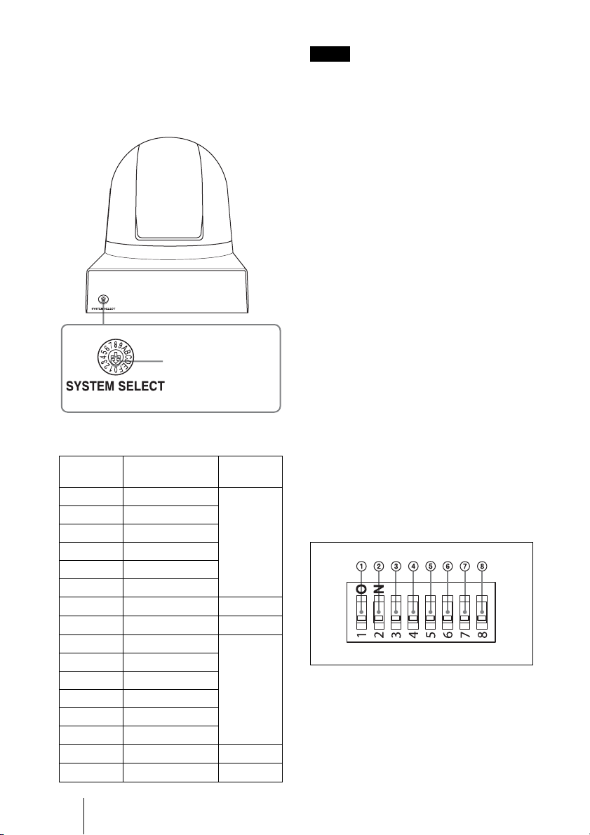
Setting of the SYSTEM SELECT
switch
This switch allows you to select the video
format of the signal to be output from the
HDMI video connector.
SRG-300H
Set this arrow to the
desired video format.
Switch
position
0
1
2
3
4
5
6
7
8
9
A
B
C
D
E
F
Video format
1920×1080p/59.94
No output
1920×1080p/29.97
1920×1080i/59.94
1280×720p/59.94
1280×720p/29.97
EDID
VISCA CONTROL
1920×1080p/50
No output
1920×1080p/25
1920×1080i/50
1280×720p/50
1280×720p/25
No output
No output
59.94 Hz
system
–
–
50 Hz
system
–
–
Notes
• Be sure to set this switch before you turn
on the power of the camera. You can also
set this switch in the standby mode of the
camera. After completing the setting, turn
on the power of the camera by connecting
it to an AC outlet using the supplied AC
power adaptor and AC power cord, by
using the VISCA command or infrared
remote commander.
• Be sure to use a Phillips-head screwdriver
when changing the switch position. If you
use a tool other than the designated
screwdriver, the crossed groove may be
damaged.
• If the switch position is set to 1, 9, E or F
(no output), the POWER lamp and
STANDBY lamp will both remain lit. In
such cases, control via the infrared remote
commander and VISCA commands is
disabled.
• If the switch is set to 6 (EDID), the most
suitable format will be output
automatically based on the resolution of
the TV monitor to be connected.
• If the switch position is set to 7 (VISCA
CONTROL), you can configure the video
format via external communication.
For detailed information, refer to the
Technical Manual of the camera. For details
on obtaining a Technical Manual, consult
your Sony dealer.
Setting of the BOTTOM switches
ON
OFF
OFF: Default position
To change the setting of the BOTTOM
switches, turn off the camera (unless it is in
standby mode) first, set the BOTTOM
switches, then turn on the camera again.
Changing the BOTTOM switches is not
possible while the camera is turned on.
10 Location and Functions of Parts and Controls
Page 11
A VISCA/LAN switch
Select the control setting.
Set to ON to use the LAN connection
and set to OFF to use the VISCA
CONTROL (serial control).
B RS-232/RS-422 select switch
(when using the serial
connection)
Set to RS-422 to operate color video
camera using the VISCA command via
the RS-422 interface.
C BAUD RATE SELECT switch
(when using the serial
connection)
Set the communication speed in the
VISCA CONTROL.
ON: 38,400 bps
OFF: 9,600 bps
D IR OUT switch
Set to ON to enable output of the
receiver signals, which are transmitted
from the infrared remote commander via
the VISCA IN connector (page 47), or
set it to OFF to disable the output.
E Switch 5 (Not used)
Be sure to set this switch to OFF.
F Switch 6 (Not used)
Be sure to set this switch to OFF.
G Switch 7 (Not used)
Be sure to set this switch to OFF.
H Switch 8 (Not used)
Be sure to set this switch to OFF.
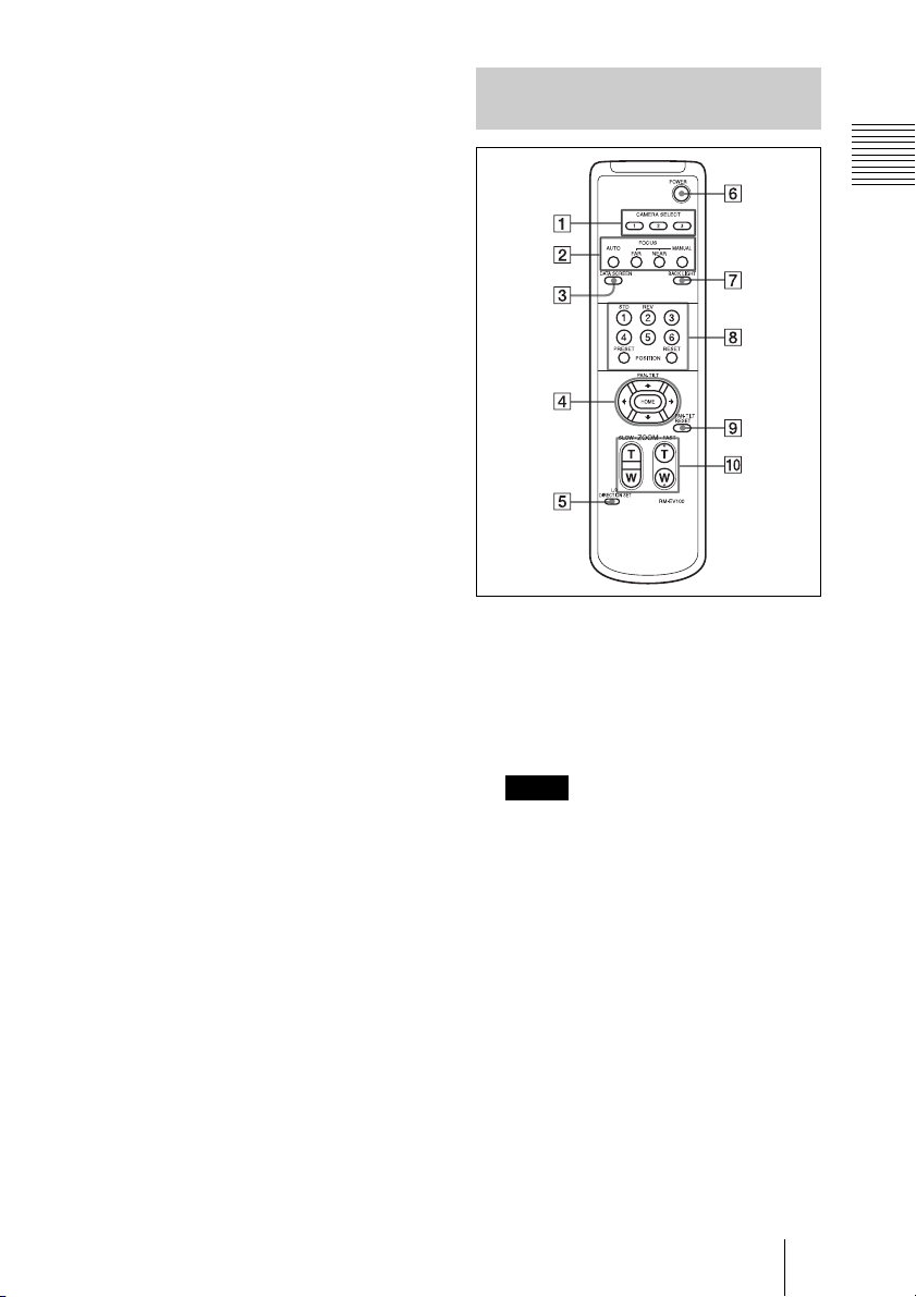
Infrared Remote Commander (supplied)
Overview
A CAMERA SELECT buttons
Press the button corresponding to the
camera you want to operate with the
infrared remote commander.
The camera number can be set using the
IR SELECT switch on the rear of the
camera.
Note
If two or more cameras are adjacent and
have the same camera number, they are
operated simultaneously with the same
infrared remote commander. When you
install the cameras close to each other,
set different camera numbers.
For the camera number setting, see
“Operating Multiple Cameras with the
Infrared Remote Commander”
(page 25).
B FOCUS buttons
Used for focus adjustment.
Press the AUTO button to adjust the
focus automatically. To adjust the focus
manually, press the MANUAL button,
and adjust it with the FAR and NEAR
buttons.
Location and Functions of Parts and Controls
11
Page 12
Note
Press the MANUAL button and adjust
the focus manually when shooting the
following objects.
• White walls and other objects without
contrast
• Objects behind glass
• Objects with horizontal stripes
• Objects on which bright lights are cast
or reflected
• Nightscapes and other dark objects
with blinking lights
• Lit objects shot with darkened
exposure adjustment or exposure
compensation settings
C DATA SCREEN button
Press this button to display the main
menu. Press it again to turn off the menu.
If you press the button when a lowerlevel menu is selected, the display goes
back to a higher-level menu.
Note
Pan/tilt operations are disabled when the
menu is displayed (except PAN/TILT
LIMIT setting).
D PAN-TILT buttons
Press the arrow buttons to adjust the
direction of the camera. Press the HOME
button to face the camera back to the front.
When the menu is displayed, use V or v
to select the menu items and B or b to
change the set values. The selected
setting menu is displayed, by pressing
the HOME button when the main menu
is displayed.
G BACK LIGHT button
Press this button to enable the backlight
compensation. Press it again to disable
the backlight compensation.
H POSITION buttons
Hold down the PRESET button and press
button 1 to 6 to store the current camera
direction, zooming, focus adjustment and
backlight compensation in the memory of
the pressed number button.
To erase the memory contents, hold
down the RESET button and press
button 1 to 6.
Note
These buttons do not function when the
menu is displayed.
I PAN-TILT RESET button
Press this button to reset the pan/tilt
position.
J ZOOM buttons
Use the SLOW button to zoom slowly,
and the FAST button to zoom quickly.
Press the T (telephoto) side of the button
to zoom in, and the W (wide angle) side
to zoom out.
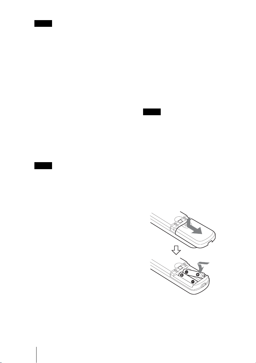
To install batteries
E L/R DIRECTION SET button
Hold down this button and press the REV
button to change the direction of the
camera movement opposite to that
B/b
indicated by the arrow of the
buttons.
To reset the direction of the camera
movement, press the STD button while
holding down this button.
F POWER button
Press this button to turn on/off the
camera when the camera is connected to
an AC outlet.
12 Location and Functions of Parts and Controls
Two R6 (size AA) batteries
(not supplied)
Page 13

CAUTION
Danger of explosion if battery is incorrectly
replaced.
Replace only with the same or equivalent
type recommended by the manufacturer.
When you dispose of the battery, you must
obey the law in the relative area or country.
Installing batteries
Two R6 (size AA) batteries are supplied for
Infrared Remote Commander.
To avoid risk of explosion, use R6 (size AA)
manganese or alkaline batteries.
Overview
Location and Functions of Parts and Controls
13
Page 14
B Adjusting and Setting with Menus
About On-Screen Menus
You can change various settings, such as
shooting conditions and system setup of the
camera, while observing menus displayed
on a connected monitor.
This section explains how to read the onscreen menus before starting menu
operations.
For the overall menu configurations, see
“Menu Configuration” (page 40).
Note
You cannot perform pan/tilt operations
while the menu is displayed.
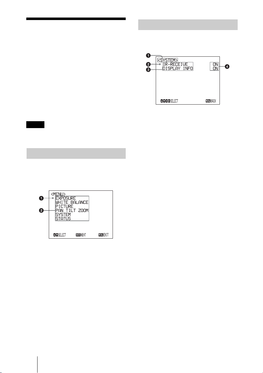
Main Menu
To display the main menu, press the DATA
SCREEN button on the supplied infrared
remote commander.
Setting Menus
The setting menu selected on the main menu
is displayed.
a Setting menu
The name of the setting menu currently
selected is displayed here.
b Selected item
Selects a setting item.
The selected item is shown by the
cursor.
Move the cursor up or down by pressing
the V or v button on the infrared remote
commander.
c Setting items
The setting items for this setting menu
are displayed.
Select the setting item using the V or v
button on the infrared remote
commander.
a Selected item
Selects a setting menu.
The selected item is shown by the
cursor. The cursor moves up or down by
pressing the V or v button on the
infrared remote commander.
b Menu items
To display a setting menu, select one
using the V or v button on the infrared
remote commander and press the
HOME button on the infrared remote
commander.
14 About On-Screen Menus
d Set value
The currently set values are displayed.
To change a set value, use the B or b
button on the infrared remote
commander.
For the default value of each setting
item, see “Menu Configuration”
(page 40).
Page 15
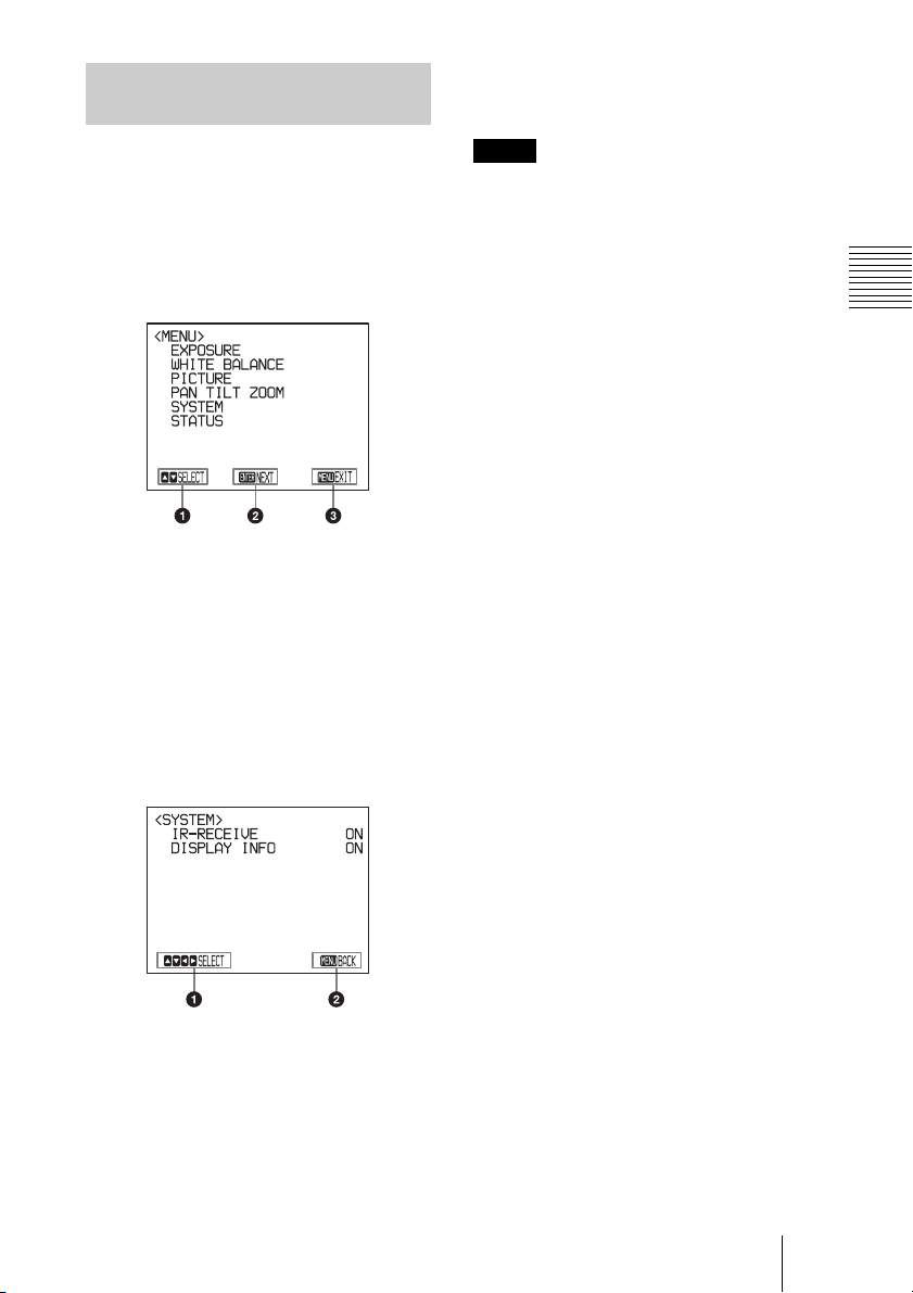
Control Button Display Section
Names of buttons displayed on the monitor
are different from buttons on the infrared
remote commander to be used.
Use the proper buttons on the infrared
remote commander, referring to the
following pictures.
Main menu
a Indicates that you can select a menu item
by V or v button on the infrared remote
commander. The selected item is shown
by the cursor.
b Indicates that you can move to the next
layer by pressing the HOME button.
c Indicates that you can return to the
normal display by pressing the DATA
SCREEN button.
Setting menu
b Indicates that you can return to the main
menu by pressing the DATA SCREEN
button.
Note
When you are operating the menu using the
supplied infrared remote commander, you
cannot set IR-RECEIVE in the SYSTEM
menu to OFF. To set IR-RECEIVE to OFF,
use the appropriate VISCA command.
For detailed information on how to connect
and VISCA command list, refer to the
Technical Manual of the camera. For details
on obtaining a Technical Manual, consult
your Sony dealer.
Adjusting and Setting with Menus
a Indicates that you can select the setting
item by using the V or v button and you
can change the set value by using tthe B
or b button.
About On-Screen Menus
15
Page 16

EXPOSURE Menu
The EXPOSURE menu is used to set the
items related to the exposure.
SPEED: Select the electronic shutter speed
from among the following:
For the 59.94/29.97 video format:
1/1, 1/2, 1/4, 1/8, 1/15, 1/30,
1/60, 1/90, 1/100, 1/125, 1/180, 1/250,
1/350, 1/500, 1/725, 1/1000, 1/1500,
1/2000, 1/3000, 1/4000, 1/6000,
1/10000 sec.
For the 50/25 video format:
1/1, 1/2, 1/3, 1/6, 1/12, 1/25,
1/50, 1/75, 1/100, 1/120, 1/150, 1/215,
1/300, 1/425, 1/600, 1/1000, 1/1250,
1/1750, 1/2500, 1/3500, 1/6000,
1/10000 sec.
MODE (exposure mode)
FULL AUTO: The exposure is adjusted
automatically using the sensitivity,
electronic shutter speed, and iris.
BRIGHT: Adjust the brightness level
(LEVEL) manually.
SHUTTER PRI: Shutter Priority mode.
The exposure is adjusted automatically
using the sensitivity and iris. Adjust the
electronic shutter speed (SPEED)
manually.
IRIS PRI: Iris Priority mode. The exposure
is adjusted automatically using the
sensitivity and electronic shutter speed.
Adjust the iris (IRIS) manually.
MANUAL: Adjust the sensitivity (GAIN),
electronic shutter speed (SPEED) and
iris (IRIS) manually.
When you select one from among the
various exposure modes, some of the
following setting items that are required for
the selected mode appear.
GAIN: Select the gain from among the
following:
0, 3, 6, 9, 12, 15, 18, 21, 24, 27, 30, 33,
36, 39, 43 dB
IRIS: Select the iris from among the
following:
CLOSE, F14, F11, F9.6, F8.0, F6.8,
F5.6, F4.8, F4.0, F3.4, F2.8, F2.4, F2.0,
F1.6
LEVEL: Select the brightness level from
among 0, 5 to 31.
WIDE D (Wide dynamic range mode):
When MODE (exposure mode) is set to
FULL AUTO, the camera distinguishes
light and dark areas in the same scene,
adjusts the brightness for dark areas, and
also controls the blown out highlights.
You can select the wide dynamic range
mode from among OFF, LOW, MID and
HIGH.
Notes
• You can set the wide dynamic range
mode when WIDE D is set to FULL
AUTO only.
• When WIDE D is not set to OFF, the
MODE setting is fixed at FULL
AUTO.
• When changing WIDE D, a change in
screen luminance occurs for a
moment.
• When the change of exposure is big,
the screen may stop for a moment.
GAIN LIMIT: Select the upper limit of the
gain rise in FULL AUTO, SHUTTER
PRI and IRIS PRI modes. Select from
among 9, 12, 15, 18, 21, 24, 27, 30, 33,
36, 39, 43 dB.
16 EXPOSURE Menu
Page 17

EX-COMP (exposure compensation)
When MODE is set to one of FULL AUTO,
SHUTTER PRI or IRIS PRI, set this item to
ON to enable exposure compensation.
When you set EX-COMP to ON, LEVEL
appears and you can select the exposure
compensation level from among the
following:
–7, –6, –5, –4, –3, –2, –1, 0, +1, +2, +3, +4,
+5, +6, +7
If you set the level to 0, exposure
compensation will be disabled. Level +7 is
the brightest and –7 is the darkest
compensation value.
When EX-COMP is set to OFF, exposure
compensation does not function.
SLOW SHUTTER
When you set the mode to ON, the camera
automatically uses slow shutter speed for
exposure as the illumination of the object to
be shot decreases. This mode is only
available when AE mode is set to FULL
AUTO.
WHITE BALANCE Menu
The WHITE BALANCE menu is used to
select the white balance mode.
Adjusting and Setting with Menus
MODE (white balance mode)
Select the white balance mode from among
the following:
AUTO, IN DOOR, OUT DOOR, ONE
PUSH, ATW (Auto Tracing White
Balance), MANUAL
When you select MANUAL, R.GAIN (red
gain) and B. GAIN (blue gain) appear. You
can select each item in the range from –128
to 127.
When you select the ONE PUSH
mode
Perform the following operation.
1 Zoom in on a white subject in the
center of the screen.
2 Press the HOME button of the
supplied infrared remote commander.
The one-push white balance adjustment
is activated.
When DISPLAY INFO (page 20) is set to
ON on the SYSTEM menu, the result of the
white balance adjustment is displayed on the
monitor.
WHITE BALANCE Menu
17
Page 18

PICTURE Menu
The PICTURE menu is used to set the items
related to the picture.
APERTURE (aperture compensation)
Select the aperture compensation level from
among MIN, 1 to 14 and MAX.
HIGH RESOLUTION
You can set this mode to ON or OFF. When
set to ON, you can enjoy emphasised edge
and high-resolution images.
NOISE REDUCTION
You can enjoy clearer images by removing
unnecessary noise (fixed pattern and
randomised noise). You can select 6 levels
from OFF (MIN), 1 to 5 (MAX).
image to stabilize after turning on the
power of the camera.
• Depending on the installation conditions,
the image stabilizer may not be effective.
• When the image stabilizer function is
enabled, the subject appears closer.
• The image stabilizer may not be effective
in an installation environment where high
frequency vibration is present. In this case,
set the image stabilizer function to OFF.
IMAGE STABILIZER
You can select this function according to the
shooting conditions.
OFF: The image stabilizer function does not
operate.
ON: The image stabilizer function operates.
When set to ON, you can obtain steadier
images if vibration is present. This stabilizer
is effective for vibration frequencies around
10 Hz. This function utilizes digital zoom;
therefore, the angle of view and resolution of
images may be affected. However, image
sensitivity is retained.
Notes
• The image stabilizer function is not
effective during pan/tilt operations. It may
take some time for the image to stabilize
after performing pan/tilt operations.
• If the image stabilizer function is already
enabled, it may take some time for the
18 PICTURE Menu
Page 19

PAN TILT ZOOM Menu
The PAN TILT ZOOM menu is used to
select the pan/tilt/zoom mode.
PAN/TILT LIMIT
When you set PAN/TILT LIMIT to ON, you
can select the limit of pan/tilt operation.
You can select the following values:
RIGHT: +170° to –169°, selectable in 1°
steps.
LEFT: +169° to –170°, selectable in 1°
steps.
UP: +90° to –19° (IMAGE FLIP:OFF)
+20° to –89° (IMAGE FLIP:ON)
selectable in 1° steps.
DOWN: +89° to –20° (IMAGE FLIP:OFF)
+19° to –90° (IMAGE FLIP:ON)
selectable in 1° steps.
Note
The indicated value is changed when the B
or b button is released. When the pan/tilt
function is in motion, the indicated value
does not change.
Setting the range of LEFT/RIGHT
movement
(IMAGE FLIP : OFF)
CENTER (0°)
–170° +170°
Adjusting and Setting with Menus
Note
The limit of pan/tilt operation becomes
effective promptly after you set the range of
PAN/TILT LIMIT. When you want to make
the camera start with the ranges set, before
turning off the power, store those values in
POSITION 1.
For details, see “Storing the Camera
Settings in Memory — the Presetting
Feature” (page 26).
Setting the range of UP/DOWN
movement
(IMAGE FLIP : OFF)
+90°
0°
–20°
Note
When you turn the camera to the right or left
beyond the 100° with the camera pointed
downward by 20°, the camera may be caught
on the lens, depending on the zoom position
of the lens.
PAN TILT ZOOM Menu
19
Page 20

PAN/TILT SLOW mode
When you set this function to ON, the PAN/
TILT operation becomes slow. This makes it
easier for the camera to capture a slow
moving subject.
D-ZOOM (digital zoom)
You can set digital zoom to ON or OFF.
When set to OFF, digital zoom does not
operate, and only optical zoom is available.
When set to ON, digital zoom takes over
after optical zoom reaches MAX (×30). Up
to ×360 can be zoomed digitally.
When digital zoom is available, the
resolution decreases.
SYSTEM Menu
IR-RECEIVE (infrared signal
reception)
When this is set to OFF, the camera does not
receive the signal from the supplied infrared
remote commander.
Be sure to keep it set to ON when you use the
supplied infrared remote commander.
Note
You cannot set IR-RECEIVE to OFF when
you operate the menu using the supplied
infrared remote commander. To set it to
OFF, use the appropriate VISCA command.
DISPLAY INFO
When this item is set to ON, the message
automatically appears for about 3 seconds
on the monitor screen, when you perform the
following operations using the supplied
infrared remote commander.
20 SYSTEM Menu
Message Remote control
PRESET n: OK
“n” is a preset
position number of
the infrared remote
commander,
between 1 and 6.
RECALL n: OK
“n” is a preset
position number of
the infrared remote
commander,
between 1 and 6.
operation
You have stored the
camera settings to
POSITION 1 to 6.
You have read the
camera settings stored
in POSITION 1 to 6.
Page 21

Message Remote control
RESET n: OK
“n” is a preset
position number of
the infrared remote
commander,
between 1 and 6.
ONE PUSH WB: OPDuring the white
ONE PUSH WB: OKWhen white balance
ONE PUSH WB: NGIf white balance
Note
operation
You have reset the
camera settings stored
in POSITION 1 to 6 to
the default settings.
balance adjustment in
the ONE PUSH white
balance mode, the
message blinks on the
screen.
adjustment is correctly
performed in ONE
PUSH white balance
mode, this message
appears on the screen.
adjustment is
incorrectly performed
in ONE PUSH white
balance mode, this
message flashes on the
screen.
The operations in the VISCA CONTROL
and LAN connection are from n: 1 to 16.
VIDEO MODE
The setting of the HDMI and DVI are
available when the video is output from the
HDMI video connector.
When the SYSTEM SELECT is set to
EDID, the video mode cannot be set.
COLOR SYSTEM
The setting of the YCbCr and RGB are
available for color space of the video image.
When the SYSTEM SELECT is set to
EDID, the color system cannot be set.
STATUS Menu
The STATUS menu is used to display the
settings selected with the menus.
Adjusting and Setting with Menus
The STATUS menu consists of PAGE1 to
PAGE5.
This menu only displays the current menu
settings, and you cannot change them with
this menu.
PAGE1: Shows the settings selected with
the EXPOSURE menu.
PAGE2: Shows the settings selected with
the PICTURE menu and the WHITE
BALANCE menu.
PAGE3: Shows the settings selected with
the PAN TILT ZOOM menu.
PAGE4: Shows the settings selected with
the SYSTEM menu, supplied infrared
remote commander channel, VISCA
communication baud rate, VIDEO
mode, Color system and Video latency
setting.
PAGE5: Shows the settings selected with
the LAN connection with IP address,
Subnet mask and MAC address (shows
when the BOTTOM switch is set to
LAN only).
Note
The VISCA communication baud rate and
the VIDEO mode for the camera are
displayed. Even if you change the settings
after turning on the power, those settings are
ignored and are not changed on the display.
For detailed information on the Video
latency setting, refer to the Technical
Manual of the camera.
STATUS Menu
21
Page 22

B Operation Using the Supplied Infrared Remote Commander
Before Operating
Before operating the camera, check that the
camera and peripheral devices are properly
installed and connected.
For details, see “Setting of the SYSTEM
SELECT switch” (page 10), “Installing the
Camera” (page 28) and “Connections”
(page 32).
Note
The supplied infrared remote commander
may not work correctly near the inverter
lighting fixtures. In such a case, try to install
the camera far from the inverted luminaire.
You can check whether or not the installed
location is good for the usage of the infrared
remote commander.
For detailed information on how to check,
refer to the Technical Manual. For details
on obtaining a Technical Manual, consult
your Sony dealer.
Turning on the Power
SRG-300H
DC 12 V
to AC outlet
22 Before Operating / Turning on the Power
POWER lights.
1 Connect the camera to an AC outlet
using the supplied AC power adaptor
and power cord.
The power is turned on and the POWER
lamp lights.
The camera will automatically pan and
tilt and be reset to the position stored in
POSITION 1 (Pan/tilt reset action).
Page 23

2 Turn on the peripheral devices.
To turn on/off the camera using the
infrared remote commander
As long as the camera is connected to an AC
outlet, you can turn the camera on or off with
the POWER switch on the infrared remote
commander.
When you turn the power off using the
infrared remote commander, the POWER
lamp turns off and the STANDBY lamp
lights on the camera.
POWER
The STANDBY
lamp lights.
Pan/Tilt and Zoom Operation
Panning and Tilting
Operation Using the Supplied Infrared Remote Commander
1 Press the POWER switch.
The camera will turn on and perform the
pan/tilt reset operation automatically.
2 Press the arrow button to pan or tilt the
camera.
While checking the picture on the
screen, press the desired arrow button.
To move the camera little by little,
press the button just for a moment.
To move the camera in a wide range,
press and hold the button.
To move the camera diagonally, press
the B or b button while holding down
the V or v button.
To face the camera back to the front
Press the HOME button.
If the camera moves in a different
direction from the one you intended
The camera is preset so that the image output
from the camera is rotated toward the right
whenever you press the b button.
Pan/Tilt and Zoom Operation
23
Page 24

To face the camera toward the
opposite direction
You might wish to face the camera toward
the opposite direction from that of the button
you pressed, for example, when you change
the direction of the camera while checking
the picture on the screen. In such a case,
press the 2 (REV) button while holding
down the L/R DIRECTION SET button.
Arrow
button
Movement of
the camera
Setting
When the STANDBY lamp is blinking
While
holding down
Press
To reset the setting
To reset the setting, press the 1 (STD) button
while holding down the L/R DIRECTION
SET button.
Arrow
button
Note
Movement of
the camera
Setting
While
holding down
Press
The setting above only changes the signal
emitted from the infrared remote
commander, and does not change the setting
of the camera itself. Therefore, repeat the
setting for each infrared remote commander
if you are using more than one infrared
remote commander.
The STANDBY lamp blinks.
If the camera is moved forcibly, or a finger
or other object interferes with camera
movement, the camera may fail to memorize
the pan/tilt position.
Press the PAN-TILT RESET button to reset
the pan/tilt position.
Zooming
Press either of the ZOOM buttons.
Subject appears
closer. (Telephoto)
Subject appears
farther away.
(Wide angle)
Zooms in or out
fast (FAST side)
Zooms in or out
slowly (SLOW side)
Note
When you perform pan/tilt operation while
the camera is in the telephoto mode, the
moving speed of the image on the screen
may be a little jerky.
24 Pan/Tilt and Zoom Operation
Page 25

Operating Multiple Cameras with the Infrared Remote Commander
1 Set the IR SELECT switch on the rear
of the camera you want to operate to 1,
2 or 3.
2 Press the CAMERA SELECT button
on the infrared remote commander
that corresponds to the number set in
step 1.
Adjusting the Camera
Operation Using the Supplied Infrared Remote Commander
CAMERA
SELECT
Then, you can operate the camera(s)
specified by number. Every time you operate
the camera(s) using the infrared remote
commander, the CAMERA SELECT button
pressed in step 2 lights.
Focusing on a Subject
Focusing the camera on a subject
automatically
Press the AUTO button.
The camera focuses on the subject at the
center of the screen automatically.
Focusing the camera on a subject
manually
After pressing the MANUAL button, press
either the FAR or the NEAR button to have
the camera focus on the subject.
Focusing on a far
subject
Focusing on a
near subject
Adjusting the Camera
25
Page 26

Shooting with Back Lighting
When you shoot a subject with a light source
behind it, the subject becomes dark. In such
a case, press the BACK LIGHT button.
To cancel the function, press the BACK
LIGHT button again.
Storing the Camera
Settings in Memory
— the Presetting
Feature
Up to 16 combinations of settings (16
positions) including camera position,
zooming, focusing, and backlighting, can be
preset.
Subject
appears
brighter.
Note
The BACK LIGHT function is effective if
MODE is set to FULL AUTO in the
EXPOSURE menu of the camera.
For details of the camera settings to be
preset, see “Preset Items” (page 43).
1 Press the PAN-TILT RESET button to
reset the pan/tilt position.
2 Adjust the position, zooming,
focusing and backlighting of the
camera (page 23 to page 26).
3 While holding down the PRESET
button, press any of the POSITION
buttons, 1 to 6, in which you want to
store the settings.
26 Storing the Camera Settings in Memory — the Presetting Feature
Page 27

Press a POSITION
button.
While holding
down this button
When you set DISPLAY INFO (page
20)
to ON on the SYSTEM menu, the
message “PRESET n : OK”
automatically appears for about 3
seconds on the monitor screen.
Recalling the stored settings
Press any of the POSITION buttons, 1 to 6,
in which you have stored the settings. The
message “RECALL n:OK” automatically
appears for about 3 seconds on the monitor
screen.
Cancelling the preset memory
While holding down the RESET button,
press the POSITION button from which you
want to cancel the settings.
up, store or cancel the settings in another
POSITION.
• When the menu is displayed on the screen,
you cannot perform the operation for
storing, recalling, or cancelling the setting.
Be sure to return to the normal display
before starting these operations.
Operation Using the Supplied Infrared Remote Commander
Press a
POSITION button.
While holding
down this button
When you set DISPLAY INFO (
page 20) to
ON on the SYSTEM menu, the message
“RESET n : OK” automatically appears for
about 3 seconds on the monitor screen.
Notes
• When the power is turned on, the camera
starts with the settings stored in
POSITION 1.
• If you want to retain the previous pan and
tilt positions, etc. before the power is
turned off and turned on again, store those
positions in POSITION 1.
• When you are storing or cancelling the
settings in one POSITION, you cannot call
Storing the Camera Settings in Memory — the Presetting Feature
27
Page 28

B Installation and Connection
Installing the Camera
Installing the Camera on a Desk
Place the camera on a flat surface.
If you have to place the camera on an
inclined surface, make sure that the
inclination is less than ±15 degrees to
guarantee pan/tilt performance, and take
measures to prevent it from falling.
Notes
• Do not grasp the camera head when
carrying the camera.
• Do not turn the camera head by hand.
Doing so may result in a camera
malfunction.
Attaching the Camera to a Tripod
Attach a tripod to the screw hole used for
attaching a tripod on the bottom of the
camera.
The tripod must be set up on a flat surface
and its screws tightened firmly by hand.
Use a tripod with screws of the following
specifications.
4 = 4.5 to 7 mm
4 = 0.18 to 0.22 inches
Caution
Installation of the camera using the
tripod screws and screw holes should not
be done for installation on a ceiling or a
shelf, etc., in a high position.
Installing the Camera Using the M3 Fixing Screw Holes
Attach the camera using 3 M3 fixing screw
holes located on the bottom of the camera.
Attach the camera to a fitting with a flat
surface using M3 screws with the following
specifications.
M3 screw
28 Installing the Camera
4 = 3 to 8 mm
4 = 1/8 to 11/32 inches
Page 29

Installing the unit on the ceiling
Using the ceiling bracket, wire rope, and
retaining screws supplied, you can utilize
existing junction boxes, etc., to attach the
camera to the ceiling.
When you install the unit, always install it on
a level ceiling. If you have to install it on a
sloping or uneven ceiling, make sure that the
place where you install it is within ±15
degrees of the horizontal.
CAUTION
• Entrust installation to an experienced
contractor or installer when installing the
unit on ceilings or other high locations.
• When installing the unit in a high location,
be sure that the location and installation
components (excluding the supplied
accessories) are strong enough to support
the unit and the mounting bracket, and
install the unit securely. If the components
are not strong enough, the unit may fall
and cause serious injury.
• Always install the supplied wire rope to
prevent the unit from falling.
• If you install the unit in a high location,
check periodically, at least once a year, to
ensure that the connection has not
loosened. If conditions warrant, make this
periodic check more frequently.
Installation
1 Set the IMAGE FLIP switch on the
rear panel to ON.
Notes
• Make sure that the BOTTOM switch is
set to the correct position. See “Setting
of the BOTTOM switches” (page 10).
• If you set the IMAGE FLIP switch to
ON after turning on the power, the
image will not be flipped. Turn the
power off once, then on again, and the
image will be flipped. It takes about 15
to 30 seconds to display the image.
• When you toggle the IMAGE FLIP
switch, the pre-set settings will all be
returned to the initial settings.
2 Attach the wire rope to the junction
box in the ceiling.
Use a screw hole and a screw (not
supplied) in the junction box to attach
the wire rope.
Ceiling
Installation and Connection
Before installation
After deciding the direction in which the
camera will shoot, make the required holes
for the junction box, and connecting cables.
Note
The connecting cables cannot be passed
through ceiling bracket (A). A hole for the
wiring is required in the ceiling at the back
of the unit where it is attached to the ceiling.
Hole for connecting cable
Installing the Camera
29
Page 30

2-2 If the wire cannot be attached to the
junction box, attach to the position
on the ceiling bracket (B) in the
illustration.
3 Attach the ceiling bracket (B) to the
junction box on the ceiling.
Align the holes in the bracket with those
in the junction box, and use appropriate
screws (not supplied).
There are elongated holes for the screws
along the rounded edges of the ceiling
bracket (B). Later, the front of the
camera will be positioned along this
edge. Face the camera to the front, adjust
the aim, and attach it securely.
Ceiling
30 Installing the Camera
Ceiling
bracket (B)
Front of the camera
Page 31

4 Attach the ceiling bracket (A) to the
bottom of the camera using the 3
screws (M 3
Align the screw holes on the bottom of
the camera with those in the ceiling
bracket, and attach the bracket to the
camera.
Attach
the wire rope.
× 8
M 3
(supplied)
3
1
× 8) supplied.
Ceiling
2
Ceiling
bracket (A)
5 Insert the protrusions raised on the
ceiling bracket (A) into the spaces
prepared in the ceiling bracket (B),
and temporarily attach them by
pushing the ceiling bracket (A) to the
rear.
Ceiling
bracket
(B)
Ceiling
Ceiling
bracket (A)
6 While pushing up on the front part of
the camera, attach it using the 3 screws
× 8) supplied, starting with the
(M 3
screw at position 1.
Installation and Connection
Tighten the screws a bit at a time in the
numbered order shown in the illustration.
After all of the screws are inserted and
temporarily tightened properly, securely
tighten each one in turn.
Note
For assembly, use only the screws supplied
with the unit. Using other screws may
damage the unit.
Ceiling
1
M 3 × 8
(supplied)
Installing the Camera
31
Page 32

7 Connect the cables to the connectors
on the rear of the camera.
Ceiling
Connections
Connecting to an AC Outlet
Use the supplied AC power adaptor and AC
power cord to connect the camera to an AC
outlet.
SRG-300H
Notes
• Take the proper steps to ensure that the
load of the cables connected does not
cause problems.
• To prevent the HDMI cable
disconnecting from the camera (either
by its own weight or an external
force), it is recommended to secure it
with commercially available retaining
parts, etc.
Removing the camera
1 Remove the 3 screws used to attach
the camera in step 6 of “Installation.”
2 While pushing the entire camera up
towards the ceiling, move the camera
to the front.
The hooks will disengage, and you can
remove the camera.
to AC
outlet
DC 12 V
AC power adaptor
(supplied)
AC power cord (supplied)
32 Connections
Page 33

Connecting a Computer
RS-232 Connections
SRG-300H
• Do not mix VISCA RS-232 (cross) and
VISCA RS-422 cables. Using these cables
at the same time may result in
malfunction. Cannot be used in the LAN
connection.
To obtain a cable, consult your Sony dealer.
For detailed information on how to connect
the camera and the VISCA command list,
refer to the Technical Manual of the camera.
For details on obtaining a Technical
Manual, consult your Sony dealer.
RS-422 Connections
SRG-300H
VISCA IN
Computer
Notes
to the AC power
adaptor (supplied)
VISCA cable
(not supplied)
to RS-232 input
• When you connect a computer to the
camera using the VISCA cable (RS-232
cross cable), you can control the camera
from a computer instead of the supplied
infrared remote commander.
• In the case of VISCA RS-232 connection,
make sure that the BOTTOM switch is set
to RS-232 (page 10).
• It is not possible to connect both VISCA
RS-232 and VISCA RS-422
simultaneously.
VISCA OUT
VISCA RS-422
connector plug
(supplied)
Computer
Notes
to the AC power
adaptor (supplied)
VISCA
RS-422 cable
RS-422 to RS-232
converter (not
supplied)
to RS-232 input
• Make up the cable using the supplied
VISCA RS-422 connector plug. See
“Using the VISCA RS-422 connector pin
assignments” (page 47).
• In the case of VISCA RS-422 connection,
make sure that the BOTTOM switch is set
to RS-422 (page 10).
Installation and Connection
Connections
33
Page 34

• It is not possible to connect both VISCA
RS-232 and VISCA RS-422
simultaneously.
• Do not mix VISCA RS-232 (cross) and
VISCA RS-422 cables. Using these cables
at the same time may result in
malfunction. Cannot be used in the LAN
connection.
LAN connection
SRG-300H
to the AC power
adaptor
(supplied)
LAN cable
(not supplied)
• Use a LAN cable that is compatible with
10BASE-T/100BASE-TX (category 5 or
higher, shielded twisted pair) for this
connection.
Connecting the RM-IP10 IP Remote Controller
Use the RS-232 connecting cable supplied
with the IP remote controller.
SRG-300H
to the AC
VISCA
RS-232
IN
RS-232 cable
(supplied with
the RM-IP10)
power
adaptor
(supplied)
Computer
Notes
• In the case of a LAN connection, make
sure that the BOTTOM switch of the
camera is set for LAN connection
(page 10).
• Dedicated application software is needed.
For details about the application software,
consult your Sony dealer.
34 Connections
VISCA RS-232
LAN
RM-IP10 IP
Remote Controller
MODE
DC IN 12V
RS-422
RS-232C
VISCA
1919
to the AC power
adaptor (supplied
with the RM-IP10)
TALLY/ CO NTACT
!
DC 12V
Note
When using the VISCA RS-232 connectors,
check that the BOTTOM switch on the
bottom of the camera (page 10) and the
BOTTOM switch on the bottom of the IP
remote controller are set to RS-232.
Page 35

To connect the IP Remote
Controller using the VISCA RS-422
connectors
You can use the VISCA RS-422 connectors
to connect the RM-IP10 IP remote controller
to the camera instead of the VISCA RS-232
connectors. Use of the VISCA RS-422
connectors allows the connection up to
1,200 m (3,937 feet) away.
Prepare the connecting cable using the RS422 connector plugs that come with the
camera and the IP remote controller.
For making the cable, refer to “Using the
VISCA RS-422 connector pin assignments”
on pages 47, 48.
SRG-300H
• When the connections using the VISCA
RS-422 connectors are made, the VISCA
RS-232 connection is not available.
LAN connection
SRG-300H
to the AC
power adaptor
(supplied)
LAN cable
(not supplied)
Installation and Connection
VISCA
RS-422
to the AC
power adaptor
(supplied)
VISCA
RS-422 cable
VISCA RS-422
LAN
MODE
RM-IP10 IP Remote
Controller
RS-422
RS-232C
VISCA
1919
TALLY/CO NTACT
!
DC 12V
to the AC power
adaptor
(supplied with
the RM-IP10)
Notes
• When using the VISCA RS-422
connectors, check that the BOTTOM
switch on the bottom of the camera
(page 10) and the BOTTOM switch on the
bottom of the IP remote controller are set
to RS-422.
LAN
MODE
RM-IP10 IP Remote
Controller
RS-422
RS-232C
VISCA
1919
TALLY/CO NTACT
!
DC 12V
to the AC
power adaptor
(supplied with
the RM-IP10)
Notes
• In case of LAN connection, make sure that
the BOTTOM switch of the camera is set
for LAN connection (page 10).
• Use a LAN cable that is compatible with
10BASE-T/100BASE-TX (category 5 or
higher, shielded twisted pair) for this
connection.
• Use the crossover cable if you want to
connect directly to the LAN connector of
one camera and one IP remote controller
without using a switching hub.
Connections
35
Page 36

Connecting a Video Monitor, etc., Equipped with HDMI Input Connector
SRG-300H
HDMI video
connector
HDMI cable
(not supplied)
to HDMI input
connector
HD video monitor, etc.
Notes
to the AC
power adaptor
(supplied)
• Configure the, VIDEO FORMAT, based
on the specifications of the HD monitor.
• Depending on the performance
capabilities of the HDMI cable, some
picture noise may occur. For the HDMI
cable, a Sony high-speed cable is
recommended.
• If the volume of the monitor is set to
maximum, a sound m ay emit for a moment
when activated, depending on the product.
This is not a malfunction.
• It takes about 15 to 30 seconds to display
the image.
• To prevent the HDMI cable disconnecting
from the camera (either by its own weight
or an external force), it is recommended to
secure it with commercially available
retaining parts, etc.
36 Connections
Page 37

B Appendix
Message List
The following messages and indications may appear for this camera. Perform the following as
necessary.
Lamp display
Lamp Meaning and solution
The STANDBY lamp and
POWER lamp are lit.
The STANDBY lamp is lit. If the camera is moved forcibly, or a finger or other object interferes
Screen display
Message Meaning and solution
PRESET n:OK
(“n” is a preset position
number between 1 and 16)
RECALL n:OK
(“n” is a preset position
number between 1 and 16)
RESET n:OK
(“n” is a reset position
number between 1 and 16)
ONE PUSH WB:OP During the white balance adjustment in the ONE PUSH white
ONE PUSH WB:OK When the white balance adjustment has been done correctly in the
ONE PUSH WB:NG When the white balance adjustment has failed in the ONE PUSH
The SYSTEM SELECT switch is set to “no output” (page 10).
with camera movement, the camera’s built-in processor may fail to
memorize the pan/tilt position.
Press the PAN-TILT RESET button to reset the pan/tilt position.
This message appears for about 3 seconds when you store camera
settings to POSITION 1 to 16.
The preset position number of the infrared remote commander is
POSITION 1 to 6.
This message appears for about 3 seconds when you read the camera
settings stored in POSITION 1 to 16.
The preset position number of the infrared remote commander is
POSITION 1 to 6.
This message appears for about 3 seconds when you reset camera
settings stored in POSITION 1 to 16.
The preset position number of the infrared remote commander is
POSITION 1 to 6.
balance mode, this message blinks on the screen.
ONE PUSH white balance mode, this message is lit on the screen.
white balance mode, this message blinks on the screen.
Appendix
Message List
37
Page 38

Troubleshooting
Before bringing in your camera for service, check the following as a guide to troubleshooting
the problem. If the problem cannot be corrected, consult your Sony dealer.
Symptom Cause Remedy
The power of the camera is
not turned on.
The picture is not
displayed on the video
monitor connected to the
camera.
Pan, tilt, or zoom cannot be
operated.
The EXPOSURE menu
cannot be set except for
FULL AUTO.
The infrared remote
commander does not work.
The VISCA CONTROL is
not available with a
computer connected to the
camera.
The AC power adaptor is not
connected to the DC 12 V
connector firmly.
The AC power cord is not
inserted firmly into the AC
power adaptor or the AC outlet.
The video cable is not connected
properly.
The exposure is not set correctly
on the camera.
The SYSTEM SELECT switch
on the rear of the camera is not
set correctly.
A menu is displayed on the
monitor screen.
The panning or tilting range is
limited.
WIDE D is not set to OFF. After setting the WIDE D to
The CAMERA SELECT button
you pressed on the infrared
remote commander does not
match the number set with the IR
SELECT switch on the camera.
The computer is not correctly
connected to the camera.
Insert the power cord firmly as
far as it will go.
Insert the power cord firmly as
far as it will go.
Check the connection between
the camera and video monitor.
Set the exposure correctly on the
EXPOSURE menu (page 16).
Check the selected output signal
format of the camera and the
input signal format of the
connected monitor.
Press the DATA SCREEN button
on the supplied infrared remote
commander to remove the menu
from the monitor screen.
Change the PAN/TILT LIMIT
setting on the PAN TILT ZOOM
menu (page 19).
OFF, select the MODE of the
EXPOSURE (page 16).
Press the CAMERA SELECT
button corresponding to the IR
SELECT switch setting on the
camera (page 25).
Make sure the connection
between the computer and
camera is made correctly.
Check that the baud rate setting
(9,600 bps or 38,400 bps) is
properly made with the
BOTTOM switch on the bottom
of the camera (page 10).
Check that the SYSTEM
SELECT switch (page 10) is set
to a position in which video
signals are output.
38 Troubleshooting
Page 39

Symptom Cause Remedy
LAN communication is not
available with a computer
connected to the camera.
The computer is not correctly
connected to the camera.
Make sure the connection
between the computer and
camera is made correctly.
Check that the VISCA/LAN
switch (BOTTOM switch) is set
to ON (page 10).
The computer is not correctly set. Check the precautions in the
setting of the dedicated PC
application.
The camera does not work
when connec ted one-to-one
A crossover cable is not used. Use a crossover cable for one-to-
one LAN connection.
to the IP remote controller.
The camera cannot be
operated at all.
- Pull out the plug of the power
cord from the AC outlet, then
reinsert it into the AC outlet after
waiting a while.
Check that the BOTTOM
switches 5, 6, 7 and 8 are set to
OFF.
Appendix
Troubleshooting
39
Page 40

Menu Configuration
The menus of the camera are configured as described below. For more details, refer to the pages
in parentheses.
The initial settings of each item are in bold.
(See page 16.)
40 Menu Configuration
Page 41

(See page 17.)
(See page 18.)
(See page 19.)
(See page 20.)
Appendix
Menu Configuration
41
Page 42

(See
page 21.)
42 Menu Configuration
Page 43

Preset Items
The following items set by using the infrared remote commander and menu items can be stored
in the memory of the camera.
Items adjusted with the infrared remote commander
Preset item Preset position number
12 to 16
Pan/Tilt Position
Zoom Position
Focus Mode Auto/Manual
Focus Position
Backlight Compensation ON/OFF
Menu items
Preset item Preset position number
EXPOSURE MODE
WIDE D z a
SLOW SHUTTER z –
AE GAIN LIMIT z –
BRIGHT LEVEL z a
SPEED z a
IRIS z a
GAIN z a
EX-COMP ON/OFF z a
EX-COMP LEVEL z a
WHITE BALANCE MODE z a
ONE PUSH WB R/B Data z –
MANUAL R/B GAIN z a
APERTURE z a
PICTURE EFFECT z a
HIGH RESOLUTION z a
NOISE REDUCTION z a
PAN/TILT LIMIT z –
D-ZOOM z a
DISPLAY INFO z –
z :Setting items retained in memory when the power is turned off and then on again. The
camera starts with these settings stored in POSITION 1.
a :Setting items retained in memory when the power is turned off and then on again.
– :Setting items cleared from the memory when the power is turned off and then on and reset
to the initial settings.
z
z
z
z
z
1
z a
2 to 16
a
a
a
a
a
Appendix
Preset Items
43
Page 44

For detailed information on POSITION 1, see “Storing the Camera Settings in Memory
— the Presetting Feature” (page 26).
You can store the following items in the memory (POSITION 1), but you can set them only by
using the appropriate VISCA command.
• Focus Near Limit
• IR Receive
• IR Receive Return
For detailed information on the VISCA command list, refer to the Technical Manual of the
camera. For details on obtaining a Technical Manual, consult your Sony dealer.
The setting of preset numbers 1 to 16 are available for VISCA CONTROL and LAN
connection.
44 Preset Items
Page 45

Specifications
System
Video signal 1920×1080p/59.94
1920×1080p/29.97
1920×1080i/59.94
1280×720p/59.94
1280×720p/29.97
1920×1080p/50
1920×1080p/25
1920×1080i/50
1280×720p/50
1280×720p/25
EDID
VISCA CONTROL
(switched with the SYSTEM
SELECT switch)
Synchronization
Internal synchronization
Image device 1/2.8 type Exmor CMOS
Lens 30× (optical), 12× (digital)
f = 4.3 mm (wide) to 129 mm (tele)
F1.6 to 4.7
Horizontal angle: 65 degrees
(WIDE end)
Minimum object distance
10 mm (13/32 inche) (WIDE end)
to 1200 mm (47 1/4 inches)
(TELE end)
Minimum illumination
1.4 lux (F1.6, 50 IRE, highsensitivity mode OFF, 30fps)
2.8 lux (F1.6, 50 IRE, highsensitivity mode OFF, 60fps)
0.35 lux (F1.6, 50 IRE, highsensitivity mode ON, 30fps)
0.7 lux (F1.6, 50 IRE, highsensitivity mode ON, 60fps)
Shutter speed 1/1 to 1/10000 sec. (22 steps)
Video S/N 50 dB
Pan/tilt action Horizontal: ±170 degrees
Maximum panning speed:
100 degrees/sec.
Vertical: +90, –20 degrees
(IMAGE FLIP: OFF)
+20, –90 degrees (IMAGE
FLIP: ON)
Maximum tilting speed:
90 degrees/sec.
Input/output connectors
HDMI (HDMI connector)
Control input/output
VISCA IN: Mini DIN 8-pin type,
RS-232
VISCA OUT: Mini DIN 8-pin
type, RS-232
VISCA RS-422: 9-pin
LAN connector: RJ-45 (8-pin),
10BASE-T/100BASE-TX auto
discrimination
Power connector
JEITA type4 (DC 12 V)
General
Input voltage 12 V DC (10.8 to 13.2 V DC)
Power consumption
16.8 W
Operating temperature
0 ºC to +40 ºC (+32 ºF to +104 ºF)
Storage temperature
–20 ºC to +60 ºC (–4 ºF to +140 ºF)
Dimensions Video camera: 157 × 164 × 163
mm (6 1/4 × 6 1/2 × 6 1/2
inches) (w/h/d)
Infrared Remote Commander:
56 × 26 × 210 mm (2 1/4 ×
1 1/16 × 8 3/8 inches) (w/h/d)
Installation angle
Less than ±15 degrees to the
horizontal surface
Supplied accessories
AC power adaptor
AC power cord (1)
Infrared Remote Commander (1)
Ceiling bracket (A) (1)
Ceiling bracket (B) (1)
Wire rope (1)
Screw M3×8 (8)
VISCA RS-422 connector plug (1)
Safety Regulations (1)
Operating Instructions (CD-ROM) (1)
Design and specifications are subject to
change without notice.
The terms HDMI and HDMI High-Definition
Multimedia Interface, and the HDMI Logo are
trademarks or registered trademarks of HDMI
Licensing LLC in the United States and other
countries.
Appendix
Specifications
45
Page 46

Dimensions
Top Back
170°
170°
Front Side
90
°
164 (6 29/64)
104 (4 3/32)
Bottom
42 (1 21/32)
29.5 (1 5/32)
Ø 5, depth5
A
42 (1 21/32)
28 (1 7/64)
64 (2 33/64) 64 (2 33/64)
31 (1 7/32)
M3
46 Specifications
A
63.5 (2 1/2) 63.5 (2 1/2)
157 (6 3/16)
42 (1 21/32)
M3
A
1/4-20UNC, depth7
Tripod screw hole
42 (1 21/32)
14 (35/64)
20 (25/32)
77 (3 1/32)
M3
4-Ø 8 (A)
(Leg)
20°
164 (6 29/64)
72 (2 53/64)
163 (6 27/64)
Unit: mm (inches)
Page 47

Pin assignments
VISCA IN connector (mini-DIN 8-pin,
female)
Using the VISCA RS-422 connector pin assignments
The VISCA RS-422 connector pin
assignments
Pin No. Function
1DTR IN
2DSR IN
3 TXD IN
4 GND
5 RXD IN
6 GND
7 IR OUT L*
8 IR OUT R*
* The IR OUT function of pins 7 and 8 are
selectable with the BOTTOM switch on
the bottom of the camera.
VISCA OUT connector (mini DIN 8pin, female)
12345
6789
VISCA RS-422
Pin No. Function
1 TXD IN+
2 TXD IN–
3 RXD IN+
4 RXD IN–
5 GND
6 TXD OUT+
7 TXD OUT–
8 RXD OUT+
9 RXD OUT–
Using the VISCA RS-422 connector
plug
1 Insert a wire (AW G Nos. 28 to 18)
into the desired wire opening on the
supplied VISCA RS-422 connector
plug, and tighten the screw for that
wire using a flat-head screwdriver.
Appendix
Pin No. Function
1 DTR OUT
2 DSR OUT
3 TXD OUT
4 GND
5 RXD OUT
6 GND
7 No connection
8 No connection
Wire
Flat-head screwdriver
Specifications
47
Page 48

2 Insert the VISCA RS-422 connector
plug into the VISCA RS-422
connector on the rear of the camera.
12
3
4
56
78
9
License
This software partially supports component
uIP. Therefore the following license
conditions apply.
Copyright (c) 2001-2006, Adam Dunkels
and the Swedish Institute of Computer
Science All rights reserved.
Redistribution and use in source and binary
forms, with or without modification, are
permitted provided that the following
conditions are met:
Notes
• In order to stabilize the voltage level
of the signal, connect both ends to
GND.
• Do not make a VISCA RS-232
connection when there is already an
existing VISCA RS-422 connection.
1. Redistributions of source code must
retain the above copyright notice, this list
of conditions and the following
disclaimer.
2. Redistributions in binary form must
reproduce the above copyright notice,
this list of conditions and the following
disclaimer in the documentation and/or
other materials provided with the
distribution.
3. The name of the author may not be used
to endorse or promote products derived
from this software without specific prior
written permission.
THIS SOFTWARE IS PROVIDED BY
THE AUTHOR 'AS IS' AND ANY
EXPRESS OR IMPLIED WARRANTIES,
INCLUDING, BUT NOT LIMITED TO,
THE IMPLIED WARRANTIES OF
MERCHANTABILITY AND FITNESS
FOR A PARTICULAR PURPOSE ARE
DISCLAIMED. IN NO EVENT SHALL
THE AUTHOR BE LIABLE FOR ANY
DIRECT, INDIRECT, INCIDENTAL,
SPECIAL, EXEMPLARY, OR
CONSEQUENTIAL DAMAGES
(INCLUDING, BUT NOT LIMITED TO,
PROCUREMENT OF SUBSTITUTE
GOODS OR SERVICES; LOSS OF USE,
DATA, OR PROFITS; OR BUSINESS
INTERRUPTION) HOWEVER CAUSED
AND ON ANY THEORY OF LIABILITY,
WHETHER IN CONTRACT, STRICT
LIABILITY, OR TORT (INCLUDING
NEGLIGENCE OR OTHERWISE)
ARISING IN ANY WAY OUT OF THE
USE OF THIS SOFTWARE, EVEN IF
ADVISED OF THE POSSIBILITY OF
SUCH DAMAGE.
48 License
Page 49

Sony Corporation
 Loading...