

Page 1
A-ES7-100-11(1)
HD Color Video Camera
Technical Manual
SRG-120DH
2013 Sony Corporation
Page 2

Table of Contents
Features ............................................................................. 3
Connection ........................................................................ 4
System Configuration ...................................................... 5
Locations of Controls .......................................................7
Basic Functions ...............................................................10
Overview of Functions .................................................................. 10
Initial Settings and Preset ............................................................ 16
Mode Condition .............................................................................. 17
Command List .................................................................22
VISCA RS-232 Commands ............................................................ 22
IP Related Setting Command ..................................................... 32
SRG-120DH Commands ............................................................... 34
Specifications ................................................................. 50
Precautions .....................................................................54
2
Page 3

The 1/2.8 type Exmor CMOS camera (utilising
approximately 2 million valid pixels) allows for highdefinition shooting with superior picture quality.
Adopts the zoom lens capable of shooting a wide
range of 71 degree horizontal angle of view with the
12x optical zoom.
By adopting its wide and dynamic range functions,
you can see the optimised shooting image which
incorporates bright and dark subjects at the same
time.
Adopts the industry standard RS-232 interface of
VISCA camera protocol in external communication.
You can use the camera in multi-purpose usages with
the pan/tilt functions of high-speed and high noise
reduction.
You can use the infrared remote commander to set
the camera and also to select panning, tilting and
zooming from the setting menu.
You can store up to 16 kinds of camera direction and
camera status into the camera. In the case of the
infrared remote commander, 6 kinds can be stored.
You can use the LAN cable for external
communication. This will make system construction
easier.
The camera can be set for a variety of HD video
formats and has an HDMI interface terminal. The
HDMI video interface is in widespread use.
Features
3
Page 4
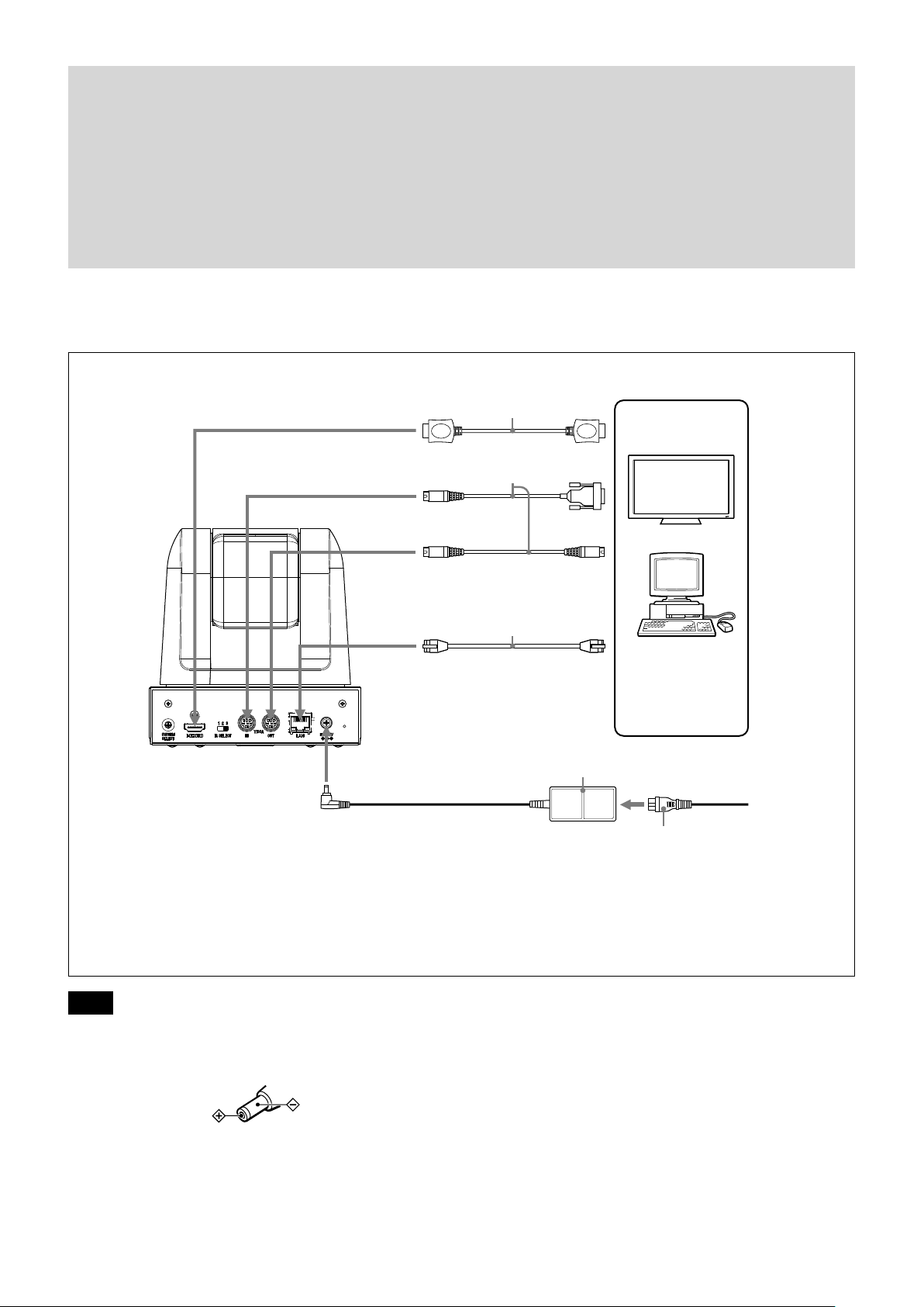
Connection
HDMI cable (not supplied)
to HDMI VIDEO to HDMI input
VISCA cable (not supplied)
1)
to 12V
to VISCA RS-232 IN
to VISCA RS-232 OUT
LAN cable (not supplied)
to LAN to LAN
To VISCA IN of other
SRG series (when
connecting to more
than one camera)
to RS-232
2)
Computer with LAN or
serial communication
interface, HD video
monitor with HDMI
input interface, etc.
AC power adaptor (supplied)
to AC outlet
Power cord (supplied)
1) When the camera is connected to a computer with a VISCA cable (cross type, RS-232), you can operate the
camera with the computer. To obtain a cable, consult the dealer where you bought your camera.
2) For details on the LAN connection using LAN cable, see page 28.
Notes
Use only the AC power adaptor (JEITA type4)
supplied with the unit. Do not use any other AC
power adaptor.
Polarity of the plug
You have to set the video format of the signal to be
output from the camera. For detailed information on
how to set the video format, see “
SYSTEM
SELECT switch” on page 7.
4
Page 5
System Configuration
The SRG-120DH has various system configuration capabilities using optional products. This section describes
three typical system examples with the required components and the main usage of each system.
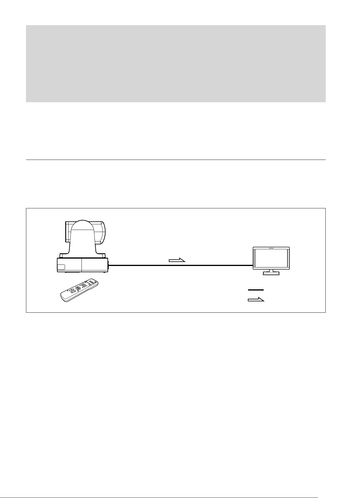
Operating a SRG-120DH Using the Supplied Infrared Remote Commander
This system allows you:
To operate the camera readily from a short distance
System configuration
SRG-120DH
HD video monitor
Infrared Remote Commander
(supplied)
Video signal
Signal flow
5
Page 6
System Configuration
,
Operating a SRG-120DH Using the RM-IP10 IP Remote Controller
This system allows you:
To perform pan/tilt and zoom operations using the joystick of the IP remote controller, and to perform the Preset
operation using the button.
System configuration
HD video monitor
SRG-120DH
RM-IP10 IP Remote Controller
Video signal
Remote Control (VISCA or LAN) signal
Signal flow
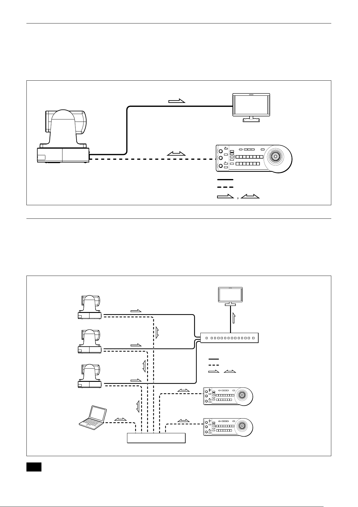
Operating Multiple SRG-120DH Using Multiple RM-IP10 IP Remote Controllers
System configuration
• You can operate up to 112 cameras using five IP remote controllers.
• The joystick of the IP remote controller allows comfortable pan/tilt and zoom operations.
System configuration
HD video monitor
SRG-120DH
SRG-120DH
SRG-120DH
Video switcher
Video signal
Remote control (LAN) signal
Signal flow
PC for the setting
Note
You cannot use the RS-232 connection when using the LAN connection.
Switching hub
RM-IP10 IP Remote Controller
RM-IP10 IP Remote Controller
6
Page 7
Camera
Locations of Controls
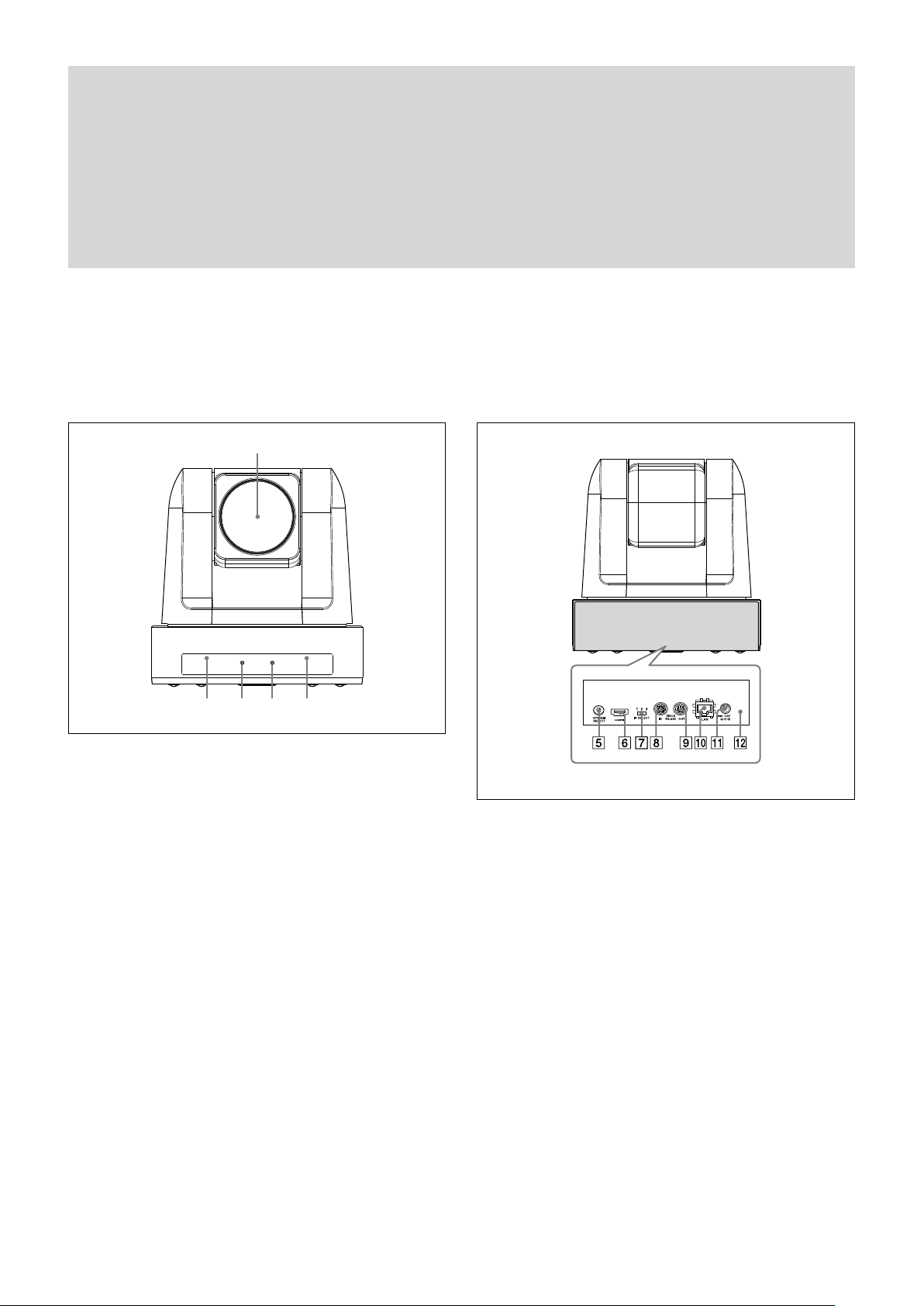
Front
Lens
This is a 12-magnification optical zoom lens.
Infrared remote commander sensors
These are sensors for the supplied infrared remote
commander.
POWER lamp
Lights in green when the camera is connected to an AC
outlet using the supplied AC power adaptor and AC power
cord.
Flashes in green when the camera receives an operation
command from the supplied infrared remote commander.
When the power is turned on, it takes about 15 to 30
seconds to display the image after the lamp lights.
STANDBY lamp
Lights in amber when the power is turned off using the
infrared remote commander.
Rear
SYSTEM SELECT switch
Used for setting the video format of the signal to be output
from the HDMI VIDEO connectors.
For details, see “Setting of the SYSTEM SELECT switch” (page
8).
HDMI video connector
Supplies the images as a HDMI video signal or DVI video
signal.
IR SELECT switch
Select the camera number when you operate multiple
cameras with the same infrared remote commander.
VISCA IN connector
Connect to a computer via an RS-232 interface. When you
connect multiple cameras, connect it to the VISCA OUT
connector of the previous camera in the daisy chain
connection.
7
Page 8
Locations of Controls
8
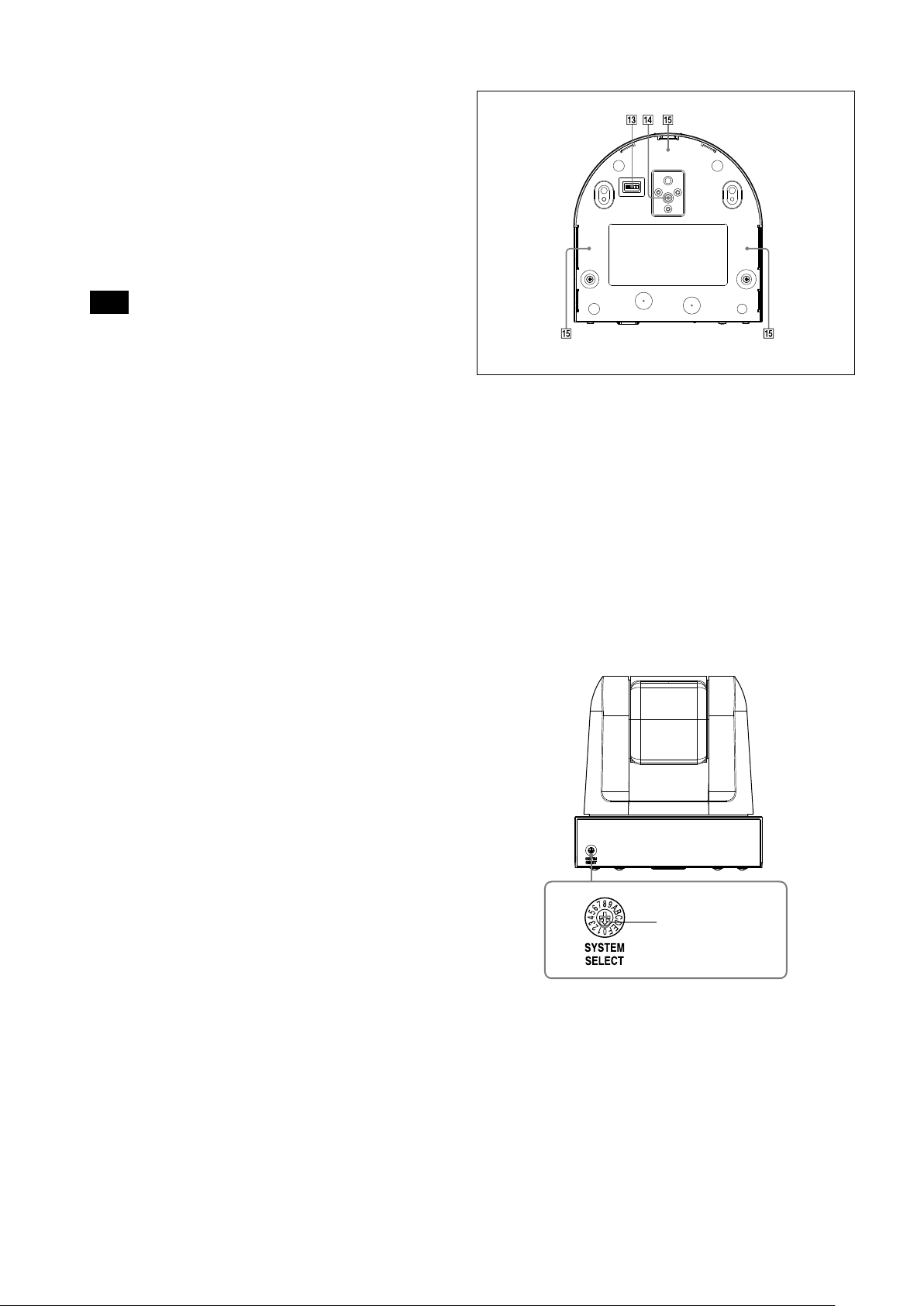
VISCA OUT connector
When you connect multiple cameras, connect it to the
VISCA IN connector of the next camera in the daisy chain
connection.
LAN connector (RJ-45 8-pin)
Connect to a switching HUB that is compatible with
10BASE-T/100BASE-TX using a LAN cable (category 5 or
higher, shielded twisted pair).
When a link is established, the green indicator lights, and it
flashes during communication. While connected with
100BASE-TX, the yellow indicator also lights.
Note
For safety, when connecting the peripheral device, do not
connect the connector that might have excessive voltage to this
connector. Follow the Operating Instructions for the
connection.
12 V connector
Connect the supplied AC power adaptor.
Reset switch
The reset switch is enabled only when the BOTTOM switch
is set to the LAN connection. When you press down this
switch with a pointed tip for about five seconds, the camera
will reboot and only the setting relating to the IP will return
to the factory setting.
Factory settings for IP
IP address: 192.168.0.100
Subnet mask: 255.255.255.0
Name: CAM1
Bottom
BOTTOM switches
Used for LAN and VISCA CONTROL switching, 9,600 bps
and 38,400 bps baud rate selection and IR signal output
setting.
For details, refer to the setting of the BOTTOM switches
(page 9).
Tripod screw hole
Fix-mounting screw holes
Setting of the SYSTEM SELECT switch
This switch allows you to select the video format of the
signal to be output from the HDMI video connector.
SRG-120DH
Set this arrow to the
desired video format.
Page 9
Locations of Controls
Switch position Video format
0 1920×1080p/59.94 59.94 Hz system
1 No output
2 1920×1080p/29.97
3 1920×1080i/59.94
4 1280×720p/59.94
5 1280×720p/29.97
6 EDID —
7 VISCA CONTROL —
8 1920×1080p/50 50 Hz system
9 No output
A 1920×1080p/25
B 1920×1080i/50
C 1280×720p/50
D 1280×720p/25
E No output —
F No output —
Notes
Be sure to set this switch before you turn on the power of the
camera. You can also set this switch in the standby mode of the
camera. After completing the setting, turn on the power of the
camera by connecting it to an AC outlet using the supplied AC
power adaptor and AC power cord, by using the VISCA
command or infrared remote commander.
Be sure to use a Phillips-head screwdriver when changing the
switch position. If you use a tool other than the designated
screwdriver, the crossed groove may be damaged.
If the switch position is set to 1, 9, E and F (no output), the
POWER lamp and STANDBY lamp will both remain lit. In such
cases, control via the infrared remote commander and VISCA
communication is disabled.
If the switch position is set to 6 (EDID), the most suitable format
will be output automatically based on the resolution of the Video
monitor to be connected.
If the switch position is set to 7 (VISCA CONTROL), you can
configure the video format via external communication.
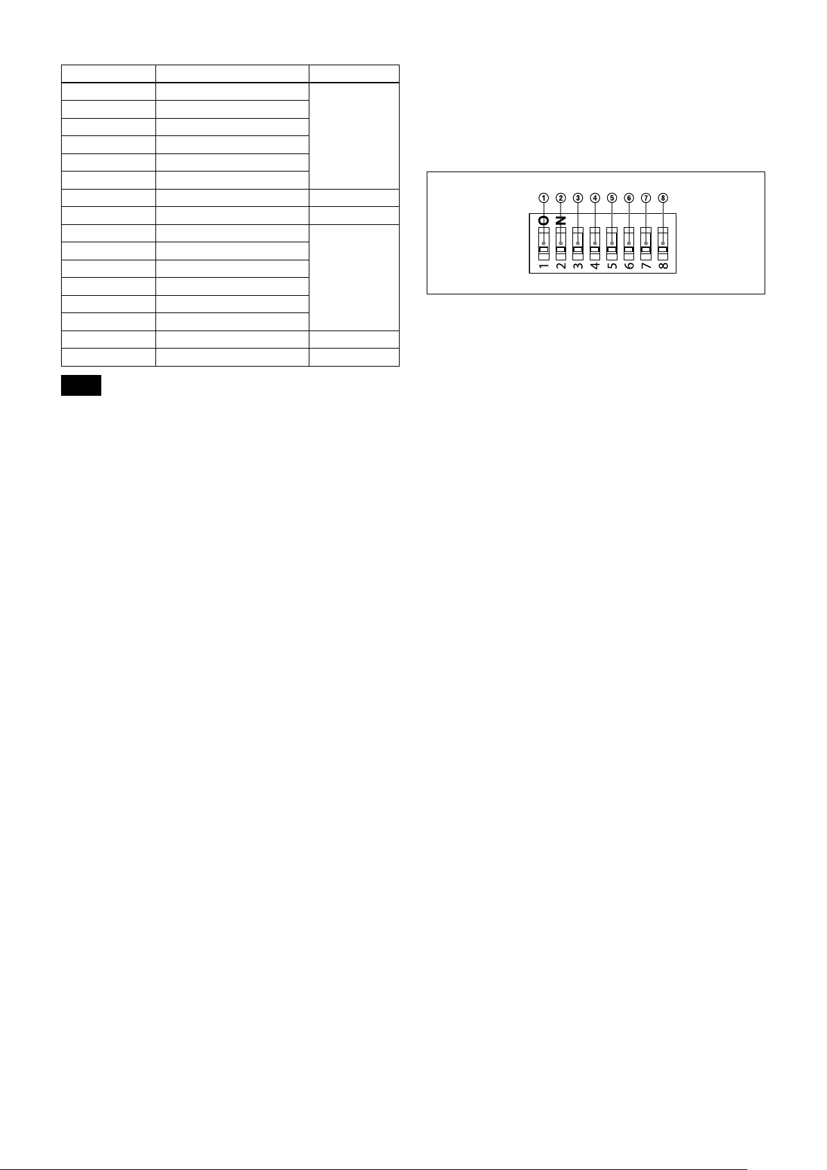
Setting of the BOTTOM switches
To change the BOTTOM switch setting, select the
BOTTOM switch with the power of this unit turned off
(not including standby state), and then turn on the DC
power. The setting cannot be changed after the power
is turned on.
ON
OFF
(Initial position)
VISCA/LAN switch
Select the communication method setting.
Set to ON to use the LAN connection and set to OFF to use
the VISCA CONTROL (serial control).
Switch 2 (Not used)
Be sure to set this switch to OFF.
Baud rate select switch (when using the serial
connection)
Set the communication speed in the VISCA CONTROL.
ON: 38,400 bps
OFF: 9,600 bps
IR OUT switch
Set to ON to enable output of the receiver signals, which are
transmitted from the infrared remote commander via the
VISCA IN connector (page 53), or set it to OFF to disable
the output.
Switch 5 (Not used)
Be sure to set this switch to OFF.
Switch 6 (Not used)
Be sure to set this switch to OFF.
Switch 7 (Not used)
Be sure to set this switch to OFF.
Switch 8 (Not used)
Be sure to set this switch to OFF.
9
Page 10

Basic Functions
Basic Functions
Overview of Functions
Zoom
The SRG camera employs a 12× optical zoom lens
combined with a digital zoom function; this camera
allows you to zoom up to 144×.
• Optical 12
(F 1.8 to F 2.0)
Digital Zoom enlarges the center of the subject by
expanding each image in both the vertical and
horizontal directions. When the digital zoom is used,
the resolution deteriorates.
You can activate the zoom in the following modes, all
of which can be set using VISCA command.
Standard Mode
Variable Mode
There are eight levels of zoom speed.
In these standard and variable modes, it is necessary to send
Stop Command to stop the zoom operation.
Direct Mode
Setting the zoom position enables quick
movement to the designated position.
Digital Zoom ON/OFF
×, f = 3.9 mm to 46.8 mm
Focus
Focus has the following modes, all of which can be set
using VISCA Commands.
• Auto Focus Mode
The Auto Focus (AF) function automatically adjusts
the focus position to maximise the high frequency
content of the picture in a center measurement area,
taking into consideration the high luminance and
strong contrast components.
The minimum focus distance is 10 mm at the optical
wide end and 1500 mm at the optical tele end.
- Normal AF Mode
This is the normal mode for AF operations.
- Interval AF Mode
The mode used for AF movements carried out at
particular intervals. The time intervals for AF
movements and for the timing of the stops can be
set in one-second increments using the Set Time
Command. The initial value for both is set to five
seconds.
- Zoom Trigger Mode
When the zoom is changed, the AF mode activates
for the pre-set time. Then, it stops. The initial
value is set to 5 seconds.
AF sensitivity can be set to either Normal or Low.
- Normal
Reaches the highest focus speed quickly. Use this
when shooting a subject that moves frequently.
Usually, this is the most appropriate mode.
- Low
Improves the stability of the focus. When the
lighting level is low, the AF function does not take
effect, even though the brightness varies,
contributing to a stable image.
10
Page 11

Basic Functions
• Manual Focus Mode
Manual Focus has both a Standard Mode and a
Variable Mode. Standard Mode focuses at a fixed rate
of speed. Variable Mode has eight speed levels that
can be set using a VISCA Command.
In these standard and variable modes, it is necessary to send Stop
Command to stop the zoom operation.
• One Push Trigger Mode
When a Trigger Command is sent, the lens moves to
adjust the focus for the subject. The focus lens then
holds that position until the next Trigger Command is
input.
• Infinity Mode
The lens is forcibly moved to a position suitable for an
unlimited distance.
• Near Limit Mode
Can be set in a range from 1000 (∞) to E000 (1 cm).
Default setting: C500 (10 cm)
White Balance
White Balance has the following modes.
• Auto White Balance
This mode computes the white balance value output
using color information from the entire screen. It
outputs the proper value using the color temperature
radiating from a black subject based on a range of
values from 2500K to 7500K.
This mode is the factory setting.
Automatic Exposure Mode
A variety of AE functions are available for optimal
output of subjects in lighting conditions that range
from low to high.
• Full Auto
Iris, Gain and Shutter Speed can be set automatically.
• Gain Limit Setting
The gain limit can be set at the Full Auto, Shutter
Priority, Iris Priority, Bright and Manual in the AE
mode. Use this setting when image signal-to-noise
ratio is particularly important.
• Shutter Priority
Variable Shutter Speed, Auto Iris and Gain
(1/1 to 1/10,000 sec., 16 high-speed shutter speeds
plus 6 low-speed shutter speeds)
1) Flicker can be eliminated by setting shutter to
1/100s for NTSC models used in countries with a 50 Hz
power supply frequency
1/120s for PAL models used in countries with a 60 Hz power
supply frequency
• Iris Priority
Variable Iris (F1.8 to Close, 14 steps), Auto Gain and
Shutter speed
• Manual
Variable Shutter, Iris and Gain
• Bright
Variable Iris and Gain (Close to F1.8, 14 steps and
F1.8 at 15 steps)
1)
• ATW
Auto Tracing White balance (2000K to 10000K)
• Indoor
3200K Base Mode
• Outdoor
5800K Base Mode
• One Push WB
One Push White Balance is a function that forcibly
captures the white color once the lighting conditions
to illuminate the subject are set, enabling you to shoot
the image in the conditions as they are set. By using
this function, the natural color of the subject can be
obtained without being affected by the surrounding
lighting conditions. To set this mode, shoot the
subject that you want to capture the white color and
send the One Push White Balance Trigger.
The One Push White Balance data is lost when the
power is turned off. If the power is turned off, set One
Push White Balance again.
• Manual WB
Manual control of R and B gain, 256 steps each
AE – Shutter priority
The shutter speed can be set freely by the user to a total
of 22 steps – 16 high speeds and 6 low speeds. When
the slow shutter is set, the speed can be adjusted the
slow shutter according to subject brightness. The
picture output is read at a low rate from the memory.
AF capability is low.
In high speed mode, the shutter speed can be set up to
1/10,000s. The iris and gain are set automatically,
according to the brightness of the subject.
11
Page 12
Basic Functions
MIN
MAX
AGC
CLOSE
OPEN
IRIS
Parameter 59.94/29.97
mode
15 1/10000 1/10000
14 1/6000 1/6000
13 1/4000 1/3500
12 1/3000 1/2500
11 1/2000 1/1750
10 1/1500 1/1250
0F 1/1000 1/1000
0E 1/725 1/600
0D 1/500 1/425
0C 1/350 1/300
0B 1/250 1/215
0A 1/180 1/150
09 1/125 1/120
08 1/100 1/100
07 1/90 1/75
06 1/60 1/50
05 1/30 1/25
04 1/15 1/12
03 1/8 1/6
02 1/4 1/3
01 1/2 1/2
00 1/1 1/1
50/25 mode
AE – Iris priority
The iris can be set freely by the user to 14 steps
between F1.8 and Close.
The gain and shutter speed are set automatically,
according to the brightness of the subject.
Parameter
11 F1.8 0A F5.6
10 F2 09 F6.8
0F F2.4 08 F8
0E F2.8 07 F9.6
0D F3.4 06 F11
0C F4 05 F14
0B F4.8 00 CLOSE
Setting value
Parameter
Setting value
AE – Manual
The shutter speed (22 steps), iris (14 steps) and gain
(15 steps) can be set freely by the user.
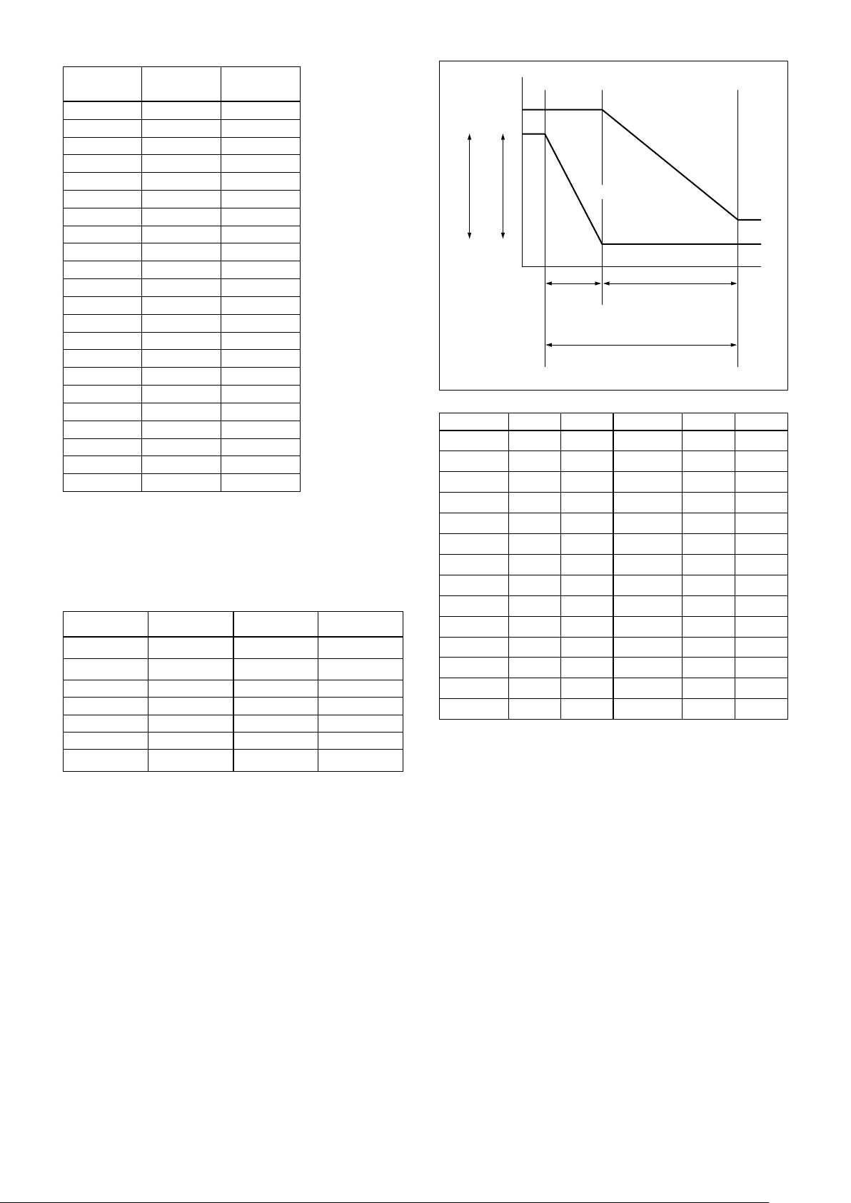
AE – Bright
The bright control function adjusts both gain and iris
using an internal algorithm, according to a brightness
level freely set by the user. Exposure is controlled by
gain when dark, and by iris when bright.
As both gain and iris are fixed, this mode is used when
exposing at a fixed camera sensitivity. When switching
from Full Auto or Shutter Priority Mode to Bright
Mode, the current status will be retained for a short
period of time.
Only when the AE mode is set to “Full Auto” or
“Shutter Priority,” you can switch it to “Bright.”
Gain
IRIS curve
Gain curve
Dark Bright
Controlled
by gain
Bright limit which controllable
for this unit
Parameter Iris Gain Parameter Iris Gain
1F F1.8
1E F1.8
1D F1.8
1C F1.8
1B F1.8
1A F1.8
19 F1.8
18 F1.8
17 F1.8
16 F1.8
15 F1.8
14 F1.8
13 F1.8
12 F1.8
+43 dB
+39 dB
+36 dB
+33 dB
+30 dB
+27 dB
+24 dB
+21 dB
+18 dB
+15 dB
+12 dB
+9 dB
+6 dB
+3 dB
Controlled by IRIS
11 F1.8
10 F2
0F F2.4
0E F2.8
0D F3.4
0C F4
0B F4.8
0A F5.6
09 F6.8
08 F8
07 F9.6
06 F11
05 F14
00 CLOSE
0
dB
0
dB
0
dB
0
dB
0
dB
0
dB
0
dB
0
dB
0
dB
0
dB
0
dB
0
dB
0
dB
0
dB
When switching from the Shutter Priority mode to the
Bright mode, the shutter speed set in the Shutter
Priority mode is maintained.
Defog mode
When the surrounding area of the subject is foggy and
low contrast, the defog mode will make the subject
appear clearer.
12
Page 13

Basic Functions
Wide Dynamic Range Mode (WD)
The Wide Dynamic Range mode is a function for
dividing an image into several blocks and correcting
blocked-up shadows and blown-out highlights in
accordance with the intensity difference. It enables you
to obtain images in which portions ranging from dark
to light can be recognized, even when capturing a
subject with a large intensity difference that is backlit
or includes extremely light portions.
Images with wide dynamic range are produced by
combining long-exposure signals (normal shutter) with
the signals of the high-intensity portions obtained with
a short exposure (high-speed shutter).
• About WD Set Parameter
(Command: 8x 01 7E 04 00 0p FF)
p: WIDE D (Wide dynamic range mode)
When MODE (exposure mode) is set to FULL
AUTO, the camera distinguishes light and dark
areas in the same scene, adjusts the brightness
for dark areas, and also controls the blown out
highlights.
You can select the wide dynamic range mode
from among OFF, LOW, MID and HIGH.
(0: OFF, 1: LOW, 2: MID, 3: HIGH.)
Notes
• You can set the wide dynamic range mode when the WIDE D is
set to FULL AUTO only.
• When the WIDE D is not set to OFF, the MODE setting is fixed at
FULL AUTO.
• When changing the WIDE D, the luminance change of the screen
occurs for a moment.
• When the change of exposure is big, the screen may stop for a
moment.
• When the wide dynamic range mode is ON, false colors may
appear in some parts of the image. This phenomenon is unique to
wide dynamic range mode, and is not an indication of a camera
malfunction.
• When switching Wide dynamic range mode, images are shown at
a maximum of 8 frames at the same time.
• When the intensity difference of the image is small, there is no
difference in effect between MID and HIGH.
Exposure Compensation
Exposure compensation is a function which offsets the
internal reference brightness level used in the AE
mode, by steps of 1.5 dB.
The reference brightness is 0.
Parameter Step
0E +7 +10.5 dB
0D +6 +9 dB
0C +5 +7.5 dB
0B +4 +6 dB
0A +3 +4.5 dB
09 +2 +3 dB
08 +1 +1.5 dB
07 0 0 dB
06 −1 −1.5 dB
05 −2 −3 dB
04 −3 −4.5 dB
03 −4 −6 dB
02 −5 −7.5 dB
01 −6 −9 dB
00 −7 −10.5 dB
Setting value
High Resolution Mode
This mode enhances edges and produces higher
definition images.
Aperture Control
Aperture control is a function which adjusts the
enhancement of the edges of objects in the picture.
There are 16 levels of adjustment, starting from “no
enhancement.” When shooting text, this control may
help by making them sharper.
Back Light Compensation
When the background of the subject is too bright, or
when the subject is too dark due to shooting in the AE
mode, back light compensation will make the subject
appear clearer.
Noise Reduction
The NR (Noise Reduction) function removes noise
(both random and non-random) to provide clearer
images.
This function has six steps: levels 1 to 5, plus off.
The NR effect is applied in levels based on the gain,
and this setting value determines the limit of the effect.
In bright conditions, changing the NR level will not
have an effect.
13
Page 14

Basic Functions
High Sensitivity Mode
In this mode, higher sensitivity gain is applied as
standard gain increases, reaching a gain level at MAX
gain of up to 4x the standard gain. In such cases,
however, there will be a high volume noise in the
image.
Gamma Mode
In this mode, the gamma can be set to ON/OFF.
0: Standard
1: OFF
Auto Slow Shutter On/Off
When set to “On,” the slow shutter functions
automatically when the light darkens. This setting is
available only when the AE mode is set to “Full Auto.”
The default setting is “Auto Slow Shutter Off.”
Low-Illumination Chroma Suppress Mode
You can configure a chroma suppress mode for lowillumination conditions. This can be useful when color
noise is particularly noticeable in such conditions.
Four levels (disabled and three levels) are available for
the low-illumination chroma suppress mode.
Color Gain
You can configure the color gain. Use this setting when
bright color is particularly important.
The initial setting 100% (4h) can be set to range from
approx. 60% (0h) to 200% (Eh) with 15 stages.
Camera ID
The ID can be set up to 65,536 (0000 to FFFF). As this
will be memorized in the nonvolatile memory inside,
data will be saved.
Picture Effect
It consists of the following functions.
• Neg. Art: Negative/Positive Reversal
• Black & White: Monochrome Image
Check for influence of installation
environment on infrared remote commander
operation
The supplied infrared remote commander may not
operate, only occasionally, in the vicinity of the inverter
lighting device. In this case, it is possible that the
camera is installed in a place where the infrared remote
commander cannot stably receive light due to the
emission of light from the lighting device.
In either the DC power or VISCA communication, it is
judged whether or not the infrared remote commander
is under the installation environment where it can
receive signal during the initialization process
performed after the power of camera is turned on.
The result of this judgment can be obtained using the
IR_ConditionInq command. (See page 39.)
If the installation environment is judged to be unstable
for operating the infrared remote commander, try to
take such measures as to install this unit in a place
away from the lighting device having the influence, and
so on.
Others
Color Phase
You can configure green, yellow, red, magenta, blue and
cyan individually.
The initial setting 0 degrees (7h) is adjustable between
approx.
15 increments.
−14 degrees (0h) to +14 degrees (Eh), in
STANDBY
Sends the power off command. Or when the power is turned
off using the infrared remote commander, the camera
becomes STANDBY state. In the STANDBY state, the
camera can accept only the VISCA Commands and the
POWER ON of the infrared remote commander, and the
video signal output and other operations are stopped.
I/F Clear
Clears the Command buffer of the camera.
The buffer is cleared even during the power on state using
the control software.
14
Page 15

Address Set
VISCA is a protocol, which supports a daisy chain of up to
seven connected cameras via RS-232 interface. In such cases,
the address set command can be used to assign addresses
from 1 to 7 to each of the seven cameras, allowing you to
control the seven cameras with the same personal computer.
Be sure to use the address set command to set the address
whenever a camera is connected for the first time.
Memory (Preset)
Using the preset function, 16 sets of camera shooting
conditions can be stored and recalled.
This function allows you to achieve the desired status
instantly, even without adjusting the following items
each time.
• Pan/Tilt Position
• Zoom Position
• Digital Zoom On/Off
• Focus Auto/Manual
• Focus Position
• AE Mode
• Shutter control parameters
• Bright Control
• Iris control parameters
• Gain control parameters
• Exposure Compensation On/Off
• Exposure Level
• Backlight Compensation On/Off
• Auto Slow Shutter On/Off
• White Balance Mode
• R/B Gain
• Aperture Control
• WD Parameter
• Defog On/Off
Basic Functions
The settings stored using this function are recalled
when the power is turned on.
For setting items, see the “Initial Settings, Custom Preset
and Backup” section on page 16.
Note
Rewriting of memory is not unlimited. Be careful to avoid using the
memory area for such as unnecessary tasks as rewriting the
contents of the memory for every operation.
15
Page 16

Basic Functions
Initial Settings and Preset
• The initial values are the factory settings.
• When the power is turned on, this unit starts operation with the settings stored in preset1.
• In “Preset 1 to 16”, the items that are preserved even after the power is turned off are indicated by a circle (
the items that are not preserved are indicated by a cross (
).
• When you send the CAM Memory Reset command, or select and press one of POSITION1 to 6 while pressing the
PRESET button using the infrared remote commander, the selected number is set as initial value.
• The preset 1 is the CAM Memory number “0” in the VISCA command. The preset 2 to 16 are the CAM Memory
number “1 to 15” in the VISCA command.
Mode/Position setting Initial settings Preset 1 Preset 2 to 16
Pan/Tilt Position Home position
Pan/Tilt Limit Position Maximum range of movement
Zoom Position Wide end
D-Zoom On/Off
Focus Position
Focus Auto/Manual
Near Limit Setting C500 (10 cm)
AF Sensitivity
AF Mode
AF Run Time 5 sec
AF Interval 5 sec
WB Mode
WB Data (Rgain, Bgain)
One Push WB Data
AE Mode Full Auto
WD Mode
Auto Slow Shutter Mode
Shutter Position
Iris Position
Gain Position
Bright Position
Exposure Compensation On/Off
Exposure Compensation Amount
BackLight On/Off
Aperture Level
High Resolution Mode On/Off
Picture Effect
High Sensitivity Mode On/Off
Gamma 0:standard
Defog On/Off
NR Level
Gain Limit
Low-Illumination Chroma Suppress 2h (Middle)
Color Gain 4h (100%)
Color Hue 7h (0degrees)
IR_Receive On/Off
IR_Receive Return On/Off
INFORMATION DISPLAY
A circle “” in this column signifies that the data is preserved.
A cross “” signifies that the data IS NOT preserved.
On
—
Auto
Normal
Normal
Auto
—
—
Off
Off
—
—
—
—
Off
±0
Off
0Ah
Off
Off
Off
Off
3
—
On
Off
On
○ ×
○ ×
○ ×
), and
Notes
• The execution of memory to the preset is limited.
• When turning the power off and on again, if you want to reflect the camera conditions and pan/tilt position that
are set before the power is turned off, store the settings in preset1.
• The setting or deleting of memory to/from preset1 takes approx. 2 seconds longer than other channels.
• In CameraID, the data is stored regardless of the preset.
16
Page 17

Basic Functions
7)
Yes
7)
Yes
7)
Yes
Power On
During displaying
3)
2)
1)
Power
7)
Command OnePushWB VideoFormatChange Pan-TiltReset
Yes
Memory
7)
Yes
the menu
7)
Yes
Initializing
7)
IFC
Off
Yes
7)
Yes Yes Yes Yes Yes Yes Yes Yes
No No No Yes
No No No Yes
6)
4) 6)
No No No Yes
No No No Yes
Yes No No Yes No No No Yes
No No No Yes
6)
Yes Yes Yes Yes Yes
5)
Mode
Mode Condition
Basic settings
Command
Address Set
CAM_Power Off
IR_Receive On/Off
IF_Clear Yes
CAM_Power On Yes No No Yes No No No Yes
IR_ReceiveReturn On/Off
CAM_VersionInq Yes Yes Yes
CAM_PowerInq Yes Yes Yes Yes Yes Yes Yes Yes
InquiryCommand No No No Yes
and stops at the Home position, until the video signal is output. Or the period from the time the CAM Power ON command is sent, until Completion is returned.
1) DC power is being supplied, but the camera has been turned off by a VISCA command.
2) The period from the time IF Clear is sent, until the Reply Packet is returned.
3) The period from the time DC power is turned on or the camera is turned on via a VISCA command, and the camera subsequently finishes the pan/tilt reset operation
4) The camera does not receive the operation sent from the Infrared Remote Commander.
5) Commands can be executed after the pan/tilt movement has been started. Before that, camera movement may be inconsistent.
6) When the menu display is updating, operation is not possible.
7) Although the command is received, it is not executed.
17
Page 18

Basic Functions
Power On
VideoFormatChange
Recall
Memory
the menu
During displaying
No
No
No
Memory Recall
4)
4)
4)
No No
No No
No No
No No
No No
No No
No No
No No
No No
No No
No No
No No
No No
No No
the menu
During displaying
4)
4)
4)
4)
4)
4)
4)
4)
4)
4)
4)
4)
4)
4)
No No Yes
5)
Power On
1)
Power Off
Mode
Zoom Direct Focus Direct AF ON
3)
Initializing
2)
IFC
White balance mode
Auto Indoor Outdoor One Push Manual ATW
3)
Initializing
2)
IFC
1)
No No No No Yes Yes Yes
No No No Yes Yes Yes Yes
No No No No Yes Yes Yes
No No No Yes No No Yes
No No No Yes No No Yes
No No No Yes Yes No Yes
No No No Yes No Yes Yes
No No No Yes No No Yes
No No No Yes No Yes Yes
No No No Yes No Yes Yes
No No No Yes Yes Yes Yes
No No No Yes Yes Yes Yes
No No No Yes Yes Yes Yes
No No No Yes Yes Yes Yes Yes Yes Yes
No No No No No No Yes
No No No No No No No Yes No Yes
Power Off
Mode
Zoom/Focus
Command
CAM_Zoom Tele/Wide/Stop
CAM_Zoom Tele/Wide/Stop [VISCA] No No No No Yes Yes Yes
[Infrared Remote Commander]
CAM_Zoom Direct
D-Zoom Limit
CAM_Focus Far/Near/Stop [VISCA]
CAM_Focus Far/Near/Stop
CAM_Focus Direct
CAM_Focus Mode (Auto/Manual)
CAM_Focus One Push Trigger
CAM_Focus Infinity
CAM_Focus Near Limit
AF Sensitivity Normal/Low
AF Mode Norm/Interval/Zoom
[Infrared Remote Commander]
AF Activation Time/Interval Setting
output. Or the period from the time the CAM Power ON command is sent, until Completion is returned.
1) DC power is being supplied, but the camera has been turned off by a VISCA command.
4) When the menu display is updating, operation is not possible.
2) The period from the time IF Clear is sent, until the Reply Packet is returned.
3) The period from the time DC power is turned on or the camera is turned on via a VISCA command, and the camera subsequently finishes the pan/tilt reset operation and stops at the Home position, until the video signal is
White Balance
Command
OnePhshWB/Manual/ATW
CAM_WB Auto/Indoor/Outdoor/
CAM_WB One Push Trigger
CAM_WB R(B) Gain
Reset/Up/Down/Direct
output. Or the period from the time the CAM Power ON command is sent, until Completion is returned.
4) When the menu display is updating, operation is not possible.
1) DC power is being supplied, but the camera has been turned off by a VISCA command.
2) The period from the time IF Clear is sent, until the Reply Packet is returned.
5) Commands are ignored during a One Push AWB operation.
3) The period from the time DC power is turned on or the camera is turned on via a VISCA command, and the camera subsequently finishes the pan/tilt reset operation and stops at the Home position, until the video signal is
18
Page 19

Memory Recall
the menu
During displaying
Iris Pri Manual
Basic Functions
No
No
No
No
No
No
No
No
No
No
No
No
5)
5)
5)
5)
5)
5)
5)
5)
5)
5)
7)
5)7)
Pri
Yes Yes Yes Yes
Shutter
Power On
4)
Bright
Exposure mode
Full Auto
Mid/High
WIDE D Low/
Full Auto
WIDE D Off
3)
Initializing
2)
IFC
1)
Exposure
Mode
Power Off
No No No Yes No Yes
Command
CAM_AE
Full Auto/Manual/Shutter Pri/
No No No Yes No Yes Yes No No Yes
No No No Yes No Yes Yes Yes Yes Yes
No No No No No No Yes No Yes Yes
No No No No No No No Yes Yes Yes
No No No No No No No No Yes Yes
No No No Yes Yes Yes Yes Yes Yes Yes
No No No Yes Yes Yes Yes Yes Yes Yes
No No No Yes Yes No No No No Yes
No No No Yes Yes No No No No Yes
6)
CAM_AE Bright
CAM_Slow Shutter Limit ON/OFF
Iris Pri/Spot Light
CAM_Shutter Reset/Up/Down/Direct
CAM_Bright/Up/Down/Direct No No No No No Yes No No No Yes
CAM_Iris Reset/Up/Down/Direct
CAM_Gain Reset/Up/Down/Direct
Direct
CAM_ExComp On/Off
CAM_ExComp Reset/Up/Down/
CAM_Defog No No No Yes Yes No No No No Yes
CAM_Backlight On/Off
CAM_WIDE D Off/Low/Mid/High
output. Or the period from the time the CAM Power ON command is sent, until Completion is returned.
1) DC power is being supplied, but the camera has been turned off by a VISCA command.
2) The period from the time IF Clear is sent, until the Reply Packet is returned.
3) The period from the time DC power is turned on or the camera is turned on via a VISCA command, and the camera subsequently finishes the pan/tilt reset operation and stops at the Home position, until the video signal is
4) Yes: Only when the camera changes to BRIGHT mode from Full Auto or SHUTTER Pri mode.
5) When the menu display is updating, operation is not possible.
6) No: This is not allowed when EX-COMP is set to OFF.
7) This can be changed only when the exposure control mode is Full Auto.
19
Page 20

Memory Recall
Basic Functions
No
No
No
No
No
No
No
No
During displaying
Power On
1)
Power Off
4)
the menu
3)
Initializing
2)
IFC
No No No Yes
4)
4)
4)
4)
4)
4)
4)
No No No Yes
No No No Yes
No No No Yes
Mode
Effect
Command
CAM_PictureEffect
OFF/Neg.Art/B&W
CAM_NR No No No Yes
CAM-ChromaSuppress No No No Yes
CAM_ColorGain No No No Yes
Display info. (ON/OFF)
CAM_Aperture Reset/Up/Down/Direct
CAM_HR ON/OFF
CAM_ColorHue No No No Yes
position, until the video signal is output. Or the period from the time the CAM Power ON command is sent, until Completion is returned.
1) DC power is being supplied, but the camera has been turned off by a VISCA command.
2) The period from the time IF Clear is sent, until the Reply Packet is returned.
3) The period from the time DC power is turned on or the camera is turned on via a VISCA command, and the camera subsequently finishes the pan/tilt reset operation and stops at the Home
4) When the menu display is updating, operation is not possible.
20
Page 21

Basic Functions
8)
8)
Position
During
detection
displaying
error
the menu
Commander
Infrare Remote
Yes
5)
5)
Yes
5)
No
VISCA
Commander
Infrare Remote
VISCA
Commander
Infrare Remote
Pan/Tilt normal status
Home execution Reset execution Memory Recall
Power On
No
Yes
5)
No
5)
5)
Relative
Absolute
Pan/tilt movement
Focus
Zoom
Power
Position
execution
Position
execution
4)
command
according to the
(Direct)
(Direct)
3)
Initia-
lizing
2)
IFC
1)
Off
VISCA VISCA VISCA
Commander
Infrare Remote
VISCA
Common Common
No No No No No No No No Yes Yes No No
No No No No No No No No Yes Yes No No
7)
7)
No
No
6)
6)
No No No Yes Yes Yes No No No No No No No No No No Yes
No No No Yes Yes No No No No No Yes No No No No No No
No No No Yes Yes No No No No No No No No No No Yes
No No No No
Pan/Tilt
Mode
device
Transmit
Command
VISCA No No No Yes Yes Yes Yes No No No No No No No No No Yes
Commander
Infrare Remote
Pan-tiltDrive Up/Down/
Left/ Right/UpLeft/
UpRight/ DownLeft/
DownRight
VISCA No No No Yes Yes No No Yes No No No No No No No Yes
VISCA No No No Yes Yes No No No No No No No No No No Yes
VISCA No No No Yes Yes No No No No Yes No No No No No No No
Pan-tiltDrive Stop VISCA No No No Yes Yes Yes Yes No No No No No No No No No Yes
AbsolutePosition
Pan-tiltDrive
RelativePosition
Pan-tiltDrive
VISCA No No No Yes Yes No No No No No No No No No No Yes
Commander
Infrare Remote
Pan-tiltDrive Home
VISCA No No No Yes Yes Yes Yes No No No No No No No No Yes
Commander
Infrare Remote
Pan-tiltDrive Reset
VISCA No No No Yes Yes Yes Yes No No No No No No No No Yes
LimitClear
Pan-tiltLimitSet LimitSet
Pan-tiltLimitSet
VISCA No No No No
Common No No No No No No No No No No No No No No No No No
Common No No No No No No No No No No No No No No No No No
Memory Set
Memory Reset
Commander
Infrare Remote
Memory Recall
output.
4) The pan/tilt operation works by Pan-tiltDrive Up/Down/Left/Right/UpLeft/UpRight/DownLeft/DownRight commands.
5) When the menu display is updating, operation is not possible.
6) Yes: while the camera operates in Tele/Wide zoom mode.
7) Yes: while the camera operates in Far/Near focus mode.
1) DC power is being supplied, but the camera has been turned off by a VISCA command.
2) The period from the time IF Clear is sent, until the Reply Packet is returned.
3) The period from the time DC power is turned on or the camera is turned on via a VISCA command, and the camera subsequently finishes the pan/tilt reset operation and stops at the Home position, until the video signal is
8) Yes: only for movements away from the direction where a position detection error has been recognized.
21
Page 22

VISCA1) RS-232
VISCA Equipment
IN
OUT
IN
OUT
IN
OUT
VISCA Controller
Commands
Use of RS-232 control software based upon this
command list may cause malfunction or damage to
hardware and software. Sony Corporation is not liable
for any such damage.
Command List
Each VISCA equipment has VISCA IN and VISCA
OUT connectors.
Set the DTR input (the S output of the controller) of
VISCA IN to H when controlling VISCA equipment
from the controller.
Note
When connecting in a daisy chain using this unit, set the VISCA/
LAN switch and BAUD RATE SELECT switch correctly.
In case that any device having different setting is connected in a
daisy chain, the devices do not operate correctly.
Overview of VISCA
In VISCA, the device outputting the commands, for
example, a computer, is called the controller, while the
device receiving the commands, such as this unit, is
called the peripheral device. In VISCA, up to seven
peripheral devices can be connected to one
controller using communication conforming to the RS232 standard. The parameters of RS-232 are as follows.
• Communication speed: 9600 bps/38400 bps
• Data bits : 8
• Start bit : 1
• Stop bit : 1
• Non parity
Flow control using XON/XOFF and RTS/CTS, etc., is
not supported.
Peripheral devices are connected in a daisy chain. As
shown in Fig. 1, the actual internal connection is a onedirection ring, so that messages return to the controller
via the peripheral devices. The device address is
assigned to each device on the network. The address of
the controller is fixed at 0.
Fig. 1 VISCA daisy chain connection
..............................................................................................................................................................................................................................
1)
VISCA is a protocol developed by Sony for controlling a consumer’s camcorder. “VISCA” is a trademark of Sony
Corporation.
22
Page 23

Command List
Bit 7
(MSB)
Bit 6 Bit 5 Bit 4 Bit 3 Bit 2 Bit 1 Bit 0
(LSB)
1 0
FF
Bit 7
(MSB)
Bit 6 Bit 5 Bit 4 Bit 3 Bit 2 Bit 1 Bit 0
(LSB)
1 1 1 1 1 1 1 1
Bit 0 Bit 1 Bit 2 Bit 3 Bit 4 Bit 5
(LSB) (MSB)
Bit 6 Bit 7
VISCA Communication Specifications
VISCA packet structure
The basic unit of VISCA communication is called a packet (Fig. 2). The first byte of the packet is called the header
and comprises the sender’s and receiver’s addresses. For example, the header of the packet sent to the SRG assigned
address 1 from the controller (address 0) is 81h in hexadecimal. The packet sent to the SRG assigned address 2 is
82h. In the command list, as the header is 8X, input the address of the SRG to X. The header of the reply packet
from the SRG assigned address 1 is 90h. The packet from the SRG assigned address 2 is A0h.
Some of the setting commands for SRG can be sent to all devices at one time (broadcast)*. In the case of broadcast,
the header should be 88h in hexadecimal.
When the terminator is FFh, it signifies the end of the packet.
* The broadcast function is not available for VISCA over IP.
Packet (3 to 16 bytes)
Header
Byte 1 Byte 3Byte 2
Sender’s
address
Note
Fig. 2 shows the packet structure, while Fig. 3 shows the actual waveform. Data flow will take place with the LSB first.
Receiver’s address
Start
bit
Message (1 to 14 bytes)
Fig. 2 Packet structure
1 byte
Stop
bit.
Terminator
Fig. 3 Actual waveform for 1 byte.
23
Page 24

Command List
Timing Chart
If two or more commands are to be sent successively,
wait for a reply command (an Acknowledge or error
message for a general command, and an inquiry packet
for an inquiry command) of the previous command to
be received before sending the next command.
Controller Peripheral devices
Command1
Acknowledge of
Command1
Command2
Be sure to wait for Acknowledge of
Command1 before issuing Command2.
Completion of
Command1
Acknowledge of
Command2
Completion of
Command2
Command and inquiry
Command
Sends operational commands to this unit.
Inquiry
Used for inquiring about the current state of this
unit.
Command Packet Note
Inquiry 8X QQ RR ... FF QQ
RR
1)
QQ = 01 (Command), 09 (Inquiry)
2)
RR = 00 (Interface), 04 (camera 1), 06 (Pan/Tilter)
X = 1 to 7: Address of this unit in the daisy chain*
* Locked to “X = 1” for VISCA over IP.
For actual values to be sent, see Command Lists or
Inquiry Command Lists.
1)
= Command/Inquiry,
2)
= category code
Responses for commands and inquiries
Acknowledge message
A message returned by this unit when it receives a
command. No Acknowledge message is returned for
an inquiry, cancel, or device setting command.
Completion message
A message returned by this unit when the execution
of command or inquiry is completed. In the case of
inquiry commands, reply data for the inquiry is
contained after the 3rd byte of the packet. If the
Acknowledge message is omitted, the socket number
will contain 0.
Reply Packet Note
Acknowledge X0 4Y FF Y = socket number
Completion (Commands) X0 5Y FF Y = socket number
Completion (Inquiries) X0 5Y ... FF Y = socket number
X = 9 to F: Address of this unit specified when the command or inquiry is
executed + 8*
* Locked to “X = 9” for VISCA over IP.
Error message
When a command could not be executed or failed,
an error message is returned instead of an
Acknowledge message. In some commands (such as
zoom) in which the process is not completed
immediately after the Acknowledge message, an
error message may be returned after an
Acknowledge message. When an inquiry command
could not be executed or failed, an error message is
returned instead of a completion message.
Error Packet Description
X0 6Y 01 FF Message length error
X0 60 02 FF Syntax Error
X0 60 03 FF Command buffer full
X0 6Y 04 FF Command canceled
X0 6Y 05 FF No socket (to be canceled)
X0 6Y 41 FF Command not executable
X = 9 to F: Address of this unit specified when the command is executed
+ 8, Y = socket number*
* Locked to “X = 9” for VISCA over IP.
24
Page 25

Command List
Socket number
This unit has two sets of sockets (buffers) for
commands, so that up to two commands including the
commands currently being executed can be received.
When this unit receives commands, it notifies the
sender which socket was used, using the socket number
of the Acknowledge message. As each of the
completion message and error message also has a
socket number, you can identify which command has
ended.
When sending the commands continuously, be sure to
wait until an Acknowledge message or error message of
the first command is returned, then send the next
command. (Otherwise, it is impossible to identify to
which command the socket number belongs.)
Even when two sockets are being used, the device
setting commands and some inquiry messages can be
executed. The Acknowledge message is omitted for
these commands and inquiries, and only the
completion message of socket number 0 is returned.
Command execution cancel
To cancel a command which has already been sent,
send a Cancel command as the next command.
VISCA Device Setting Command
Before starting control of this unit, be sure to send the
Address command and the IF_Clear command using
the broadcast function.
For VISCA network administration
Address*
Sets an address of a peripheral device. Use when
initializing the network, and receiving the following
network change message.
* Not available for VISCA over IP.
Network Change*
Sent from the peripheral device to the controller
when a device is removed from or added to the
network. The address must be re-set when this
message is received.
* Not available for VISCA over IP.
Packet Note
Address 88 30 01 FF Always broadcasted.
Network Change X0 38 FF
X = 9 to F: SRG address + 8
Cancel Packet Note
Cancel 8X 2Y FF Y = socket number
X = 1 to 7: Address of this unit in the daisy chain, Y = socket number*
* Locked to “X = 1” for VISCA over IP.
Error message “Command canceled” will be returned
for this command, but this is not a fault. It indicates
that the command has been canceled.
VISCA interface command
IF_Clear
Clears the socket in the SRG.
When cleared, the operation currently being
executed is not guaranteed.
Command Packet Reply Packet Note
IF_Clear 8X 01 00 01 FF Z0 50 FF
IF_Clear (broadcast)
X = 1 to 7: Address of this unit in the daisy chain (For inquiry packet)
Z = 9 to F: Address of this unit that issued IF_Clear command +8 (For
reply packet)
1)
The broadcast function is not available for VISCA over IP.
2)
Locked to “X = 1” for VISCA over IP.
3)
Locked to “X = 9” for VISCA over IP.
1)
88 01 00 01 FF 88 01 00 01 FF
3)
2)
25
Page 26

VISCA interface and inquiry
CAM_VersionInq
Returns information on the VISCA interface.
Inquiry Inquiry Packet Reply Packet Description
CAM_VersionInq 8X 09 00 02 FF Y0 50 GG GG HH HH JJ JJ KK FF GGGG = Vender ID
(0001: Sony)
HHHH = Model ID
0511: SRG-120DH
JJJJ = ROM revision
KK = Maximum socket # (02)
X = 1 to 7: Address of this unit in the daisy chain (For inquiry packet)
Y = 9 to F: Address of this unit that issued the inquiry +8 (For reply packet)
1)
Locked to “X = 1” for VISCA over IP.
2)
Locked to “Y = 9” for VISCA over IP.
1)
2)
VISCA Command/Acknowledge Protocol
Command List
Command Command Message Reply Message Comments
General Command 81 01 04 38 02 FF (Example) 90 41 FF (Acknowledge)
+90 51 FF (Completion)
90 42 FF 90 52 FF
Returns Acknowledge when a command has
been accepted, or Completion when a
command has been executed.
81 01 04 38 FF (Example) 90 60 02 FF (Syntax Error) Accepted a command which is not supported or
a command lacking parameters.
81 01 04 38 02 FF (Example) 90 60 03 FF
(Command Buffer Full)
81 01 04 08 02 FF (Example) 90 61 41 FF
(Command Not Executable)
Could not accept the command as there are two
commands currently being executed.
Could not execute the command in the current
mode.
90 62 41 FF
Inquiry Command 81 09 04 38 FF (Example) 90 50 02 FF (Completion) Does not return Acknowledge.
81 09 05 38 FF (Example) 90 60 02 FF (Syntax Error) Accepted an incompatible command.
Command Cancel 81 22 FF
(Example)
90 62 04 FF
(Command Canceled)
Returned when the command of the socket
specified is canceled. Completion for the
command canceled is not returned.
90 62 05 FF (No Socket) Returned when the command of the specified
socket has already been completed or when the
socket number specified is wrong.
Address Set
IF_Clear (Broadcast)
IF Clear
(for device address 1)
1)
Not available for VISCA over IP.
1)
88 30 01 FF 88 30 02 FF The device address number plus 1 is returned.
1)
88 01 00 01 FF 88 01 00 01 FF The same command is returned.
81 01 00 01 FF
90 50 FF (Completion) Acknowledge is not returned for this command.
(Example)
26
Page 27

Command List
VISCA Camera-Issued Messages
Acknowledge/Completion Messages
Command Command Message Comments
Acknowledge z0 4y FF
(y: Socket No.)
Completion z0 5y FF
(y: Socket No.)
z = Address of device that issued the message + 8 (Locked to “z = 9” for VISCA over IP.)
Error Messages
Command Command Message Comments
Syntax Error z0 60 02 FF Returned when the format is different or when a command with illegal
Command Buffer Full z0 60 03 FF Could not accept a command that is received while two commands are
Command Canceled z0 6y 04 FF
(y: Socket No.)
No Socket z0 6y 05 FF
(y: Socket No.)
Command Not Executable z0 6y 41 FF
(y: Socket No.)
z = Address of device that issued the error + 8 (Locked to “z = 9” for VISCA over IP.)
Returned when the command is accepted.
Returned when the command has been executed.
parameters is accepted.
currently being executed (two sockets have been used).
Returned when a command which is being executed in a socket
specified by the cancel command is canceled. The completion message
for the command is not returned.
Returned when no command is executed in a socket specified by the
cancel command, or when an invalid socket number is specified.
Returned when a command cannot be executed due to current
conditions. For example, when a command for controlling the manual
focus is received during the auto focus mode.
Network Change Message*
Command Command Message Comments
Network Change z0 38 FF Issued when power is supplied to the camera.
* Not available for VISCA over IP.
27
Page 28

VISCA over IP
VISCA Equipment
VISCA Controller
VISCA Controller
VISCA Equipment
VISCA Equipment
Overview of VISCA over IP
VISCA over IP allows you to control this unit from the
controller with the IP communication function via the
LAN by using VISCA.
You can connect up to 5 controllers simultaneously on
one LAN segment.
The communication specifications of VISCA over IP
are as follows:
• Interface
RJ-45 10Base-T/100Base-TX (automatically
discrimination)
• Internet protocol
IPv4
• Transport protocol
UDP
Command List
• IP address
Set by the IP card setting command
• Port address
52381
• Delivery confirmation/Retransmission control
Depends on the application
• Coverage
Limited dedicated network in the same segment
without going through a bridge connection
In this section, the device outputting commands, for
example, a computer, is called the controller, and this
unit and the devices connected to the same LAN are
called the peripheral device. In the connection using
RS-232, the controllers and peripheral devices are
connected to a one-direction ring. On the IP
communication connection, the controllers and
peripheral devices are connected by star type through a
LAN. For the connection using RS-232, see Fig. 1 on
page 22.
LAN (L2 switch, etc.)
IP communication connection
While the IP communication connection, the address
of each device cannot be set in the VISCA message as it
is because the controllers and peripheral devices that
are connected simultaneously are increased. In this
case, addresses of the controllers and peripheral devices
that are set in the VISCA message are locked to 0 (for
the controller) or 1 (for the peripheral device).
For details of the IP address setting procedure, see “IP
Related Setting Command” (page 32).
Communication method of VISCA over IP
Communication method
VISCA over IP can process the VISCA communication
between the controllers and peripheral devices using
the messages that can be identified on the LAN, and
sends/receives them. Because of this, VISCA over IP is
not concerned about the contents of the
communication between the controllers and peripheral
devices. However, the VISCA communication sequence
is different, depending on the types, as follows.
28
Page 29

Command List
Byte 0 Byte 1 Byte 2 Byte 3
Byte 8 Byte 9
Byte 4 Byte 5 Byte 6 Byte 7
VISCA command
This is a command from the controller to the
peripheral device.
When the peripheral device receives this command,
Acknowledge is returned. After completing command
processing, a completion notice is returned. This
command uses the socket of VISCA. The order of
completion notices may be changed if the multiple
commands are sent to the same peripheral device.
VISCA inquiry
This is an inquiry from the controller to the peripheral
device.
When the peripheral device receives this type of
command, the reply for the inquiry is returned. This
command does not use the socket of VISCA. The order
of the replies is not changed if a multiple commands
are sent.
VISCA reply
This is an Acknowledge, completion notice, reply, or
error reply from the peripheral device to the controller.
The classification for sending messages from the
peripheral device to the controller is common.
Format
These are the specifications of the message header (8
bytes) and payload (1 to 16 bytes).
Message (9 to 24 bytes)
Message header
Payload type
Note
The actual LAN out method is big-endian, LSB first.
Payload length
Payload (1 to 16 bytes)
Sequence number
Message structure
VISCA device setting command
This is the device setting command from the controller
to the peripheral device.
When the peripheral device receives this classifications
command, the peripheral device performs the function
depend on the command.
• Address
Sets the address of the peripheral device, and does not
return a reply to the controller. While using VISCA
over IP, the address command is not sent from the
controller because a Network Change command from
the peripheral device that triggers sending command is
not issued.
• IF_Clear
Sends the reply message to the controller after clearing,
without using VISCA socket.
• CAM_VersionInq
Sends the reply message to the controller, without using
VISCA socket.
29
Page 30

Payload type
Stores the value (Byte 0 and Byte 1) of the following table on the payload division.
Name Value (Byte 0) Value (Byte 1) Description
VISCA command
VISCA inquiry
VISCA reply
VISCA device setting
command
Control command
Control reply
01h 00h Stores the VISCA command.
01h 10h Stores the VISCA inquiry.
01h 11h Stores the reply for the VISCA command and VISCA inquiry,
or VISCA device setting command.
01h 20h Stores the VISCA device setting command.
02h 00h Stores the control command.
02h 01h Stores the reply for the control command.
Command List
Payload length
Stores the number of bytes (1 to 16) of data is stored on
the payload.
Example: When the payload length is 16 bytes.
Byte 2: 00h
Byte 3: 10h
Sequence number
The controller stores the sequence number that is
added every time a message is sent. If the sequence
number reaches the limit, next value will be 0. The
peripheral device saves the sequence number in the
message from the controller, and stores the sequence
number of the received message corresponding to the
message sent to the controller.
Payload
Depending on the payload type, the following are
stored.
• VISCA command
Stores the packet of the VISCA command.
• VISCA inquiry
Stores the packet of VISCA message.
• Control command
The following are stored on the payload division of
the control command.
Name Value Description
RESET 01h Resets the sequence number to
0. The value that was set as the
sequence number is ignored.
ERROR 0Fyyh yy=01: Abnormality in the
sequence number.
yy=02: Abnormality in the
message (message type)
• Controlled reply
The following are stored on the payload division of the
reply for the control command.
Message Value Description
Acknowledge 01h Reply for RESET.
Delivery confirmation
VISCA over IP uses UDP as a communications
protocol of the transport layer. Delivery of messages is
not guaranteed for the UDP communication. Delivery
confirmation and retransmission should be performed
on the application.
• VISCA reply
Stores the reply for the command or inquiry
(Acknowledge message, completion message, or error
message).
• VISCA device setting command
Stores the packet of the VISCA device setting
command.
When the controller sends a message to the peripheral
device, wait until a reply for the message is received
before sending the next message. You can confirm
delivery of messages by managing the time-out waiting
for a reply message sent.
If time out occurs on the controller, loss of one of the
following messages is considered:
• Command
• Acknowledge message
• Completion message for the command
• Inquiry
• Reply message for the inquiry
• Error message
• Inquiry of the VISCA device setting command
• Reply message of the VISCA device setting command
30
Page 31

Command List
If time out occurs on the controller, you can infer the lost message and state of the peripheral device by
retransmitting the message using the same sequence number. The following table shows the received message and
status by retransmission of the lost message, and the reference of correspondence after retransmission for each case.
(Except for the case that a time out occurs for reasons other than loss of message.)
Lost message Received message for
retransmission
Command Acknowledge message Command is performed by
Acknowledge message ERROR (Abnormality in the
sequence number.)
Completion message for the
command
Inquiry Reply message Inquiry is performed by
Reply message for the inquiry ERROR (Abnormality in the
Error message Error message Command is not performed. If
Inquiry of the VISCA device
setting command
Reply message of the VISCA
device setting command
ERROR (Abnormality in the
sequence number.)
sequence number.)
Reply message of the VISCA
device setting command
ERROR (Abnormality in the
sequence number.)
Status after retransmission Correspondence after retransmission
retransmission.
Command has been performed.
If only the Acknowledge
message is lost, the completion
message returns.
Command has been performed. If the result by the completion message is
retransmission.
Inquiry has been performed. If the result by the reply message is needed,
the error cause eliminates,
normal reply is returned.
(Acknowledge, reply message).
Inquiry has been performed by
retransmission.
Inquiry has been performed. If the result by the reply message is needed,
Continue processing.
If the result by the completion message is
needed, retransmit by updating the
sequence number.
needed, retransmit by updating the
sequence number.
Continue processing.
retransmit by updating the sequence
number.
Eliminate the error cause. If normal reply
returns, continue processing.
Continue processing.
retransmit by updating the sequence
number.
This unit has 2 sockets for the command to deal with advanced uses. When using VISCA over IP, up to 2
commands (including the current command) can be received. Depending on the message from the controller to the
peripheral device, there are some messages that do not need to guarantee delivery. However, the peripheral device
receives commands from multiple controllers while connected to VISCA over IP. If the multiple commands are sent
without waiting for the reply, the possibility of non-execution of the command and errors due to socket overflow
become high, because of limitations of order to receive commands or execution interval of command. It may reduce
the substantial efficiency.
31
Page 32

Command List
Command seq=100
Command seq=100
Acknowledge seq=100
Completion seq=100
ERROR
(abnormality in the sequence number)
seq=100
Acknowledge seq=100
Completion seq=100
Command seq=100
Command seq=100
Command seq=101
Acknowledge seq=101
Completion seq=101
Timing chart
Controller
Time out
Controller
Time out
Timing chart (loss of command)
Peripheral device
Peripheral device
IP Related Setting Command
The following commands are provided for setting the
IP address and name of this unit.
No. Name Description
1 Setting Protocol:
Inquiry
2 Setting Protocol:
Inquiry reply
3 Setting Protocol:
Network setting
4 Setting Protocol:
Network setting reply
The network setting of the IP card is performed as
communication sequence in the following.
1 Inquiry
The controller sends the inquiry packet to the
broadcast address (255.255.255.255), specified port
number (52380) of UDP. The IP card replies as the
inquiry reply packet.
The controller inquires the
network setting for the camera.
The camera replies according to
the inquiry from the controller.
The controller sets the network
setting of the camera.
The camera replies according to
the network setting of the
controller.
Timing chart (loss of Acknowledge or completion message)
2 Network setting
The controller sends the network setting packet to the
broadcast address (255.255.255.255), specified port
number (52380) of UDP. The receiving side sees the
MAC address unit in the packet, and returns
Acknowledge as the network setting reply if it is the
request for the receiving side.
32
Page 33

Command Data
Inquiry
UDP
Broadcast address
(255.255.255.255)
Specified port number
(52380)
Inquiry reply
UDP
Broadcast address
(255.255.255.255)
Specified port number
(52380)
Network setting
UDP
Broadcast address
(255.255.255.255)
Specified port number
(52380)
Network setting reply
UDP
Broadcast address
(255.255.255.255)
Specified port number
(52380)
*1 Uses the ASCII code.
*2 Uses the ASCII code. When the network setting has failed,
returns as ”NAK:**-**-**-**-**-**”.
*3 Uses the ASCII code. Returns by adding the detail message, if
necessary. There may not be it.
02
ENQ:network *1
FF
03
02
MAC:**-**-**-**-**-** *1
FF
MODEL:IPCARD *1
FF
SOFTVERSION:**.**.** *1
FF
IPADR:***.***.***.*** *1
FF
MASK:***.***.***.*** *1
FF
NAME:xxxxxxxx *1
FF
WRITE:on *1
FF
03
02
MAC:**-**-**-**-**-** *1
FF
IPADR:***.***.***.*** *1
FF
MASK:***.***.***.*** *1
FF
NAME:xxxxxxxx *1
FF
03
02
ACK:**-**-**-**-**-** *2
“xxxx” *3
FF
03
Command List
Note
A maximum of 8 characters including alphanumeric characters and
blanks can be used for the name.
33
Page 34

SRG-120DH Commands
Execution Command List (1/4)
Command Set Command Command Packet Comments
AddressSet Broardcast 88 30 01 FF Address setting
IF_Clear Broardcast 88 01 00 01 FF I/F Clear
CommandCancel — 8x 2p FF p: Socket No. (=1or2)
CAM_Power On 8x 01 04 00 02 FF Power ON/OFF
Off 8x 01 04 00 03 FF
CAM_Zoom Stop 8x 01 04 07 00 FF Zoom Control
Tele (Standard) 8x 01 04 07 02 FF
Wide (Standard) 8x 01 04 07 03 FF
Tele (Variable) 8x 01 04 07 2p FF p=0 (Low) to 7 (High)
Wide (Variable) 8x 01 04 07 3p FF
Direct 8x 01 04 47 0p 0q 0r 0s FF pqrs: Zoom Position
CAM_DZoom On 8x 01 04 06 02 FF Digital zoom ON/OFF
Off 8x 01 04 06 03 FF
CAM_Focus Stop 8x 01 04 08 00 FF Focus Control
Far (Standard) 8x 01 04 08 02 FF
Near (Standard) 8x 01 04 08 03 FF
Far (Variable) 8x 01 04 08 2p FF p=0 (Low) to 7 (High)
Near (Variable) 8x 01 04 08 3p FF
Direct 8x 01 04 48 0p 0q 0r 0s FF pqrs: Focus Position
Auto Focus 8x 01 04 38 02 FF AF ON/OFF
Manual Focus 8x 01 04 38 03 FF
Auto/Manual 8x 01 04 38 10 FF
One Push Trigger 8x 01 04 18 01 FF One Push AF Trigger
Infinity 8x 01 04 18 02 FF Forced infinity
Near Limit 8x 01 04 28 0p 0q 0r 0s FF pqrs: Focus Near Limit Position
AF Sensitivity
CAM_AFMode Normal AF 8x 01 04 57 00 FF AF Movement Mode
CAM_IRCorrection Standard 8x 01 04 11 00 FF FOCUS IR Correction setting
CAM_ZoomFocus Direct 8x 01 04 47 0p 0q 0r 0s
CAM_WB Auto 8x 01 04 35 00 FF Normal Auto
CAM_RGain Reset 8x 01 04 03 00 FF Manual Control of R Gain
CAM_BGain Reset 8x 01 04 04 00 FF Manual Control of B Gain
Normal 8x 01 04 58 02 FF AF Sensitivity High/Low
Low 8x 01 04 58 03 FF
Interval AF 8x 01 04 57 01 FF
Zoom Trigger AF 8x 01 04 57 02 FF
Active/Interval Time 8x 01 04 27 0p 0q 0r 0s FF pq: Movement Time, rs: Interval
IR Light 8x 01 04 11 01 FF
pqrs: Zoom Position
0t 0u 0v 0w FF
Indoor 8x 01 04 35 01 FF Indoor mode
Outdoor 8x 01 04 35 02 FF Out door mode
One Push WB 8x 01 04 35 03 FF One Push WB mode
ATW 8x 01 04 35 04 FF Auto Tracing White Balance
Manual 8x 01 04 35 05 FF Manual Control Mode
One Push Trigger
Up 8x 01 04 03 02 FF
Down 8x 01 04 03 03 FF
Direct 8x 01 04 43 00 00 0p 0q FF pq: R Gain
Up 8x 01 04 04 02 FF
Down 8x 01 04 04 03 FF
Direct 8x 01 04 44 00 00 0p 0q FF pq: B Gain
1)
8x 01 04 10 05 FF One Push WB Trigger
tuvw: Focus Position
Command List
34
Page 35

Execution Command List (2/4)
Command Set Command Command Packet Comments
CAM_AE Full Auto 8x 01 04 39 00 FF Automatic Exposure mode
Manual 8x 01 04 39 03 FF Manual Control mode
Shutter Priority 8x 01 04 39 0A FF Shutter priority Exposure mode
Iris Priority 8x 01 04 39 0B FF Iris priority Exposure mode
2)
Bright
CAM_SlowShutter Auto 8x 01 04 5A 02 FF Auto Slow Shutter ON/OFF
Manual 8x 01 04 5A 03 FF
CAM_Shutter Reset 8x 01 04 0A 00 FF Shutter Setting
Up 8x 01 04 0A 02 FF
Down 8x 01 04 0A 03 FF
Direct 8x 01 04 4A 00 00 0p 0q FF pq: Shutter Position
CAM_Iris Reset 8x 01 04 0B 00 FF Iris Setting
Up 8x 01 04 0B 02 FF
Down 8x 01 04 0B 03 FF
Direct 8x 01 04 4B 00 00 0p 0q FF pq: Iris Position
CAM_Gain Reset 8x 01 04 0C 00 FF Gain Setting
Up 8x 01 04 0C 02 FF
Down 8x 01 04 0C 03 FF
Direct 8x 01 04 4C 00 00 0p 0q FF pq: Gain Position
AE Gain Limit 8x 01 04 2C 0p FF p: Gain Position (4 to F)
CAM_Bright Up 8x 01 04 0D 02 FF —
Down 8x 01 04 0D 03 FF
Direct 8x 01 04 4D 00 00 0p 0q FF pq: Bright Position
CAM_ExpComp On 8x 01 04 3E 02 FF Exposure Compensation ON/OFF
Off 8x 01 04 3E 03 FF
Reset 8x 01 04 0E 00 FF Exposure Comp Amount Setting
Up 8x 01 04 0E 02 FF
Down 8x 01 04 0E 03 FF
Direct 8x 01 04 4E 00 00 0p 0q FF pq: ExpComp Position
CAM_BackLight On 8x 01 04 33 02 FF Back Light Comp ON/OFF
Off 8x 01 04 33 03 FF
CAM_WD Off 8x 01 7E 04 00 00 FF Wide Dynamic Range Mode
Low 8x 01 7E 04 00 01 FF
Mid 8x 01 7E 04 00 02 FF
High 8x 01 7E 04 00 03 FF
CAM_Defog On 8x 01 04 37 02 00 FF Defog Mode
Off 8x 01 04 37 03 00 FF
CAM_Aperture Reset 8x 01 04 02 00 FF Aperture Setting
Up 8x 01 04 02 02 FF
Down 8x 01 04 02 03 FF
Direct 8x 01 04 42 00 00 0p 0q FF pq: Aperture Gain
CAM_HR On 8x 01 04 52 02 FF High-Resolution Mode ON/OFF
Off 8x 01 04 52 03 FF
CAM_NR — 8x 01 04 53 0p FF p: NR Setting (0: OFF, Level 1 to 5)
CAM_Gamma — 8x 01 04 5B 0p FF p: Gamma setting
CAM_HighSensitivity On 8x 01 04 5E 02 FF High Sensitivity mode ON/OFF
Off 8x 01 04 5E 03 FF
CAM_PictureEffect Off 8x 01 04 63 00 FF Picture Effect Setting
Neg.Art 8x 01 04 63 02 FF
B&W 8x 01 04 63 04 FF
8x 01 04 39 0D FF Bright Mode(Manual control)
0: Standard
1: OFF
Command List
35
Page 36

Command List
Execution Command List (3/4)
Command Set Command Command Packet Comments
CAM_Memory Reset 8x 01 04 3F 00 0p FF p: Memory number (=0 to F)
Set 8x 01 04 3F 01 0p FF
Recall 8x 01 04 3F 02 0p FF
CAM_IDWrite — 8x 01 04 22 0p 0q 0r 0s FF pqrs: Camera ID (=0000 to FFFF)
CAM_ChromaSuppress 8×01 04 5F pp FF pp: Chroma Suppress setting level
00: OFF
1 to 3: ON (3 levels).
Effect increases as the level number increases.
CAM_ColorGain Direct 8x 01 04 49 00 00 0p 0q FF p: Color specification
q: Gain setting level
The range of p is from 0 to 6.
0 : master, 1 : magenta, 2 : red, 3 : yellow, 4 : green,
5 : cyan, 6 : blue
The range of q is from 0 to E.
The initial value is 4. Gain Up with 5 or more, Gain
Down with 3 or less.
CAM_ColorHue Direct 8x 01 04 4F 00 00 0p 0q FF p: Color specification
q: Phase setting level
The range of p is from 0 to 6.
0 : master, 1 : magenta, 2 : red, 3 : yellow, 4 : green,
5 : cyan, 6 : blue
The range of q is from 0 to E.
The initial value is 7. Phase (+ direction) with 8 or more,
Phase (- direction) with 6 or less.
SYS_Menu Off 8x 01 06 06 03 FF Erasing menu display
Video Format Change
(SYSTEM SELECT
SWITCH 7: only VISCA
Control enabled)
Color System Set
IR_Receive On 8x 01 06 08 02 FF Infrared remote commander reception ON/OFF
IR_ReceiveReturn On 8x 01 7D 01 03 00 00 FF For details of ON/OFF Reply of IR ReceiverReturn (a
Information Display
4)
— 8x 01 7E 01 1E 0p 0q FF pq
0
2
3
4
5
8
A
B
C
D
4)
— 8x 01 7E 01 03 00 0p FF p
0 HDMI YUV
1 HDMI GBR
2 DVI GBR
3 DVI YUV
Off 8x 01 06 08 03 FF
On/Off 8x 01 06 08 10 FF
Off 8x 01 7D 01 13 00 00 FF
On 8x 01 7E 01 18 02 FF Operation status screen display ON/OFF of One Push
Off 8x 01 7E 01 18 03 FF
function to return Reply via VISCA communication
when a command is received from the remote
commander), see page 39.
Trigger for CAM_Memor and CAM_WB
1080p/59.94
1920
1080p/29.97
1920
1080i/59.94
1920
720p/59.94
1280
720p/29.97
1280
1920
1920
1920
1280
1280
1080p/50
1080p/25
1080i/50
720p/50
720p/25
36
Page 37

Execution Command List (4/4)
Command List
Command Set Command Command Packet Comments
Pan-tiltDrive Up
3)
3)
Down
3)
Left
3)
Right
3)
UpLeft
3)
UpRight
DownLeft
DownRight
3)
Stop
8x 01 06 01 VV WW 03 01 FF VV: Pan speed setting 0x01 (low speed) to 0x18
8x 01 06 01 VV WW 03 02 FF
8x 01 06 01 VV WW 01 03 FF
8x 01 06 01 VV WW 02 03 FF
8x 01 06 01 VV WW 01 01 FF
8x 01 06 01 VV WW 02 01 FF
3)
3)
8x 01 06 01 VV WW 01 02 FF
8x 01 06 01 VV WW 02 02 FF
(high speed)
WW: Tilt speed setting 0x01 (low speed) to 0x14
(high speed)
YYYY: Pan Position EC00 to 1400 (CENTER 0000)
ZZZZ: Tilt Position FB00 to 0500 (CENTER 0000)
8x 01 06 01 VV WW 03 03 FF
AbsolutePosition 8x 01 06 02 VV WW
0Y 0Y 0Y 0Y 0Z 0Z 0Z 0Z FF
RelativePosition 8x 01 06 03 VV WW
0Y 0Y 0Y 0Y 0Z 0Z 0Z 0Z FF
Home 8x 01 06 04 FF
Reset 8x 01 06 05 FF
Pan-tiltLimitSet LimitSet 8x 01 06 07 00 0W
0Y 0Y 0Y 0Y 0Z 0Z 0Z 0Z FF
W: 1 UpRight
YYYY: Pan Limit Position EC01 to 1400
ZZZZ: Tilt Limit Position FB01 to 0500
LimitClear 8x 01 06 07 01 0W
07 0F 0F 0F 07 0F 0F 0F FF
W: 0 DownLeft
YYYY: Pan Limit Position EC00 to 13FF
ZZZZ: Tilt Limit Position FB00 to 04FF
1)
After the ACK for One Push WB Trigger is issued, “Not Executable” is returned to all commands until the operation is completed.
2)
Bright is set only in the mode of Full Auto or Shutter Priority.
3)
Does not operate when the menu is displayed.
4)
Do not turn off the power of this unit before the response to the command is returned.
In case that the power is turned off, the image may not be output correctly. In such case, try to execute the operation using the different
setting value once, and then execute the operation using the correct setting value.
37
Page 38

Inquiry Command List (1/2)
Inquiry Command Command Packet Inquiry Packet Comments
CAM_PowerInq 8x 09 04 00 FF y0 50 02 FF On
y0 50 03 FF
CAM_ZoomPosInq 8x 09 04 47 FF y0 50 0p 0q 0r 0s FF pqrs: Zoom Position
CAM_DZoomModeInq 8x 09 04 06 FF y0 50 02 FF D-Zoom On
y0 50 03 FF D-Zoom Off
CAM_FocusModeInq 8x 09 04 38 FF y0 50 02 FF Auto Focus
y0 50 03 FF Manual Focus
CAM_FocusPosInq 8x 09 04 48 FF y0 50 0p 0q 0r 0s FF pqrs: Focus Position
CAM_FocusNearLimitInq 8x 09 04 28 FF y0 50 0p 0q 0r 0s FF pqrs: Focus Near Limit Position
CAM_AFSensitivityInq 8x 09 04 58 FF y0 50 02 FF AF Sensitivity Normal
y0 50 03 FF AF Sensitivity Low
CAM_AFModeInq 8x 09 04 57 FF y0 50 00 FF Normal AF
y0 50 01 FF Interval AF
y0 50 02 FF Zoom Trigger AF
CAM_AFTimeSettingInq 8x 09 04 27 FF y0 50 0p 0q 0r 0s FF pq: Movement Time, rs: Interval
CAM_IRCorrectionInq 8x 09 04 11 FF y0 50 00 FF Standard
y0 50 01 FF IR Light
CAM_WBModeInq 8x 09 04 35 FF y0 50 00 FF Auto
y0 50 01 FF In Door
y0 50 02 FF Out Door
y0 50 03 FF One Push WB
y0 50 04 FF
y0 50 05 FF
CAM_RGainInq 8x 09 04 43 FF y0 50 00 00 0p 0q FF pq: R Gain
CAM_BGainInq 8x 09 04 44 FF y0 50 00 00 0p 0q FF pq: B Gain
CAM_AEModeInq 8x 09 04 39 FF y0 50 00 FF Full Auto
y0 50 03 FF
y0 50 0A FF Shutter Priority
y0 50 0B FF Iris Priority
y0 50 0D FF
CAM_SlowShutterModeInq 8x 09 04 5A FF y0 50 02 FF Auto
y0 50 03 FF
CAM_ShutterPosInq 8x 09 04 4A FF y0 50 00 00 0p 0q FF pq: Shutter Position
CAM_IrisPosInq 8x 09 04 4B FF y0 50 00 00 0p 0q FF pq: Iris Position
CAM_GainPosInq 8x 09 04 4C FF y0 50 00 00 0p 0q FF pq: Gain Position
CAM_GainLimitInq 8x 09 04 2C FF y0 50 0q FF p: Gain Limit
CAM_BrightPosInq 8x 09 04 4D FF y0 50 00 00 0p 0q FF pq: Bright Position
CAM_ExpCompModeInq 8x 09 04 3E FF y0 50 02 FF On
y0 50 03 FF
CAM_ExpCompPosInq 8x 09 04 4E FF y0 50 00 00 0p 0q FF pq: ExpComp Position
CAM_BackLightModeInq 8x 09 04 33 FF y0 50 02 FF On
y0 50 03 FF
CAM_WDModeInq 8x 09 7E 04 00 FF y0 50 00 FF Wide Dynamic Range Mode
y0 50 01 FF
y0 50 02 FF
y0 50 03 FF
CAM_DefogInq 8x 09 04 37 FF y0 50 02 00 FF Defog Mode ON
y0 50 03 00 FF Defog Mode OFF
CAM_ApertureInq 8x 09 04 42 FF y0 50 00 00 0p 0q FF pq: Aperture Gain
CAM_HRModeInq 8x 09 04 52 FF y0 50 02 FF On
y0 50 03 FF
CAM_NRInq 8x 09 04 53 FF y0 50 0p FF p: NR Level
CAM_GammaInq 8x 09 04 5B FF y0 50 0p FF p: Gamma
Off
ATW
Manual
Manual
Bright
Manual
Off
Off
00 FF : OFF
01 FF : LOW
02 FF : MID
03 FF : HIGH
Off
Command List
38
Page 39

Command List
Inquiry Command List (2/2)
Inquiry Command Command Packet Inquiry Packet Comments
CAM_HighSensitivityInq 8x 09 04 5E FF y0 50 02 FF On
y0 50 03 FF
CAM_PictureEffectModeInq 8x 09 04 63 FF y0 50 00 FF Off
y0 50 02 FF
y0 50 04 FF
CAM_IDInq 8x 09 04 22 FF y0 50 0p 0q 0r 0s FF pqrs: Camera ID
CAM_VersionInq 8x 09 00 02 FF y0 50 00 01
mn pq rs tu vw FF
CAM_ChromaSuppresslnq 8x 09 04 5F FF y0 50 pp FF pp: Chroma Suppress setting level
CAM_ColorGainlnq 8x 09 04 49 FF y0 50 00 00 00 0p FF p: ColorGain setting 0h(60%) to Eh(200%)
CAM_ColorHueInq 8x 09 04 4F FF y0 50 00 00 00 0p FF
SYS_MenuModeInq 8x 09 06 06 FF y0 50 02 FF ON
y0 50 03 FF
Information Display 8x 09 7E 01 18 FF y0 50 02 FF
y0 50 03 FF
VIDEO SystemInq. 8x 09 06 23 FF y0 50 00 FF
y0 50 02 FF
y0 50 03 FF
y0 50 04 FF
y0 50 05 FF
y0 50 08 FF
y0 50 0A FF
y0 50 0B FF
y0 50 0C FF
y0 50 0D FF
Color SystemInq. 8x 09 7E 01 03 FF y0 50 00 FF HDMI YUV
y0 50 01 FF HDMI GBR
y0 50 02 FF DVI GBR
y0 50 03 FF DVI YUV
IR_Receive 8x 09 06 08 FF y0 50 02 FF ON
y0 50 03 FF
IR_ReceiveReturn — y0 07 7D 01 04 00 FF Power ON/OFF
y0 07 7D 01 04 07 FF Zoom tele/wide
y0 07 7D 01 04 38 FF AF On/Off
y0 07 7D 01 04 33 FF
y0 07 7D 01 04 3F FF
y0 07 7D 01 06 01 FF
IR_ConditionInq 8x 09 06 34 FF y0 50 00 FF Infrared remote commander stable reception enabled
y0 50 01 FF Infrared remote commander reception unstable
y0 50 02 FF Power ON by infrared remote commander (cannot be
Pan-tiltMaxSpeedInq 8x 09 06 11 FF y0 50 ww zz FF ww = Pan Max Speed zz = Tilt Max Speed
Pan-tiltPosInq 8x 09 06 12 FF y0 50 0w 0w 0w 0w
0z 0z 0z 0z FF
Pan-tiltModeInq 8x 09 06 10 FF y0 50 pq rs FF pqrs: Pan-tilt Status
Off
Neg.Art
B&W
mnpq: Model Code (0511)
rstu: ROM version
vw: Socket Number (=02) see page 26.
p: ColorHue setting (14 degrees) to Eh(+14 degrees)
OFF
ON
OFF
1920
1080p/59.94
1080p/29.97
1920
1080i/59.94
1920
720p/59.94
1280
720p/29.97
1280
1080p/50
1920
1080p/25
1920
1080i/50
1920
720p/50
1280
720p/25
1280
OFF
CAM_Backlight
CAM_Memory
Pan_tiltDrive
environment
judged)
wwww = Pan Position
zzzz = Tilt Position
39
Page 40

Command List
Block Inquiry Command List
Lens Control System Inquiry Commands .................Command Packet 8x 09 7E 7E 00 FF
Inquiry Packet
Bit Comments
Byte
7
6
5
4
0
3
2
1
0
7 0 Completion Message (50h)
6 1
5 0
4 1
1
3 0
2 0
1 0
0 0
7 0
6 0
5 0
4 0
2
3
2
1
0
7 0
6 0
5 0
4 0
3
3
2
1
0
7 0
6 0
5 0
4 0
4
3
2
1
0
7 0
6 0
5 0
4 0
5
3
2
1
0
Destination Address
Source Address
Zoom Position (HH)
Zoom Position (HL)
Zoom Position (LH)
Zoom Position (LL)
Bit Comments
Byte
7 0
6 0
5 0
4 0
6
3
2
1
0
7 0
6 0
5 0
4 0
7
3
2
1
0
7 0
6 0
5 0
4 0
8
3
2
1
0
7 0
6 0
5 0
4 0
9
3
2
1
0
7 0
6 0
5 0
4 0
10
3
2
1
0
7 0
6 0
5 0
4 0
11
3
2
1
0
Focus Near Limit (H)
Focus Near Limit (L)
Focus Position (HH)
Focus Position (HL)
Focus Position (LH)
Focus Position (LL)
Bit Comments
Byte
7 0
6 0
5 0
4 0
12
3 0
2 0
1 0
0 0
7 0
6 0
5 0
4 AF Mode (0:Normal, 1:Interval, 2:
13
14
15
Zoom Trigger)
3
2 AF Sensitivity (1:Normal, 0:Low)
1 Digital Zoom (1:On, 0:Off)
0 Focus Mode (1:Auto, 0:Manual)
7 0
6 0
5 0
4 0
3 Low Contrast Detection
(1:Yes, 0:No)
2 Camera Memory Recall
(1: Executing, 0: Stopped)
1 Focus Command (1: Executing
0: Stopped)
0 Zoom Command (1: Executing
0: Stopped)
7 1 Terminator (FFh)
6 1
5 1
4 1
3 1
2 1
1 1
0 1
40
Page 41

Command List
Camera Control System Inquiry Commands ................ Command Packet 8x 09 7E 7E 01 FF
Inquiry Packet
Bit Comments
Byte
7
6
5
4
0
3
2
1
0
7 0 Completion Message (50h)
6 1
5 0
4 1
1
3 0
2 0
1 0
0 0
7 0
6 0
5 0
4 0
2
3
2
1
0
7 0
6 0
5 0
4 0
3
3
2
1
0
7 0
6 0
5 0
4 0
4
3
2
1
0
7 0
6 0
5 0
4 0
5
3
2
1
0
Destination Address
Source Address
R Gain (H)
R Gain (L)
B Gain (H)
B Gain (L)
Bit Comments
Byte
7 0
6 0
5 0
4 0
6
3
2
1
0
7 0
6 0
5 0
4 0
7
3
2
1
0
7 0
6 0
5 0
4
8
3
2
1
0
7 0
6 0
5 HighResolution (1:On, 0:Off)
4 WideD (1:Other than Off, 0:Off )
9
3 0
2 Back Light (1:On, 0:Off )
1 Exposure Comp. (1:On, 0:Off)
0 Slow Shutter (1:Auto, 0:Manual)
7 0
6 0
5 0
4
10
3
2
1
0
7 0
6 0
5 0
4
11
3
2
1
0
Aperture Gain
Exposure Mode
Shutter Position
Iris Position
WB Mode
Bit Comments
Byte
7 0
6 0
5 0
4 0
12
3
2
1
0
7 0
6 0
5 0
4
13
3
2
1
0
7 0
6 0
5 0
4 0
14
3
2
1
0
7 1 Terminator (FFh)
6 1
5 1
4 1
15
3 1
2 1
1 1
0 1
Gain Position
Bright Position
Exposure Comp. Position
41
Page 42

Command List
Other Inquiry Commands ......................................... Command Packet 8x 09 7E 7E 02 FF
Inquiry Packet
Bit Comments
Byte
7
6
5
4
0
3
2
1
0
7 0 Completion Message (50h)
6 1
5 0
4 1
1
3 0
2 0
1 0
0 0
7 0
6 0
5 0
4 0
2
3 0
2 0
1 0
0 Power (1:On, 0:Off)
7 0
6 0
5 0
4 0
3
3 0
2 0
1 0
0 0
7 0
6 0
5 0
4 Reserved
4
3 0
2 0
1 0
0 0
7 0
6 0
5 0
4 0
5
3
2
1
0
Destination Address
Source Address
Picture Effect Mode
Bit Comments
Byte
7 0
6 0
5 0
4 0
6
3 0
2 0
1 0
0 0
7 0
6 0
5 0
4 0
7
3 0
2 0
1 0
0 0
7 0
6 0
5 0
4 0
8
3
2
1
0
7 0
6 0
5 0
4 0
9
3
2
1
0
7 0
6 0
5 0
4 0
10
3
2
1
0
7 0
6 0
5 0
4 0
11
3
2
1
0
Camera ID (HH)
Camera ID (HL)
Camera ID (LH)
Camera ID (LL)
Bit Comments
Byte
7 0
6 0
5 0
4 1
12
3 0
2 1
1 1
0 System (1:1/50, 1/25, 0:1/59.94,
1/29.97)
7 0
6 0
5 0
4 0
13
3 0
2 0
1 0
0 0
7 0
6 0
5 0
4 0
14
3 0
2 0
1 0
0 0
7 1 Terminator (FFh)
6 1
5 1
4 1
15
3 1
2 1
1 1
0 1
42
Page 43

Command List
Enlargement Function1 Query Command ...............Command Packet 8x 09 7E 7E 03 FF
Inquiry Packet
Bit Comments
Byte
7
6
5
4
0
3
2
1
0
7 0 Completion Message (50h)
6 1
5 0
4 1
1
3 0
2 0
1 0
0 0
7 0
6 0
5 0
4 0
2
3
2
Digital Zoom Position (H)
1
0
7 0
6 0
5 0
4 0
3
3
2
1
0
7 0
6 0
5 0
4 0
4
3
2
1
0
7 0
6 0
5 0
4 0
5
3
2
1
0
Destination Address
Source Address
Digital Zoom Position (L)
AF Activation Time (H)
AF Activation Time (L)
Bit Comments
Byte
7 0
6 0
5 0
4 0
6
3
2
1
0
7 0
6 0
5 0
4 0
7
3
2
1
0
7 0
6 0
5 0
4 0
8
3 1
2 0
1 0
0 0
7 0
6 0
5 0
4 0
9
3 1
2 0
1 0
0 0
7 0
6 0
5 0
4 0
10
3 0
2 0
1 0
0 0
7 0
6
5
4
11
3
2 1
1 1
0 1
AF Interval Time (H)
AF Interval Time (L)
Color Gain (Master)
Bit Comments
Byte
7 0
6 0
5 0
4 0
12
3 0
2 0
1 0
0 1
7 0
6
5
4
13
3 High Sensitivity mode (1: ON,
0: OFF)
2
1
0
7 0
6
5
4
14
3
2
1
0
7 1 Terminator (FFh)
6 1
5 1
4 1
15
3 1
2 1
1 1
0 1
Chroma Suppress
Gamma
NR Level
Gain Limit
43
Page 44

Command List
Enlargement Function2 Query Command ...............Command Packet 8x 09 7E 7E 04 FF
Inquiry Packet
Bit Comments
Byte
7
6
5
4
0
3
2
1
0
7 0 Completion Message (50h)
6 1
5 0
4 1
1
3 0
2 0
1 0
0 0
7 0
6 0
5 0
4 0
2
3 0
2 0
1 Reserved
0 Reserved
7 0
6 0
5 0
4 0
3
3 0
2 0
1 0
0 0
7 0
6 0
5 0
4 0
4
3 0
2 Reserved
1 Reserved
0 Reserved
7 0
6 0
5 0
4 0
5
3 0
2 0
1 Reserved
0 Reserved
Destination Address
Source Address
Bit Comments
Byte
7 0
6 0
5 0
4 0
6
3 0
2 0
1 Reserved
0 Reserved
7 0
6 0
5 0
4 0
7
3 0
2 0
1 0
0 defog mode 0:Off 1:On
7 0
6 0
5 0
4 0
8
3 0
2 0
1 0
0 0
7 0
6 0
5 0
4 0
9
3 0
2 0
1 0
0 0
7 0
6 0
5 0
4 0
10
3 0
2 0
1 0
0 0
7 0
6 0
5 0
4 0
11
3 0
2 0
1 0
0 0
Bit Comments
Byte
7 0
6 0
5 0
4 0
12
3 0
2 0
1 0
0 0
7 0
6 0
5 0
4 0
13
3 0
2 0
1 0
0 0
7 0
6 0
5 0
4 0
14
3 0
2 0
1 0
0 0
7 1 Terminator (FFh)
6 1
5 1
4 1
15
3 1
2 1
1 1
0 1
44
Page 45

Enlargement Function3 Query Command ...............Command Packet 8x 09 7E 7E 05 FF
Inquiry Packet
Command List
Bit Comments
Byte
7
6
5
4
0
3
2
1
0
7 0 Completion Message (50h)
6 1
5 0
4 1
1
3 0
2 0
1 0
0 0
7 0
6 0
5 0
4 0
2
3
2
1
0
7 0
6
5
4
3
3
2
1
0
7 0
6
5
4
4
3
2
1
0
7 0
6
5
4
5
3
2
1
0
Destination Address
Source Address
Color Hue (Master)
Reserved
Reserved
Reserved
Bit Comments
Byte
7 0
6
5
4
6
3
2
1
0
7 0
6
5
4
7
3
2
1
0
7 0
6
5
4
8
3
2
1
0
7 0
6
5
4
9
3
2
1
0
7 0
6
5
4
10
3
2
1
0
7 0
6
5
4
11
3
2
1
0
Reserved
Reserved
Reserved
Reserved
Reserved
Reserved
Bit Comments
Byte
7 0
6
5
4
12
3
2
1
0
7 0
6
5
4
13
3
2
1
0
7 0
6
5
4
14
3
2
1
0
7 1 Terminator (FFh)
6 1
5 1
4 1
15
3 1
2 1
1 1
0 1
Reserved
Reserved
Reserved
45
Page 46

VISCA Command Setting Values
Command List
Exposure control (1/2)
Shutter Speed
Iris 11 F1.8
15 1/10000 1/10000
14 1/6000 1/6000
13 1/4000 1/3500
12 1/3000 1/2500
11 1/2000 1/1750
10 1/1500 1/1250
0F 1/1000 1/1000
0E 1/725 1/600
0D 1/500 1/425
0C 1/350 1/300
0B 1/250 1/215
0A 1/180 1/150
09 1/125 1/120
08 1/100 1/100
07 1/90 1/75
06 1/60 1/50
05 1/30 1/25
04 1/15 1/12
03 1/8 1/6
02 1/4 1/3
01 1/2 1/2
00 1/1 1/1
10 F2.0
0F F2.4
0E F2.8
0D F3.4
0C F4
0B F4.8
0A F5.6
09 F6.8
08 F8
07 F9.6
06 F11
05 F14
00 CLOSE
59.94/29.97 Mode 50/25 Mode
Gain 0F +43dB
0E +39dB
0D +36dB
0C +33dB
0B +30dB
0A +27dB
09 +24dB
08 +21dB
07 +18dB
06 +15dB
05 +12dB
04 +9dB
03 +6dB
02 +3dB
01 0dB
Gain Limit
0F +43dB
0E +39dB
0D +36dB
0C +33dB
0B +30dB
0A +27dB
09 +24dB
08 +21dB
07 +18dB
06 +15dB
05 +12dB
04 +9dB
46
Page 47

Command List
Exposure control (2/2)
IRIS GAIN
Bright 1F F1.8 +43dB
1E F1.8 +39dB
1D F1.8 +36dB
1C F1.8 +33dB
1B F1.8 +30dB
1A F1.8 +27dB
19 F1.8 +24dB
18 F1.8 +21dB
17 F1.8 +18dB
16 F1.8 +15dB
15 F1.8 +12dB
14 F1.8 +9dB
13 F1.8 +6dB
12 F1.8 +3dB
11 F1.8 0dB
10 F2 0dB
0F F2.4 0dB
0E F2.8 0dB
0D F3.4 0dB
0C F4 0dB
0B F4.8 0dB
0A F5.6 0dB
09 F6.8 0dB
08 F8 0dB
07 F9.6 0dB
06 F11 0dB
05 F14 0dB
00 CLOSE 0dB
Optical Zoom Ratio and Zoom Position
(for reference)
Zoom Position: 0000 (Wide end) to 4000 (Tele end)
Optical Zoom
Ratio
×1 0000
×2 1970
×3 249C
×4 2B5F
×5 3020
×6 33C4
×7 36B7
×8 392F
×9 3B4D
×10 3D1E
×11 3EAD
×12 4000
Optical Zoom
Position Data
Display
Exposure Comp 0E +7 +10.5dB
0D +6 +9dB
0C +5 +7.5dB
0B +4 +6dB
0A +3 +4.5dB
09 +2 +3dB
08 +1 +1.5dB
07 0 0dB
06 –1 –1.5dB
05 –2 –3dB
04 –3 –4.5dB
03 –4 –6dB
02 –5 –7.5dB
01 –6 –9dB
00 –7 –10.5dB
Compensation
Amount
47
Page 48

Command List
Digital Zoom
Digital Zoom
Ratio
×1 4000
×2 6000
×3 6A80
×4 7000
×5 7300
×6 7540
×7 76C0
×8 7800
×9 78C0
×10 7980
×11 7A00
×12 7AC0
Digital Zoom
Position Data
Focus NEAR limit and focus distance
Focus position: 1000 (Far end) to E000 (Near end)
NEAR Limit Focus Distance
1000 Over Inf
2000 10m
3000 5m
4000 3.3m
5000 2.5m
6000 2m
7000 1.7m
8000 1.5m
9000 1m
A000 50cm
B000 30cm
C000 15cm
D000 6cm
E000 1cm
As the distances shown above vary depending on the temperature
characteristics and so on, use them as approximate values.
The lower 1 byte is fixed at 00.
Lens control
0000 to 4000 to 7AC0
Zoom Position
Focus Position
Wide end Optical Digital
Tele end Tele end
1000 to E000 (1 cm)
Far end Near end
Others
AF Active Time
AF Interval Time
R Gain
B Gain
Aperture Level
AE Response
Chroma Suppress setting level
Color Gain setting level
Color Hue setting level
1)
Unit: One second
1)
1)
Pan/Tilt Speed
Parameter
01h 1.1 1.1
02h 1.3 1.3
03h 1.7 1.7
04h 2.2 2.2
05h 2.8 2.8
06h 3.6 3.6
07h 4.6 5
08h 5.9 6
09h 7.6 8
0Ah 9.0 10
0Bh 10 12
0Ch 20 14
0Dh 23 16
0Eh 37 23
0Fh 42 33
10h 47 54
11h 61 61
12h 73 73
13h 88 88
14h 126 126
15h 145 —
16h 185 —
17h 251 —
1)
18h
1)
Max. pan speed is 18h; max. tilt speed is 17h.
Pan Tilt
302 —
00 to FF
00 to FF
00 to FF
00 to FF
00 to 0F
01 to 30
00 to 03
00 to 0E
00 to 0E
Speed (deg/sec)
48
Page 49

Pan/Tilt Status Code List
P Q R S
– – – –
– – – –
– – – –
– – – –
– – – –
– – – –
– – – –
– – – –
– – – –
– – – –
– – – –
– – – –
– – 0 0
– – 0 1
– – 1 0
– – 1 1
( - : optional)
– – – – 0 – – – – – – 1 A Pan movement all the way to the left
– – – – 0 – – – – – 1 – A Pan movement all the way to the right
– – – – 0 – – – – 1 – – A Tilt movement all the way up
– – – – 0 – – – 1 – – – A Tilt movement all the way down
– – – – – – 0 0 – – – – Pan movement is correct
– – – – – – 0 1 – – – – Abnormal pan position detected
– – 0 0 0 – – – – – – – The Tilt movement is correct
– – 0 1 0 – – – – – – – Abnormal tilt position detected
0 0 – – 0 – – – – – – – No move request received
0 1 – – 0 – – – – – – – In the midst of a Pan/Tilt
1 0 – – 0 – – – – – – – Pan/Tilt completed
1 1 – – 0 – – – – – – – Pan/Tilt failed
– – – – 0 – – – – – – – Not initialized
– – – – 0 – – – – – – –
– – – – 0 – – – – – – – Initialization completed
– – – – 0 – – – – – – – Initialization failed
Command List
Initializing
Pan/Tilt Position (for reference)
Parameter (position)
PAN EC00 (–100 degree) to 1400 (+100 degree)
TILT FB00 (–25 degree) to 0500 (+25 degree)
LED Status
Status POWER (Green) STANDBY (Orange)
Main power ONPower On (including initializing period)
When receiving infrared signals form Infrared Remote Commander
At position detection error
Standby status
Power off by VISCA or the Infrared Remote Commander
Main power Off
Initialization
error
BOTTOM
switch and
SYSTEM
SELECT switch
Pan/tilt error
Setting error
(Example: when the SYSTEM SELECT switch is set to position “1, 9, E
or F”)
On Off
Blinking Off
On Blinking
Off On
Off Off
Blinking Blinking
On On
49
Page 50

Specifications
System
Video signal 1920 × 1080p/59.94
1920 × 1080p/29.97
1920 × 1080i/59.94
1280 × 720p/59.94
1280 × 720p/29.97
1920 × 1080p/50
1920 × 1080p/25
1920 × 1080i/50
1280 × 720p/50
1280 × 720p/25
EDID
VISCA CONTROL
(switched with the SYSTEM
SELECT switch)
Synchronization
Internal synchronization
Image device 1/2.8 type Exmor CMOS
Lens 12× (optical), 12× (digital)
f = 3.9 mm (wide) to 46.8 mm (tele)
F1.8 to 2.0
Horizontal angle: 71 degrees
(WIDE end)
Minimum object distance
10 mm (13/32 inch) (WIDE end) to
1500 mm (59 1/8 inch) (TELE
end)
Minimum illumination
1.8 lux (F1.8, 50 IRE, high-sensitivity
mode OFF, 30fps)
3.6 lux (F1.8, 50 IRE, high-sensitivity
mode OFF, 60fps)
0.4 lux (F1.8, 50 IRE, high-sensitivity
mode ON, 30fps)
0.9 lux (F1.8, 50 IRE, high-sensitivity
mode ON, 60fps)
Shutter speed 1/1 to 1/10000 sec. (22 steps)
Video S/N 50 dB
Pan/tilt action Horizontal: ±100 degrees
Maximum panning speed: 300
degrees/sec.
Vertical: ±25 degrees
Maximum tilting speed: 126
degrees/sec.
Input/output connectors
HDMI video Type A (19-pin)
Control input/output
VISCA IN: Mini DIN 8-pin type,
RS-232
VISCA OUT: Mini DIN 8-pin type,
RS-232
LAN connector: RJ-45 (8-pin),
10BASE-T/100BASE-TX auto
discrimination
Power connector
JEITA type4 (DC 12 V)
General
Input voltage DC 12 V (DC 10.8 to 13.2 V)
Power consumption
16.8 W
Operating temperature
0 ºC to 40 ºC (32 ºF to 104 ºF)
Storage temperature
–20 ºC to +60 ºC (–4 ºF to 140 ºF)
Dimensions Video camera: 153 mm × 156 mm ×
153 mm (6 1/8 × 6 1/4 × 6 1/8
inches)
(w/h/d)
Infrared Remote Commander:
56 mm × 26 mm × 210 mm
(2 1/4 × 1 1/16 × 8 3/8 inches)
(w/h/d)
Installation angle
Less than ±15 degrees to the
horizontal surface
50
Page 51

Supplied accessories
AC power adaptor (1)
AC power cord (1)
Infrared Remote Commander (1)
For safety (1)
Operating Instructions (CD-ROM) (1)
Design and specifications are subject to change without
notice.
The terms HDMI and HDMI High-Definition
Multimedia Interface, and the HDMI Logo are
trademarks or registered trademarks of HDMI
Licensing LLC in the United States and other countries.
Specifications
51
Page 52

Dimensions
100°
10
0°
121 (4 49/64)
156 (6 9/64)
153 (6 1/32)
153 (6 1/32)
76.5 (3 1/64)
156 (6 9/64)
25°
25°
60 (2 23/64)60 (2 23/64)
66 (2 19/32)
50 (1 31/32)
40 (1 37/64)
33 (1 19/64)
63 (2 31/64)
17 (43/64)
40 (1 37/64)
29.5 (1 5/32)
24 (19/32) 14 (35/64)
64 (2 33/64)64 (2 33/64)
M3
M3
M3
(Leg)
4-Ø8(A)
Ø5, depth 5
1/4-20UNC, depth 7
Tripod screw hole
Top
Specifications
Rear
Front
Bottom
Side
Unit: mm (inches)
52
Page 53

Specifications
Pin assignments
VISCA IN connector (mini-DIN 8-pin, female)
Pin No. Function
1 DTR IN
2 DSR IN
3 TXD IN
4 GND
5 RXD IN
6 GND
7 IR OUT R*
8 IR OUT L*
* The IR OUT function of pins 7 and 8 are selectable with the
BOTTOM switch on the bottom of the camera.
VISCA OUT connector (mini DIN 8-pin, female)
License
This software partially supports component uIP.
Therefore the following license conditions apply.
Copyright (c) 2001-2006, Adam Dunkels and the
Swedish Institute of Computer Science All rights
reserved.
Redistribution and use in source and binary forms,
with or without modification, are permitted provided
that the following conditions are met:
1. Redistributions of source code must retain the above
copyright notice, this list of conditions and the
following disclaimer.
2. Redistributions in binary form must reproduce the
above copyright notice, this list of conditions and the
following disclaimer in the documentation and/or
other materials provided with the distribution.
3. The name of the author may not be used to endorse
or promote products derived from this software
without specific prior written permission.
Pin No. Function
1 DTR OUT
2 DSR OUT
3 TXD OUT
4 GND
5 RXD OUT
6 GND
7 No connection
8 No connection
THIS SOFTWARE IS PROVIDED BY THE AUTHOR
'AS IS' AND ANY EXPRESS OR IMPLIED
WARRANTIES, INCLUDING, BUT NOT LIMITED
TO, THE IMPLIED WARRANTIES OF
MERCHANTABILITY AND FITNESS FOR A
PARTICULAR PURPOSE ARE DISCLAIMED. IN NO
EVENT SHALL THE AUTHOR BE LIABLE FOR ANY
DIRECT, INDIRECT, INCIDENTAL, SPECIAL,
EXEMPLARY, OR CONSEQUENTIAL DAMAGES
(INCLUDING, BUT NOT LIMITED TO,
PROCUREMENT OF SUBSTITUTE GOODS OR
SERVICES; LOSS OF USE, DATA, OR PROFITS; OR
BUSINESS INTERRUPTION) HOWEVER CAUSED
AND ON ANY THEORY OF LIABILITY, WHETHER
IN CONTRACT, STRICT LIABILITY, OR TORT
(INCLUDING NEGLIGENCE OR OTHERWISE)
ARISING IN ANY WAY OUT OF THE USE OF THIS
SOFTWARE, EVEN IF ADVISED OF THE
POSSIBILITY OF SUCH DAMAGE.
53
Page 54

Precautions
Software
Use of the demonstration software developed by Sony
Corporation or use of the software with customer
developed application software may damage hardware,
the application program or the camera. Sony
Corporation is not liable for any damages under these
conditions.
Operation
Start the demonstration software on your computer
after you turn on the camera and the image is
displayed.
Operation and storage locations
Do not shoot images that are extremely bright (e.g.,
light sources, the sun, etc.) for long periods of time. Do
not use or store the camera in the following extreme
conditions:
Extremely hot or cold places (operating temperature
0 ˚C to 40 ˚C (32 ˚F to 104 ˚F))
Close to generators of powerful electromagnetic
radiation such as radio or TV transmitters
Where it is subject to fluorescent light reflections
Where it is subject to unstable (flickering, etc.)
lighting conditions
Where it is subject to strong vibration
Other
Do not apply excessive voltage. (Use only the specified
voltage.) Otherwise, you may get an electric shock or a
fire may occur.
In case of abnormal operation, contact your authorized
Sony dealer or the store where you purchased the
product.
Care of the unit
Remove dust or dirt on the surface of the lens with a
blower (commercially available).
54
 Loading...