

Sony SRF-S84 Service manual
SRF-S84
SERVICE MANUAL
Ver 1.0 2002.02
SPECIFICATIONS
Frequency range
FM: 87.5-108 MHz
AM: 530 -1605kHz
Output
2 (stereo earphones) jack (Ø3.5mm stereo minijack) load impedance 16Ω
E Model
Australian Model
Chinese Model
Power output
3.6mW + 3.6mW (at 10% harmonic distortion)
Power requirements
1.5 V DC, one R03 (rize AAA)
Dimensions
Approx.39.5 × 78.5 × 16.5 mm (w / h / d)(Approx. 19/16 × 31/8 × 21/32 inches)
not incl. projecting parts and contorols
Mass Approx.
61.2g (2.16 oz) incl. abattery and stereo earphones
Accessories supplied
stereo earphones (1)
Design and specifications are subject to change without notice
9-873-482-01
2002B0200-1
© 2002.02
FM STEREO/AM RADIO
Sony Corporation
Personal Audio Company
Published by Sony Engineering Corporation
SRF-S84
TABLE OF CONTENTS
Specifications ........................................................................... 1
1. GENERAL
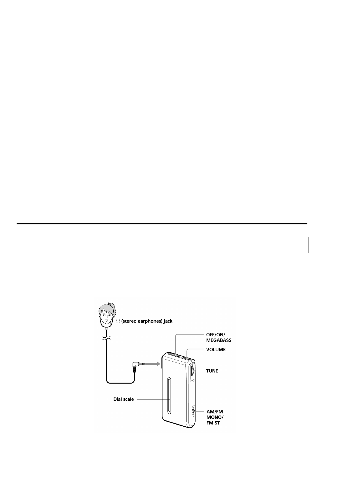
Location and Function of Controls .................................... 2
2. DISASSEMBLY
2-1. Cabinet (Rear)............................................................. 3
2-2. Main Board ................................................................. 3
3. DIAL POINTER INSTALLATION ........................... 4
4. ADJUSTMENTS .......................................................... 5
5. DIAGRAMS.................................................................... 6
6. EXPLODED VIEW.................................................. 10
7. ELECTRICAL PARTS LIST.................................... 11
Flexible Circuit Board Repairing
• Keep the temperature of the soldering iron around 270°C during
repairing.
• Do not touch the soldering iron on the same conductor of the
circuit board (within 3 times).
• Be careful not to apply force on the conductor when soldering or
unsoldering.
Notes on chip component replacement
• Never reuse a disconnected chip component.
• Notice that the minus side of a tantalum capacitor may be damaged by heat.
LOCATION AND FUNCTION OF CONTROLS
SECTION 1
GENERAL
This section is extracted from
instruction manual.
2
DISASSEMBLY
)
r
The equipment can be removed using the following procedure.
SRF-S84
SECTION 2
Set
Note : Follow the disassembly procedure in the numerical order given.
Cabinet (rear)
Main board
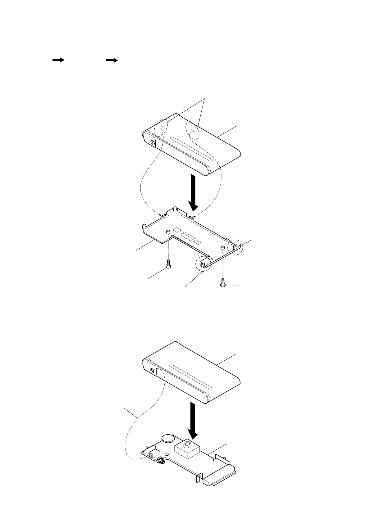
2-1. CABINET (REAR)
4
3
Claws
Cabinet (front)
2
Claw
2-2. MAIN BOARD
Cabinet (rear)
4
Screw(B1.7 x 8)
1
1
2
Claw
2
Screw(B1.7 x 8)
Cabinet (front
Main board
3
SRF-S84
)
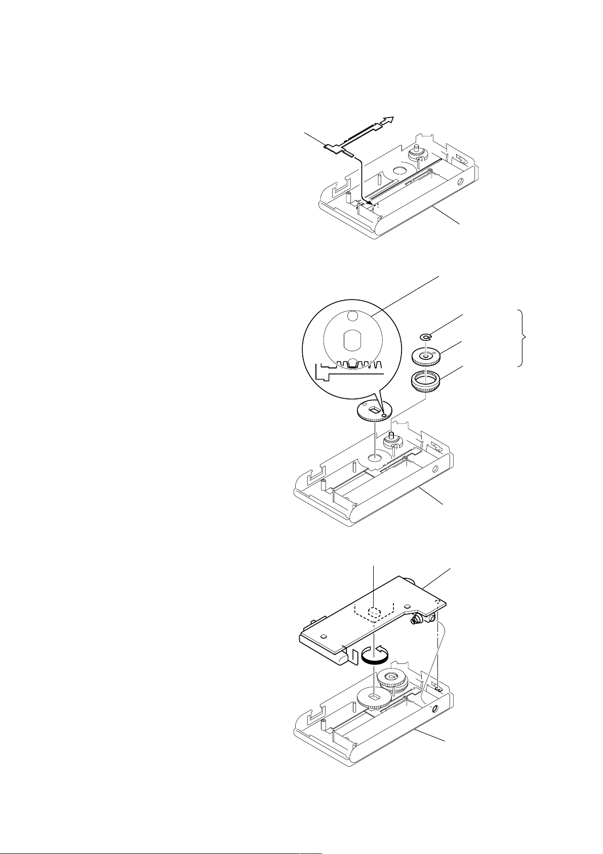
SECTION 3
DIAL POINTER INSTALLATION
Note : Follow the installation procedure in the numerical order given.
1 Insert the pointer into the cabinet (rear).
2 Slide the pointer to arrow direction.
3 Install the gear (tuning capacitor), and engage with pointer as
a figure.
4 Install the gear (midway) and the knob (tuning), and fasten it
with washer.
Pointer
1
Pointer
2
3
Cabinet (rear
Gear (tuning cpacitor)
Washer
Knob (tuning)
Gear (midway)
4
5 Turn the CV1 in a direction as a figure.
6 Install the main board.
CV1
5
Cabinet (rear)
6
Main board
Cabinet (rear)
4
SECTION 4
r
CT1 : FM Frequency Coverage Adjustment
CT4 : AM Frequency Coverage Adjustment
L3 : AM Frequency Coverage Adjustment
L6: FM Frequency Coverage Adjustment
L2: FM 2ND OSC Adjustment
L5 : AM Tracking Adjustment
CT3: AM Tracking Adjustment
L1 : FM Tracking Adjustment
L4 : FM VCO Adjustment
CT2 : FM Tracking Adjustment
MAIN BOARD (SIDE B)MAIN BOARD (SIDE A)
FM RF signal
generator
Carrier frequency : 98MHz
Modulation : no modulation
Output level : 100dB µV(100mV)
TP6 (RF IN)
MAIN board
0.01 µF
Q1
Q1
ADJUSTMENTS
SRF-S84
TUNER SECTION
AM Section
Band : AM
Volume : MAX
AM RF signal
generator
30% amplitude modulation by 400Hz
signal.
Output level : as low as possible
FM Section
Band : FM
Volume : MAX
FM RF signal
generator
22.5: kHz frequency deviation by
400Hz signal
Output level : as low as possible
0dB = 1µV
Put the lead-wire
antenna close to
the set.
16 Ω
0.06 µF
level mete
TP6 (RF IN)
MAIN board
• Repeat the procedures in each adjustment several times, and the
frequency coverage and tracking adjustments should be finally
done by the trimmer capacitors.
AM FREQUENCY COVERAGE ADJUSTMENT
Adjust for a maximum reading on level meter.
L3
CT4
AM TRACKING ADJUSTMENT
520kHz
1,650kHz
Adjust for a maximum reading on level meter.
L5
CT3
FM FREQUENCY COVERAGE ADJUSTMENT
520kHz
1,650kHz
Adjust for a maximum reading on level meter.
L6
CT1
FM TRACKING ADJUSTMENT
86.5MHz
109.5MHz
Adjust for a maximum reading on level meter.
L1
CT2
86.5MHz
109.5MHz
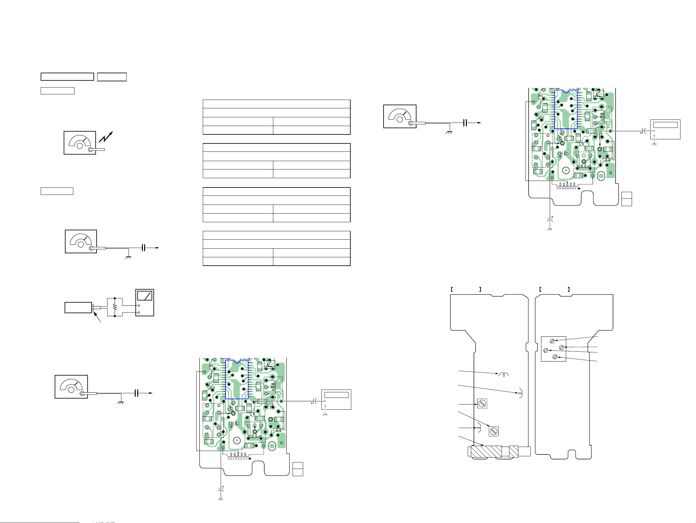
2nd OSC Adjustment
Procedure :
1. Connect the frequency counter to TP10 as shown the figure.
2. Turn the set to 98MHz.
3. Adjust L2 for 57.1MHz reading on frequency counter.
Standard Value : 56.85 –57.35MHz
Adjustment Location :
Connect Location :
[MAIN BOARD] (SIDE B)
30
1
C20
C23
C21
R4
L6
C18
S1
-2 -1
TP8
10µF
IC1
15
C22
C10
TP8
C19
L5
AM
FERRITE-ROD
ANTENNA
25
20
16
R11
L3
Frequency
C8
C12
C11
C3
C7
C9
TP10
TP9
L4
R3
TP10
C4
L2
counter
1µF
11
1-682-982-
(11)
FM VCO Adjustment
Procedure :
FM RF signal
generator
Carrier frequency : 98MHz
Modulation : no modulation
Output level : 100dB µV(100mV)
1. Connect the frequency counter to TP9 as shown the figure.
2. Turn the set to 98MHz.
3. Adjust L4 for 38kHz reading on frequency counter.
Standard Value : 37.95 –38.05kHz
set
Headphone jack (J1)
0.01 µF
+
–
TP6 (RF IN)
MAIN board
Connect Location :
[MAIN BOARD] (SIDE B)
30
1
C20
C23
L6
C18
C21
S1
-2 -1
R4
TP8
10µF
IC1
15
C22
C10
TP8
C19
L5
AM
FERRITE-ROD
ANTENNA
25
20
16
R11
L3
Frequency
C8
C12
C11
C3
C7
C9
TP10
TP9
L4
R3
TP9
C4
L2
counter
1µF
11
1-682-982-
(11)
55
 Loading...