

Sony SRFM-55 Service manual
SRF-M55
SERVICE MANUAL
Ver 1.0 1999.09
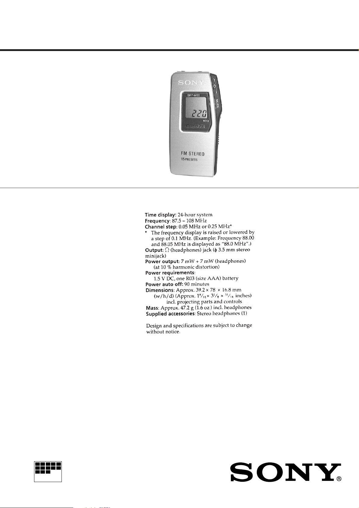
SPECIFICATIONS
AEP Model
E Model
Chinese Model
MICROFILM
FM STEREO PLL SYNTHESIZED RADIO
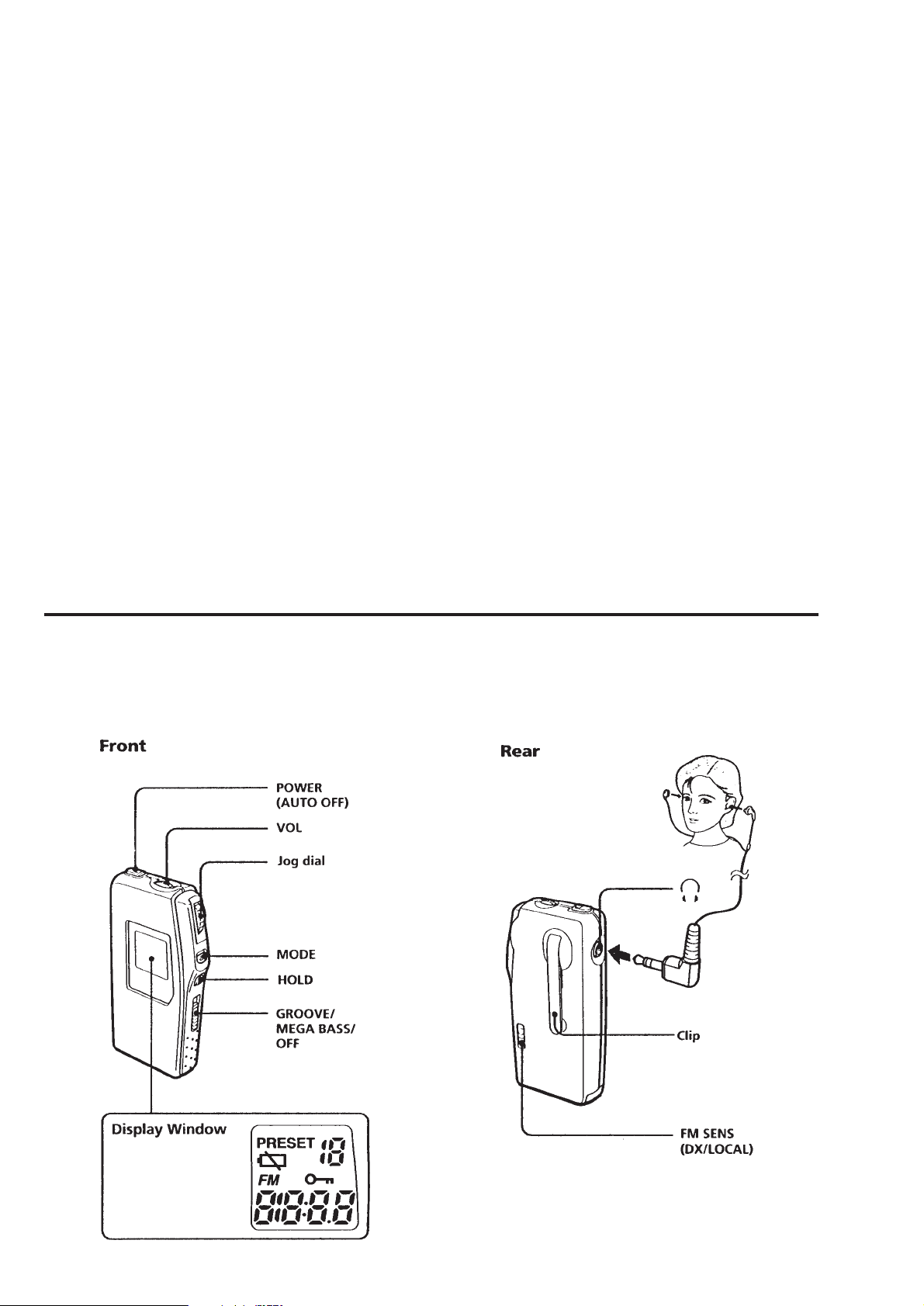
TABLE OF CONTENTS
Specifications ........................................................................... 1
1. GENERAL
Location and Function of Controls .................................... 2
Flexible Circuit Board Repairing
• Keep the temperature of the soldering iron around 270°C during
repairing.
• Do not touch the soldering iron on the same conductor of the
circuit board (within 3 times).
• Be careful not to apply force on the conductor when soldering or
unsoldering.
2. DISASSEMBLY
2-1. “Cabinet ASSY, Front”, “Cabinet ASSY, Rear” ......... 3
2-2. Main Board ................................................................. 3
2-3. LCD201 ...................................................................... 4
2-4. Microcomputer Board................................................. 4
3. ADJUSTMENTS .......................................................... 5
4. DIAGRAMS
4-1. Explanation of IC Terminals....................................... 6
4-2. Block Diagrams .......................................................... 7
4-3. Printed Wiring Boards .............................................. 10
4-4. Schematic Diagram................................................... 13
5. EXPLODED VIEW..................................................... 17
6. ELECTRICAL PARTS LIST.................................... 18
SECTION 1
GENERAL
Notes on chip component replacement
• Never reuse a disconnected chip component.
• Notice that the minus side of a tantalum capacitor may be damaged by heat.
LOCATION AND FUNCTION OF CONTROLS
– 2 –

SECTION 2
DISASSEMBLY
r
The equipment can be removed using the following procedure.
Cabinet ASSY, Front
Main board
Set
Cabinet ASSY, Rear
Microcomputer board
Note : Follow the disassembly procedure in the numerical order given.
2-1. “CABINET ASSY, FRONT”, “CABINET ASSY, REAR”
2
4
Flexible board
(10 core)
Claws
LCD201
3
Cabinet ASSY, front
2
Claws
5
LCD flexible board (13 core)
2
Claw
2-2. MAIN BOARD
Lid, battery case
1
Screws (B1.7x8)
Button (power)
4
Cabinet ASSY, rear
2
Main board
1
3
Claw
– 3 –
3
Claw
Cabinet ASSY, front

2-3. LCD201
t
LCD201
2
1
Cabinet ASSY, fron
Claws
2-4. MICROCOMPUTER BOARD
Microcomputer board
4
Claws
5
1
Screws (1.4)
4
Claw
Cover, side
3
Cabinet ASSY, rear
2
Claws
– 4 –
 Loading...