

Sony SNC-RZ25, SNC-RZ50, SNC-RZ30, SNC-RX530, SNC-RX570 Installation And Operation Instructions Manual
...
UNI-OFL7C2
Outdoor and Indoor Recessed Dome Housings
Installation and Operation Instructions for the following model:
UNIOFL7C2 Outdoor Recessed Housing, clear dome, 24Vac input, Heater/ Blower
Note: AC 24V power supply for the camera and the heater/blower is an installer/reseller provided item.
Please refer to Camera Manual for power consumption details.
Note: Please note that to achieve the increased depth with the aspheric design for optimal camera
lens to capsule orientation, the capsule is slightly angled around the highest section.
This creates a ”line’, visible to the naked eye, around the upper most section of the capsule.
This “line”serves as the geometric center line used to insure proper camera placement. It is
not typically seen by the camera. However, Sony RZ series PTZ cameras are able to tilt up
above the horizon to 25°, this wide range of tilt motion at a wide angle view may cause this line
to be captured in the image.
Mounting instructions for:
SNC-RZ25
SNC-RZ30
SNC-RZ50
SNC-RX530
SNC-RX550
SNC-RX570
SNC-RH124
SNC-RS44
SNC-RS46
Quick Reference: Camera Installation Steps
SNC-RZ25N............................Go to Steps 3-5
SNC-RZ30N............................Go to Steps 6-8
SNC-RZ50N............................Go to Steps 9-11
SNC-RX Series........................Go to Steps 12-18
SNC-RH/RS.............................Go to Steps 19-26
81-IN6525
10/14/2009
!
!
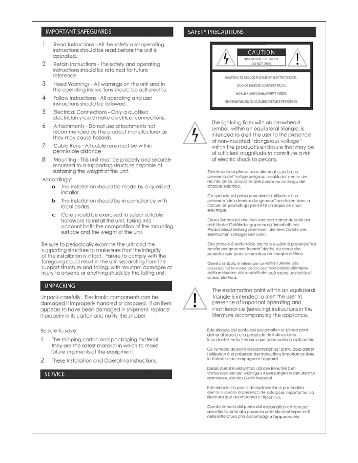
IMPORTANT SAFEGUARDS SAFETY PRECAUTIONS
1 Read Instructions - All the safety and operating
instructions should be read before the unit is
operated.
2 Retain Instructions - The safety and operating
instructions should be retained for future
reference.
CAUTION: TO REDUCE THE RISK OF ELECTRIC SHOCK,
3 Heed Warnings - All warnings on the unit and in
the operating instructions should be adhered to.
4 Follow Instructions - All operating and user
instructions should be followed.
REFER SERVICING TO QUALIFIED SERVICE PERSONNEL
5 Electrical Connections - Only a qualied
electrician should make electrical connections..
6 Attachments - Do not use attachments not
recommended by the product manufacturer as
they may cause hazards.
7 Cable Runs - All cable runs must be within
permissible distance
8 Mounting - This unit must be properly and securely
mounted to a supporting structure capable of
sustaining the weight of the unit.
Accordingly:
a. The installation should be made by a qualied
installer.
The lightning ash with an arrowhead
symbol, within an equilateral triangle, is
intended to alert the user to the presence
of non-insulated “dangerous voltage”
within the product’s enclosure that may be
of sufcient magnitude to constitute a risk
of electric shock to persons.
The exclamation point within an equilateral
triangle is intended to alert the user to
presence of important operating and
maintenance (servicing) instructions in the
literature accompanying the appliance.
CAUTION
RISK OF ELECTRIC SHOCK
DO NOT OPEN
DO NOT REMOVE COVER (OR BACK).
NO USER SERVICEABLE PARTS INSIDE.
b. The installation should be in compliance with
local codes.
c. Care should be exercised to select suitable
hardware to install the unit, taking into
account both the composition of the mounting
surface and the weight of the unit.
Be sure to periodically examine the unit and the
supporting structure to make sure that the integrity
of the installation is intact. Failure to comply with the
foregoing could result in the unit separating from the
support structure and falling, with resultant damages or
injury to anyone or anything struck by the falling unit.
UNPACKING
Unpack carefully. Electronic components can be
damaged if improperly handled or dropped. If an item
appears to have been damaged in shipment, replace
it properly in its carton and notify the shipper.
Be sure to save:
1 The shipping carton and packaging material.
They are the safest material in which to make
future shipments of the equipment.
2 These Installation and Operating Instructions.
SERVICE
If technical support or service is needed, contact Sony
at the following number:
TECHNICAL SUPPORT
8:15AM to 7:30PM (Eastern Time)
1-800-883-6817
If technical support or service is needed, contact
Sony at the following number.
TECHNICAL SUPPORT
8:15 AM to 7:30 PM
(EASTERN TIME)
1-800-883-6817
©2007 Sony Corporation
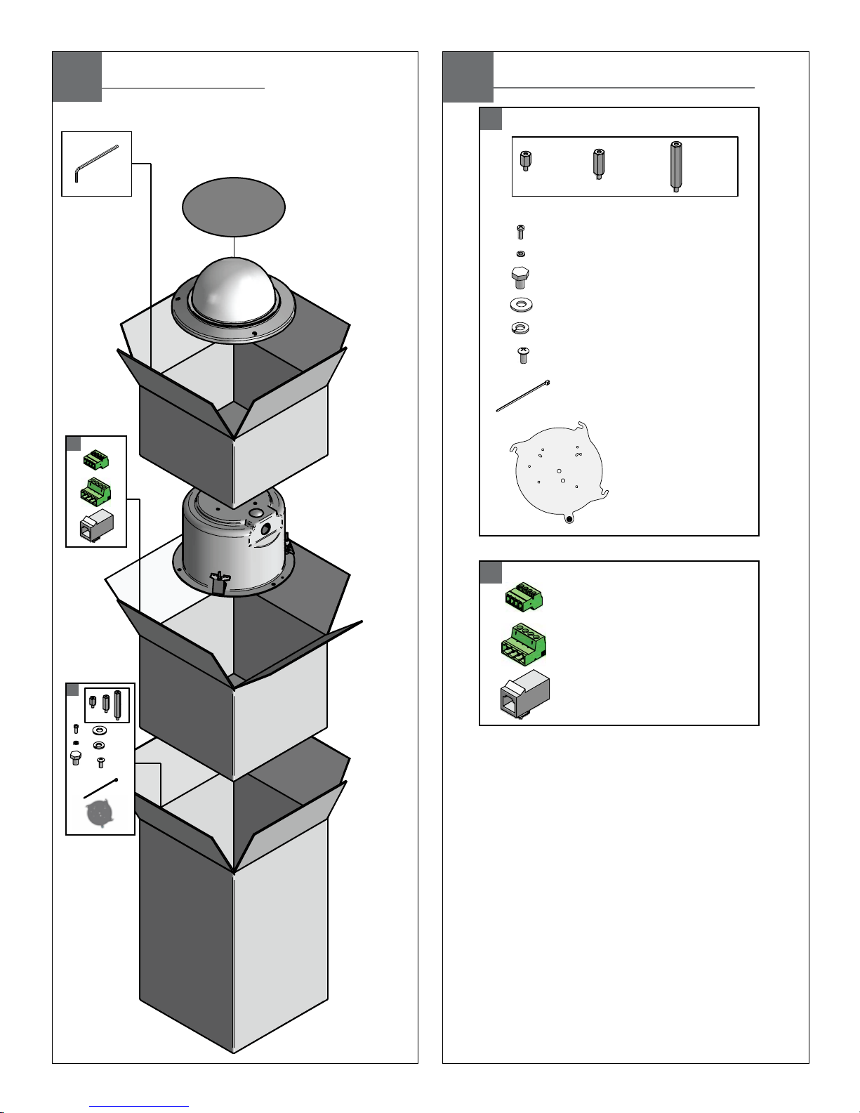
Contents of Box
A
B
Contents of Box Details
A
B
(4) M3 x 6mm Machine Screw
(1) 1/4 lock washer
(1) 1/4 x 20 Bolt
(3) 8 x 32 x 3/8" bolt
(3) Cable ties
(1) Spacer Packet
(4) M3 lock washers
(1) 1/4 flat washer
(1) Camera Bracket
(1) Spacer Packet
(1) 4 Pin Power Connector
(1) 4 Pin Auxiliary Connector
(1) RJ45 Coupling
(4)
(8)
(4)
½”
25mm
1”
50mm
2”
200mm
UNI-OFL7C2
UNI-OFL7T2
Electrical Specifications
Operating Temperature Specifications
(ONLY AL AIRE LIBRE):
UNI-ONL7C2 y UNI-ONL7T2
26 vatios en 24VAC (calentador y soplador)
Aproximadamente el 25 Watts a 24 VCA (cámara) *
* Consulte con las especificaciones de la cámara aplicable para el consumo precisa.
Herramientas Requeridas: Destornillador PrincipalPhillips
Del Destornillador Principal Plano Del 100"
(ONLY EXTÉRIEURS):
UNI-ONL7C2 et UNI-ONL7T2
26 watts à 24VAC (réchauffeur et ventilateur)
Environ 25 Watts à 24 VAC (caméra seulement) *
* Se reporter aux spécifications applicables à la consommation caméra précis.
Outils Requis: Tournevis Principal Phillips
De Tournevis Principal Plat De 100"
(IM FREIEN ONLY):
UNI-ONL7C2 u. UNI-ONL7T2
26 Watt an 24VAC (Heizung und Gebläse)
Etwa 25 W bei 24 VAC (Kamera) *
* Wenden Sie sich an geltenden Kamera Angaben zur genauen Verbrauch.
Werkzeuge Erforderten: 100"Flacher Hauptschraubenzieher-
Kreuzkopfhauptschraubenzieher
(ONLY AO AR LIVRE):
UNI-ONL7C2 & UNI-ONL7T2
26 watts em 24VAC (calefator e ventilador)
2Cerca de 25 Watts a 24 VCA (Camera Only) *
* Consulte a Ficha câmera aplicável ao consumo precisa.
As Ferramentas Requereram: Chave de fenda Principal
Phillips Da Chave de fenda Principal Lisa Do 100"
(ONLY ESTERNI):
UNI-ONL7C2 & UNI-ONL7T2
26 watt a 24VAC (riscaldatore e ventilatore)
Circa 25 Watt a 24 VAC (solo fotocamera) *
* Fare riferimento a specifiche fotocamera applicabili per il consumo precise.
Attrezzi Richiesti: Cacciavite Capo "phillips" Del Cacciavite
Capo Piano Del 100"
-20°C to +50°C (-4°F to +122°F)
(OUTDOOR ONLY):
UNI-OFL7C2 & UNI-OFL7T2
Power 24VAC, Class 2 Only
26 Watts at 24 VAC (Heater and Blower)
Approximately 25 Watts at 24 VAC (Camera)*
*Refer to applicable camera specs for price consumption
Tools Required: .100" Flat Head Screwdriver
Phillips Head Screwdriver
MM
2
AWG
,5 ,75 1,0 1,5 2,5 4 6
22 20 18 16 14 12 10
The beam angle may be adjusted on the
bottom of the unit.
• Éstos se recomiendan las distancias máximas para
24VAC con una gota del voltage del 10%.
• Ceux-ci sont recommandés des distances maximum
pour 24VAC avec une baisse de volatage de 10%.
• Diese werden maximale Abstände für 24VAC mit einem
das 10% volatage Tropfen empfohlen.
• Estes são recomendados distâncias máximas para
24VAC com uma gota do volatage de 10%.
• Questi sono suggeriti distanze massime per 24VAC con
una goccia di volatage di 10%.
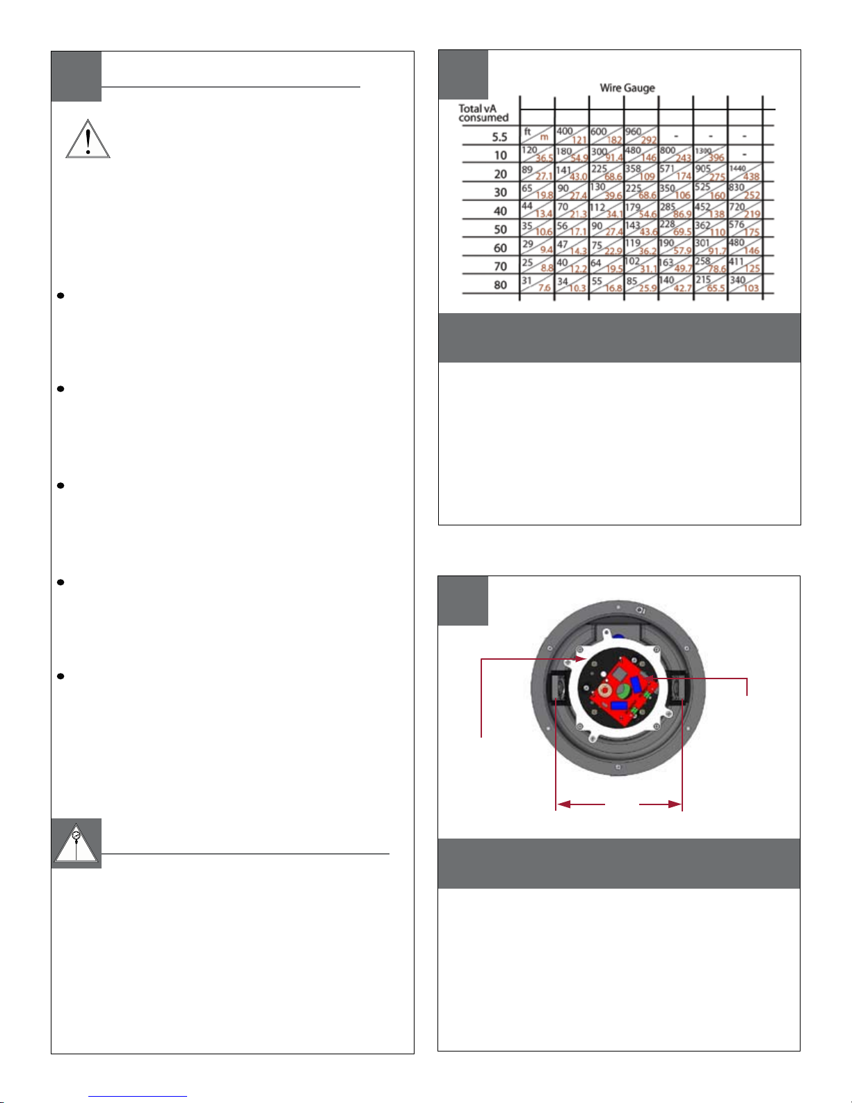
These are recommended maximum distances
for 24VAC with a 10% voltage drop.
Location of housing components
• Localización de los componentes de la cubierta
• Endroit des composants de logement
• Position der Gehäusebestandteile
• Posição de componentes da carcaça
• Posizione delle componenti dell'alloggiamento
FANS
(HEATERS BEHIND
BRACKETS)
MOUNTING
PLATE
24VAC - 12VDC
POWER SUPPLY
1
2
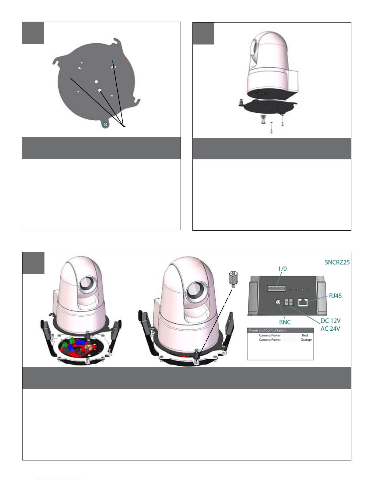
Remove the quick release plate from the
packet assembly
• Quite la placa rápida del lanzamiento de la cubierta
montaje de paquete.
• Enlevez le plat rapide de dégagement du logement
paquet.
• Entfernen Sie die schnelle Freigabeplatte vom
Gehäuse Paketierung .
• Remova a placa rápida da liberação da carcaça
conjunto de pacote.
• Rimuova la piastra rapida del rilascio assemblea di
pacchetto
SNCRZ25
MOUNTING HOLES
Mount the camera to the plate using the
appropriate pattern and hardware.
• Monte la cámara fotográfica a la placa usando el
patrón apropiado.
• Montez l'appareil-photo au plat en utilisant le modèle
approprié.
• Bringen Sie die Kamera zur Platte mit dem passenden
Muster an.
• Monte a câmera à placa usando o teste padrão
apropriado.
• Monti la macchina fotografica alla piastra usando il
modello adatto.
SNCRZ25
Align tabs in mounting plate with spacers and turn counterclockwise to secure.
• Alinee las lengüetas en placa de montaje con los espaciadores y dé vuelta a la izquierda para asegurar.
• Alignez les étiquettes dans le plat de support avec des entretoises et tournez dans le sens contraire des aiguilles
d'une montre pour fixer.
• Richten Sie Vorsprünge in der Montageplatte mit Distanzscheiben aus und drehen Sie nach links, um zu sichern.
• Alinhe abas na placa de montagem com os espaçadores e gire-as no sentido anti-horário para fixar-se.
• Allinei le linguette in giunto di supporto con i distanziatori e giri in senso antiorario per fissare.
(24VAC)
(24VAC)
Sensor Input/Output Violet
Sensor Input/Output Gray
½”
3
4
5
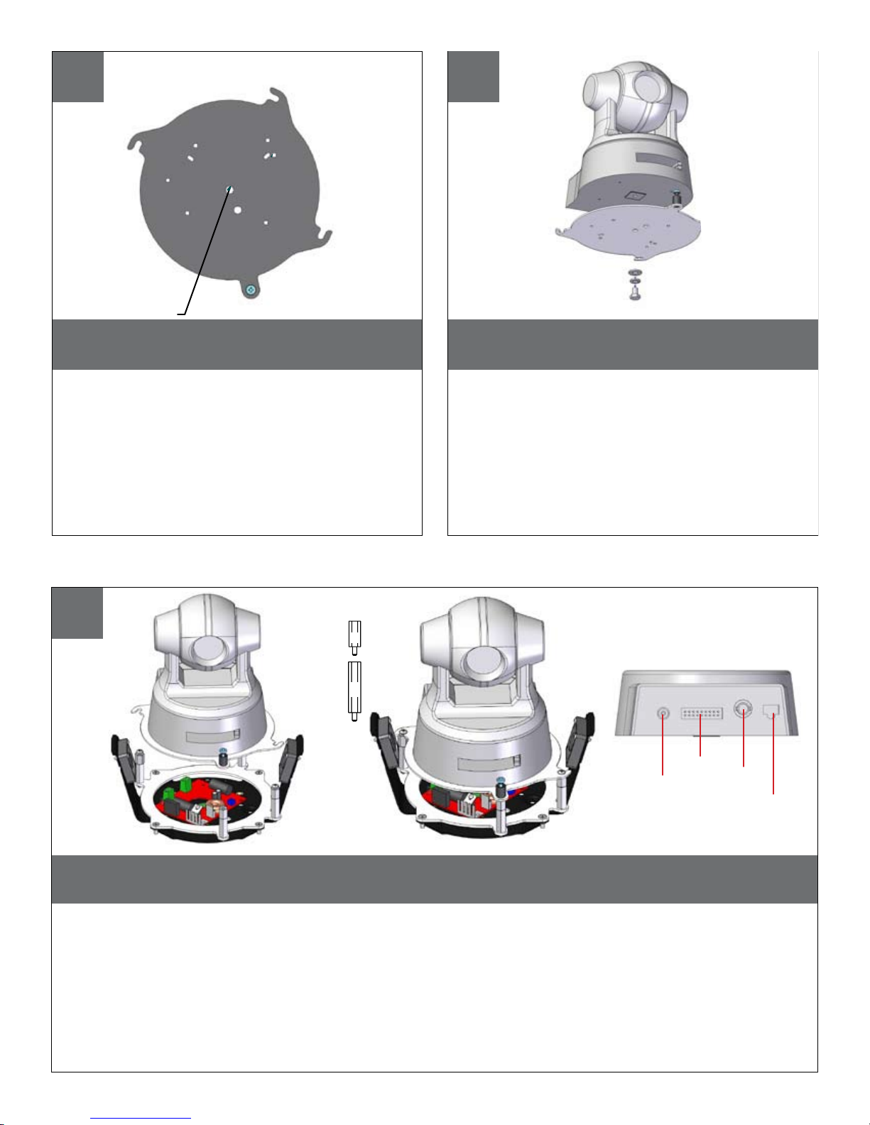
Remove the quick release plate from the
housing.
• Quite la placa rápida del lanzamiento de la cubierta.
• Enlevez le plat rapide de dégagement du logement.
• Entfernen Sie die schnelle Freigabeplatte vom
Gehäuse.
• Remova a placa rápida da liberação da carcaça.
• Rimuova la piastra rapida del rilascio
dall'alloggiamento.
SNC RZ30
MOUNTING HOLES
Mount the camera to the plate using the
appropriate pattern.
• Monte la cámara fotográfica a la placa usando el
patrón apropiado.
• Montez l'appareil-photo au plat en utilisant le
modèle approprié.
• Bringen Sie die Kamera zur Platte mit dem passenden Muster an.
• Monte a câmera à placa usando o teste padrão
apropriado.
• Monti la macchina fotografica alla piastra usando
il modello adatto.
SNCRZ30
Align tabs in mounting plate with the base plate and turn counterclockwise to secure. When
completed, go to step 27.
• Alinee las lengüetas en placa de montaje con el embase y dé vuelta a la izquierda para asegurar. Cuando se
haya completado, vaya al paso 27.
• Alignez les étiquettes dans le plat de support avec l'embase et tournez dans le sens contraire des aiguilles d'une
montre pour fixer. Une fois terminé, passez à l'étape 27.
• Richten Sie Vorsprünge in der Montageplatte mit der Grundplatte aus und drehen Sie nach links, um zu sichern.
Wenn der Vorgang abgeschlossen, gehen Sie bis 27 Schritt.
• Alinhe abas na placa de montagem com a placa baixa e gire-as no sentido anti-horário para fixar-se. Quando
estiver concluída, vá para a etapa 27.
• Allinei le linguette in giunto di supporto con la base di appoggio e giri in senso antiorario per fissare. Una volta
completato, andare al passaggio 27.
SNC-RZ30
(26mm) 1"
(13mm) ½"
12 VDC
Power
I/O
BNC
RJ45
6
SNCRZ30
7
8
 Loading...