

Sony SNC-RX530P, SNC-RX570P User Manual
3-286-973-11 (1)
Network Camera
Installation Manual
Before operating the unit, please read this manual thoroughly and
retain it for future reference.
SNC-RX570N/RX570P
SNC-RX550N/RX550P
SNC-RX530N/RX530P
2007 Sony Corporation Printed in Japan
Owner’s Record
The model and serial numbers are located on the bottom. Record these
numbers in the spaces provided below.
Refer to these numbers whenever you call upon your Sony dealer regarding
this product.
Model No. Serial No.
WARNING
To reduce a risk of re or electric shock, do not expose
this product to rain or moisture.
To avoid electrical shock, do not open the cabinet. Refer
servicing to qualied personnel only.
WARNING
This installation should be made by a qualied service person and should
conform to all local codes.
WARNING
A readily accessible disconnect device shall be incorporated in the building
installation wiring.
WARNING (for Installers only)
Instructions for installing the equipment on the ceiling:
After the installation, ensure the connection is capable of supporting ve
times the weight of the equipment downwards.
CAUTION
The rating label is located on the bottom.
CAUTION for LAN port
For safety reason, do not connect the LAN port to any network devices that
might have excessive voltage.
Power Supply
Caution for U.S.A. and Canada
The SNC-RX570N/RX550N/RX530N operates on 24V AC or 12V DC.
The SNC-RX570N/RX550N/RX530N automatically detects the power.
Use a Class 2 power supply which is UL Listed (in the U.S.A.) or CSA-certied
(in Canada).
Caution for other countries
The SNC-RX570N/RX570P/RX550N/RX550P/RX530N/RX530P operates on
24V AC or 12V DC.
The SNC-RX570N/RX570P/RX550N/RX550P/RX530N/RX530P automatically
detects the power.
Use a power supply rated 24 V AC or 12 V DC which meets the requirements
for SELV (Safety Extra Low Voltage) and complies with Limited Power Source
according to IEC 60950.
For customers in the U.S.A. (SNC-RX570N/RX550N/RX530N only)
This device complies with Part 15 of the FCC Rules. Operation is subject
to the following two conditions: (1) This device may not cause harmful
interference, and (2) this device must accept any interference received,
including interference that may cause undesired operation.
NOTE: This equipment has been tested and found to comply with the limits
for a Class A digital device, pursuant to part 15 of the FCC Rules. These limits
are designed to provide reasonable protection against harmful interference
when the equipment is operated in a commercial environment. This
equipment generates, uses, and can radiate radio frequency energy and, if
not installed and used in accordance with the instruction manual, may cause
harmful interference to radio communications. Operation of this equipment
in a residential area is likely to cause harmful interference in which case the
user will be required to correct the interference at his own expense.
You are cautioned that any changes or modications not expressly approved
in this manual could void your authority to operate this equipment.
All interface cables used to connect peripherals must be shielded in order to
comply with the limits for a digital device pursuant to Subpart B or Part 15 of
FCC Rules.
For customers in Canada (SNC-RX570N/RX550N/RX530N only)
This Class A digital apparatus complies with Canadian ICES-003.
Cet appareil numérique de la classe A est conforme à la norme NMB-003 du
Canada.
For the customers in Europe
The manufacturer of this product is Sony Corporation, 1-7-1 Konan, Minatoku, Tokyo, Japan.
The Authorized Representative for EMC and product safety is Sony
Deutschland GmbH, Hedelnger Strasse 61, 70327 Stuttgart, Germany.
For any service or guarantee matters please refer to the addresses given in
separate service or guarantee documents.
For the customers in Europe, Australia and New Zealand
WARNING
This is a Class A product. In a domestic environment, this product may cause
radio interference in which case the user may be required to take adequate
measures.
In the case that interference should occur, consult your nearest authorized
Sony service facility.
This apparatus shall not be used in the residential area.
ATTENTION
The electromagnetic elds at specic frequencies may inuence the picture
of the unit.
For the customers in Taiwan only
Features
Monitoring of a high-quality live image from the camera is possible. The
maximum frame rate is 30 fps for SNC-RX570N/RX550N/RX530N and 25 fps for
SNC-RX570P/RX550P/RX530P.
Three video compression modes (video codecs) JPEG/MPEG4/H.264 are
supported.
Single codec mode and Dual codec mode are switchable.
A high-speed (300° rotation/second) pan/tilt mechanism is equipped. This
allows 360° endless panning and -90° to 0° tilting.
Optical zoom of 36 magnications (SNC-RX570N/P), 26 magnications (SNC-
RX550N/P) or 18 magnications (SNC-RX530N/P), and digital zoom of 12
magnications are provided.
Inserting the optional wireless card enables wireless transmission of camera
images.
Up to 16 preset positions and 5 tour programs can be saved.
Intelligent object detection function is provided.
Up to 20 users can view an image from the camera at the same time.
Date/time can be superimposed on the image.
Notes on Use
Data and security
You should keep in mind that the images or audio you are monitoring may be
protected by privacy and other legal rights, and the responsibility for making
sure you are complying with applicable laws is yours alone.
Access to the images and audio is protected only by a user name and the
password you set up. No further authentication is provided nor should you
presume that any other protective ltering is done by the service. Since
the service is Internet-based, there is a risk that the image or audio you are
monitoring can be viewed or used by a third-party via the network.
SONY IS NOT RESPONSIBLE, AND ASSUMES ABSOLUTELY NO LIABILITY TO YOU
OR ANYONE ELSE, FOR SERVICE INTERRUPTIONS OR DISCONTINUATIONS OR
EVEN SERVICE CANCELLATION. THE SERVICE IS PROVIDED AS-IS, AND SONY
DISCLAIMS AND EXCLUDES ALL WARRANTIES, EXPRESS OR IMPLIED, WITH
RESPECT TO THE SERVICE INCLUDING, BUT NOT LIMITED TO, ANY OR ALL
IMPLIED WARRANTIES OF MERCHANTABILITY, FITNESS FOR A PARTICULAR
PURPOSE, OR THAT IT WILL OPERATE ERROR-FREE OR CONTINUOUSLY.
Security conguration is essential for wireless LAN. Should a problem
occur without setting security, or due to the limitation of the wireless LAN
specications, SONY shall not be liable for any damage.
Always make a test recording, and verify that it was recorded successfully.
SONY WILL NOT BE LIABLE FOR DAMAGES OF ANY KIND INCLUDING, BUT NOT
LIMITED TO, COMPENSATION OR REIMBURSEMENT ON ACCOUNT OF FAILURE
OF THIS UNIT OR ITS RECORDING MEDIA, EXTERNAL STORAGE SYSTEMS OR
ANY OTHER MEDIA OR STORAGE SYSTEMS TO RECORD CONTENT OF ANY TYPE.
Always verify that the unit is operating properly before use. SONY WILL NOT
BE LIABLE FOR DAMAGES OF ANY KIND INCLUDING, BUT NOT LIMITED TO,
COMPENSATION OR REIMBURSEMENT ON ACCOUNT OF THE LOSS OF PRESENT
OR PROSPECTIVE PROFITS DUE TO FAILURE OF THIS UNIT, EITHER DURING THE
WARRANTY PERIOD OR AFTER EXPIRATION OF THE WARRANTY, OR FOR ANY
OTHER REASON WHATSOEVER.
If you lose data by using this unit, SONY accepts no responsibility for
restoration of the data.
Operating or storage location
Do not shoot an extremely bright object (an illumination, the sun, etc.). Also,
avoid operating or storing the camera in the following locations, as these can be
a cause of a malfunction.
Extremely hot or cold places (Operating temperature: 0 °C to +50 °C [32 °F to
122 °F])
Exposed to direct sunlight for a long time, or close to heating equipment (e.g.,
near heaters)
Close to sources of strong magnetism
Close to sources of powerful electromagnetic radiation, such as radios or TV
transmitters
Locations subject to strong vibration or shock
Ventilation
To prevent heat buildup, do not block air circulation around the camera.
Transportation
When transporting the camera, repack it as originally packed at the factory or in
materials of equal quality.
Cleaning
Use a blower to remove dust from the lens.
Use a soft, dry cloth to clean the external surfaces of the camera. Stubborn
stains can be removed using a soft cloth dampened with a small quantity of
detergent solution, then wipe dry.
Do not use volatile solvents such as alcohol, benzene or thinners as they may
damage the surface nishes.
Note on laser beams
Laser beams may damage a CCD. You are cautioned that the surface of a CCD
should not be exposed to laser beam radiation in an environment where a laser
beam device is used.
Phenomena Specic to CCD Image Sensors
The following phenomena that may appear in images are specic to CCD (Charge
Coupled Device) image sensors. They do not indicate malfunctions.
White ecks
Although the CCD image sensors are produced with high-precision technologies,
ne white ecks may be generated on the screen in rare cases, caused by cosmic
rays, etc.
This is related to the principle of CCD image sensors and is not a malfunction.
The white ecks especially tend to be seen in the following cases:
- when operating at a high environmental temperature
- when you have raised the gain (sensitivity)
- when using the slow shutter
Vertical smear
When an extremely bright object, such as a strong spotlight or ashlight, is
being shot, vertical tails may be produced on the screen, or the image may be
distorted.
Aliasing
When ne patterns, stripes, or lines are shot, they may appear jagged or icker.
About a “Memory Stick”
Available types of “Memory Stick” for the unit
You can use “Memory Stick,” “MagicGate Memory Stick” and “Memory Stick
PRO” with the unit. However, because the unit does not support the MagicGate
standards, data recorded with the unit is not subject to MagicGate copyright
protection.
Note
The data recorded with this unit is not compatible with the other units, even if
they support “Memory Stick.”
Before using a “Memory Stick”
Terminal
Write-protect tab
Labeling position
When you set the “Memory Stick” write-protect tab to “LOCK,” data cannot be
recorded, edited, or erased.
Data may be damaged if:
You remove the “Memory Stick” or turn o the unit while it is reading or
writing data.
You use the “Memory Stick” in a location subject to the eects of static
electricity or electric noise.
Notes
Do not attach any other material than the supplied label onto the label space.
Attach the label so that it does not stick out beyond the labeling position.
Carry and store the “Memory Stick” in its case.
Prevent metallic objects or your nger from coming into contact with the
metal parts of the connecting section.
Do not strike, bend, or drop the “Memory Stick.”
Do not disassemble or modify the “Memory Stick.”
Do not allow the “Memory Stick” to get wet.
Do not use or store the “Memory Stick” in a location that is:
extremely hot, such as in a car parked in the sun.
under direct sunlight.
very humid or subject to corrosive substances.
About the Supplied Manuals
Installation Manual (this document)
This Installation Manual describes the names and functions of parts and controls
of the Network Camera, gives connection examples and explains how to set up
the camera. Be sure to read the Installation Manual before operating.
User’s Guide (stored in the CD-ROM)
The User’s Guide describes how to set up the camera and how to control the
camera via a Web browser.
After installing and connecting the camera correctly, operate referring to this
User’s Guide.
Using the CD-ROM Manuals
The supplied CD-ROM disc includes the User’s Guides for this unit (Japanese,
English, French, German, Spanish, Italian and Chinese versions) in PDF format.
Preparations
The Adobe Reader Version 6.0 or higher must be installed on your computer in
order to use the User’s Guide stored in the CD-ROM disc.
Note
If Adobe Reader is not installed, it may be downloaded from the following URL:
http://www.adobe.com/
Reading the manual in the CD-ROM
1 Insert the CD-ROM in your CD-ROM drive.
A cover page appears automatically in your Web browser.
If it does not appear automatically in the Web browser, double-click on the
index.htm le on the CD-ROM.
2 Select and click on the manual that you want to read.
This opens the PDF le of the manual.
Clicking an item in the Table of Contents allows you jump to the relevant
page.
Notes
The les may not be displayed properly, depending on the version of Adobe
Reader. In this case, install the latest version, which you can download from
the URL mentioned in “Preparations” above.
If you have lost or damaged the CD-ROM, you can purchase replacement.
Contact your Sony service representative.
Adobe and Acrobat Reader are trademarks of Adobe Systems Incorporated in the
United States and/or other countries.
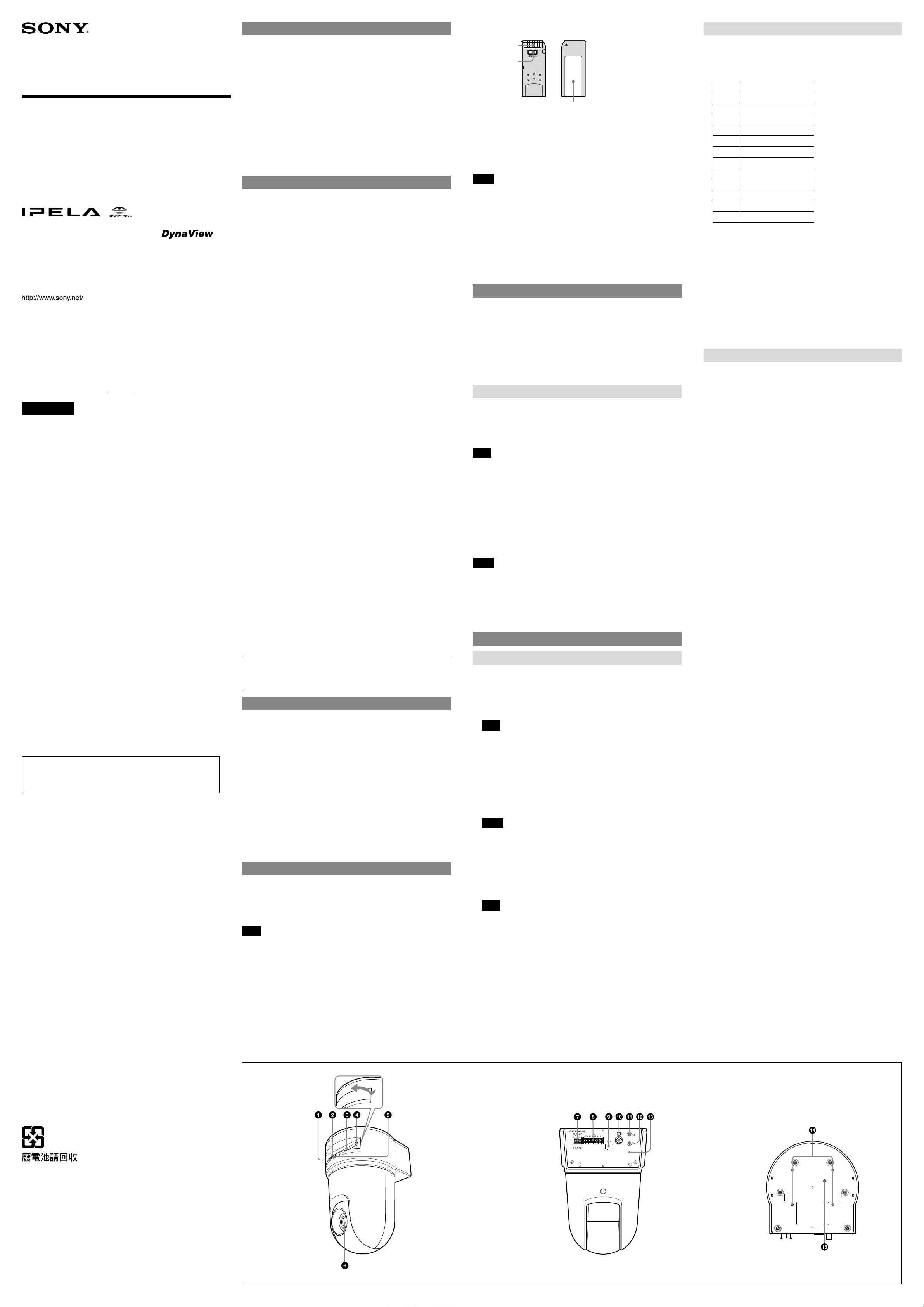
Location and Function of Part
Front
NETWORK indicator (green)
The indicator lights up or ashes in green when the camera is connected to
the network.
The indicator goes o when the camera is not connected to the network.
Memory Stick slot
Insert a “Memory Stick” (not supplied) into the slot.
Note
Insert the “Memory Stick” with its front side towards the bottom of the
camera.
PC card slot
This slot is used for the optional SNCA-CFW1/SNCA-CFW5* wireless card or
recommended ATA memory card.
In case of the wireless card: Insert the SNCA-CFW1 or SNCA-CFW5* into a
commercially available type II-PCMCIA adaptor and insert the adaptor into
the PC card slot.
In case of the recommended ATA memory card: Insert the “Memory Stick”
into the optional PC card adapter and insert the adapter into the PC card slot.
Notes
Insert the PC card with its front side towards the bottom of the camera.
For the veried ATA memory cards, contact your authorized Sony dealer.
PC card lever
Press the lever to remove the PC card from the PC card slot.
POWER indicator (green)
When the power is supplied to the camera, the camera starts checking the
system. If the system works normally, this indicator lights up.
Lens
Note
The four edges of an image may be dark depending on the zoom position.
This is a phenomenon related to the structure of the camera, and does not
cause a problem.
* SNCA-CFW5 is not available in some countries and areas. For details, contact your
authorized Sony dealer.
What is MagicGate ?
MagicGate is copyright protection technology that uses encryption technology.
Rear
DC IN 12 V/AC IN 24 V (power input) terminal
Connect to a 12V DC or 24V AC power supply system.
I/O (Input/Output) port
This port is provided with an RS-232C port, two sensor inputs and two
alarm outputs.
Pin No. Pin name
1 Sensor In 1 +
2 Sensor In 1 – (GND)
3 Sensor In 2 +
4 Sensor In 2 – (GND)
5 Alarm Out 1 +
6 Alarm Out 1 –
7 Alarm Out 2 +
8 Alarm Out 2 –
9 GND
10 GND
11 RS232C . RX
12 RS232C . TX
LAN (network) port (RJ45)
Connect to the 10BASE-T or 100BASE-TX network using a network cable
(UTP, category 5).
(video output) connector (BNC type)
Outputs a composite video signal.
(line output) jack (minijack, monaural)
Connect a commercially available speaker system with the built-in
amplier.
(microphone input) jack (minijack, monaural)
Connect a commercially available microphone. This jack supports plug-
in-power microphones (rated voltage: 2.5 V DC).
Reset switch
To reset the camera to the factory default settings, supply the power to
the camera, while holding down this switch with a pointed object.
Bottom
Ceiling bracket mounting screw holes
When installing the camera on the ceiling, x the supplied ceiling
brackets to these holes.
Screw hole for fall-prevention wire rope
When installing the camera on the ceiling, x the supplied fall-prevention
wire rope to this hole using the supplied screw M4×8.
(continued on the reverse side)
1, 2
Ceiling
Fall-prevention
wire rope
Camera (rear)
Installation
Notes
Do not grasp the camera head when carrying the camera.
Do not turn the camera head manually. Doing so will result in the camera
malfunctioning.
Wiring diagram for alarm output
Camera inside
5 or 7 pin
(Alarm Output +)
Outside
5 V
Front of the
camera
3
Set the triangular
hole at the front
of the camera.
4
Upper ceiling
bracket
5
M3×8
(supplied)
6, 7
8
Ceiling
Fall-prevention wire rope
M4×8
(supplied)
Ceiling
Ceiling
Upper ceiling
bracket
M3×8
(supplied)
Lower ceiling
bracket
Ceiling
Lower ceiling
bracket
M3×8
(supplied)
Cable cover
mounting bracket
M3×8
(supplied)
Hole for
connecting cables
Ceiling
to 12 V DC
or 24 V AC
Slotted
screwdriver
Wire
1
2
Front
160 (6 3/8)
Side (with ceiling brackets)
80 (3 1/4) 80 (3 1/4) 80 (3 1/4) 191 (7 5/8)10 (13/32)
Screw hole for
wire rope
Upper ceiling bracket
45°
45°
ø88.9 (3 1/2)
Hole width
4.4 (3/16) (×4)
Hub
Network
)
8
/
1
230 (9
Side (with cable cover)
Bottom
(Adjustable range:±20°)
70 (2 7/8)
40°
83.5 (3 3/8)
LAN
Network cable
(straight, not supplied)
10BASE-T/
100BASE-TX
Lithium
battery
Front (with ceilling brackets)
160 (6 3/8)
)
8
/
3
60 (2
Hole 4 – M3 (×4)
ø107.3 (4 1/4)
Hole width
4.4 (3/16) (×4)
Unit: mm (inches)
)
8
/
5
242 (9
Hole 4 –
ø4.4 (3/16)
ø83.5 (3 3/8)
Hole width
4.4 (3/16) (×2)
)
16
/
15
46 (1
ø121.2 (4 7/8)
Hole width
4.4 (3/16) (×4)
)
8
/
3
83 (3
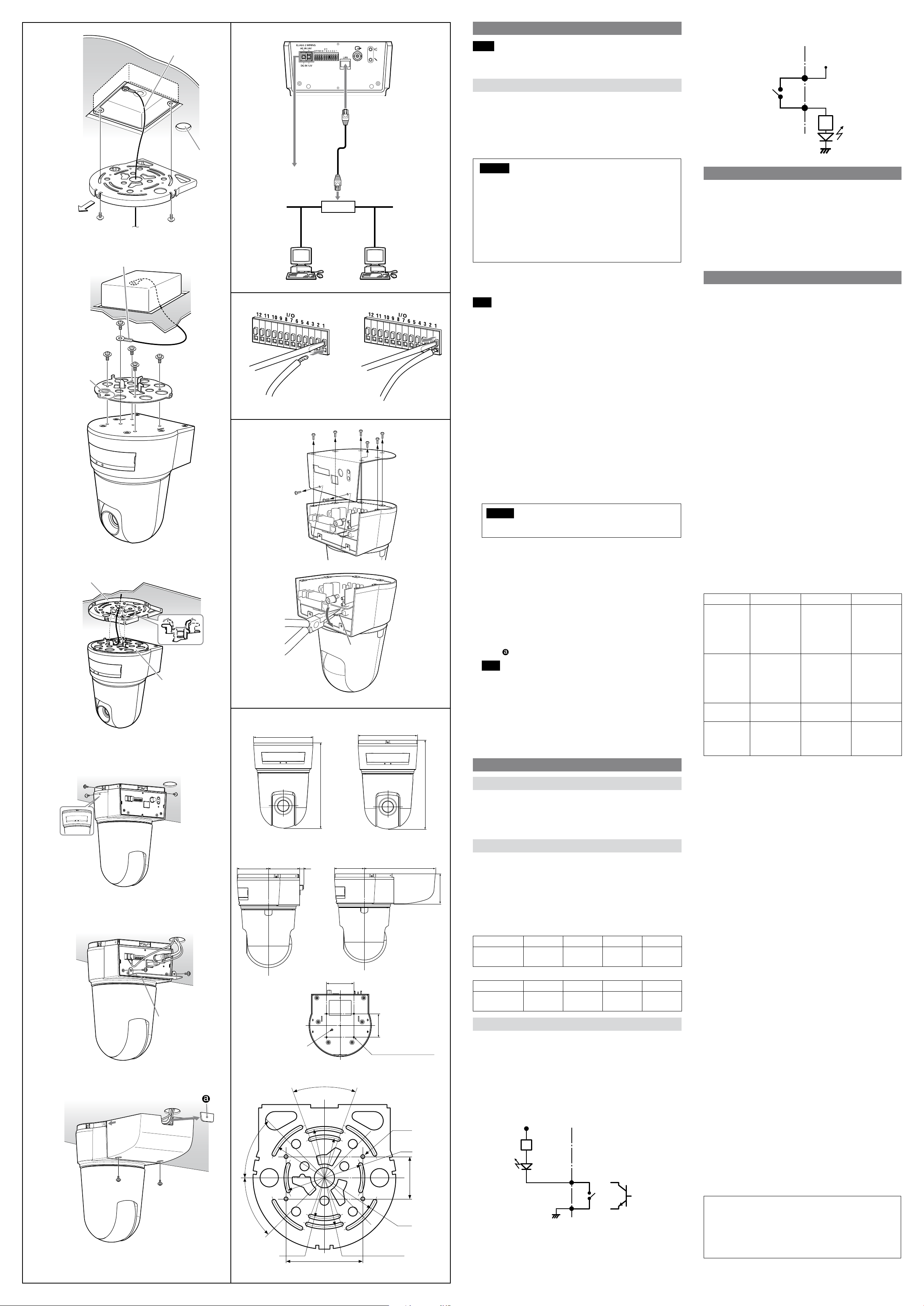
Installing the Camera on the Ceiling
You can view the image of this camera in the normal direction when the camera
is installed on the ceiling.
Using the supplied ceiling brackets, wire rope and screws, you can utilize existing
junction boxes, etc., to attach the camera to the ceiling.
When you install the camera, always install it on a level ceiling. If you have to
install it on a sloping or uneven ceiling, make sure that the place where you
install it is within ±5 degrees of the horizontal in order to ensure the pan/tilt
mechanism functions properly.
Warning
If you attach the camera in the height such as the wall or the ceiling, etc.,
entrust the installation to an experienced contractor or installer.
If you install the camera on the ceiling, ensure that the ceiling is strong
enough to withstand the weight of the camera plus the ceiling brackets
and then install the camera securely. If the ceiling is not strong enough,
the camera may fall and cause serious injury.
To prevent the camera from falling, make sure to attach the supplied
wire rope.
If you attach the camera to the ceiling, check periodically, at least once
a year, to ensure that the connection has not loosened. If conditions
warrant, make this periodic check more frequently.
Before installation
After deciding the direction in which the camera will shoot, make the required
holes for the junction box, and connecting cables.
Note
The connecting cables cannot be passed through the upper ceiling bracket. A
hole for the wiring is required in the ceiling at the back of the camera where it is
attached to the ceiling.
Installation
1 Attach the fall-prevention wire rope to the junction box in the ceiling.
Use a screw hole and a screw (not supplied) in the junction box to attach the
wire rope.
2 Attach the upper ceiling bracket to the junction box on the ceiling.
Align the holes in the bracket with those in the junction box, and use
appropriate screws (not supplied).
There is a screw hole in the rounded edge of the upper ceiling bracket. Later,
the front of the camera will be aligned with this screw hole. Attach the upper
ceiling bracket paying attention to the direction of the front of the camera.
3 Attach the lower ceiling bracket to the bottom of the camera using the
supplied four screws (M3 × 8).
Attach also the wire rope to the bottom of the camera using the supplied
screw (M4×8).
When attaching, align the screw holes on the bottom of the camera with
those in the ceiling bracket, and set the triangular hole in the ceiling bracket
at the front of the camera.
Tighten the screws a little bit at a time in the numbered order shown in the
illustration. After all of the screws are temporarily tightened in the proper
manner, securely tighten each one in turn.
Caution
To attach the ceiling bracket, use only the screws supplied with the
camera. Using other screws may damage the camera.
4 Insert the raised protrusions on the lower ceiling bracket into the spaces
provided in the upper ceiling bracket, and temporarily x them by turning
the camera with lower ceiling bracket clockwise.
5 While pushing up on the front part of the camera, attach it using the supplied
three screws (M 3 × 8), starting with the screw at position .
6 Connect the cables to the connectors on the rear of the camera.
7 To use the supplied cable cover, attach the supplied cable cover mounting
bracket to the rear of the camera using the supplied two screws (M 3 × 8).
Attach the bracket with the at surface downwards.
8 Temporarily attach the cable cover by inserting the raised protrusions on the
cable cover into the gaps at the rear of the upper ceiling cover. Then x the
cable cover using the supplied two screws (M3 × 8).
To extend the cables through the rear of the cable cover, cut out the thinner
portion of the cover using a cutter knife.
Note
Take proper steps to ensure that the load of the connected cables does not
cause problems.
Removing the camera
1 Remove two screws used to attach the cable cover in step 8 of “Installation”
and remove the cable cover.
2 Disconnect the cables from the connectors at the rear of the camera.
3 Remove three screws used to attach the camera in step 5 of “Installation.”
4 Pushing the entire camera up towards the ceiling, turn the camera
counterclockwise as far as it goes, then pull it out.
Connection
Connecting to the Network
Connect the LAN port of the camera unit to a router or hub in the network using
the network cable (straight, not supplied).
To connect to a computer
Connect the LAN port of the camera unit to the network connector of a
computer using the network cable (cross, not supplied).
Connecting the Power Source
Connect the 12 V DC or 24 V AC power supply system to the power input
terminal on the rear of the camera.
Use the 12 V DC or 24 V AC power source isolated from the 100 to 240 V AC.
The usable voltage range is as follows:
12 V DC: 10.8 to 13.2 V
24 V AC: 21.6 to 26.4 V
Use the UL cable (VW-1 style 1007) for 12 V DC or 24 V AC connection.
Recommended power cable
12 V DC
Cable(AWG)
Maximumcable
length(m (feet))
24 V AC
Cable(AWG)
Maximumcable
length(m (feet))
Connecting the I/O Cable
Using the I/O receptacle
While holding down the button on the slot to which you want to connect the
wire (AWG No. 28 to 22) with a small slotted screwdriver, insert the wire into the
slot. Then release the screwdriver from the button.
Repeat this procedure to connect all required wires.
Wiring diagram for sensor input
Mechanical switch/open collector output device
#24(0.22 mm) #22(0.33 mm) #20(0.52 mm) #18(0.83 mm)
4.5 (14.8) 7.5 (24.6) 12 (39) 21 (69)
#24(0.22 mm) #22(0.33 mm) #20(0.52 mm) #18(0.83 mm)
10.5 (34) 16.5 (54) 27.5 (90) 45.5 (149)
Camera inside
5 V
2.35 kohms
Mechanical
switch
1 or 3 pin
(Sensor In +)
2 or 4 pin (GND)
GND
Outside
or
Open collector
output device
Magnet relay
24 V AC/24 V DC, 1 A
or less
6 or 8 pin
(Alarm Output –)
Circuit example
R
GND
When You Discard the Camera
For environmental reasons, take out the lithium battery from the camera and
discard it appropriately.
1 Remove the eight screws and detach the bottom panel.
2 Hold the board on which the lithium battery is attached using long-nose
pliers. Then, bend it in the direction of the arrow illustrated to detach the
battery.
WARNING (for service personnel only)
There is danger of explosion if batteries are mishandled.
Dispose of batteries properly in accordance with the manufacturer’s
instructions and all applicable local regulations.
Specications
Network
Protocol TCP/IP, ARP, ICMP, HTTP, FTP (server/client), SMTP
Compression
Video compression format JPEG/MPEG4/H.264
Audio compression format G.711/G.726 (40,32,24,16 kbps)
Image size 640 × 480 (VGA), 384 × 288, 320 × 240 (QVGA),
Maximum frame rate SNC-RX570N/RX550N/RX530N: 30 fps
SNC-RX570P/RX550P/RX530P: 25 fps
Web browser Internet Explorer Ver. 6.0 or later
Available OS Microsoft Windows 2000, Windows XP, Windows
Computer environments CPU: Pentium 4, 1.5 GHz or higher (Pentium 4,
RAM: 256 MB or more
Display size: 1024 × 768 or more
Maximum user access 20 users
Network security Password (basic authentication),
Homepage customization Starting from a homepage in the built-in ash
Other functions Detection, image trimming, built-in clock, etc.
Camera
Signal system SNC-RX570N/RX550N/RX530N: NTSC color
SNC-RX570P/RX550P/RX530P: PAL color system
Image device 1/4 type color CCD
Total picture elements:
Eective picture elements:
SNC-RX570N/P SNC-RX550N/P SNC-RX530N/P
Lens
Minimum
object distance
Minimum
illumination
Horizontal
resolution
Shutter speed 1 to 1/10,000 s
Video S/N 50 dB or more
36x (Optical), 12x
(Digital)
f=3.4 to 122.4
mm, F1.6 to 4.5
Horizontal angle:
1.7° to 57.8°
TELE end:
1,500 mm (59
1/8 inches)
WIDE end:
320 mm
(12 5/8 inches)
1.4 lx (F1.6/50 IRE) 1 lx (F1.6/50 IRE) 0.7 lx (F1.4/50 IRE)
NTSC: 530 TV
(WIDE end)
PAL: 530 TV (WIDE
end)
Mechanism
Pan 360º, endless rotation
Tilt –90° to 0°
Interface
Network port 10BASE-T/100BASE-TX, auto negotiation (RJ-45)
I/O port Sensor input : × 2, make contact
Alarm output : × 2, 24 V AC/DC, 1 A
(mechanical relay outputs electrically
Serial interface: ×1 (RS-232C)
Video output VIDEO OUT: BNC, 1.0 Vp-p,
PC card slot PCMCIA Type II
Memory Stick slot “Memory Stick”
Microphone input Minijack (monaural)
Plug-in-power supported (rated voltage: 2.5 V
Recommended load impedance 2.2 khoms
Line output Minijack (monaural), Maximum output level: 1
Others
Power supply 12 V DC ± 10%
24 V AC ± 10%, 50/60 Hz
Power consumption 25 W max.
Operating temperature 0 °C to +50 °C (32 °F to 122 °F)
Storage temperature –20 °C to +60 °C (–4 °F to +140 °F)
Operating humidity 20 to 80 %
Storage humidity 20 to 95 %
Dimensions 230 × 160 × 160 mm (9 1/8 × 6 3/8 × 6 3/8
not including the projecting parts
Mass Approx. 2.3 kg (4 lb 14 oz)
Supplied accessories CD-ROM (User’s Guide and supplied programs)
Upper ceiling bracket (1)
Lower ceiling bracket (1)
Cable cover (1)
Cable cover mounting bracket (1)
Screws
Screw
Fall-prevention wire rope (1)
Installation Manual (this document) (1)
B&P Warranty Booklet (1) (SNC-RX570N/RX550N/
Optional accessories
Wireless card SNCA-CFW1, SNCA-CFW5*
Wireless LAN antenna SNCA-AN1
“Memory Stick” MSX-1GS (1GB), MSX-512S (512MB), MSH-128
* SNCA-CFW5 is not available in some countries and areas. For details, contact
your authorized Sony dealer.
Design and specications are subject to change without notice.
Regular parts replacement
Some of the parts that make up this product (electrolytic condenser, for
example) need replacing regularly depending on their life expectancies.
The lives of parts dier according to the environment or condition
in which this product is used and the length of time it is used, so we
recommend regular checks.
Consult the dealer from whom you bought it for details.
(client), DHCP (client), DNS (client), NTP
(client), SNMP (MIB-2), RTP/RTCP
160 × 120 (QQVGA)
Vista
2.4 GHz or higher recommended)
IP ltering
memory, an ATA memory card or a “Memory
Stick” possible
system
SNC-RX570N/RX550N/RX530N:
Approx. 410,000
SNC-RX570P/RX550P/RX530P:
Approx. 470,000
SNC-RX570N/RX550N/RX530N:
Approx. 380,000
SNC-RX570P/RX550P/RX530P:
Approx. 440,000
26x (Optical), 12x
(Digital)
f=3.5 to 91 mm,
F1.6 to 3.8
Horizontal angle:
2.2° to 54.2°
TELE end:
1,500 mm (59
1/8 inches)
WIDE end:
320 mm
(12 5/8 inches)
NTSC: 470 TV
(WIDE end)
PAL: 460 TV (WIDE
end)
Maximum speed: 300° / s
Maximum speed: 300° / s
isolated from the camera)
75 ohms, unbalanced, sync negative
DC)
Vrms
inches) (h/w/d)
(1)
M3 × 8 (11)
M4 × 8 (1)
RX530N only)
(128MB)
18x (Optical), 12x
(Digital)
f=4.1 to 73.8 mm,
F1.4 to 3.0
Horizontal angle:
2.8° to 48°
TELE end: 800 mm
(31 1/2 inches)
WIDE end:
290 mm
(11 1/2 inches)
NTSC: 470 TV
(WIDE end)
PAL: 460 TV (WIDE
end)
 Loading...