

Sony SLV-SF900, SLV-SF950, RMT-V259N, RMT-V259P, RMT-V259Q Service Manual
...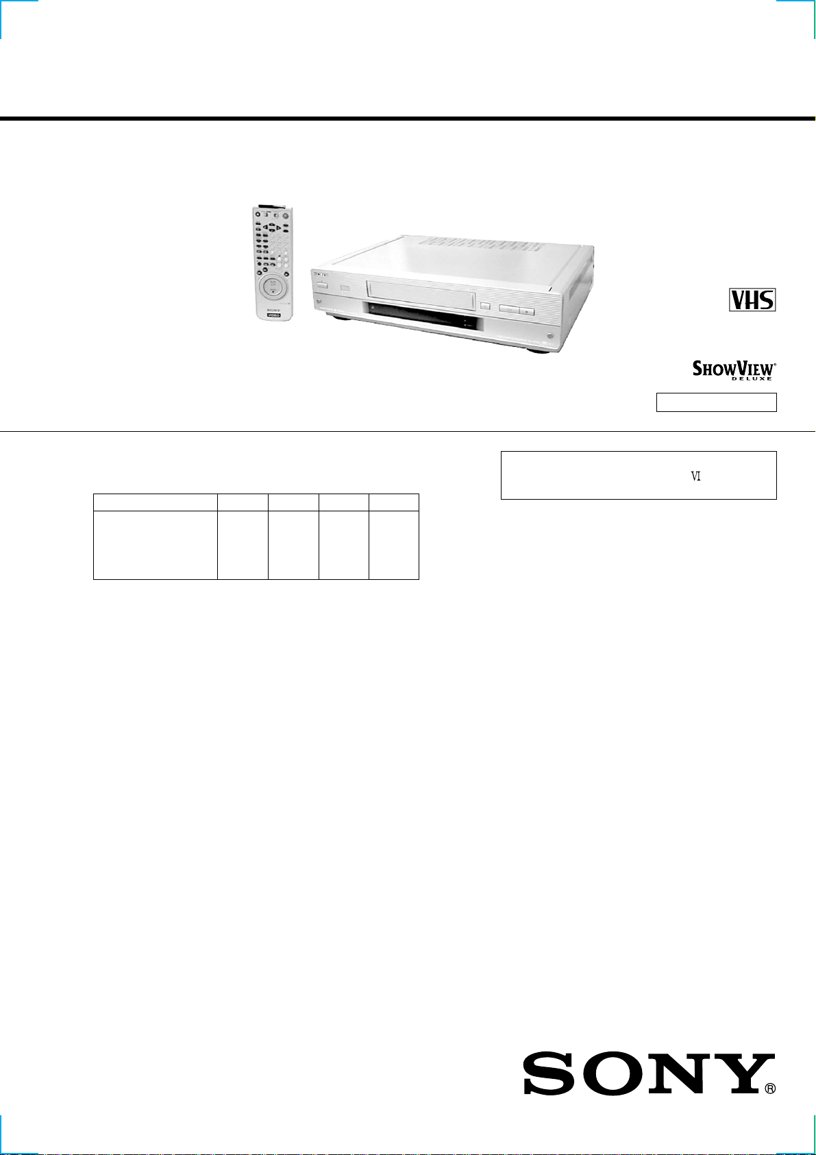
SLV-SE850/SF900/SF950/SF990
RMT-V259M/V259N/V259P/V259Q/V260C/V260D
SERVICE MANUAL
Photo : SL V -SE990
RMT-V260D
The abbreviations of SE850/SF900/SF950/SF990 contained in this service manual
are indicated when these models are common to all their corresponding models as
given below.
Abbreviated models name
All models name
SLV-
SE850
SE850B
SE850D
SE850E
SE850G
SF900
SF900B
SF900D
SF900E
SF900G
SF950
SF950N
SF990
SF990B
SF990D
SF990E
SF990G
AEP Model
SLV-SE850/SF900/SF950/SF990
UK Model
SLV-SE850/SF900/SF990
G
SR MECHANISM
Refer to the SERVICE MANUAL of VHS
MECHANICAL ADJUSTMENT
MECHANICAL ADJUSTMENTS. (9-921-647-11)
for
System
Channel coverage
PA
L (B/G): SE850D,E,G/SF900D,E,G/
VHF E2 to E12
VHF Italian channel A to H
UHF E21 to E69
CATV S01 to S05, S1 to S20
HYPER S21 to S41
SECAM (L): SE850B/SF900B/SF990B
VHF F2 to F10
UHF F21 to F 69
CATV B to Q
HYPER S21 to S41
R
F output signal
UHF channels 21 to 69
Aerial out
75-ohm asymmetrical aerial socket
Tape speed
SP: PAL 23,39 mm/s (recording/playback)
LP: PAL11,70 mm/s (recording/playback)
EP: NTSC 11,12 mm/s (playback only)
SF950/SF990D,E,G
NT
SC 33,35 mm/s (playback only)
SECAM 23,39mm/s (recording/playback)
(SE850B/SF900B/SF990B only)
NTSC 16,67 mm/s (playback only)
SECAM 11,70mm/s (recording/playback)
(SE850B/SF900B/SF990B only)
SPECIFICATIONS
Maximum recording/playback time
10 hrs. in LP mode (with E300 tape)
Fast-forward and rewind time
Approx. 1 min. (with E180 tape)
Inputs and outputs
Li INE-1 (TV)
21-pin
Video input: pin 20
Audio input: pins 2 and 6
Video output: pin 19
Audio output: pins 1 and 3
DECODER/t LINE-3 IN (SE850/SF900/SF950 only)/
LINE-4 IN (SF990 only)
21-pin
Video input: pin 20
Audio input: pins 2 and 6
LINE-2 IN
VIDEO IN, phono jack (1)
Input signal: 1 Vp-p, 75 ohms, unbalanced, sync
negative
AUDIO IN, phono jack (2)
Input level: 327 mVrms
Input impedance : more than 47 kilohms
VIDEO CASSETTE RECORDER
LINE-3 IN (SF990 only)
VIDEO IN, phono jack (1)
Input signal: 1 Vp-p, 75 ohms, unbalanced, sync
negative
AUDIO IN, phono jack (2)
Input level: 327 mVrms
Input impedance : more than 47 kilohms
LINE-2 OUT
VIDEO OUT, phono jack (1)(SF950/SF990 only)
Output signal: 1 Vp-p, 75 ohms, unbalanced, sync
negative
AUDIO OUT, phono jack (2)
Rated output level: 327 mVrms
Load impedance: 47 kilohms
Output impedance: less than 10 kilohms
— Continued on next page —

General
Power requirements
220 – 240 V AC, 50 Hz
Power consumption
25 W (Normal)(SF900/SF950/SF990 only)
23 W (Normal)(SE850 only)
2,
7 W (POWER SAVE is set to ON, no decoder)
(SF900/SF950/SF990 only)
2,0 W (POWER SAVE is set to ON, no decoder)
(SE850 only)
Operating temperature
5°C to 40°C
Storage temperature
–20°C to 60°C
Dimensions
Approx. 430 × 100 × 330 mm (w/h/d)
cluding projecting parts and controls
in
Mass
rox. 4.8 kg (SF900/SF950/SF990 only)
App
Approx. 4.6 kg (SE850 only)
Supplied accessories
Remote commander (1)
R6 (size AA) batteries (2)
Aerial cable (1)
SmartFile labels (5)
Set-Top Box controller (1)
Design and specifications are subject to change without
notice.
SAFETY-RELATED COMPONENT WARNING!!
COMPONENTS IDENTIFIED BY MARK 0 OR DOTTED LINE WITH
MARK 0 ON THE SCHEMATIC DIAGRAMS AND IN THE PARTS
LIST ARE CRITICAL TO SAFE OPERATION. REPLACE THESE
COMPONENTS WITH SONY PARTS WHOSE PART NUMBERS
APPEAR AS SHOWN IN THIS MANUAL OR IN SUPPLEMENTS
PUBLISHED BY SONY.
SAFETY CHECK-OUT
After correcting the original service problem, perform the following
safety checks before releasing the set to the customer.
1. Check the area of your repair for unsoldered or poorly-soldered
connections. Check the entire board surface for solder splashes
and bridges.
2. Check the interboard wiring to ensure that no wires are
"pinched" or contact high-wattage resistors.
3. Look for unauthorized replacement parts, particularly
transistors, that were installed during a previous repair . Point
them out to the customer and recommend their replacement.
4. Look for parts which, through functioning, show obvious signs
of deterioration. Point them out to the customer and
recommend their replacement.
5. Check the B+ voltage to see it is at the values specified.
6. Flexible Circuit Board Repairing
• Keep the temperature of the soldering iron around 270˚C
during repairing.
• Do not touch the soldering iron on the same conductor of the
circuit board (within 3 times).
• Be careful not to apply force on the conductor when soldering
or unsoldering.
— 2 —

TABLE OF CONTENTS
SERVICE MODE
1. ERROR CODE INDICATION··········································· 5
2. EEPROM DATA INPUT ···················································· 6
1. GENERAL
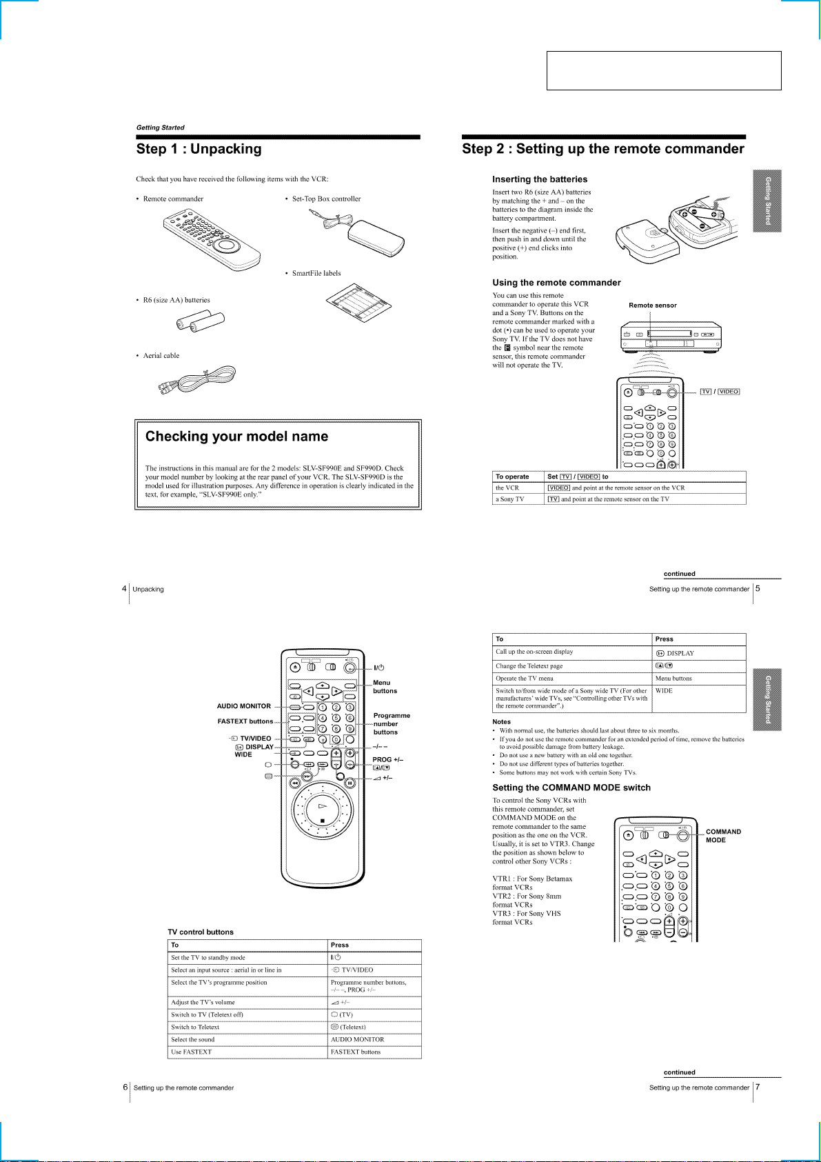
Getting Started
Step 1 : Unpacking ································································1-1
Step 2 : Setting up the remote commander ····························1-1
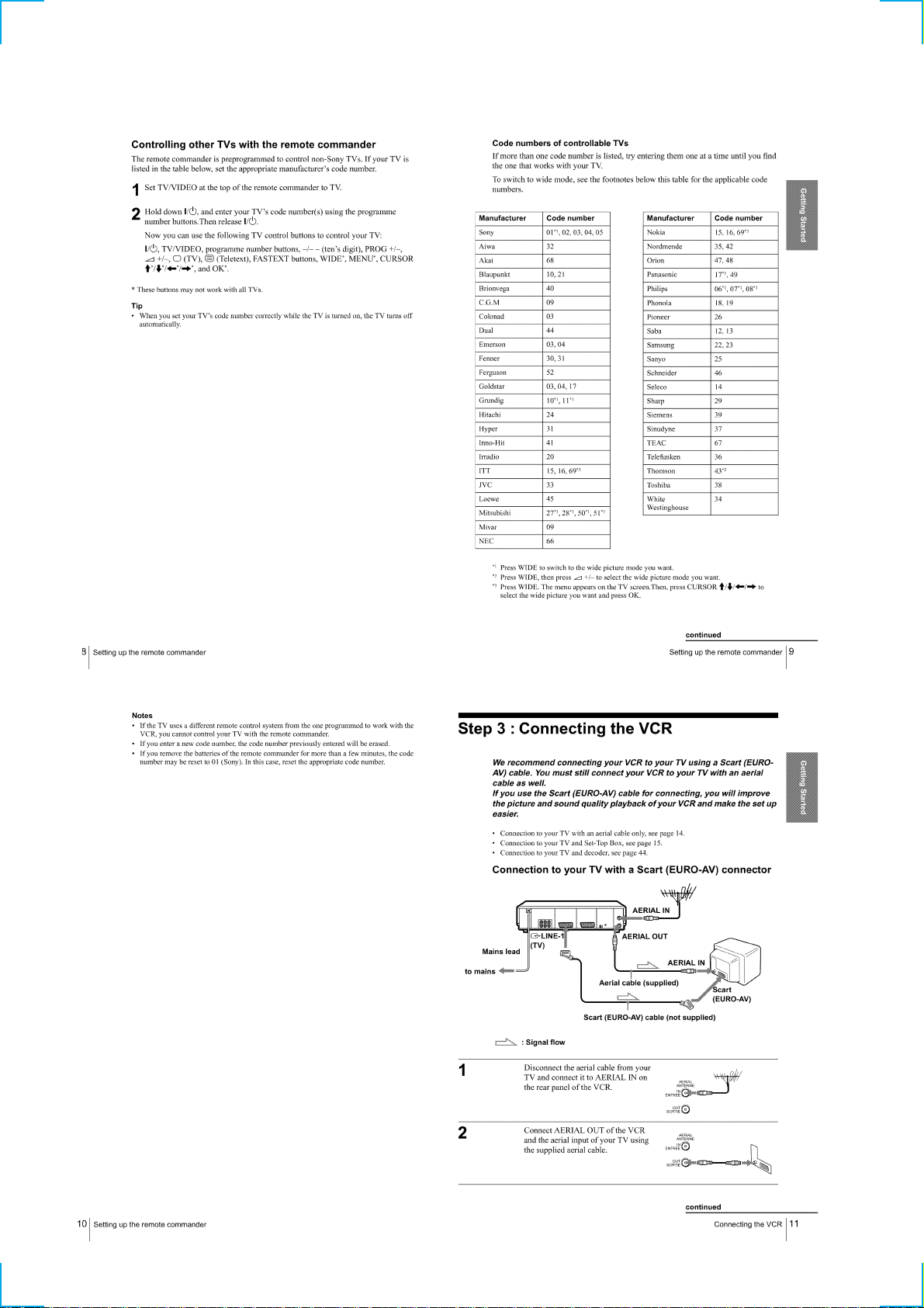
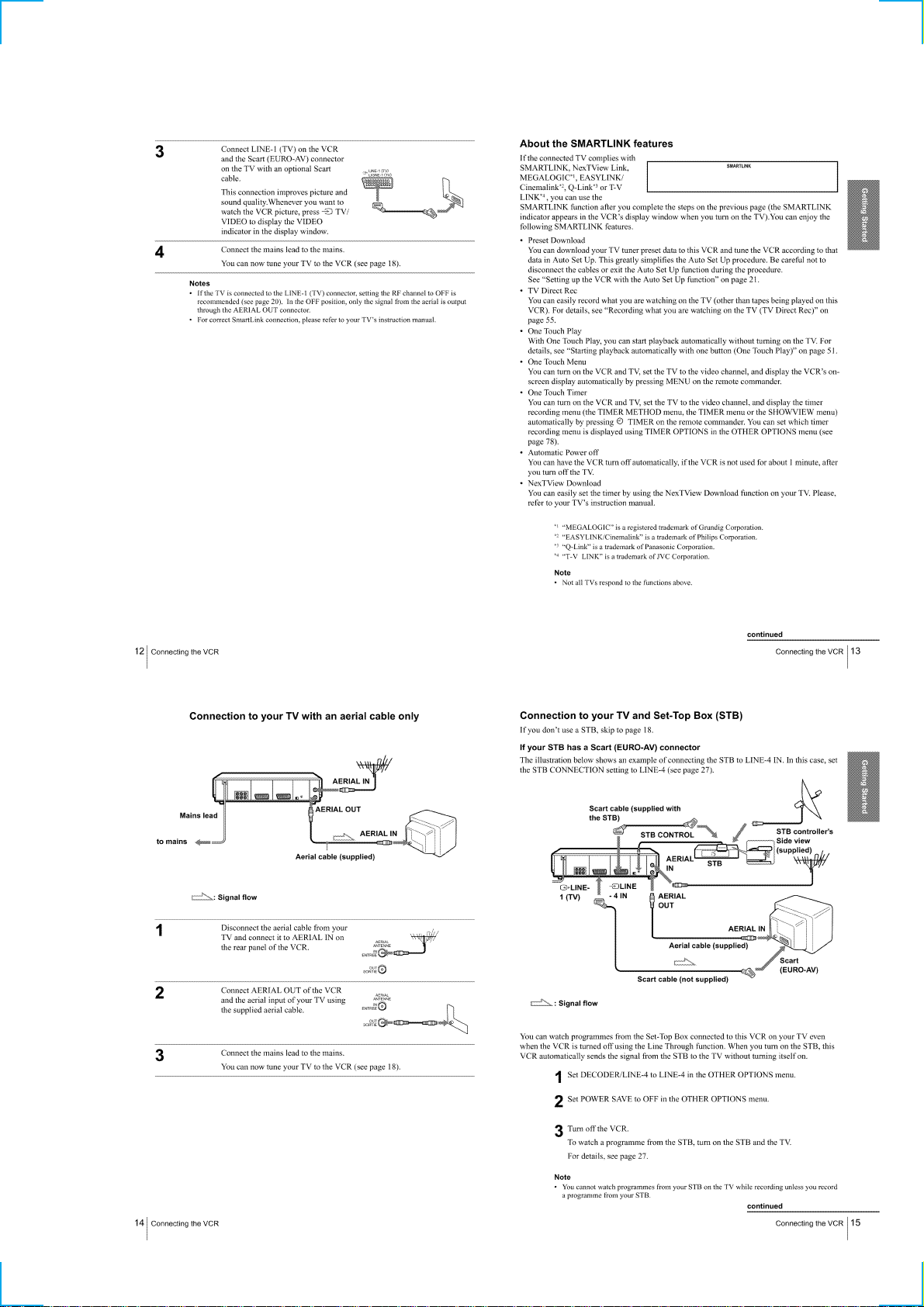
Step 3 : Connecting the VCR·················································1-2
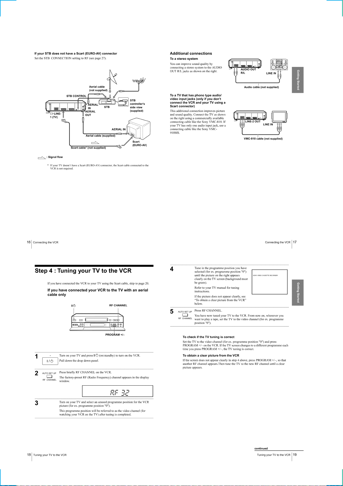
Step 4 : Tuning your TV to the VCR ·····································1-4
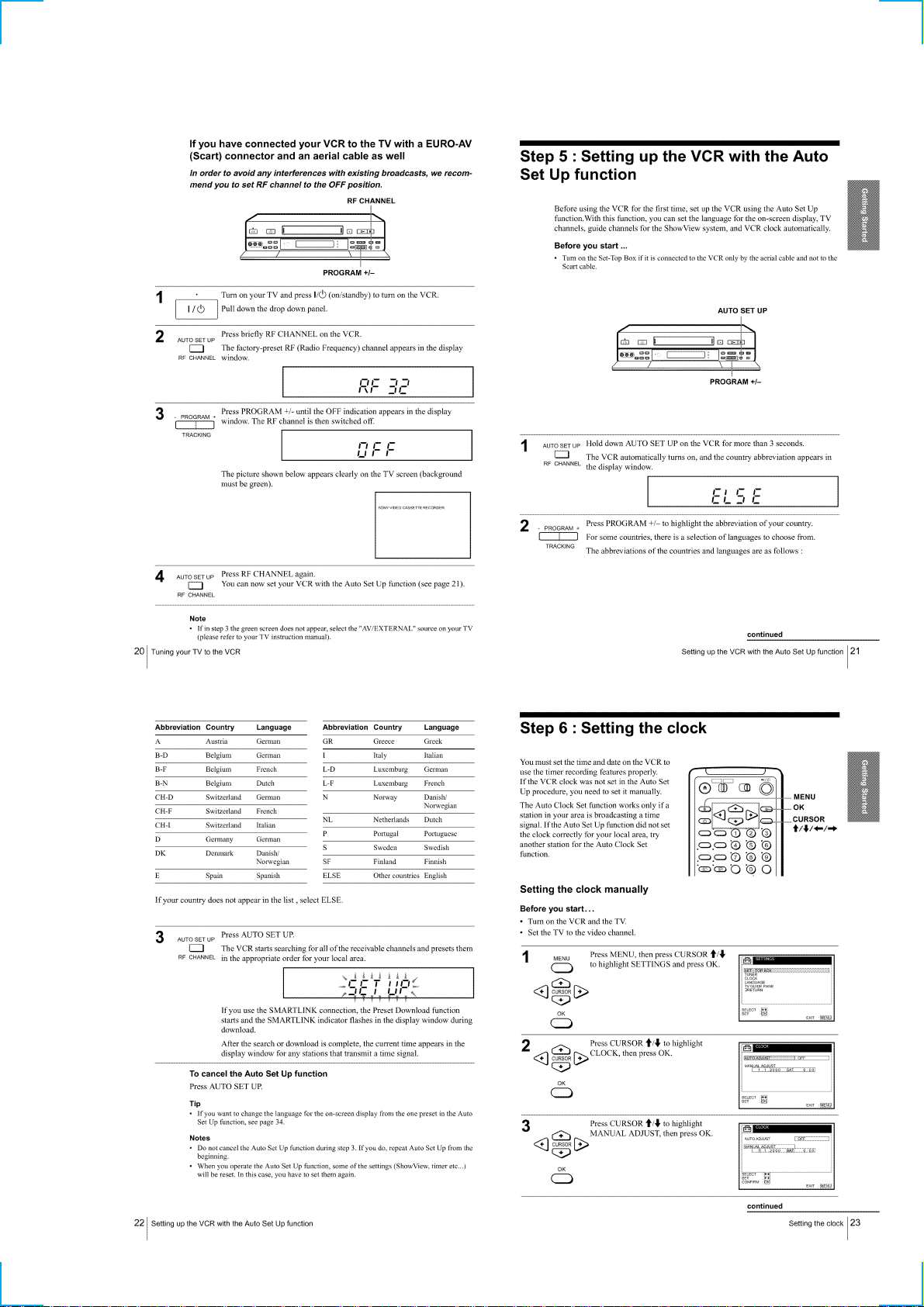
Step 5 : Setting up the VCR with the Auto Set Up function ··1-5
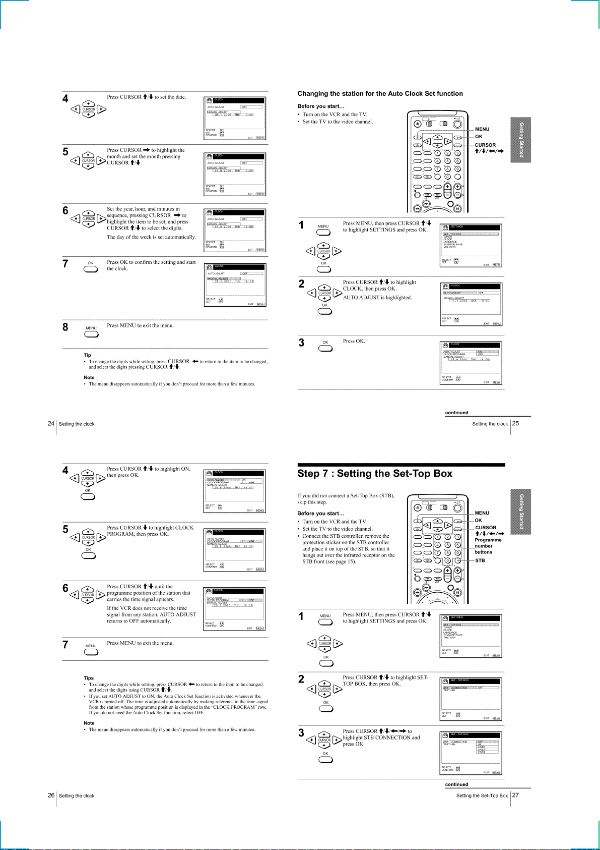
Step 6 : Setting the clock ·······················································1-5
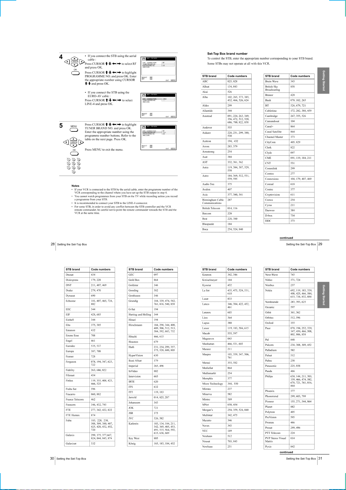
Step 7 : Setting the Set-Top Box············································1-6
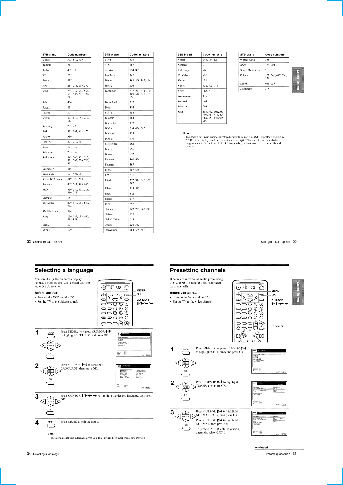
Selecting a language ······························································ 1-8
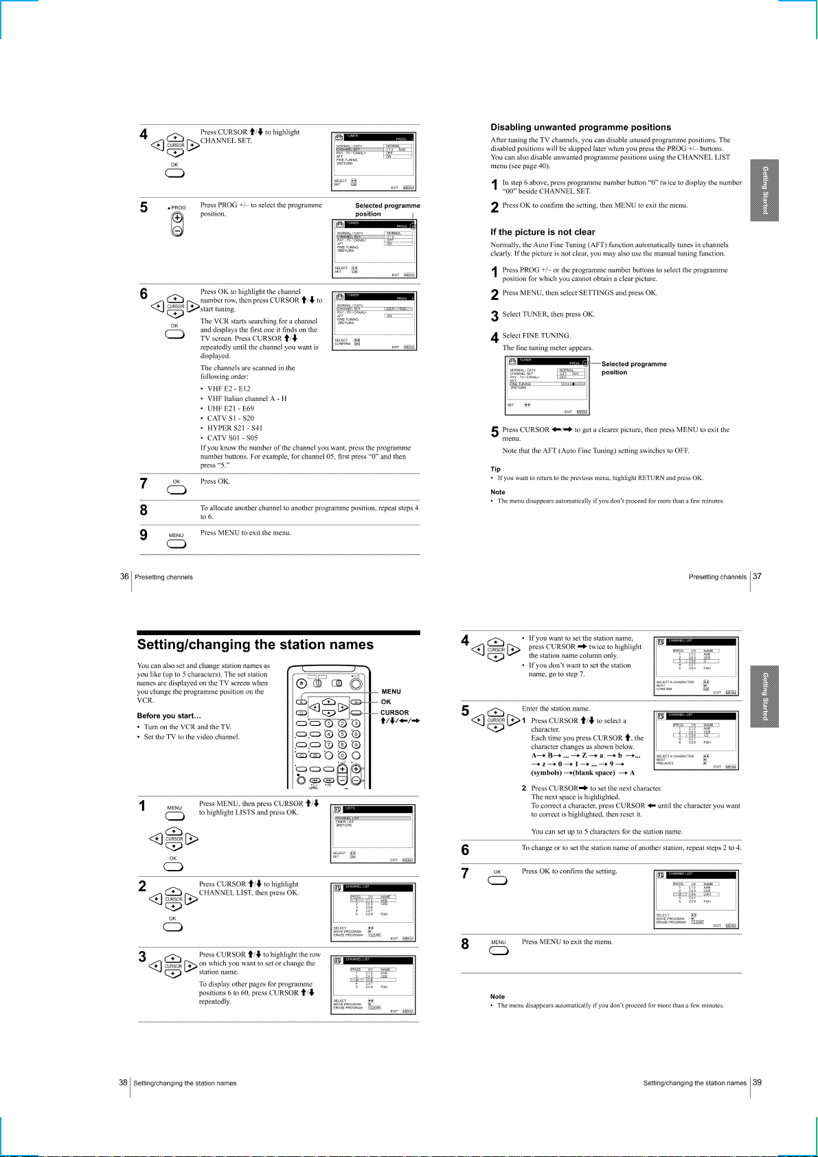
Presetting channels ································································1-8
Setting/changing the station names ·······································1-9
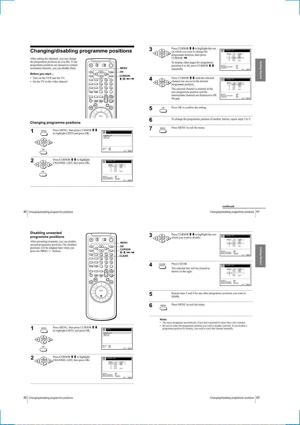
Changing/disabling programme positions ···························1-10
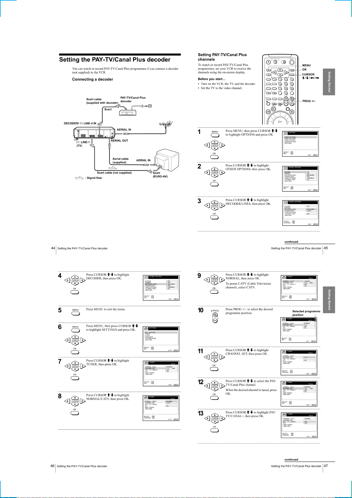
Setting the PAY-TV/Canal Plus decoder······························ 1-11
Basic Operations
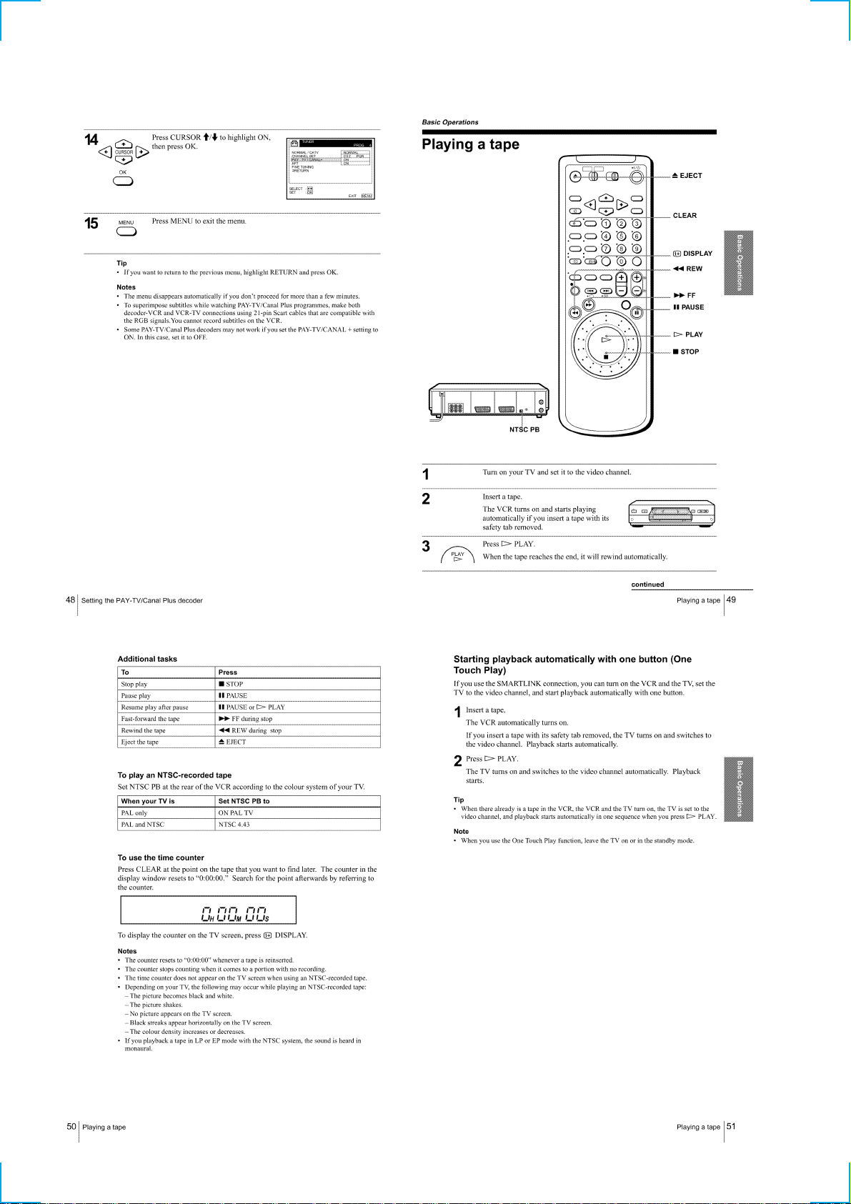
Playing a tape·······································································1-12
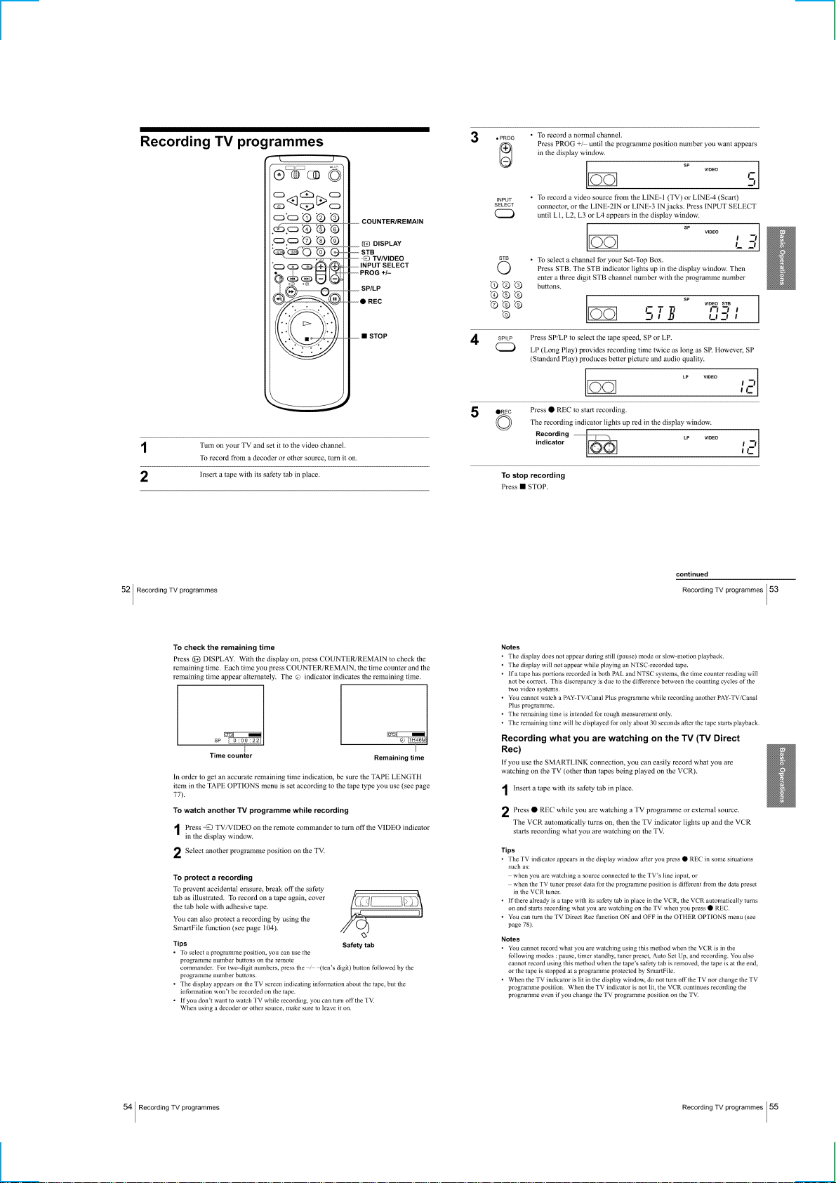
Recording TV programmes ·················································1-13
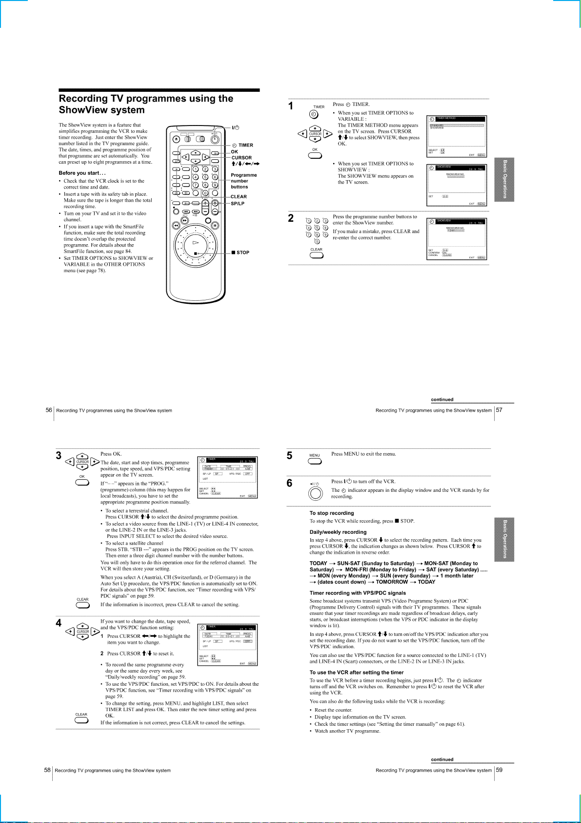
Recording TV programmes using the ShowView system ···1-14
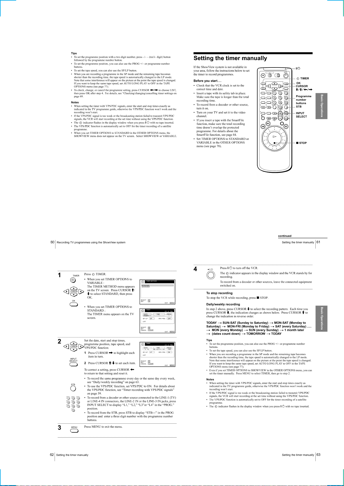
Setting the timer manually··················································· 1-15
Additional Operations
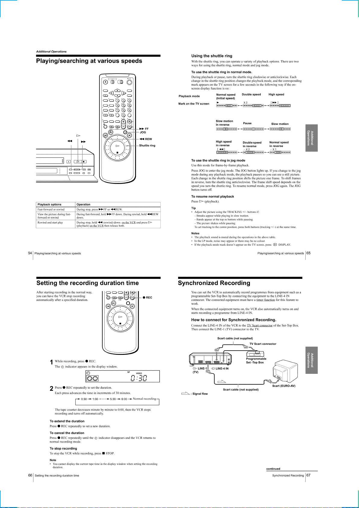
Playing/searching at various speeds ····································1-16
Setting the recording duration time ·····································1-16
Synchronized Recording······················································1-16
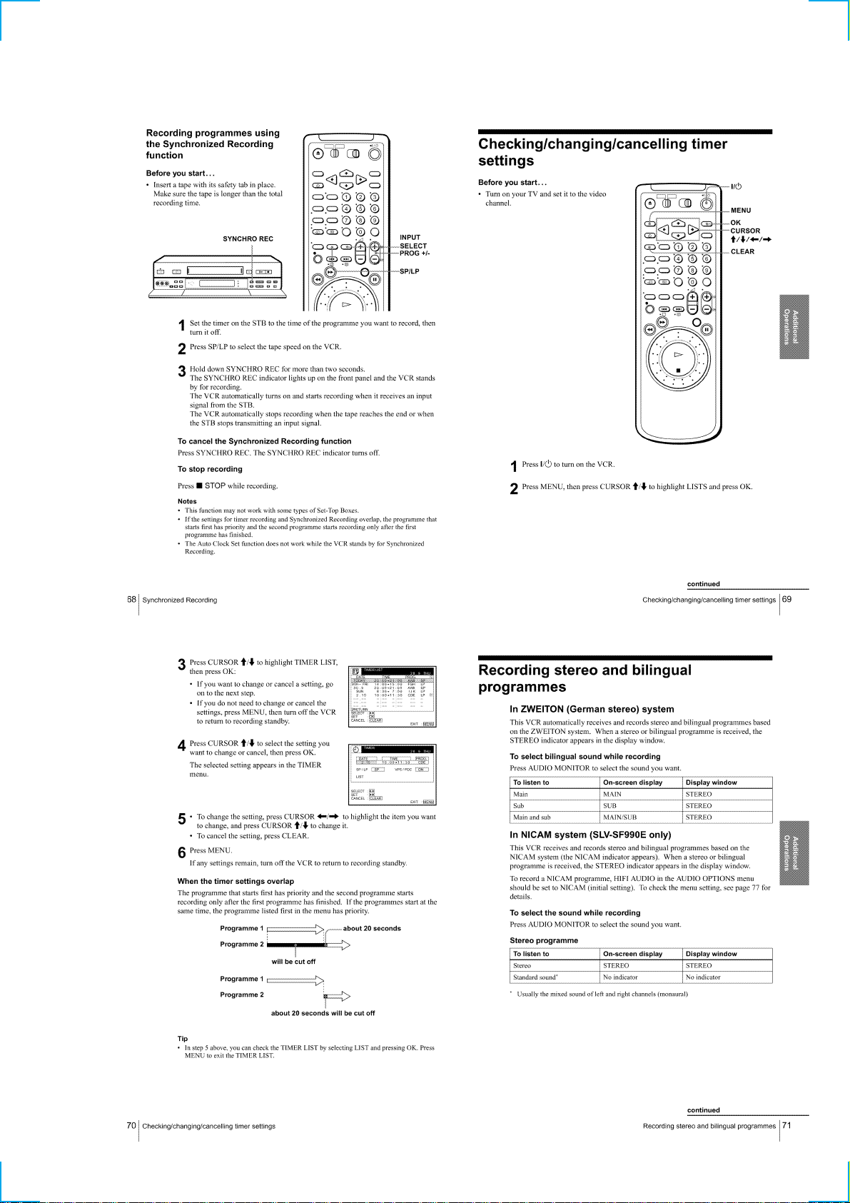
Checking/changing/cancelling timer settings ······················1-17
Recording stereo and bilingual programmes ·······················1-17
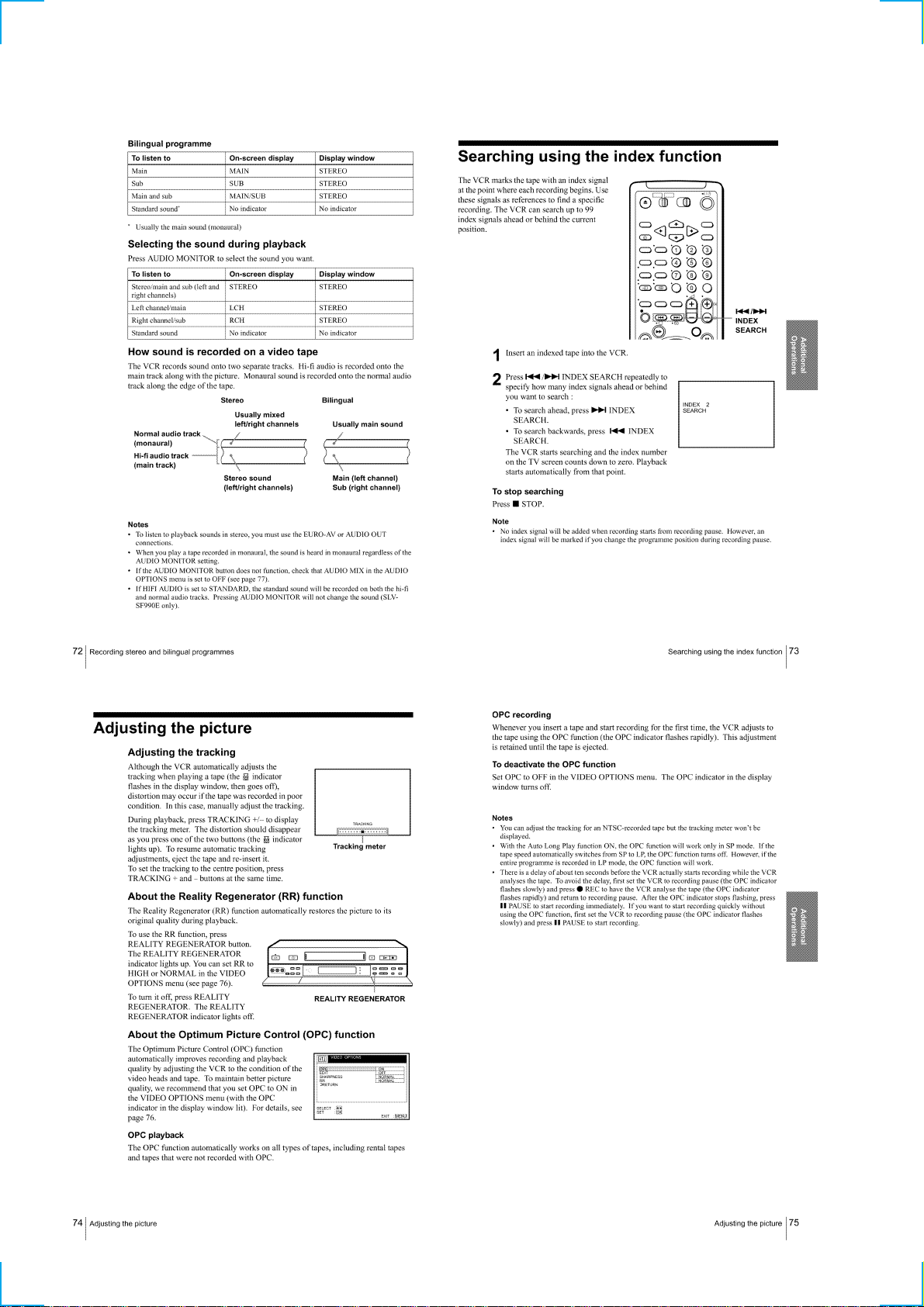
Searching using the index function······································1-18
Adjusting the picture ···························································1-18
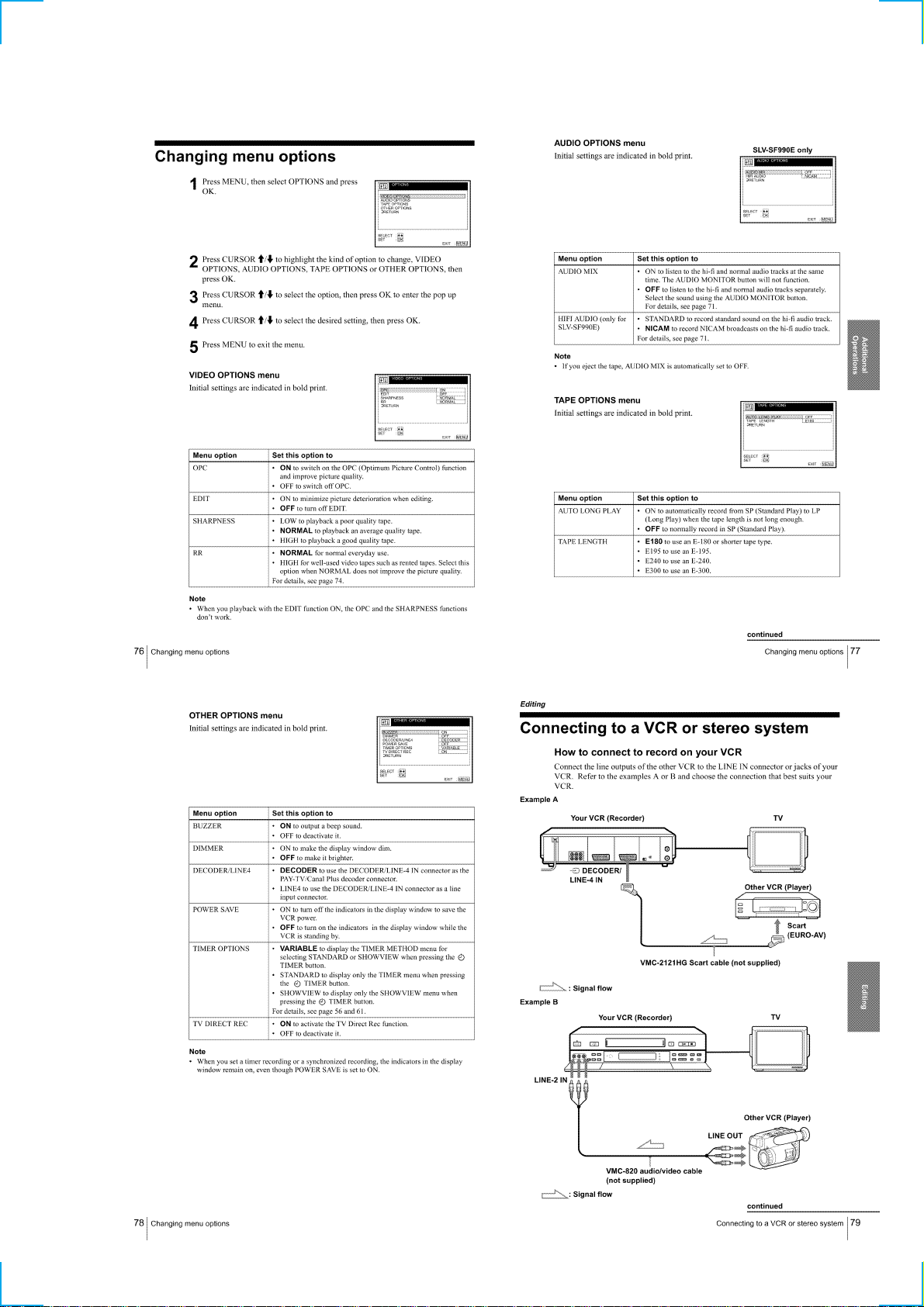
Changing menu options ·······················································1-19
Editing
Connecting to a VCR or stereo system································1-19
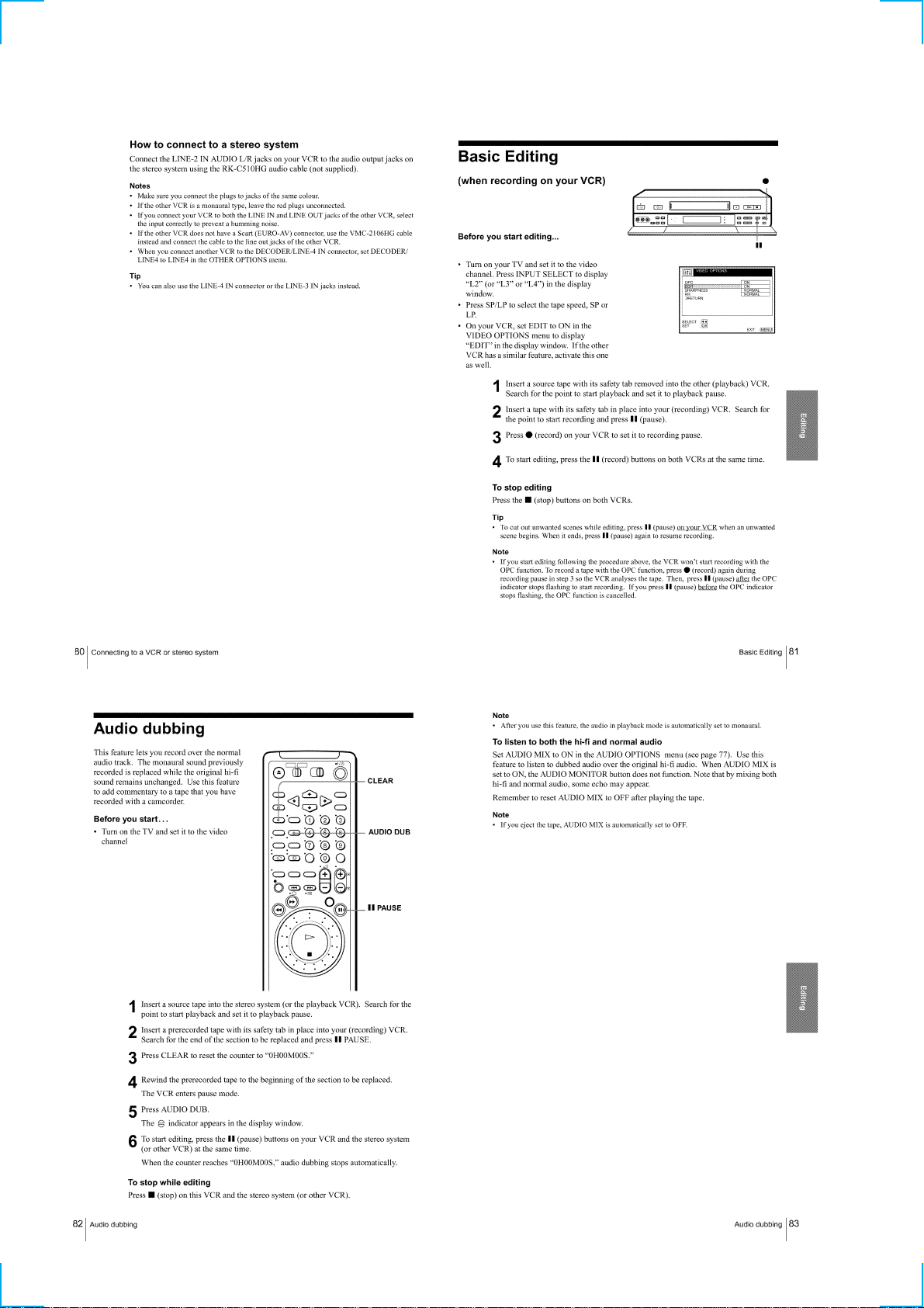
Basic Editing········································································1-20
Audio dubbing ····································································· 1-20
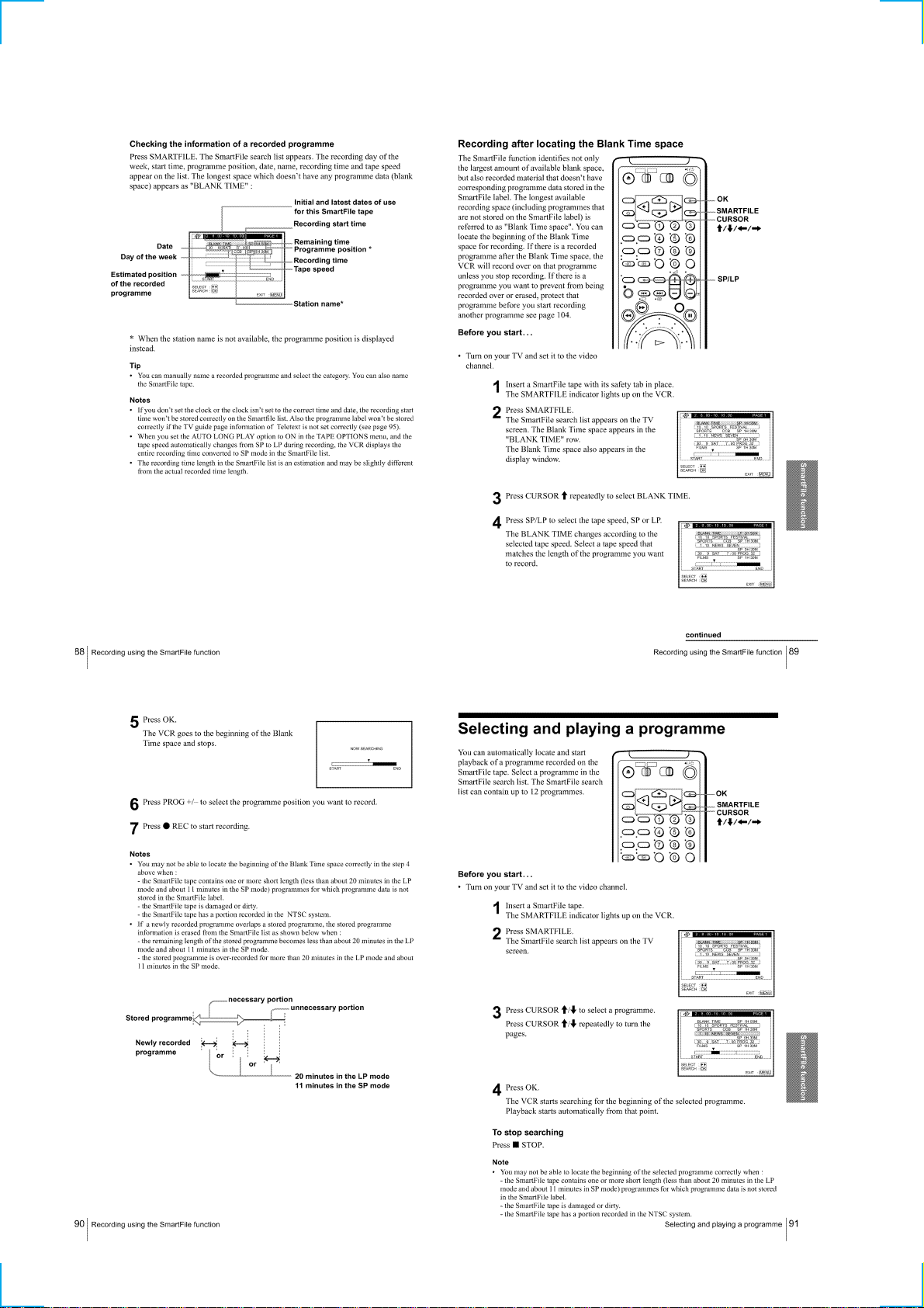
SmartFile function
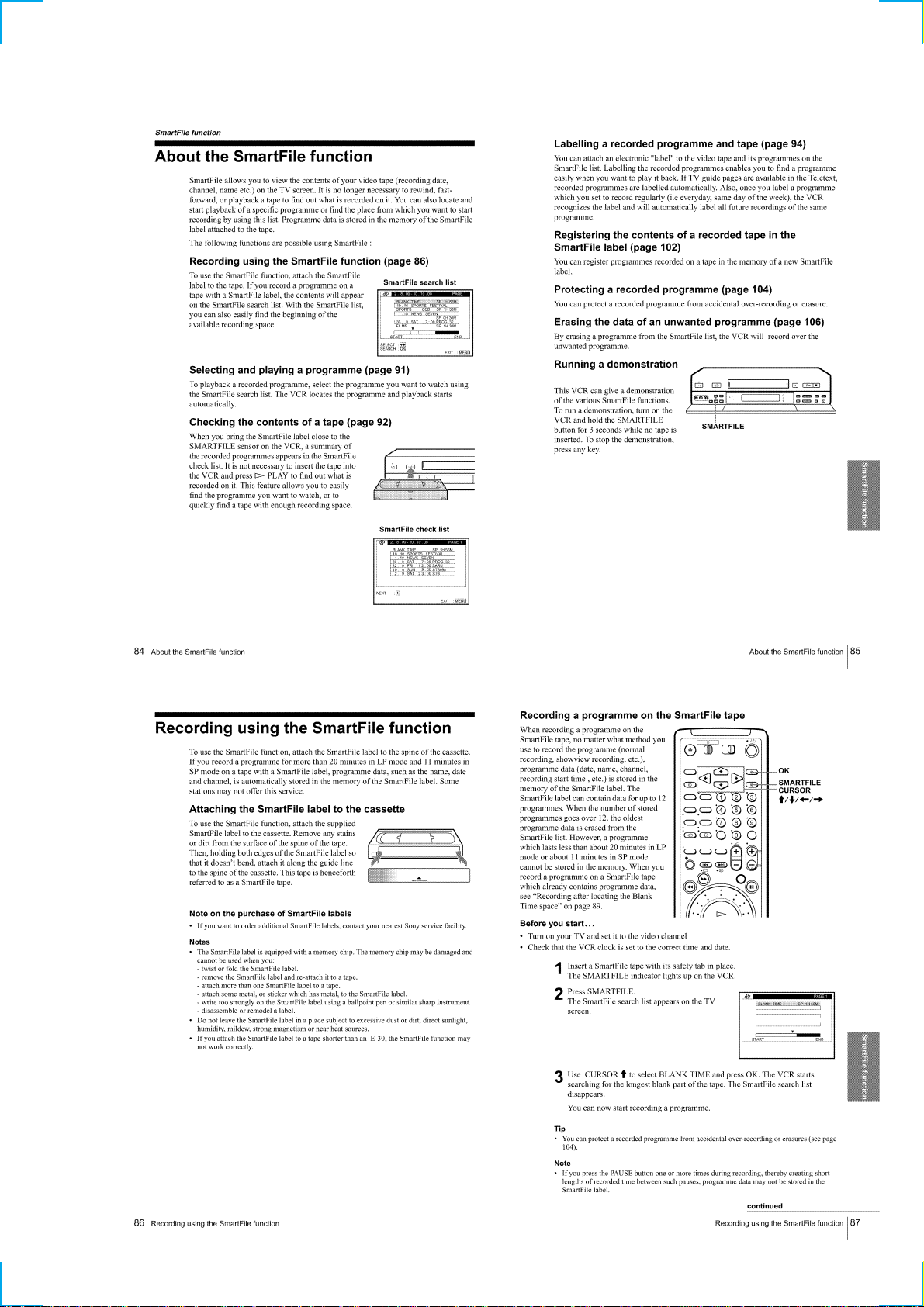
About the SmartFile function ··············································1-21
Recording using the SmartFile function ······························1-21
Selecting and playing a programme ····································1-22
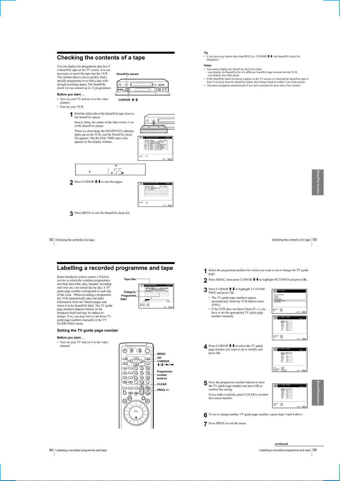
Checking the contents of a tape ···········································1-23
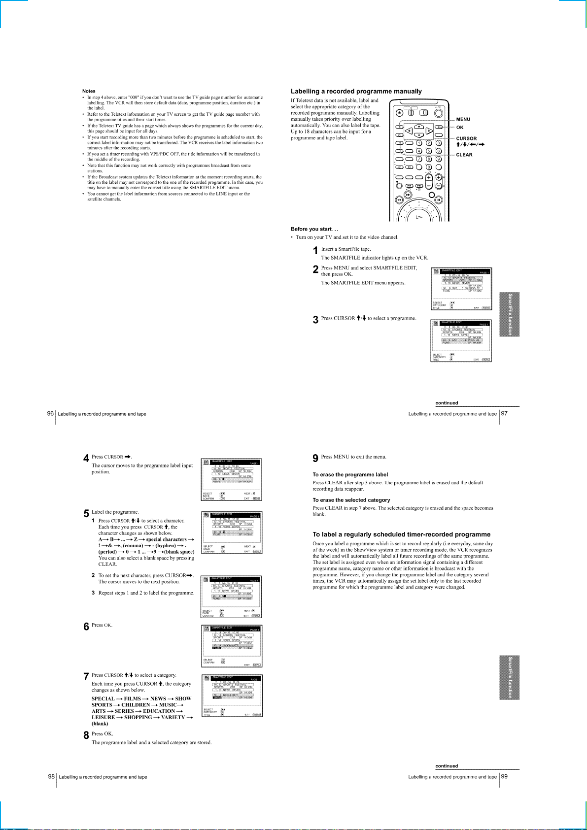
Labelling a recorded programme and tape ··························1-23
Registering the contents of a recorded tape in the
SmartFile label····································································· 1-25
Protecting a recorded programme········································1-26
Erasing the data of an unwanted programme ······················1-26
Additional Information
Troubleshooting ···································································1-27
Index to parts and controls···················································1-28
Menu chart ···········································································1-29
2. DISASSEMBLY
2-1. CASE, FRONT PANEL BLOCK ASSEMBLY ··············2-1
2-2. DM-95, FR-169, JK-195, AT-28 BOARDS ····················2-1
2-3. REAR PANEL ·································································2-2
2-4. RP-238 BOARD······························································2-2
2-5. SR MECHANISM DECK···············································2-3
2-6. POWER BLOCK, MA-388 BOARDS····························2-3
2-7. INTERNAL VIEWS························································2-4
2-8. CIRCUIT BOARDS LOCATION ···································2-5
3 BLOCK DIAGRAMS
3-1. OVERALL BLOCK DIAGRAM (1/2) ···························3-3
OVERALL BLOCK DIAGRAM (2/2) ···························3-5
3-2. VIDEO BLOCK DIAGRAM (1/2) ·································3-8
VIDEO BLOCK DIAGRAM (2/2) ·································3-9
3-3. SERVO/SYSTEM CONTROL
BLOCK DIAGRAM (1/2)·············································3-11
SERVO/SYSTEM CONTROL
BLOCK DIAGRAM (2/2)·············································3-13
3-4. AUDIO BLOCK DIAGRAM ········································3-15
3-5. SMART FILE BLOCK DIAGRAM ·····························3-17
3-6. POWER BLOCK DIAGRAM (1/2)······························3-19
POWER BLOCK DIAGRAM (2/2) ······························3-21
4. PRINTED WIRING BOARDS AND
SCHEMATIC DIAGRAMS
4-1. FRAME SCHEMATIC DIAGRAM································4-1
4-2. PRINTED WIRING BOARDS AND
SCHEMATIC DIAGRAMS ············································4-5
• MA-388 (REC/PB HEAD AMP)(1/8)
SCHEMATIC DIAGRAM ······························4-5
• MA-388 (Y/C, AUDIO PROCESSOR)(2/8)
SCHEMATIC DIAGRAM ······························4-7
• MA-388 (ON SCREEN DISPLAY)(3/8)
SCHEMATIC DIAGRAM ······························4-9
• MA-388 (SERVO/SYSTEM CONTROL)(4/8)
SCHEMATIC DIAGRAM ····························4-11
• MA-388 (INPUT/OUTPUT)(5/8)
SCHEMATIC DIAGRAM ····························4-13
• MA-388 (AUDIO)(6/8)
SCHEMATIC DIAGRAM ····························4-15
• MA-388 (TUNER)(7/8)
SCHEMATIC DIAGRAM ····························4-17
• MA-388 (POWER SUPPLY)(8/8)
SCHEMATIC DIAGRAM ····························4-19
• MA-388 (REC/PB HEAD AMP, Y/C,
AUDIO PROCESSOR, ON SCREEN DISPLAY,
SER VO/SYSTEM CONTROL, INPUT/OUTPUT,
AUDIO, TUNER, POWER SUPPLY)
PRINTED WIRING BOARD ·······················4-21
• RP-238 (BIAS)
PRINTED WIRING BOARD ·······················4-24
• RP-238 (BIAS)
SCHEMATIC DIAGRAM ····························4-25
• FR-169 (INDICATOR)
PRINTED WIRING BOARD ·······················4-27
• FR-169 (INDICATOR)
SCHEMATIC DIAGRAM ····························4-29
• DM-95 (USER FUNCTION)
SCHEMATIC DIAGRAM ····························4-32
• DM-95 (USER FUNCTION)
PRINTED WIRING BOARD ·······················4-33
• SE-109 (SECAM SIGNAL PROCESS)
PRINTED WIRING BOARD ·······················4-35
• SE-109 (SECAM SIGNAL PROCESS)
SCHEMATIC DIAGRAM ····························4-37
• A T-28 (LARGE ANTENNA)
PRINTED WIRING BOARD ·······················4-39
• A T-29 (SMALL ANTENNA)
PRINTED WIRING BOARD ·······················4-39
• ML-21 (SMART FILE)
PRINTED WIRING BOARD ·······················4-40
• A T-28 (LARGE ANTENNA),
AT-29 (SMALL ANTENNA),
ML-21 (SMART FILE)(1/2)
SCHEMATIC DIAGRAMS··························4-41
• ML-21 (SMART FILE)(2/2)
PRINTED WIRING BOARD ·······················4-43
• JK-195 (LINE 2 IN)
PRINTED WIRING BOARD ·······················4-45
— 3 —

• JK-195 (LINE 2 IN)
SCHEMATIC DIAGRAM ····························4-46
• POWER BLOCK (SRV939EK)
PRINTED WIRING BOARD ·······················4-47
• POWER BLOCK (SRV939EK)
SCHEMATIC DIAGRAM ····························4-49
5. INTERFACE, IC PIN FUNCTION
DESCRIPTION
5-1. SYSTEM CONTROL — VIDEO BLOCK INTERFACE
(MA-388 Board IC160)···················································5-1
5-2. SYSTEM CONTROL — SERVO PERIPHERAL
CIRCUIT INTERFACE (MA-388 Board IC160) ··········· 5-1
5-3. SYSTEM CONTROL — MECHANISM INTERFACE
(MA-388 Board IC160)···················································5-2
5-4. SYSTEM CONTROL — SYSTEM CONTROL
PERIPHERAL CIRCUIT INTERFACE
(MA-388 Board IC160)···················································5-2
5-5. SYSTEM CONTROL — AUDIO BLOCK INTERFACE
(MA-388 Board IC160)···················································5-2
5-6. SERVO/SYSTEM CONTROL MICROPROCESSOR
PIN FUNCTION
(MA-388 Board IC160 CXP8846-022Q)························5-3
5-7. MODE CONTROL MICROPROCESSOR PIN
FUNCTION
(FR-169 Board IC180 uPD703033AYGF-M02-3B) ·······5-4
5-8. SMART FILE CONTROL MICROPROCESSOR PIN
FUNCTION (ML-21 Board IC902 CXP84632-079Q) ···5-5
5-9. SMART FILE TELETEXT MICROCOMPUTER PIN
FUNCTION (ML-21 Board IC950 SDA5250M-2) ········5-6
7. REPAIR PARTS LIST
7-1. EXPLODED VIEWS ······················································7-1
7-1-1.FRONT PANEL AND UPPER CASE SECTION ··········7-2
7-1-2.CHASSIS SECTION······················································· 7-4
7-1-3.MECHANISM DECK SECTION-1 ·······························7-5
7-1-4.MECHANISM DECK SECTION-2 ·······························7-6
7-1-5.MECHANISM DECK SECTION-3 ·······························7-7
7-2. ELECTRICAL PARTS LIST ··········································7-8
6. ADJUSTMENTS
6-1. MECHANICAL ADJUSTMENT ···································6-1
6-2. ELECTRICAL ADJUSTMENT······································6-1
2-1. PREPARATION BEFORE ADJUSTMENT···················6-1
2-1-1.Equipment Required ························································6-1
2-1-2.Equipment Connection ····················································6-1
2-1-3.Setup for adjustment························································ 6-1
2-1-4.Alignment Tape ·······························································6-1
2-1-5.Input/Output Levels and impedance································6-2
2-1-6.Adjustment Sequence ······················································6-2
2-2. POWER SUPPLY CHECK ·············································6-2
2-2-1.Power Supply Voltage Check (MA-388 board) ···············6-2
2-3. SYSTEM CONTROL SYSTEM CHECK ······················6-3
2-3-1.Clock Oscillation Level Check (MA-388 board) ············6-3
2-4. SERVO SYSTEM CHECK ·············································6-3
2-4-1.RF Switching Position Check (MA-388 board) ··············6-3
2-4-2.Hi-Fi Switching Position Check (MA-388 board) ··········6-3
2-5. VIDEO SYSTEM CHECK ············································· 6-4
2-5-1.Playback Level Check (MA-388 board)··························6-4
2-5-2.Sync AGC Check (MA-388 board) ·································6-4
2-6. AUDIO SYSTEM ADJUSTMENT·································6-4
2-6-1.Hi-Fi Audio System Check (MA-388 board) ··················6-4
2-6-1-1. Overall Audio Output Level Check ·····························6-4
2-6-1-2. Overall Audio Distorsion Factor Check ······················6-5
2-6-1-3. Overall Noise Level Check··········································6-5
2-6-1-4. HiFi Audio Frequency Response Check······················6-5
2-6-1-5. Audio PB Level Check ················································6-5
2-6-2.Normal Audio System Adjustment ··································6-6
2-6-2-1. ACE Head Adjustment················································· 6-6
2-6-2-2. Frequency Response Check·········································6-6
2-6-2-3. E-E Output Level Check··············································6-6
— 4 —
SERVICE NOTE
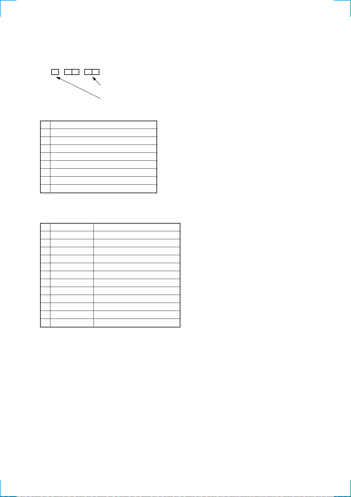
1. ERROR CODE INDICATION
• Error codes are indicated using the lower 5 digits in the fluorescent display tube.
“At this time, Colon “:” between character is not indicated.”
Mode code indication when the error has occurred.
Error code
ERROR CODE
0 No error
1 Cam encoder error Loading direction
2 Cam encoder error Unloading direction
3 T reel error
4 S reel error
5 Capstan error
6 Drum error
7 Error on initializing
8 Cassette loading error
MODE CODE
0 NC All positions other than below
1 EJECT EJECT (include Power off)
2 CDOWN Cassette down
3 ULDEND Tape unloading end • DEW stop
4 TLOAD In tape loading
5 HCLEAN In tape loading
6 LDEND Tape loading end
7 RVS RVS jog (include STILL, SLOW)
8 PR FWD, FWDP/RVS MECHA inhibit
9 FWDP FWD SLOW, FWD STILL
10 FWD PB, FWD JOG • STOP (DRUM ON)
11 STOP STOP (DRUM OFF • Power OFF)
12 FR FF/REW
— 5 —
2. EEPROM DATA INPUT
When EEPROM (IC182 on FR-169 board) is replaced with new one or “888” appears for short time on CH indicator after A C plug OFF/ON,
perform the following procedure.
8 88
Fluorescent display tube
1) Connect the adjustment remote commander (RM-95: J-6082-053-B) with CN165 of MA-388 board by using LANC jig (J-6082-051-A).
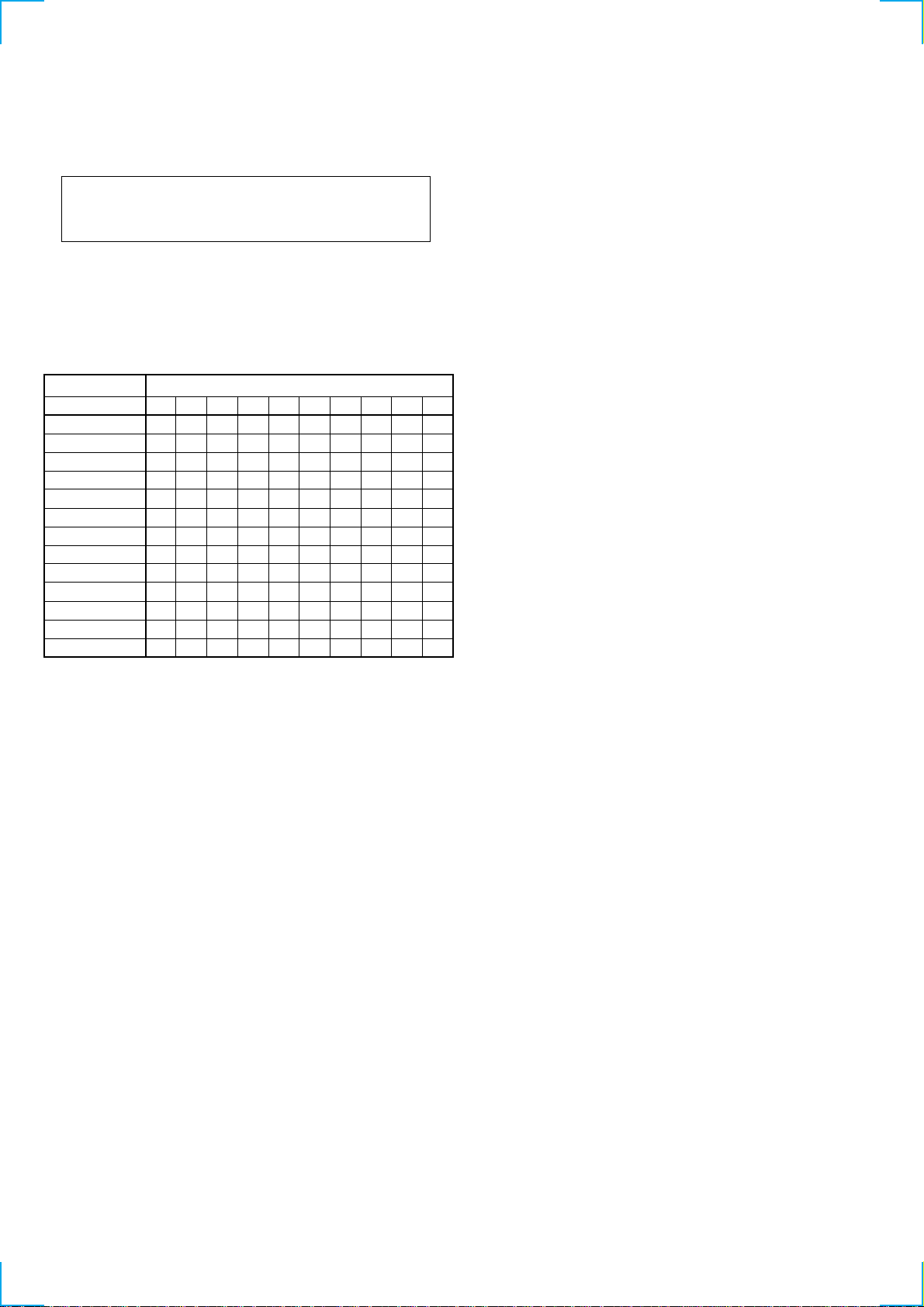
2) Select page: 1, address: 00, and input data: 80.
3) Select page: F, and input data as following table.
Page
Address
SLV-SE850B
SLV-SE850D
SLV-SE850E
SLV-SE850G
SLV-SF900B
SLV-SF900D
SLV-SF900E
SLV-SF900G
SLV-SF950N
SLV-SF990B
SLV-SF990D
SLV-SF990E
SLV-SF990G
Note: Press the PAUSE button of the adjustment remote commander each time to set the data.
02
01
00
02
03
06
05
07
08
0F
0B
0A
0C
0D
0A
95
85
85
85
95
85
85
85
A5
95
85
85
85
0B
CE
CE
CE
CE
CE
CE
CE
CE
CE
CE
CE
CE
CE
0C
20
20
20
20
20
20
20
20
20
20
20
20
20
0D
00
01
01
01
00
01
01
01
03
02
03
03
03
F
B4
BA
BB
BC
BD
25
04
8C
A0
00
20
04
8C
20
00
20
04
8C
A0
00
15
04
88
A0
00
25
04
8C
A0
00
20
04
8C
20
00
20
04
8C
A0
00
15
04
88
A0
00
20
04
8C
20
00
25
04
8C
A0
00
20
04
8C
20
00
20
04
8C
A0
00
15
04
88
A0
00
4) Turn off the power to reset.
5) Perform “RF Switching Position Adjustment” and “AF Switching Position Adjustment”.
6) Make sure whether the function of the set works normally.
— 6 —
SECTION 1
GENERAL
SLV-SE850/SF900/SF950/SF990
This section is extracted from instruction
manual. (SLV-SF990D/E model)
1-1
1-2
1-3
1-4
1-5
1-6
1-7
1-8
1-9
1-10
1-11
1-12
1-13
1-14
1-15
1-16
1-17
1-18
1-19
1-20
1-21
1-22
1-23
1-24
 Loading...