

Sony SLV-SE210B, SLV-SE210D, SLV-SE210G, SLV-SX110A, SLV-SX110B Service manual
Photo: SLV-SE210
SLV-SE210B/SE210D/SE210G/
SX110A/SX110B
RMT-V257D/V257E
SERVICE MANUAL
France Model
SLV-SE210B/SX110B
Italy Model
Germany Model
North Europe Model
SLV-SE210D/SX110A
UK Model
SLV-SE210G
VIDEO CASSETTE RECORDER
SPECIFICATIONS
Refer to the SERVICE MANUAL of VHS
MECHANICAL ADJUSTMENT MANUAL
VII for MECHANICAL ADJUSTMENTS.
(9-921-790-11)
TS-10 MECHANISM
System
Channel coverage
PAL (I): (SLV-SE210G)
UHF B21 to B69
PAL (B/G)
(SLV-SE210B/SE210D/SX110B/
SX110A):
VHF E2 to E12
Italiens VHF A to H
UHF E21 to E69
CATV S01 to S05, S1 to S20
HYPER S21 to S41
SECAM (L)
(SLV-SE210B/SX110B):
VHF F2 to F10
UHF F21 to F69
CATV B to Q
HYPER S21 to S41
RF output signal
(SLV-SE210G/SE210D/SX110D)
UHF channels 21 to 69
Aerial out
75-ohm asymmetrical aerial socket
Tape speed
SP: PAL 23.39 mm/s
(recording/playback)
NTSC 33.35 mm/s
(playback only)
SECAM
(SLV-SE210B/SX110B)
23.39 mm/s
(recording/playback)
MESECAM
(SLV-SE210B/SE210D/SX110B/
SX110D)
23.39 mm/s
(recording/playback)
LP: PAL (SLV-SE210G)
11.70 mm/s
(recording/playback)
NTSC (SLV-SE210G)
16.67 mm/s
(playback only)
Maximum recording/playback time
10 hrs. in LP mode (with E300 tape)
(SLV-SE210G)
5 hrs. in SP mode (with E300 tape)
Rewind time
Approx. 60 sec. (with E180 tape)
Inputs and outputs
AV1 (EURO AV)
21-pin
Video input: pin 20
Audio input: pins 2 and 6
Video output: pin 19
Audio output: pins 1 and 3
AV2 IN (SLV-SE210B/SE210D)
21-pin
Video input: pin 20
Audio input: pins 2 and 6
General
Power requirements
240 V: (SLV-SE210G)
230 V: (SLV-SE210B/SE210D/
SX110A/SX110B)
AC, 50 Hz
Power consumption
15 W
3 W (ECO. MODE is set to ON,
Standby mode)
Operating temperature
5 C to 40 C
Storage temperature
–20 C to 60 C
Dimensions
Approx. 360 × 94 × 255 mm (w/h/d)
including projecting parts and controls
Mass
Approx. 2.8 kg (SLV-SE210G)
Approx. 2.6 kg (SLV-SE210B/
SE210D/SX110A/SX110B)
Supplied accessories
Remote commander (1)
R6 (size AA) batteries (2)
Aerial cable (1)
PERITEL cable (1)
(SLV-SE210B/SX110B)
Design and specifications are subject to
change without notice.
–2–
1. Check the area of your repair for unsoldered or poorlysoldered connections. Check the entire board surface for
solder splashes and bridges.
2. Check the interboard wiring to ensure that no wires are
"pinched" or contact high-wattage resistors.
3. Look for unauthorized replacement parts, par-ticularly
transistors, that were installed during a previous repair.
Point them out to the customer and recommend their
replacement.
4. Look for parts which, through functioning, show obvious
signs of deterioration. Point them out to the customer and
recommend their replace-ment.
5. Check the line cord for cracks and abrasion.
Recommend the replacement of any such line cord to the
customer.
6. Check the B+ voltage to see it is at the values specified.
6. Check the antenna terminals, metal trim, “metallized”
knobs, screws, and all other exposed metal parts for AC
leakage.
Check leakage as described below.
LEAKAGE TEST
The AC leakage form any exposed metal parts to earth ground
and from all exposed metal parts to any exposed metal part
having a return to chassis, must not exceed 0.5mA (500
microampers).
Leakage current can be measured by any one of three methods.
1. A commercial leakage tester, such as Simpson 229 or RCA
WT-540A. Follow the manufactures' instructions to use these
instruments.
2. A battery operated AC milliammerter. The Data Precision
245 digital multimeter is suitable for this job.
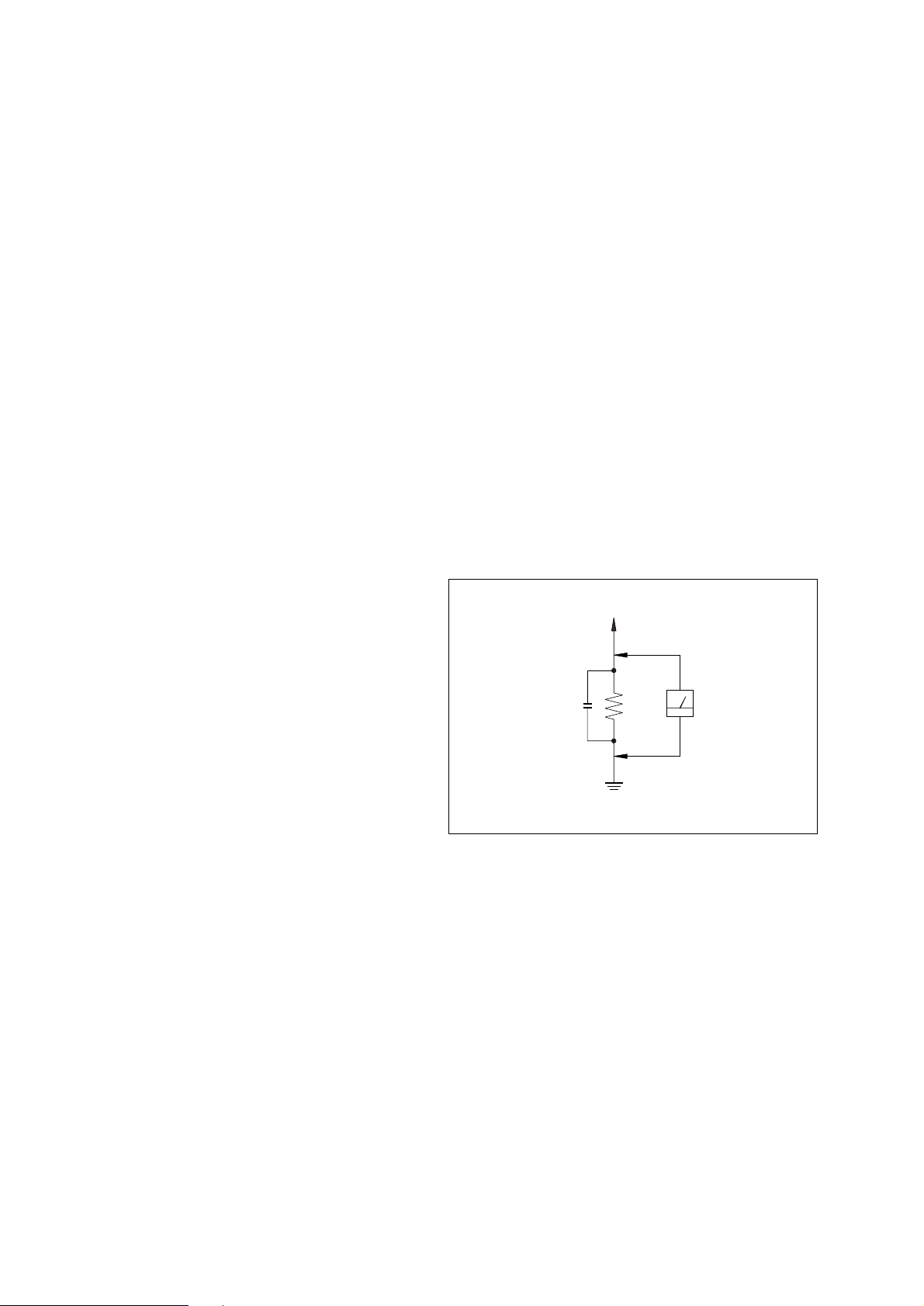
3. Measuring the voltage drop across a resistor by means of a
VOM or battery-operated AC voltmeter. The “limit”
indication is 0.75V, so analog meters must have an accurate
lowvoltage scale. The Simpson 250 and Sanwa SH-63Trd are
examples of a passive VOM that is suitable. Nearly all battery
operated digital multimeters that have a 2V AC range are
suitable. (See Fig. A)
SAFETY CHECK-OUT
After correcting the original service problem, perform the following
safety checks before releasing the set to the customer.
SAFETY-RELATED COMPONENT WARNING!!
COMPONENTS IDENTIFIED BY MARK ! OR DOTTED LINE
WITH MARK ! ON THE SCHEMATIC DIAGRAMS AND IN THE
PARTS LIST ARE CRITICAL TO SAFE OPERATION. REPLACE
THESE COMPONENTS WITH SONY PARTS WHOSE PART
NUMBERS APPEAR AS SHOWN IN THIS MANUAL OR IN
SUPPLEMENTS PUB-LISHED BY SONY.
T o Exposed Metal
Parts on Set
0.15 µF
1.5 kΩ
AC
Voltmeter
(0.75 V)
Earth Ground
Fig. A. Using an A C v oltmeter to check A C leakage.

–3–
TABLE OF CONTENTS
SERVICE NOTE
1. Mode Switch (Program Switch) Assembly Point ............. 4
2. How to eject the cassette tape
(If the unit does not operate on condition that tape is
inserted into housing ass'y) ............................................... 4
3. EEPROM Initialization and Discharging the Backup
Capacitor ............................................................................5
3-1. NV-RAM (EEPROM) Initialization Clear the EEPROM
Using the TEST Button on the JIG Remote Controller......5
3-2. NV-RAM (EEPROM) Initialization Clear the EEPROM
without Using the TEST Button on the JIG Remote
Controller............................................................................5
3-3. MICOM RESET (Backup Release)...................................5
4. How to troubleshoot ......................................................... 6
1. GENERAL
Getting Started
Index of parts and controls....................................................1-1
Step 1: Unpacking.................................................................1-2
Step 2: Setting up the remote commander.............................1-2
Step 3: Connecting the VCR.................................................1-3
Step 4: Setting up the VCR with the Auto Set Up function..1-3
Selecting a language..............................................................1-4
Presetting channels................................................................1-4
Changing/disabling programme positions.............................1-5
Setting the clock....................................................................1-6
Basic Operations
Playing a tape ........................................................................1-6
Recording TV programmes...................................................1-7
Recording TV programmes using
the VIDEO Plus+ system .................................................1-8
Setting the timer manually ....................................................1-9
Additional Operations
Playing/searching at various speeds......................................1-9
Setting the recording duration time.....................................1-10
Checking/changing/cancelling timer settings......................1-10
Adjusting the picture...........................................................1-10
Changing menu options.......................................................1-11
Editing with another VCR...................................................1-11
Additional Information
Troubleshooting...................................................................1-12
2. DISASSEMBLY
2-1. Cabinet Top ................................................................... 2-1
2-2. Cover Bottom ................................................................ 2-1
2-3. Ass’y-Panel Front .......................................................... 2-2
2-4. Ass’y MAIN-PCB, DECK ............................................ 2-3
2-5. Internal Views ............................................................... 2-4
3. PRINTED WIRING BOARDS
3-1. Main PCB ...................................................................... 3-1
4. SCHEMATIC DIAGRAMS
Block Identification of Main PCB ............................................ 4-1
4-1. S.M.P.S. ........................................................................ 4-3
4-2. Power ............................................................................ 4-5
4-3. System Control/Servo ................................................... 4-7
4-4. Audio/Video .................................................................. 4-9
4-5. TM-Block .....................................................................4-11
4-6. OSD (VPS/PDC) ......................................................... 4-13
4-7 SECAM (SLV-SE210B/SX110B model).....................4-15
4-8. Input-Output (2 Scart Jack) ......................................... 4-17
4-9. Input-Output (1 Scart Jack) ......................................... 4-19
5. ALIGNMENT AND ADJUSTMENT
5-1. Reference .......................................................................5-1
5-1-1 Location of adjustment button of remote control .......... 5-1
5-1-2. Test point location for adjustment mode setting ........... 5-2
5-2. Mechanical Adjustment ................................................ 5-3
5-2-1. The number and position of test point .......................... 5-3
5-2-2. ACE Head Position (X-Point) Adjustment ................... 5-3
5-3. Head Switching Point Adjustment ................................ 5-4
5-4. NVRAM Option Setting ............................................... 5-4
6. REPAIR PARTS LIST
6-1. Exploded Views ............................................................ 6-1
6-1-1. Instrument Assembly .................................................... 6-1
6-1-2. Mechanical Parts (Top Side) ......................................... 6-2
6-1-3. Mechanical Parts (Bottom Side) ................................... 6-3
6-2. Electrical Parts List ....................................................... 6-4
–4–
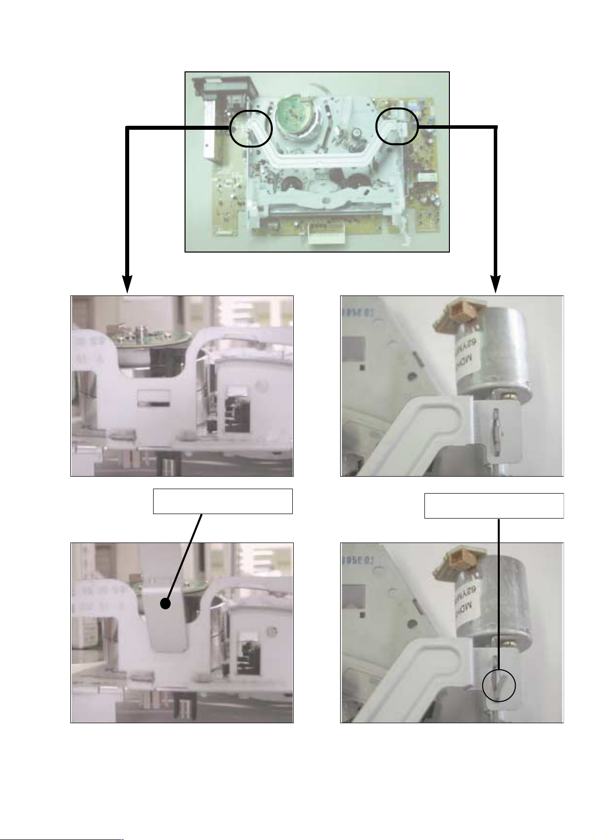
SERVICE NOTE
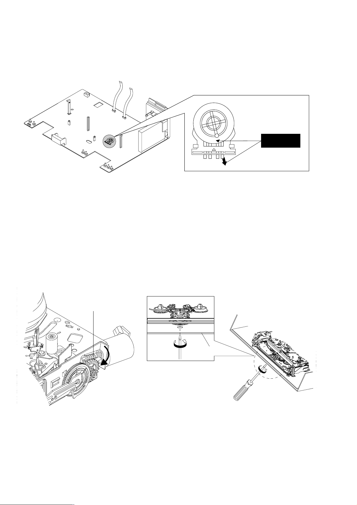
1. MODE SWITCH (PROGRAM SWITCH) ASSEMBLY POINT
1) When installing the ass’y deck on the Main PCB, be sure to align the assembly point of mode switch.
ASSEMBLY POINT
(ALIGN TWO ARROWS)
Fig. 1
2. HOW TO EJECT THE CASSETTE TAPE
(If the unit does not operate on condition that tape is inserted into housing ass’y)
1) Turn the Gear Worm Πclockwise in the direction of arrow with screw driver. (See Fig. 2)
(Other method ; Remove the screw of Motor Load Ass’y, Separate the Motor Load Ass’y)
2) When Slider S, T are approached in the position of unloading, rotate holder Clutch counterclockwise after inserting screw driver in the
hole of frame’s bottom in order to wind the unwiunded tape. (Refer to Fig. 3)
(If you rotate Gear Worm Πcontinuously when tape is in state of unwinding, you may cause a tape contamination by grease and
Fig. 2 Fig. 3
ΠGEAR WORM
FRAME
–5–
3. EEPROM INITIALIZATION AND DISCHARGING THE BACKUP CAPACITOR
3-1. NV-RAM (EEPROM) Initialization Clear the EEPROM Using the TEST Button on the JIG Remote Controller
1) Plug the VCR into the mains.
Switch on the VCR by pressing (ON/STANDBY) on the remote controller.
2) Press (TEST) button on the JIG remote controller and released.
3) Within 2 seconds, press the (CLEAR) button on the remote controller.
Result: The EEPROM will be cleared.
4) During the clearing, the “TEST” indication flashes on the front of the VCR.
The process will finish after a few seconds.(2-3 seconds)
5) After exiting the display “TEST” to normal display.
6) Press the (ON/STANDBY) button to switch off the VCR.
7) Disconnect the power supply the VCR.
It is important that you make sure ;
Do not plug the VCR into the mains after clearing EEPROM to ensure that Auto set up procedure works correctry for end users.
3-2. NV-RAM (EEPROM) Initialization Clear the EEPROM without Using the TEST Button on the JIG Remote Controller
1) Plug the VCR into the mains.
Switch on the VCR by pressing (ON/STANDBY) on the remote controller.
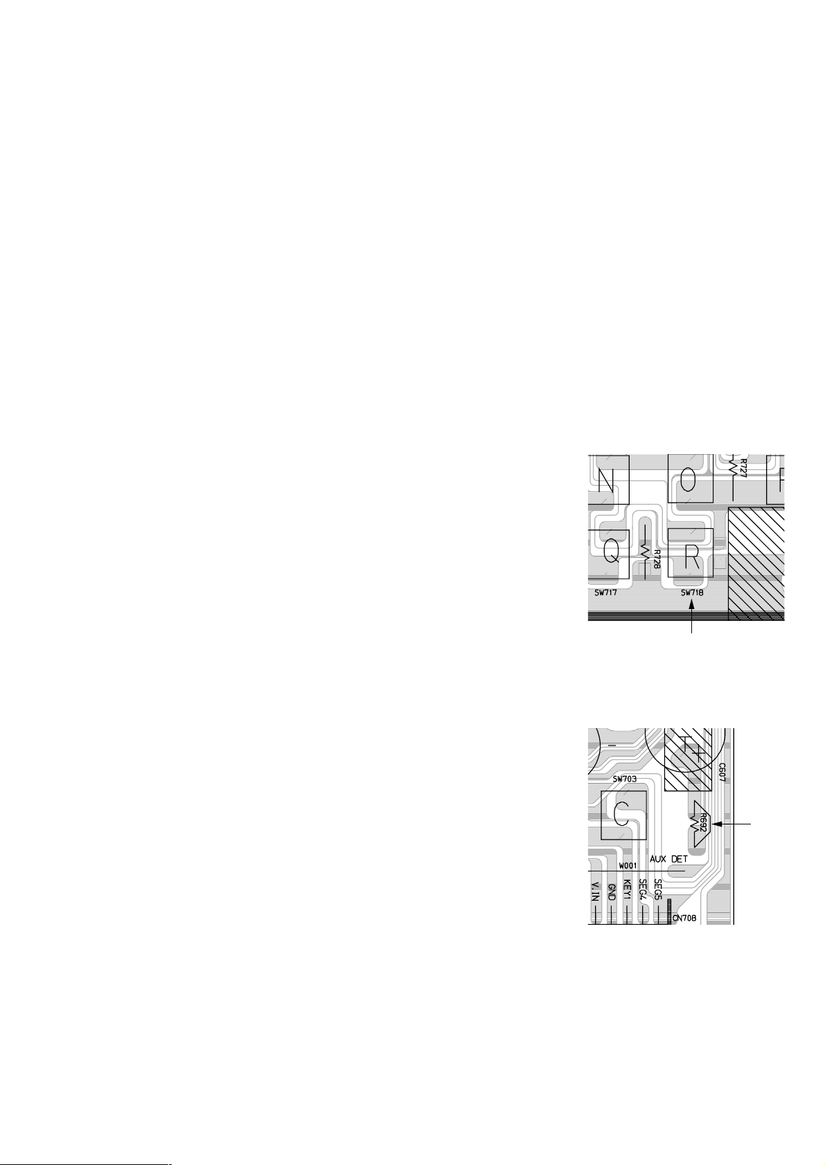
2) Press the TACT switch (SW718) on the main PCB and released.
3) Within 2 seconds, press the (CLEAR) button on the remote controller.
Result: The EEPROM will be cleared.
4) During the clearing, the “TEST” indication flashes on the front of the VCR.
The process will finish after a few seconds.(2-3 seconds)
5) After exiting the display “TEST” to normal display.
6) Press the (ON/STANDBY) button to switch off the VCR.
7) Disconnect the power supply the VCR.
It is important that you make sure ;
Do not plug the VCR into the mains after clearing EEPROM to ensure that Auto set up procedure works correctry for end users.
3-3. MICOM RESET (Backup Release)
The automatic adjustment cannot be executed unless the backup battery is discharged even if the
memory is initialized.
Release the backup power as follows only when the adjustment is going to be mode in an ealier
time after the power is turned off.
1) Open the Top cabinet.
2) Short the R692 to TU Shield GND for a few seconds. (1 or 2 seconds)
3) Now the VCR all cleared EEPROM and reseted MICOM same as factory pre-set.
R692
SW718
–6–
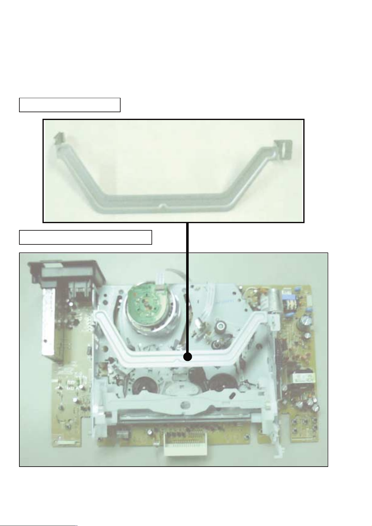
4. HOW TO TROUBLESHOOT
Circuit board check jig
Bracket-Handling: Part No. 3-067-793-01
How to use the jig: When you want to check the conductor side of the Main board, attch the jig first and the turn over the
MD Ass’y and the Main board.
BRACKET-HANDLING
Assembly of Bracket-Handling
–7–
BRACKET-HANDLING
Twist

–8–
MEMO
Getting Started
5
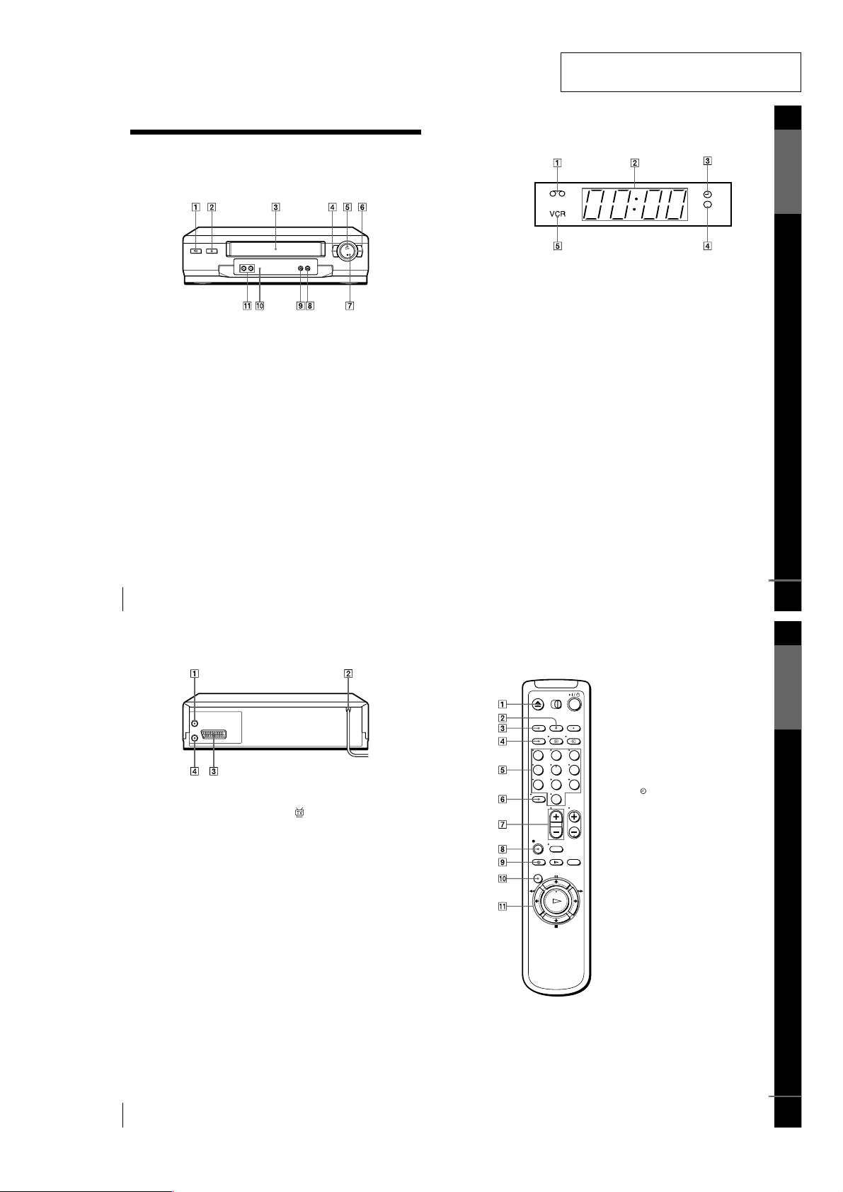
Index to parts and controls
Display window
ATape indicator (35)
BTime counter/clock/line/programme
position indicator (27) (29) (47)
CTimer indicator (33) (37)
DRecording indicator (29)
EVCR indicator (13) (30)
continued
Getting Started
7
Index to parts and controls
Remote commander
AZ EJECT button (27)
BCOUNTER/REMAIN button (30)
CCLEAR button (27) (32) (41)
DSP (Standard Play)/LP (Long Play)
button (29)
EProgramme number buttons (11) (30)
F- (ten’s digit) button (11) (30)
G2 (volume) +/– buttons (for TV)
(11)
Hz REC (record) button (29) (40)
I TIMER button (32) (36)
JMENU button (25) (41)
KX PAUSE / M button (25) (27)
x STOP/m button (25) (27)
m REW (rewind)/< button (27)
(39)
M FF (fast-forward)/, button (27)
(39)
H PLAY/OK button (25) (27)
123
456
789
0
continued
6
Index to parts and controls
Rear panel
A8 IN FRONT ANT. (in front
antenna) connector (12) (13)
BMains lead (14)
CAV1 (EURO AV) connector (13) (46)
D OUT TO TV connector (12) (13)
1-1
4
Index to parts and controls
Getting Started
Index to parts and controls
Refer to the pages indicated in parentheses ( ) for details.
Front panel
A?/1 (on/standby) switch (33)
BA (eject) button (27)
CTape compartment
Dm (rewind) button (27) (39)
EH (play) button (27) (39)
FM (fast-forward) button (27) (39)
Gx (stop) button (27) (47)
HX (pause) button (27) (47)
Iz REC (record) button (29) (40) (47)
JRemote sensor (10)
KPROGRAM +/– buttons (39) (43)
SECTION 1
GENERAL
SLV-SE210B/SE210D/SE210G/SX110A/SX110B
This section is extracted from instruction
manual. (SLV-SE210G model)
1-2
8
Index to parts and controls
L[TV] / [VIDEO] remote control switch
(10)
M?/1 (on/standby) switch (11) (33)
NINPUT SELECT button (30) (37)
(47)
Ot TV/VIDEO button (11) (13) (30)
P DISPLAY button (30)
QPROG (programme) +/– buttons (11)
(29)
RWIDE button (for TV) (11)
Sy SLOW button (39)
T×2 button (39)
123
456
789
0
Getting Started
9
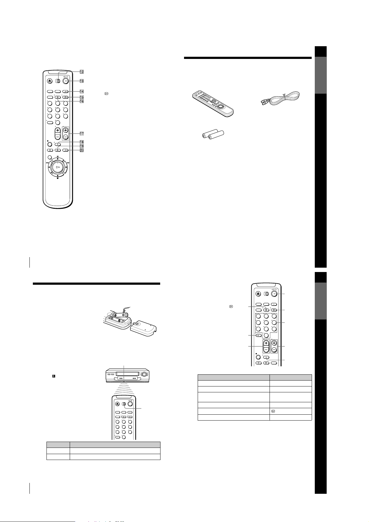
Unpacking
Step 1 : Unpacking
Check that you have received the following items with the VCR:
• Remote commander • Aerial cable
• R6 (size AA) batteries
Getting Started
11
Setting up the remote commander
TV control buttons
Notes
• With normal use, the batteries should last about three to six months.
• If you do not use the remote commander for an extended period of time, remove
the batteries to avoid possible damage from battery leakage.
• Do not use a new battery together with an old one.
• Do not use different types of batteries together.
• Some buttons may not work with certain Sony TVs.
To Press
Set the TV to standby mode ?/1
Select an input source: aerial in or line in t TV/VIDEO
Select the TV’s programme position Programme number buttons,
-, PROG +/–
Adjust the volume of the TV 2 +/–
Call up the on-screen display
DISPLAY
Switch to/from wide mode of a Sony wide TV. WIDE
123
456
789
0
Programme
number buttons
WIDE
DISPLAY
PROG +/–
?/1
t TV/VIDEO
2 +/–
-
10
Setting up the remote commander
Step 2 : Setting up the remote commander
Inserting the batteries
Insert two R6 (size AA) batteries by
matching the + and – on the batteries to
the diagram inside the battery
compartment.
Insert the negative (–) end first, then
push in and down until the positive (+)
end clicks into position.
Using the remote commander
You can use this remote commander to
operate this VCR and a Sony TV.
Buttons on the remote commander
marked with a dot (•) can be used to
operate your Sony TV. If the TV does
not have the symbol near the remote
sensor, this remote commander will not
operate the TV.
To operate Set [TV] / [VIDEO] to
the VCR [VIDEO] and point at the remote sensor at the VCR
a Sony TV [TV] and point at the remote sensor at the TV
123
456
789
0
Remote sensor
[TV] /
[VIDEO]
1-3
12
Connecting the VCR
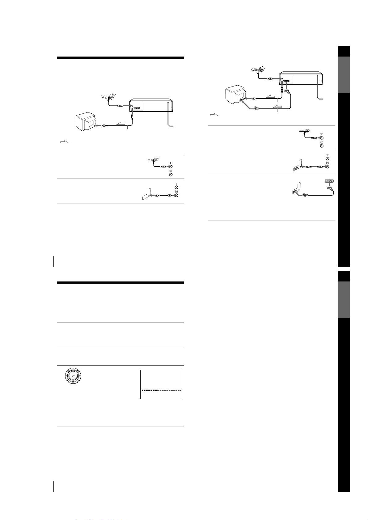
Step 3 : Connecting the VCR
If your TV has a Scart (EURO-AV) connector, see page 13.
If your TV does not have a Scart (EURO-AV) connector
Note
• When you connect the VCR a nd your TV only with an aerial cable, you have to
tune your TV to the VCR (see page 14).
1
Disconnect the aerial cable from
your TV and connect it to IN
FRONT ANT. on the rear panel of
the VCR.
2
Connect OUT TO TV of the VCR
and the aerial input of your TV
using the supplied aerial cable.
AERIAL IN
Aerial cable (supplied)
OUT TO TV
: Signal flow
IN FRONT ANT.
Getting Started
13
Connecting the VCR
If your TV has a Scart (EURO-AV) connector
1
Disconnect the aerial cable from
your TV and connect it to IN
FRONT ANT. on the rear pan el of
the VCR.
2
Connect OUT TO TV of the VCR
and the aerial input of your TV
using the supplied aerial cable.
3
Connect AV1 (EURO AV) on the
VCR and the Scart (EURO-AV)
connector on the TV with the
optional Scart cable.
This connection improves picture
and sound quality. Whenever you
want to watch the VCR picture,
press t TV/VIDEO to display
the VCR indicator in the display
window.
AV1
(EURO AV)
AERIAL IN
Scart (EURO-AV)
Aerial cable (supplied)
OUT TO TV
: Signal flow
Scart cable (not supplied)
IN FRONT ANT.
Getting Started
15
Setting up the VCR with the Auto Set Up function
Tip
• If you want to change th e language for the on-screen display, see page 16.
Notes
• Whenever you operate the Auto Set Up function, some of the settings (VIDEO
Plus+, timer, etc.) will be reset. If this happens, you have to set them again.
• After using the Auto Set Up function, the message for the Auto Set Up does not
appear automatically when you connect th e mains lead again. If you want to use
the Auto Set Up function again, press MENU, then press M/m/</, to highlight
INSTALLATION and press OK. Press M/m to highlight AUTO SET UP, then
repeat the procedure from step 3.
14
Setting up the VCR with the Auto Set Up function
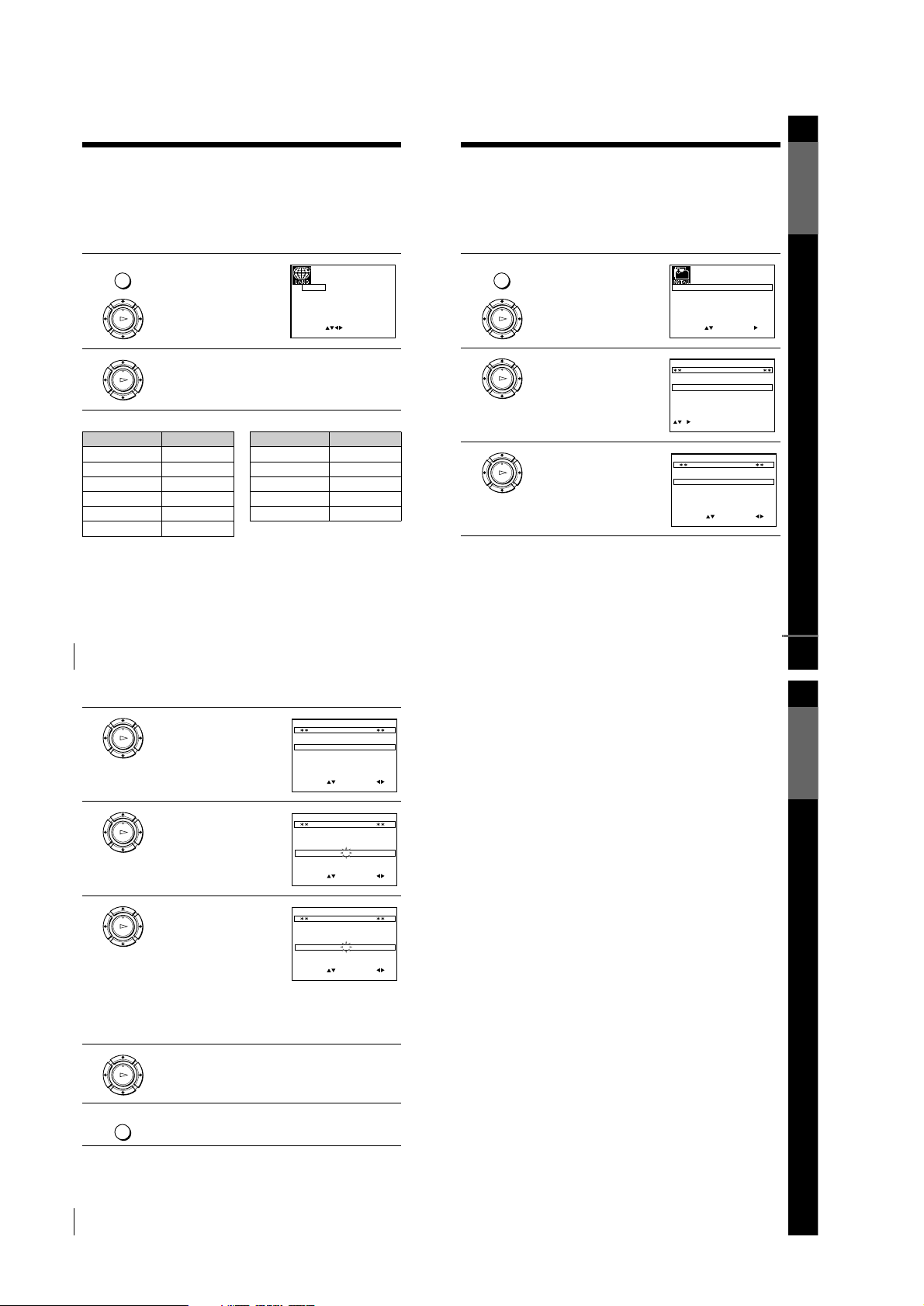
Step 4 : Setting up the VCR with the Auto
Set Up function
Before using the VCR for the first time, set up the VCR using the Auto Set Up
function. With this function, you can set the TV channels, guide channels for the
VIDEO Plus+ system, and VCR clock automatically.
To cancel the Auto Set Up function
Press MENU.
To change the RF channel
If the picture does not appear clearly on the TV, change the RF channel on
the VCR and TV. Select INSTALLATION from the menu, then press M/m
to highlight VCR OUTPUT CH and press ,. Select the RF channel by
pressing the M/m buttons. Then, tune the TV to the new RF channel so that
a clear picture appears.
1
Turn on your TV and set it to the video channel.
If your TV does not have a Scart (EURO-AV) connector, tune the
TV to channel 21 (the initial RF channel for this VCR). Refer to
your TV manual for TV tuning instructions. If the picture does not
appear clearly, see “To change the RF channel.”
2
Connect the mains lead to the mains.
The VCR automatically turns on, and the message for the Auto Set
Up function appears.
3
Press OK.
The VCR starts searching for all of
the receivable channels and presets
them in the appropriate order for
your local area.
If you want to change the order of
the channels or disable unwanted
programme positions, see
“Changing/disabling programme
positions” on page 20.
After the search or download is complete, the current time appears
for any stations that transmit a time signal. If the time does not
appear, set the clock manually. See “Setting the clock” on page 25.
OK
PLAY
MENU:
PLEASE WAIT
AUTO SET UP
40%
EXIT
1-4
16
Selecting a language
Selecting a language
If you prefer an on-screen language other than English, use the on-screen display to
select another language.
Before you start…
• Turn on the VCR and the TV.
• Set the TV to the video channel.
• Refer to “Index to parts and controls” for button locations.
The abbreviations of the languages are as follows:
1
Press MENU, then press M/m/</
, to highlight LANGUAGE SET
and press OK.
2
Press M/m/</, to highlight the abbreviation of the desired
language from the table below, then press OK.
MENU
OK
PLAY
EXIT MENU:OK:SET
SELECT :
GB
IT
ES
DK
DE
NL
PT
FI
FR
GR
SE
OK
PLAY
Abbreviation Language
GB English
DE German
FR French
IT Italian
NL Dutch
GR Greek
ES Spanish
PT Portuguese
SE Swedish
DK Danish
FI Finnish
Abbreviation Language
Getting Started
17
Presetting channels
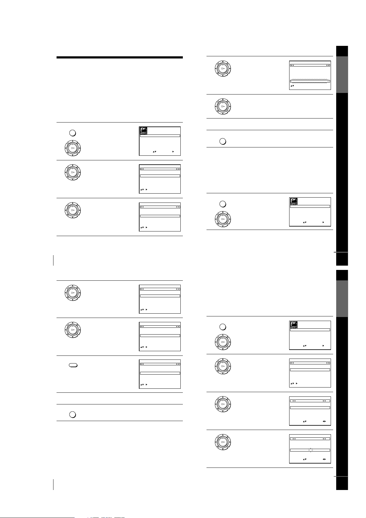
Presetting channels
If some channels could not be preset using the Auto Set Up function, you can preset
them manually.
Before you start…
• Turn on the VCR and the TV.
• Set the TV to the video channel.
• Refer to “Index to parts and controls” for button locations.
1
Press MENU, then press M/m/</
, to highlight INSTALLATION
and press OK.
2
Press M/m to highlight MANUAL
SET UP, then press ,.
3
Press M/m to highlight the row
which you want to preset, then press
,.
To displa y oth er pages for
programme positions 6 to 80, press
M/m repeatedly.
MENU
OK
PLAY
EXIT
SET
MENU:
:
OK:END
SELECT
AUTO SET UP
MANUAL SET UP
CH21:VCR OUTPUT CH
:
OK
PLAY
EXIT MENU:CLEAR:DELETE
SWAPPING OK
TV STATION TABLE
:
5
4
3
2
1
0
0
0
0
3
3
2
2
2
0
9
7
I
C
L
A
J
D
M
A
K
E
N
B
–
–
–
–
OFF
OFF
OFF
OFF
PR CH NAME DEC
OK
PLAY
MENU:OK:END
SELECT
MANUAL TUNING
PR : 5
CH : –––
MFT : –
NAME : ––––
:
SET :
EXIT
continued
Getting Started
19
Presetting channels
If the picture is not clear
If the picture is not clear, you may use the Manual Fine Tuning (MFT)
function. After step 4, press M/m to select MFT. Press </, to get a clear
picture, then press MENU to exit the menu.
Note
• When adjusting MFT, the menu may become difficult to read due to interference
from the picture being received.
18
Presetting channels
4
Press </, repeatedly until the
channel you want is displayed .
5
Press M/m to highlight NAME, then
press ,.
6
Enter the station name.
1 Press M/m to select a character.
Each time you press M, the character
changes as shown below.
A t B t … t Z t 0 t 1 t
… t 9 t A
2 Press , to set the next
character.
The next space is flashed.
To correct a character, press </, until the character you want to
correct is flashed, then reset it.
You can set up to 4 characters for the station name.
7
Press OK to confirm the station name.
8
Press MENU to exit the menu.
OK
PLAY
MENU:OK:END
SELECT
MANUAL TUNING
PR : 5
CH : 033
MFT : –
NAME : ––––
:
SET :
EXIT
OK
PLAY
MENU:OK:END
SELECT
MANUAL TUNING
PR : 5
CH : 033
MFT : –
NAME : ––––
:
SET :
EXIT
OK
PLAY
MENU:OK:END
SELECT
MANUAL TUNING
PR : 5
CH : 033
MFT : –
NAME : O–––
:
SET :
EXIT
OK
PLAY
MENU
1-5
20
Changing/disabling programme positions
Changing/disabling programme positions
After setting the channels, you can change the programme positions as you like. If
any programme positions are unused or contain unwanted channels, you can disable
them.
You can also change th e station names. If the station names are n ot displayed, you can
enter them manually.
Changing programme positions
Before you start…
• Turn on the VCR and the TV.
• Set the TV to the video channel.
• Refer to “Index to parts and controls” for button locations.
1
Press MENU, then press M/m/</
, to highlight INSTALLATION
and press OK.
2
Press M/m to highlight MANUAL
SET UP, then press ,.
3
Press M/m to highlight the row
which you want to change the
programme position.
To display other pages for
programme positions 6 to 80, press
M/m repeatedly.
MENU
OK
PLAY
SET
MENU:
:
OK:END
SELECT
AUTO SET UP
MANUAL SET UP
VCR OUTPUT CH
:
:
EXIT
CH21
OK
PLAY
CH
MENU:CLEAR:DELETE
SWAPPING OK
TV STATION TABLE
:
5
4
3
2
1
0
0
0
0
3
3
2
2
2
0
9
7
I
C
L
A
J
D
M
A
K
E
N
B
–
–
–
–
OFF
OFF
OFF
OFF
PR NAME DEC
EXIT
OK
PLAY
CH
MENU:CLEAR:DELETE
SWAPPING OK
TV STATION TABLE
:
5
4
3
2
1
0
0
0
0
3
3
2
2
2
0
9
7
I
C
L
A
J
D
M
A
K
E
N
B
–
–
–
–
OFF
OFF
OFF
OFF
PR NAME DEC
EXIT
Getting Started
21
Changing/disabling programme positions
Disabling unwanted programme positions
After presetting channels, you can disable unused programme positions. The disabled
positions will be skipped later when you press the PROG +/– buttons.
Before you start…
• Turn on the VCR and the TV.
• Set the TV to the video channel.
• Refer to “Index to parts and controls” for button locations.
4
Press OK, then press M/m to move
to the desired programme position.
5
Press OK to confirm the setting.
6
To change the p rog ramme p osi tion o f ano ther s t ation, repeat s teps 3
through 5.
7
Press MENU to exit the menu.
1
Press MENU, then press M/m/</
, to highlight INSTALLATION,
and press OK.
OK
PLAY
CH
MENU:
SWAPPING OK
TV STATION TABLE
:
5
4
3
2
1
0
0
0
0
2
3
3
2
9
2
0
7
L
I
C
A
M
J
D
A
N
K
E
B
–
–
–
–
OFF
OFF
OFF
OFF
PR NAME DEC
EXIT
OK
PLAY
MENU
MENU
OK
PLAY
SET
MENU:
:
OK:END
SELECT
AUTO SET UP
MANUAL SET UP
VCR OUTPUT CH
:
:
EXIT
CH21
continued
Getting Started
23
Changing/disabling programme positions
Changing the station names
You can chan ge or enter the station n ames (u p to 4 characters). T he VCR must recei v e
channel information for station names to appear automatically.
Before you start…
• Turn on the VCR and the TV.
• Set the TV to the video channel.
• Refer to “Index to parts and controls” for button locations.
1
Press MENU, then press M/m/</
, to highlight INSTALLATION
and press OK.
2
Press M/m to highlight MANUAL
SET UP, then press ,.
3
Press M/m to highlight the row
which you want to change or enter
the station name, then press ,.
To display other pages for
programme positions 6 to 80, press
M/m repeatedly.
4
Press M/m to highlight NAME, then
press ,.
MENU
OK
PLAY
SET
MENU:
:
OK:END
SELECT
AUTO SET UP
MANUAL SET UP
VCR OUTPUT CH
:
:
EXIT
CH21
OK
PLAY
CH
MENU:CLEAR:DELETE
SWAPPING OK
TV STATION TABLE
:
5
4
3
2
1
0
0
0
0
0
3
3
3
2
2
3
2
0
9
7
–
I
C
L
A
–
J
D
M
A
–
K
E
N
B
–
–
–
–
–
OFF
OFF
OFF
OFF
OFF
PR NAME DEC
EXIT
OK
PLAY
MENU:OK:END
SELECT
MANUAL TUNING
PR : 5
CH : 033
MFT : –
NAME : ––––
:
SET :
EXIT
OK
PLAY
MENU:OK:END
SELECT
MANUAL TUNING
PR : 5
CH : 033
MFT : –
NAME : ––––
:
SET :
EXIT
continued
22
Changing/disabling programme positions
Note
• Be sure to select the programme position you want to disable correctly. If you
disable a programme position by mistake, you need to reset that channel manually.
2
Press M/m to highlight MANUAL
SET UP, then press ,.
3
Press M/m to highlight the row
which you want to disable.
To display other pages for
programme positions 6 to 80, press
M/m repeatedly.
4
Press CLEAR.
The selected row will be cleared as
shown on the right.
5
Repeat steps 3 and 4 for any other programme positions you want to
disable.
6
Press MENU to exit the menu.
OK
PLAY
CH
EXIT MENU:CLEAR:DELETE
SWAPPING OK
TV STATION TABLE
:
5
4
3
2
1
0
0
0
0
3
3
2
2
2
0
9
7
I
C
L
A
J
D
M
A
K
E
N
B
–
–
–
–
OFF
OFF
OFF
OFF
PR NAME DEC
OK
PLAY
MENU:CLEAR:DELETE
SWAPPING OK
TV STATION TABLE
:
5
4
3
2
1
0
0
0
0
3
3
2
2
2
0
9
7
I
C
L
A
J
D
M
A
K
E
N
B
–
–
–
–
OFF
OFF
OFF
OFF
PR CH NAME DEC
EXIT
CLEAR
CH
MENU:CLEAR:DELETE
SWAPPING OK
TV STATION TABLE
:
5
4
3
2
1
0
0
0
3
3
2
2
0
7
I
C
A
J
D
A
K
E
B
–
–
–
OFF
OFF
OFF
PR NAME DEC
EXIT
MENU
1-6
24
Changing/disabling programme positions
5
Enter the station name.
1 Press M/m to select a character.
Each time you press M, the character
changes as shown below.
A t B t … t Z t 0 t 1 t
… t 9 t A
2 Press , to set the next
character.
The next space is flashed.
To correct a character, press </, until the character you want to
correct is flashed, then reset it.
You can set up to 4 characters for the station name.
6
Press OK to confirm the new name.
7
Press MENU to exit the menu.
OK
PLAY
EXIT MENU:OK:END
SELECT
MANUAL TUNING
PR : 5
CH : 033
MFT : –
NAME : O–––
:
SET :
OK
PLAY
MENU
Getting Started
25
Setting the clock
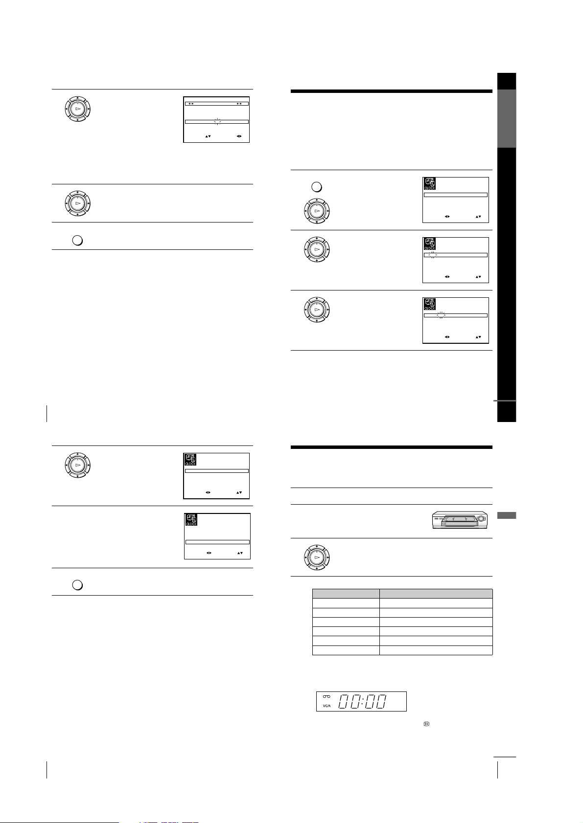
Setting the clock
You must set the time and date on the VCR to use the timer features properly.
The Auto Clock Set function works only if a station in your area is broadcasting a
time signal.
Before you start
…
• Turn on the VCR and the TV.
• Set the TV to the video channel.
• Refer to “Index to parts and controls” for button locations.
1
Press MENU, then press M/m/</
, to highlight CLOCK SET and
press OK.
2
Press M/m to set the hour.
3
Press , to select the minutes and
set the minutes by pressing M/m.
MENU
OK
PLAY
SET
MENU:
:
OK:END
SELECT
1 2 0 1 JAN/0:20
MON
01/
AUTO CLOCK ON:
:
EXIT
OK
PLAY
SET
MENU:
:
OK:END
SELECT
1 8 0 1 JAN/0:20
MON
01/
AUTO CLOCK ON:
:
EXIT
OK
PLAY
SET
MENU:
:
OK:END
SELECT
1 8 3 1 JAN/0:20
MON
01/
AUTO CLOCK ON:
:
EXIT
continued
27
Playing a tape
Basic Operations
Basic Operations
Playing a tape
Before you start...
• Refer to “Index to parts and controls” for button locations.
Additional tasks
To use the time counter
Press CLEAR at the point on the tape that you want to find later. The
counter in the display window resets to “00:00.” Search for the point
afterwards by referring to the counter.
To display the counter on the TV screen, press DISPLAY.
1
Turn on your TV and set it to the video channel.
2
Insert a tape.
The VCR turns on and starts playing
automatically if you insert a tape with
its safety tab removed.
3
Press H PLAY.
When the tape reaches the end, it will rewind automatically.
To Press
Stop play x STOP
Pause play X PAUSE
Resume play after pause X PAUSE or H PLAY
Fast-forward the tape M FF during stop
Rewind the tape m REW during stop
Eject the tape Z EJECT
OK
PLAY
continued
26
Setting the clock
Tips
• If you set AUTO CLOCK to ON, the Auto Clock Set function is activated
whenever the VCR is turned off. The time is adjusted automatically by making
reference to the time signal from the station.
• To change the digits while setting , press < to return to the ite m to be cha nged, an d
select the digits by pressing M/m.
4
Set the day, month, and year in
sequence by pressing , to select
the item to be set, and press M/m to
select the digits, then press ,.
The day of the week is set
automatically.
5
Press M/m to select ON for the
setting the Auto Clock Set function.
The VCR automatically set the
clock by the channel between PR01
to PR05 broadcasting the time
signal.
If you do not need the Auto Clock
Set function, select OFF.
6
Press MENU to exit the menu.
OK
PLAY
SET
MENU:
:
OK:END
SELECT
18 3 82 SEP/0:20
FRI
01/
AUTO CLOCK ON:
:
EXIT
SET
MENU:
:
OK:END
SELECT
18 3 82 SEP/0:20
FRI
01/
AUTO CLOCK ON:
:
EXIT
MENU
1-7
28
Playing a tape
Notes
• The counter resets to “00:00” whenever a tape is reinserted.
• The counter stops counting when it comes to a portion with no recording.
• Depending on your TV, the following m ay occur while playing an NTSC-recorde d
tape:
–The picture becomes black and white.
–The picture shakes.
–No picture appears on the TV screen.
–Black streaks appear horizontally on the TV screen.
–The colour density increases or decreases.
• While setting the menu on the TV screen, buttons for playback on the remote
commander do not function.
29
Recording TV programmes
Basic Operations
Recording TV programmes
Before you start...
• Refer to “Index to parts and controls” for button locations.
To s to p r e co rd ing
Press x STOP.
1
Turn on your TV and set it to the video channel.
2
Insert a tape with its safety tab in place.
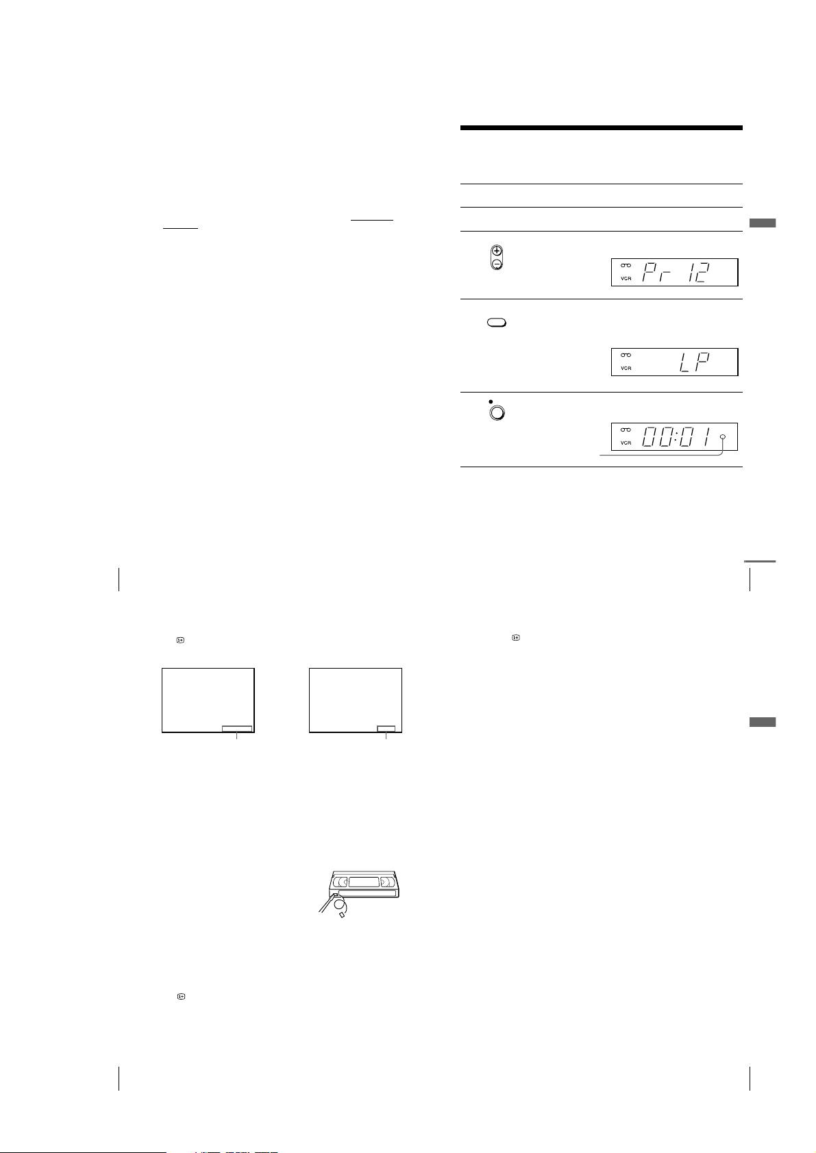
3
Press PROG +/– to select the programme position you want to
record.
4
Press SP/LP to select the tape speed, SP or LP.
LP (Long Play) provides recording time twice as long as SP.
However, SP (Standard Play) produces better picture and audio
quality.
5
Press z REC to start recording.
The recording indicator lights up red in the display window.
• PROG
SP / LP
REC
Recording indicator
continued
31
Recording TV programmes
Basic Operations
Notes
• The DISPLAY information does not appear during pause mode and the various
speeds of playback mode. However, it will appear during normal playback.
• If a tape has portions recorded in both PAL and NTSC systems, the time counter
reading will not be correct. This discrepancy is due to the difference between the
counting cycles of the two video systems.
• When you insert a non-standa rd commercially available tape, the remaining time
may not be correct.
• The remaining time is intended for rough measurement only.
• About 30 seconds after the tape begins playback, the tape remaining time will be
displayed.
30
Recording TV programmes
To check the remaining time
Press DISPLAY. With the display on, press COUNTER/REMAIN to
check the remaining time. Each time you press COUNTER/REMAIN, the
time counter and the remaining time appear alternately.
In order to get an accurate remaining time indication, be sure TAPE
SELECT in the USER SET menu is set according to the tape type you use
(see page 44).
To watch another TV programme while recording
To save a recording
To prevent accidental erasure, break off the
safety tab as illustrated. To record on the
same tape again, cover the tab hole with
adhesive tape.
Tips
• To select a programme positio n, you can use the prog ramme numb er butt ons on the
remote commander. For two-digit numbers, press the - (ten’s digit) button
followed by the programme number buttons.
• If you connect additional equipment to an input connecto r , yo u can selec t the in put
signal using the INPUT SELECT or PROG +/– buttons.
• The DISPLAY information appears on the TV screen indicating information
about the tape, but the information won’t be recorded on the tape.
• If you don’t want to watch TV while recording, you can turn off the TV.
• The remaining tape length may not be indicated accurately for short tapes such as
E-20 or E-30, or tapes recorded in the LP mode.
1
Press t TV/VIDEO to turn off the VCR indicator in the display
window.
2
Select another programme position on the TV.
461:
REMAIN
22000::
SP
Remaining timeTime counter
Safety tab
1-8
32
Recording TV programmes using the VIDEO Plus+ system
Recording TV programmes using the
VIDEO Plus+ system
The VIDEO Plus+ system is the feature that simplifies programming the VCR to
make timer recordings. Just enter the PlusCode number listed in the TV programme
guide. The date, times, and programme position of that programme are set
automatically. You can preset a total of six programmes, including settings made with
other timer methods.
Before you start
…
• Check that the VCR clock is set to the correct time and date.
• Insert a tape with its safety tab in place. Make sure the tape is lon g er than the t otal re cor din g
time.
• Turn on your TV and set it to the video channel.
• Set TIMER METHOD to VIDEOPLUS or VARIABLE in the USER SET menu (see page
45).
• Refer to “Index to parts and controls” for button locations.
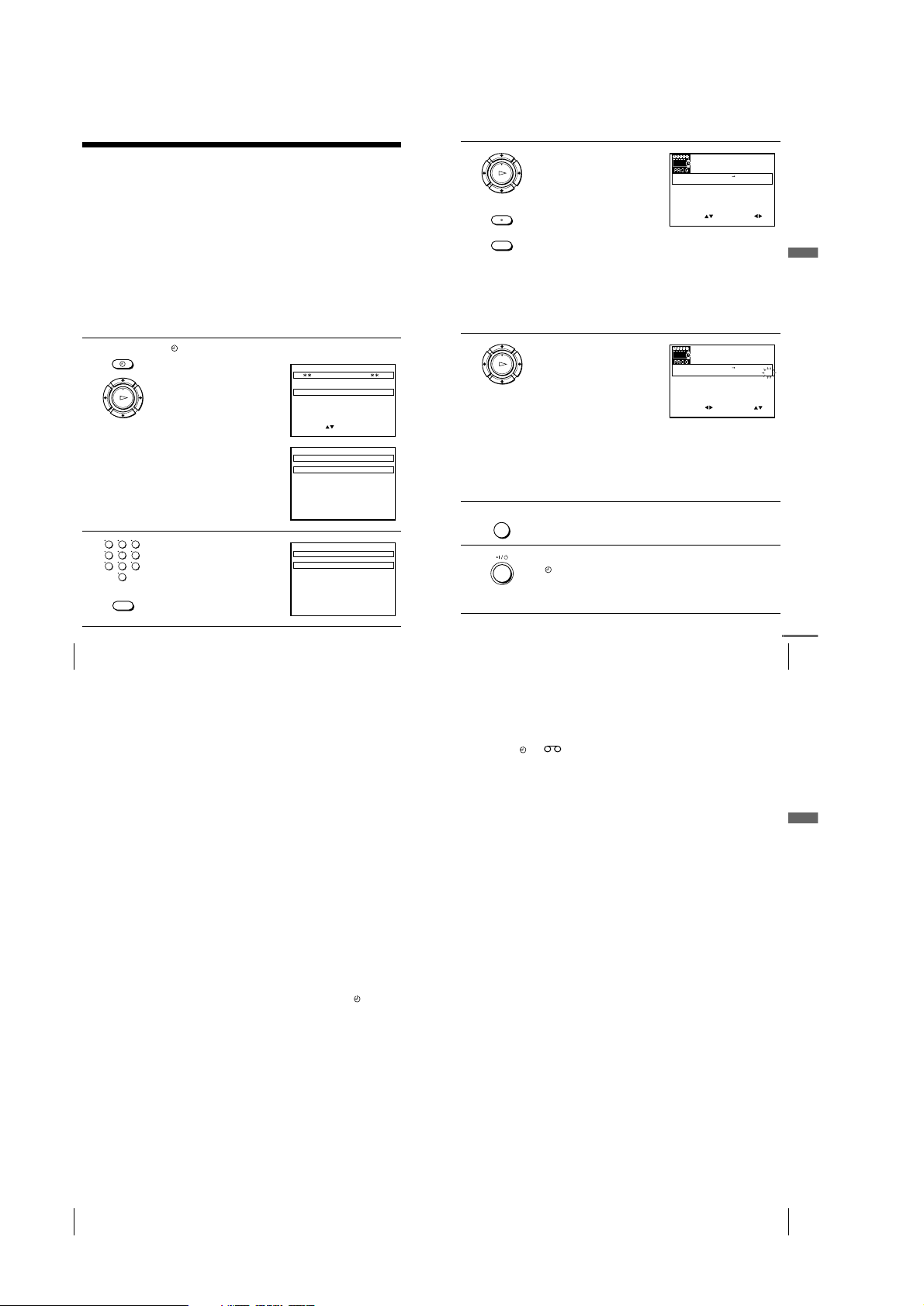
1
Press TIMER.
• When you set TIMER METHOD
to VARIABLE:
The TIMER METHOD menu
appears on the TV screen. Press
M/m to select VIDEOPLUS, then
press OK.
• When you set TIMER METHOD
to VIDEOPLUS:
The VIDEOPLUS menu appears
on the TV screen.
2
Press the programme number
buttons to enter the PlusCode
number.
If you make a mistake, press
CLEAR and re-enter the correct
number.
TIMER
OK
PLAY
MENU:OK:SET
SELECT :
EXIT
TIMER METHOD
STANDARD
VIDEOPLUS
MENU:OK:SET
CODE 0 – 9:
VIDEOPLUS
CODE –––––––––
EXIT
123
456
789
0
CLEAR
MENU:OK:SET
CODE 0 – 9
1234–––––
:
VIDEOPLUS
CODE
EXIT
33
Recording TV programmes using the VIDEO Plus+ system
Basic Operations
3
Press OK.
The programme position, date, start
and stop times, tape speed, and
VPS/PDC setting appear on the TV
screen.
• If “– –” appears in the “PR”
(programme) column (this may
happen for local broadcasts), you
have to set the appropriate
programme position manually.
Press M/m to select the desired programme position.
To record from another source connected to the input connector,
press INPUT SELECT to display the connected line in the “PR”
position.
You will only have to do this operation once for the referred
channel. The VCR will then store your setting.
If the information is incorrect, press CLEAR to cancel the setting.
4
If you want to change the date, tape
speed, and the VPS/PDC setting:
1 Press </, to select the item
you want to change.
2 Press M/m to reset it.
• To record the same programme
every day or the same day every
week, see “Daily/weekly
recording” on page 34.
• To use the VPS/PDC function, set
V/P to ON. For details about the VPS/PDC function, see “Timer
recording with VPS/PDC signals” on page 34.
• To use the Auto Tape Speed function, press m to display “AUTO”
in the blank positions next to the “V/P” row. For details, see “To
use the Auto Tape Speed function” on page 34.
5
Press MENU to exit the menu.
6
Press ?/1 to turn off the VCR.
The indicator appears in the display window and the VCR stands
by for recording.
To record from another source, leave the connected equipment
switched on.
CLEAR
OK
PLAY
INPUT
SELECT
EXIT
SET
MENU:
:
OK:END
SELECT
–– –––– –– –– – ––– ––::
PR DAY START STOP
V/P
FRISEP82/ 18:30
35SA2919002 00 –
LP
0::
–– –––– –– –– – ––– ––::
–– –––– –– –– – ––– ––::
–– –––– –– –– – ––– ––::
–– –––– –– –– – ––– ––::
:
OK
PLAY
EXIT
SET
MENU:
:
OK:END
SELECT
–– –––– –– –– – ––– ––::
PR DAY START STOP
V/P
ON
FRISEP82/ 18:30
35SA2919002 00
LP
0::
–– –––– –– –– – ––– ––::
–– –––– –– –– – ––– ––::
–– –––– –– –– – ––– ––::
–– –––– –– –– – ––– ––::
:
MENU
continued
35
Recording TV programmes using the VIDEO Plus+ system
Basic Operations
Notes
• If the VPS/PDC signal is too weak or the broadcasting station failed to transmit
VPS/PDC signals, the VCR will start recording at the set time without using the
VPS/PDC function.
• The and indicators flash in the display window when you press ?/1 with
no tape inserted.
• When you set TIMER METHOD to STANDARD in the USER SET menu, the
VIDEOPLUS menu does not appear on the TV screen. Select VIDEOPLUS or
VARIABLE.
34
Recording TV programmes using the VIDEO Plus+ system
To stop recording
To stop the VCR while recording, press x STOP.
Daily/weekly recording
In step 4 above, press m to select the recording pattern. E ach time you p ress
m, the indication changes as shown below. Press M to change the indication
in reverse order.
today t DLY (Monday to Sunday) t W-SAT (every Saturday) ..... t
W-SUN (every Sunday) t 1 month later t (dates count down) t today
Timer recording with VPS/PDC signals
Some broadcast systems transmit VPS (Video Programme System) or PDC
(Programme Delivery Control) signals with their TV programmes. These
signals ensure that your timer recordings are made regardless of broadcast
delays, early starts, or broadcast interruptions.
To use the VPS/PDC function, set V/P to ON in step 4 above. You can also
use the VPS/PDC function for a source connected to the input connector.
To use the Auto Tape Speed function
In step 4 above, press m to select AUTO. When you are recording a
programme in the SP mode and the remaining tape length becomes shorter
than the recording time, the recording tape speed is automatically changed to
the LP mode. Note that some noise will appear on the picture when the tape
speed is changed. To operate this function correctly, the “TAPE SELECT”
setting in the USER SET menu must be accurate. (page 44)
To use the VCR after setting the timer
To use the VCR before a recording begins, just press ?/1. The indicator
turns off and the VCR switches on. Remember to press ?/1 to reset the VCR
to recording standby after using the VCR.
You can also do the following tasks while the VCR is recording:
• Reset the counter (page 27).
• Display tape information on the TV screen (page 30).
• Check the timer settings (page 41).
• Watch another TV programme (page 30).
Tips
• You can set the extended time for the VIDEO Plus+ setting b y 10, 20 , 30, or 60
minutes. Set VIDEOPLUS+ EXTEND in the EASY OPERATION menu to the
desired extended time (page 45).
• To check, change, or cancel the programme setting, see “Checking/changing/
cancelling timer settings” (page 41).
• To set the tape speed, you can also use the SP/LP button.
 Loading...