

Sony SLV-N81, SLV-N71 Owner’s Manual
S Ol i,rlt,; 300 51,1(1
Video Cassette
Recorder
Operating Instructions
If you have any questions about this product, you may call: Sony
Customer Information Services Center 1_800-222-SONY (7669) or
write to: Sony Customer Information Services Center 6900-29
Daniels Parkway, PMB 330, Fort Myers, FL 33912
Declaration of Conformity
Trade Name: SON Y
Model No.: SLV_N81/N71
Responsible Party: Sony Electronics Inc.
Address: 1 Sony Drive, Park Ridge, NJ_07656 USA
])lephone No.: 201 _930-6972
This device complies with Part 15 of the FCC Rides. Operation is subject to
the following two conditions: (1) This device may not cause hal_aful
interference, and (2) this device must accept any interference received,
including interference that may cause undesired operation.
© 2001 Sony Corporation
WARNING
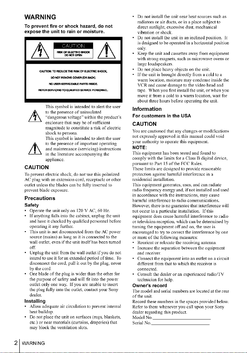
To prevent fire or shock hazard, do not
expose the unit to rain or moisture.
CAU13CN: TO F_DUCE _E FIISK OF ELECqRIC 8HO_
DO NOT R_4OVE COVt_ (OR BA_.
NO L,6ER_E P&]GE._BLE pART_ INVADE.
P_=_q SBRVIONG TO QLIALIFIED ,_RV1GE pERSONNB--
Tiffs symbol is intended to alert the user
"dangerous voltage" within tlle product's
//_ to the presence of uninsulated
enclosure that may be of sufficient
magnitude to constitute a risk of electric
shock to persons
This symbol is intended to alert the user
and maintenance (selwicing) instructions
//_ to the presence of imporiant operating
in the literature accompanying the
appliance.
CAUTION
1"o prevent electric shock, do not use this polarized
AC plug with an extension cord, receptacle or other
outlet unless the blades can be fully inserted to
prevent blade exposure
Precautions
Safety
• (_erate the unit only on 120 V AC, 60 Hz.
• I f anytldng falls into the cabinet, unplug lhe unit
and have it checked by qualified personnel before
operating it any further.
• This unit is not disconnected from the AC power
source (mains) as long as it is connected to the
wall outlet, even if the mtit itself has been turned
off.
• Unplug tbe unit from tbe wall outlet if you do not
intend to use it for an extended period of time 1o
disconnect the cord, pull it out by file plug, never
by the cord
• One blade of tlle plug is wider titan the otber for
the propose of safe*y and will fit into the power
outlet only one way. If you are unable to insert
the plug fully into fl_e outleL contact your Sony
dealer.
installing
• Allow adequate air circulation to prevent internal
heat buildup
• Do not place the unit on surfaces (rags, blankets,
etc) or near materials (curtains, draperies) that
may block the ventilation slots
• Do not install file unit near heat sources such as
radiators or air ducts, or in a place sul_ject to
direct sunlight, excessive dust, mechanical
vibration or shock.
• Do not ins*all the unit in an inclined position. It
is designed to be operated in a horizontal position
only
• Keep the unit and casse**es away fi'om equipment
with strong magnets, such as microwave ovens or
large loudspeakers
• Do not place heavy ot_jects on the unit
• If tbe unit is brougfit directly fi'om a cold to a
warm location, moisture may condense inside the
VCR and cause damage to the video head and
tape When you firs* install the unit, or when you
move it from a cold to a warm location, wait for
about tbree hours betbre operating the unit
Information
For customers in the USA
CAUTION
You are cautioned that any changes or modifications
not expressly approved in this manual could void
your authority to operate this equipment.
NOTE:
l'ltis equipment has been tested and found to
comply witll the lfinits for a Class B digital device,
pursumlt to Part 15 of tlle FCC Rules.
Fhese lfinits are designed to provide reasonable
protection against harmful interference in a
residential installation.
l'lds equipment generates, uses, and can radiate
radio frequency energy and, if not installed and used
in accordance with the instructions, may cause
harmful interference to radio communications.
However. there is no guarantee that interference will
not occurin a pm_dcular installation. If this
equipment does cause harmful interference to radio
or television reception, which can be determined by
turning the equipment offand on, the user is
encouraged to try to correct the interference by one
or more of the following measures:
• Reotient or reloca*e the receiving antenna
• Increase the separation between the equipment
and receiver
• Connect the equipment into an outlet on a circuit
different from that to which the receiver is
connected.
• Consult the dealer or an experienced radio/rV
technician Ibr help
Owner's record
l'he model and serial numbers are located at the rear
of the unit
Record these numbers in the spaces provided below.
Refer to filem whenever you call upon your Sony
dealer regarding this product
Model No.
Serial No.
2 WARNING
Important Safeguards
For your protection, please read these safety
instructions completely betbre operating the
appliance, and keep this manual lbr future reference
Carefully obsel_'e all warnings, precautions and
instructions on tbe appliance, or the one described in
the operating instructions and adhere to them.
Use
Power sources
This set sbould be operated only
from tile type of power source
indicated on the marking label If
you are not sure of the type of
electrical power supplied to your
home, consult your dealer or local power company.
For those sets designed to operate from battery
power, or other sources, rethr to the operating
instructions.
Grounding or Polarization
This set is equipped with a polarized ac power cord
plug (a plug having one blade wider than the other),
or with a tbree-wire grounding type plug (a plug
having a third pin for grounding) Follow the
instructions below:
For the set with a polarized ac power cord
plug:
This plug will fit into the power
outlet only one way. This is a
safety IEature. If you are unable
to insert the plug fully into the outlet, try reversing
the plug If the plug sbould still fail to fit, contact
your electrician to have a suitable outle_ installed.
Do not dethat the safety purpose of the polarized
plug by forcing it in.
For the set with a three-wire grounding
type ac plug:
This plug will only fit into a
grounding-type power outlet.
This is a safety f?3ture. If you are
unable to insert tile plug into the outlet, contact your
electrician to have a suitable outlet installed. Do not
dethat the safety purpose of the grounding plug
Overloading
Do 1"totoverload wall outlets,
extension cords or convenience I (_r_
receptacles beyond their capacity,
since tbis can result in fire or
electric sbock
Object and Liquid Entry
Never push ol_iec_s of any kind into
the set through openings as they
may touch dangerous vohage
points or sho_t out parts that could
result in a fire or electric shock.
Never spill liquid of any kind on the set.
Attachments
Do not use attachlrtents not
recommended by the manu_acture_; as
they may cause bazards.
Cleaning
Unplug tile set from the wall
outlet before cleaning or polisbing
it. Do not use liquid cleaners or
aerosol cleaners. Use a cloth
lightly dampened with water for
cleaning the exterior of the set
Installation
Water and Moisture
Do not use power-line operated sets f'_. Ik..--.
near water - for example, near a
bathtub, washbowl, kitchen sink, or
laundry tub, in a wet basement, or
near a swimming pool, eta
Power-Cord Protection
Route the power cord so tbat it is
not likely to be walked on or
pinched by items placed upon or
against tbem, paying particular attention to the
plugs, receptacles, and the point where the cord exits
from the appliance
Accessories
Do not place the set on an __._-_
unstable calf. stand, tripod,
bracket or table. The set may
fall, causing serious il_iury to a
child or an adult, and serious damage to tbe set. Use
only a cart stand tripod, bracket, or table
recommended by the manufacturer.
An appliance and cart
combination should be moved
witb care. Quick stops, excessive
force, and uneven surfaces may
cause the appliance and cmt
combination to overturn
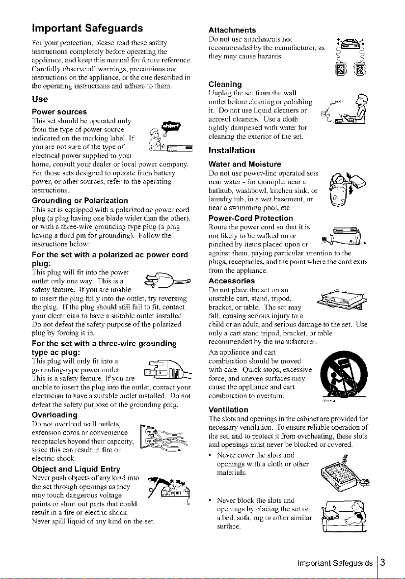
Ventilation
The slots and openings in the cabinet are provided for
necessary ventilation. To ensure reliable operation of
the set, and to protect it from overheating, tbese slots
and openings must never be blocked or covered
• Never cover the slo_s and
openings with a cloth or otber
materials.
• Never block tile slots and
openings by placing the set on
a bed, sofa, rug or other similar
surface.
Important Safeguards 3
• Never place the set in a
confined space, such as a
bookcase, or built-in cabinet,
unless proper ventilation is
provided.
• Do not place the set near or _ _9_1o_
over a radiator or heat register, ff _-:
or where it is exposed to direct
sunlight.
Antennas
Outdoor antenna grounding
If an outdoor antenna ot"cable system is installed,
follow the precautions below
An outdoor antenna system should not be located in
the vicinity of overhead power lines ot"other electric
light or power circuits, or where it can come in
contact with such power lines or circuits
WHEN INS'IALLING AN OU FDOOR ANTENNA
SYSTEM, EXTREME CARE SHOULD BE
IAKEN qo KEEP FROM CON IACYING SUCH
POWER LINES OR CIRCUITS AS CONqACT
WITH THEM IS ALMOST INVARIABLY FATAL
Besure the antenna system is grounded so as to provide
some wotecfion against voltage surges and built-up
static charges. Section 810 of the Nafiolmt Electrical
Codeprovides infonnafion with respect to propm-
gtounding of filemast and supporting structure,
grounding of filelead-in wire to an antenna discharge
unit, size of grounding conductol_, location of antenna-
disdlarge unit, connection to grounding electrodes, and
requirements for tbe grounding electrode
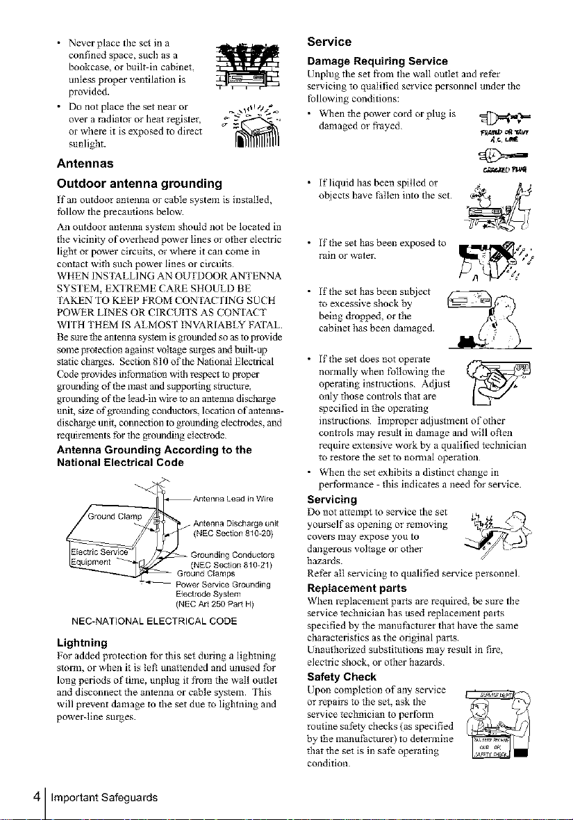
Antenna Grounding According to the
National Electrical Code
Antenna Discharge unit
(NEC Section 810-20)
_ kntenna Lead in Wire
= Power Service Grounding
NEC-NATIONAL ELECTRICAL CODE
Lightning
For added protection for this set dm'ing a lightning
storm, or when it is te_ unattended and unused for
long periods of time, unplug it from file wall outlet
and disconnect the antenna or cable system. This
will prevent damage to the set due to lightning and
powerqine surges.
Grounding Conductors
(NEC Section 810-21)
nd Clamps
Electrode System
(NEC Art 250 Part H)
Service
Damage Requiring Service
Unplug tile set from tile wall outlet and relhr
servicing to qualified service personnel under the
following conditions:
• v_qlentile power cord or plug is
damaged or flayed
• If liquid has been spilled or
ot_jects have fallen into the set
• If the set has been exposed to
rain or water.
• lithe sethas been subject
to excessive shock by
being dropped, orthe
cabinethas been damaged.
• If the set does not operate
normally when Ibllowing the {,_4_'_J
operating instructions Ac[iust
only those controls filat are
specified in the operating
instructions Improper adjustment o f other
conIrols may result in damage and will ol_en
require extensive work by a qualified tecbniciml
to restore the set to normal operation
• When tile set exhibits a distinct change in
performance - this indicates a need for service
Servicing
Do not attempt to service the set _,.
yourself as opening or removing
covers may expose you to _'_'-_ "-...__ _--'_
dangerous voltage or other
hazards.
Refer all servicing to qualified service personnel
Replacement parts
When replacement parts are required be sure the
service technician has used replacement pints
specified by file manul:acmrer that have file same
characteristics as the original parts.
Ufiauthorized substitutions may result in fire,
elec*ric shock, or ofiler hazards
Safety Check
Upon completion of any smMce
or repairs to tile set, ask the
service technician to perlbrm
routine safety checks (as specified
by the manufacturer) to determine
filat tile set is in safe operating
condition
FII411_' _l "14v,r
.ft. L/_
¢._taz D_va_
4 Important Safeguards
Table of contents
Getting Started
6 Step 1 : Unpacking
7 Step 2 : Setting up the remote commander
9 Step 3 : Hookups
27 Selecting alanguage
28 Setting the clock
35 Setting up the cable box control (SLV-N81 only)
41 Presetting channels
48 Setting up the VCR Plus+'?_ GOLD system (SLV-N81 only)
55 Setting up the VCR Plus+,?_ system (SLV-N71 only)
Basic Operations
59 Playing a tape
62 Recording TV programs
65 Recording TV programs using the
Dial Timer
70 Recording TV programs using the
VCR Plus+ or VCR Plus+ GOLD
system
73 Setting the timer manually
85 Searching for a selected point on the
tape
87 Locating a channel by Station ID
(SLV-N81 only)
88 Crea_ing a favorite channel list with
Station ID (SLV-N81 only)
90 Adjusting the picture
92 Changing menu options
94 Editing with another VCR
76 Locking the VCR (Child Lock)
Additional Information
Additional Operations
77 Playing/searching at various speeds
79 Setting the recording duration time
80 Checking/changing/canceling timer
settings
82 Recording s_ereo and bilingual
programs
96 General setup information
98 Troubleshooting
100 Specifications
101 Index to parts and comrols
106 Index
Back Cover
Quick reference _o using the VCR
84 Searching using the index function
VCR Plus+, (-;3, ALLSET and PlusCode are trademarks of Gemstar Development Corporation.
The VCR Plus_ system is manufactured under license fl'om Gemstar Development Coq_orafion.
Caution
Televisiot_ programs, films, video tapes and other materials may be copyrighted.
Unauthorized recording of such material may be contrary to the provisions of the copyright laws. Also, use
of this recorder with cable television transmission may require authorization fi'om the cable television
transmission and/or program owner.
Table of contents I 5
Getting Started
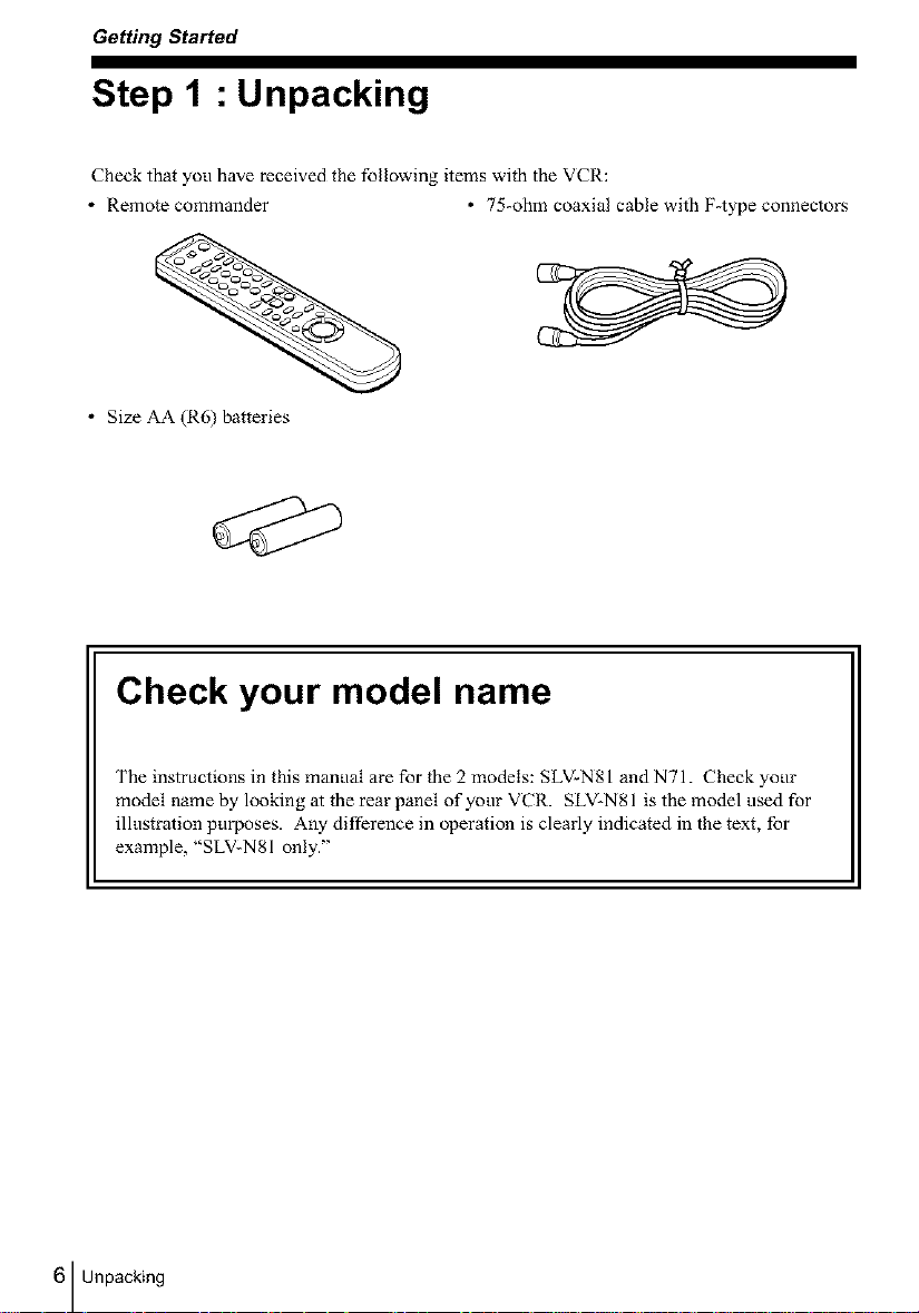
Step 1 : Unpacking
Check that you have received the following items wil-h the VCR:
• Remote commander * 75-ohm coaxial cable with F-type connectors
• Size AA (R6) batteries
Check your model name
The instructions in this manual are for the 2 models: SLV-N81 and N71. Check your
model _ame by looking at the rear panel of your VCR. SLV-N81 is the model used for
illustration purposes. Any difference in operation is clearly indicated in the text, for
example, "SLV-N81 only."
6 Unpacking
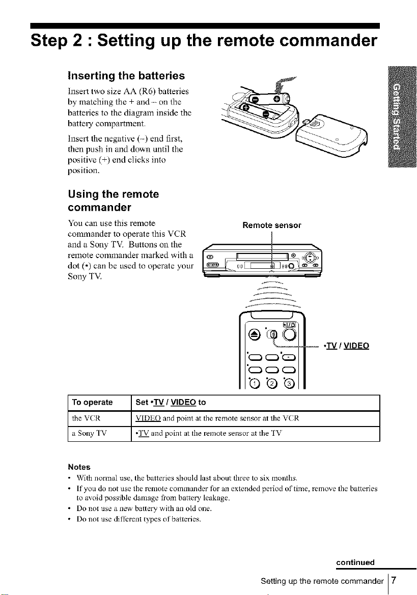
Step 2 : Setting up the remote commander
Inserting the batteries
Insert two size AA (R6) batteries
by matching the + and on the
batteries to the dia_am inside the
battery compartment.
Insert the negative () end first,
then push in and down until the
positive (+) end clicks into
position.
Using the remote
commander
Yon can use this remote
commander to operate this VCR
and a Sony TV. Buttons on the
remote commander marked with a
dot (,) can be used to operate yonr
Sony TV.
Remote sensor
@ ©
,-- .TV / VIDEO
5 o_ca
To operate
the V('R
a Sony TV
Notes
• With normal nse, the ba*teries should last about three to six monlhs.
• If you do not use the remote comnlander for an extended period of time, remove the batteries
to avoid possible damage from battery leakage.
• Do not use a new batte_T with an old one.
• Do not use different types of batteries.
Set ,'IV / VIDEO to
VIDE() and point at the remote sensor at the VCR
*'1V and point at the remote sensor at the IV
continued
Setting up the remote commander I 7
I
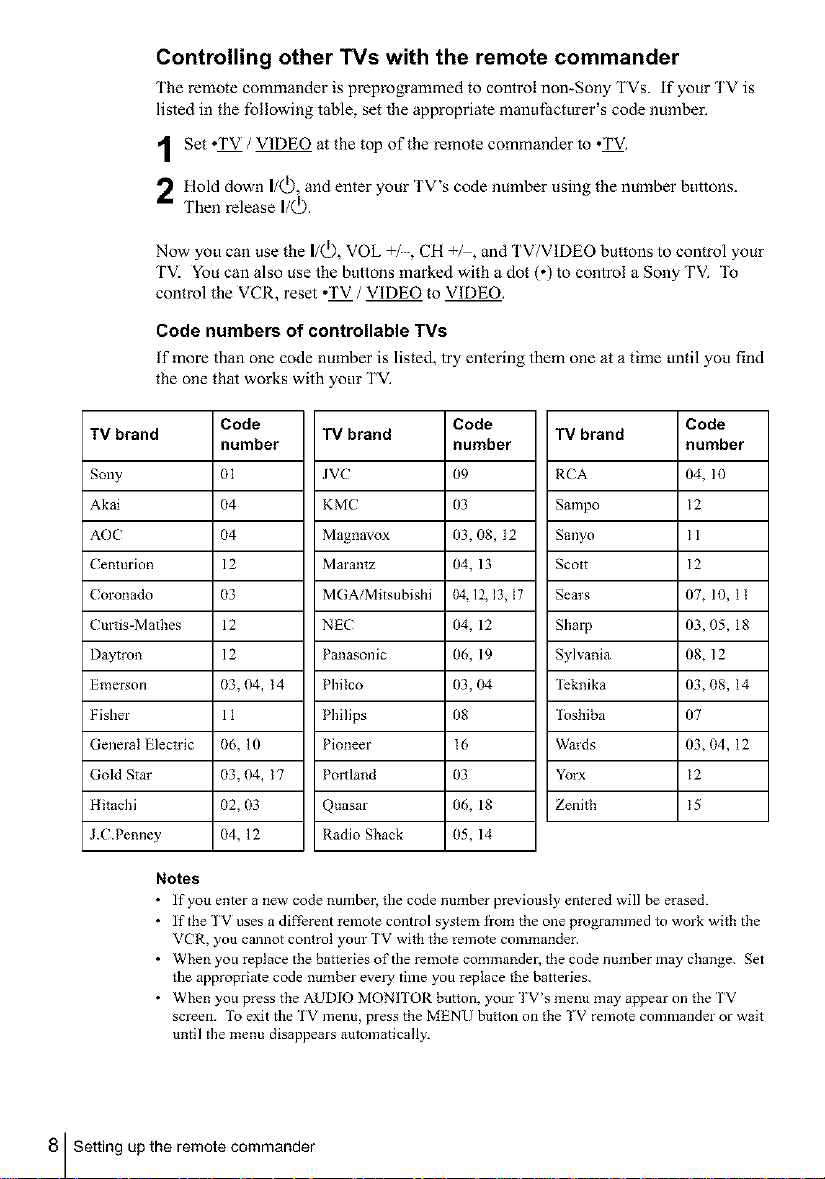
Controlling other TVs with the remote commander
The remote commander is preprogrammed to control non-Sony TVs. if your TV is
• . . _ •
hsted m the following table, set the appropriate mant f_actt rer s code number.
1 Set oTV / VIDEO at the top of the remote commander to oTV.
Hold down I/Q), and enter your TV's code number using the number buttons.
Then release I/Q).
Now you can use the I/Q), VOL +/, CH +/, and TV/VIDEO buttons to control your
TVI You can also use the buttons marked with a dot (o) to control a Sony TVI _1_
control the VCR, reset oTV / VIDEO to VIDEO.
Code numbers of controllable TVs
If more than one code number is listed, try entering them one at a time until you find
the one that works with your TVI
TV brand TV brand TV brand
Sony 01 JV(" 09 RCA 04, 10
Akai 04 KMC 03 Sampo 12
AOC 04 Magnavox 03, 08, 12 Sanyo I 1
Centurion 12 Marantz 04, 13 Scott 12
Coronado 03 MGAiMitsubishi 04.12, 13, I7 Sem's 07, 10, 1 t
Cmtis-Matbes 12 NEC 04, 12 Sharp 03, 05, 18
Daytron 12 Panasonic 06, 19 Sylvania 08, 12
Emerson 03, 04, t 4 Philco 03, 04 leknika 03, 08, 14
Fisher 11 Philips 08 1oshiba 07
General Elech'ic 06, 10 Pioneer I6 Wards 03, 04, 12
Gold Star 03, 04, t 7 Poltland 03 Yorx 12
Hitachi 02, 03 Quasar 06, 18 Zenith 15
J.C.Pemley 04, 12 Radio Shack 05, 14
Notes
• If you enter a new code number, the code nmnber previously entered will be erased.
• If the TV uses a differet_t remote control system from tbe one programmed to work with the
• When you replace the batteries of the remote commander, the code number may cba_ge. Set
• Wheny°upresstbeAUDIOMONITORbutt°n'y°url'V'smenumayappear°ntheTV
Code Code Code
number number number
VCR, you cannot control your TV with the remote commander.
the appropriate code number every time you replace the batteries.
screen. To exit the 1V menu, press the MENU button on the TV remote commander or wait
until the menu disappears automatically.
8 Setting up the remote commander
Step 3 : Hookups
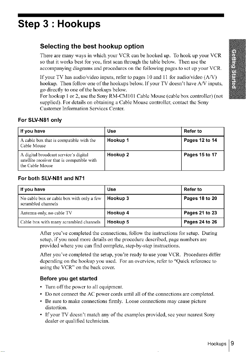
Selecting the best hookup option
There are many ways in which your VCR can be hooked up. To hook up your VCR
so that it works best for you, first scan through the table below. Then use the
accompanying diagrams and procedures on the following pages to set up your VCR.
If your TV has audio/video inputs, refer to pages 10 and 11 for audio/video (A/V)
hookup. Then follow one of the hookups below. If your TV doesn't have A/V inputs,
go directly to one of the hookups below.
For hookup 1 or 2, use the Sony RM-CM 101 Cable Mouse (cable box controller) (not
supplied). For details on obtaining a Cable Mouse controller, contact the Sony
Customer information Services Center.
For SLV-N81 only
If you have Use Refer to
A cable box that is compatible with the Hookup 1 Pages 12 to 14
Cable Mouse
A digital broadcast servicers digital Hookup 2 Pages 15 to 17
satellite receiver that is compatible with
the Cable Mouse
For both SLV-N81 and N71
If you have Use Refer to
No cable box or cable box with only a few Hookup 3 Pages 18 to 20
scrambled channels
Antenna only, no cable TV Hookup 4 Pages 21 to 23
Cable box with ma W scrambled channels Hookup 5 Pages 24 to 26
After you've completed the connections, follow the instructions for setup. During
setup, if you need more details on the procedure described, page numbers are
provided where you can find complete, step_by_step instructions.
After you've completed the setup, you're ready to use your VCR. Procedures difl'er
depending on the hookup you used. For an overview, refer to "Quick reference to
using the VCR" on the back cover.
Before you get started
• Turn off the power to all equipment.
• Do not connect the AC power cords until all of the connections are completed.
• Be sure to make connections filmly. Loose connections may cause picture
distortion.
• If your TV doesn't match any of the examples provided, see your nearest Sony
dealer or qualified technician.
Hookups I 9
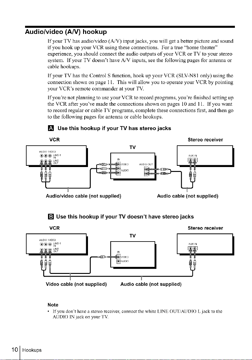
Audio/video (A/V) hookup
If your TV has audio/video (A/V) input jacks, you will get a better picture and sound
if you hook up your VCR using these connections. For a true "home theater"
experience, yot_ should connect the audio outputs of your VCR or TV to your stereo
system. If your TV doesn't have A/V inputs, see the following pages for antenna or
cable hookups.
If your TV has the Control S function, hook up your VCR (SLV-N81 only) using the
connection shown on page 11. This will allow you to operate your VCR by pointing
yotw VCR's remote commander at your TV.
If you're not planning to use yotw VCR to record programs, you're finished setting up
the VCR after you've made the connections shown on pages 10 and 11. If you want
to record regular or cable TV programs, complete these connections first, and then go
to the following pages for antenna or cable hookups.
[] Use this hookup if your TV has stereo jacks
VCR
Audio/video cable (not supplied)
Stereo receiver
AUDIO O T
r
Audio cable (not supplied)
10 Hookups
[] Use this hookup if your TV doesn't have stereo jacks
VCR Stereo receiver
IN V_DEO
AUdiO
Video cable (not supplied)
Note
• lfyoudon_thaveastereoreceiver, connectthewhiteLINEOUTiAUDlOLjacktothe
AUDIO IN jack on your TV.
Audio cable (not supplied)
I
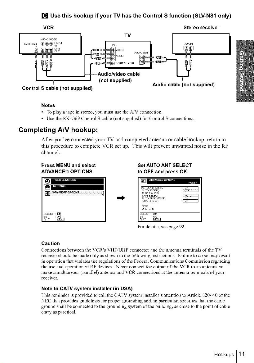
[] Use this hookup if your TV has the Control S function (SLV-N81 only)
VCR Stereo receiver
_Audio/video cable
Control S cable (not supplied)
i Audio cable (not supplied)
Notes
• To play a tape in stereo, you must use the A/V connection.
• Use the RK=G69 (ontrol S cable (not supplied) lbr Control S connections.
Completing A/V hookup:
After you've connected your TV and completed antenna or cable hookup, return to
this procedure to complete VCR set up. This will prevent unwanted noise in the RF
channel.
Press MENU and select
ADVANCED OPTIONS.
SET......
QUIT
I_ ^u× IN
i (not supplied)
Tv
Set AUTO ANT SELECT
to OFF and press OK.
,UTOA_T SELECT
AUTO _TE_EO
TUNERAUDIO
TaPE_E_ECT
AUTOTaPE_EO
NE×T
_UlT
For details, see page 92.
I
Caution
Connections between the VCR's VHFiUHF connector and the antenna terminals of the TV
receiver should be made only as shown in the tbIIowing instructions. Failure to do so may result
in operation that violates the regulations of the Federal Communications Commission regarding
the use and operation of RF devices. Never connect the output of the V(R to an an*enna or
make simultaneous (parallel) antenna and VCR connections at the antenna terminals of your
receiver.
Note to CATV system installer (in USA)
"lhis reminder is provided to call tbe CATV system installer_s attention to Article 820- 40 oftbe
NEC tbat provides guidelines for proper grounding and, in particular, specifies that the cable
ground shall be connected to the groundiz_g system of the building, as close to the point of cable
entry as practical.
Hookups I 11
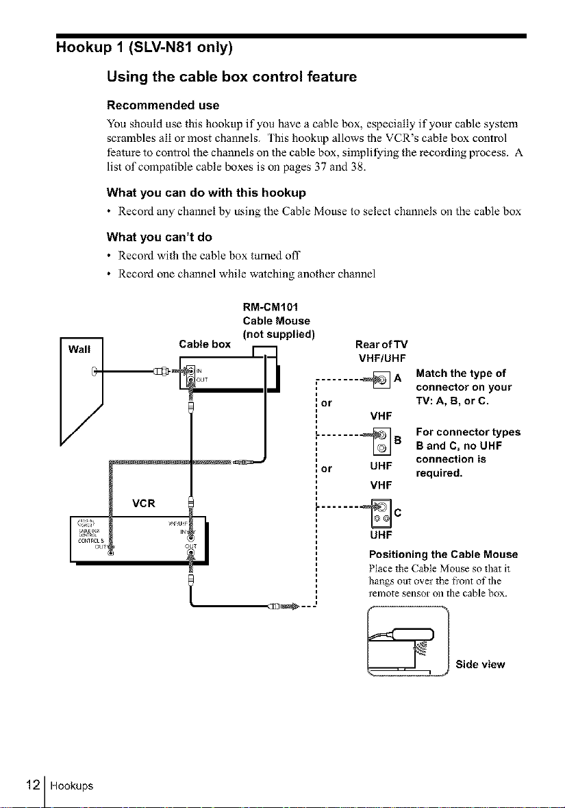
Hookup 1 (SLV-N81 only)
Using the cable box control feature
Recommended use
You should use this hookt_p if you have a cable box, especially if your cable system
scrambles all or most channels. This hookup allows the VCR's cable box control
feattu-e to control the channels on the cable box, simplifying the recording process. A
list of compatible cable boxes is on pages 37 and 38_
What you can do with this hookup
• Record any channel by using the Cable Mouse to select channels on the cable box
What you can't do
• Record with the cable box turned oil"
• Record one channel while watching another channel
Cable box 1- I
RM-CM101
Cable Mouse
(not supplied)
Rear of TV
VHF/UHF
, _A
=
i
{or
VHF
........ _B
{or UHF
VHF
Match the type of
connector on your
TV: A, B, or C.
For connector types
B and C, no UHF
connection is
required.
12 Hookups
t
....... _C
UHF
Positioning the Cable Mouse
Place the Cable Mouse so that it
hangs out over the fi'ont of the
l'el]/Ote SellSOr Oll the cable box.
..CEI_...
Side view
Hookup 1 : VCR setup
Before you start.,.
• Turn on the VCR and the TVI
• Press TV/VIDEO to display the VIDEO indicator in the VCR's display window.
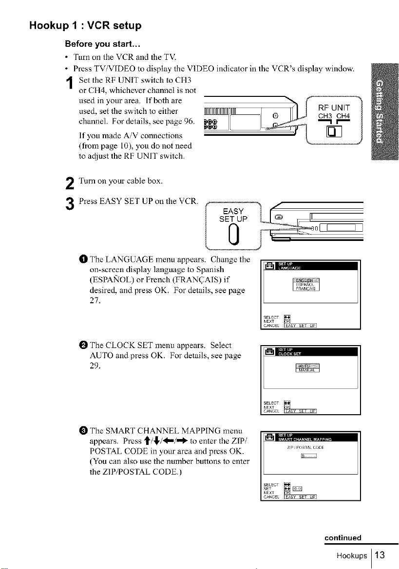
1 Set the RF UNIT switch to CH3
or CH4, whichever channel is not
used inyourarea, lf bothare ,_, , , ,_, ,_,,,@ h _ cRHF3UcNHIT4 ?used, set the switch to either IIIIIIIIIIIIIIIII I
channel. For details, see page 96. _L_ "_l_r_l-"_ I
If you made A/V connections
(from page 10), you do not need
to adjust the RF UNIT switch.
Turn on your cable box.
2
Press EASY SET UP on the VCR.
3
t_ The LANGUAGE menu appears. Change the
on-screen display language to Spanish
(ESPA_IOL) or French (FRAN_AIS) if
desired, and press OK. For details, see page
27.
SET UP
I_ The CLOCK SET menu appears. Select
AUTO and press OK. For details, see page
29.
O The SMART CHANNEL MAPPING menu
appears. Press '_/!'/_"/"_ to enter the ZIP/
POSTAL CODE in yotlr area and press OK.
(You can also use the number buttons to enter
the ZIP/POSTAL CODE.)
=%;',,;,.=
ZP POSTAL CODE
continued
Hookups I 13
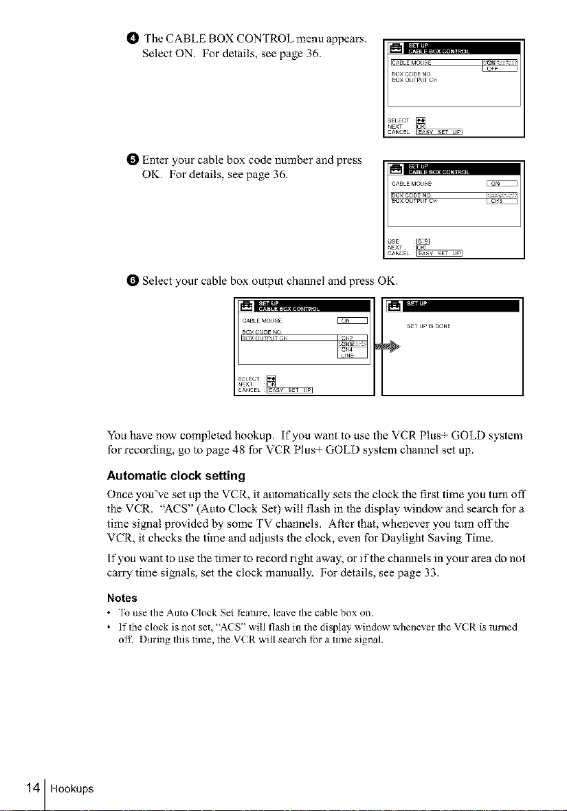
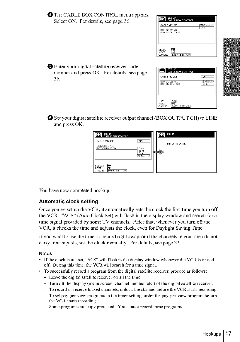
t_ The CABLE BOX CONTROL menu appears.
Select ON. For details, see page 36. _'_1[::_,.................
CABLE MOUSE
8O× CODE NO
8OX OUTPUT Ckl
I_ Enter your cable box code number and press
OK. For details, see page 36.
CABLE MOUSE
SO× CODE NO
80× OUTPUT CH
O Select your cable box output channel and press OK.
CABLE MOUSE
80× CODE NO
80× OUTPUT CH
EgNEEE_
S_T UP IS DONE
÷
You have now completed hookup, if you want to use the VCR Plus+ GOLD system
for recording, go to page 48 for VCR Plus+ GOLD system channel set up.
Automatic clock setting
Once you've set up the VCR, it automatically sets the clock the first time you turn off
the VCR. "ACS" (Auto Clock Set) will flash in the display window and search for a
time si_aal provided by some TV channels. After that, whenever you turn off the
VCR, it checks the time and adjusts the clock, even for Daylight Saving Time.
If you want to use the timer to record right away, or if the channels in your area do not
carry time signals, set the clock manually. For details, see page 33.
Notes
• ]o use the Auto Clock Set l_ature, leave the cable box on.
• If the clock is not set, "AC S" will flash in the display window whenever the VCR is turJled
off. During this time, the VCR will sem'ch for a time signal.
IN|
14 Hookups
Hookup 2 (SLV-N81 only)
Connecting to a digital satellite receiver
Recommended use
Use this hookup if you have a digital satellite receiver that is compatible with the
Cable Mouse. it allows the VCR's cable box control feature to control the channel on
the digital satellite receiver, simplifying the recording process. A list of compatible
digital satellite receivers is on page 39.
What you can do with this hookup
• Record any channels by using the Cable Mouse to select channels on the digital
satellite receiver
What you can't do
• Record with the digital satellite receiver turned off
• Record any channels fi-om cable or an antenna ('1_ record channels from cable or
an antenna, turn offthe cable box control feature.)
• Use a cable box
• Record programs with the VCR Plus+ GOLD system ('1_ use the VCR PlusT
GOLD system, turn off the cable box control feature.)
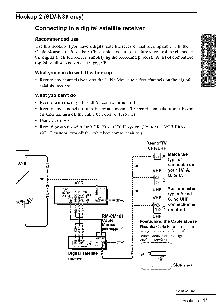
Rear of TV
VHF/UHF
,....... _ A Match the
, or connector on
type of
VHF your TV: A,
Digital satellite
receiver
" ...... _B B, or C.
, or UHF For connector
types B and
VHF C, no UHF
........ _ connection isC required.
UHF
Positioning the Cable Mouse
Place the (" _bte Mouse so that it
hangs out over the fi'ont of the
remote sensor on the digital
satellite receiver.
_ Side view
continued
Hookups ] 15
Hookup 2 : VCR setup
Before you start.,,
• Turn on the VCR and the TV:
• Press TV/VIDEO to display the VIDEO indicator in the VCR's display window.
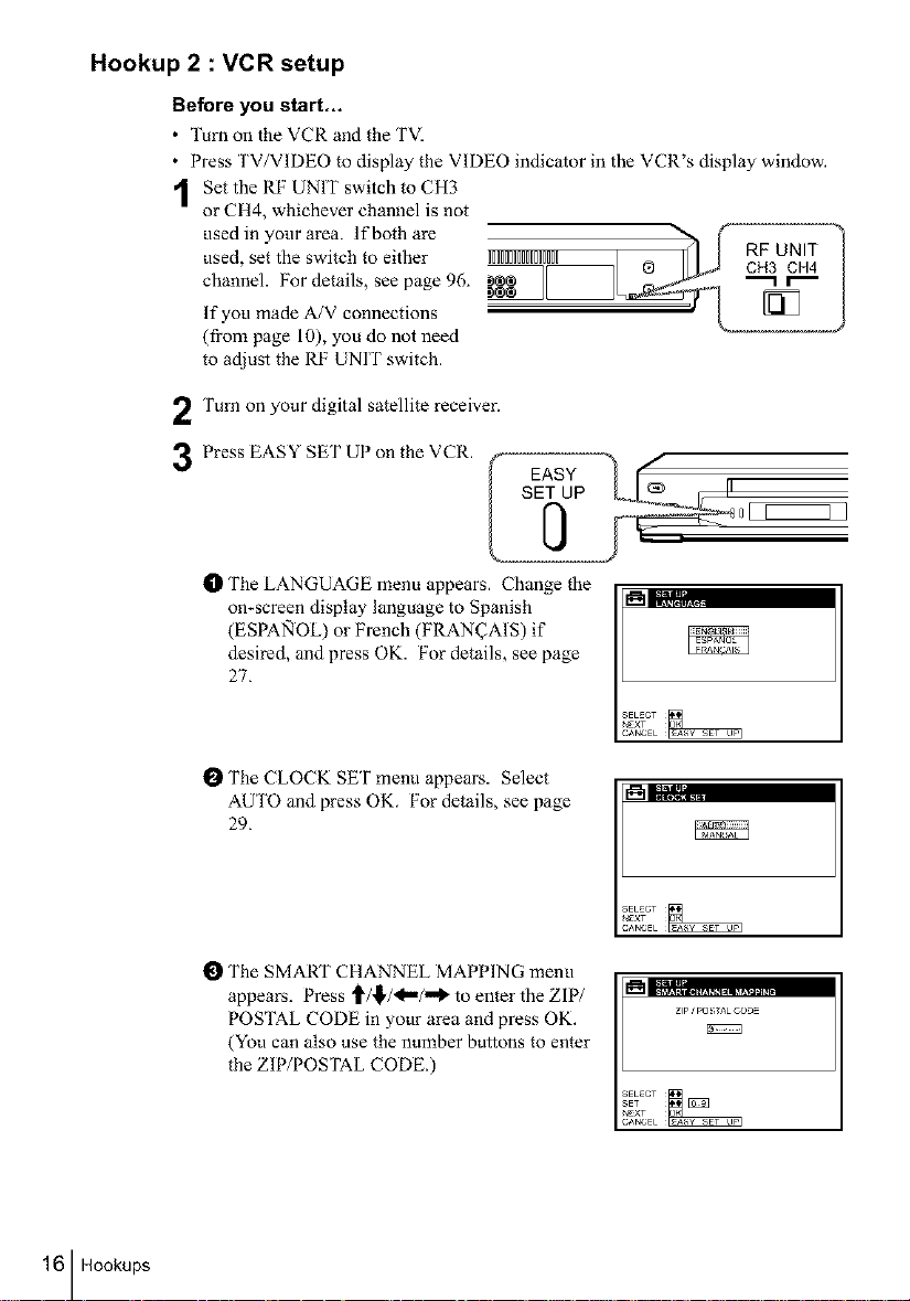
Set the RF UNIT switch to CH3
or CH4, whichever channel is not
used, set the switch to either IIIIIIIIIIIIIIII @ CH3 CH4
channel. For details, see page 96. "-1 r"-
used in your area. lfbothare &_ RF_UNIT !
If you made A/V connections
(from page 10), you do not need
to adjust the RF UNIT switch.
Turn on your digital satellite receiver,
3 Press EASYSETUP°ntheVCR' f s_ASuY _)__ , [I-
tD The LANGUAGE menu appears. Change the
on-screen display language to Spanish _'_I;:_.;.,,
(ESPA_IOL) or French (FRAN_AIS) if
desired, and press OK. For details, see page
27.
16 Hookups
I_ The CLOCK SET menu appears. Select
AUTO and press OK. For details, see page
29.
O The SMART CHANNEL MAPPING menu
appears. Press _/,I,/<"/"_ to enter the ZIP/
POSTAL CODE in your area and press OK.
(You can also use the number buttons to enter
the ZIP/POSTAL CODE.)
Zip ¢ pO S;TAL CODE
t_ The CABLE BOX CONTROL menu appears.
Select ON. For details, see page 36. _='-" .................
CABtE _,IOUSE
BOXCODENO
BOX(>_TPUTC_
I_ Enter your digital satellite receiver code
number and press OK. For details, see page
36.
CA_tE_OUSE
B(>XC(>DENO
l_Set your digital satellite receiver output channel(BOX OUTPUT CH)to LINE
and press OK.
CABtE MOUSE
BOXCODE NO
:OXOUTPOSTC_
E2NZZZ3
SET _' i_; O(>r_E
÷
Yon have now completed hookup.
Automatic clock setting
Once you've set up the VCR, it automatically sets the clock the first time you turn off
the VCR. "ACS" (Auto Clock Set) will flash in the display window and search for a
time signal provided by some TV channels. After that, whenever yotl turn off the
VCR, it checks the time and adiusts the clock, even for Daylight Saving Time.
If you want to use the timer to record right away, or if the channels in your area do not
carry time si_aals, set the clock manually. For details, see page 33.
Notes
• If tt_e clock is not set, "ACS" will t'lash i_ tile display window whenever the VCI_. is turned
ofi_ Duri*_g this time, the VCR will search for a time signal.
• To successfully record a program from the digital satellite receiver, proceed as follows:
Leave the digital satellite receiver on all the time.
lure offthe display (menu screen, channel number, etc.) of the digital satellite receiver.
lo record or receive locked channels, u_tock the channel belbre the VCR starts recording.
lo set pay-per-view programs in the timer setti*lg, order the pay-per-view program before
the VCR starts recording.
Some programs are copy protected. You cannot record these programs.
Hookups117
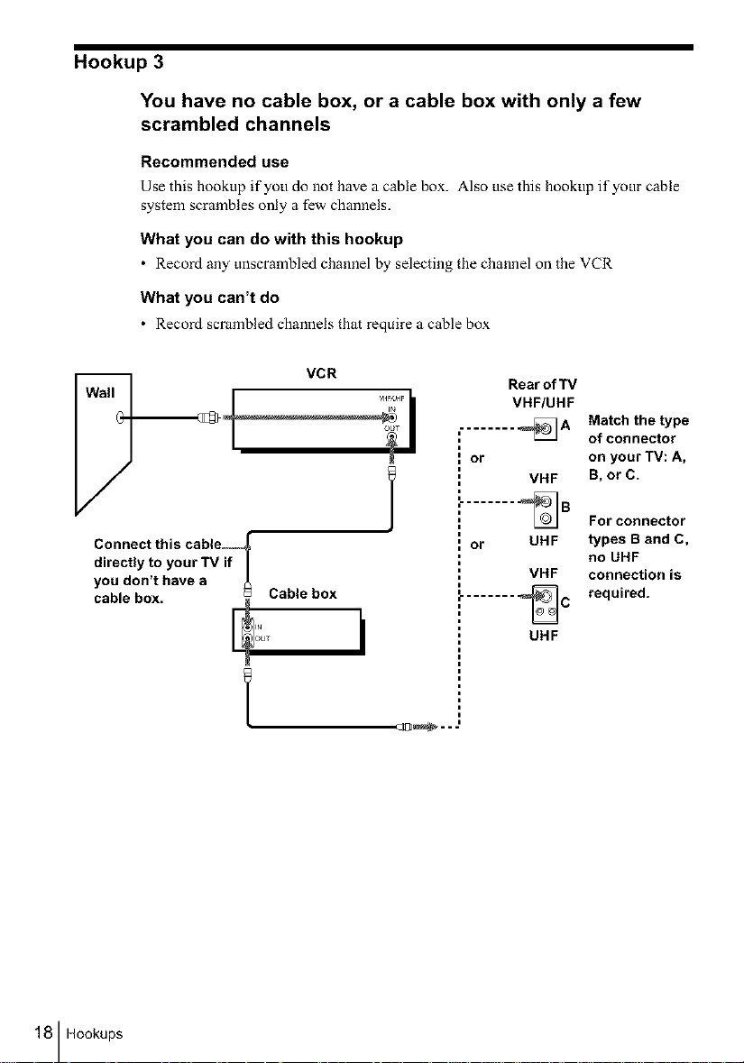
Hookup 3
You have no cable box, or a cable box with only a few
scrambled channels
Recommended use
Use this hookup if yotl do not have a cable box. Also use this hookup if your cable
system scrambles only a few channels.
What you can do with this hookup
• Record any unscrambled channel by selecting the channel on the VCR
What you can't do
• Record scrambled channels that require a cable box
Rear of "iV
VHF/UHF
......... _A
or
VHF
Match the type
of connector
on your TV: A,
B, or C.
Connect this cable,
directly to your TV if
you don't have a
cable box. Cable box
E
c_1_-- J
......... _B
or UHF
i
i
VHF
For connector
types B and C,
no UHF
connection is
required.
18 Hookups
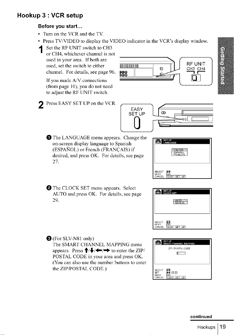
Hookup 3 : VCR setup
Before you start...
• Turn on the VCR and the TVI
• Press TV/VIDEO to display the VIDEO indicator in the VCR's display window.
1 Set the RF UNIT switch to CH3
or CH4, whichever channel is not
used inyourarea, lf bothare ,., . , ,H< ,_,,,® h _ cRF3UNIT _)used, set the switch to either IIIIIIIIIIIIIIIII I
channel. Por details, see page 96. _[_ "_r'_ I
If you made A/V connections
(from page 10). you do not need
to adjust the RF UNIT switch.
Press EASY SET UP on the VCR.
O The LANGUAGE menu appears. Change the
on-screen display language to Spanish
(ESPA_qOL) or French (FRAN(TAIS) if
desired, and press OK. For details, see page
27.
SET UP
I_ The CLOCK SET menu appears. Select
AUTO and press OK. For details, see page
29.
(For SLV-NS1 only)
The SMART CHANNEL MAPPING menu
appears. Press ,_/,_,/<m/_ to enter the ZIP/
POSTAL CODE in yotlr area and press OK.
(You can also use the number buttons to enter
the ZIP/POSTAL CODE.)
zip JPOS,AL COBE
continued
Hookups I 19
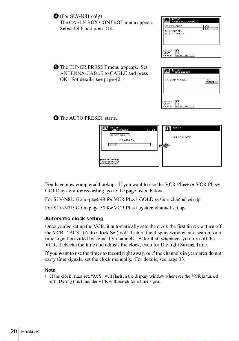
t_ (For SLV=N81 only)
The CABLE BOX CONTROL menu appears.
Select OFF and press OK.
I_ The TUNER PRESET menu appears. Set
ANTENNA/CABLE to CABLE and press
OK. For details, see page 42.
I_ The AUTO PRESET stairs.
_ROCE_;SING
liiiiiiiiiiiiil
PEAS W^
SAB_E MOUSE
80× CODE NO
80× OUTPUT CH
&NTENNAiCADLE
20 Hookups
You have now completed hookup, if you want to use the VCR Plus+ or VCR Plus+
GOLD system for recording, go to the page listed below.
For SLV-N81: Go to page 48 for VCR Plus+ GOLD system channel set up.
For SLV-N71: Go to page 55 for VCR Plus+ system channel set up.
Automatic clock setting
Once you've set up the VCR, it automatically sets the clock the first time you turn off"
the VCR. "ACS" (Auto Clock Set) will flash in the display window and search for a
time si_aal provided by some TV channels. After that, whenever you turn offthe
VCR, it checks the time and adjusts the clock, even for Daylight Saving Time.
If you want to use the timer to record right away, or if the channels in your area do not
carry time signals, set the clock manually. For details, see page 33.
Note
• ]f the clock is not set, "A( S" will flash in the display wit_dow wllenever tile VC R is turned
off. During this time, the V(R will search tbr a time signal.
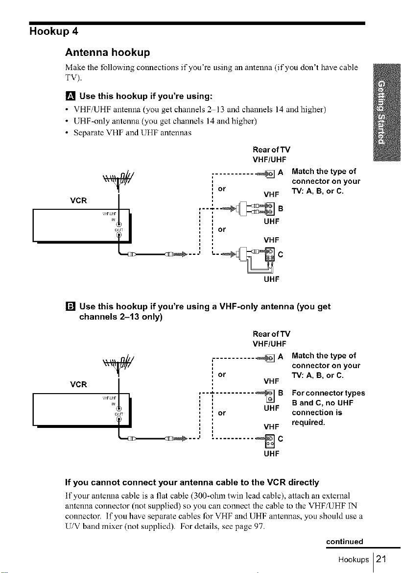
Hookup 4
Antenna hookup
Make the follow ng connect ons fyou re t s ng an antenna ( fyou don t have cable
'PV).
[] Use this hookup if you're using:
• VHF/UHF antenna (you get channels 213 and channels 14 and higher)
• UHF_only antenna (you get channels 14 and higher)
• Separate VHF and UHF antennas
[] Use this hookup if you're using a VHF-only antenna (you get
VCR
'% I : : UHF
out ', ] Or
__...', L._ c
channels 2-13 only)
_/ Or
VCR
'% I : UHF
out i Or
TI i
__---' _ C
Rear of TV
VHF/UHF
or
...... VHFB
UHF
Rear of TV
VHF/UHF
VHF
,--'_ .......... _ B
_===1
UHF
A Match the type of
connector on your
TV: A, B, or C.
A Match the type of
connector on your
TV: A, B, or C.
For connector types
B and C, no UHF
connection is
required.
If you cannot connect your antenna cable to the VCR directly
If yotw antenna cable is a flat cable (300-ohm twin lead cable), attach an external
antenna connector (not supplied) so you can connect the cable to the VHF/UHF IN
connector, if you have separate cables for VHF and UHF antennas, you should use a
U/V band mixer (not supplied). For details, see page 97.
continued
Hookups121
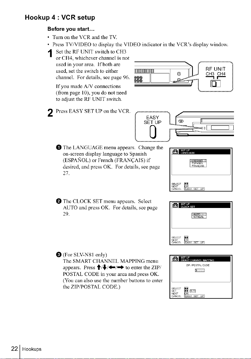
Hookup 4 : VCR setup
Before you start.,,
• Turn on the VCR and the TVI
• Press TV/VIDEO to display the VIDEO indicator in the VCR's display window.
Set the RF UNIT switch to CH3
or CH4, whichever channel is not
used, set the switch to either IIIIIIIIIIIIIIII @ CH3 CH4
channel. For details, see page 96. "-1 r"-
usedin your area. If both are &_ RFr_UNIT !
If you made A/V connections
(from page 10), you do not need
to adjust the RF UNIT switch.
Press EASY SET UP on the VCR. f _ /
t1_ The LANGUAGE menu appears. Change the
on-screen display language to Spanish _%'_117,:_2,,,,
(ESPA_IOL) or French (FRAN_AIS) if
desired, and press OK. For details, see page
27.
0[
EASY
22 Hookups
I_ The CLOCK SET menu appears. Select
AUTO and press OK. For details, see page
29.
O (For SLV-N81 only)
The SMART CHANNEL MAPPING menu
appears. Press _/_/_/_ to enter the ZIP/
POSTAL CODE in your area and press OK,
(You can also use the number buttons to enter
the ZIP/POSTAL CODE.)
L.;; ........................
ZIp ' pO !;TAL CODE
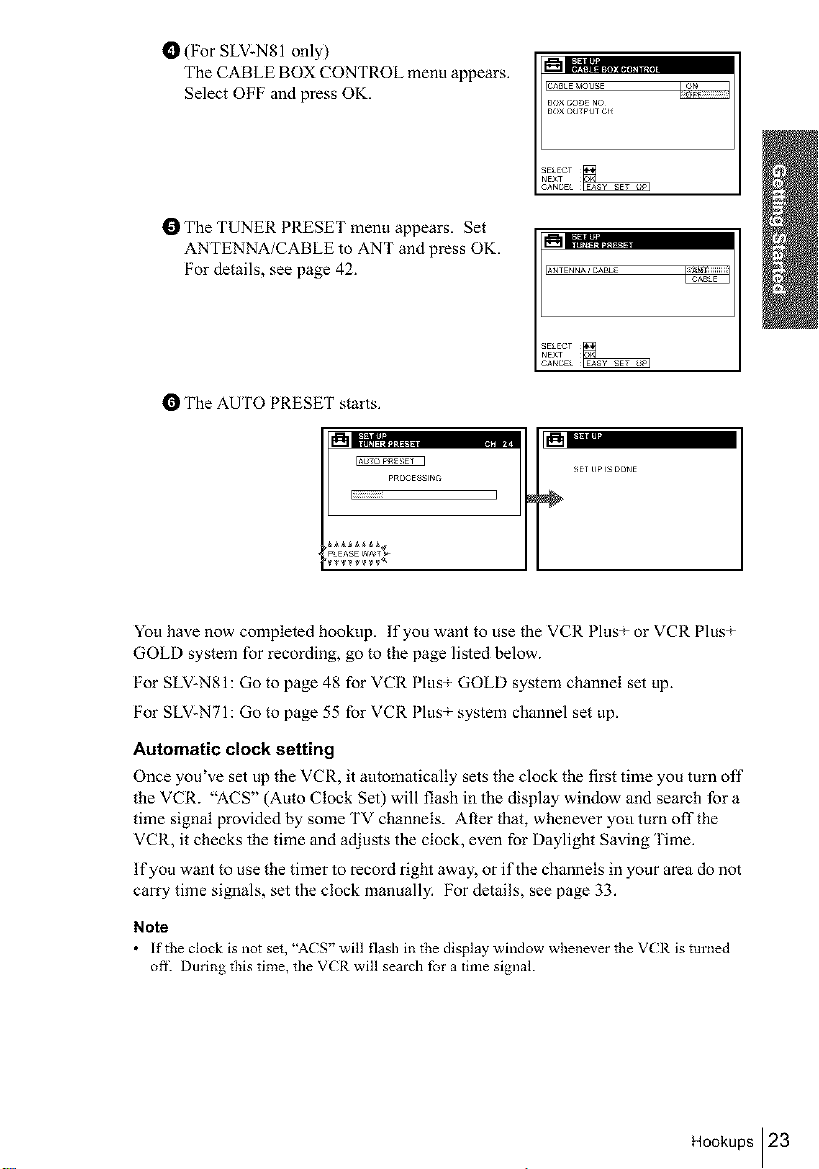
O (For SLV:N81 only)
The CABLE BOX CONTROL menu appears.
Select OF[:' and press OK.
BOX CODE NO
I_ The TUNER PRESET menu appears. Set
ANTENNA/CABLE to ANT and press OK.
[:'or details, see page 42.
I_'.=-iLT;....
ANTENN_CABLE
I_ The AUTO PRESET starts.
pROCESSlr_
liiiiiiiiiiiiil
pLEASE WA_T_
You have now completed hookup. If you want to use the VCR PlusT or VCR PlusT
GOLD system for recording, go to the page listed below.
[:'or SLV-N81: Go to page 48 for VCR PlusT GOLD system channel set up.
[:'or SLV-N71: Go to page 55 for VCR PlusT system channel set up.
Automatic clock setting
Once you've set up the VCR, it automatically sets the clock the first time you turn off
the VCR. "ACS" (Auto Clock Set) will flash in the display window and search for a
time signal provided by some TV channels. After that, whenever yotl turn off the
VCR, it checks the time and adiusts the clock, even for Daylight Saving Time.
ffyou want to use the timer to record right away, or if the channels in your area do not
carry time si_aals, set the clock manually. For details, see page 33.
Note
• [ftt_eclockisnotset,"A(S' willflashi_thedisplaywindow,ahene_ertheV(Risturned
ore Duriz_g this time, the VCR will search for a time signal.
Hookups 123
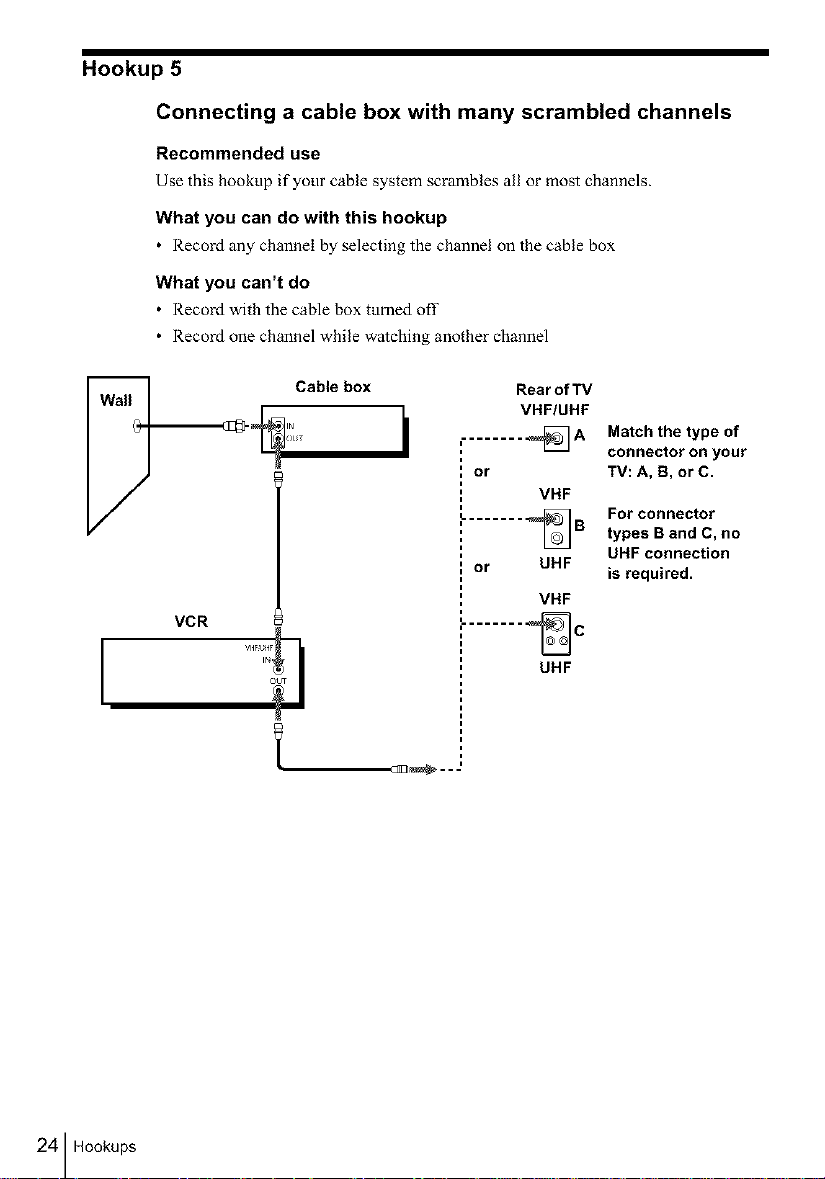
Hookup 5
Connecting a cable box with many scrambled channels
Recommended use
Use this hookup if your cable system scrambles all or most channels_
What you can do with this hookup
• Record any channel by selecting the channel on the cable box
What you can't do
• Record with the cable box ttmaed off
• Record one channel while watching another channel
VCR
Rear of TV
VHF/UHF
........ _A
or
L....... %B
or UHF
........ _C
Match the type of
connector on your
TV: A, B, or C.
VHF
For connector
types B and C, no
UHF connection
is required.
VHF
UHF
24 Hookups
Hookup 5 : VCR setup
Before you start...
• Turn on the VCR and the TVI
• Press TV/VIDEO to display the VIDEO indicator in the VCR's display window.
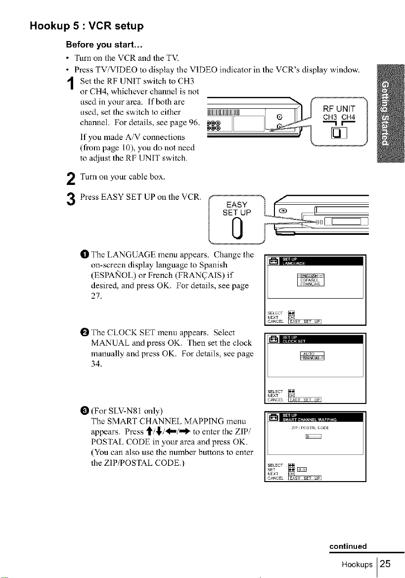
Set the RF UNIT switch to CH3
or CH4, whichever channel is not
used inyourarea, lf bothare ,._ . , ,_< ,_,,_® h _ cRHF3UcNHIT4 ?used, set the switch to either IIIIIIIIIIIIIIIII I
channel. For details, see page 96. _,__
If you made A/V connections
(from page 10), you do not need
to adjust the RF UNIT switch.
Turn on your cable box.
2
Press EASY SET UP on the VCR.
3
tD The LANGUAGE menu appears. Change the
on-screen display language to Spanish
(ESPANOL) or French (FRAN(2AIS) if
desired, and press OK. For details, see page
27.
SET UP o
!_ The CLOCK SET menu appears. Select
MANUAL and press OK. Then set the clock
manually and press OK. For details, see page
34.
O (For SLV-N81 only)
The SMART CHANNEL MAPPING menu
appears. Press _/_./<,m/,,_ to enter the ZIP/
POSTAL CODE in your area and press OK.
(You can also use the number buttons to enter
the ZIP/POSTAL CODE.)
zip JPOSTAL COBE
continued
Hookups 125
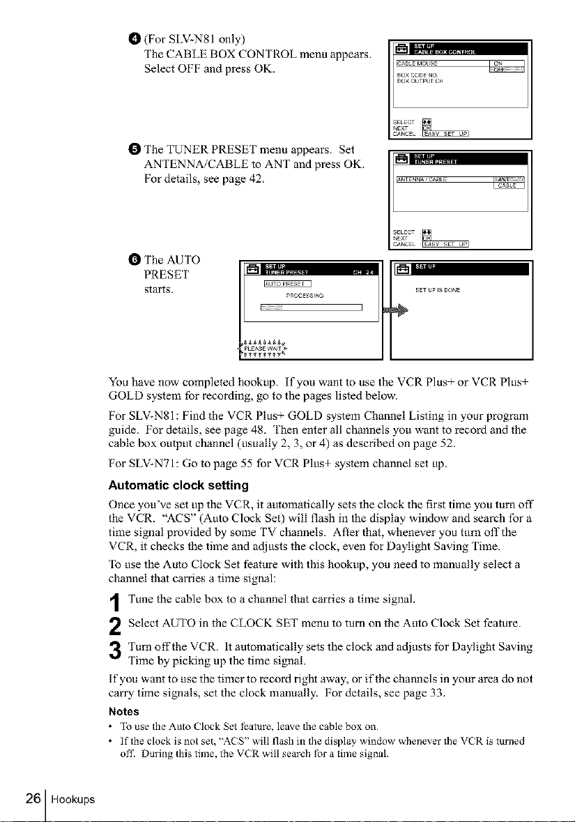
t_ (For SLV2N81 only)
The CABLE BOX CONTROL menu appears.
Select OFF and press OK.
SAB_E MOUSE
80× CODE NO
80× OUTPUT CH
I_ The TUNER PRESET menu appears. Set
ANTENNA/CABLE to ANT and press OK.
For details, see page 42.
_i;L,'; ......
&NTENNAiCADLE
CABL_
I_ The AUTO
PRESET
starts.
_ROCE_;SlNG
I_iiiiiiiiiiiiil
P EAS W^
You have now completed hookup, if you want to use the VCR Plus+ or VCR Plus+
GOLD system for recording, go to the pages listed below.
For SLV-N81: Find the VCR Plus GOLD system Channel Listing in your program
guide. For details, see page 48. Then enter all channels you want to record and the
cable box output channel (usually 2, 3, or 4) as described on page 52.
For SLV-NTI: Go to page 55 for VCR Plus+ system channel set up.
Automatic clock setting
Once you've set up the VCR, it automatically sets the clock the first time you turn off
the VCR. "ACS" (Auto Clock Set) will flash in the display window and search for a
time si_aal provided by some TV channels. After that, whenever you turn off the
VCR, it checks the time and adjusts the clock, even for Daylight Saving Time.
To use the Auto Clock Set feature with this hookup, you need to manually select a
channel that carries a time signal:
26 Hookups
Tune the cable box to a channel that carries a time signal.
2 Select AUTO in the CLOCK SET menu to turn on the Auto Clock Set feature.
3Turn off the VCR. It automatically sets the clock and adjusts for Daylight Saving
Time by picking up the time signal.
If you want to use the timer to record right away, or if the channels in your area do not
carry time signals, set the clock manually. For details, see page 33.
Notes
• ]o use the Auto Clock Set I_ature, leave the cable box on,
• If the clock is not set, "A( S" will flash in the display window whenever the VCR is turJled
off. During this time, the VCR will sem'ch for a time signal.
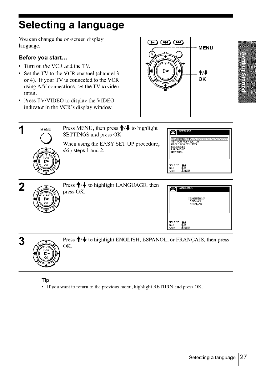
Selecting a language
You can change the on-screen display
language.
Before you start,..
• ]_rn on the VCR and the TV.
• Set the TV to the VCR channel (channel 3
or 4). if your TV is connected to the VCR
using A/V connections, set the TV to video
input.
• Press TV/VIDEO to display the VIDEO
indicator in the VCR's display window.
-- MENU
OK
1
MENU
O
Press MENU, then press t/_ to highlight
SETTINGS and press OK.
When using the EASY SET UP procedure,
skip steps 1 and 2.
SETVCR_IUS_ s_ C_
CABLE SO× CONTROL
CLO#_ SET
LAN_;UAGE
:I_5TURN
O
Press _/,_, to highlight LANGUAGE, then
press OK.
SELECT
_ Press '_/,_, to highlight ENGLISH, ESPANOL, or FRAN_AIS, then press
@
Tip
OK.
If you _aant to return to the pre_ ious menu, highlight RE I'URN and press OK.
Selecting a language 127
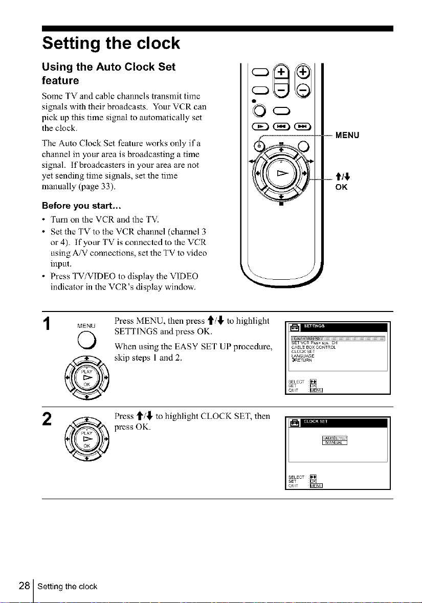
Setting the clock
Using the Auto Clock Set
feature
Some TV and cable channels transmit time
signals with their broadcasts. Yot_r VCR can
pick up this time signal to automatically set
the clock.
The Auto Clock Set feature works only ifa
channel in your area is broadcasting a time
signal. If broadcasters in your area are not
yet sending time signals, set the time
manually (page 33).
Before you start,..
• Turn on the VCR and the TVI
• Set the TV to the VCR channel (channel 3
or 4). If your TV is connected to the VCR
using A/V connections, set the TV to video
input.
• Press TVYVIDEO to display the VIDEO
indicator in the VCR's display window.
MENU
©
Press MENU, then press _/,_, to highlight
SETTINGS and press OK.
When using the EASY SET UP procedure,
skip steps 1 and 2.
_ } I "ll"II I("If"
C j _tm| lira
V
-- MENU
_%..,
I-
SE, VCR pI_ sys CH
CABLEBO×CONT_Ot
C_OCKSET
LANGUAGE
_¢_ETU_N
OK
28 Setting the clock
Press t_/,_,to highlight CLOCK SET, then
press OK.
OK.
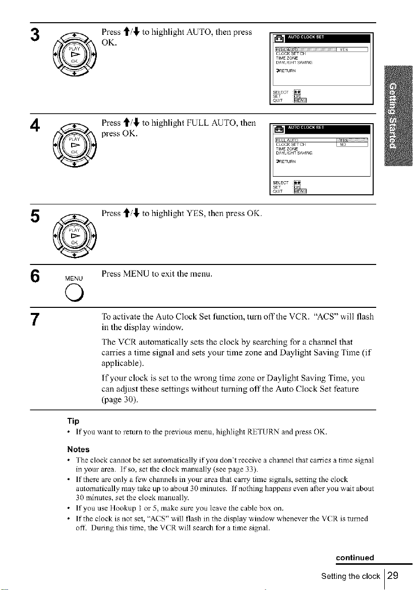
3 @ Press _/,_ to highlight AUTO, then press
Press _/,_, to highlight FULL AUTO, then
press OK.
5 @ Press _/,_, to highlight YES, then press OK.
MENU Press MENU to exit the menu.
O
CLOC_ SET CH
TIMEZOr_E
DAYI IGHT _'Vlr_G
_ETURN
7
Tip
Notes
• The clock camlot be set autum_icatly it'you don't receive a channel that can'ies a time signal
• If there are only a few channels in your area tb_ carry time signals, settling the clock
• If you use Hookup I or 5, make sure you leave the cable box on.
• If the clock is not set, "ACS" will flash i_ the display window wbenever the VCR is turned
To activate the Auto Clock Set function, turn off the VCR. "ACS" will flash
in the display window.
The VCR automatically sets the clock by searching for a channel that
carries a time signal and sets your time zone and Daylight Saving Time (if
applicable).
If your clock is set to the wrong time zone or Daylight Saving Time, you
can adjust these settings without turning offthe Auto Clock Set feature
(page 30).
[f you _aant to retm'n to the pre_ ious menu, highlight RE I'URN and press OK.
in your area. If so, set the clock manually (see page 33).
automatically may take up tu about 30 minutes. If nothing happens even al_er you wait about
30 minutes, set the clock manually.
ofiL Duri_g this time, the VCR will search for a time signal.
continued
Setting the clock 129
I
If the clock does not activate
"_(Z) (Z)
1
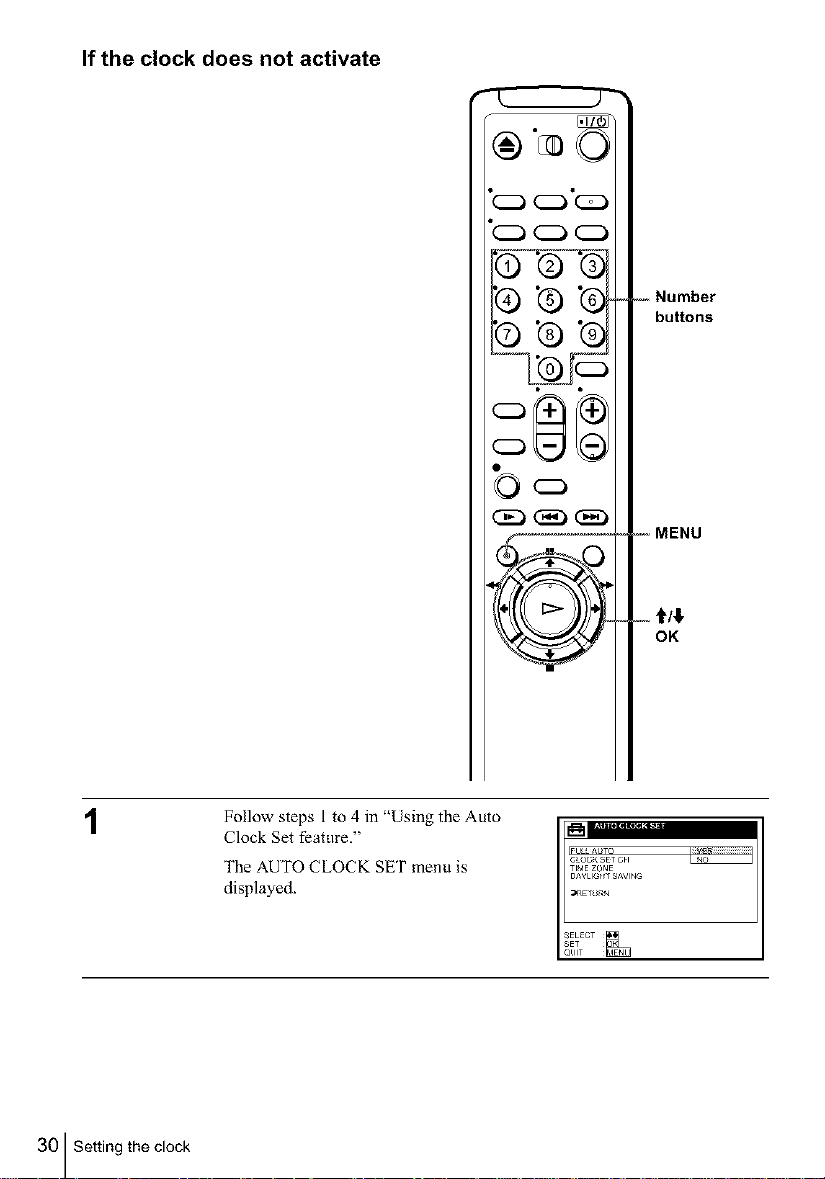
Follow steps l to 4 in "Using the Auto
Clock Set feature."
The AUTOCLOCKSETmenu is
displayed.
_) "G"G
©'G'G
FULLAUTO
C_OCKSETCH
TIMEZONE
DAYLIG_TSAVING
-- Number
buttons
-- MENU
- t/$
OK
30 Setting the clock
 Loading...