

Sony SLV-E830B, SLV-E830NP, SLV-E830VC1, SLV-E830VC2 Service Manual

SLV-E830B/E830NP/E830VC1/E830VC2
RMT-V224/V224B
SERVICE MANUAL
G
j
• Refer to the SERVICE MANUAL of VHS MECHANICAL
ADJUSTMENTS for MECHANICAL ADJUSTMENTS.
(9-921-647-11)
SPECIFICATIONS
French Model
SLV-E830B
Spanish Model
SLV-E830NP
Germany Model
SLV-E830VC1/E830VC2
S MECHANISM
MICROFILM
VIDEO CAMERA RECORDER

FEATURE DIFFERENCE
MODEL NAME (SLV -)
SAFETY SECAM (REC/PB)
ME-SECAM (REC/PB)
ACS (¢: ACA)
TUNER (BTF-)
SYSTEM 1
STEREO
SYSTEM 2
STEREO
RF OUT SYS
REMOTE COMMANDER (RMT-)
E830VC1
¢
BG
ZWEI
G
V224
3WC402
E830VC2
¢
BG
ZWEI
G
V224
E830NP
®
WC411
BG
N/Z
G
V224
E830B
®/®
G/®
®
3WC443
L
NI
BG
ZWEI
L/G
V224B
SAFETY-RELATED COMPONENT WARNING!!
COMPONENTS IDENTIFIED BY MARK ! OR DO TTED LINE WITH
MARK ! ON THE SCHEMATIC DIAGRAMS AND IN THE PARTS
LIST ARE CRITICAL TO SAFE OPERATION. REPLACE THESE
COMPONENTS WITH SONY PARTS WHOSE PART NUMBERS
APPEAR AS SHOWN IN THIS MANUAL OR IN SUPPLEMENTS
PUBLISHED BY SONY.
SAFETY CHECK-OUT
After correcting the original service problem, perform the following
safety checks before releasing the set to the customer.
1. Check the area of your repair for unsoldered or poorly-soldered
connections. Check the entire board surface for solder splashes
and bridges.
2. Check the interboard wiring to ensure that no wires are
"pinched" or contact high-wattage resistors.
3. Look for unauthorized replacement parts, particularly
transistors, that were installed during a previous repair . Point
them out to the customer and recommend their replacement.
4. Look for parts which, through functioning, show obvious signs
of deterioration. Point them out to the customer and
recommend their replace-ment.
5. Check the B+ voltage to see it is at the values specified.
6. Flexible Circuit Board Repairing
• Keep the temperature of the soldering iron around 270˚C
during repairing.
• Do not touch the soldering iron on the same conductor of the
circuit board (within 3 times).
• Be careful not to apply force on the conductor when soldering
or unsoldering.
— 2 —

TABLE OF CONTENTS
SERVICE NOTE
1. ERROR CODE INDICATION··········································· 5
1. GENERAL
Getting Started
Unpacking··············································································1-1
Setting up the remote commander ·········································1-1
Connecting the VCR······························································1-2
Tuning your TV to the VCR ······················································1-3
Setting up the VCR with the Auto Set Up function ···············1-4
Setting the clock ····································································1-4
Manual setup — Selecting a language···································1-5
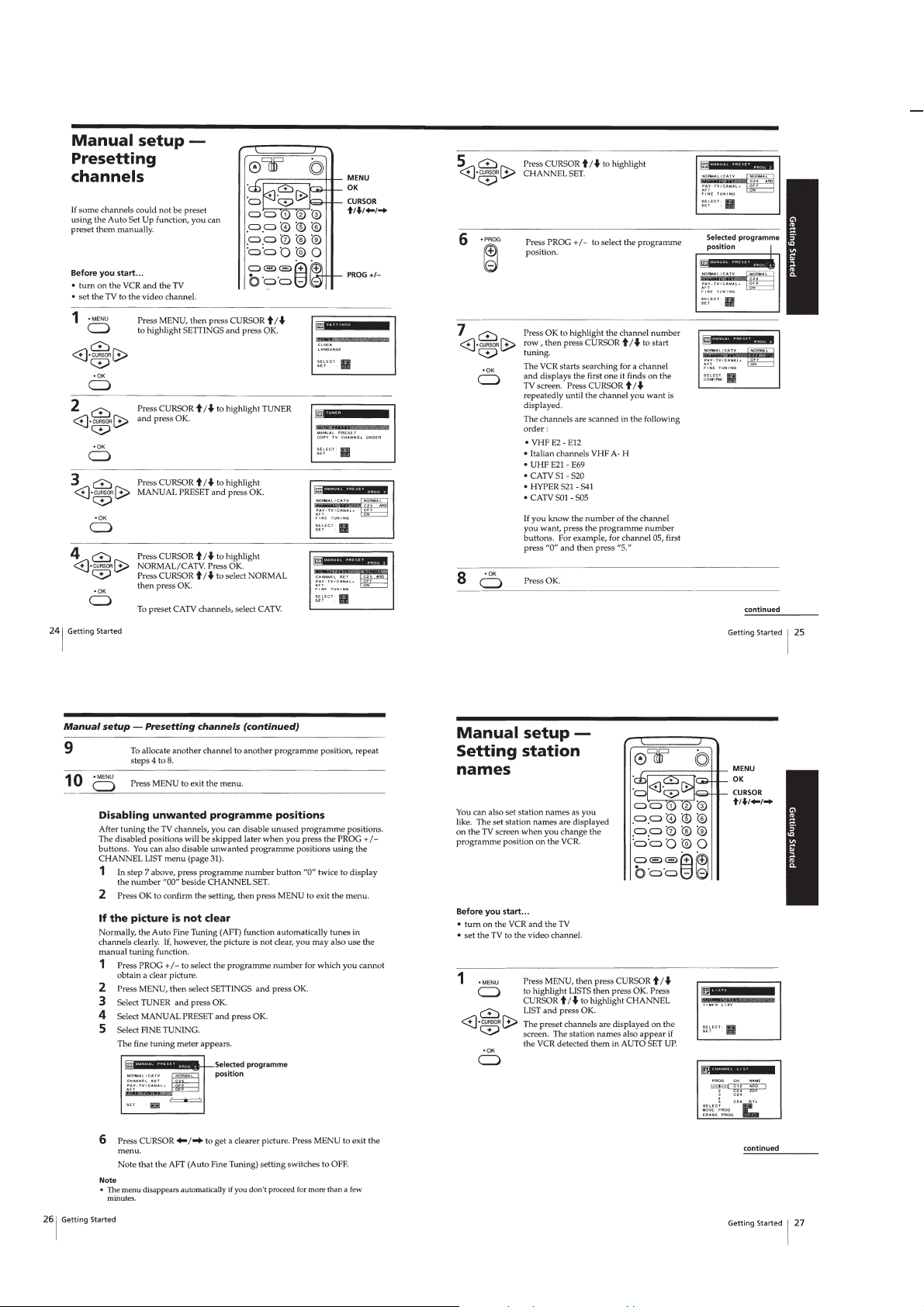
Manual setup — Presetting channels·····································1-6
Manual setup — Setting station names ································· 1-6
Manual setup — Changing/disabling programme positions ·1-7
Manual setup — Listing the channels as the TV ···················1-8
Connecting the Satellite tuner················································1-8
Setting the PAY-TV/Canal Plus decoder································1-9
Basic Operations
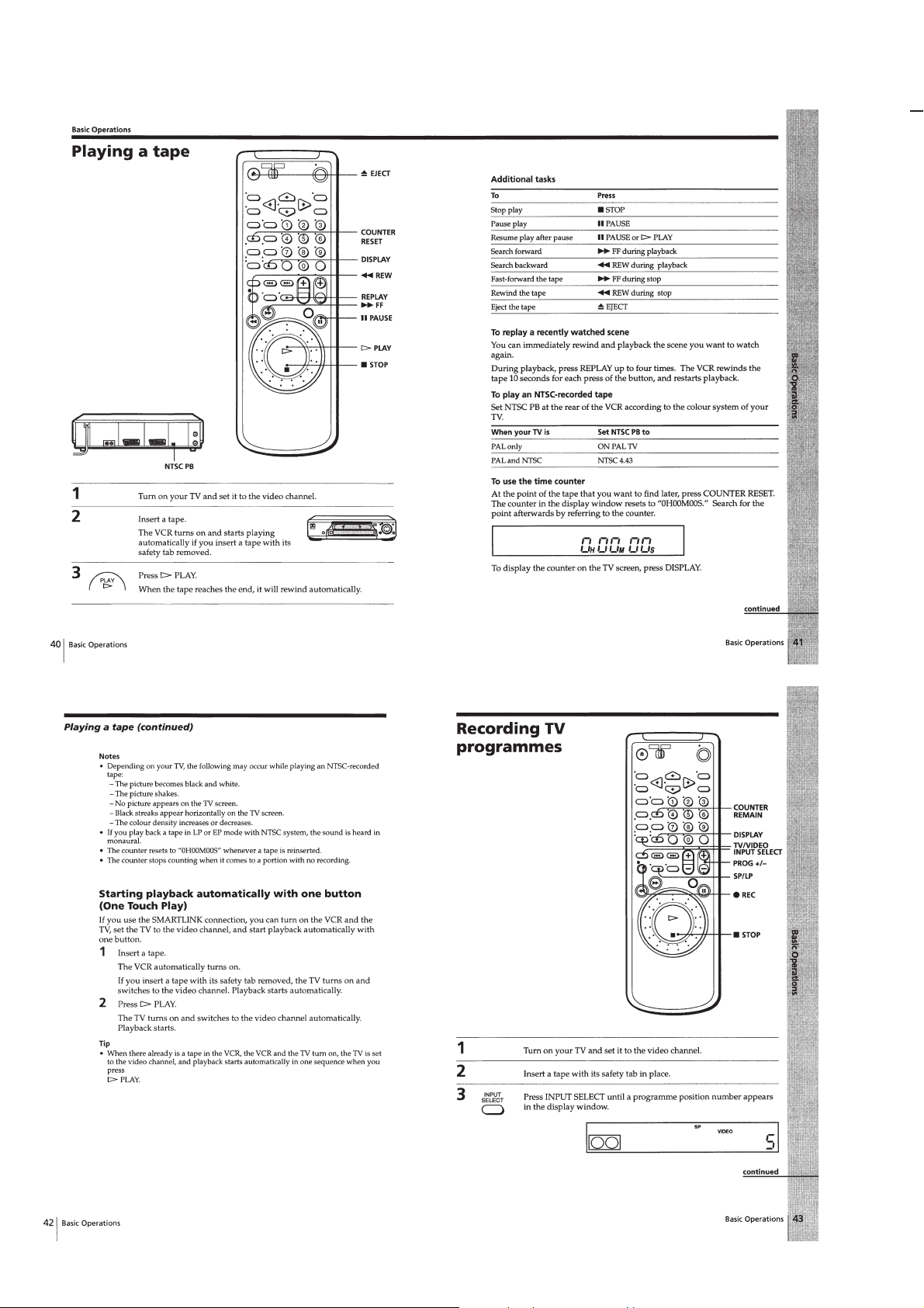
Playing a tape·······································································1-10
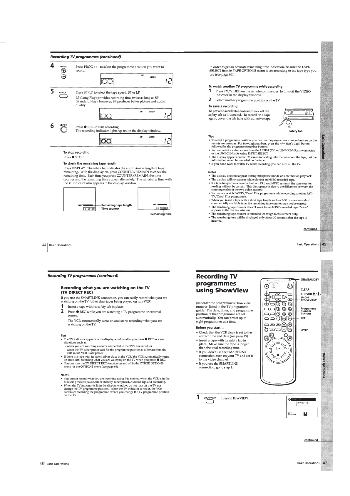
Recording TV programmes ·················································1-10
Recording TV programmes using ShowView ·····················1-11
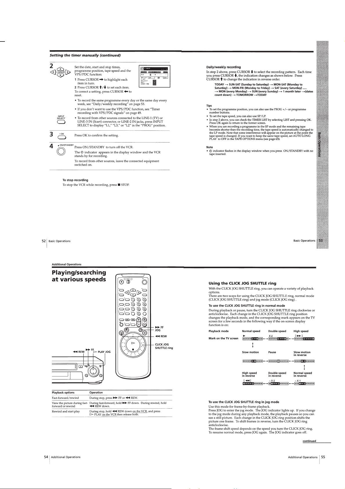
Setting the timer manually···················································1-12
Additional Operations
Playing/searching at various speeds ····································1-13
Recording TV programmes using the quick timer ·············· 1-14
Checking/changing/cancelling timer settings ······················1-14
Recording stereo and bilingual programmes ······················· 1-15
Searching using the index function······································1-15
Adjusting the picture ···························································1-15
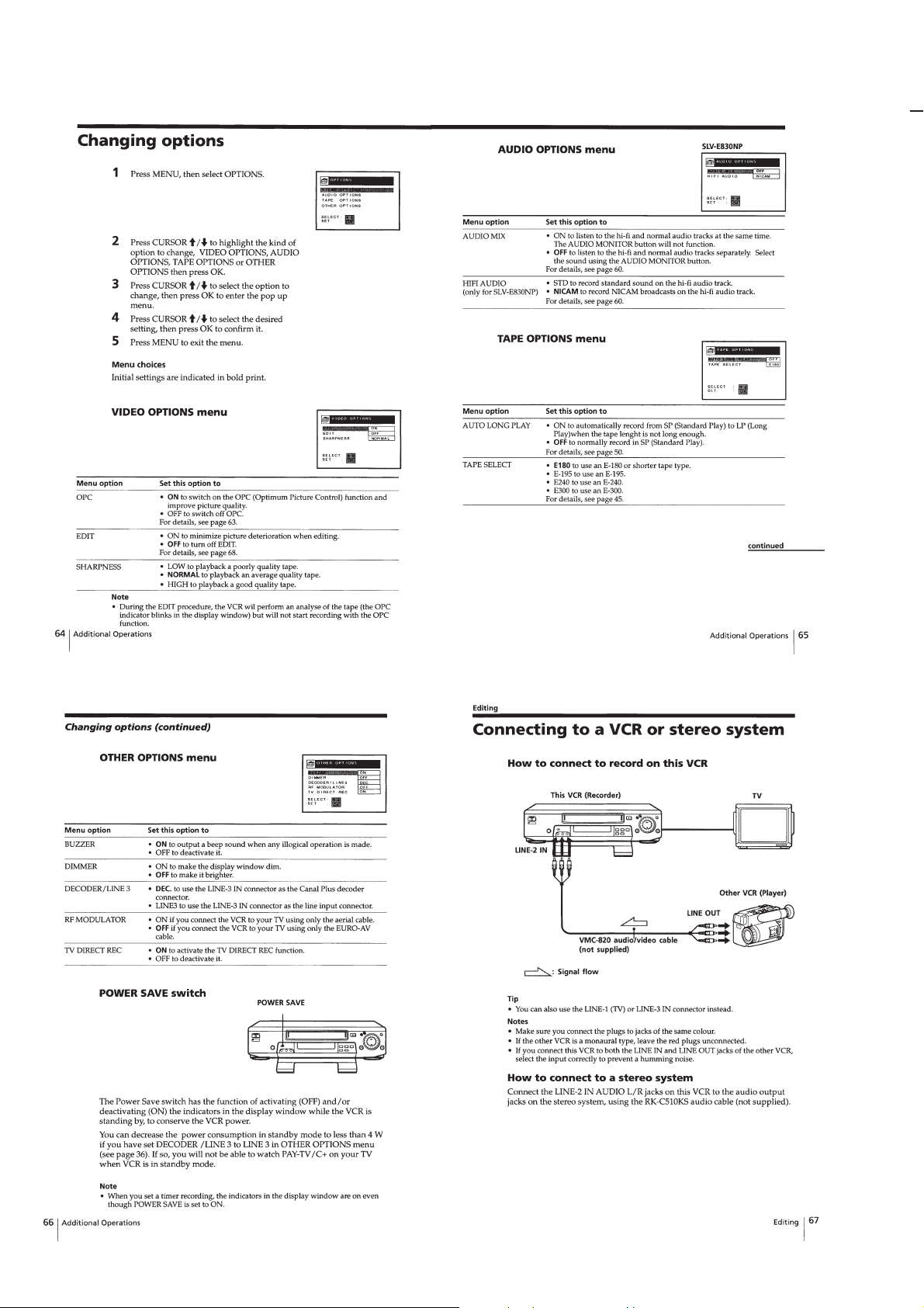
Changing options ·································································1-16
Editing
Connecting to a VCR or stereo system································1-16
Basic editing ········································································1-17
Audio dubbing ·····································································1-17
Additional Information
Index to parts and controls··················································· 1-17
2. DISASSEMBLY
2-1. UPPER CASE, FRONT PANEL BLOCK ASSEMBLY·2-1
2-2. FR-128 BOARD, DM-73 BOARD ·································2-1
2-3. REAR PANEL ·································································2-1
2-4. POWER BLOCK, MA-316 BOARD
(WITH S MECHANISM DECK) ···································2-2
2-5. RP-231 BOARD, S MECHANISM DECK ····················2-2
2-6. INTERNAL VIEWS························································2-3
2-7. CIRCUIT BOARDS LOCATION···································2-4
3. BLOCK DIAGRAMS
3-1. OVERALL BLOCK DIAGRAM ····································3-1
3-2. VIDEO BLOCK DIAGRAM ··········································3-3
3-3. SERVO/SYSTEM CONTROL BLOCK DIAGRAM ·····3-5
3-4. AUDIO BLOCK DIAGRAM ··········································3-7
3-5. MODE CONTROL BLOCK DIAGRAM ·······················3-9
3-6. TUNER BLOCK DIAGRAM ······································· 3-11
3-7. POWER SUPPLY BLOCK DIAGRAM ·······················3-13
4. PRINTED WIRING BOARDS AND
SCHEMATIC DIAGRAMS
4-1. FRAME SCHEMATIC DIAGRAM································4-1
4-2. PRINTED WIRING BOARDS AND
SCHEMATIC DIAGRAMS ············································4-3
• RP-231 (REC/PB AMP)
PRINTED WIRING BOARD ·························4-3
• RP-231 (REC/PB AMP) SCHEMATIC DIAGRAM ····4-5
• MA-316 (VIDEO, SERVO/SYSTEM CONTROL,
AUDIO, TUNER)
PRINTED WIRING BOARD ·························4-8
• MA-316 (VIDEO, NORMAL AUDIO)
SCHEMATIC DIAGRAM ····························4-11
• MA-316 (SERVO/SYSTEM CONTROL)
SCHEMATIC DIAGRAM·········································· 4-14
• MA-316 (ON SCREEN DISPLAY)
SCHEMATIC DIAGRAM ····························4-17
• MA-316 (AFM AUDIO) SCHEMATIC DIAGRAM ·4-19
• MA-316 (TUNER) SCHEMATIC DIAGRAM ·········· 4-21
• MA-316 (FOLLOW TV, PDC, VPS)
SCHEMATIC DIAGRAM ····························4-23
• MA-316 (I/O) SCHEMATIC DIAGRAM ··················4-25
• FR-128 (MODE CONTROL)
PRINTED WIRING BOARD ·······················4-29
• FR-128 (MODE CONTROL)
SCHEMATIC DIAGRAM ····························4-31
• SE-69 (SECAM VIDEO SIGNAL PROCESS)
SCHEMATIC DIAGRAM ····························4-33
• SE-69 (SECAM VIDEO SIGNAL PROCESS)
PRINTED WIRING BOARD ·······················4-35
• DM-73 (OPERATION SWITCHES)
PRINTED WIRING BOARD ·······················4-36
• DM-73 (OPERATION SWITCHES)
SCHEMATIC DIAGRAM ····························4-37
• POWER BLOCK SR826 (SWITCHING REGULATOR)
PRINTED WIRING BOARD ·······················4-39
• POWER BLOCK SR826 (SWITCHING REGULATOR)
SCHEMATIC DIAGRAM ····························4-41
5. INTERFACE,
IC PIN FUNCTION DESCRIPTION
5-1. SYSTEM CONTROL —
VIDEO BLOCK INTERFACE
(MA-316 BOARD IC160)···············································5-1
5-2. SYSTEM CONTROL —
SERVO PERIPHERAL CIRCUIT INTERFACE
(MA-316 BOARD IC160)···············································5-1
5-3. SYSTEM CONTROL —
MECHANISM INTERFACE
(MA-316 BOARD IC160)···············································5-2
5-4. SYSTEM CONTROL —
SYSTEM CONTROL PERIPHERAL CIRCUIT
INTERFACE (MA-316 BOARD IC160) ························5-2
5-5. SYSTEM CONTROL —
AUDIO BLOCK INTERFACE
(MA-316 BOARD IC160)···············································5-2
5-6. SERVO/SYSTEM CONTROL MICROPROCESSOR
PIN FUNCTIONS (MA-316 BOARDS IC160)··············5-3
5-7. TUNER/TIMER MODE CONTROL PIN FUNCTIONS
(FR-128 BOARD IC180) ················································5-4
6. ADJUSTMENTS
6-1. MECHANICAL ADJUSTMENTS ·································6-1
6-2.. ELECTRICAL ADJUSTMENTS ···································6-1
2-1. PREPARATION BEFORE ADJUSTMENT ···················6-1
2-1-1.Equipment Required ························································6-1
2-1-2.Equipment Connection ····················································6-1
2-1-3.Input Signal Check ··························································6-1
2-1-4.Alignment Tape ·······························································6-1
2-1-5.Input/Output Levels and Impedance ······························· 6-2
2-1-6.Adjustment Sequence ······················································6-2
2-2. POWER SUPPLY CHECK ·············································6-2
2-2-1.Output Voltage Check (MA-316 Board) ·························6-2
2-3. SERVO SYSTEM CHECK ·············································6-2
— 3 —

2-3-1.RF Switching Position/
AF Switching Position Adjustments
(MA-316, RP-231 Boards) ··············································6-2
2-4. VIDEO SYSTEM CHECKS ···········································6-3
2-4-1.X’tal OSC Check (MA-316 Board)·································6-3
2-4-2.SYNC AGC Check (MA-316 Board) ······························6-4
2-4-3.White Clip/Dark Clip Check (MA-316 Board) ···············6-4
2-4-4.Recording Y Level Check (MA-316 Board) ··················· 6-4
2-4-5.Recording Chroma Level Check (MA-316 Board) ·········6-4
2-4-6.Playback Level Check (MA-316 Board) ·························6-5
2-5. AUDIO SYSTEM ADJUSTMENT ·································6-5
2-5-1.ACE Head Adjustment ···················································· 6-5
2-5-2.E-E Output Level Check ················································· 6-5
2-5-3.Overall Output Level and Distortion Factor Check·········6-5
2-5-4.Overall Noise Level Check··············································6-5
2-6. ADJUSTMENT PARTS LOCATION DIAGRAM ·········6-6
7. REPAIR PARTS LIST
7-1. EXPLODED VIEWS ······················································ 7-1
7-1-1.FRONT PANEL ASSEMBLY AND
UPPER CASE SECTION ··············································· 7-1
7-1-2.CHASSIS SECTION······················································· 7-2
7-1-3.MECHANISM DECK-1 ·················································7-3
7-1-4.MECHANISM DECK-2 ·················································7-4
7-1-5.MECHANISM DECK-3 ·················································7-5
7-2. ELECTRICAL PARTS LIST ··········································7-6
— 4 —
SLV-E830B/E830NP/E830VC1/E830VC2
SERVICE NOTE
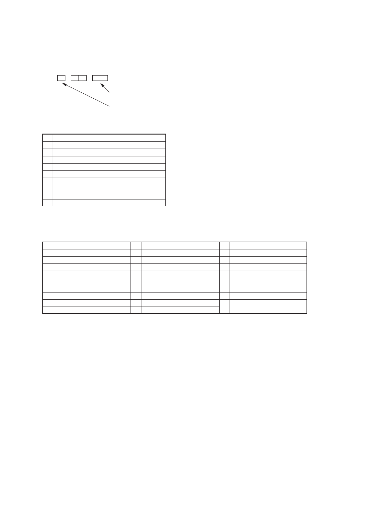
1. ERROR CODE INDICATION
• Error codes are indicated using the lower 5 digits in the fluorescent display tube.
“At this time, Colon “:” between character is not indicated.”
Mode code indication when the error has occurred.
Error code
ERROR CODE
0 No error
1 Cam encoder error Loading direction
2 Cam encoder error Unloading direction
3 T reel error
4 S reel error
5 Capstan error
6 Drum error
7 Error on initializing
8 Cassette loading error
9 Reserve
MODE CODE
0 P ower-on eject 10 FWD x1 20 REW play
1 P ower-on initial 11 FWD x2 21 Cas. loading
2 Power-off eject 12 CUE 22 Tape loading
3 Power-off stop 13 PB-pause 23 Power-off loading
4 FF 14 RVS-pause 24 Mecha. error (Power on)
5 REW 15 RVS x1 25 Power-on eject initial
6 REC 16 RVS x2 26 Power-off eject initial
7 REC- pause 17 REV 27 APC REC
8 P ower-on stop 18 Power-off initial 28 Cas. loading
9 PB 19 Mecha. error (Power off) (No auto PB check)
— 5 —

SLV-E830B/E830NP/E830VC1/E830VC2
SECTION 1
GENERAL
This section is extracted
from instruction manual.
1-1

1-2

1-3

1-4

1-5
1-6

1-7

1-8

1-9
1-10
1-11

1-12
1-13

1-14

1-15
1-16

1-17

1-18E
 Loading...