

Sony SLV-760HFPX, SLV-760HF, SLV-760HFMJ, SLV-761HF User Manual
3-800-552-13 (1)
Video Cassette
Recorder
Operating Instructions
Owner’s record
The model number is located at the rear of the unit and the
serial number on the top. Record these numbers in the
spaces provided below. Refer to them whenever you call
upon your Sony dealer regarding this product.
Model No. _________________________
Serial No. _________________________
SLV-760HF
SLV-760HF MJ
SLV-760HF PX
SLV-761HF
©1995 by Sony Corporation
WARNING
To prevent fire or shock hazard, do
not expose the unit to rain or
moisture.
This symbol is intended to alert the
user to the presence of uninsulated
product’s enclosure that may be of sufficient
magnitude to constitute a risk of electric shock
to persons.
(servicing) instructions in the literature
accompanying the appliance.
CAUTION (SLV-760HF/761HF)
To prevent electric shock, do not use this
polarized AC plug with an extension cord,
receptacle or other outlet unless the blades can
be fully inserted to prevent blade exposure.
Precautions
Safety
• For SLV-760HF/761HF, operate the unit only
• If anything falls into the cabinet, unplug the
• (SLV-760HF/761HF) One blade of the plug
• (SLV-760HF/761HF) Unplug the unit from
Installing
• Allow adequate air circulation to prevent
Introduction
2
“dangerous voltage” within the
This symbol is intended to alert the
user to the presence of important
operating and maintenance
on 120 V AC, 60 Hz.
For SLV-760HF MJ/760HF PX, operate the
unit on 110 to 240 V AC, 50/60 Hz.
unit and have it checked by qualified
personnel before operating it any further.
is wider than the other for the purpose of
safety and will fit into the power outlet only
one way. If you are unable to insert the plug
fully into the outlet, contact your Sony
dealer.
the wall outlet if you do not intend to use it
for an extended period of time. To
disconnect the cord, pull it out by the plug,
never by the cord.
internal heat buildup.
• Do not place the unit on surfaces (rugs,
blankets, etc.) or near materials (curtains,
draperies) that may block the ventilation
slots.
• Do not install the unit near heat sources
such as radiators or air ducts, or in a place
subject to direct sunlight, excessive dust,
mechanical vibration or shock.
• Do not install the unit in an inclined
position. It is designed to be operated in a
horizontal position only.
• Keep the unit and cassettes away from
equipment with strong magnets, such as
microwave ovens or large loudspeakers.
• Do not place heavy objects on the unit.
• If the unit is brought directly from a cold to
a warm location, moisture may condense
inside the VCR and cause damage to the
video head and tape. When you first install
the unit, or when you move it from a cold to
a warm location, wait for about one hour
before operating the unit.
Information
For customers in the USA (SLV-760HF/
760HF MJ/760HF PX/761HF)
This equipment has been tested and found to
comply with the limits for a Class B digital
device, pursuant to Part 15 of the FCC Rules.
These limits are designed to provide
reasonable protection against harmful
interference in a residential installation. This
equipment generates, uses, and can radiate
radio frequency energy and, if not installed
and used in accordance with the instructions,
may cause harmful interference to radio
communications. However, there is no
guarantee that interference will not occur in a
particular installation. If this equipment does
cause harmful interference to radio or
television reception, which can be determined
by turning the equipment off and on, the user
is encouraged to try to correct the interference
by one or more of the following measures:
• Reorient or relocate the receiving antenna.
• Increase the separation between the
equipment and receiver.
• Connect the equipment into an outlet on a
circuit different from that to which the
receiver is connected.
• Consult the dealer or an experienced radio/
TV technician for help.
You are cautioned that any changes or
modifications not expressly approved in this
manual could void your authority to operate
this equipment.
Caution
Television programs, films, video tapes and
other materials may be copyrighted.
Unauthorized recording of such material may
be contrary to the provisions of the copyright
laws. Also, use of this recorder with cable
television transmission may require
authorization from the cable television
transmission and/or program owner.

Table of contents
Getting Started
4 Step 1: Unpacking
5 Step 2: Setting up the remote commander
7 Step 3: Hookups
23 Step 4: Setting the clock
29 Presetting channels
33 Setting up VCR Plus+
Getting Started
Basic Operations
36 Playing a tape
38 Recording TV programs
41 Recording TV programs using
VCR Plus+
44 Setting the timer manually
Additional Operations
46 Playing/searching at various
speeds
48 Recording TV programs using the
quick timer
49 Checking/changing/cancelling
timer settings
50 Recording stereo and bilingual
programs
52 Adjusting the picture
53 Changing menu options
54 Hooking up to a VCR or stereo
system
Additional Information
56 General setup information
58 Troubleshooting
60 Specifications
61 Index to parts and controls
65 Index
back cover
Quick reference to using the VCR
* VCR Plus+ and PlusCode are trademarks of Gemstar Development Corporation. VCR Plus+
system is manufactured under license from Gemstar Development Corporation.
Introduction
3
Getting Started
Step 1
Unpacking
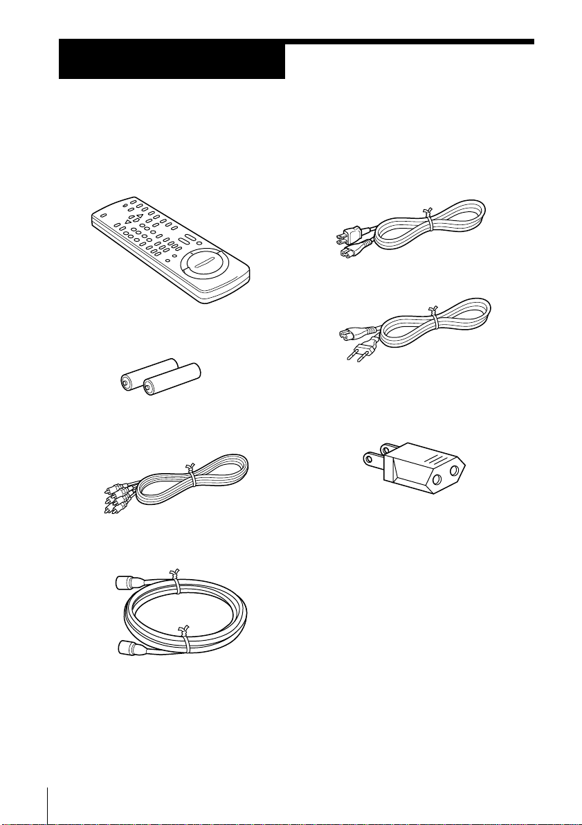
Check that you have received the following items with the VCR:
• Remote commander
• Size AA (R6) batteries
• Audio/video cable (3-phono to
3-phono)
• 75-ohm coaxial cable with F-type
connectors
• AC power cord
(SLV-760HF/761HF)
(SLV-760HF MJ/760HF PX)
• Plug adaptor (SLV-760HF MJ/
760HF PX)
If the plug supplied with your VCR does not
fit your power outlet, attach the supplied
adaptor to the plug.
Getting Started4
Step 2
Setting up the remote commander
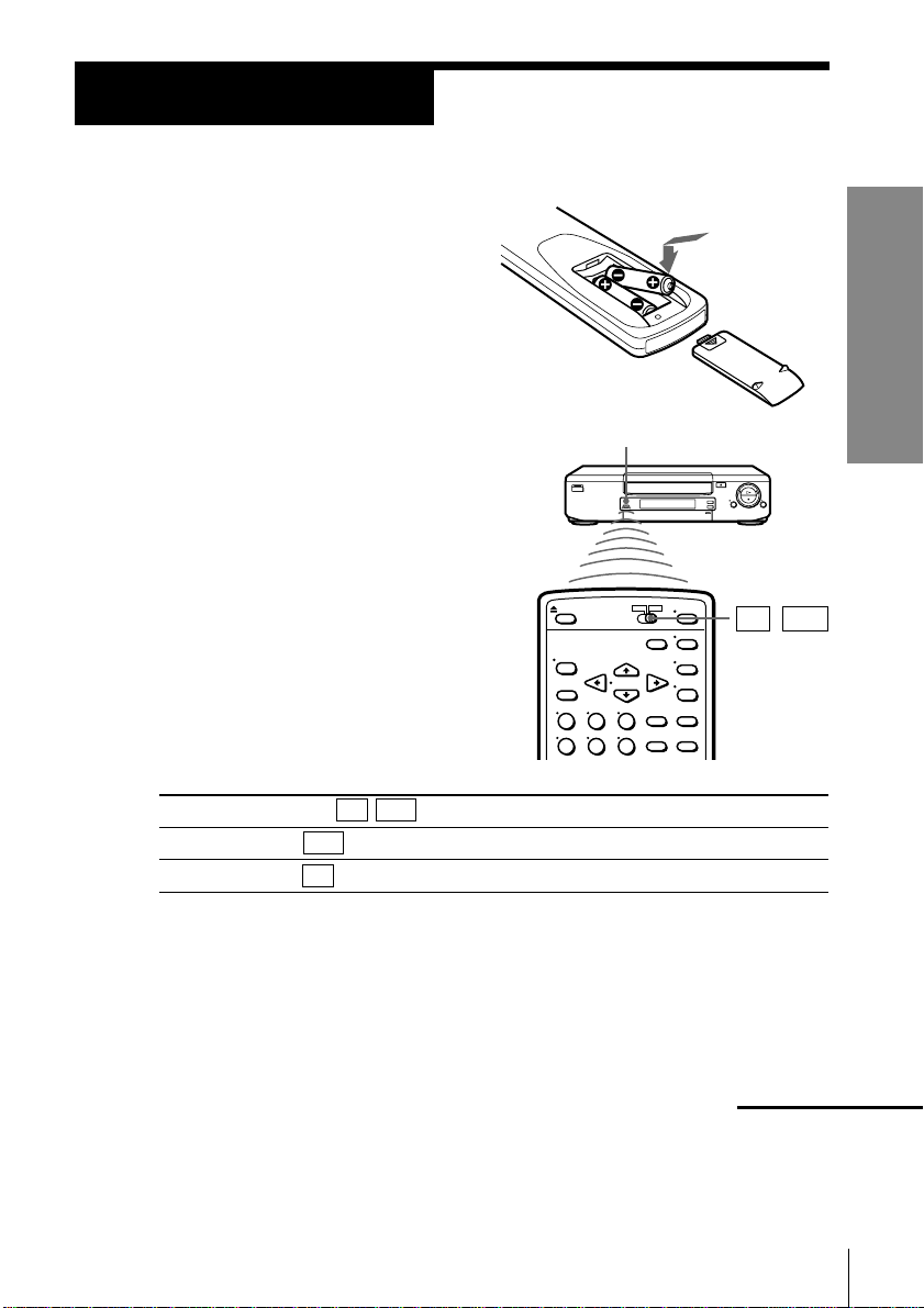
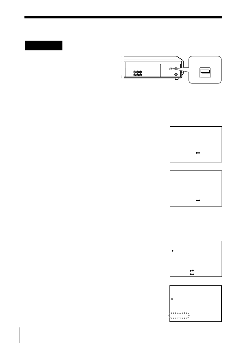
Inserting the batteries
Insert two size AA (R6) batteries by
matching the + and – on the batteries
to the diagram inside the battery
compartment.
Using the remote commander
You can use this remote
commander to operate this VCR
and a Sony TV. Buttons on the
remote commander marked with
a dot (•) can be used to operate
your Sony TV.
To operate
the VCR
a Sony TV
Set TV / VTR to
VTR and point at the remote sensor on the VCR
TV and point at the remote sensor on the TV
Getting Started
Remote sensor
TV / VTR
Notes
• With normal use, the batteries should last about three to six months.
• If you do not use the remote commander for an extended period of time, remove
the batteries to avoid possible damage from battery leakage.
• Do not use a new battery with an old one.
• Do not use different types of batteries.
continued
Getting Started
5
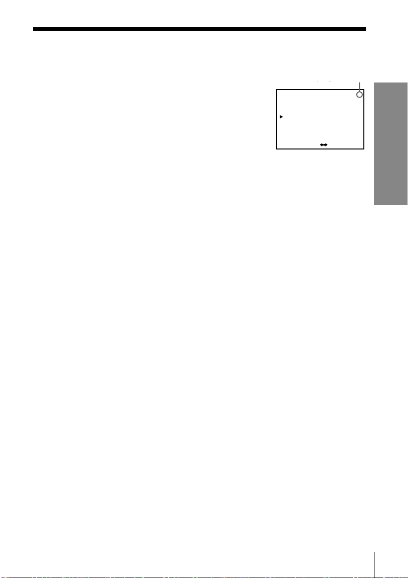
Step 2: Setting up the remote commander (continued)
Controlling other TVs with the remote commander
The remote commander is preprogrammed to control non-Sony TVs. If your
TV is listed in the table below, set the appropriate manufacturer’s code
number.
1 Set TV / VTR at the top of the remote commander to TV .
2 Hold down POWER, and enter your TV’s code number(s) using the
number buttons. Then release POWER.
Now you can use the POWER, VOL +/–, CH +/– and TV/VTR buttons to
control your TV. You can also use the buttons marked with a dot (•) to
control a Sony TV. To control the VCR, reset TV / VTR to VTR .
Code numbers of controllable TVs
If more than one code number is listed, try entering them one at a time until
you find the one that works with your TV.
Manufacturer
Sony
Akai
AOC
Centurion
Coronado
Curis-Mathes
Daytron
Fisher
General Electric
Hitachi
J.C.Penny
JVC
Notes
• If the TV uses a different remote control system from the one programmed to work
with the VCR, you cannot control your TV with the remote commander.
• If you enter a new code number, the code number previously entered will be erased.
• When you replace the batteries of the remote commander, the code number
automatically resets to 01 (Sony). Reset the appropriate code number.
Code
number
01
04
04
12
03
12
12
11
06,10
02,03
04,12
09
Manufacturer
KMC
Magnavox
Marantz
MGA/Mitsubishi
NEC
Panasonic
Philco
Philips
Pioneer
Portland
Quasar
Radio Shack
Code
number
03
03,08,12
04,13
04,12,13,17
04,12
06,19
03, 04
08
16
03
06,18
05,14
Manufacturer
RCA
Sampo
Sanyo
Scott
Sears
Sharp
Sylvania
Teknika
Toshiba
Wa rds
Yorx
Zenith
Code
number
04,10
12
11
12
07,10,11
03,05,18
08,12
03,08,14
07
03,04,12
12
15
Getting Started6
Step 3
Hookups
Selecting the best hookup option
There are many ways in which your VCR can be hooked up. To hook up
your VCR so that it works best for you, first scan through the table below.
Then use the accompanying diagrams and procedures on the following
pages to set up your VCR.
If you have
TV that has audio/video inputs
Antenna only, no cable TV
Cable box with many scrambled
channels
No cable box or cable box with only a
few scrambled channels
Cable box with onlya few scrambled
channels, using an A/B switch
After you’ve completed the connections, follow the instructions for setup.
During setup, if you need more details on the procedure described, page
numbers are provided where you can find complete, step-by-step
instructions.
After you’ve completed the setup, you’re ready to use your VCR.
Procedures differ depending on the hookup you used. For an overview,
refer to “Quick reference to using the VCR” on the back cover.
Use
Audio/video (A/V) hookup, then
follow one of the hookups below.
Hookup 1
Hookup 2
Hookup 3
Hookup 4
Getting Started
Refer to
Pages 8 to 9
Pages 10 to 12
Pages 13 to15
Pages 16 to 18
Pages 19 to 22
Before you get started
• Turn off the power to all equipment.
• Do not connect the AC power cords until all of the connections are
completed.
• Be sure you make connections firmly. Loose connections may cause
picture distortion.
• If your TV doesn’t match any of the examples provided, see your nearest
Sony dealer or qualified technician.
Getting Started
7
Step 3: Hookups (continued)
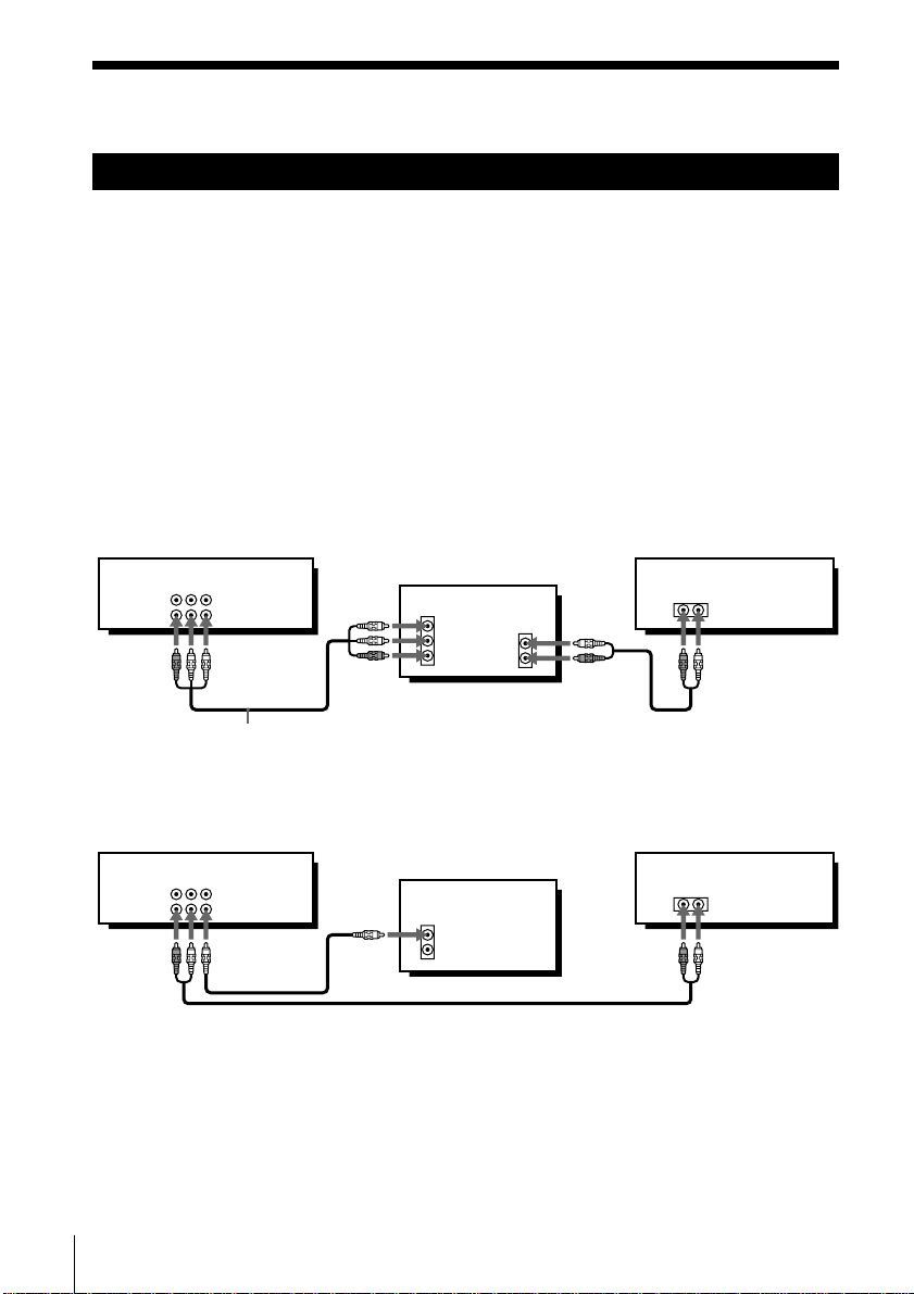
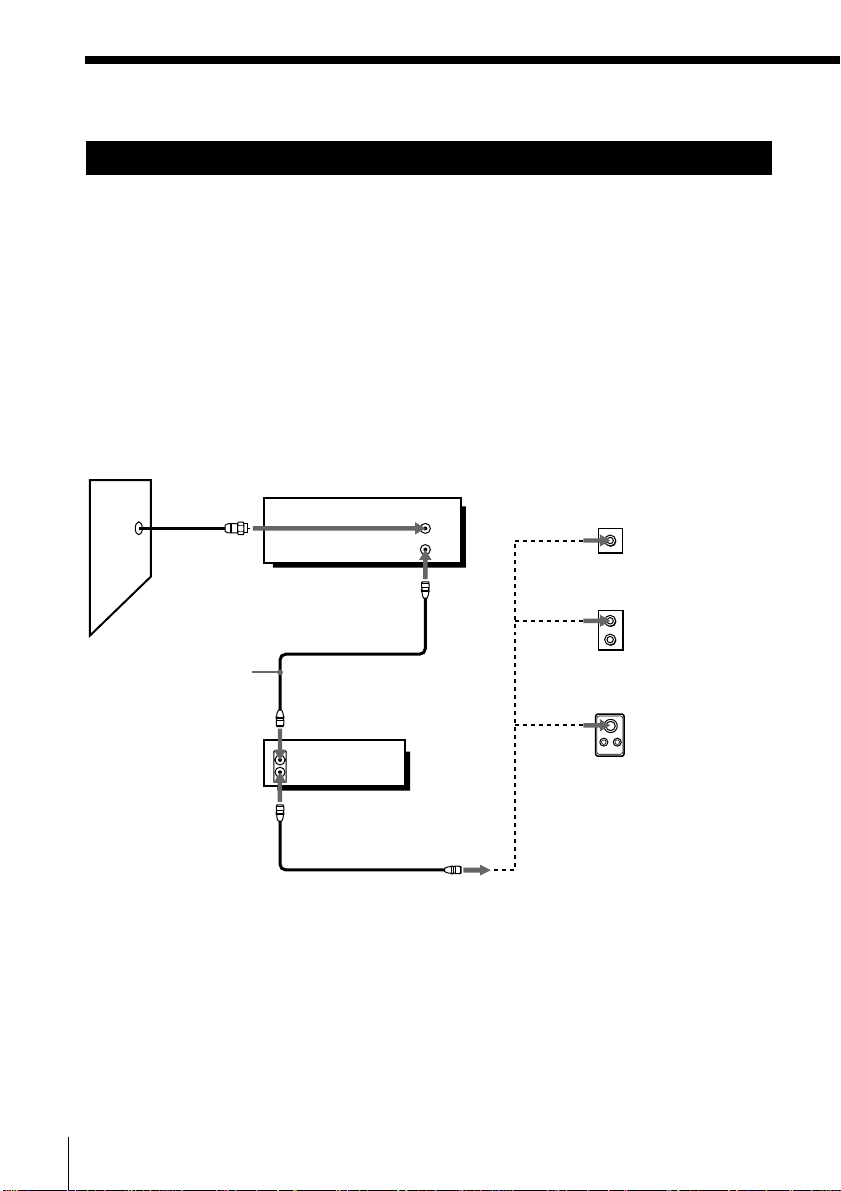
Audio/video (A/V) hookup
If your TV has audio/video (A/V) input jacks, you will get a better picture
and sound if you hook up your VCR using these connections. In addition,
for a true “home theater” experience, you should connect the audio outputs
of your VCR or TV to your stereo system. If your TV doesn’t have A/V
inputs, see the following pages for antenna or cable hookups.
If you’re not planning to use your VCR to record programs, you’re finished
setting up the VCR after you’ve made the connections shown on pages 8 and
9.
If you want to record off-air or off your cable TV system, complete these
connections first, and then go to the following pages for antenna or cable
hookups.
A Use this hookup if your TV has stereo jacks
VCR
AUDIO VIDEO
LINE-1 IN
LINE OUT
Audio/video cable (supplied)
B Use this hookup if your TV doesn’t have stereo jacks
Pages 8 to 9
Stereo receiver
TV
IN
VIDEO
AUDIO
AUDIO OUT
AUX IN
LINE-1 IN
LINE OUT
VCR
AUDIO VIDEO
TV
IN
VIDEO
AUDIO
Stereo receiver
AUX IN
Audio cable/video cable (not supplied)
Note
To play a tape in stereo, you must use the A/V connection.
Getting Started8
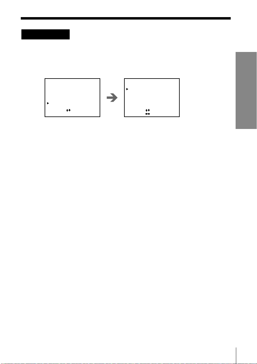
A/V hookup: VCR setup
After you’ve connected your TV and completed antenna or cable hookup,
use the following procedure to set up the VCR.
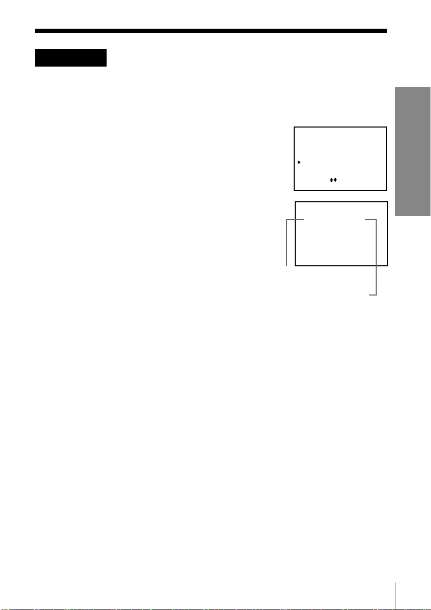
Press MENU and select
ADVANCED OPTIONS.
MENU
TIMER SET / CHECK
TUNER PRESET
CLOCK SET
SET VCR Plus+ CHANNELS
ADVANCED OPTIONS
SELECT : [ ]
SET : [ EXECUTE ]
Set AUTO ANT SEL to
OFF and press EXECUTE.
ADVANCED OPTIONS
AUTO ANT SEL
AUTO STEREO
DIMMER
AUDIO MIX
NORMAL AUDIO
APC
SELECT
SET::
[]
[]
ON
ON OFF
•
ON••
ON OFF
MAIN SAP•
ON OFF•
OFF
OFF
•
For details, see
page 53.
Caution
Connections between the VCR’s VHF/UHF connector and the antenna terminals of
the TV receiver should be made only as shown in the following instructions. Failure to
do so may result in operation that violates the regulations of the Federal
Communications Commission regarding the use and operation of RF devices. Never
connect the output of the VCR to an antenna or make simultaneous (parallel) antenna
and VCR connections at the antenna terminals of your receiver.
Note to CATV system installer
This reminder is provided to call the CATV system installer’s attention to Article 820-
40 of the NEC that provides guidelines for proper grounding and, in particular,
specifies that the cable ground shall be connected to the grounding system of the
building, as close to the point of cable entry as practical.
Getting Started
Getting Started
9
Step 3: Hookups (continued)
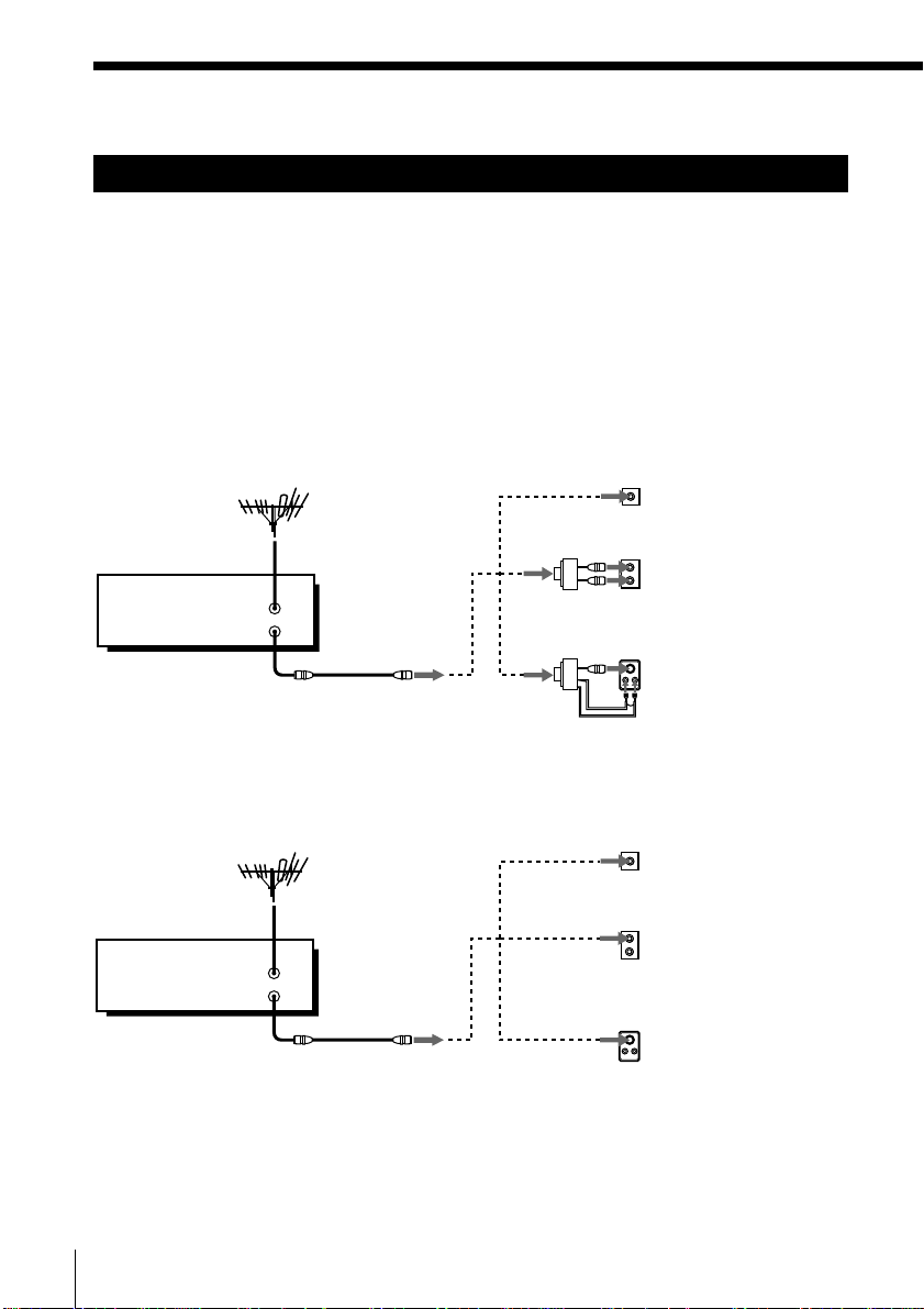
Hookup 1
Antenna hookup
Make the following connections if you’re using an antenna (if you don’t
have cable TV).
A Use this hookup if you’re using:
• VHF/UHF antenna (you get channels 2–13 and channels 14 and higher)
• UHF-only antenna (you get channels 14 and higher)
• Separate VHF and UHF antennas
VCR
B Use this hookup if you’re using a VHF-only antenna (you get
VCR
VHF/UHF
IN
OUT
channels 2–13 only)
VHF/UHF
IN
OUT
or
or
or
or
Rear of TV
VHF/UHF
A
VHF
B
UHF
VHF
C
UHF
Rear of TV
VHF/UHF
A
VHF
B
UHF
VHF
C
UHF
Pages 10 to 12
Match the type of
connector on your
TV: A, B, or C.
Match the type of
connector on your
TV: A, B, or C.
For connector types
B and C, no UHF
connection is
required.
If you cannot connect your antenna cable to the VCR directly
If your antenna cable is a flat cable (300-ohm twin lead cable), attach an external
antenna connector (not supplied) so that you can connect the cable to the VHF/UHF
IN connector. If you have separate cables for VHF and UHF antennas, you should use
a U/V band mixer (not supplied). For details, see page 57.
Getting Started10
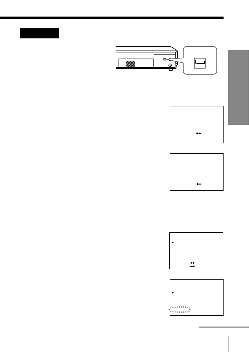
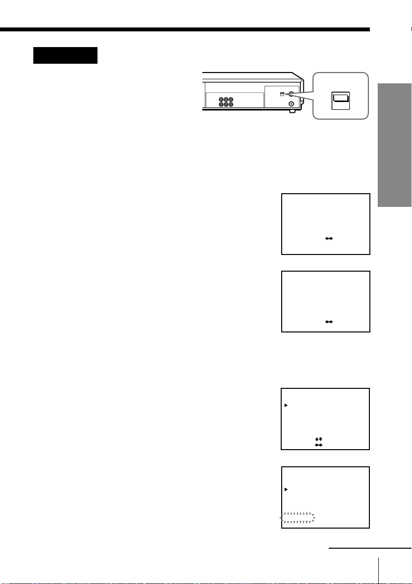
Hookup 1: VCR setup
1 Set the RF UNIT switch
to CH 3 or CH 4,
RF UNIT
whichever channel is
not used in your area. If
both are used, set the
switch to either channel.
For details, see page 56. If you made A/V connections (pages 8 and 9),
you can skip this step.
2 Set the clock. For details, see page 23.
1 Press MENU and select CLOCK SET.
2 Select AUTO, then press EXECUTE.
3 Set FULL AUTO to YES, then press EXECUTE.
CLOCK SET
AUTO•MANUAL
SELECT
SET
QUIT
AUTO CLOCK SET
FULL•AUTO YES
SET
END
3 Preset the channels into the VCR. For details,
see page 29.
1 Press MENU and select TUNER PRESET.
CH3
CH4
:[ ]
:[ ]
EXECUTE
:[ ]
MENU
[]:
[]: EXECUTE
Getting Started
NO
2 Set ANTENNA/CABLE to ANT.
3 Select AUTO PRESET and press EXECUTE.
TUNER PRESET
ANTENNA / CABLE
AUTO PRESET
MANUAL SET
AFT
FINE TUNING
SELECT
[]
[]
SET::
TUNER PRESET
ANTENNA / CABLE
AUTO PRESET
MANUAL SET
AFT
FINE TUNING
Please wait
Getting Started
CH1
CABLE
ANT
ADD
•
ERASE
ON••
OFF
CH1
CABLE
ANT
ADD
•
ERASE
ON••
OFF
continued
11
Step 3: Hookups (continued)
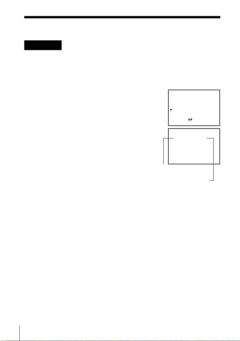
Hookup 1: VCR Plus+ channel setup
1 Find the VCR Plus+ Channel Listing in your program guide. For
details, see page 33.
2 If the channels in the program guide are different from the channels
that you actually use on your TV, set the channels that are different as
follows. For details, see page 34.
1 Press MENU and select SET VCR Plus+
CHANNELS.
2 Enter the program guide channel, then the
channel you use on your TV.
3 Press EXECUTE.
MENU
TIMER SET / CHECK
TUNER PRESET
CLOCK SET
SET VCR Plus+ CHANNELS
ADVANCED OPTIONS
SELECT : [ ]
SET : [ EXECUTE ]
SET VCR Plus+ CHANNELS
GUIDE
CH TV CH
25 – 15
Push [0–9] keys to set
program GUIDE CH
Or, push [ EXECUTE ] to see
VCR Plus+ CHANNEL LIST
Program guide channel
Your actual TV channel
Automatic clock setting
If you select AUTO in the CLOCK SET menu, then set FULL AUTO to YES, it
automatically sets the clock the first time you turn off the VCR. After that,
whenever you turn off the VCR, it checks the time and adjusts the clock,
even for Daylight Saving Time. The VCR sets the clock by picking up a time
signal provided by some TV channels.
If you want to use the timer to record right away, or if the channels in your
area do not carry time signals, set the clock manually. For details, see pages
27 and 28.
Getting Started12
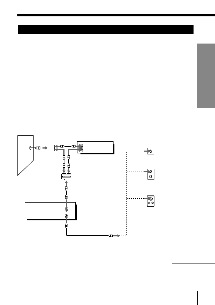
Hookup 2
Hookup 4
Hookup 4
Cable box with many scrambled channels
Recommended use
Use this hookup if your cable system scrambles all or most channels.
What you can do with this hookup
• Record any channel by selecting the channel on the cable box
What you can’t do
• Record with the cable box off
• Record one channel while watching another channel
Pages 13 to 15
Pages 19 to 21
Pages 19 to 21
Getting Started
Wall
VCR
Cable box
IN
OUT
VHF/UHF
IN
OUT
Rear of TV
VHF/UHF
or
VHF
UHF
or
VHF
UHF
Match the type of
A
connector on your TV:
A, B, or C.
For connector types B
B
and C, no UHF
connection is required.
C
continued
Getting Started
13

Step 3: Hookups (continued)
Hookup 2: VCR setup
1 Set the RF UNIT switch to
CH 3 or CH 4, whichever
channel is not used in
your area. If both are
used, set the switch to
either channel.
For details, see page 56. If you made A/V connections (pages 8 and 9),
you can skip this step.
2 Turn on your cable box.
3 Set the clock. For details, see page 23.
1 Press MENU and select CLOCK SET.
2 Select AUTO, then press EXECUTE.
3 Set FULL AUTO to YES, then press EXECUTE.
CLOCK SET
AUTO•MANUAL
SELECT
SET
QUIT
AUTO CLOCK SET
FULL•AUTO YES
SET
END
4 Preset the channels into the VCR. For details, see page 29.
1 Press MENU and select TUNER PRESET.
RF UNIT
CH3
CH4
:[ ]
:[ ]
EXECUTE
:[ ]
MENU
[]:
[]: EXECUTE
NO
2 Set ANTENNA/CABLE to CABLE.
3 Select AUTO PRESET and press EXECUTE.
TUNER PRESET
ANTENNA / CABLE
AUTO PRESET
MANUAL SET
AFT
FINE TUNING
SELECT
[]
[]
SET::
TUNER PRESET
ANTENNA / CABLE
AUTO PRESET
MANUAL SET
AFT
FINE TUNING
Please wait
CH1
ANT
CABLEON•
ADD
•
ERASE
OFF
•
CH1
CABLEON•
ANT
ADD
•
ERASE
•
OFF
Getting Started14
Hookup 2: VCR Plus+ channel setup
1 Find the VCR Plus+ Channel Listing in your program guide. For
details, see page 33.
2 Enter all the channels you want to record and the cable box output
channel (usually 2, 3, or 4). For details, see page 34.
1 Press MENU and select SET VCR Plus+
CHANNELS.
MENU
TIMER SET / CHECK
TUNER PRESET
CLOCK SET
SET VCR Plus+ CHANNELS
ADVANCED OPTIONS
SELECT : [ ]
SET : [ EXECUTE ]
Getting Started
2 Enter the program guide channel, then the cable
box output channel.
3 Press EXECUTE.
SET VCR Plus+ CHANNELS
GUIDE
CH TV CH
33 – 5
Push [0–9] keys to set
program GUIDE CH
Or, push [ EXECUTE ] to see
VCR Plus+ CHANNEL LIST
Program guide channel
Cable box output channel
Automatic clock setting
To use the Auto Clock Set feature with this hookup, you need to manually
select a channel that carries a time signal:
1 Tune the cable box to a channel that carries a time signal.
2 Select AUTO in the CLOCK SET menu to turn on the Auto Clock Set
feature.
3 Turn off the VCR. It automatically sets the clock and adjusts for
Daylight Saving Time by picking up the time signal.
If you want to use the timer to record right away, or if the channels in your
area do not carry time signals, set the clock manually. For details, see pages
27 and 28.
Note
To use the automatic clock setting feature, leave the cable box on.
Getting Started
15
Step 3: Hookups (continued)
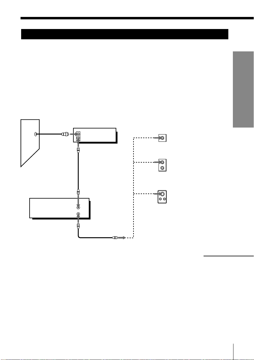
Hookup 3
No cable box, or
cable box with only a few scrambled channels
Recommended use
Use this hookup if you do not have a cable box. Also use this hookup if your
cable system scrambles only a few channels.
What you can do with this hookup
• Record any unscrambled channel by selecting the channel on the VCR
What you can’t do
• Record scrambled channels that require a cable box
Wall
Connect this cable
directly to your TV if
you don't have a
cable box.
Cable box
IN
OUT
VCR
VHF/UHF
IN
OUT
Rear of TV
VHF/UHF
or
or
Pages 16 to 18
A Match the type
of connector
on your TV: A,
B, or C.
VHF
B
For connector
types B and C, no
UHF connection
UHF
is required.
VHF
C
UHF
Getting Started16
Hookup 3: VCR setup
1 Set the RF UNIT switch
to CH 3 or CH 4,
whichever channel is not
used in your area. If both
are used, set the switch to
either channel.
For details, see page 56. If you made A/V connections (pages 8 and 9),
you can skip this step.
2 Turn on your cable box.
3 Set the clock. For details, see page 23.
1 Press MENU and select CLOCK SET.
2 Select AUTO, then press EXECUTE.
3 Set FULL AUTO to YES, then press EXECUTE.
CLOCK SET
AUTO•MANUAL
SELECT
SET
QUIT
AUTO CLOCK SET
FULL•AUTO YES
SET
END
4 Preset the channels into the VCR. For details, see page 29.
1 Press MENU and select TUNER PRESET.
RF UNIT
CH3
CH4
:[ ]
:[ ]
EXECUTE
:[ ]
MENU
[]:
[]: EXECUTE
Getting Started
NO
2 Set ANTENNA/CABLE to CABLE.
3 Select AUTO PRESET and press EXECUTE.
TUNER PRESET
ANTENNA / CABLE
AUTO PRESET
MANUAL SET
AFT
FINE TUNING
SELECT
[]
SET::
[]
TUNER PRESET
ANTENNA / CABLE
AUTO PRESET
MANUAL SET
AFT
FINE TUNING
Please wait
Getting Started
CH1
CABLEON•
ANT
ADD
•
ERASE
•
OFF
CH1
CABLEON•
ANT
ADD
•
ERASE
•
OFF
continued
17

Step 3: Hookups (continued)
Hookup 3: VCR Plus+ channel setup
1 Find the VCR Plus+ Channel Listing in your program guide. For
details, see page 33.
2 If the channels in the program guide are different from the channels
that you actually use on your TV, set the channels that are different as
follows. For details, see page 34.
1 Press MENU and select SET VCR Plus+
CHANNELS.
MENU
TIMER SET / CHECK
TUNER PRESET
CLOCK SET
SET VCR Plus+ CHANNELS
ADVANCED OPTIONS
SELECT : [ ]
SET : [ EXECUTE ]
2 Enter the program guide channel, then the
channel you use on your TV.
3 Press EXECUTE.
SET VCR Plus+ CHANNELS
GUIDE
CH TV CH
25 – 15
Push [0–9] keys to set
program GUIDE CH
Or, push [ EXECUTE ] to see
VCR Plus+ CHANNEL LIST
Program guide channel
Your actual TV channel
Automatic clock setting
If you select AUTO in the CLOCK SET menu, then set FULL AUTO to YES, it
automatically sets the clock the first time you turn off the VCR. After that,
whenever you turn off the VCR, it checks the time and adjusts the clock,
even for Daylight Saving Time. The VCR sets the clock by picking up a time
signal provided by some TV channels.
If you want to use the timer to record right away, or if the channels in your
area do not carry time signals, set the clock manually. For details, see pages
27 and 28.
Getting Started18
Hookup 4
Cable box with only a few scrambled channels, using
an A/B switch
Pages 19 to 22
Wall
Recommended use
By using an A/B switch (not supplied), this hookup allows you to record
both scrambled and unscrambled channels conveniently.
What you can do with this hookup
• Record any unscrambled channel by selecting the channel directly on the
VCR (the A/B switch is set to A)
• Record any scrambled channel by selecting the channel on the cable box
(the A/B switch is set to B)
What you can’t do
• Record one scrambled channel while watching another channel (the A/B
switch is set to B)
Splitter
A/B switch
VCR
Cable box
IN
OUT
A
VHF/UHF
IN
OUT
B
Rear of TV
VHF/UHF
or
UHF
or
VHF
UHF
A
Match the type
of connector on
your TV: A, B,
or C.
VHF
For connector
B
types B and C,
no UHF
connection is
required.
C
Getting Started
continued
Getting Started
19
Step 3: Hookups (continued)
Hookup 4: VCR setup
1 Set the RF UNIT switch to
CH 3 or CH 4, whichever
channel is not used in
your area. If both are
used, set the switch to
either channel.
For details, see page 56. If you made A/V connections (pages 8 and 9),
you can skip this step.
2 Set the A/B switch to “A.”
3 Set the clock. For details, see page 23.
1 Press MENU and select CLOCK SET.
2 Select AUTO, then press EXECUTE.
3 Set FULL AUTO to YES, then press EXECUTE.
CLOCK SET
AUTO•MANUAL
SELECT
SET
QUIT
AUTO CLOCK SET
FULL•AUTO YES
SET
END
4 Preset the channels into the VCR. For details, see page 29.
1 Press MENU and select TUNER PRESET.
RF UNIT
CH3
CH4
:[ ]
:[ ]
EXECUTE
:[ ]
MENU
[]:
[]: EXECUTE
NO
2 Set ANTENNA/CABLE to CABLE.
3 Select AUTO PRESET and press EXECUTE.
TUNER PRESET
ANTENNA / CABLE
AUTO PRESET
MANUAL SET
AFT
FINE TUNING
SELECT
[]
[]
SET::
TUNER PRESET
ANTENNA / CABLE
AUTO PRESET
MANUAL SET
AFT
FINE TUNING
Please wait
CH1
ANT
CABLEON•
ADD
•
ERASE
OFF
•
CH1
CABLEON•
ANT
ADD
•
ERASE
•
OFF
Getting Started20
5 Preset the cable box output channel (usually 2, 3 or 4). For details, see
03
page 31.
1 Press MENU and select TUNER PRESET.
2 Enter the cable box output channel.
3 Set MANUAL SET to ADD and press
EXECUTE.
Cable box output channel
TUNER PRESET
ANTENNA / CABLE
AUTO PRESET
MANUAL SET
AFT
FINE TUNING
SELECT CH
ADD / ERASE::[ ]
CABLEON•
ANT
ADD
•
ERASE
•
OFF
[ 0–9 ] , [ ENTER ]
CH3
Getting Started
Getting Started
21
 Loading...