

SONY SLV-D350P, SLV-550P SERVICE MANUAL
http://servis-manual.com/

2-4 VCR DECK
2-4-1 Holder FL Cassette Ass’y Removal
1) Pull the Holder FL Cassette Ass’y 1 to the eject position.
2) Pull the Holder FL Cassette Ass’y 1 as grasping the Holder FL
Cassette Ass’y 1 and Lever FL Cassette-R 2 in the same time to
release hooking from Main Base until the Boss [A] of Holder FL
Cassette Ass’y 1 is taken out from the Rail [B].
3) Lift the Holder FL Cassette Ass’y 1, in this time, you have to
grasp the Lever FL Cassette-R 2 Continuously until the Holder
FL Cassette Ass’y 1 is taken out completely.
Note: Be sure to insert Lever FL Cassette-R 2 in the direction of
“A” to prevent separation and breakage of the Lever FL CassetteR 2 at disassembling and reassembling.
1 HOLDER FL
CASSETTEE ASS'Y
BOSS [A]
"A"
2 LEVER FL CASSETTEE -R
RAIL [B]
2-4-2 Lever FL Arm Ass’y Removal
1) Push the hole “ A” in the direction of arrow “B” use the pin.(about
Dia. 2.5)
2) Pull out the Lever FL Arm Ass’y 1 from the Boss of Main Base.
3) Remove the Lever FL Arm Ass’y 1 in the direction of arrow “C”.
HOLE "A"
PIN
"B"
"C"
1 LEVER FL ARM ASS'Y
Fig. 2-12 Lever FL Arm Ass’y Removal
Fig. 2-11 Holder FL Cassette Ass’y Removal
2-7

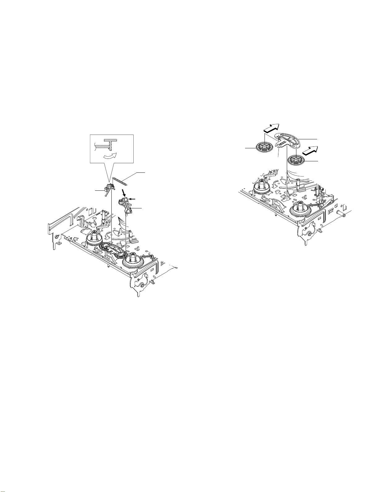
2-4-3 Lever FL Door Removal
2-4-4 Slider FL Drive, Gear FL Cam Removal
1) Release the Hook 2 and Remove the Lever FL Door 1 in the
direction of arrow “A”.
2 LEVER FL DOOR
"A"
"B"
1 SLIDER FL DRIVE
"C"
Fig. 2-13 Lever FL Door Removal
1) Pull the Slider FL Drive 1 to the front direction.
2) Remove the Slider FL Driv e 1 in the direction of arrow . (Refer to
Fig. 2-14)
3) Remove the Gear FL cam 2.
Note: When reinstalling be sure to reassemble Slider FL drive 1
after you insert the Boss of Lever FL ARM-R in Groove of Slider FL
drive 1.
Assembly: Align the Gear FL Cam 1 with the Gear worm wheel
Post as shown drawing.
(Refer to Timing point)
Fig. 2-14 Slider FL Drive Removal
1 GEAR FL CAM
POST
TIMING POINT
Fig. 2-15 Gear FL Cam, Gear Worm
2 GEAR FL CAM
1 SLIDER FL DRIVE
GEAR WORM WHEEL
2-8
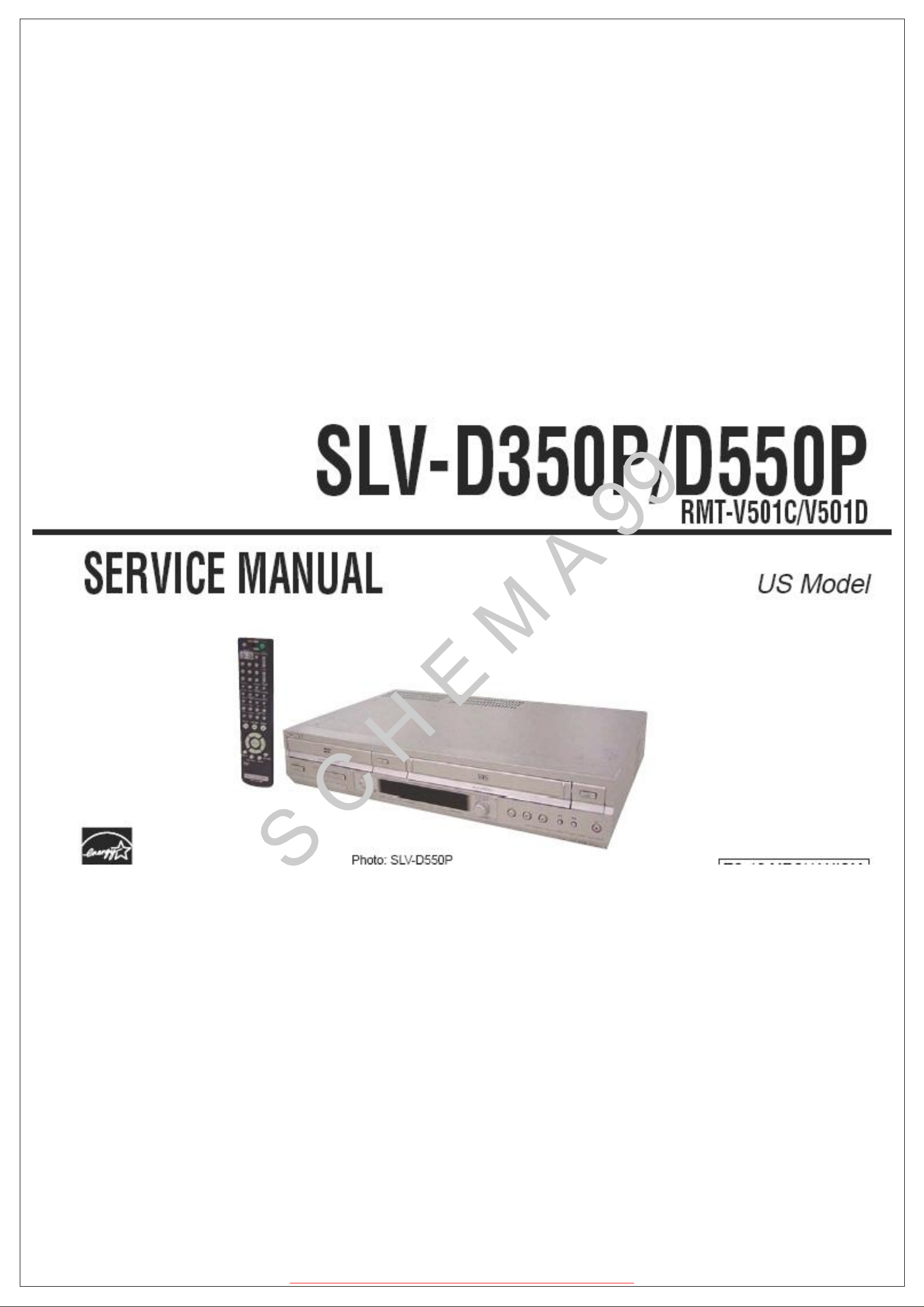
2-4-5 Gear Worm Wheel Removal
2-4-6 Cable Flat Removal
1) Remove the Gear Worm wheel 1.
Fig. 2-16 Gear Worm Wheel Removal
1 GEAR WORM WHEEL
1) Remove the Drum connecting part of Cable Flat 1 fr om Connector
Waffer 2.
2 CONNECTOR WAFER
Fig. 2-17 Cable Flat Removal
1 CABLE FLAT
2-9
1 SCREW
2 BRAKET GEAR
4 GEAR JOINT 1
3 GEAR JOINT 2
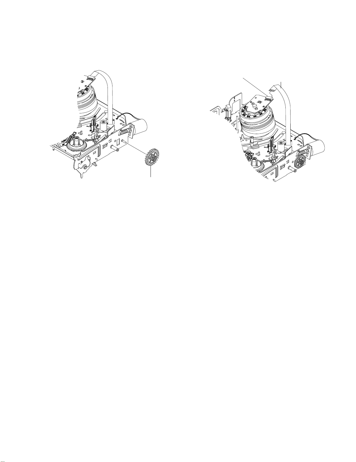
2-4-7 Motor Loading Ass’y Removal
2-4-8 Bracket Gear, Gear Joint 2, 1 Removal
1) Remove the screw 1.
2) Remove the Motor Loading Ass’y 2.
1 SCREW
Fig.2-18 Motor Loading Ass’y Removal
1) Remove the SCREW 1.
2) Remove the Bracket Gear 2.
3) Remove the Gear Joint 2 3.
4) Remove the Gear Joint 1 4.
Assembly:
1) Be sure to align dot mark of Gear Joint 1 1 with dot mark of
Gear Joint 2 2 as shown Fig 2-20.
(Refer to Timing point1)
2) Confirm the Timing Point 2 of the Gear Joint 2 2 and Slider
Cam 3.
2 MOTOR LOADING ASS`Y
Fig. 2-19 Bracket Gear, Gear Joint 1,2 Removal
1 GEAR JOINT1
TIMING POINT 1
2 GEAR JOINT2
3 SLIDER CAM
TIMING POINT 2
Fig. 2-20 Gear Joint 1,2 Assembly
2-10
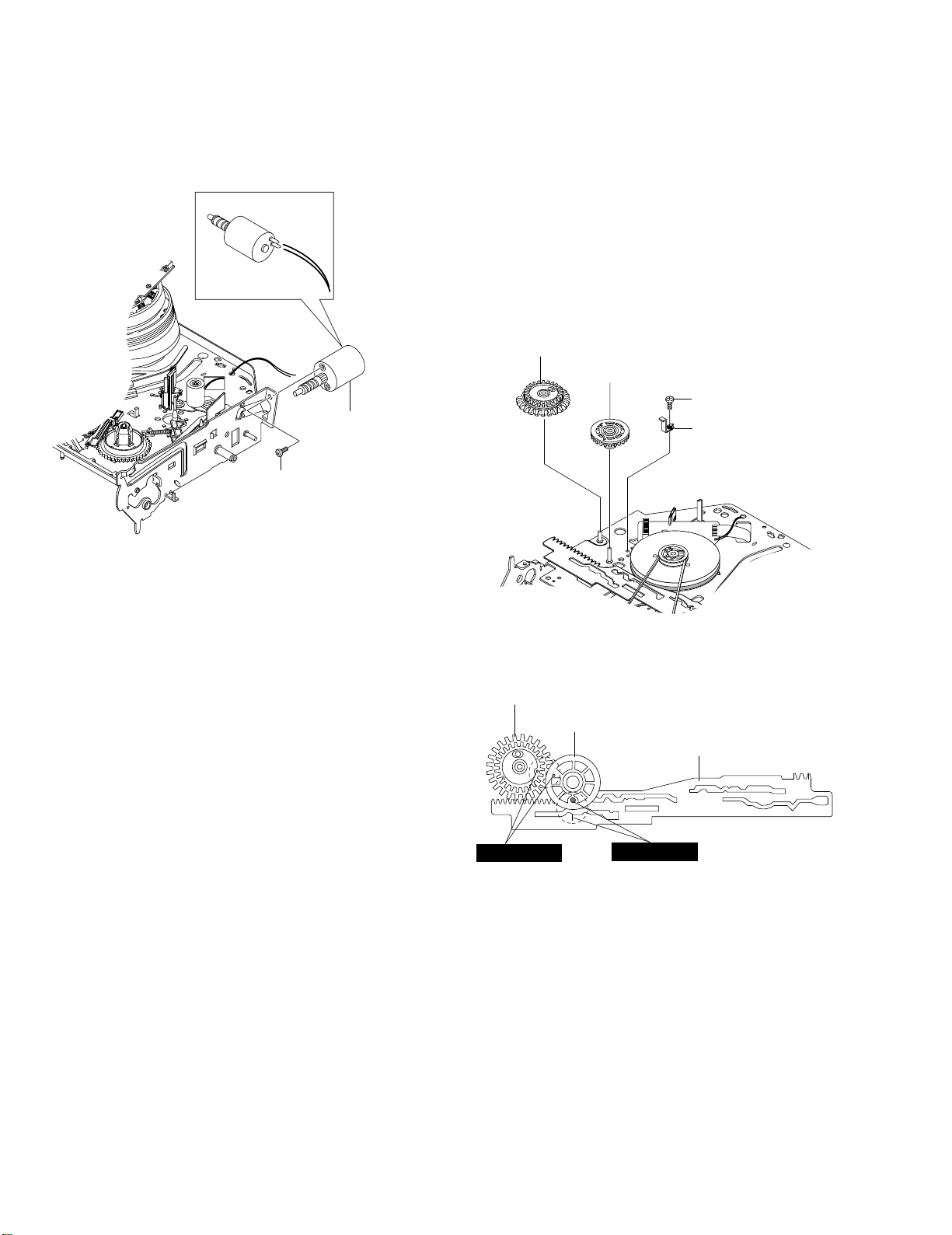
2-4-9 Gear Loading Drive, Slider Cam,
2 LEVER LOAD S
1 LEVER LOAD T
PIN A
PIN C
PIN B
PIN D
3 SLIDER CAM
TIMING POINT 2
TIMING POINT 1
TIMING POINT 3
Lever Load S, T Ass’y Removal
2-4-10 Gear Loading Drive, Slider Cam,
Lever Load S, T Ass’y Assembly
1) Remove the Belt Pulley. (Refer to Fig. 2-38)
2) Remove the Gear Loading Drive 1 after releasing Hook [A] in
the direction arrow as shown in detail drawing.
3) Remove the Slider Cam 2.
4) Remove the Lever Load S Ass’y 3 & Lever Load T Ass’y 4.
HOOK(A)
2 SLIDE CAM
1 GEAR LOADING DRIVE
4 LEVER LOAD T ASS'Y
3 LEVER LOAD S ASS'Y
1) When reinstalling, be sure to align dot of Lever Load T Ass’y 1
with dot of Lever Load S Ass’y 2 as shown in drawing, (Refer to
Timing Point 1).
2) Insert the Pin A,B,C,D into the Slider Cam 3 hole,
3) Be sure to align dot of Lever Load T 1 and dot of Gear Loading
Drive 4, (Refer to Timing Point 2).
4) Aline dot of Gear Loading drive 4 with mark of Slider Cam 3 as
shown in drawing (Refer to Timing Point 3).
Fig. 2-21 Gear Loading Drive, Slider Cam,
Lever T, S Load Ass’y Removal
Fig. 2-22 Gear Loading Drive, Slider Cam,
Lever Load S, T Ass’y Assembly
2-11

1 SPRING TENTION LEVER
2 LEVER TENTION ASS`Y
3 BAND BRAKE ASS`Y
STOPPER
MARK[B]
"A"
2-4-11 Lever Pinch Drive,
Lever Tension Drive Removal
2-4-12 Lever Tension Ass’y,
Band Brake Ass’y Removal
1) Remove the Lever Pinch Drive 1, Lever Tension Drive 2.
1 LEVER PINCH DRIVE
2 LEVER TENSION DRIVE
Fig. 2-23 Lever Pinch Drive,
Lever Tension Drive Removal
1) Remove the Lever Brake S Ass’y (Refer to Fig 2-25).
2) Remove the Spring Tension Lever 1.
3) Rotate stopper of Main Base in the direction of arrow “A”.
4) Lift the Lever Tension Ass’y 2 & Band brake Ass’y 3.
Note:
1) When replacing the Lever T ension Ass’y 2, be sure to apply Grease
on the post,
2) Take care not to touch stain on the felt side, and not to be folder
and broken Band brake Ass’y
3) After Lever Tension Ass’y seated, Rotate stopper of Main Base to
the Mark[B].
Fig. 2-24 Lever Tension Ass’y,
Band Brake Ass’y Removal
2-12
2-4-13 Lever Brake S, T Ass’y Removal
2-4-14 Gear Idle Ass’y Removal
1) Release the Hook [A] and the Hook [B], [C] in the direction of
arrow as shown in Fig 2-25.
2) Lift the Lever S, T Brake Ass’y 1, 2 with spring brake 3.
Assembly:
1) Assembly the Lever S Brake Ass’y 1 on the Main Base.
2) Assembly the Lever T Brake Ass’y 2 with spring brake 3.
Note: Take extreme care not to be folded and
transformed Spring Brake at removing or reinstalling.
HOOK(A)
3 SPRING BRAKE
1 LEVER S BRAKE ASS'Y
HOOK(C)
HOOK(B)
2 LEVER T BRAKE ASS`Y
1) Push the Lever Idle 1 in the direction of arrow “A”, “B”.
2) Lift the Lever Idle 1.
Assembly:
1) Apply oil in two Bosses of Lever Idle 1.
2) Assemble the Gear Idle 2 with the Lever Idle 1.
Note: When replacing the Gear Idle 2, be sure to add oil in the boss
of Lever Idle 1.
"A"
1 LEVER IDLE
2 GEAR IDLE
HOOK "C"
"B"
2 GEAR IDLE
Fig. 2-25 Lever Brake S, T Ass’y Removal
Fig. 2-26 Gear Idle Ass’y Removal
2-13
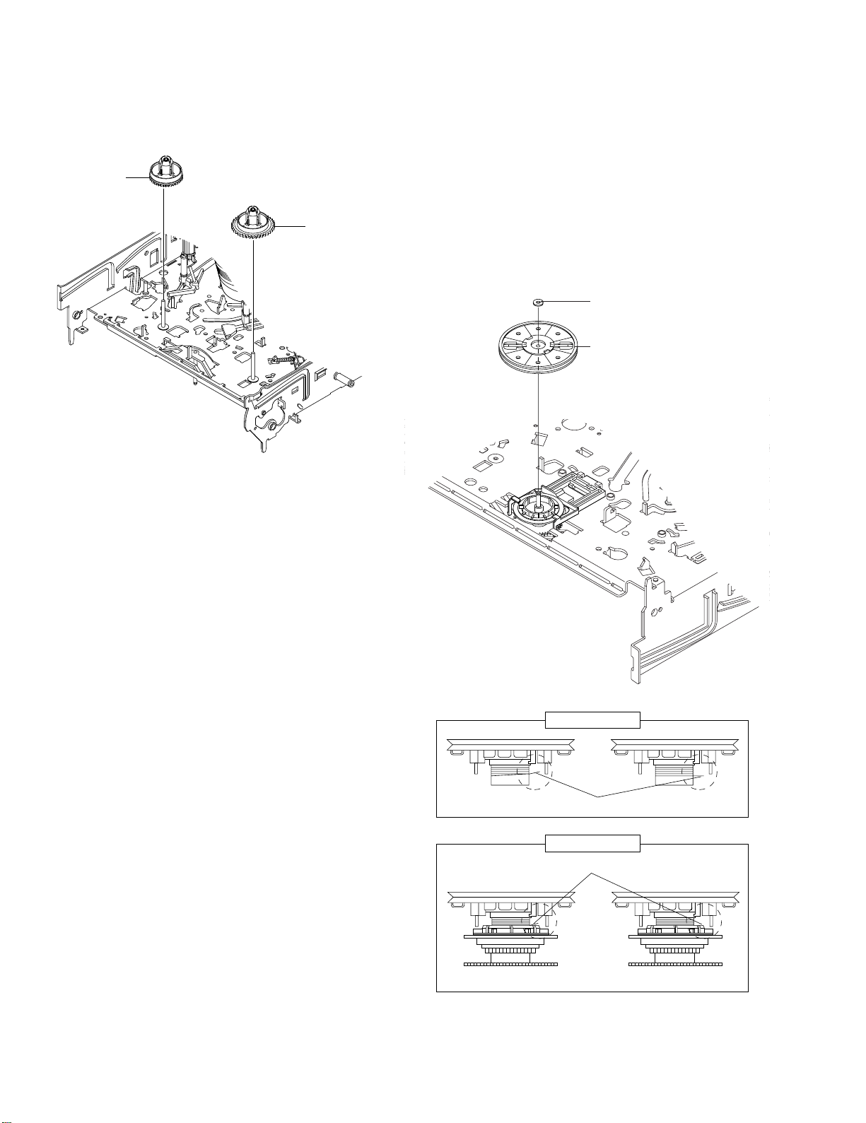
2-4-15 Disk S, T Reel Removal
2-4-16 Holder Clutch Ass’y Removal
1) Lift the Disk S, T Reel 1, 2.
1 DISK S REEL
Fig. 2-27 Disk S, T Reel Removal
2 DISK T REEL
1) Remove the Washer Slit 1.
2) Lift the Holder Clutch Ass’y 2.
Note: When you reinstall Holder Clutch Ass’y
1) Check the condition of spring as shown in detail A.
2) Don't push Holder Clutch Ass’y down with excessive force Just
insert Holder Clutch Ass’y into post center with dead force and
Rotate it smoothly.
Be sure to confirm that spring is in the slit of Gear Center Ass’y as
shown in detail B.
1 WASHER SLIT
2 HOLDER CLUTCH ASS`Y
2-14
DETAIL A
<BAD> SPRING <GOOD>
DETAIL B
SPRING
<BAD>
Fig. 2-28 Holder Clutch Ass’y Removal
<GOOD>
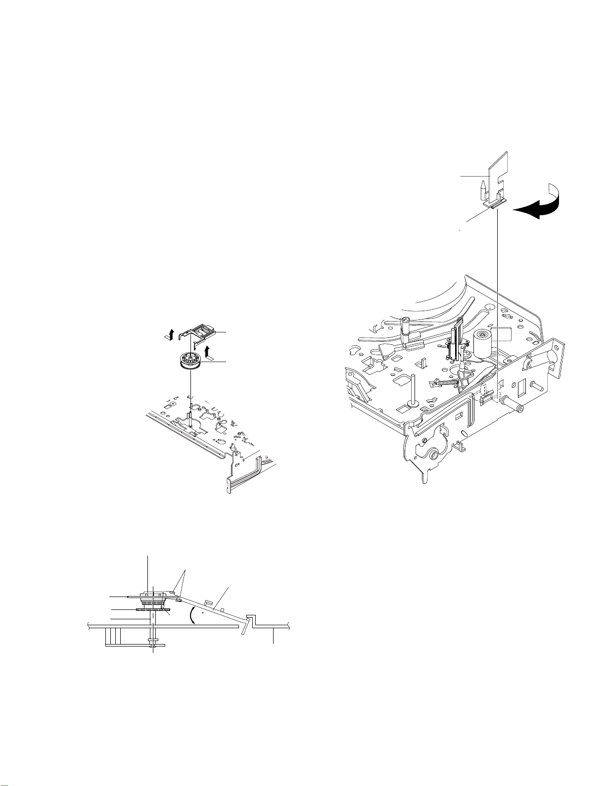
2-4-17 Lever Up Down Ass’y, Gear Center
Ass’y Removal
1) Remove the 2 hooks in the direction of arrow as shown Fig. 2-29
and lift the Lever Up Down Ass’y 1.
2) Lift the Gear Center Ass’y 2.
Assembly:
1) Insert the Lever Up Down Ass’y 1 in the rectangular holes on
Main Base as shown in Fig 2-30.
2) Lift the Lever Up Down Ass’y 1 about 35°.
(Refer to Fig 2-30)
3) Insert Ring of the Gear Center Ass’y 2 in the Guide of the Lever
Up Down Ass’y 1.
4) Insert the Gear Center Ass’y 2 in the post on Main Base.
5) Push down the Lever Up Do wn Ass’y 1 for locking of the Hook.
Note:
1) Take care not to separate and sentence does not mark sense.
2) Be sure to confirm that Ring of the Gear Center Ass’y 2 is in the
Guide of the Lever Up Down Ass’y 1 after finishing assembly of
Lever Up Down Ass’y 1 and Gear Center Ass’y 2.
1 LEVER UP DOWN ASS`Y
2-4-18 Guide Cassette Door Removal
1) Lift the Hook [A].
2) Rotate the Guide Cassette Door 1 in the direction of arrow.
Note: After reinstalling the Guide Cassette Door 1 sure the Hook
[A].
1 GUIDE CASSETTE DOOR
HOOK [A]
GEAR CENTER ASS'Y
RING
GEAR
POST
2 GEAR CENTER ASS`Y
Fig. 2-29 Lever Up Down Ass’y Removal
GUIDE
LEVER UP DOWN ASS'Y
35
HOOK
Fig. 2-31 Guide Cassette Door Removal
Fig. 2-30 Lever Up Down Ass’y Removal
MAIN BASE
2-15
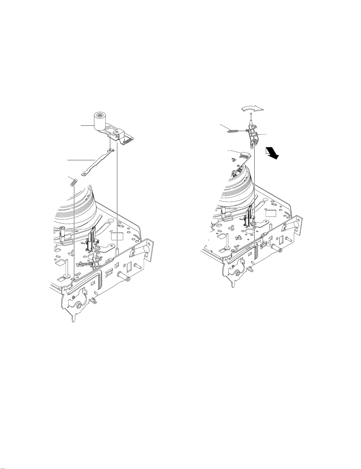
2-4-19 Lever Unit Pinch Ass’y, Plate Joint,
Spring Pinch Drive Removal
1) Lift the Unit Pinch Ass’y 1.
2) Remove the Plate Joint 2 from Lever Pinch Drive.
3) Remove the Spring Pinch Drive 3.
Note:
1) Take extreme care not to touch the grease on the Roller Pinch.
2) When reinstalling, be sure to apply grease on the post pinch roller.
2-4-20 Lever #9 Guide Ass’y Removal
1) Remove the Spring #9 Guide 1.
2) Lift the Spring #9 Guide Ass’y 2 in the direction of arrow “A”.
Note:
1) Take extreme care not to get grease on the tape Guide Post.
2) After reinstalling, check the bottom side of the Post #9 Guide to
the top side of Main Base.
"A"
1 LEVER UNIT PINCH ASS`Y
2 PLATE JOINT
3 SPRING PINCH DRIVE
1 SPRING #9 GUIDE
2 LEVER #9 GUIDE ASS`Y
"B"
Fig. 2-32 Lever Unit Pinch Ass’y, Plate Joint,
Spring Pinch Drive Removal
Fig. 2-33 Lever #9 Guide Ass’y Removal
2-16

2-4-21 FE Head Removal
2-4-22 ACE Head Removal
1) Remove the screw 1.
2) Lift the FE Head 2.
1 FE HEAD
1) Pull out the FPC from connector of ACE Head Ass’y 2.
2) Remove the screw 1.
3) Lift the ACE Head Ass’y 2.
1 SCREW
2 HEAD ACE ASS`Y
Fig. 2-34 FE Head Removal
Fig. 2-35 ACE Head Removal
2-17
 Loading...