

Sony SLV-380, SLV-441, SLV-440, SLV-340, RMT-V154 Service Manual
...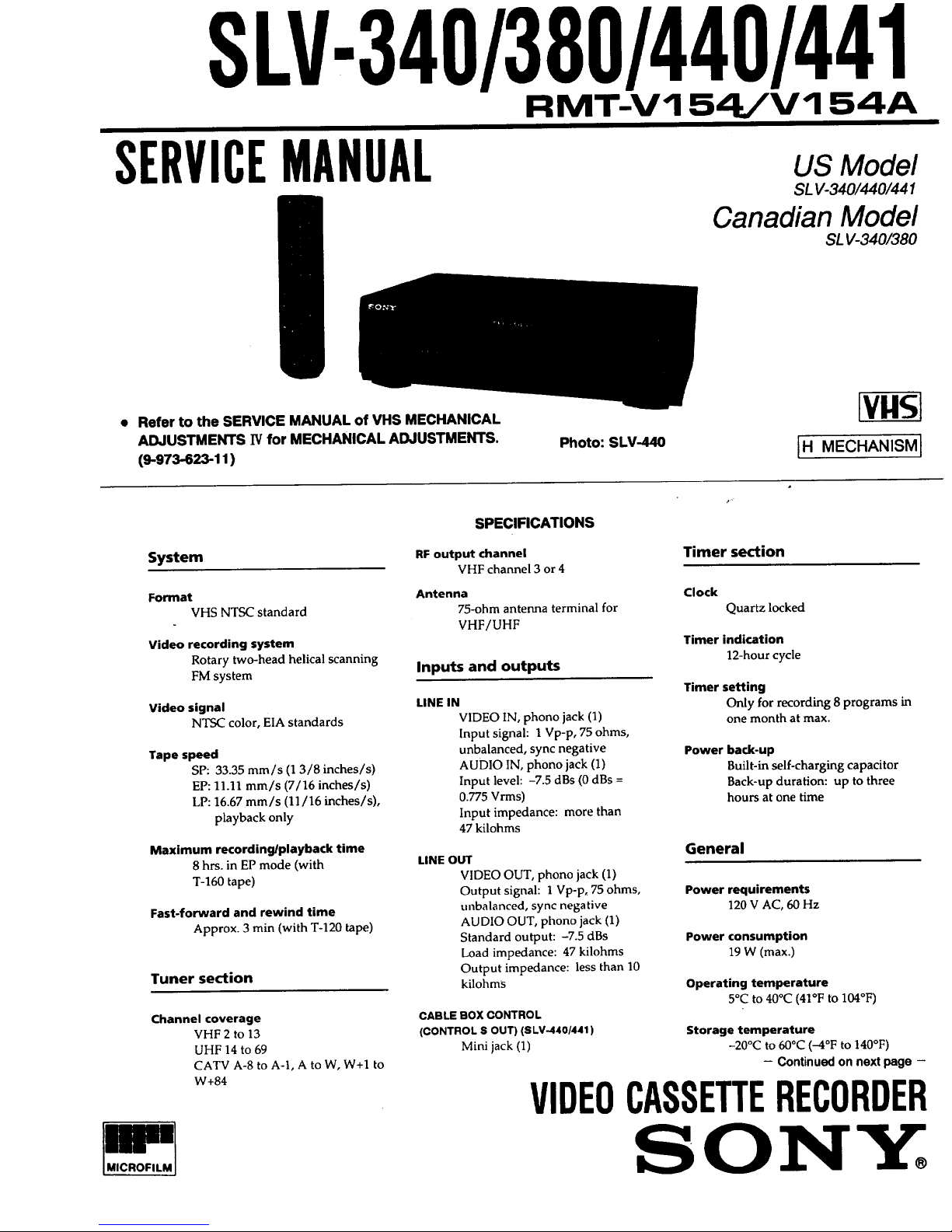
SLV-340/380/440/441
RMT-V154iV 154A
SERVICEMANUAL
US Model
SL V-340/440/441
Canadian Model
SL V-340/380
Refer to the SERVICE MANUAL of VHS MECHANICAL
ADJUSTMENTS IV for MECHANICAL ADJUSTMENTS.
(9-973-623-11 )
Photo: SLV-440 IH
MECHANISM I
System
Format
VHS NTSC standard
Video recording system
Rotary two-head helical scanning
FM system
Video signal
N'IV'-'-'-'-'-'-'-'-_Ccolor, EIA standards
Tape speed
SP: 33.35 mm/s (1 3/8 inches/s)
EP: 11.11 mm/s (7/16 inches/s)
LP: 16.67 mm/s (11/16 inches/s),
playback only
Maximum recording/playback time
8 hrs. in EP mode (with
T-160 tape)
Fast-forward and rewind time
Approx. 3 min (with T-120 tape)
Tuner section
Channel coverage
VHF 2 to 13
UHF 14 to 69
CATV A-8 to A-l, A to W, W+I to
W+84
IBm
IMICROFILM]
SPECIFICATIONS
RF output channel
VHF channel 3 or 4
Antenna
75-ohm antenna terminal for
VHF/UHF
Inputs and outputs
LINE IN
VIDEO IN, phone jack (1)
Input signal: l Vp-p, 75 ohms,
unbalanced, sync negative
AUDIO IN, phone jack (1)
Input level: -7.5 dBs (0 dBs =
0.775 Vrms)
Input impedance: more than
47 kilohms
LINE OUT
VIDEO OUT, phone jack (1)
Output signal: 1Vp-p, 75 ohms,
unbalanced, sync negative
AUDIO OUT, phone jack (1)
Standard output: -7.5 dBs
Load impedance: 47 kilohms
Output impedance: less than 10
kilohms
CABLE BOX CONTROL
(CONTROL S OUT) (SLV-4401441)
Mini jack (1)
Timer section
Clock
Quartz locked
Timer indication
12-hour cycle
Timer setting
Only for recording 8 programs in
one month at max.
Power back-up
Built-in self-charging capacitor
Back-up duration: up to three
hours at one time
General
Power requirements
120 V AC, 60 Hz
Power consumption
19 W (max.)
Operating temperature
5°C to 40°C (41°F to 104°F)
Storage temperature
-20°C to 60°C (-4°F to 140°F)
- Continued on next page -
VIDEOCASSETTERECORDER
SONY
Index to parts and
controls
Refer to the pages indicated in ( ) for details.
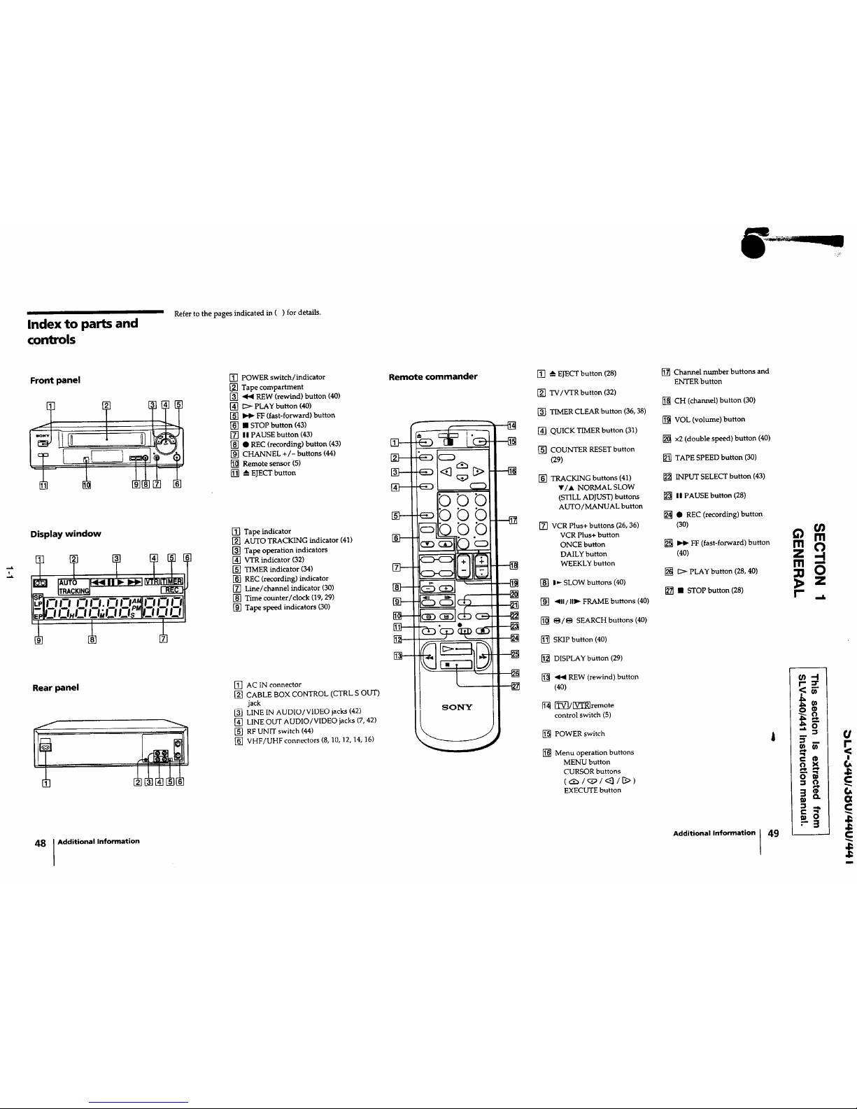
Front panel
2 T
Display window
Rearpanel
48 I Additional Information
[] POWER switch/indicator
[] Tape compartment
[] _ REW (rewind) button (40)
[] _ PLAY button (40)
[] _ FF (fast-forward) button
[] • STOP button (43)
[] ii PAUSE button (43)
[] • REC (recording) button (43)
[] CHANNEL +/- buttons (44)
[] Remote sensor (5)
[] --_ESECT button
[] Tape indicator
[] AUTO TRACKING indicator (41)
[] Tape operation indicators
[] VTR indicator (32)
[] TIMER indicator (34)
[] REC (recording) indicator
[] Line/channel indicator (30)
[] Time counter/clock (19, 29)
[] Tape speed indicators (30)
[] AC IN connector
[] CABLE BOX CONTROL (CTRL S OUT)
jack
[_ LINE IN AUDIO/VIDEO jacks (42)
[] LINE OUT AUDIO/VIDEO jacks (7, 42)
[] RF UNIT switch (44)
[] VHF/UHF connectors (8, 10, 12, 14, 16)
Remote commander [] --_EJECT button (28)
[] TV/VTR button (32)
[] TIMER CLEAR button (36, 38)
[] QUICK TIMER button (31)
[] COUNTER RESET button
(29)
[] TRACKING buttons (41)
V/A NORMAL SLOW
(STILL ADJUST) buttons
AUTO/MANUAL button
[] VCR Plus+ buttons (26, 36)
VCR Plus+ button
ONCE button
DAILY button
WEEKLY button
[] I_- SLOW buttons (;10)
[] "_lfl/[ll_- FRAME buttons (40)
[] _/_ SEARCH buttons (40)
[] SKIP button (40)
[] DISPLAY button (29)
[] _ REW (rewind) button
(40)
[_3/_Zi_remote
control switch (5)
[] POWER switch
[] Menu operation buttons
MENU button
CURSOR buttons
(_/q_/<_l/B>)
EXECUTE button
[] Channel number buttons and
ENTER button
[] CH (channel) button (30)
[] VOL (volume) button
[] x2 (double speed) button (40)
[] TAPE SPEED button (30)
[] INPUT SELECT button (43)
[] I1 PAUSE button (28)
[] • REC (recording) button
(30)
[] _" FF (fast-forward) button
(40)
[] > PLAY button (28, 40)
[] • STOP button (28)
Additional Information 49
(n
m
m O
Z -4
Ill --
0
z
r
<_
i,- rll j
o )<

Welcome!
Step 1: Unpacking
Thank you for purchasing the Sony Video Cassette Recorder (VCR).
Here are some of the features you'll enjoy with your VCR
• VCR Plus+* system that lets you quickly and easily preset the VCR to
record programs
• Cable box control that allows your VCR to control channel selection
on mnst brands of cable boxes
• ON SCREEN HELP messages that warn you of having attempted an
incorrect operation.
*VCR Plus+ and PlusCode are trademarks of Gemstar Development Corp. VCR Plus+
system is manufactured under license from Gemstar Development Corporation.
Check that you have the following items:
• Remote commander
• Size AA (R6) batteries
• Cable Mouse (cable box
controller)
• 75-ohm coaxial (able
with F-type connectors
• AC power cord
(SL V-4401441)
Step 2: Setting up the
remote commander
Notes
• With normal use, the
batteries shouJdlast for
al_ima_ly th_ to six
motlth_
• It you do not u_ the vemote
commander for an extended
period of time, remove the
batteries to avoid possible
damage from battery
leakage.
• Do not use a new battery
with an old o_e.
• Do not use diffevent types of
batteries.
Inserting the batteries
Insert two s_e _ (R6) battenes by matching the + and - onthe
batteries to the diagram inside the battery compartment.
Using the remote commander
You can use this remote commander to operate this VCR and a Sony
TV. Buttons on the remote commander marked with a dot (o) can be
used to operate your "IV.
Remote sensor
To operate
the VCR
a Sony
s.tr_-1,[-_-1_
and point at the remote sensor on the VCR
[] and point at theremotesensor on the "IV
4 I GettingStarted Getting Started [ 5
-.a.
Step 3: Hookups
Caution
Connections between the
VCR's VHF/UI_ connector
and the antel_ terminals of
the TV receiver should be
made only as shown in the
following i_structions. Failure
to do so may result in
operation that violates the
regulations of the Federal
Communications Commission
regardingtheuse and
operationofRF devices.Never
connect the output of the VCR
to an antenna or make
simultaneous (parallel)
antenna and VCR connections
at the antenna ternunals of
your receiver.
Note to CATV system
installer
This remander is provided to
call the CA'IV system
instaUer's attention to Article
820-40 of the NEC that
provides guidelines for proper
grounding and, in particular,
speafies thatthecable ground
shall be conne(:ted to the
grounding system of the
building, as close to the point
of cable entry as practical
Selecting the best hookup option
Before you can use your VCR for the first time, you need to connect it to
your TV and set it up to receive programs for viewing and recording.
This section explains how to hook up and set up your VCR so that you
can start enjoying it right away. There are, however, many types of TVs
available and many ways in which your TV can be hooked up. For these
reasons, this manual describes several ways your VCR can be
connected.
To hook up your VCR so that it works best for you, first scan through
the table below. Then use the accompanying diagrams and procedures
on the following pages to set up your VCR.
If you have Use Refer to
TV that has audio/video inputS Audio/video (A/V) hookup, Page 7
then follow one of the hookups
below.
Cable TV with cable box Hookup 1 Page 8
Cable "['Vwithout cable box Hookup 2 Page 10
Antenna only, no cable TV Hookup 3 Page 12
After you've completed the connections, follow the instructions for
setup including VCR Plus+ setup. During setup, if you need more
details of the procedure described, page numbers are provided where
you can find complete, step-by-step instructions.
After you've completed the setup, you're ready to use your VCR.
Procedures differ depending on the hookup you used. For an overview,
refer to "Quick reference to using the VCR" on the back cover.
Before you get started
• Turn off the power to all equipment.
• Do not connect the AC power cords until all of the connections are
completed.
• Be sure you make connections firmly. Loose connections may cause
picture distortion.
• If your TV doesn't match any of the examples provided, see your
nearest Sony dealer or qualified technician.
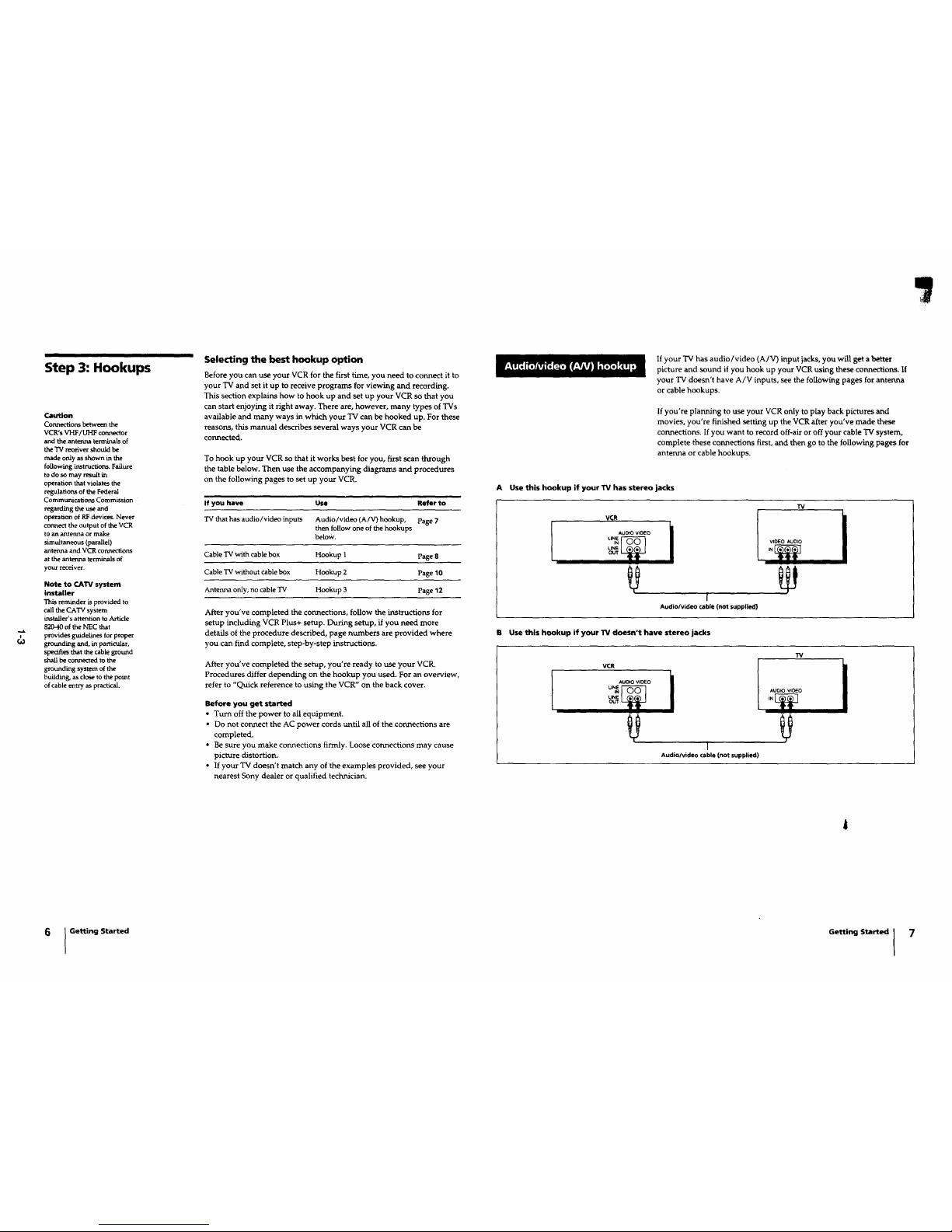
If your TV has audio/video (A/V) input jacks,you will geta better
picture and sound if you hook up your VCR using these connections. If
your TV doesn't have A/V inputs, see the following pages for antenna
or cable hookups.
If you're planning to use your VCR only to play back pictures and
movies, you're finished setting up the VCR after you've made these
connections. If you want to record off-air or off your cable TV system,
complete these connections first, and then go to the following pages for
antenna or cable hookups.
A Use this hookup if your TV has stereo jacks
TV
VCR !
AUOtO WDEO i
u_ _ v,DEO_UO,O
%_ ,_
I
[
Audio/video cable (not supplied)
B Use this hookup if your W doesn't have stereo jacks
TV
VCR
AUDIO VIDEO i
LINEouT IN
I
Audio/video cable Inot supplied)
6 ] GettingStarted
Getting Started I 7
Using cable box
control
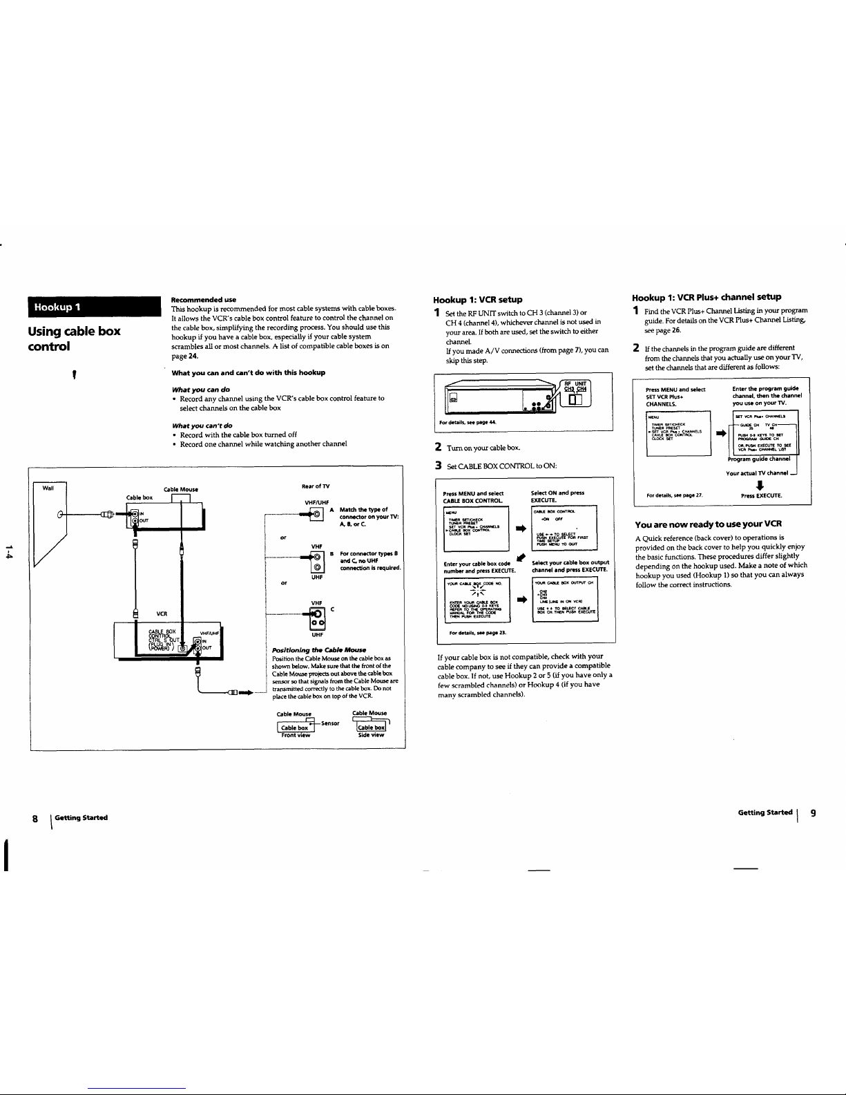
Recommended use
This hookup is recommended for most cable systems with cable boxes.
It allows the VCR's cable box control feature to control the channel on
the cable box, simplifying the recording process. You should use this
hookup if you have a cable box, especially if your cable system
scrambles all or most channels. A list of compatible cable boxes is on
page 24.
What you can and can't do with this hookup
What you can do
• Record any channel using the VCR's cable box control feature to
select channels on the cable box
What you can't do
• Record with the cable box turned off
• Record one channel while watching another channel
Cable Mouse
Cable box
l VCR
I
• ear of TV
VHF/UHF
ml_ A Match the type of•...................... connector on your TV:
A, 8, or C.
or
VHF
B For connector types B
....................... and C. no UHF
connection is R_luired.
UHF
or
VHF
......................... _ C
UHF
Positioning the Cable Mouse
Position the Cable Mouse on the cable box as
shown below. Make sure that the front of the
Cable Mouse projec_ out above the cable box
sensor so that signals from the Cable Mouse are
transmitted correctly to the cable box. Do not
place the cable box on top ofthe VCR.
Cable Mouse Cable Mouse
Front view Side view
Hookup 1: VCR setup
1 Set the RF UNIT switch to CH 3 (channel 3) or
CH 4 (channel 4), whichever channel is not used in
your area. If both are used, set the switch to either
channel.
Ifyou made A/V connections (from page 7), you can
skip thisstep.
For details, see page 44.
2 Turn or_yo_tr cable box.
3 Set CABLE BOX CONTROL to ON:
Press MENU and select
CABLE BOX CONTROL
'" _k
TM[A ,Se'r_[¢K
"rU_A _l_ae'r
SeT VCR _. CH'Ua_LS
Enter your cable box code
numberandpressEXECUTE.
';;k-
I_" ,h_.o%%'_,'%
For details, see page 23.
Select ON and press
EXECUTE.
_wI.E _ c_,rrl_L
USE_ _ YOSELE_
_ _xfCu'rE FOR F,_-n"
TNe SETUP
Select your cable box output
channel and press EXECUTE.
YouACAeUE8OX 0,.nPUT Cl4"__ I
UNEILINEIN ON VCR)
Box CH,T_N PUS" _X[CU_E
If your cable box is not compatible, check with your
cable company to see if they can provide a compatible
cable box. If not, use Hookup 2 or 5 (if you have only a
few scrambled channels) or Hookup 4 (if you have
many scrambled channels).
Hookup 1: VCR Plus+ channel setup
1 Find the VCR Plus+ Channel Listing in your program
guide. For details on the VCR Plus+ Channel Listing,
see page 26.
2 if the channels in the program guide are different
from the channels that you actually use on your "IV,
set the channels that are different as follows:
Press MENU and select
SET VCR Plus+
CHANNELS.
_NU
TI_ERS_T,C_ECK
TUN[_ pn[s_T
_S_ VCR _- C_NNEL_
Enter the program guide
channel, then the channel
you use on your W.
_UlO[ CH W CH_
s_ _1 x_Y$ TO S_
o_. _ EXECUTETO see
ramguidechannel
Your actual TV channel --
!,
For details, SH page 27. Press EXECUTE.
You are now ready to use your VCR
A Quick reference (back cover) to operations is
provided on the back cover to help you quickly enjoy
the basic functions. These procedures differ slightly
depending on the hookup used. Make a note of which
hookup you used (Hookup 1) so that you can always
follow the correct instructions.
8 I Getting Started Getting Started I
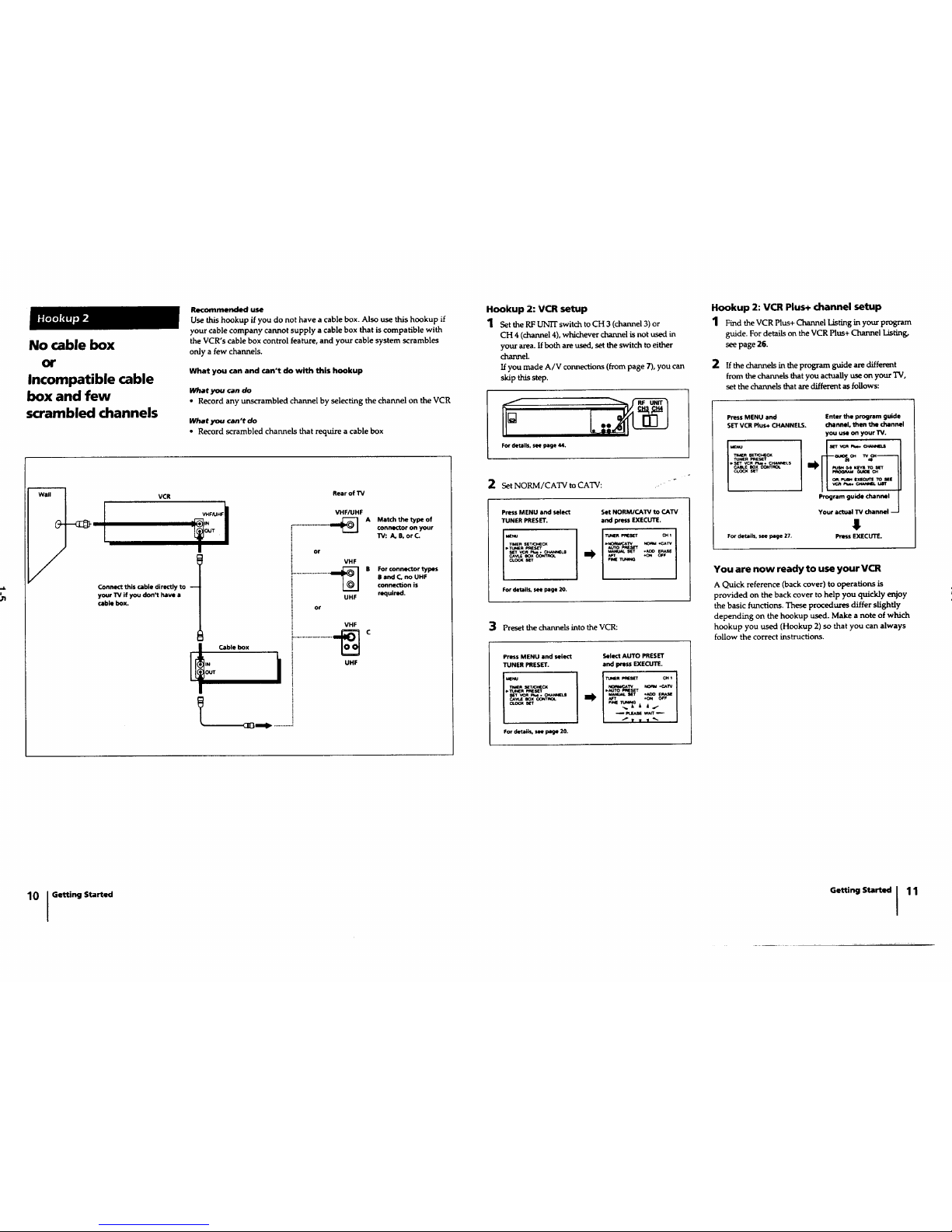
No cable box
or
Incompatible cable
box and few
scrambled channels
Recommended use
Use this hookup if you do not have a cable box. Also use this hookup if
your cable company cannot supply a cable box that is compatible with
the VCR's cable box control feature, and your cable system scrambles
0nly a few channels,
What you can and can't do with this hookup
_at ycai can do
• Record any unscrambled channel by selecting the channel on the VCR
what you can't do
• Record scrambled channels that require a cable box
VCR
Connect this cable directly to --
your TV if you don't have a
cable box.
RearofTV
VHF/UHF
A Match the type of
•...................... connector on your
13/: A, B, or C.
JT Cable box
I
__[Om,_ ............
or
VHF
....................... _ B connectionBF°randC°nnect°rc'no isUHFtypeS
UHF required.
or
i VHF
........................ _UHF C
Hookup 2: VCR setup
1 Set the RFUNrr switch to CH 3 (channel 3) or
CH 4 (channel 4), whichever channel is not used in
your area. Ifboth are used, set the switch to either
channel.
Ifyou made A/V connections (from page 7), you can
skip this step.
1
FOr details, see page 44,
2 Set NORM/CATV to CATV:
Press MENU and select
TUNER PRESET.
I.E.. m_
TIMER SEY_
pT_4m _S_'T
s_ vcn _ + C_N_LS
CA_.E ecx C_TI_.
CL_ SET
Set NORM/CATV to CATV
and press EXECUTE.
TU_M _eseT c_ 1
,NOm_¢XTV NORM.CAW
JUTO_S_
Fro(
For details, see page 20.
3 Preset the channelsinto the VCR:
Press MENU and select
TUNER PRESET.
1"2 o
For details, m page 20.
Select AUTO PRESET
and I_'ass EXECUTE.
NOm_C_TV _owa .CArV
Hookup 2: VCR Plus. channel setup
1 Findthe VCR Plus+ Channel Listing in your program
guide. Fordetails on theVCR Plus+ Channel Listing,
seepage 26.
2 , the channels in the program guide are different
from the channels that you actually use on your TV,
set the channels that are different as follows:
Press MENU and
SET VCR Plus+ CHANNELS.
Td_n S_CX
TU_R PRESET
.SET VCR _,.. CHANNELS
Enter the program guide
channel, then the channel
you use on your TV.
Program guide channel
Your actual TV channel --
$
For details, see page 27. Press EXECUTE.
You are now ready to use your VCR
A Quick reference (back cover) to operations is
provided on the back cover to help you quickly enjoy
the basic functions. These procedures differ slightly
depending on the hookup used. Make a note of which
hookup you used (Hookup 2)so that you can always
follow the correct instructions.
10 [ GettingStarted
Getting Started I 11
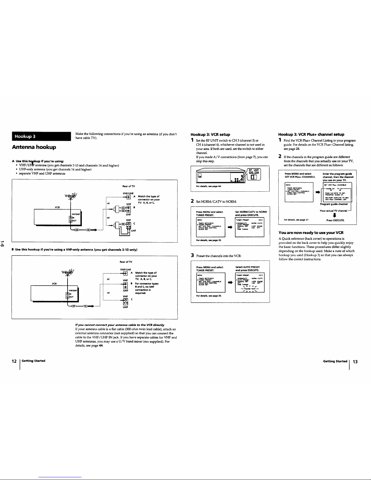
Antenna hookup
Make thefonowing connections ifyou're using anantenna(ff you don't
havecableTV).
A Use this hc_okup if you're using:
• VHF/UI_ antenna (you get channels 2-13 and channels 14 and higher)
• UHF-only antenna (you get channels 14 and higher)
• separate VHF and UHF antennas
VCR
Rear of TV
VHF/UHF
.......................... _] A Match the type of
connector on your
i or VHF W: A. B, or C.
! ior
,, VHF
T I i i....__
_'_{]]D'_I'(]_ _ ""'"_ --_UHF
B Use this hookup if you're using a VHF-only antenna (you get channels 2-13 only)
Rear ofTV
I
VCR
VHF_LIHF
VHF/UHF
_] A Match the type of
connector on your
or VHF TV: A, B, or C.
.............................. U_HF B For connector types
i B and C, no UHF
i connection is
or required.
VHF
i!_" .__ c
UHF
Hookup 3: VCR setup
1 SettheRE_ switch_oCH3 (channel 3)or
CH 4 (channel 4), whichever channel is not used in
your area. If both are used, set the switch to either
channel.
If you made A/V connections (from page 7), you can
skip this step.
For details, see page 44.
2 Set NORM/CATV to NORM:
Press MENU and select
TUNER PRESET.
MENU
riMER S_ECK
_irwin eeeseT
_T VCR _.6. C_'U_ELS
For details, see page 20.
Set NORM/CAW to NORM
and press EXECUTE.
I
TUNER_stElr r_ 2
_NO_ArV NORM .cAw
ALrro _e T_-n-
3 Preset the channels into the VCR:
Press MENU and select
TUNER PRESET.
[';oo
n_En s_H[cx
For details, sN p_Je 20.
Select AUTO PRESET
and press EXECUTE.
NO_a_TV NORM._q'rV
_AUTOP_SET
sk-r ,ADO ERA_
_s_ W_T _ I
I
Hookup 3: VCR Plus+ channel setup
1 _mdtheVC_Plus+thee] _ inyourp_._
guide. For details on the VCR Plus+ Channel listing,
see page 26.
2 If the channels in the program guide are different
from the channels that you actually use on your "IV,
set the channels that are different as follows:
press MENU and select
SET VCR Plus+ CHANNELS.
_NU
TUNER _
.S_T vcn_. CH_NNEkS
Enter the program guide
channel, then the channel
you use on your W.
s_ VCR_ CH,U_S_S
programguide channel I
Your actual TV channel -_
!
For details, see page Z7. Press EXECUTE.
You are now ready to use your VCR
A Quick reference (back cover) to operations is
provided on the back cover to help you quickly enjoy
the basic functions. These procedures differ slightly
depending on the hookup used. Make a note of which
hookup you used (Hookup 3) so that you can always
follow the correct instructions.
If you cannot connect your antenna cable to the VCR directly
If your antenna cable is a flat cable (300-ohm twin lead cable), attach an
external antenna connector (not supplied) so that you can connect the
cable to the VHF/UHF IN jack. If you have separate cables for VHF and
UHF antennas, you may use a U/V band mixer (not supplied). For
details, see page 44.
12 I GettingStarted
Getting Started 113
 Loading...