

Page 1
3-751-564-21 (1)
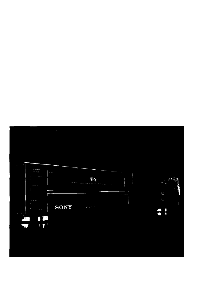
Video Cassette Recorder
Operating Instructions
vus
© 1990 by Sony Corporation
Page 2
WARNING
Owner’s Record
To prevent fire or shock hazard, do not expose the unit to rain or moisture.
CAUTION
RISK OF ELECTRIC SHOCK
DO NOT OPEN
CAUTION; TO REDUCE THE RISK OF ELECTRIC SHOCK,
DO NOT REMOVE COVER (OR BACK).
NO USER-SERVICEABLE PARTS INSIDE,
REFER SERVICING TO QUALIFIED SERVICE PERSONNEL.
This symbol is intended to alert the user
to the presence of uninsulated "dangerous
voltage” within the product’s enclosure
that may be of sufficient magnitude to
constitute a risk of electric shock to
persons.
This symbol Is intended to alert the user
to the presence of important operating and
maintenance (servicing) instructions in the
literature accompanying the appliance.
The model number is located at the rear and front of the unit
and the serial number on the top. Record the serial number
in the space provided below. Refer to these numbers
whenever you call upon your Sony service dealer regarding
this product.
Model No. SLV-373UC Serial No.
______________________
For the Customers in the U.S.A.
INFORMATION
This equipment generates and uses radio frequency
energy and if not instaiied and used properiy, that is, in
strict accordance with the manufacturer’s instructions,
may cause interference to radio and teievision reception.
It has been type tested and found to comply with the limits
for a Class B computing device in accordance with the
specifications in Subpart J of Part 15 of FCC Rules, which
are designed to provide reasonable protection against
such interference in a residential installation. However,
there is no guarantee that interference will not occur in
a particular installation. If this equipment does cause
interference to radio or television reception, which can be
determined by turning the equipment off and on, the user
is encouraged to try to correct the interference by one or
more of the following measures:
Reorient the receiving antenna
Relocate the equipment with respect to the receiver
Move the equipment away from the receiver
Plug the equipment into a different outlet so that
equipment and receiver are on different branch circuits.
If necessary, the user should consult the dealer or an
experienced radio/television technician for additional
suggestions. The user may find the following booklet
prepared by the Federal Communications Commission
helpful:
“How to Identify and Resolve Radio-TV Interference
Problems”.
This booklet is available from the U.S. Government
Printing Office, Washington, DC 20402, Stock No.
004-000-00345-4.
-----
Note to CATV system installer: -----------------------------
This reminder is provided to call the CATV system
installer's attention to Article 820-22 of the NEC that
provides guidelines for proper grounding and, in particular,
specified that the cable ground shall be connected to the
grounding system of the building, as close to the point of
cable entry as practical.
For the Customers In Canada
TO PREVENT ELECTRIC SHOCK, DO NOT USE THIS
POLARIZED AC PLUG WITH AN EXTENSION CORD,
RECEPTACLE OR OTHER OUTLET UNLESS THE
BLADES CAN BE FULLY INSERTED TO PREVENT
BLADE EXPOSURE.
Page 3

able of Contents
L
Preliminaries
Preparations
Operations
Precautions .................................................................................................................................. 4
Introduction .................................................................................................................................. 5
Identifying the Operational Parts .................................................................................................. 6
Connections .................................................................................................................................12
About the MENU Display ..............................................................................................................20
Date and Clock Setting ................................................................................................................ 22
Presetting Active Channels...........................................................................................................24
Handling Video Cassettes.............................................................................................................28
Piqitoeili
Playing a Tape .............................................................................................................................29
flaeiKiiMsi
Recording TV Programs ...............................................................................................................36
Use of the Tape Counter ..............................................................................................................38
Timer Recording ...........................................................................................................................40
Quick Timer Recording ................................................................................................................48
Index Function ..............................................................................................................................50
ftfWng
Editing with Another VCR .............................................................................................................53
Editing with a VCR without a Sony Control Terminal ...................................................................54
Editing with a VCR with a Control S Out Terminal........................................................................56
Other Information
Indications in the Display Window ................................................................................................57
Troubleshooting ............................................................................................................................58
Specifications................................................................................................................Back cover
Page 4

Precautions
On Safety
• Operate the unit only on 120V AC, 60 Hz.
• Should anything fail into the cabinet, unplug the unit
and have it checked by qualified personnel before
operating it any further.
• One blade of the plug is wider than the other for the
purpose of safety and will fit into the power outlet only
one way. If you are unable to insert the plug fully into
the outlet, contact your dealer.
• Unplug the unit from the wall outlet if it will not be used
for an extended period of time. To disconnect the cord,
pull it out by the plug. Never pull the cord itself.
On Installation
• Allow adequate air circulation to prevent internal heat
build-up.
• Do not place the unit on surfaces (rugs, blankets, etc.)
or near materials (curtains, draperies) that may block
the ventilation slots.
• Do not install the unit near heat sources such as
radiators or air ducts, or in a place subject to direct
sunlight, excessive dust, mechanical vibration or shock.
• The unit is designed for operation in a horizontal
position. Do not install it in an inclined position.
• Keep the unit and cassette tapes away from equipment
with strong magnets, such as microwave ovens or large
loud speakers.
• Do not place any heavy object on the unit.
On Operation
On Cleanii^'
• Clean the cabinet, panel and controls with a dry, soft
cloth, or a soft cloth slightly moistened with a mild
detergent solution.
• Do not use any type of solvent, such as alcohol or
benzine, which might damage the finish.
On Rep^Mns
• Do not throw away the carton and packing materials.
They make an ideal container in which to transport the
unit. When shipping the unit to another location, repack
it as illustrated on the carton.
If you have any questions about this unit, contact your
Sony dealer or a qualified technician.
• When the unit is not in use. turn the power off to
conserve energy and to extend the life of the unit.
• Remove and store video cassettes after recording or
playback.
• Store the cassettes in their cases and keep them in an
upright position to prevent intrusion of dust and uneven
winding.
Page 5

Introduction
How to Urna Thte Mamial Oran^W of №e SLV-873UC
This manual is arranged to help you quickly find the
information you need for the operation of the
SLV-373UC.
This manual consists of the following four sections.
^ Preliminaries
2 Preparations
3 Operations
^ Other Information
First, look through the Table of Contents. If you are
already familiar with VCR operation, read starting from
the "Preparations” section. If you are new to VCR
operation, start with “Identifying the Operational
Parts" (page 6) to familiarize yourself with this unit. To
have a quick overview of the operation of this unit, refer
to “Playing a Tape” (page 29), “Recording TV
Programs” (page 36), and “Timer Recording” (page 40).
Before Yea №gln
• Check that the following accessories are in the carton
with your unit:
• Remote Commander RMT-V373A (1)
• Size AA (R6) batteries (2)
• External antenna connector (1)
•75-ohm coaxial cable with F-type connectors (1)
•AC power cord (1)
* In the text of this manual,
shown in capital letters:
Example: Press PLAY.
• The buttons on the Commander and the unit with the
same mark have the same functions.
• Notes are enclosed in boxes.
buttons and switches are
I For Editing
• DUAL MODE SHUTTLE ring
Allows easy operation and quick access to the desired
scene.
•CONTROL S INPUT )ack
Allows remote control of this VCR by other Sony video
equipment with a CONTROL S OUTPUT jack.
• Input connectors on the front panel
Offers easy connection to a video camera recorder.
I On-screen displays
• Data screen
Tape counter, tape speed, operation mode, and
remaining tape length are displayed on the TV screen.
• AUTO MENU display
Allows selection of an automatic tape operation on the
TV screen.
• TIMER SET/CHECK display
Timer recording settings can be set and checked by
referring to the TV screen.
I Convenient Functions
• Auto tracking function
Automatically adjusts the tracking condition for
maximum picture quality.
• Timer recordings of 8 programs over a month
Recording of up to eight TV programs can be preset as
much as one month in advance.
•Index function
The beginning of a desired scene can be located easily
with the index mark/index search function.
• SWING SHUTTLE dial on the Commander
Allows playback in various speeds in forward and
reverse directions.
•Auto Head Cleaner
The video heads will automatically be cleaned each
moment the power is turned on, the tape is loaded or
ejected, for at least 50,000 times.
I High quaiity picture
•High quality (HQ) picture
The SLV-373UC provides sharp, finely detailed pictures
through High Quality (HQ) picture technology.
HQ A video cassette recorder (VCR) with this marking
incorporates VHS high-quality picture technology and is
compatible with any video cassette recorder bearing the
VHSi mark.
* •
?
3
CO
Page 6
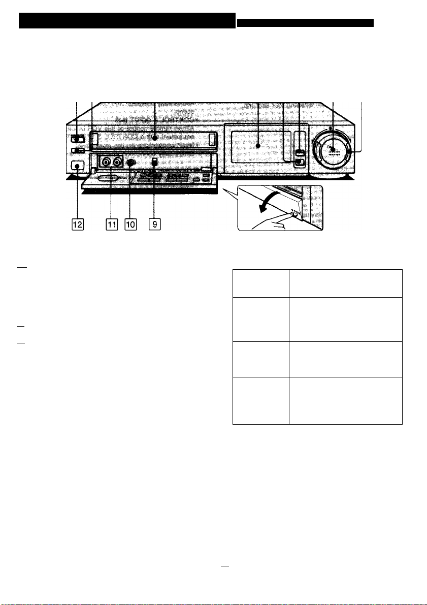
Identifying the Operational Parts Refer to the pages indicated for detaiis.
00 0
pT] POWER ON/OFF switch and indicator
Press to turn on and off the power of the unit. The
indicator lights when power is supplied,
A eject button
Press to eject the cassette.
[y| Cassette compartment
[4] Display window and function mode display
Various displays appear. See “Indications in the
Display Window.” (page 57)
■ STOP button
Press to stop the tape.
M/PM PAUSE/STILL button (page 33)
In the playback mode: Press to obtain a still picture.
In the recording mode: Press to pause recording
temporarily.
0 > PLAY button
Press to playback the tape.
0 00 0 0
DUAL MODE SHUTTLE ring (page 33)
In the stop
mode
In the playback
mode
In the fastforward mode
In the rewind
mode
COMMAND MODE selector (page 9)
To remotely control this VCR with the supplied
wireless Commander, set this selector to the same
position as that on the Commander. Usually set to
VTR 3.
SHARPNESS SOFT/SHARP control (page 35)
Use to adjust the sharpness of the picture if
necessary. Normally set this control at the center
position.
LINE IN 2 VIDEO and AUDIO jacks (phono type) (page 54)
Connect to the video/audio output jacks of another
VCR or a video camera recorder,
|f^ Remote sensor
Point the supplied Commander here.
Turn to the right (►►) to advance
the tape rapidly, and to the left
(■44) to rewind the tape.
Turn to the right (FORWARD) to
advance and to the left
(REVERSE) to reverse the picture
in various speeds including a still
picture when the ring is released.
Turn to the right (FORWARD) to
view the picture in fast speed.
The unit will return to fast-forward
when the ring is released.
Turn to the left (REVERSE) to
view the picture in fast speed
reverse. The unit will return to
rewind mode when the ring is
released.
Page 7
Insicie of №• Front Panel
|T] ANT TV/VTR button (page 37)
When connecting the VCR and a TV via the VHP
antenna terminal, press this button so that VTR
indicator lights in the display window. When you wish
to watch one TV program while recording another,
press this button again so that the VTR indicator is
turned off.
INPUT SELECT button (page 36)
Press so that the desired input mode indicator
appears in the display window to select the program
to be recorded. The ihdicator changes as follows:
TUNER and channel number LINE LI
L
---------
1 LINE L2 h
REC MODE (SP/EP) button (page 28)
Press to select the recording tape speed, SP or EP.
When playing back, the tape speed will be
automatically detected regardless of the setting of
this button.
EDIT ON/OFF button (page 53)
Normally keep this button at OFF (i.e. the EDIT
indicator turned off). When using this VCR for
editing, press this button so that the EDIT indicator
lights.
@ TIMER REC ON/OFF button (page 41)
Press this button to enter the timer recording standby
mode. Press it again to release the timer recording
standby mode before changing or canceling a timer
recording or to operate the unit before a timer
recording starts.
-------------------
QUICK TIMER button (page 48)
Press to start quick timer recording and to set the
recording duration.
-**4 HIGH SPEED REWIND button (page 30)
|T| • REC button (page 36)
TRACKING AUTO/MANUAL button (page 35)
Press to re-activate the automatic tracking function
after using the manual tracking adjustment.
I
'
TRACKING NORMAL/SLOW and STILL ADJUST T/A buttons (page 34)
Press to clear streaks if they appear on the screen in
normal and slow playback (= normal/slow tracking).
Press to reduce picture shaking in the still mode
(= still adjust).
CHANNEL +/- buttons (page 36)
Press to select the TV chahnels. Press + to advance
and - to go back.
Page 8
Identifying the Operational Parts
Rear Panel
pT|
RF UNIT selector (page 19)
Use to select the channel for VCR playback, 3 CH or
4 CH, whichever is not active in your area.
VHF/UHF IN/OUT connectors (F-type) (page 13)
Connect to the VHF/UHF connectors on your TV
referring to the “Connections” section.
LINE IN 1 VIDEO and AUDIO jacks (phono type)
Connect to the video/audio output jacks of another
VCR.
AC IN jack
Connect the supplied AC power cord. Then connect
the AC power cord to the wall outlet.
[s] CONTROL S IN jack (mini type) (page 56)
Connect to the CONTROL S output jack of another
Sony product for systematic operations such as
synchronized editing.
LINE OUT VIDEO and AUDIO jacks (phono type) (page 17, 55)
Connect to the video/audio input jacks of another
VCR.
8
Page 9
Remote Commanuier
•The buttons on the Commander with the same
name or mark as those on the unit have the
same function.
• The buttons on the Commander with a red dot
is operable to control the TV even when the
I TV 1/1VTRI selector is set to |TV1
Q COMMAND MODE selector (page 6)
To remotely control the VCR with the Commander,
set this selector to the same position as that on the
unit. Normally set to VTR 3. Change the position as
shown below to control other Sony VCRs:
VTR 1; For Sony Betamax format VCRs
VTR 2: For Sony 8mm format VCRs
VTR 3: For Sony VMS format VCRs
[T| Channel number buttons
0 ENTER button
Used to enter channel numbers. For example, to
select channel 10, press 1, 0, and then ENTER.
[Tl MENU button (page 20)
Press to enter the MENU mode. Press again to get
out of the MENU mode.
[s] EXECUTE button and cursor shift ▲/▼/-4/^
buttons
Use to preset items in various menu operations.
Щ ANT TVAfTR (Antenna TV/VTR) button (page 37)
When connecting the VCR and a TV via the VHP
antenna terminal, press this button so that VTR
indicator lights in the display window. When you wish
to watch one TV program while recording another,
press this button again so that the VTR indicator is
turned off.
0 POWER switch
fa] jTV|/|VTR| remote control selector
Set to I VTR I to use the Commander to control the
VCR. Set to |TV|to use the Commander to control
the TV.
INPUT SELECT button (page 36)
Press to select the source to be recorded. The
selected input mode indicator will appear in the
display window.
CHANNEL +/- buttons (page 36)
Press to change the channel. When the |tv|/|vTr1
remote control selector is set to TV|, the channels on
the TV can be changed. When the |tv|/|vTr1 remote
control selector is set to |VTR|, the channels on the
VCR can be changed.
|ii] VOL +/- buttons
Press to control the TV’s volume.
[l^ REC MODE button (page 26)
Press to select the recording tape speed, SP or EP.
When playing back, the tape speed will be
automatically detected regardless of the setting of
this button.
Function of buttons [l^ and |iT|
These buttons can be used to remotely control Sony
TVs with the H mark.
Page 10
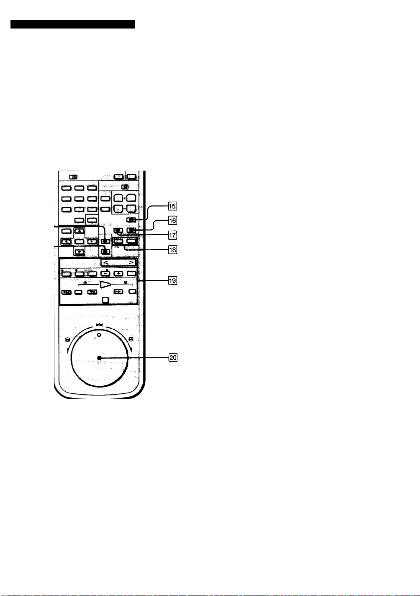
Identifying the Operationai Parts
Remote CommiRfler
TIMER CLEAR button (page 45)
Use to clear timer settings.
TIMER REC (ON/OFF) button (page 41)
Press this button to enter the timer recording standby
mode. Press it again to reiease the timer recording
standby mode before changing or canceling a timer
recording or to operate the unit before a timer
recording starts.
INDEX button (page 51)
Press to enter the index mode.
[l^ DATA SCREEN button (page 30)
Press to turn on and off the on-screen display.
[l^ COUNTER RESET button (page 38)
Press to reset the counter to OHOOMOOS.
[l^ INDEX MARK/ERASE buttons (page 50, 52)
Press MARK to mark an index signal at the desired
point on a tape during recording or playback. To
erase a previously recorded index signal, locate the
index signal and press ERASE.
Q Tape transport buttons
< DIRECTION > (Press to determine
the direction of >PLAY, x 2, and !► SLOW.
During still mode, frame-by-frame picture is
available with this button.)
X 2 (double-speed)
SLOW (-I-: to increase the speed, to
reduce the speed)
• REC (Press the two buttons simultaneously)
II PAUSE
> PLAY
©/© SEARCH (reverse/forward)
►► FF (fast-forward)
◄◄ REW (rewind)
■4*4 HIGH SPEED REWIND
■ STOP
g SWING SHUTTLE dial (page 33)
Turn the dial to playback the tape in various speeds.
The available speeds are reverse search, -X2, -XI,
-X1/5, still (bH), X1/5, XI, X2, and forward search.
10
Page 11
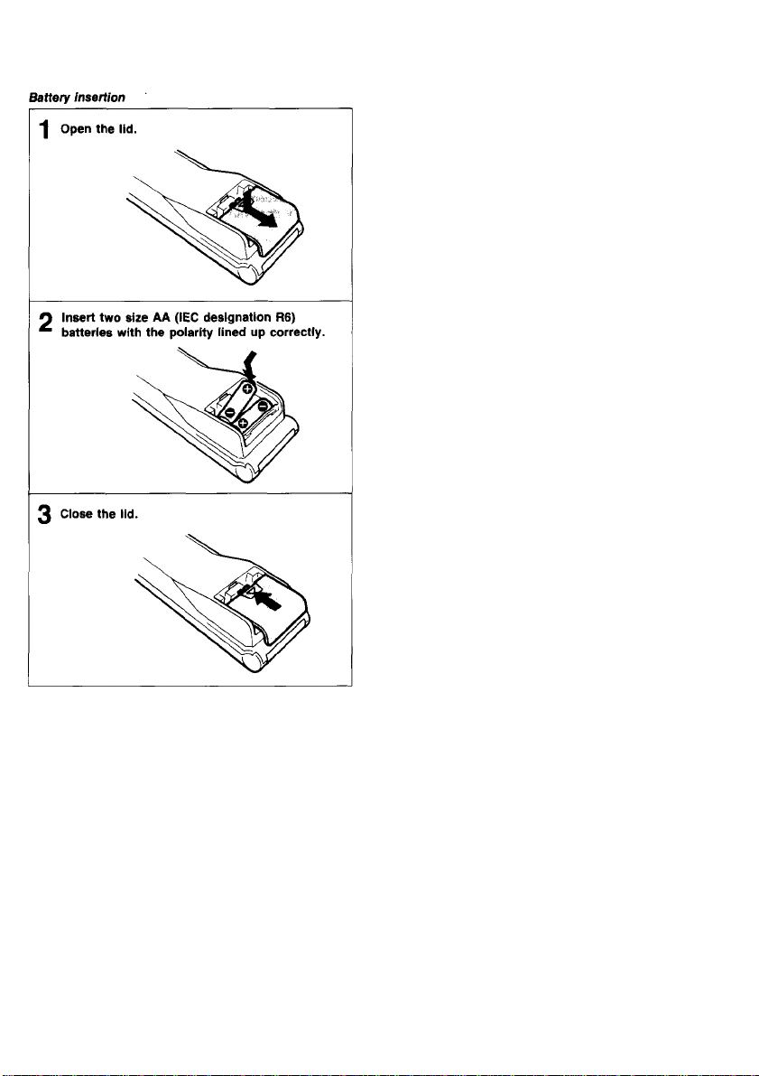
Notes on the handling of batteries
• With normal operation, the batteries will last for
approximately 6 months.
• If the Commander will not be used for a long period of
time, remove the batteries to avoid possible damage from
battery leakage.
11
Page 12
Connections
In order to watch the playback picture on the TV screen
and to receive TV programs on this VCR, the VCR and
the TV receiver must be connected properiy. The
connection between the two units varies depending upon
the type of TV receiver and antenna that you have. We
wiil show you some typicai ways to make connections
with the suppiied accessories. Before operating the unit,
go through this section and make the correct
connections.
First Check Your TV
If your TV does not have video and audio input jacks
Check the antenna terminals on your TV
75-ohm VHF/UHF antenna terminal
VHF/UHF
VHF and UHF separate antenna terminals
Before You fogin...
• Turn off the power to the VCR and the TV.
• Do not connect the AC power cords untii ali of the
connections are completed.
• Make connections firmly. Loose connections may cause
picture distortion.
• If your TV does not match the three examples
below...
Consult your nearest Sony dealer or qualified
technician.
If your TV has video and
audio input jacks
Yellow ^ VIDEO
Black ^ AUDIO
Go through “Connection Examples 1 to 5” to find the appropriate
connections.
Then read “Setting the RF Unit” to view the playback picture of the VCR
on the TV.
Caution
Connections between the recorder VHF/UHF OUT connector and the antenna
terminals of a TV receiver should be made only as shown in the instructions.
Failure to do so may result in operation that violates the regulations of the Federal
Communications Commission regarding the use and operation of rf devices.
Never connect the output of the recorder to an antenna or make simultaneous
(parallel) antenna and recorder connections at the antenna terminals of your
reciever.
12
You can enjoy a better quality
picture by connecting the
VCR and TV via these jacks.
Go to "Connection Example
6.”
Page 13
Cean^ton Exnnpie 1 — To Connect a
ComUnaHon VHF/UHF Antenna
ConiM^ton Example 2 To OMvwct a VHF
Antenna Only
Disconnect the TV antenna cable from the TV
1
receiver and connect it to the VCR.
Connect the VCR and the TV.
2
If the TV has a single terminal for the VHF/UHF
antenna:
Use the 75-ohm coaxial cable (supplied).
If the TV has separate antenna terminals for
VHF/UHF:
Use the EAC-66 U/V band separator/mixer (not
supplied).
How to attach the U/V band separator/mixer and the
F-type connector
See pages 18 and 19.
H Disconnect the TV antenna cable from the TV and
' connect it to the VCR.
If the antenna cable is a 75-ohm coaxial (round)
type.
Use the F-type connector (not supplied).
If the antenna cable is a 300-ohm twin lead (flat)
type:
Use the antenna connector (supplied).
O Connect the VHF/UHF OUT on the VCR and the
^ VHF IN terminal on the TV with the 75-ohm
coaxial cable (supplied).
How to attach the antenna connector and the F~type
connector
See pages 18 and 19.
13
Page 14
CtMtlMOttm» &auni|Me 3 i tm# 4Menna
Whan 0w VHF/UHF anteona ttnnAiaf oil №• TV [if
□
to cofflMmd
UHF
When the VHFAJHF antenna terminal on the TV
are eeparatea
UHF
'4 Connect the antenna connector (supplied) to the
' antenna cable.
O Connect the antenna connector to VHF/UHF IN on
^ the VCR.
O Connect VHF/UHF OUT on the VCR and the
VHF/UHF antenna terminal on the TV.
How to attach the antenna connector
See page 19.
14
4 Connect the antenna connector (supplied) to the
' antenna cable.
O Connect the antenna connector to VHF/UHF IN on
^ the VCR.
Connect the EAC-66 U/V band separator/mixer
3
(not supplied) to the VHF/UHF OUT on the VCR.
A Connect the EAC-66 U/V band separator/mixer to
** the VHF and UHF antenna terminals on the TV.
How to attach the antenna connector and the U/V
band separator/mixer
See page 19.
Page 15
<^Hmeetton Exwilfri« 4 — To Connect botti VHF and OHF Antenna»
When tta VHF/UHF anfanna Uumhtaf on tbe TV
AieemMnad
UHF
VHF
Whon №e VHF/VHf antenna twmtnal* on tht
" TYuatopmtma
UHF VMF
Connect the EAC-66 U/V band separator/mixer
1
(not supplied) to the VHF and UHF antennas.
Connect the EAC-66 U/V band separator/mixer to
2
the VHF/UHF IN on the VCR.
Connect VHF/UHF OUT on the VCR and the
3
VHF/UHF antenna terminal on the TV.
How to attach the U/V band separator/mixer and the
F-type connector
See pages 18 and 19.
H Connect the EAC-66 U/V band separator/mixer
' (not supplied) to the VHF and UHF antennas.
Connect the EAC-66 U/V band separator/mixer to
the VHF/UHF IN on the VCR.
Connect the EAC-66 U/V band separator/mixer to
3
the VHF/UHF OUT on the VCR.
4 Connect the EAC-66 U/V band separator to the
^ VHF and UHF antenna terminals on the TV.
How to attach the U/V band separator/mixer and the
F-type connector
See pages 18 and 19.
15
Page 16
Conneetfon Example 5 — To ConnMi ■ Mia TV SyrtMt
iff yeor lV Am a buKUn CATV ctocactM
CATV KOhni oowaicMii
not Aaw a-Mffln CATV
CATV
A connection example is given above, but we
recommend that you consult your cable company to
make sure that the cable is properly connected.
How to attach the U/V band separator/mixer and the
F-type connector
See pages 18 and 19.
16
Connect the cable TV channel converter between the TV
and the VCR. By setting the ANT TVAn'R switch to TV,
you can watch a cable TV program while playing back or
recording video sources using the VIDEO LINE IN jack
on the VCR.
Now to attach the F-type connector
See page 18.
Page 17
Connection Examfrfe 6 - To ComM:t a TV Bqu^piO wNK VM^AucH« M|M Jacks
How to attach the F-type connector
See page 18.
H your TV is a stereo type
Use the VMC-910MS/920MS connecting cable (not
supplied).
For a high-quality picture, connect a color monitor or a
TV equipped with video/audio input jacks.
Connect the VHF/UHF antenna to the VHF/UHF IN
1
on the VCR.
Connect the VHF/UHF OUT on the VCR and the
2
VHF/UHF IN terminal on the TV with the supplied
75-ohm coaxial cable.
Connect the LINE OUT jacks on the VCR and the
video/audio input jacks on the TV with the video
connecting cable and audio connecting cable.
17
Page 18
18
Page 19

How to attach the external antenna connector (supplied)
^ Loosen the screws on the antenna connector.
p Fit the 300-ohm twin iead <
p Fit the 300-ohm twin iead cabie on the UHF antenna under the
^ screws on antenna connec
^ screws on antenna connector.
3 Tighten the screws again.
How to attach the EAC-66 U/V band separator/mixer (not supplied)
^ Loosen the screws on the U/V band separator/mixer.
Fit the 300-ohm twin iead cable on the UHF antenna under the
2
screws.
Connect the 75-ohm coaxial cable to the U/V band
3
separator/mixer.
A Connect the U/V band separator/mixer to the VHF/UHF IN on the
^ VCR.
the RF Unit
Why this setting is necessary
Your TV receiver must be set to receive the signal from
your VCR. To get the proper RF signal, set the RF UNIT
selector switch on the rear panel ot the VCR. If channel
4 Is active in your area, set the switch to 3 CH, and vice
versa. If you connect a color monitor or a TV
equipped with video/audio input jacks, you do not
need to make this adjustment.
1
2
3
4
Your TV is now tuned to the VCR. Whenever you use the
VCR, set the TV to the channel selected above.
- 300-ohm twin
lead cable
Set the RF UNIT at the rear to 3 CH or 4 CH,
whichever is not active in your area.
Press POWER.
The indicator will light.
Press ANT TV/VTR so that the VTR indicator
lights.
Check that the TUNER indicator appears in the
display window, then select an active channel in
your area by pressing CHANNEL +I-.
Turn on the TV and set the TV to the channel
selected in step 1.
The TV program selected on the VCR will appear on
the screen.
Note
For details about TV channel adjustment, see the instruction manual of the TV.
19
Page 20

About the MENU Display
The SLV-373UC is equipped with a menu dispiay
function. Menu display enables you to perform certain
operations which are displayed on the TV or the monitor.
First display the main MENU, and select the item to be
operated or preset.
Main MENU Display
MENU
►AUTO MENU
TIMER SET/CHECK
TUNER PRESET
CLOCK SET
Mew te OMfMy Me IMn IffiNU
1
Note
The position of the cursor is retained as long i
cord is connected.
Before you begirt
Check the connections between the VCR and the TV.
Operation
Turn on the TV.
1
If your TV is connected to both VHF/UHF OUT
and LINE OUT on the VCR.
Select the input for the VCR.
If your TV is connected only to the VHF/UHF OUT
on the VCR.
Select the channel for the VCR (3 CH or 4CH).
2 Press POWER.
Press ANT TV/VTR so that the VTR indicator
3
lights.
(Only for TVs without video/audio input jacks.)
A Press MENU.
^ The main MENU will appear on the screen.
3 Move cursor to the desired menu by A or ▼. 0 Press EXECUTE.
'' The selected MENU will appear on the screen.
i the power
20
To erase the main MENU display
Press MENU again.
To display other MENU displays
1 Press MENU to erase the present display.
2 Press MENU again to display main MENU.
3 Move cursor to the desired menu.
4 Press EXECUTE.
Page 21

Details of Each Wtenu
Here is a list of the menus in the main MENU. For
details, refer to the sections indicated.
AUTO MENU
TIMER SET/CHECK
TUNER PRESET
CLOCK SET
Use to select an automatic tape operation.
See “Presetting the VCR’s Operation — Auto Play” (page 31).
Use to preset a timer recording and. let’s you check the settings.
See “Timer Recording” (page 40).
Use to preset the active channels in your area.
See “Presetting Active Channels” (page 24).
Use to set the clock.
See “Date and Clock Setting” (page 22).
I
I
5}j
O
3
CO
21
Page 22

Date and Clock Setting
You can set the date and dock on the TV screen with
the Commander. Note that AM 12:00 is midnight and PM
12:00 is noon.
Example; To set to 3:32 pm, October 26, 1990.
Use ▲ and ▼ to change the numbers.
Use -4 and ^ to change the blinking items.
3,12
Press MENU.
Move cursor to CLOCK SET.
Press EXECUTE.
“1/1 1990 MON AM
12:00” will be displayed.
The left most 1, in the
“month” position, is
blinking.
Press A or ▼ until 10
appears in the month
position.
Press >■ to make the
next number, in the
“day” position biink.
MB1U
»AWOklEI«)
TlMiR SfTrOMSOK
TUNH1 preset
CLOOtSET
MB4U
AUTO MENU
TwiBipaesEr
► CUXKSfT
otocKser
■ïJl^/1980 MON AM12:00
-10C/H90 MON AM12:00
CLOCK SET
tÿljfsso MON AM12;00
22
Press A or ▼ until 26
appears In the day
position.
The day of the week is
automatically set.
Page 23

Press P to make the year
blink and press A to
change the year if
necessary.
Press P to make the time
8
blink.
Q Press A or ▼ until PM 3 V appears.
Press P to make the
10
minute blink.
CLCOKSiT
1012«^^ cm
^llll
GUXKSEf
10;wi9»0 FBlÌTOs'joO
ax)CK SET
^ iof»nmo Fw
To recall the date and clock on the screen
Select CLOCK SET in the main MENU and press
EXECUTE.
Notes
•You can set the clock except during timer recording, timer
recording standby, quick timer recording.
• When the date and clock are called up on the screen, the
clock keeps running as long as no modification is made.
The seconds will not be reset to 00 when you return to the
original screen.
Press ▲ or ▼ until 32
11
appears in the minute
position.
^ O Press EXECUTE simultaneously
* ^ with a time signal.
Press of EXECUTE will set the
clock to 3:32 pm 00 seconds.
CLOCK SET
1W26/1990 EW PM3^32r
23
Page 24

Presetting Active Channels
This VCR is capable of receiving VHF channels 2 to 13,
UHF channels 14 to 69, and CATV channels 1 to 125.
These channels can be preset on the TV screen using
the Commander and the TUNER PRESET display. First,
we recommend that you preset the active channels in
your area using the automatic preset mode. Then, if
there are any unwanted ohannels, delete them manually.
It you’ve already decided which channels you wish to
preset on the VCR, set them directly by using the
channel number buttons.
To Preset All Recelvtriite f^mmels Atitimtatlcaily
Use A and ▼ to move the cursor. Use -4 and >■ to select the items.
3,7,8
Before Presetting Channels
•Turn on the VCR and the TV.
•If you’ve connected the TV and the VCR using the
VHF/UHF OUT on the VCR only, make sure that the TV
is set to the correct channel (3 or 4) for the VCR.
• Press ANT TVA/TR to display the VTR indioator.
• Press INPUT SELECT so that the TUNER indicator and
channel number appear in the display window.
2 Move the cursor to TUNER PRESET.
MENU
AUTO MENU
TIMER SET/CHECK
> TUNER PRESET
CLOCK SET
Press EXECUTE.
The TUNER PRESET display will appear.
24
Press MENU.
AUTO MENU
TIMER SETICHECK
TUNER PRESET
CLOCK SET
TUNER PRESET
NORMAUCATVNORM CATV
AUTO PRESET
P MANUAL SET »ADD
AFT »ON
FINE TUNING
Move cursor to NORMAL/CATV.
TUNER PRESET 2
► NORMAUCATVeNORM CATV
AUTOPR^T
MANUAL SET «ADO ERASE
AFT ' «ON OFF
FINE TUNING
ERASE
OFF
2CH
Page 25

Select NORM to preset
VHF and UHF
channels.
Select CATV to preset
cable TV channels.
The lowest channel
number, 2 for NORM
and 1 for CATV will
appear on the screen.
to«®? PRiS#
► NORMAUCATV
WtrOPRKET
MANUAL ^ •ADD
AFT
FINE TUNING
’ tON
NORM «CATV
EFIASE
•ON OFF
Press EXECUTE.
Receivable channels will
be preset in numerical
sequence. When no more
channels can be found,
the presetting will stop
and the picture of the
lowest numbered channel
will be displayed with the
tape counter.
TWER PRESer
NORMAUCATV«NCXMil
► AUTO PRESET
MANUAL^ M>D*ER/^E
AFT «ON
FWETOMtfS
2CH
CATV
OFF
Move cursor to AUTO PRESET.
TUNEH PSigp-' ^
IMNUAC^ MK
To ProMt Only the Desired Channels or to
Use A and ▼ to move the cursor. Use -4 and P to select the Items.
lihiWh^i^ry Channels
After automatic presetting is over, press
CHANNEL +/- to select the channels to be
added or erased.
Follow steps 1 to 3
in “To Preset All
Receivable Channels
Automatically.”
TUNM-PRlSiT SCH
NORMJiUCATV-NORM CATV
AUT0«asiT
A MANUAL SET *ADD ERASE
AFT *QN OFF
FINE TUNING
To add channels: Select ADD.
To erase channels: Select ERASE.
Press EXECUTE.
When pressing CHANNEL +/-, the erased
channels will be skipped and the added channels
will be displayed.
25
Page 26

Fliw-ttHriRg
Normally the AFT (Auto Fine Tuning) setting is set to ON
and the AFT function fine-tunes the picture. If the picture
of a particular channel is not acceptable, fine-tune
manually.
Operation
Call up the TUNER PRESET display referring to
steps 1 to 3 in “To Preset Desired Channels
Automatically.”
Press A or ▼ to move
the cursor to FINE
TUNING.
The tine tuning indicator
will appear.
Press ^ or P to get a clearer picture.
The AFT ON/OFF will
automatically be
switched to OFF.
Press A to move the
cursor to AFT and
select ON if you
cannot get a better
picture.
TUNER PRESET
NC«MAUCATV«NORM CATV
AUTO PF^SET
MANIMLSET «ADD ERASE
AFT »ON OFF
► FINE TUNING » » «
TUNER PRESET
NORMAUCATV«NORM CATV
iMiTO PRESET
MANUAL SET «ADO ERASE
AFT ON »OFF
► FINE TUNING « «
TUNER »I^ET
NOR««UC*TVT*l!»!M CATV
AUTO.PRESET
MANUAL SET «ADD ERASE
► AFT «ON OFF
FINE TUNING
2CH
2CH
2CM
About the FINE TUNING indicator
The FINE TUNING indicator shows the operable finetuning range. When the VCR’s tuner is receiving a
broadcast signal in the best condition, the indicator will
be at the center position or within one space right or left
of the center position. However, even when a broadcast
is received in the best condition, there may be cases
when the indicator will not be at the position explained
above.
Press EXECUTE.
26
Page 27

Cable W OWHMii M^pMwit
Cable TV systems use letters or numbers to designate
the channels. To tune-in a CATV channel, refer to the
chart below which shows the CATV channel numbers on
this VCR and the corresponding CATV channel. Note
that the channel number assignment shown in the chart
may not correspond to the channel number used by your
local cable company. Check with your local cable TV
company for more information on the available channels.
Number on thi« VCR 1 2
Corresponding
CATV chananel
21 22 23
19 20
F G
333435 36
TuV W W+1
100 125
. W + 84
W + 59 .
A-8 2 13 A B
H
1 J
37
24 25 26 27
K L M N
13 14
28 29 30 31 32
0 P
94 95
W + 58 A-5 A-4
16 17
15
D
c
R S
Q
97
96
A-3
98
A-2 A-1
This VCR is designed to correspond to the Standard
cable system. However, the cable TV services may vary
from area to area. Your local cable TV company may
adopt either the HRC” or IRC*^ cable system. Even in
these cases, this VCR is capable of receiving either of
these cable systems in the best condition.
*1 HRC (Harmonic Related Carriers)
All channels except for 5 and 6 are 1250 kHz lower
than the Standard cable system. Channels 5 and 6
are 750 kHz higher than the Standard cable system,
*2 IRC (Incremental Related Carriers)
All channels except for 5 and 6 are the same as the
Standard cable system. Channels 5 and 6 are 2000
kHz higher than the Standard cable system.
FINE TUNING indication when receiving HRC or IRC
cable systems
Even when the signals are received In the best condition,
the FINE TUNING indicator will not stay at the center
position for channels higher or lower than the Standard
cable system because of the difference in the frequency.
Note
18
E
99
Pay cable TV systems use scrambled or encoded signals
and require special converters (decoders) in addition to the
normal cable connection.
27
Page 28

Handling Video Cassettes
;MnnM}g.;8:Ci»a*^'
Insert the cassette fully into the compartment by slowly
pressing its center with the arrow indication facing
upwards. If the AC power cord is connected to the wall
outlet, the power will be automatically turned on.
Ejecting a Cassette
Press A EJECT to eject the cassette. As long as the
AC power cord is connected to the wall outlet, the
cassette can be ejected even when the power of the unit
is turned off.
To Avtrfd EnMng Pre^usly RTOonfml
Video
Maxiffluin RMordifi0 Time of a Tape
Recording in the SP or EP mode is possible with this
unit. When recording, select the desired recording mode
(SP or EP) with REC MODE on the Commander or the
unit. During playback, the unit automatically detects the
recording format, and then plays back the tape in the
appropriate mode. A tape recorded in the EP mode runs
three times as slowly as a tape recorded in the SP mode.
Refer to the chart below for the recording/playback time
available in each mode.
Cassette
tape
T-160
T-120
T-60
T-30
Tii|>e8;iiiwiW6a'^ ;■
Playback of tapes recorded in LP mode is also possible
with this VCR. However, playback in modes other than
normal speed forward is not guaranteed. Note that
recording in LP mode is not possible. Also, note that the
AUTO TRACKING function will not function.
Recording/Playback Time
SP mode
2 hr.
40 min.
2 hr. 6 hr.
1 hr. 3 hr.
30 min.
EP mode
30 min.
8 hr.
1 hr.
When a new recording is made on a previously recorded
cassette, the previous recording will be automatically
erased. To avoid unintentional erasure, break off the
safety tab on the cassette.
To re-record on the cassette, cover the slot where the
safety tab used to be with plastic tape.
28
Page 29

Playing a Tape
In this section, we will explain the operations and
functions related to tape playback.
Basic Playback
^ Insert a cassette.
2 Turn on the TV.
If your TV is connected to both VHF/UHF OUT
and LINE OUT on the VCR.
Select the input for the VCR.
If your TV is connected only to the VHF/UHF OUT
on the VCR.
Select the channel for the VCR (3 CH or 4 CH).
4 Press t> PLAY.
§
s
3
29
Page 30

To stop playback
Press ■ STOP.
To advance the tape rapidly
During stop mode:
Turn the DUAL MODE SHUTTLE ring to the right {►►),
Press ►► FF on the Commander.
To rewind the tape
During stop mode:
Turn the DUAL MODE SHUTTLE ring to the ieft (•«).
Press -*4 REW on the Commander.
To rewind the tape at high speed
Press 444 HiGH SPEED REWIND.
To get a sharper picture
Turn the SHARPNESS control toward SHARP.
To get a softer picture
Turn the SHARPNESS control toward SOFT.
When the tape is played back to the end
The tape will be automatically rewound to the beginning
(auto rewind). The power will remain on.
Aiwut the Data Screen
To erase or call up the data screen on the display, press
DATA SCREEN on the Commander.
Poflieiw npi ptayed back or noordad
Notes
• The remaining tape length displayed is not precise.
Therefore, use it only as an approximate reference. When
you insert a short tape such as T-20, T-30 or a non
standard commercially available tape, this indicator may not
function correctly.
• The data screen display cannot be called up on the screen
during still mode or slow motion playback.
30
Page 31

tiM VCR's 0|wnUon> AMO Flay
By selecting the desired operation in the AUTO MENU
and pressing EXECUTE, an operational sequence of
several steps can be started automatically.
Operation
To return to the previous screen without making any
selection from the AUTO MENU
Press MENU.
When the power is turned off
The cursor will stay at the last position it was set to.
Note on the auto play operation
You can preset the auto play operation only when the
VCR Is in the stop mode.
31
Page 32

What does each operation indicator mean?
PLAY - REW - POWER OFF
The tape is played back to its end and rewound to its
beginning.
Then the power is turned off.
GO TO ZERO - STOP
The tape is fast-forwarded/rewound to the counter zero
position, and stops.
See "Tape Return” (page 38) for detailed operation.
GO TO ZERO - PLAY
The tape is fast-forwarded/rewound to the counter zero
position, and then is played back.
See “Tape Return Play” (page 38) for detailed operation.
GO TO REC START - PLAY
The tape is fast-fowarded/rewound to the starting point of
the recording and is played back.
REW - POWER OFF
The tape is rewound to its beginning and the power is
turned off.
REW - EJECT - POWER OFF
The tape is rewound to its beginning and the cassette is
ejected.
Then the power is turned off.
REW - PLAY
The tape is rewound to its beginning and then is played
back.
REW - TIMER REC
The tape is rewound to its beginning and the VCR enters
the standby mode for timer recording.
This function is possible only when a timer recording has
been preset.
Various Playback Modes
OPLAY
Notes on “GO TO REC START - PLAY”
The memory of the recording start position will be erased and
"GO TO REC START - PLAY” will not be operable in the
following cases:
•You pressed COUNTER RESET.
• You ejected and inserted the cassette.
•You pressed HIGH SPEED REWIND.
32
Page 33

To obtain a still picture
During playback mode, press II/M4 PAUSE/STILL on
the unit or 11 PAUSE on the Commander. To resume
normal playback, press t> PLAY, 11/bH PAUSE/STILL,
or 11 PAUSE. When the pause mode lasts for more than
5 minutes, the unit wiii re-enter the piayback mode
automaticaiiy.
To search tor a particular scene - Picture search
During piayback or stili mode, press REW or ►► FF.
While the button is pressed, a high speed picture without
sound will appear on the TV screen. When the button is
released, the unit will return to the previous mode.
To watch the picture during high speed playback Locked picture search
During the playback or still mode, press 0 SEARCH or
0 SEARCH on the Commander. A high speed picture in
forward or reverse will appear on the screen even when
the button is released. To resume normal playback,
press O PLAY.
To watch slow motion playback
During playback or still mode, press !► SLOW + or -
on the Commander. Change the slow motion speed with
the + or - buttons. Press -i- to increase the playback
speed, and - to decrease the playback speed,
To see the picture momentarily while the unit is in the
fast-forward or rewind mode
During fast-forward mode, turn the DUAL MODE
SHUTTLE ring to the right (►►) or press ►► FF on the
Commander.
During rewind mode, turn the DUAL MODE SHUTTLE
ring to the left (-^j or press REW on the
Commander.
The high speed playback picture can be seen as long as
the ring is held in that position, or the button is pressed.
Release the ring or button to return to the previous
mode.
To watch a playback picture at 2 times the normal
speed
During playback or still mode, press x 2 on the
Commander.
To watch reverse direction playback, slow and x 2
picture
During forward playback of the desired mode, press <
on the Commander. Press > or C> PLAY to resume
forward playback.
To watch a frame-by-frame picture
During still mode, press > to advance the picture one
frame. Press < to reverse the picture one frame. Each
press of </> will move the picture one frame. Press t>
PLAY to resume normal playback.
To enjoy various playback mode using the DUAL
MODE SHUTTLE ring
Various playback modes as illustrated can be selected
with DUAL MODE SHUTTLE ring from any playback
mode. The same speed is available in the reverse
direction. Releasing the DUAL MODE SHUTTLE ring
makes a still picture.
To resume normal playback, press O PLAY.
- STILL
-SLOW
1
2
-©
To enjoy various playback modes using the SWING
SHUTTLE dial on the Commander
Various playback modes as illustrated can be selected
with the dial from any playback mode. The same speed
is available in the reverse direction. Releasing the dial
makes a still picture. To resume normal playback press
t> PLAY.
-STILL
-1/6
-X 1
-X 2
-©
33
Page 34

How to Uw Mcture ManuoUy In Various Playback Moiik;
If streaks or noise appear on a slow motion picture
Adjust the picture with the TRACKiNG NORMAL/SLOW
and STiLL ADJUST T/A buttons inside the front panel.
The picture can be adjusted more easiiy by changing the
speed cioser to normai playback by pressing !► SLOW
+.
If the picture appears to shake in the still mode
Adjust the picture with the STILL ADJUST T/A buttons
inside the front panel until the picture stabilizes.
If a band appears on the top or bottom of the screen
In still mode
Adjust the picture with the TRACKING NORMAL/SLOW
and STILL ADJUST T/A buttons inside the front panel
while playing back the tape in a slow motion.
Playlfi# BacH J Ti^ Recorded on Anotiwr,yCR
When playing back a tape recorded on another VCR, we
recommend that you make the following adjustments to
obtain a better picture.
Note
Streaks or noise cannot be completely eliminated in the
reverse direction playback or in reverse slow modes.
AUTO TRACKING indicator
34
Page 35

Adjusting the sharpness
Turn the SHARPNESS control toward SHARP to obtain a
sharper picture. Turn it toward SOFT to obtain a softer
picture.
Adjusting the tracking
Automatic tracking adjustment
The tracking condition is automaticaiiy adjusted on this
VCR. The AUTO TRACKING indicator blinks while the
VCR is searching for the best tracking condition and
lights when maximum playback picture is obtained. The
automatic tracking controi is activated in the foilowing
conditions:
— when the cassette is inserted for the first time.
— when the recording mode on the playback tape is
switched between SP and EP.
— when the picture is distorted by scratches on the tape.
— when the AUTO TRACKING indicator is turned on by
pressing TRACKING AUTO/MANUAL after the picture
is adjusted manually.
Manual tracking adjustment
When the playback picture proves to have streaks or
snow during normal playback, adjust the picture manually
with TRACKING NORMAUSLOW and STILL ADJUST
▼ /A.
Press either ▼ or A to obtain the best possible picture.
The tracking meter will appear on the TV screen and the
AUTO TRACKING indicator will be turned off.
When the manual adjustment proves unsatisfactory,
press both of the TRACKING NORMAL SLOW and STILL
ADJUST V/A. The tracking condition will return to the
center position.
Notes
• Auto tracking adjustment is not possible for tapes recorded
in LP mode.
• Auto tracking adjustment may be impossible and the
tracking indicator may not appear on the TV screen when
the recording condition of the tape is poor.
• During auto tracking adjustment, streaks or noise may
appear.
•When DATA SCREEN on the Commander is pressed, the
tracking indicator will not appear on the TV screen.
35
Page 36

Recording TV Programs
Before You Begin
Check the following points:
Check the connections
Make sure that the connections have been made
correctly.
Check the input mode indicator
Press INPUT SELECT to light TUNER in the display
window.
OperatlCHi
5 627
Caution
Television programs, films, video tapes and other materials
may be copyrighted. Unauthorized recording of such material
may be contrary to the provisions of the copyright laws. Also,
use of this recorder with cable television transmission may
require authorization from the cable television transmission
and/or program owner.
Insert a cassette.
1
The VCR will turn on automatically (Auto power on).
Select the recording tape speed, SP or EP. with
2
REC MODE.
Turn on the TV.
3
If your TV is connected to both VHF/UHF OUT
4
and LINE OUT on the VCR.
Select the input for the VCR.
If your TV is connected only to the VHF/UHF OUT
on the VCR.
Select the channel for the VCR (3 CH or 4 CH).
Press ANT TV/VTR SO that the VTR indicator lights.
Skip this step if your VCR is not connected via the
VHF/UHF antenna terminal.
Select the channel to be recorded with CHANNEL
6
+ /- or channel number buttons and ENTER.
Press the two • REC buttons on the Commander
7
simultaneously or the • REC button only on the
unit.
To stop recording
Press ■ STOP.
To stop the tape for a moment
Press ll/PH PAUSE/STILL on the unit or II PAUSE on
the Commander. To resume recording, press ll/PM
PAUSE/STILL or II PAUSE. When the recording pause
mode lasts for more than approximately 5 minutes, the
unit will enter the stop mode.
When the tape reaches its end
The tape will be rewound to the beginning and the power
of the unit is remains on.
36
Page 37

Temporarily ftwofdlng at a Particular PoM
Technique 1
You can stop recording when unwanted scene appears
and resume recording smoothly.
■4 Press II/M PAUSE/STILL or II PAUSE when an
2 Press ll/PH PAUSE/STILL or II PAUSE at the
^ desired point to release the pause mode.
t HEC dual mode shuttle ring
Technique 2
When an unwanted scene has already started to be
recorded, you can return the tape to the desired point,
have the VCR standby in the recording pause mode, and
resume recording at the desired scehe smoothly.
2 Turn the DUAL MODE SHUTTLE ring to the left
^ and search for the point from which you wish to
■ £>PLAY
Q Release the DUAL MODE SHUTTLE ring at the
^ desired point.
A Press II/N4 PAUSE/STILL or II PAUSE.
^ Recording will resume.
' unwanted scene appears.
Recording will stop and the VCR will enter the
recording pause mode.
Recording will resume Irom the point set in step 1.
Set the VCR to the recording pause mode.
continue recording.
After an instant of STILL mode, the VCR will
automatically enter the recording pause mode.
Watching One TV Program While
Recording Anottier
H Press ANT TV/VTR SO that the VTR indicator is
* turned off.
2 Select the channel you want to watch on the TV.
What the VTR indicator In the display window
VTR indicator Picture on the TV screen
Lit
Unlit Channel selected by the TV
Channel selected by the VCR
or the playback picture of the
VCR
To Itecord a Progiwn arithout Watching
the TV
Turn off the power of the TV or color monitor.
There will be no interference to the recording.
Note
If you are using a color monitor, you cannot watch another
program during recording unless the monitor has an internal
TV tuner.
37
Page 38

Use of the Tape Counter
Indvxtng ttw Tape Conlants
Before starting recording or playback, press COUNTER
RESET to reset the counter to zero. By noting the
counter reading at the desired point, you can easily find
that point later by referring to the counter. Use the label
on the cassette to list the programs and their counter
readings.
Tap« ftatumn'apa flalurn Play
Note on counter reading
After a cassette is ejected, the counter reading is retained,
however when a cassette is inserted again, the counter will
return to “OHOOMOOS.”
38
Page 39

Tape return
To stop the tape at a particular point.
!■ #j#‘»IIS(lls ’'‘thfiisi’ «f'jiT4Ì>-if'l*v£Ì*»»S" *n<' ' '•»•P.,/'”',
Tape return play
To start playback automatically from the counter zero
point.
During playback or recording, press COUNTER
RESET at the point you want to locate later.
The tape counter will display "OHOOMOOS,”
O When recording or playback Is completed,
“ press STOP.
3 Press MENU.
Move the cursor to
AUTO MENU.
Press EXECUTE.
AUTO MENU display
will appear.
Move the cursor to GO
TO ZERO - STOP.
Mteiu
» AUTO MENU
IWfR SET/CHEOi
TWERPRE^
CLOCK SET
AUTO MENU .-.t -
► PLÀY-REW-POW*» OPF
GO TO ZERO-STOP
OOTOZERO-PUY
GOTO START-PLAY
REW-POV№BOFF
EJECT-POWER OFF
REW-PUAY:
f^-TrMERREC
AUTO MENU
PLAY-RBV-RQW®» OFF
► GO TO ZERO-STOP
GO TO ZERO-PLAY
GO TO i®: START-PLAY
RBUF-POWmOFF
F^-g^.PCWYER C^F
REW-Ttti№R REO
^ Follow steps 1 to 5 In “Tape return.’
I
Move the cursor to
GO TO ZERO - PLAY.
7 Press EXECUTE.
Notes
• The tape counter does not work when the inserted tape has
no recordings.
• There may be a difference of several seconds between the
COUNTER ZERO position and the position detected by the
VCR.
AUTO l(IE«U ;
Press EXECUTE.
The tape will be rewound
or advanced close to the
counter zero point and
stop.
39
Page 40

Timer Recording
You can preset up to eight recordings as much as one
month in advance. The recordings can be preset with the
Commander whiie oniy referring to the TIMER
SET/CHECK display on the TV screen.
iefwe You Begin
• The date and ciock must be set correctiy. (See “Date and
Ciock Setting” on page 22.)
• Make sure that the cassette tape is iong enough to record
all the programs.
• Make sure that the safety tab on the cassette is not broken
off. If you inserf a cassette without its safety tab and press
TiMER REC (ON/OFF), the cassette wiii automaticaliy be
ejected.
• Turn on the VCR and the TV.
Thmr ExmipM
Suppose you want to record a program broadcast on
channel 26 from 9:00 pm to 10:55 pm on Thursday
November 8th in SP mode. Note that AM 12:00 is
midnight and PM 12:00 is noon.
Operation
Use -e and ^ to select the items.
Use A and T to change the numbers.
Recording from today to one month later
If today is August 31 st, you can set the timer to record a
program broadcast between today and September 30 (for 31
days). If today is January 31st, you can set the timer to
record a program broadcast between today and February
28th (for 29 days). A leap year is automatically considered.
Press MENU.
• AUTO MENU
TIMES SETfChiCK
TUNES SBESET
CLOCK SET
40
Move the cursor to TIMER SET/CHECK.
MENU
AUTO MENU
► TIMER SET/CHECK
TUNER PRESET
CLOCK SET
Page 41

Press EXECUTE.
The TIMER SET/CHECK
display will appear on the
screen. When the clock is
not set properly, a short
beep alerts you. Return to
“Date and Clock Setting”
(page 22) to reset the clock.
l^«£R 8ET/eHEO( iW» FBI
ON OFF CH
-•
------------
Press ►.
8
The on-time will blink under
“OFF”. Set the turn-off
time referring to steps 6
and 7.
----
TIMER SET/CHEOC 10/26 FfU
DATE ON Off/ CH
1V8 THUmft
OOMifSESr —EP
- -FI*
---------------
:
Press ►.
Make sure that today's date
is fiashing. if not, re-set the
correct time. See “Date
and Clock Setting” (page
22).
Press A to set the month and date to 11/8 THU.
The day of the week is
automatically set.
Press ► to flash the
hours section under “ON”
then A or ▼ until PM 9
appears.
Press P to flash the
minute section under
“ON” then A or ▼ until
00 appears.
TtMB^ SET/CHECK 10/26
.0»TB t/y ON OfF I
- 10/26 FfO
-----------------
: —
TIMES SET/CHECH 10/08 FBI
OH OFF CM
; 11/8
TIMER MT;CHE<^ 10/28 FBI
-------
------------
Press > to flash the CH
position then press ▲ or
▼ untii 26 appears.
Only the channels set in the
VCR will appear. The
CHANNEL +/- and
ENTER or channel number
buttons can also be used.
Press P to flash the
10
EF
recording speed
position then A or ▼
n/6 TMUPOO
until SP appears. REC
MODE can also be
used.
Press ► to store the
11
setting.
When all of the settings
h0:OOp»i1O:55 26SP
stop flashing with a ►
on the left most position
indicates that this setting
has been completed.
Press EXECUTE.
12
Press TIMER REC (ON/OFF) to enter the timer
recording standby mode.
41
Page 42

7*0 change or correct the setting before completing it
Press ◄ to return to the item to be changed.
To preset another program
Move the cursor to the second line after step 11 and
repeat steps 4 to 11.
To record video sources from LINE IN 1 or 2 jacks
Press INPUT SELECT in step 4 to 10 to call up LINE 1
or 2 under the “CH” position, The indication will return
to channel numbers on the third press.
Problem when TIMER REC (ON/OFF) is pressed
The cassene Is
ejected
automatically.
The TIMER
Indicator does not
appear.
The safety tab on the inserted
cassette has been removed.
• No cassette has been
inserted.
•The tape is at its end.
If a power interruption occurs
• If a power interruption lasting less than approximately one
hour occurs while the VCR is waiting for the preset time,
the VCR will re-enter the timer recording standby mode.
• .If a power interruption lasting more than approximately one
hour occurs before a timer recording, the memory will
cleared. Reset the date and time for timer recording.
•If a power interruption lasting less than approximately one
hour occurs during a timer recording, the VCR will start
recording again and the tape counter will indicate
“OHOOMOOS.”
42
Page 43

iirwy VN*k md Evdty 0«y fteODNHng
Weekly or daily tinner recording can be set on this VCH.
This function is convenient if, for exampie, you wish to
record the same program on the same day of the week.
Operation
Use A or ▼ to move the cursor and to change
the items.
Use '4 or e- to make the desired items blink.
Follow steps 1 to 3 In “Timer Recording”
(page 40).
Press P to make the DATE position blink.
Change the indication
under DATE.
Each press of A changes
the Indication as follows.
▼ changes the indication
in the reverse direction.
Example: Today is October 26th.
10/26 FRI->10/27 SAT-10/28 SUN — 11/25 SUN
(Today) (1 month later)
T
SUN—SAT 1
(Every day
of the week)
T
MON—SAT MON—FRI
(Every day <except Sunday)
(Every day except
Saturday and Sunday)
EVERY SUN
EVERY MON
i
EVERY TUE
EVERY SAT
A Follow steps 6 to 12 in "Timer Recording”
^ (page 41).
43
Page 44

To ;!
You can display all of the tinner settings on the TV
screen to check the settings.
Operation
Press A or ▼ to move the cursor.
Press TIMER REC (ON/OFF) to turn off the TIMER Indicator In the display window.
2 Press POWER.
3 Press MENU.
»AUrOMEMI
TiMea SETiCHECK
TUMiR PRESET
CLOCK SET
Move cursor to TIMER SET/CHECK.
Press EXECUTE.
The TIMER SET/CHECK
display appears.
MENU
AUTO MENU
► TIMER KT/OHEOK
TUNER PRESET
CLOCK SET
TIMER ibm
DATE ON OFF OH
Vine
11/6 TUEW12t60ni2:15UN£2EF
11/25 SJMIMiXOmirOb Uf№l 8P
MON - m HHitoe N111:16
WON SFTMi»;16 UIB:% 15^
Slffl • SATm6:00 ni7^ 10 №
. EVERy-SATPllStOe M18«4 aSF
11/16 9WM110H)0 N112:00
0 Press EXECUTE to return to original screen.
y Press TIMER REC (ON/OFF) to return to the
^ timer recording standby mode.
The TIMER SET/CHECK display
When a recording is set for only one day, that setting
will be erased from the TIMER SET/CHECK display
after the recording is over.
To check the timer settings during timer recording
Follow steps 3 to 6 above.
W 8#>
6^
.SO №
44
Page 45

To Ctme* or Omeai the Timer SafHnge
The timer settings can be changed or canceied by
referring to the TiMER SET/CHECK display.
Operation
Use A and ▼ to move the cursor.
Use < and >■ to change the blinking positions.
Press TIMER REC (ON/OFF) to turn off the
TIMER indicator in the display window.
Press MENU.
»-AUTO MENU
TIMER SEIRWeCK
TUNER PRiSiT
CLOOKSET
Move the cursor to
TIMER SET/CHECK.
AUTO
► TIMStSET^iCK
■fUNBiWiESET
CLOCK ser
Press EXECUTE.
TIMER SET/CHECK
display appears.
Move the cursor to the
program you wish to
change or cancel.
.««.„я*
»ж . $АТРмвЛОН»7Лв. 4|Ч»
EVeRV-SATfM»t(M SSP
tt/18 msseo BOSP
OATS ON CH
1Ш TMJM7^AM8:Sa aesp
TUEPMUhB0MS:15WE2S>
Ml» $(841>м7Юеп1г:«ШШ^
тон ■ FH 1ЧЖ^Рв11:15 «»>
^|y-8«Tm8:OOFirS$4 8»>
1im SUNunOilO ПП2К» SOS'
7 To change it, make the item to be changed
* blink by pressing 4 or P- and make the
required changes by pressing A or T.
To cancei it, press TIMER CLEAR.
■ X x •
мш
FW
1S«>
WSP
2 Press POWER.
Press EXECUTE to store the changes and to
8
return to the original screen.
Press TIMER REC (ON/OFF) to return to the
timer recording standby mode.
45
Page 46

WiMNi P»Mt Tinm flWMnHngs Overtap
If the turn-on time of two programs
are the same
If the recording start time of program
2 is the same as the recording end
time of program 1
If the recording start time of program
2 comes before recording of program
1 is over
The program listed first on the TIMER SET/CHECK display has priority
over the other programs. The timer recording parameters of lower
priority programs will be erased from the TIMER SET/CHECK display
when recording starts.
Program 1 i________
(listed first in the list) ' ~
Program 2
(listed next in the list)
10:00 pm
10:50 pm
Will be cleared
11:30 pm
The last 20 seconds of program 1 will not be recorded.
— 20 seconds will not be
Program 1
10:00 pm
Program 2 |
10:50 pm
recorded
11:40 pm
The recording of program 2 will begin before program 1 is finished.
. Will be cut off
r
Program 1 i
10:00 pm
Program 2 f
-----
10:45 pm
30 pm
12:15 am
46
Page 47

Uirtl^ Uk« Vm feMw«
If you want to use the VCR when it is in the timer
recording standby mode, you must first turn off the
TIMER indication in the display window and get out of
the timer recording standby mode.
Press TIMER REC (ON/OFF) so that the TIMER indicator in the display window is turned off.
Turn on the power of the VCR.
Now the VCR is ready to be used.
After using the VCR, press TIMER REC (ON/OFF)
to return to the timer recording standby mode
and to light the TIMER indicator.
After Entering the Timer Recording Standby Mode
Automatic power on
The VCR is automatically turned on when the set time
comes and starts recording. When it completes
recording, the power is automatically turned off.
To stop recording activated by the timer
Press TIMER REC (ON/OFF).
Buttons which can be operated during timer recording
• TIMER REC (ON/OFF)
• COUNTER RESET (See "Use of the Tape Counter”
page 38.)
• ANT TV/VTR (See “Watching One TV Program While
Recording Another” page 37.)
• DATA SCREEN (See “Playing a Tape - About the Data
Screen” page 30.)
• INDEX MARK (See “Index Function” page 50.)
• MENU (For checking the programs only.
See “To Check Timer Settings” page 44.)
47
Page 48

Quick Timer Recording
This function is convenient when, for exampie, you want
to set the VCR to start recording immediateiy without
going through the whoie tinner setting procedure.
However, the quick timer recording function only provides
a very rough setting for the desired program.
Operalton
1 2 3 4-6
Before Vou Begin
• Press TIMER REC (ON/OFF) if the TIMER indicator is
turned on.
• If you are currently recording, perform step 6 only.
^ Insert a cassette.
Press INPUT SELECT so that the TUNER indicator
2
is turned on.
Press REC MODE to decide the tape speed, SP or
3
EP.
A Press QUICK TIMER on the VCR.
” Select the channel for recording with CHANNEL
+ /- or channel number buttons and ENTER while
the channel display is blinking.
^ Press QUICK TIMER again to start recording.
C To decide the recording duration, press QUICK
^ TIMER to change the duration indicator.
Every press of QUICK TIMER increases the
recording duration in units of 30 minutes.
48
You can leave your VCR after turning off the TV. The
VCR will automatically be turned off when the recording
is finished.
If a cassette without Its safety tab is inserted
The cassette will be ejected automatically when you
press QUICK TIMER.
Page 49

Recording Duration Indicator
Every time you press QUICK TIMER, the recording
duration indicator will change as shown in the illustration.
The recording duration can be changed by pressing
QUICK TIMER even during quick timer recording. The
duration indicator counts down the recording time,
minute by minute, during recording.
Buttons Operable during Quick Timer
Recording
TIMER REC
(ON/OFF)
QUICK TIMER To change recording duration.
COUNTER RESET
INDEX MARK To record an index signal.
To stop quick timer recording.
To reset the tape counter to
zero.
ANT TV/VTR
MENU
It the tape runs out during quick timer recording
Recording will stop and the power will be turned off.
The tape will not be rewound automatically.
it a power interruption occurs during quick timer
recording
Recording will stop and the power will be turned off.
If the power interruption lasts less than one hour and the
power is restored before the recording end time,
recording will start again from that point.
To watch the picture broadcast
on another channel.
Only operable to check the timer
recording settings. (See “To
Check Timer Settings.’’)
49
Page 50

Index Function
A particular program cart be easily located by an index
signal marked on the tape.
To Mark Imtex Si^wii
Display window
The INDEX indicator blinking in the display window and
the INDEX MARK display on the TV screen show that an
index signal has been marked.
Automatic index mark
An index signal is automatically marked at the beginning
of recording.
Manual index mark
Index signals can be marked at any desired point during
any recording or normal playback. Press INDEX MARK to
mark an index signal.
Notes
•Leave an interval of more than 2 minutes between index
signals when marking them one after the other so that the
VCR can detect them correctly.
• While an index signal is being marked during playback, the
recorded sound will not be heard, but it will not be erased.
• You cannot mark an index signal in the following cases:
— On a tape without its safety tab.
— On an unrecorded portion of a tape.
— Immediately before a point on the tape where the tape
speed (EP or SP) changes.
— When playing back a tape recorded in LP mode.
50
iND&c mm
Page 51

Index ^«1.
IndHc Search
nn CDiCD
CD a a
cd|D-Q
a a a
olD-O
Ei^CD ca CD CD CD
CD
tj L£3 ca ca CD
o—^
■5) CD A
# CD
□ T
I
The beginning of each program can be found and
played back by using the index signals.
^ Insert a cassette with index signals.
Display window
O Press INDEX once.
^ The INDEX and SCAN indicator blinks
alternately.
O To scan the previous programs, press «
REW. To scan the programs ahead, press
FF.
. The INDEX SCAN indicator will blink
continuously while scanning. The tape will be
rewound or rapidly advanced to the next
Display window
marked index signal. The tape will be played
back tor approximately 10 seconds from the
index signal, and then be rewound or
advanced to the next index signal. Every time
an Index signal is detected and playback
begins, the displayed Index number will
increase.
A When the desired program is detected,
^ press O PLAY.
Playback will start from that point.
A particular program can be located and be
played back by designating how many index
signals ahead or behind that program is from the
CD
current position. Up to 19 indexes can be
searched for.
Display window
^ Insert a cassette with index signals.
O Press INDEX until the index number of the ^ desired program is displayed.
The INDEX indicator and the INDEX number
will be displayed.
O To locate a previous program on the tape,
press -44 REW. To locate a program
Display window
INDEX
1
INDEX 7
SEAROr
8P 0:06:36
ahead, press ►► FF.
The tape will be rewound or rapidly
advanced. Every time an index signal is
detected, the INDEX number will decrease.
When the number reaches 0, playback of
your desired program will begin.
Beginning Rewind Fast-forward
of the program |
® ! ® ®
Present position
Index to
number
@ i © ®
-»=
51
Page 52

Erasing Index Signals <
Unnecessary index signals can be erased.
Press INDEX once.
The INDEX and SCAN indicator blinks alternately.
Display window TV screen
---------------------
ШХК 0 u
SCAN
f
Sff С:ФГ:12
Press •« REW or ►► FF.
The tape will be rewound or rapidly advanced.
Every time an index signal Is detected, the tape will
be played back and then rewound or advanced to
the next index signal.
Display window
When you reach the index signal you wish to
erase, press INDEX ERASE within approximately
10 seconds after you have verified the playback
picture.
The INDEX indicator blinks.
While the index signal Is being erased, the
recorded sound will not be heard, but it will not be
erased from the tape.
Display window
INDEX
ERASE
TV screen
Notes
• Index signals marked on a portion of tape just before or after
the recording modes, SP and EP, are switched cannot be
erased.
L
52
^ sdzm
> SP 0:02:51
• Index signals marked on an LP mode tape cannot be erased.
Page 53

Editing with Another VCR
Using an additional VCR, you can create your original
video program tapes.
Before You Begin
When using the SLV-373UC as the recording VCR
Before editing, check these settings;
•INPUT SELECT: Select LINE 1 or LINE 2, whichever
•REC MODE: Select SP or EP.
•EDIT indicator: Press EDIT ON/OFF to light the EDIT
IVfien using the SLV-373UC as the playback VCR
Before editing, check these settings:
• EDIT indicator: Press EDIT ON/OFF to light the EDIT
• DATA SCREEN: Press to erase the on-screen displays.
Caution
Television programs, films, video tapes and other materials
may be copyrighted. Unauthorized duplication of such
material may be contrary to the provisions of the copyright
iaws.
the playback VCR is connected to.
indicator.
indicator.
Use of the EDIT ON/OFF button
Even when using the EDIT mode during editing, the quality
of the edited tape will have a certain amount of deterioration
in picture. Please avoid using an edited tape for multiple
generations of editing.
53
Page 54

Editing with a VCR without a Sony Control Terminal
Using this VCR N the Recording VCR and an 8 mm VMee Camera Raeonler as
the Playback VCR
Insert a cassette for recording into the recording
VCR.
O Turn on the power of the playback VCR and insert
^ a source cassette.
O Activate the EDIT mode on the recording VCR.
Activate the EDIT mode on the playback VCR if the
player has this function.
A Searbh for the playback start point and enter the
“ playback pause mode.
C Search for the recording start point and enter the
recording pause mode.
Press the PAUSE button on both of the units.
Recording of the signals from the playback VCR will
start.
When editing Is completed
Press the STOP button on both of the VCRs.
When pressing PAUSE
Press the PAUSE button on the playback VCR a little before
pressing the one on the recording VCR.
When the playback VCR Is a stereo unit
Make connections with the VMC-910MS/920MS cable {not
supplied).
When connecting the VCRs
Do not connect both LINE IN and LINE OUT jacks on the
two VCRs simultaneously. Doing so may cause a humming
noise.
54
Page 55

JHMitliis VCR «■ lii»PliÌ||ek VCR «ntf tBMiiiMx VCR as the Reeor«na VCR
H Turn on the power of the recording VCR and
- - - - - - - - - - - - - - - - - - - - - - - - - - - - - - - - - - - - - -
I . « . ,
J i l l [ © J I ! @0| ®
Playback VCR
— ^
^
_ _ _ _ _ _ _
LINE OUT AUDIO ■ ■ LIME OUT VIDEO
i ^ i
* insert a cassette for recording.
2 Insert a source cassette into the playback VCR.
O Activate the EDIT mode on the playback VCR.
^ Activate the EDIT mode on the recording VCR if the
recorder has this function.
A Search for the playback start point and enter the
^ playback pause mode.
C Search for the recording start point and enter the
^ recording pause mode.
Press the PAUSE button on both of the units.
Recording of the signals from the playback VCR will
start.
VMG>n0M/720M (not auppttod)
INPUT SELECT: Select external video
Other settings: Set for recording
or line
Sigrval fkw#
When editing is completed
Press the STOP button on both of the units.
When pressing PAUSE
Press the PAUSE button on the playback VCR a little before
pressing the one on the recording VCR.
When the recording VCR is a stereo unit
Make connections with the VMC-910MS/920MS cable (not
supplied).
When connecting the VCRs
Do not connect both UNE IN and LINE OUT jacks on the
two VCRs simultaneously. Doing so may cause a humming
noise.
55
Page 56

Editing with a VCR with a Control S Out Terminal
Using this VCT m the PlayNffik VOI and Ai^her VOT wKh a GeiM S OUT Tdimlmd mi
the Synchro Edit Function as the Recording VCR
H Turn on the power of the recording VCR and
’ Insert a tape for recording.
Playtack VCR
2 Insert a source tape into the playback VCR.
O Activate the EDIT mode on the playback VCR.
Activate the EDIT mode on the recording VCR if the
recorder has this function.
^ Search for the edit start point and enter the
^ recording pause mode.
C Search for the playback start point and enter the
'' playback pause mode.
g Press SYNCHRO EDIT on the recording VCR.
Both recording and playback will start.
7 At the desired edit end point, press SYNCHRO
' EDIT on the recording VCR.
The recording VCR will enter the recording pause
mode and the playback VCR will enter the playback
pause mode.
To edit the next scene
Repeat steps 5, 6, and 7.
When editing Is completed
Press STOP on both of the units.
When the recording VCR is a stereo unit
Make connections with the VMC-910MS/920MS cable (not
supplied).
When connecting the VCRs
Do not connect both LINE IN and LINE OUT jacks on the
two VCRs simultaneously. Doing so may cause a humming
noise.
56
Signal flow
Page 57

[T] Index number indicator
[T| VTR indicator
INDEX, INDEX SCAN indicator
Appears while the VCR is scanning the index point.
[Tl REC (recording) indicator
Appears while the VCR is performing normal
recording, timer recording, or quick timer recording.
[¥] TIMER recording indicator
Appears while the VCR is performing timer recording,
waiting tor the turn-on time of timer recording, or
performing quick timer recording.
Q Input mode indicators
pT| Linear time counter
[y| Day of the week indicator
[9] Current time and quick timer recording duration
indicator
|io| Cassette indicator
|lT| Tape speed indicator
LP is only for playback.
[1^ Tape operation indicator
|l3| Various function indicators
•AUTO TRACKING (Automatic tracking, see page
35)
•EDIT (see page 53)
• UuTOl (Automatic tape operation, see page 31)
I14] Channel number/input mode indicators
0
1
S’
I
I
57
Page 58

Troubleshooting
If any difficulty should arise during operation, first
check the power cord connection, then go through the
following list. Should the difficulty persist, unplug
the unit, and contact your Sony dealer or local
authorized Sony service facility.
Power
The POWER switch does not function. • The power cord is disconnected.
The power is turned on but the VCR does
not operate.
• The VCR is in the timer standby mode.
• The safety device on the VCR has activated. Turn the power oft,
disconnect the power cord from the wall outlet and leave the unit for
more than 1 hour.
Clock and Timer
The clock has stopped and “AM 12:00" is
blinking.
• There has been a power interruption. Reset the date, clock time, and
timer setting.
TV Reception
TV program is not clearly displayed on the
TV screen.
• The channel for the VCR is not correctly tuned on the TV.
• The TV signal is weak. Adjust the direction of the antenna.
Recording and Playback
Noisy picture during recording
No picture on the TV screen
Recording cannot be made. • No cassette has been inserted.
• The TV’s channel is not set to the one preset for the VCR.
• The TV signal is weak. Adjust the direction of the antenna.
• Press ANT TVA/TR so that the VTR indication appears in the display
window.
• The TV’s channel is not set to 3 CH or 4 CH, or the video input has
not been selected at the monitor.
•The tape is at its end.
• INPUT SELECT is not set correctly.
The playback picture is not clear. • The channel for the VCR is not correctly tuned on the TV.
• A tape recorded on another VCR is being played back.
Adjust the tracking with the TRACKING NORMAUSLOWf and STILL
ADJUST A/V.
• The video heads are dirty. Clean the heads using the Sony T-25CL
video head cleaning cassette. For details on cleaning, refer to the
instructions furnished with the cleaning cassette.
If the cleaning cassette is not available in your area, have the heads
cleaned at your nearest Sony facility. (Do not use a commercially
available wet-type cleaning cassette. It may damage the video heads.)
• The video heads are worn out.
• Adjust SHARPNESS.
58
Page 59

The picture moves vertically during picture
search mode.
• Adjust the vertical hold control on the TV or color monitor.
Sound drop-out
• The tape is defective.
Use a new video cassette tape.
Timer Recording
Timer setting cannot be made. • The current time has not been preset.
The TIMER indicator is not iit even though
you’ve pressed TIMER REC (ON/OFF).
The cassette is ejected when you press
TIMER REC (ON/OFF).
Timer recording was not made.
• No cassette has been inserted.
• The tape is at its end.
• No setting tor timer recording.
• The safety tab of the cassette has been removed.
• There has been a power interruption of one hour or more.
• TIMER REC (ON/OFF) was not pressed.
Data Screen
The data screen does not appear on the
screen.
• Press DATA SCREEN.
others
Cassette cannot be inserted • A cassette has already been inserted.
The Commander cannot be operated. • The COMMAND MODE switch has not been set correctly.
• The batteries are exhausted.
A short beep sounds repeatedly
The tracking indicator does not appear on
the screen.
• An illogical operation has been made.
• Press DATA SCREEN.
• The recording condition of the tape is very poor and tracking cannot be
adjusted.
59
Page 60

Specifications
System
Format
Video recording system
Video signal Tape speed
Maximum recording/
playback time
Fast-forward and
rewind time
High speed rewind time
Tuner Section
Channel coverage
Antenna
Inputs and Outputs
LINE IN 1 and 2
LINE OUT
CONTROL S IN
VHS NTSC standard
Rotary two-head helical
scanning FM system
EIA standard, NTSC color
SP: 33.35 mm/sec.
(1 3/8 inches/second)
EP: 11.11 mm/sec.
(7/16 inches/second)
LP: 16.67 mm/sec.
(11/16 inches/second)
Playback only
8 hours in EP mode
(with T-160)
Approx. 4 min. (with T-120)
Approx. 2 min. 30 sec.
(with T-120)
VHF channels 2 to 13
UHF channels 14 to 69
CATV channels
A-8 to A-1, A to Vi/, W-H to
W-t-84
75 ohm antenna terminal for
VHF/UHF
VIDEO IN (phono jack) (1 each)
Input signal: 1 Vp-p, 75 ohms,
unbalanced, sync negative
AUDIO IN (phono jack) (1 each)
Input level: - 7.5 dBs
(0 dBs = 0.775 Vrms)
Input impedance: more than 47
kilohms
VIDEO OUT (phono jack) (1)
Output signal: 1 Vp-p,
75 ohms, unbalanced,
sync negative
AUDIO OUT (phono jack) (1)
Standard output: -7.5 dBs at
load impedance 47 kilohms
Output impedance: less than
10 kilohms
Minijack (1)
Timer Section
Clock
Time indication
Timer setting
Power back up
Quartz locked
12-hour cycle
Only for recording
8 program in one month at
max.
Built-in self-charging capacitor
Back-up duration: Up to one
hour at one time
General
Power requirements
Power consumption
Operating temperature
Storage temperature
Dimensions
Weight
120V AC, 60 Hz
28 W
5°C to 40°C (41°F to 104»F)
- 20°C to OO'C (-4°F to 140°F)
430 X 87 X 358 mm (w/h/d)
(17 X 3^/e X 14 inches)
5.6 kg (12 lb 6 oz)
Wireless Commander RMT-V373A
Remote control system
Command mode
Power requirements
Dimensions
Weight
Infrared control
VTR 1/2/3 switchable
3V DC, 2 size AA batteries
(lEC designation R6)
75 X 200 X 36.6 mm (w/h/d)
(3 X 7% X 1 '/2 X inches)
177 g (6.2 oz)
(excluding batteries)
Accessories Supplied
Wireless Commander RMT-V373A with
two size AA batteries.......................................................(1)
75-ohm coaxial cable with F-type connectors
Antenna Connector.............................................................(1)
AC power cord....................................................................(1)
Design and specifications are subject to change without
notice.
.....................
(1)
Sony Corporation Printed in Japan
 Loading...