

Page 1
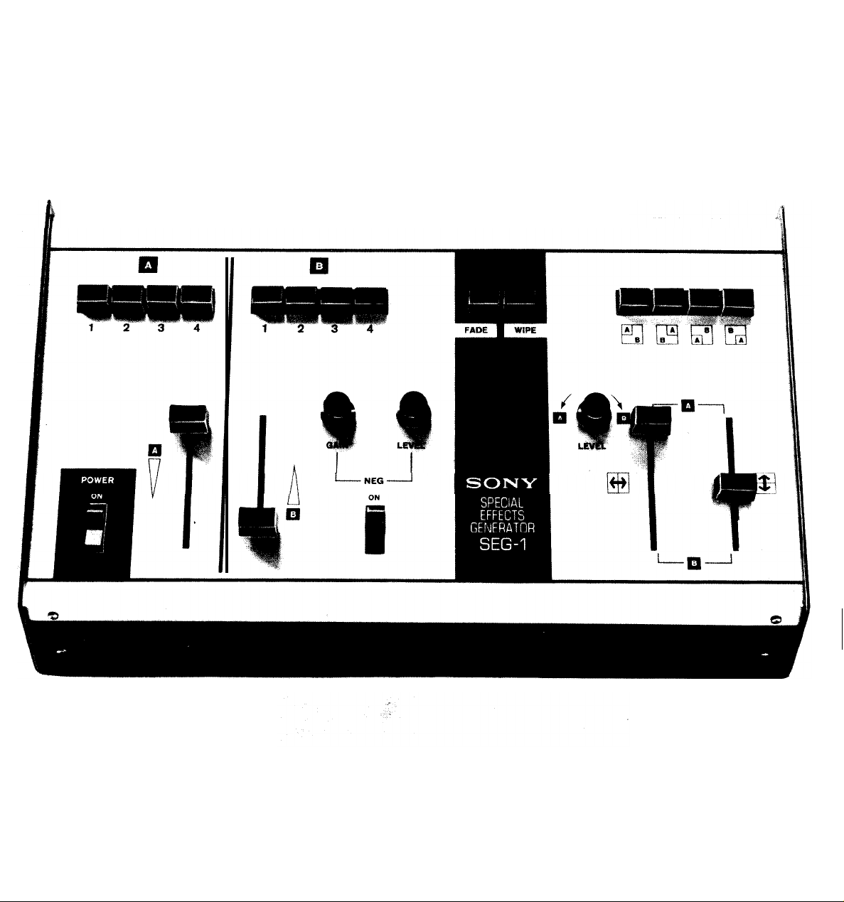
SPECIAL-EFFECTS
GENERATOR
SEG-1
2V990769-1
373-Printing
-NEG-
SONY CORPORATION OF AMERICA
4747 Van Dam Stnet, Long Island City, New York 11101
PRINTED IN
USA
Page 2

TABLE OF CONTENTS
General Description
Circuit Description
Transistor Voltage Chart.
Illustrations
...............................
.............................
..........................
. . . . . . . . . . . . . . . . . . . . . . . . . . . . .
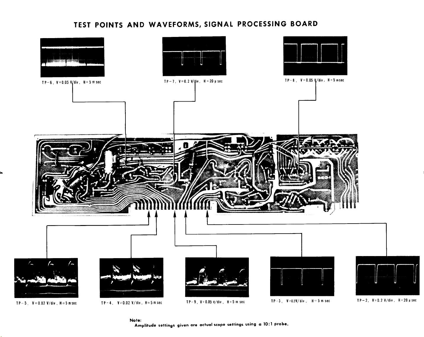
Test Points and Waveforms, Signal Processing Board.
Test Points and Waveforms, Sync Generator Board
Schematic Diagram, Signal Processing Board
Printed Circuit, Signal Processing Board
Schematic Diagram, Sync Generator Board
Printed Circuit, Sync Generator Board
Parts List
...............................
.................
................
..................
1
...........
.............
...............
1
3
4
4
5
6
7
8
9
10
Supplement
................................
13
Page 3
GENERAL DESCRIPTION
INTRODUCTION
SONY Model SEG-1 is a special-effects generator
with facilities for switching, fading, superimposing,
and wiping two video signals. Inputs accept up to
four SONY video cameras and provisions are included
to monitor the output of each camera.
may be inverted, if desired, to yield a negative picture. In addition, an internal sync generator supplies
2:l
interlace sync, or sync may be supplied from an
external source.
The SEG-1 may be used with any SONY video camera,
monitor, and/or Videocorder. Refer to the Owner’s
Instruction Manual for the complete operating procedure.
One channel
External sync:
Power requirements:
Power consumption:
Dimensions:
Weight:
Accepts vertical and hor-
izontal sync from
Series Videocorders or
vertical sync (-4V p-p)
from an external
sync generator. See pin
connections below.
117V, 60Hz 3-wire parallel
ground plug
7
watts
5
1/4" H
x 15 1/2" W x 10” D
8
½
lb.
CV-
2:l EIA
TECHNICAL SPECIFICATIONS
Camera video inputs:
Number of camera inputs:
Monitor video outputs:
Number of monitor outputs: 4, SO-239 UHF receptacle
Number of line outputs: 2, 1-Hirschmann 6 Pin
Internal sync:
1.0
-1.4V
7
5 n impedance.
must be supplied with
composite video.
4, Hirschmann 6 Pin
receptacle
1.0
upon input), sync negative,
75 Cl
2:l
SELECT switch is set to
INT.
p-p, sync neg.
-
1.4V p-p, (dependent
impedance
receptacle
1 -SO -239UHF
receptacle
interlace when SYNC
Input 1
CIRCUIT DESCRIPTION
,
VIDEO INPUT
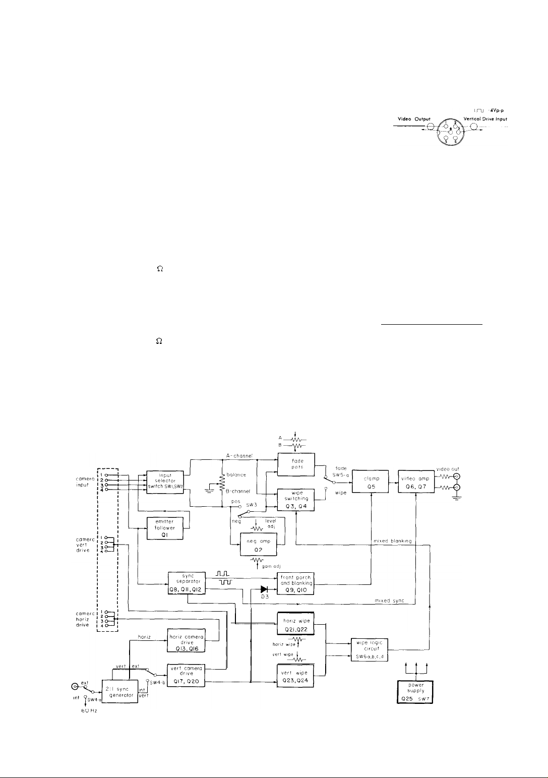
Figure 1 shows the block diagram of the SEG-1.
Up to four cameras, either 4 CV-Series or 4 DXC-Series
#l
#4.
To de-
must al-
Each cam-
source-
B-
can be driven through Hirschmann connectors.
velop the sync pulse in the SEG-1, Camera
ways be connected with composite video signals, while
either composite -- or non-composite -- video signal
is acceptable through Camera #2,
era output can be monitored through four (4)
terminated SO-239 UHF receptacles.
Any combination of input selector switches is
accepted.
Video signals are balanced between A- and
channel by potentiometer
A-&+
““r”-
VRl..
#3
and
If the output video
Fig. 1. Block Diagram of SEG-1
1
Page 4

levels of A- and B-channel cameras are very different, the camera lens f-stop should be readjusted.
VIDEO
one-stage amplifier, Q2, is employed in channel B.
Gain and level adjustments are accomplished by
VR2 and VR3 respectively.
positive picture can be obtained on channel B by
means of SW-3.
DISSOLVE
INVERTER
To produce a negative picture, an inverting
Either a negative or a
by the two wipe one-shots are manipulated by resistor-transistor-logic
gate IC-2 and switches SW-6 to arrange the vertical,
horizontal and corner wipes.
CLAMPING
The video signal selected by mode switch SW-5
is clamped to ground during blanking time by Q5.
The horizontal blanking pulse includes front and back
porch, while the vertical blanking pulse has only a
back porch.
(RTL)
inverters IC-1, RTL NOR
The two selected signals are independently
attenuated by dissolve potentiometers VR4 and
VR5, mixed by R24 and
the FADE position, presented to the video amplifier.
WIPES
When mode switch
analog gates Q3 and Q4 switch rapidly between
the two selected channels in accordance with the
logic signals on their bases. The switched video
signals are mixed by
are arranged so that whenever one transistor is
turned on (turning off its video signal), the other
is turned off. This guarantees that one channel
or the other feeds the monitor at all times.
WIPE LOGIC
The logic signals that control these transistors
are derived from the horizontal and vertical sync
pulses.
multivibrator
mined by the setting of the horizontal wipe pot VR6.
At one extreme, a transition between channels is
produced at the left side of the screen.
other pot extreme, a long
duced that delays the transition until the right
side of the screen.
slower (O-16 ms.
produces variable width pulses, triggered by the
vertical pulse, for horizontal direction wipes.
using in combination independently adjustable pots
VR6 (horizontal wipe) and VR7 (vertical wipe) and
wipe selector switch, SW-6, it is possible to obtain
four corner wipes, as well as vertical and horizontal wipes.
Each horizontal pulse triggers a one-shot
(Q21/Q22)
Vertical wipe pot
The variable-duration pulses produced
R25
and, with
SW5-a
is set to WIPE,
R27
and R28. Logic signals
whose 0” time is deter-
(60~µs)
VR7
does a similar job at a
)
rate: Vertical one-shot
SW5-a
At the
pulse is pro-
in
Q23/Q24,
By
The horizontal blanking pulse is developed from
Camera #l and is a composite video signal.
separator Q8 produces mixed sync, which is a positive going 6 volt pulse.
multivibrator (Q 9
about 2 µs in front of the sync pulse to form the front
porch.
The sync pulses are delayed by Cl6 to form the
horizontal back porch.
mixed sync, horizontal back porch and the vertical
blanking pulse are added with diodes Dl
mixed blanking.
transistor, Q5.
VIDEO AMPLIFIER
A two-stage feedback amplifier
employed as the final stage.
impedance to drive two
from Camera
video amplifier.
CAMERA DRIVE
Two modes of camera drive, external and
internal, are available.
one interlace sync generator is installed which is
phase locked to either incoming vertical pulses
(through a Hirschmann male receptacle) or to
internal 60 Hz line frequency.
After the sync generator, both the horizontal
and the vertical pulses are shaped by
and
Ql7
-Q20 respectively. These pulse-shaping
amplifiers can drive a 19 (75 + 4) ohm load with a
4-volt negative-going pulse.
Due to the phase difference of horizontal
driving pulses, a combination of DXC-Series and
CVC-Series cameras is not recommended.
This signal is sent to clamping
#l
is inserted at the output of the
By means of a one-shot
/Q10),
a
60-µs
delayed pulse occurs
The horizontal front porch,
(Q6/Q7)
This gives low output
75-ohm
lines.
In the SEG-1, a two-to-
Mixed sync
Q13 -Q16
-D3
to
is
Sync
give
Page 5
TRANSISTOR VOLTAGE CHART
SIGNAL PROCESSING BOARD
TRANSISTOR
Q1
Q2
Q3
Q4
Q5
Q6
Q7
Q8
Q9
QlO
Q11
Q12
Q13
Q14
Q15
Q16
Q17
Ql8
Q19
Q20
Q21
Q22
Q23
Q24
Q25
All voltages above measured with a 20,000 ohms-per-volt VOM.
B
2. 80
6. 90
0
0
0. 16
2.10
7.20
6. 20
0. 08
6.
70
0. 01
5. 50
0. 65
6. 60
6. 80
0. 32
0.10
0. 63
0. 08
6. 40
0. 08
7.10
0. 06
7. 0
8. 0
7. 60
0. 28
0. 05
0. 05
0. 75
7. 0
1.20
0. 45
5. 0
0. 73
5. 50
6. 10
0. 45
6. 80
0. 82
6. 40
6. 10
0. 28
6. 40
6. 80
2.40
4. 20
2. 05
3. 50
11. 0
C
L
E
2. 30
7. 60
0
0
0
1. 65
8. 0
6. 0
0
6. 0
0
4. 8
0
7.1
7.1
0
0
0
0
5. 90
0
7. 50
0
7. 60
7. 60
LOCATION *
c-4
E-3
F-2
F-2
H-2
J-2
J-2
c-5
c-5
E-5
F-4
G-4
C-6
C-6
D-6
E-6
C-8
C-8
D-7
E-7
G-6
G-5
G-8
G-8
L-4
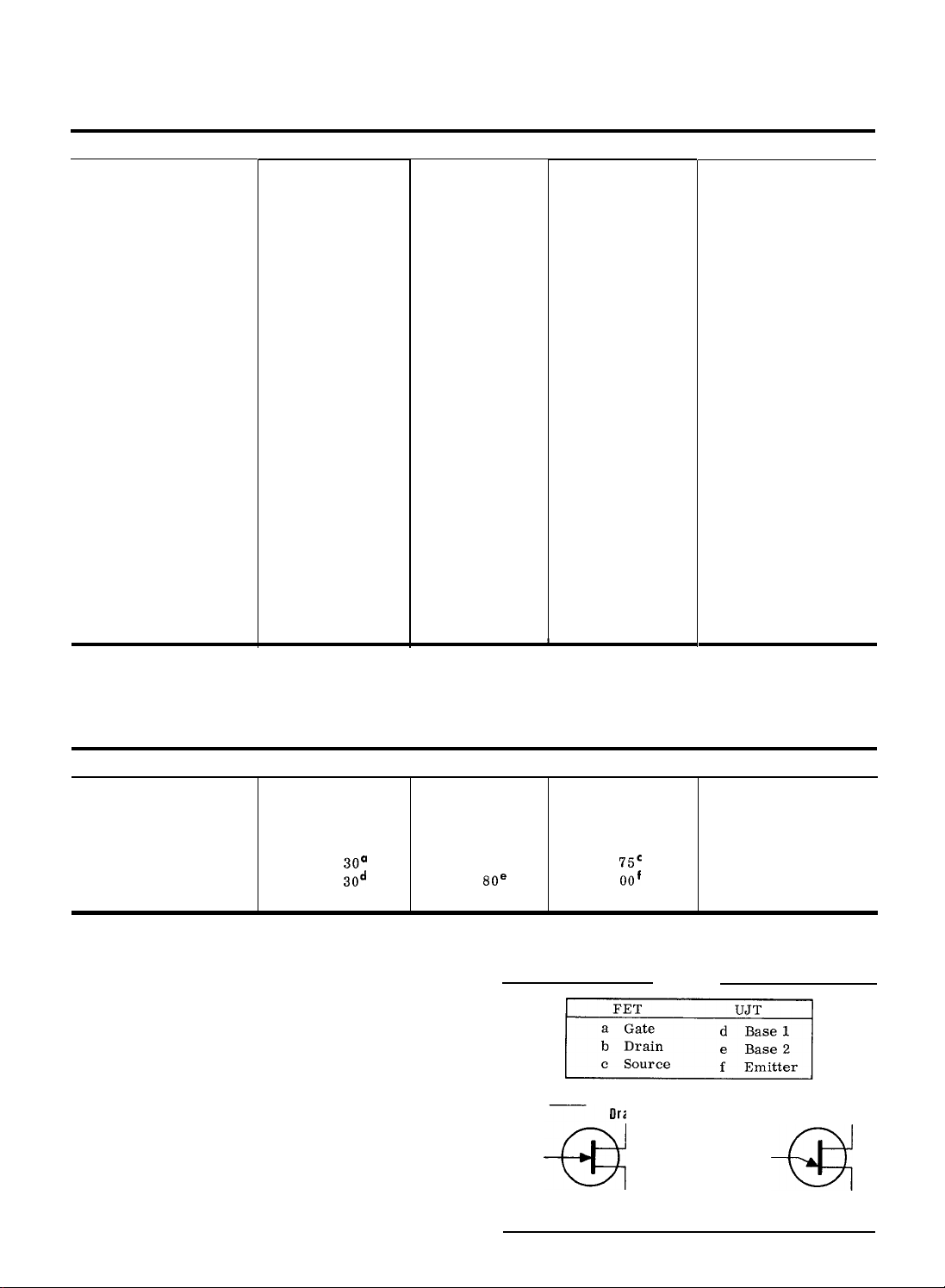
SYNC GENERATOR BOARD
TRANSISTOR
Q1
Q2
Q3
Q4
(FET)
Q5
(UJT)
B
-0.66
0.
66
0
5.
30°
0.
3od
All voltages above measured with a VTVM.
SEG-1 CONTROL SETTINGS:
Channel A Level Control = Maximum (upper position)
Channel B Level Control = Maximum (lower position)
LEVEL Control
FADE -WIPE Selector
SYNC SELECT Switch
*Refers to Schematic Diagram Coordinates
= Center
= Fade
= INT
C
0.
58
0.
55
58
0.
0..
58”
4.
80e
-1
FET
Gate
a
(
N-Type)
E
0
0
0. 55
1.
75c
oaf
3.
LOCA
B-2
c-2
D-2
D-2
E-2
TION*
NOTES:
UJT
Drain
Emitter
Source
a
Base 2
Base 1
3
Page 6
Page 7

Page 8

Page 9

Page 10

Page 11

Page 12

PARTS
LIST
MECHANICAL PARTS
No.
ASSEMBLED PARTS
Part Number
AS-SEG-l-l
AS-SEG-1-2
Description
Screw, Pan Head (+)
#4-40 x
Clear Mylar Washer #4
Front Panel
Switch Mounting Bracket
Screw, Pan Head (+)
#6-32x
Clear Mylar Washers
Speed Nut, Tinnerman
#C8936-632
Speed Nut,
#C-7795-440-1
Pal
Screw,
#4-40 x
Speed Nut, Tinnerman
#C-8022-632-27
PalNut #4-40
Rubber
Bottom Assembly,
Top Cover Assembly
Knobs for Pushbutton
Switch
Knobs for Slide Switch
Knobs for Rotating Pots
Standoff
Description
Signal Processing Board,with com-
ponents and switchbracket
Sync Generator Board,
ponents.
l/4
3/8
Nut,
Reg. Type
Flat
3/4
Bumper #4076
Tinnerman
Head
(+)
#4
#4-40
SIGNAL PROCESSING BOARD
RESISTORS
All resistors are
noted.
Symbol
Rl
R2
R3
R4
R5 RlK-l/4-10C
R6
R7
R8
R9 RlOK-l/4-10C
Rl0 R6.8K-l/4-10C
Rll R680-l/4-10C
R12
R13
R14
R15
R16 R6.8K-l/4-10C
l/4
watt,
10%
unless otherwise
Part No.
R82-l/4-10C
" "
" "
" "
"
" "
" "
R220-l/4-10C
" "
" "
"
Description
820hms
lk
10k
6. 8
680
220
6.8 k
12
12
14
with com-
"
k
"
'ty.
4
8
4
4
4
4
4
1
1
4
3
8
Symbol
R17
R18
R19
R20
R21
R22
R23
R24
R25
R26
R27
R28
R29
R30
R31
R32
R33
R34
R35
R36
R37
R38
R39
R40
R41
R42
R43
R44
R45
R46
R47
R48
R49
R50
R51
R52
R53
R54
R55
R56
R57
R58
R59
R60
R61
R62
R63
R64
R65
R66
R67
R68
R69
R70
R71
R72
R73
R74
R75
R76
R77
R78
Part No.
R1.5K-l/4-10C
Rl0K-l/4-1OC
"
R560-l/4-10C
R18K-l/4-10C
R180-l/4-10C
RlK-l/4-1OC
R3.3K-l/4-10C
"
RlK-l/4-1OC
R1.5K-l/4-10C
"
R6.8K-l/4-10C
R33K-l/4-10C
R18K-l/4-10C
R2.2K-l/4-10C
"
R4.7K-l/4-10C
R3.3K-l/4-10C
R68-l/4-10C
R3.3K-l/4-10C
RlK-l/4-1OC
R68-l/4-10C
"
R820-l/4-10C
"
R220K-l/4-10C
R1.5K-l/4-10C
RlOK-l/4-1OC
R3.3K-l/4-10C
R4.7K-l/4-10C
R68K-l/4-10C
R2.2K-l/4-10C
R82-l/4-10C
RlOK-l/4-1OC
R3.3K-l/4-10C
R560-l/4-10C
R2.2K-l/4-10C
R680-l/4-10C
RlK-l/4-1OC
R33K-l/4-10C
RlOK-l/4-10C
R56K-l/4-10C
R4.7K-l/4-10C
R2.2K-l/4-10C
R560-l/4-10C
R680-l/4-1OC
RlOO-l/4-10C
R47-l/4-10C
R4.7K-l/4-10C
"
R3.3K-l/4-10C
R18K-l/4-10C
R680-l/4-10C
R2.2K-l/4-10C
R560-l/4-10C
R47-l/4-10C
RlOK-l/4-1OC
R6.8K-l/4-10C
R220-l/4-10C
" "
Description
1. 5 k
10k
"
560
18 k
180
lk
3.3 k
"
lk
1. 5 k
"
6. 8 k
33 k
18 k
2. 2 k
"
4.7 k
3.3 k
68
3. 3 k
lk
68
"
820
"
220k
1.5 k
10k
3.3 k
4.7 k
68 k
2. 2 k
82
10k
3.3 k
560
2. 2 k
680
lk
33 k
10k
56k
4.7 k
2.2 k
560
680
100
47
4.7 k
"
3.3 k
18 k
680
2. 2 k
560
47
10k
6.8 k
220
10
Page 13

Symbol
Part No.
Description
R79
R80
R81
R82
R83
R84
R85
R86
R87
R88
R89
R90
R91
R92
R93
R68K-l/4-10C
Rl OK-1/4-l
R82-l/4-10C
R3.3K-1/4-l
R220-l/4-10C
RlOK-l/4-1OC
Rl8K-l/4-10C
Rl2OK-l/4-IOC
RlOK-l/4-1OC
R3.
3K-l/4-10C
R82-l/4-10C
R150-l/4-10C
OC
"
"
"
OC
CAPACITORS
All capacitors are electrolytic,
otherwise noted
Cl
c2
C3
C4
C5
C6
C7
C8
C9
Cl0
Cl1
Cl2
Cl3
Cl4
Cl5
C16
Cl7
Cl8
Cl9
C20
C21
c22
c23
C24
c25
C26
C27
C28
C
2 9
C3O
C3 1
C32
3
C3
ClOOM-15-20E
"
"
"
"
"
"
"
"
C5M-15-20E
C390-3-20E
ClOOM-15-20E
C5M-15-20E
co.
00lM-600-10MY
ClOOM-15-20E
ClOOP-600-1OC
CO.
OOlM-15-10E
ClOOM-15-20E
C27OP-15-20C
CO.OlM-15-20C
ClOOM-15-20E
CO.
05M-25-20C
ClOO-15-20E
"
CO.
0015M-600-10MY
Cl00M-15-20E
CO.
22-600-1OMY
ClOOM-15-20E
CO.
OlM-12-20E
C3000M-15-20E
Cl
00M
-15 -2 OE
"
TRANSISTORS
Q1
Q2
Q3
Q4
TR-2N4123
TR-2N3906
TR-2N3646
"
20%,
unless
68 k
10 k
82
3. 3k
220
"
10 k
18 k
120 k
10 k
3.3 k
82
"
150
"
lOOµF,
15WV
"
"
"
"
"
"
"
"
5µF, 15WV
390µF,
3WV
l00µF, 15WV
5µF,
15WV
0.001 mylar
6OOWV,lO%
lOOµF,15WV
lOOpF,
ceramic
10%
0.
OOlµF,
ceramic
10%
lOOµF,15WV
270pF,
ceramic
20%
0.
OlµF,
ceramic
20%
lOOµF,l5WV
0.
05µF,
ceramic
20%
lOOµF,
15wv
"
0.
0015µF,
lOOµF, 15WV
0.22µF,
lOOµF, 15WV
0.
0lµF, 12WV
3000µF, 15WV
lOOµF, 15WV
"
"
2N4123
2N3906
2N3646
"
600WV
mylar, lO%
Q5
Q6
Q7
Q8
Q9
Q10
Q11
Q12
Q13
Q14
Q15
Ql6
Q17
Q18
Q19
Q20
Q21
Q22
Q23
Q24
Q25
TR-2N4123
"
TR-2N3906
"
TR-2N4123
TR-2N3906
TR-2N4123
"
"
TR-2N3906
"
TR-2N4123
"
"
"
"
"
TR-2N3906
TR-2N4123
TR-2N3906
TR -2N3053
INTEGRATED CIRCUITS
IC-1 IC-MC714
IC-2 IC-MC789
POTENTIOMETERS
VRl
VR2
VR3
VR4
VR5
VR6
VR7
VR8
VR9
P-2.
5K-2-BW
"
"
SP-lK-l-BW
"
"
"
TP-lOK-l/4-BC
"
DIODES
Dl
D2
D3
D4
D5
D6
D7 D-lN4002
D8
D9
DlO
Dll
D-lN914
"
"
"
"
"
"
D-lN914
"
2D-lN5235
SWITCHES
SW-1
SW-2
SW-3
SW-4
SW-5
SW-6
SW-7
PSW-4-16PDT
PSW-4-16PDT
SLSW-l-DPDT
"
PSW-2-6PDT
PSW-4-16PDT
SLSW-l-DPDT-NE
2N4123
"
2N3906
2N4123
2N3906
2N4123
2N3906
2N4123
"
2N3906
2N4123
2N3906
2N3053
MC
714, Dual
Nor Gate
MC 789, Hex
Inverter
2.5k
"
1 k, Slide Pot.
"
"
"
lOk
"
lN914
"
"
"
"
lN4002
"
lN914
"
lN5235
4 section pushbutton
"
DPDT (black) Slide
switch
DPDT Slide switch
2 section pushbutton
3PDT/section
4 section pushbutton
4PDT/section
DPDT with Red
Neon Lamp
Page 14

Symbol Part No. Description
CONNECTORS
CN
1,2,
3, 4
CN
6,7,
8, 9
CN 10
CN
11
CN 12
CN 13
CN-SO239
CN-MAB6
CN-MASE16
CN-4823’79-9
CN-582370-9
CN-582375-9
Coaxial Receptacles
Hirschmann 6 pin
Hirschmann 6 pin
AMP Edge Connector,
AMP Edge Connector,
AMP Edge Connector,
female Receptacles
male Receptacles
22 pin
5 pin
4 pin
MISCELLANEOUS
Tl
CD 1
CTS 1
PT-96-P-3
TS-3008
Power Transformer,
l0VCT, l
AC Power Cord
8P Terminal Strips
#3008
A
SYNC GENERATOR BOARD
RESISTORS
Rl
R2
R3
R4
R5
R6
R7
R8
R9
RlO
Rll
R12
R12
R14
R15
R16
R17
R18
R19
R4.
7K-l/4-10C
R18K-l/4-10C
R4.
7K-l/4-10C
RlK-l/4-1OC
R33K-l/3-10C
Rl 0K-1/4-l
R3.3K-l/4-10C
RlOK-l/4-1OC
R120K-l/4-10C
Rl. 5K-l/4-10C
R680-l/4-10C
R330-l/4-10C
RlOK-l/4-1OC
R18K-l/4-10C
R150-l/4-10C
R220-l/4-10C
R20-5-10W
R18K-l/4-10C
OC
"
4.7 k
18kR
4.7k
1k
33 k
10k
3.3k
1Ok
"
120k
1.5k
680
R
330 R
1Ok
18k
150 R
220
R
20 R, 5 Watt,
wire wound
18k
C6
C7
C8
C9 C470P-400-10C
Cl0 co.
Cl1
Cl2
C25M-25-20E
ClOOOP-400-10MY
ClOOM-15-20E
2-12-20C
CO.
05M-12-20C
CO.
lM-12-20C
DIODES
Dl
D2
ZD-lN4729
ZD-lN5232 lN5232
TRANSISTORS
Q1
Q2
Q3
Q4
Q5
TR-lN4123
"
"
FET-2N5484 2N5484(FET)
UJT-2N4870
INTEGRATED CIRCUITS
IC-1 IC-MC790
IC-2
IC-3
IC-4
IC-5
IC-6
IC-7 IC-MC724
IC-8 IC-MC799
"
"
"
"
"
25µF,25WV
lOOOpF,400WV,
10%,
mylar
lOOµF,
15WV
470pF, 400WV
10%,
ceramic
0.2µF, 12WV,
20%, ceramic
0.
05µF,
12WV,
20%,
ceramic
O.lµF,12WV,
20%,
ceramic
lN4729
2N4123
"
"
2N4870
MC790(Dual J-K Flip
"
"
"
"
MC724 (Quad 2 Input
Nand/Nor Gate
MC799 (Dual Buffer)
Flop)
POTENTIOMETER
VR-1 TPlOK
CAPACITORS
CO.
Cl
c2
c3
c4
c5
lM-12-20C
02M-12-20C
co.
C5M-25-20E
CO.
lM-12-20C
CO.
OlM-12-20C
l/4-10BC
1Ok
O.lµF,12WV,
20%,
ceramic
0. 02µF, 12WV
20%,
ceramic
5µF, 25WV
0.
lµF,
12WV
20%,
ceramic
0. 0lµF, 12WV
20%,
ceramic
12
Page 15

SUPPLEMENT
The following changes are incorporated into all SEG-1 Special-Effects Generators bearing
Serial No. 1523 and higher.
accommodate these changes. Refer to the revised schematic diagram and the SEG-1 Service Manual.
From Serial No. 2000 and higher, the Signal Processing Board has been redesigned as a
two-sided printed board. The Sync Generator Board has undergone minor changes in.
printed design as of the same serial number, and chassis modifications have been performed accordingly.
Minor modifications have been made to the circuit boards to
Details of the changes are given in the table below.
to the schematic diagrams.
SIGNAL PROCESSING BOARD
Symbol
Cl9
c22
Q26
R30
R32
R49
R79
R8-7
R94
R95
VR8
VR9
VRlO
VRll
Old Value New Value New Part No.
270
pF
.
05µF
33k
2.2k
68kR
68kR
120kR
10k
lOk
150
pF
.
02µF
2N5485
82OR
56k
56k
1OOk
68k
lk
25k
25k
25k
25k
C15OP-400-20C
CO. 02M-25-20C
FET2N5485
R820-l/4-10C
R56K-l/4-10C
R56K-1/4-l
Rl
OOK-1/4-l OC
R68K-1/4-l
RlK-l/4-1OC
TP-25-l/4-BC
TP-25-l/4-BC
TP-25-l/4-BC
TP-25-l/4-BC
Symbols and area coordinates refer
Remarks Location
OC
OC
Changed
"
Added
Deleted
Changed
"
"
"
Added
Added
Changed
"
Added
"
C-6
C-8
H-2
G-l
H-2
D-5
G-6
G-8
H-2
H-2
D-5
H-2
G-6
G-8
SYNC GENERATOR BOARD *
Symbol
c4
Cl3
IC-6
Q6
R5
R7
R16
R20
Old Value New Value
02µF
O.lµF
33k
3.3k
15OR
.
01
.
MC790
2N4123
47k
10k
lk
10k
µF
New Part No.
CO. 02M-15-20C
CO. OlM-15-20C
IC-MC790
TR2N4123
R47K-1/4-l
Rl OK-1/4-l
RlK-1/4-l
Rl OK-1/4-l
OC
OC
OC
OC
*Modification recommended to older units.
13
Remarks Location
Changed
Added
l/2
section
Added
Added
Changed
"
"
Added
c-2
c-2
A-3
c-2
c-2
D-2
B-3
c-2
Page 16

Page 17

Page 18

Page 19

Page 20

The following list contains stock numbers for cabinet parts and hardware.
to the SEG-1 Service Manual for a complete list of electrical parts.
MECHANICAL PARTS
Refer
Part No.
DWG-V-218-1
-2
-3
-4
-7
-8
-9
-11
-12
-13
-14
-15
-18
-20
-21
-22
-23
-24
-25
-26
-27
-28
-29
-30
Screw, Pan Head (+)
#4-40
Clear Mylar Washer
Front Panel
Switch Mounting Bracket
Screw, Pan Head
(+) #6-32 x
Clear Mylar Washer
Speed Nut, Tinnerman
# C8936-632
Speed Nut, Tinnerman
#C-7795-440-1
Pal Nut, Reg. Type
#
4-40
Screw, Flat Head
(+)
# 4-40 x
Speed Nut, Tinnerman
# C-8022-632 -27
Pal Nut #4-40
Rubber Bumper # 4076
Bottom Assembly
Top Cover Assembly
Knob for Pushbutton
Switch
Knob for Slide Switch
Knob for Rotating Pots
Standoff
Screw, Flat Head
(-) #4-40 x
Sync Board Screw
(+)
#4-40 x
Power Cord Strain
Relief Bushing
Screw, Flat Head
(+) #
Screw, Flat Head
(+) # 6-32 x
Description
x
l/4
4-40 x
3/8
3/4
3/16
3/4
l/2
l/4
#4
#4
Q'ty
4
8
4
12
4
4
4
12
4
1
1
14
4
1
4
8
 Loading...