

Page 1
AIT Drive
User’s Guide
2-108-088-11(1)
AIT-3 TAPE DRIVE
SDX-700V Series
2004 Sony Corporation
Page 2
This document contains proprietary
information which is protected by
copyright.
All rights reserved. No part of this
document may be photocopied,
reproduced or translated to another
language without prior written consent
of Sony.
The information contained in this
document is subject to change without
notice.
SONY MAKES NO WARRANTY
OF ANY KIND WITH REGARD TO
THIS DOCUMENT.
Sony shall not be liable for errors
contained herein, indirect, special,
incidental or consequential damages in
connection with the furnishing,
performance or use of this document.
Your AIT TAPE DRIVE is assigned a
Model No. ATDNA3 for regulatory
compliance certifications.
The number is indicated on the model
number label on your drive along with
the rated voltoge and current.
VORSICHT
Diese Ausrüstung erfüllt die
Europäischen EMC-Bestimmungen für
die Verwendung in folgender /
folgenden Umgebung(en):
• Wohngegenden
• Gewerbegebiete
• Leichtindustriegebiete
(Diese Ausrüstung erfüllt die
Bestimmungen der Norm EN55022,
Klasse B.)
2
Page 3

IMPORTANT SAFEGUARDS
For your protection, please read these
safety instructions completely before
operating the appliance, and keep this
manual for future reference.
Carefully observe all warnings,
precautions and instructions on the
appliance, or the one described in the
operating instructions and adhere to
them.
USE
Power Sources – This unit should be
operated only from the type of power
source indicated on the marking label.
If you are not sure of the type of
electrical power, consult your dealer or
local power company.
For the unit with a three-wire
grounding type ac plug:
If you are unable to insert the plug into
the outlet, contact your electrician to
have a suitable plug installed. Do not
defeat the safety purpose of the
grounding plug.
AC Power cord: (for AC mains
operating unit only)
The AC power cord should have
appropriate safety approvals or
marking for the country in which the
equipment will be used. Consult your
dealer or local power company.
Cleaning – Unplug the unit from the
wall outlet before cleaning or
polishing it. Do not use liquid
cleaners or aerosol cleaners.
Use a cloth lightly dampened with
water for cleaning the exterior of the
unit.
Object and Liquid Entry – Never
push objects of any kind into the unit
through openings as they may touch
dangerous voltage points or short out
parts that could result in a fire or
electric shock. Never spill liquid of
any kind on the unit.
3
Page 4

INSTALLATION
Water and Moisture – Do not use
power-line operated units near water for example, near a bathtub,
washbowl, kitchen sink, or laundry
tub, in a wet basement, or near a
swimming pool, etc.
Power-Cord Protection – Route the
power cord so that it is not likely to be
walked on or pinched by items placed
upon or against them, paying
particular attention to the plugs,
receptacles, and the point where the
cord exits from the appliance.
Accessories – Do not place the unit on
an unstable cart, stand, tripod, bracket,
or table. The unit may fall, causing
serious injury to a child or an adult,
and serious damage to the unit. Use
only a cart stand tripod, bracket, or
table recommended by the
manufacturer.
Ventilation – The slots and openings
in the cabinet are provided for
necessary ventilation. To ensure
reliable operation of the unit, and to
protect it from overheating, these slots
and openings must never be blocked or
covered.
• Never cover the slots and openings
with a cloth or other materials.
• Never block the slots and openings
by placing the unit on a bed, sofa,
rug or other similar surface.
• Never place the unit in a confined
space, such as a bookcase, or builtin cabinet, unless proper ventilation
is provided.
SERVICE
Damage Requiring Service – Unplug
the unit from the wall outlet and refer
servicing to qualified service
personnel under the following
conditions:
• When the power cord or plug is
damaged or frayed.
• If liquid has been spilled or objects
have fallen into the unit.
• If the unit has been exposed to rain
or water.
• If the unit has been subject to
excessive shock by being dropped,
or the cabinet has been damaged.
• If the unit does not operate normally
when following the operating
instructions. Adjust only those
controls that are specified in the
operating instructions. Improper
adjustment of other controls may
result in damage and will often
require extensive work by a
qualified technician to restore the
unit to normal operation.
• When the unit exhibits a distinct
change in performance - this
indicates a need for service.
Servicing – Do not attempt to service
the unit yourself as opening or
removing covers may expose you to
dangerous voltage or other hazards.
Refer to all servicing to qualified
service personnel.
4
Page 5

Table of Contents
Overview ..................................................................................................................6
Introduction ..............................................................................................................7
About AIT Drives ............................................................................................ 7
Precautions .......................................................................................................8
Installation ..............................................................................................................10
SCSI Connection/Setting the SCSI ID ...........................................................10
Option Switches (DIP Switch) ....................................................................... 11
Mounting Holes..............................................................................................14
Reconfiguring from 5.25" Model to 3.5" Model............................................15
Orientation......................................................................................................16
Attaching and Removing the Dust Cover............................................................... 17
Attaching the Dust Cover............................................................................... 17
Removing the Dust Cover .............................................................................. 19
Operation ................................................................................................................20
Location of 3 LEDs ........................................................................................ 20
Drive Operation.............................................................................................. 21
Emergency Tape Removal Procedure ............................................................ 23
WORM Function .................................................................................................... 25
Interface Implementation........................................................................................27
Supported SCSI Messages .............................................................................27
Supported SCSI Commands........................................................................... 27
Specifications ......................................................................................................... 28
Product Specifications.................................................................................... 28
Sony Contacts ......................................................................................................... 30
5
Page 6

Overview
The Sony SDX-700V series drives are high capacity data storage devices
using Advanced Intelligent tape (AIT) technology. The SDX-700V series
drives achieve high data reliability through Read-After-Write, an additional
level of Error Correction Code, and other features.
The Sony SDX-700V series drives store data on tape using standard
formats called AIT (Advanced Intelligent Tape) and ALDC.
6
Page 7

Introduction
About AIT Drives
SDX-700V series drives are internal AIT drive units that use data cartridges
conforming to the AIT-3 format. SDX-700V series drives support AIT-1,
AIT-2, and AIT-3 formats.
Features
The SDX-700V series drives have the following features:
• Support reading and writing to data cartridges conforming to the AIT-1,
AIT-2, and AIT-3 formats.
• The Read After Write Function and third-level error correction code
guarantee high data reliability.
• Data compression provides 260 gigabytes of storage on 230 m tapelength cartridge.
The native capacity is 100 gigabytes of storage on 230 m tape-length
cartridge.
• Stored data is automatically checked for compression.
• Ultra 160 Wide SCSI LVD/SE interface is fully supported for host
computer access.
*1
This is assuming 2.6 : 1 compression ratio.
The degree of data compression attained while recording data varies according to
system environment and data type.
*1
7
Page 8

Precautions
Installation
Avoid placing the drives in locations subject to:
– high humidity
– high temperature
– mechanical shock and vibration
– direct sunlight
*
For details, see “Specifications” on page 28.
Operation
• Do not move the drives while they are operating. It may cause
malfunctions.
• Avoid exposing the drives to sudden changes from a low to high
temperatures. This may cause water condensation to collect inside the
drives. If the ambient temperature should suddenly rise while the drives
are turned on, wait at least one hour before turning on the drives. If you
attempt to operate the drives immediately after a sudden increase in
temperature, malfunctions may occur.
• Turning off the power to the drives while they are writing to tape may
cause the tape to become unreadable. All previously negotiated
parameters will be lost, whenever power to the drives is cycled.
Transportation
• Keep the original packing materials to facilitate safe transportation of the
drives.
• Always remove the tape/media cartridge before moving the drives. After
removing the drives from the computer, repack them into their original
packing.
8
Page 9
Useable Cartridges
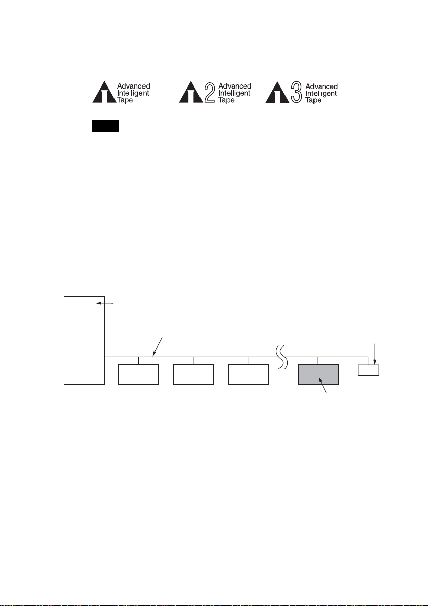
SDX-700V series can be used with data cartridges marked with the AIT-1,
AIT-2 or AIT-3 logo.
Note
Be sure to use only data cartridges designed specifically for AIT (do not use 8 mm video
cartridges) as this may damage the drives.
SCSI Termination
The SDX-700V series drives conform to the Microsoft PC97 standard,
which requires the internal (naked) drive to be terminated with an external
terminator.
Microsoft PC97 SCSI requirements
SCSI peripherals must not terminate the bus. Both internal and external cable ends are
instead terminated by plug-in connectors.
Host Computer Wide SCSI
68-pin cable
Terminator
SDX-700 series drive
Example of SCSI setup
9
Page 10
Installation
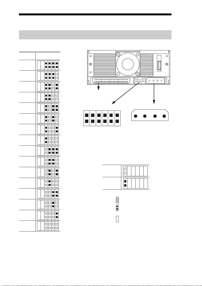
SCSI Connection/Setting the SCSI ID
SCSI ID
210
SCSI ID
0
1
2
3
P.D.
N.C.
3
SCSI 68pin Connector
4
Jumpers
Power Connector
5
5 V
6
7
SCSI ID 3
SCSI ID 2
SCSI ID 1
SCSI ID 0
10
1
8
9
1
Parity Disable
No Connection
Parity
Disable
Enable
12
13
Note :
14
= CLOSED/Jumper
OPEN/Jumper not
=
installed
=
t care
Don’
15
Parity Disable Jumper
Parity check function can be disabled by Jumper. Parity check is disabled
while left end jumper is installed. Parity generate function is always
enabled.
1234
GND GND 12 V
10
Page 11
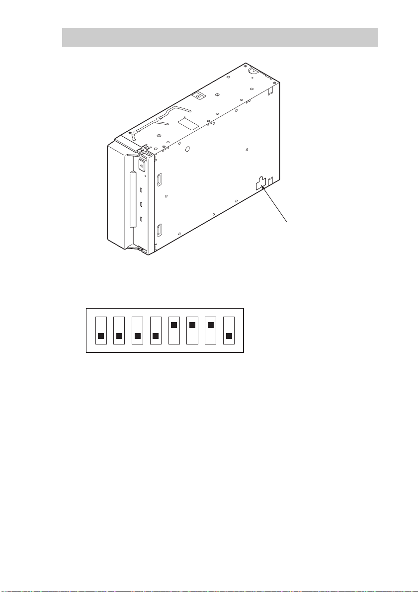
Option Switches (DIP Switch)
DIP Switch Positions
Default
ON
OFF
12345678
DIP Switch
1 Drive Mode (OFF)
2 Drive Mode (OFF)
3 Drive Mode (OFF)
4 Drive Mode (OFF)
5 Terminator Power (ON)
6 Periodic Cleaning Req (ON)
7 DC Control (1) (ON)
8 DC Control (2) (OFF)
11
Page 12
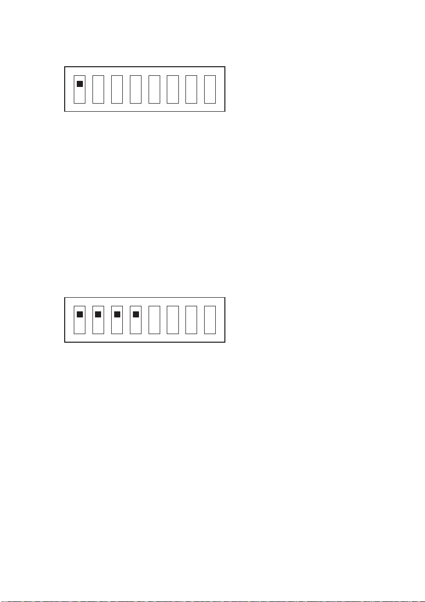
DR (Disaster Recovery*) Mode
To enable DR Mode, set position 1 [Drive Mode] switch to ON.
1 Drive Mode (ON)
ON
OFF
12345678
*
In Disaster Recovery Mode, an SDX-700 series drive enters the DR
2 Drive Mode
3 Drive Mode
4 Drive Mode
5 Terminator Power
6 Periodic Cleaning Req
7 DC Control (1)
8 DC Control (2)
Standby Mode 15 seconds after you insert a write-protected tape into the
drive, and all the drive LED blink. If you restart the drive while the LED
are blinking, it starts as a CD-ROM device.
For details about the Disaster Recovery Mode, refer to the instruction
manual that came with the application software you are using.
Emulation Mode
*
To enable Emulation Mode, set position 1 - 4 [Drive Mode] switches to
ON.
1 Drive Mode (ON)
ON
OFF
12345678
*
Emulation Mode returns the following in the Product Identification field
2 Drive Mode (ON)
3 Drive Mode (ON)
4 Drive Mode (ON)
5 Terminator Power
6 Periodic Cleaning Req
7 DC Control (1)
8 DC Control (2)
of Inquiry of a SDX-700V series drive.
SDX-700C
Data Compression Control DIP switch
Data compression can be selected by DIP switches. Data compression is
enabled while position 7 [DC Control (1)] is ON. Control by host can be
disabled when position 8 [DC Control (2)] is ON.
12
Page 13
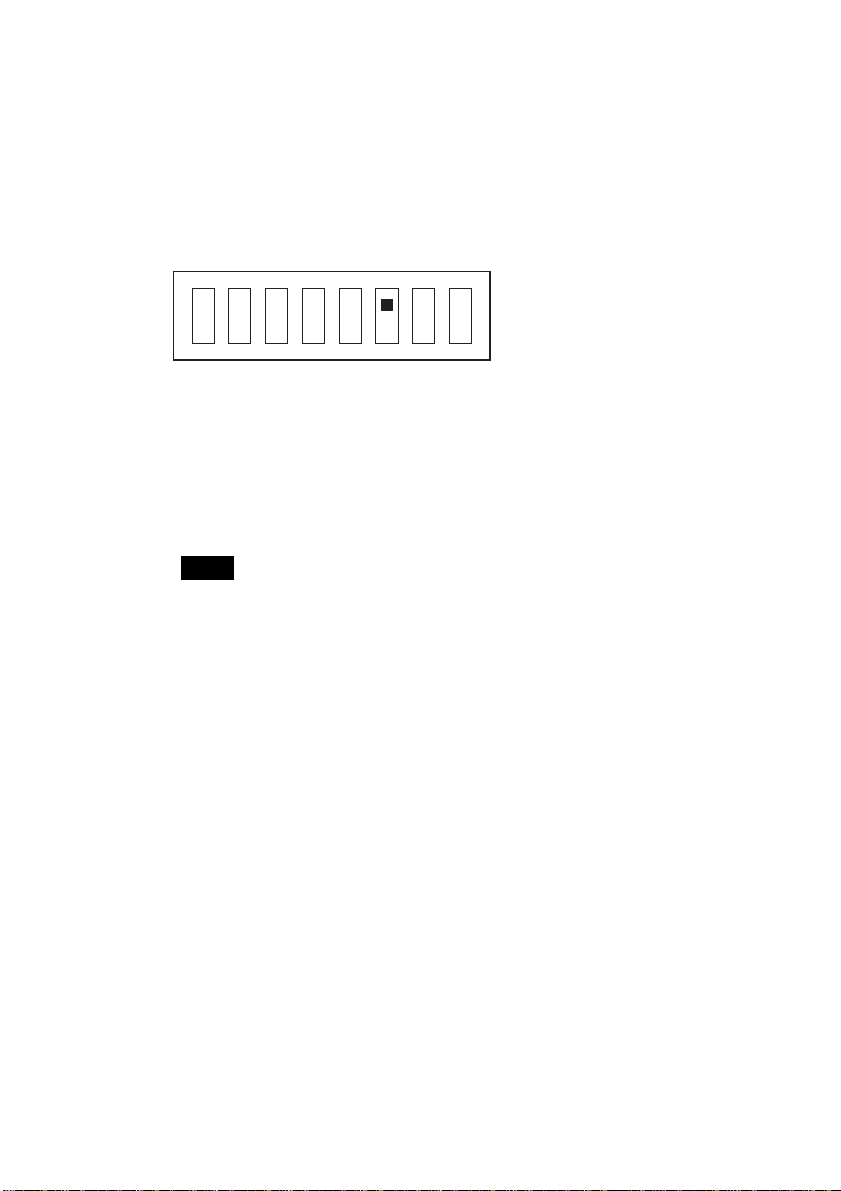
Terminator Power Control DIP switch
This DIP switch determines whether terminator power is supplied to the
SCSI bus. To enable terminator power, set position 5 [Terminator Power]
switch to ON.
Cleaning Request Mode
Periodic cleaning requests can be enabled by a DIP switch.
1 Drive Mode
ON
OFF
12345678
When switch 6 is ON, cleaning requests are enabled. When enabled, the
“CLEANING REQUEST” LED on the front panel lights after every 100
hours of operation.
When this LED lights, clean the drive with a head cleaning cartridge.
Note
To maintain the drive in optimum condition in environments affected by dust and other
contaminants, we recommend keeping cleaning requests enabled.
2 Drive Mode
3 Drive Mode
4 Drive Mode
5 Terminatore Power
6 Periodic Cleaning Req (ON)
7 DC Control (1)
8 DC Control (2)
13
Page 14
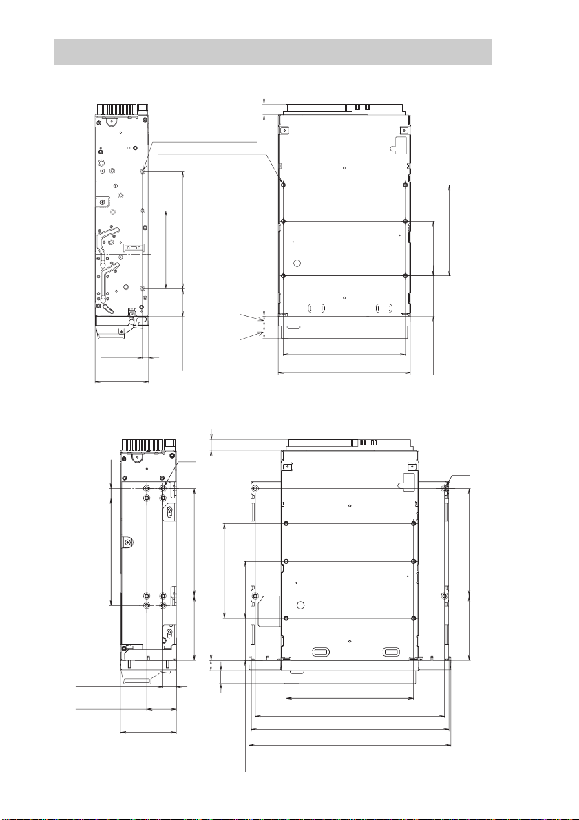
Mounting Holes
For 3.5" Standard Height
_
+
7.6 0.5 mm [0.3" 0.02"]
6-M3 (depth 2.5mm [0.10"] max.)
6-M3 (depth 2.5mm [0.10"] max.)
_
+
_
+
_
+
_
+
90.0 0.3mm [3.54" 0.01"]
60.0 0.3mm
[2.36" 0.01"]
_
+
4.8 0.5mm
_
+
[0.19" 0.02"]
_
+
41.2 0.5mm
_
+
[1.62" 0.02"]
For 5.25" Half Height
_
+
_
+
21.0 0.3mm
[0.83" 0.01"]
7.6 0.5 mm [0.3" 0.02"]
_
+
_
+
_
+
155.0 0.5mm [6.10" 0.02"]
_
+
_
+
7.4 0.6mm [0.29" 0.02"]
_
+
_
+
9.8 0.6 mm
[0.39" 0.02"]
_
+
_
+
_
+
94.0 0.5mm [3.70" 0.02"]
_
+
101.6 0.5mm [4.00" 0.02"]
_
+
_
+
_
+
_
+
_
+
_
+
42.0 0.3mm
[1.65" 0.01"]
70.0 0.3mm [2.76" 0.01"]
_
+
_
+
31.0 0.3mm
[1.22" 0.01"]
14
7.0mm
[0.28"]
_
+
_
+
79.2 0.3mm [3.12" 0.01"]
_
+
9.9 0.5mm
_
[0.39" 0.02"]
+
_
+
21.8 0.5mm
_
+
[0.86" 0.02"]
_
+
41.2 0.5mm
_
+
[1.62" 0.02"]
6-M3
_
+
_
+
_
+
_
+
_
+
79.2 0.3mm [3.12" 0.01"]
_
+
_
+
47.5 0.3mm
[1.87" 0.01"]
_
+
_
+
_
+
155.0 0.5mm [6.10" 0.02"]
42.0 0.3mm
[1.65" 0.01"]
70.0 0.3mm [2.76" 0.01"]
_
+
_
+
_
+
_
+
9.8 0.6 mm
[0.39" 0.02"]
_
+
7.4 0.6mm [0.29" 0.02"]
_
+
31.0 0.3mm [1.22" 0.01"]
_
+
94.0 0.5mm [3.70" 0.02"]
_
+
139.6 0.5mm [5.50" 0.02"]
_
+
146.0 0.5mm [5.75" 0.02"]
_
+
149.0 0.5mm [5.87" 0.02"]
_
+
_
+
_
+
_
+
4-M3
_
+
_
+
79.2 0.3mm [3.12" 0.01"]
_
+
_
+
47.5 0.3mm
[1.87" 0.01"]
Page 15
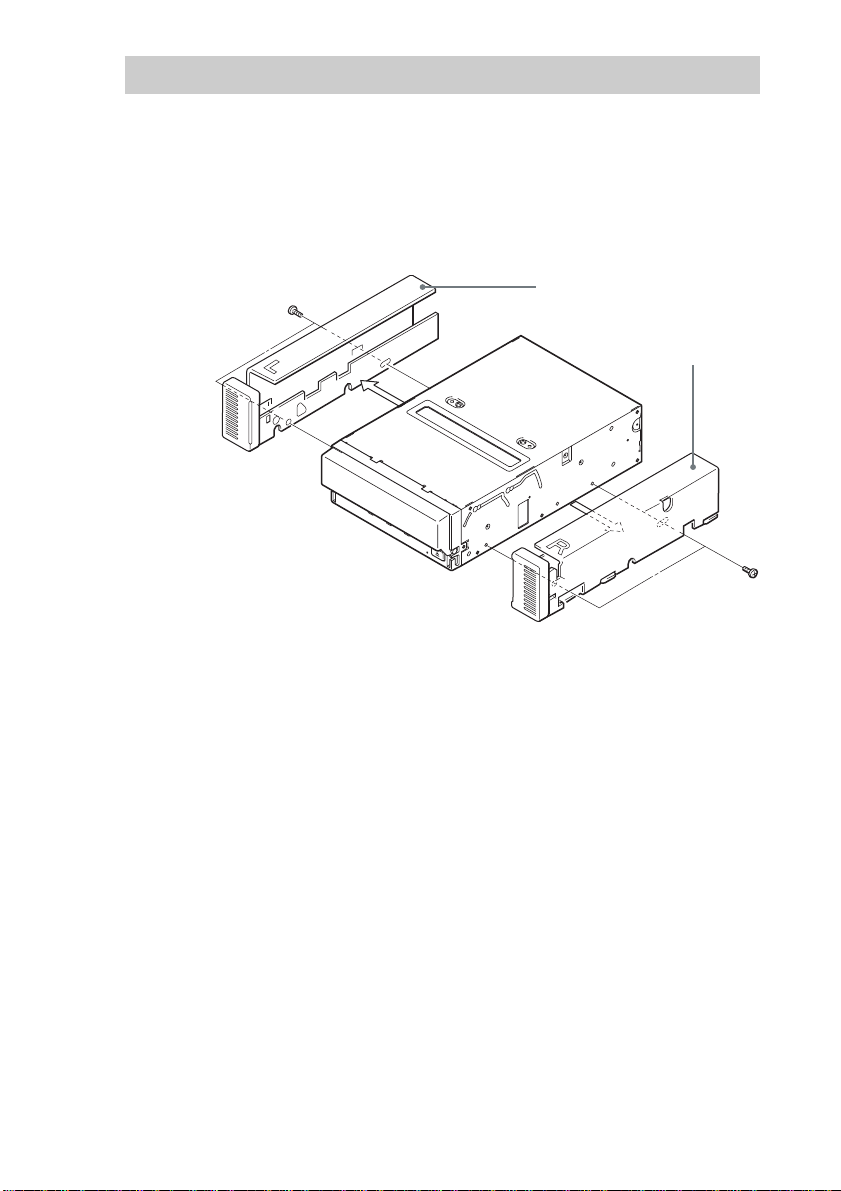
Reconfiguring from 5.25" Model to 3.5" Model
You can reconfigure the 5.25" model to the 3.5" model yourself.
1 Remove the 2 screws for each side rail.
2 Take the side rail off.
Side Rail (L)
Side Rail (R)
15
Page 16
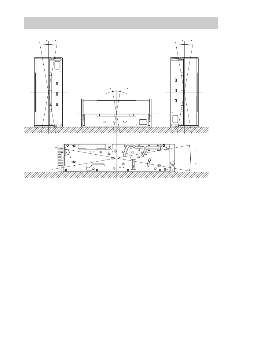
Orientation
10
10
10
10 10
10
10
10
16
Page 17
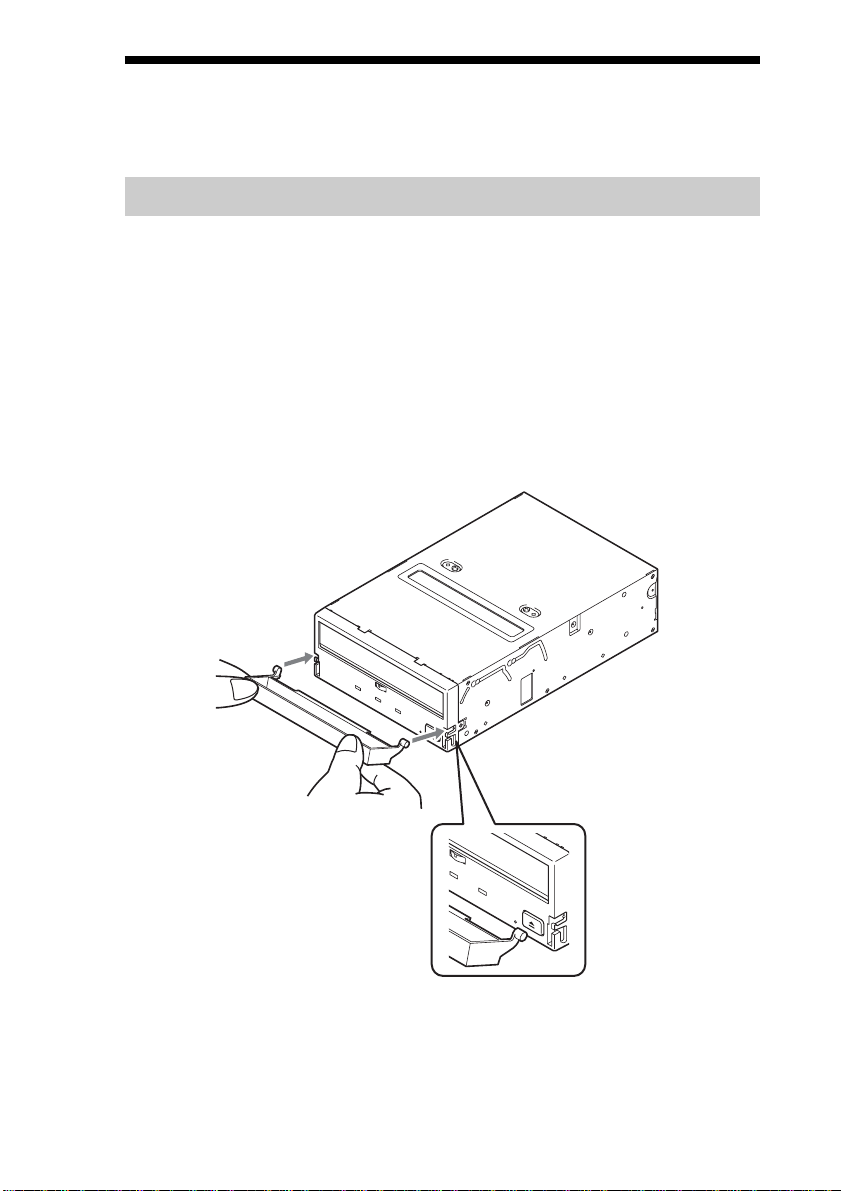
Attaching and Removing the Dust Cover
Attaching the Dust Cover
1 Align the dust cover’s hinge clips (one on each side) with the
pins of the drive bezel.
• The dust cover should be positioned so that the magnets* on the
cover’s back face the drive bezel.
*
This magnet does not affect the tape of the cartridge.
• Holding the dust cover at an angle as shown in the figure below, set
the hinge clips on top of the bezel pins, positioning them so that
they bracket the pins.
17
Page 18
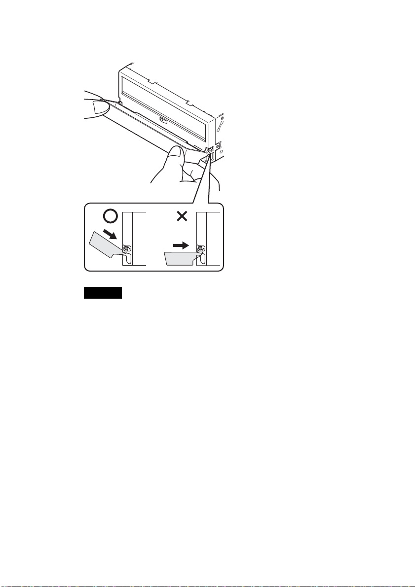
2 Press down at an angle on each side in turn until you hear
the hinge clips click into place.
Caution
Do not press the dust cover in horizontally from the front. Doing so
could cause the dust cover to break.
3 Close the dust cover.
This completes attachment of the dust cover.
18
Page 19
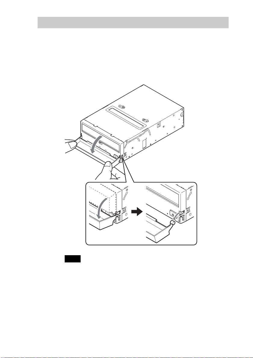
Removing the Dust Cover
1 Open the dust cover.
2 Holding the dust cover at both corners, carefully raise the
dust cover.
The dust cover hinge clips and drive bezel pins uncouple.
Note
We recommend that you use the drive with the dust cover.
19
Page 20
Operation
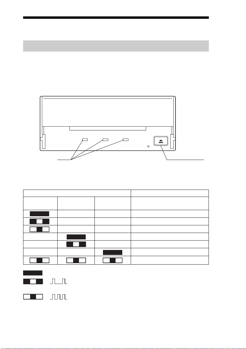
Location of 3 LEDs
There are three LED indicatiors (TAPE MOTION LED, CLEANING
REQUEST LED, REPLACE TAPE LED) and an EJECT button on the
front panel of the SDX-700V series drives.
Front Panel
Advanced
Intelligent
Tape
TAPE
MOTION
CLEANING
REQUEST
REPLACE
TAPE
LED
LED Indication for Drive Status
The LED indicators are defined as follows
LED
TAPE CLEANING REPLACE
MOTION REQUEST TAPE
Independent Independent Tape loaded
Independent Independent Tape access in progress (write/read)
Independent Independent Tape access in progress (others)
Independent Independent Cleaning is requested
Independent Independent Cleaning is not completed
Independent Independent Media error occurred
H/W error occurred
on
Slow
1 pulse (0.9 sec on/0.3 sec off)
Fast
1 pulse (0.3 sec on/0.3 sec off)
Sense
EJECT button
20
Page 21
Drive Operation
Loading a Cartridge
Note
While setting the data cartridge, do not turn off the host computer. This
may cause a malfunction or damage data.
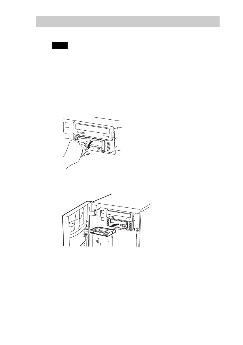
1 Turn on the host computer. Check that the drive’s TAPE
MOTION LED, CLEANING REQUEST LED and REPLACE
TAPE LED go off.
2 Open the dust cover.
3 Set the AIT data cartridge orientation as shown here and
insert it into the data cartridge slot.
By inserting the data cartridge to the extent, it is automatically set in
the drive and the TAPE MOTION LED lights.
21
Page 22
Unloading a Cartridge
The cartridge can be removed from SDX-700V series drives in response to
a SCSI Unload command, or by pressing the EJECT button.
By pressing EJECT button, the tape is rewound and the cartridge ejected
from the slot.
Write-protecting a Cartridge
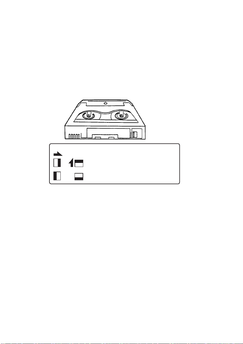
Cartridges can be write-protected by sliding the tab on the back of the
cartridge. In this state, data can be read from the tape but not written onto it.
AIT-1 AIT-2
AIT-3
Using your fingernail, push the switch in the
direction of the arrow to protect the tape from
writing or accidental erasure.
Return the switch to its original position to reenable writing.
Using a Cleaning Cartridge
A cleaning function is built into SDX-700V series drives so the use of a
cleaning cartridge is not needed. If, however, the drive experiences
excessive errors, the use of a Sony cleaning cartridge is recommended.
22
Page 23
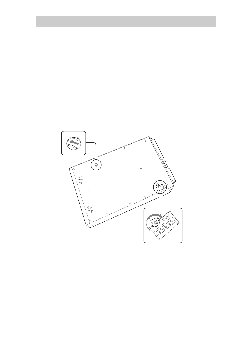
Emergency Tape Removal Procedure
1 Remove the drive from the chassis or enclosure to allow
access to the bottom of the drive.
2 Remove the drive’s top cover.
3 Locate the small opening in the bottom of the drive and
insert the tip of a precision screwdriver so that the Loading
motor shaft can be rotated.
4 Rotate the motor shaft clockwise to bring the threading
mechanism back to the initial position.
Reel motor
Loading motor
Emergency Tape Removal Procedure
23
Page 24
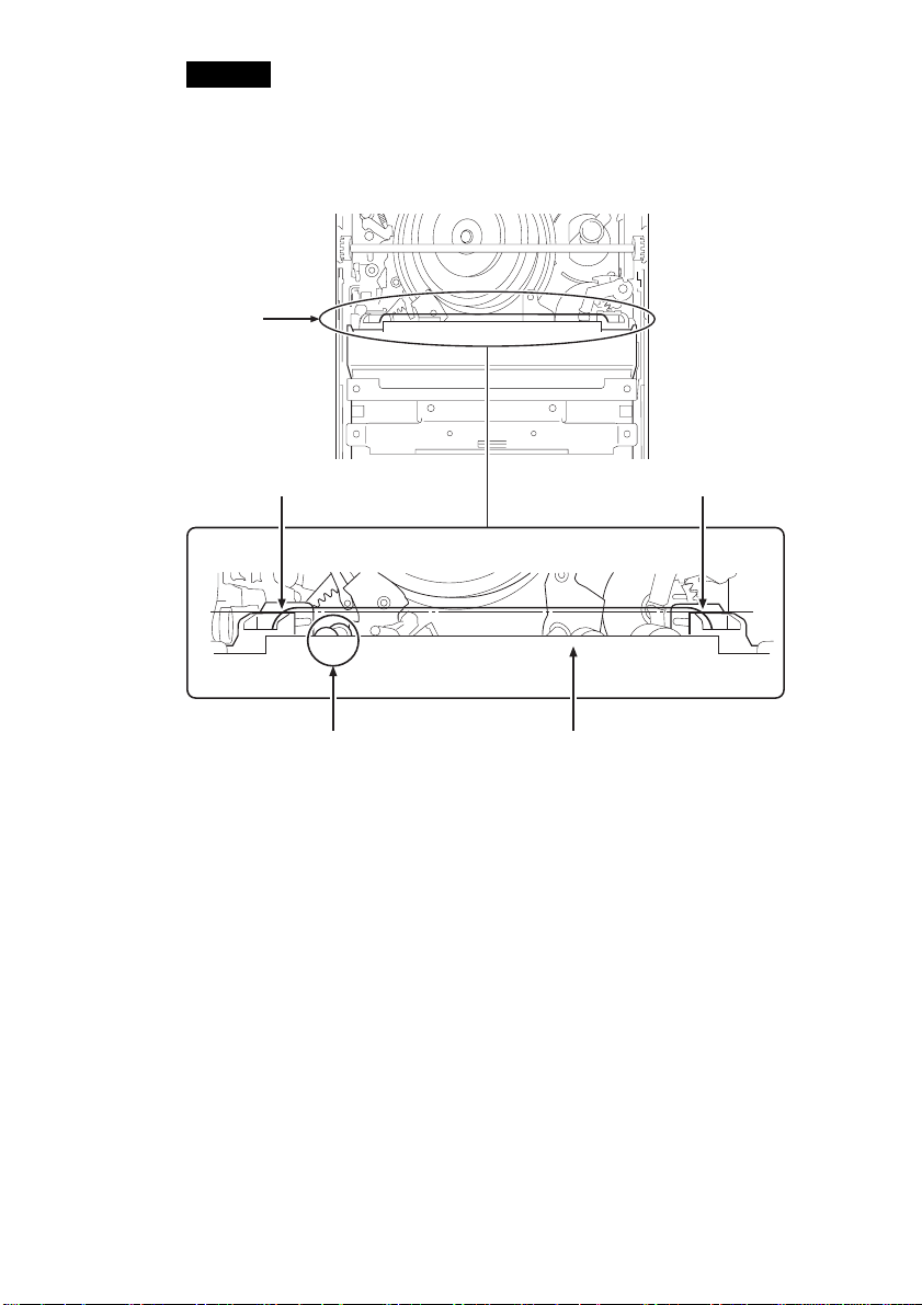
Caution
Stop rotating the motor shaft immediately, when the guide B gets to the
area below the line C-C (This line is defined by 2 circular tape guide
surfaces of the cartridge). Otherwise, the gear of the drive can be
damaged.
A
Tape guide surface Tape guide surface
CC
detail A
B
The Initial Position of the Threading Mechanism
Cartridge
5 Before the manual ejection procedure, tape slack must be
removed in order to prevent tape damage. Rotate the gear
mechanism located on the bottom of the drive
counterclockwise to tighten the tape.
6 After the tape slack has been removed, continue to turn the
Loading motor shaft located on the bottom of the drive
clockwise with a precision screwdriver until the tape
cartridge is lifted out of the drive mechanism and is ejected.
7 Return the drive to Sony for repair.
24
Page 25
WORM Function
SDX-700V series drives support the WORM function. This section
explains the WORM function.
What is “WORM”?
“WORM” is an acronym for “Write Once Read Many”, a function that
allows data to be written to the same place on a tape only once, but permits
that data to be read from the tape for any number of times. This drive
supports WORM cartridges. When a WORM cartridge is used with an
application that supports the WORM function, data that has been written to
a tape can not be accidentally deleted or overwritten.
A WORM drive operates in the same manner as a non-WORM drive when
used with a non-WORM cartridge (henceforth referred to as “regular
cartridge”).
The operation of a WORM drive and a non-WORM drive differs according
to the type of cartridge that is being used.
Tape Drive Cartridge
Non-WORM drive
WORM drive
Regular Cartridge
(without WORM logo)
Read/Write Enabled
Read/Write Enabled
WORM Cartridge
(with WORM logo)
Waiting for Eject
Read/Append-Write Enabled
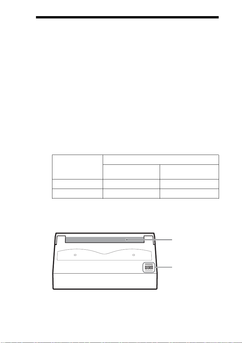
WORM Cartridges
WORM cartridges can be distinguished from regular cartridges by their
WORM logo and red shutters.
AIT-2 WORM cartridge: SDX2-50W
AIT-3 WORM cartridge: SDX3-100W
Red
WORM logo
25
Page 26

How to Write Data onto a WORM Cartridge
As with a regular cartridge, there is no limit on how many times data can be
read from a WORM cartridge. When writing data to a WORM cartridge,
the data can not be written to a portion of the tape that has already been
written.
When writing data onto a WORM cartridge, it is appended after data that
has already been written onto the cartridge. Accordingly, you must move to
the EOD area before writing data onto the cartridge.
SCSI Commands Supported by WORM Drives
WORM drives support the same SCSI commands supported by nonWORM drives. However, if an attempt is made to write to a portion of a
tape where data has already been written, the following error information is
returned: “Sense Key = 07, ASC = 27h, ASCQ = 00: Persistent Write
Protect” or “Sense Key=03, ASC=27h, ASCQ=04: Write Position Error.”
AIT WORM-compliant Software
To find out whether your backup application is AIT WORM compliant,
contact the manufacturer of the software.
Notes
• Sony cannot accept liability for data written onto a WORM cartridge that
is lost as a result of using this unit.
• Sony accepts no responsibility for any financial damages, lost profits, or
claims made by third parties arising from the use of this product.
26
Page 27

Interface Implementation
Supported SCSI Messages
Abort Message Parity Error
Bus Device Reset Message Reject
Command Complete No Operation
Disconnect Restore Pointers
Extended Message Save Data Pointer
– Synchronous Data Transfer
Request
– Wide Data Transfer Request
Identify ( w/&w/o Disconnect )
Ignore Wide Residue
Supported SCSI Commands
Erase
Inquiry
Load/Unload
Locate
Log Sense
Log Select
Mode Select
Mode Sense
Prevent Allow Medium Removal
Read
Read Block Limits
Read Buffer
Read Position
Receive Diagnostic Result
Release Unit
Report Density Support
Report Luns
Request Block Address
Request Sense
Reserve Unit
Rewind
Seek Block
Send Diagnostic
Space
Test Unit Ready
Verify
Write
Write Buffer
Write Filemarks
27
Page 28
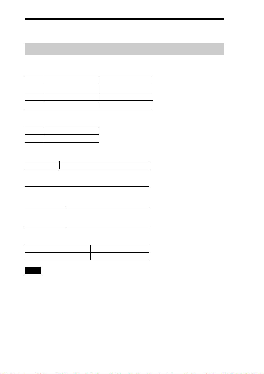
Specifications
Product Specifications
Dimensions
(not including bezel and protruding parts)
3.5" 5.25"
Height 41.2 mm (1.62 in) 41.2 mm (1.62 in)
Width 101.6 mm (4.0 in) 146.0 mm (5.75 in)
Depth 155.0 mm (6.1 in) 155.0 mm (6.1 in)
Mass
3.5" 780 g (27.5 oz.)
5.25" 1050 g (37 oz.)
Altitude
Operating 0 to 3048 m (0 to 10,000 ft.)
Vibration
Operating Swept Sine 5 to 500 Hz
Non-operating Swept Sine 5 to 500 Hz
*0.25 G Peak 1 Octave/min.
3 axes, 3 directions
*0.5 G Peak 1 Octave/min.
3 axes, 3 directions
Acoustic Noise (A) curve weight
Streaming Write/Read 35 dB (A)
Insert/Eject 60 dB (A)
Note
The sound-meter on (A) scale is located 1m (3.3 ft.) in front of the center of the
drive front panel.
28
Page 29
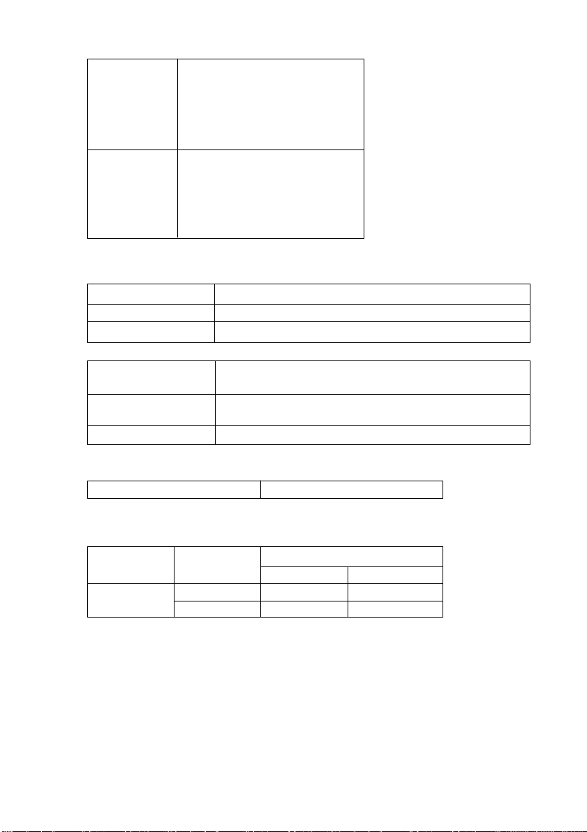
Shock
Operating No Data Loss
Half Sine
Performance
5 G Peak 3 ms
3 axes, 3 directions
*Interval of 10 seconds
Non-operating No Device Damage
Half Sine
90 G Peak 3 ms
(30 G Peak 11 ms)
3 axes, 3 directions
*Interval of 10 seconds
Temperature and Humidity Range
Temperature
Operating 5˚C to 40˚C (∆T<10˚C/h) (41˚F to 104˚F (∆T<18˚F/h))
Non-operating (mech.) – 40˚C to 70˚C (∆T<20˚C/h) (– 40˚F to 158˚F (∆T<36˚F/h))
Non-operating (tape) – 40˚C to 45˚C (∆T<20˚C/h) (– 40˚F to 113˚F (∆T<36˚F/h))
Humidity
Operating 20 to 80% RH, non-condensing
Maximum wet bulb temperature = 26˚C (78.8˚F)
Non-operating (mech.) 5 to 95% RH (∆RH<30%/h)
Maximum wet bulb temperature = 45˚C (113˚F)
Non-operating (tape) 20 to 80% RH (∆RH<30%/h)
Air-cooling Requirement
Surrounding temperature < 40˚C (104˚F)
Clean air flow is recommended to minimize the possibility of data loss.
Power Requirements
Voltage Max Ripple
5 V +/– 5 % 100 mVp-p 1.6 A 1.9 A
12 V +/– 10 % 150 mVp-p 0.5 A 1.2 A
Typical Maximum
Current
29
Page 30

Sony Contacts
For further information, please contact:
Sony Electronics Inc., Tape Storage Solutions (USA)
URL: http://www.storagebysony.com
Sony Corporation
Electronic Devices Marketing Group, Product Marketing Div.
Computer Peripherals Dept. Tape Streamer Section
Osaki Gate City East Tower, 1-11-1, Osaki
Shinagawa-ku, Tokyo, 141-0032 Japan
TEL: (81) 3-5435-3486 FAX: (81) 3-5435-3565
Sony of Canada Ltd., AV/IT Marketing Group
Computer Peripherals Product Marketing
115 Gordon Baker Road Toronto, Ontario, M2H 3R6 Canada
TEL: (416) 499-1414 or (1) 800-961-7669
FAX: (416) 499-8541
Sony Business Europe
URL: http://www.sonyisstorage.com/
Electronics Devices Marketing (Singapore)
(A division company of Sony Electronics (S) Pte. Ltd.)
Enterprise Storage Solutions Dept.
2 International Business Park, #01-10 Tower One,
The Strategy, Singapore 609930
TEL: 65-6544-8000 FAX: 65-6544-7390
Sony Corporation of Hong Kong Ltd.
Computer Peripheral Sales & Marketing Division
Electronic Devices Marketing Hong Kong
45/F, The Lee Gardens, 33 Hysan Avenue, Causeway Bay, Hong Kong
TEL: (852) 2909-1008 FAX: (852) 2909-2001
Sony Corporation of Hong Kong Ltd. Beijing Rep. Office
Computer Peripheral Div.
Full Link Plaza Tower A 11/F., No.18 Chaoyangmenwai Ave., Beijing
100020 P.R.C.
TEL: 86-10-6588-0558 FAX: 86-10-6588-0855
URL: http://www.sony.com.cn
30
Page 31

Sony Corporation of Hong Kong Ltd. Shanghai Rep. Office
44F., HSBC Tower, 101 Yin Cheng East Road, Pudong, New Area,
Shanghai, P.R.C. Postcode 200120
TEL: 86-21-6841-3222 FAX: 86-21-6841-0280
Sony Brasil Ltda.
Rua Inocéncio Tobias, 125-BlocoA, CEP01144-000, São Paulo -SP-Brasil
TEL: (55) 11-3824-6586 to 6598 FAX: (55) 11-3611-9064
URL: http://www.sonybrasil.com
Sony Australia Limited
33-39 Talavera Rd.
NORTH RYDE, NSW 2113
TEL: 1300-13-7669 FAX: 02-9870-5864
e-mail: [email protected]
Sony New Zealand
Akoranga Business Park
NORTH SHORE, AUCKLAND
TEL: 0800-76-6969 FAX: 09-308-9300
e-mail: [email protected]
Sony Chile Ltda
Av. Kennedy 8017, Las Condes, Santiago, Chile
TEL: (02) 210-6000 FAX: (02) 210-5417
Sony Taiwan Limited
Optical Devices Storage Dept. Data Storage Section
5F, 145 Changchun Road, Taipei 104, Taiwan
TEL: 886-2-2522-7920 FAX: 886-2-2522-2153
Sony Korea Corporation EDMK CP Sales & Marketing Team
34F, ASEM Tower, World Trade Center, 159-1, Samsung-Dong,
Kangnam-Ku, Seoul, 135-798, Korea
TEL: 82-2-6001-4249 FAX: 82-2-6001-4115
URL: http://www.sony.co.kr/cp/
Sony Gulf FZE Computer Display & Peripheral Div.
P.O.BOX 16871, Jebel Ali, Dubai, U.A.E.
TEL: 971-4-8815488 or 8816912 FAX: 971-4-8817210 or 8816259
Sony Marketing of Japan
Business Solution Dept. Server Solution Marketing Section
URL: http://www.sony.co.jp/STORAGE
31
Page 32

Printed in Japan
 Loading...