

Page 1

Network
Surveillance
Recorder
3-869-887-21 (1)
Installation Manual Page 2 __________________________________
設置説明書 Page 29 _______________________________________
Manuel d’installation Page 59 ________________________________
Installationsanleitung Page 88 ________________________________
Manuale all’installazione Page 118 ____________________________
Manual de instalación Page 147 ______________________________
Page 177 _________________________________________
L
GB
JP
FR
DE
IT
ES
CS
NSR Series
© 2008 Sony Corporation. All rights reserved.
Page 2
©2006 Sony Corporation
Table of Contents
Usage Precautions ................................................. 3
Overview ................................................................ 4
System Requirements ............................................ 5
Package Contents .................................................. 6
Features and Functions ......................................... 7
Front ................................................................... 7
Rear .................................................................... 9
Installation ........................................................... 11
Installation Without a Rack .............................. 11
Rack Mount Installation ................................... 12
Connecting a Monitor ...................................... 14
Connecting the Keyboard, Mouse and Remote
Control Unit (RM-NS10) ............................... 14
Connecting the Power Cord ............................. 14
Connecting the Network Cable ........................ 14
Connecting a Network Camera ........................ 15
Connecting Other Devices ............................... 15
Connecting Remote Client ............................... 15
Turn the Power On and Off ................................ 16
Turning On the Power ...................................... 16
Turning Off the Power ...................................... 16
Basic Configuration ......................................... 16
Camera IP Address Configuration and
Registration to NSR .......................................19
Reconstructing Data Volume (Changing RAID
Types) (Only the NSR-100/50) ............................21
STATUS LED ....................................................... 23
Miscellaneous ....................................................... 24
LICENSE AGREEMENT ................................ 24
Concerning GPL-LPGL ................................... 24
MPEG-4 Video Patent Portfolio License ......... 25
Troubleshooting ............................................... 25
I/O Port ................................................................. 27
Pin Assignment of I/O Port .............................. 27
Using the I/O Receptacle ................................. 27
Wiring Diagram 1 for Sensor Input .................. 27
Wiring Diagram 2 for Sensor Input .................. 27
Wiring Diagram for Alarm Output ................... 28
Trademarks
• “IPELA” and are trademarks of Sony Corporation.
• Microsoft and Windows are either registered trademarks or trademarks of
Microsoft Corporation in the United States and/or other countries.
• Ethernet is a registered trademark of Fuji Xerox Co., Ltd.
• Other products or system names appearing in this document are trademarks or registered trademarks of their respective owners.
Further, the ® or ™ symbols are not used in the text.
Before using the recorder, be sure to read this manual.
• Reproduction or duplication, in whole or part, of the software or operation
manual supplied with the recorder, as well as renting or leasing of the
software without the authorization of the right holder is prohibited under
copyright law.
• Sony assumes no responsibility for damages, loss of income, or any
claims from a third party arising out of use of the recorder or supplied software.
• For complete terms and conditions of the warranty for the recorder, refer
to the warranty card included in the package.
• The software supplied with the recorder cannot be used with any other
recorders.
• It is not possible to install any software into the equipment other than the
software supplied by Sony specifically for use with the equipment.
• Note that the specifications of the recorder and supplied software are
subject to change for improvement without prior notice.
• The recorder uses high security MD5 for password saving.
Disclaimer of liability for recorded content
Sony Corporation does not accept any liability whatsoever for any problems
arising from a failure to record, or from damage or erasure of recorded content on this equipment, for any reason. This includes claims for compensation of recorded content, and for any concomitant and consequential
damages. Sony Corporation will not repair, restore, or duplicate any recorded
content. Your use of this product is subject to these conditions.
Before reading this manual
Be sure to read the “Important Safeguards” supplement.
2
Table of Contents
Page 3

Usage Precautions
Important Information About Safety
• The electrical specifications of this unit are as follows.
Be sure to connect the unit only to a power source that
conforms fully to these requirements.
- Voltage: 100 - 127 / 200 - 240 V AC
- Current consumption: 8/4 A
- Line frequency: 50/60 Hz
• Use only the supplied power cord. Do not coil the
power cord or bundle it with other cords. Do not piggy
back connections. If current ratings are exceeded,
there is a risk of fire and other accidents.
• Make sure that all AC outlets and power cords are
properly grounded.
• Do not use the unit with the cover or case opened or
removed. Otherwise there is a risk of fire and electric
shock. Do not attempt to open or remove the cover or
case yourself. Always consult your supplier if opening
is necessary.
Important Information About Installation
Locations for use/storage
To prolong the life of the product, avoid use or storage
in the following locations.
• Locations that can become extremely hot or cold. (The
allowable usage temperature range is +5 ºC to +40 ºC/
+41 ºF to +104 ºF.)
• Locations exposed for an extended time to direct
sunlight, and locations near heating appliances. (Note
that the temperature in a closed car in summer can
exceed +50 ºC/+122 ºF.)
• Locations with high levels of humidity or dust
• Locations subject to strong vibrations
• Locations subject to strong magnetic fields
• Locations in the vicinity of radio or TV transmitters
creating a strong magnetic field
Do not block the ventilation openings
• The ventilation openings on the sides of the unit serve
to prevent internal heat buildup. Always leave a
clearance of at least 10 cm (4 inches) on both sides as
well as behind and above the unit.
• Do not use the unit in a closed box or other enclosure.
• Make sure that there are no cables or other objects in
the vicinity of the fan opening on the rear of the unit.
If the opening is blocked, internal heat buildup can
occur, leading to the risk of fire and damage.
• Also when the unit is installed in a rack, you must
make sure that the fan opening on the rear as well as
the ventilation openings on the front are not blocked
by cables or other objects. Do not install the unit in an
environment where the above requirements cannot be
met.
Use the unit in a horizontal position
• The unit is designed to be operated in a horizontal
position.
• Do not install the unit on a slanted surface, and protect
the unit from shocks.
• When the unit is dropped or otherwise subject to
strong shocks, it can be seriously damaged.
• When installing the unit in a rack, make sure that a
horizontal position is maintained. If the unit is not
properly levelled, malfunction may occur. Also, it is
highly recommended to properly anchor the rack to a
wall or similar, so that it cannot topple over.
Maintenance
• Before cleaning the unit or performing any other kind
of maintenance, be sure to disconnect the power cord
from the AC outlet.
• For cleaning, lightly wipe the cabinet and panels with
a dry cloth. To remove stubborn stains, lightly moisten
the cloth with a mild, neutral detergent and wipe with
a dry cloth afterwards.
• Do not use cleaning alcohol, solvents, benzine,
insecticide, or any other volatile substances, because
these may damage the finish and lead to discoloration.
• Dust can accumulate in the ventilation openings on the
front of the unit. When removing the dust, make sure
that you do not subject the unit to shocks or vibrations.
Transport
Use the original packing material or similar packing to
protect the unit from shocks.
Precautions for products with built-in
HDD
This unit has a built-in hard disk drive (HDD). The HDD
is a precision device. If subject to shock, vibration, static
electricity, high temperature or humidity, data loss can
occur. When installing and using the unit, closely
observe the following precautions.
Protect from shocks and vibrations
When subject to shocks or vibrations, the HDD can be
damaged and loss of data on the HDD can occur.
• When transporting the unit, use the specified packing
material. When transporting on a dolly or similar, use
a type which does not transmit excessive vibrations.
Excessive shocks and vibrations can damage the
HDD.
• Never move the unit while it is powered. Also before
removing or inserting the unit in a rack, make sure that
power is off.
• Protect all HDD-equipped devices in the rack from
shocks.
• Before removing or inserting the unit in a rack, make
sure that power to any other HDD-equipped devices in
the rack is also switched off.
• Do not remove panels or outer parts of the unit.
GB
Usage Precautions
3
Page 4

• When placing the unit on a floor or other surface,
make sure that the unit is equipped with the specified
rubber feet, and put the unit down carefully. If there
are no feet, mount the rubber feet first. Do not place
the unit near other devices that may become a source
of vibrations.
Wait for 30 seconds after turning power off
For a brief interval after the power is turned off, the
platters inside the HDD will still keep spinning and the
heads will be in an insecure position. During this
interval, the unit is more susceptible to shocks and
vibrations than during normal operation. For a period of
at least 30 seconds after turning power off, avoid
subjecting the unit even to very light shocks. After this
period, the hard disk will be fully stopped and the unit
can be manipulated.
Temperature and humidity related precautions
Use and store the unit only in locations where the
specified temperature and humidity ranges are not
exceeded.
Temperature range for operation: +5 to +40 ºC
(+41 to +104 ºF)
Humidity range for operation: 20 to 80% relative
humidity (maximum wet-bulb temperature 30 ºC/
86 ºF, no condensation)
Temperature range for storage: –20 to +60 ºC
(–4 to +140 ºF)
Humidity range for storage: 20 to 90% relative
humidity (maximum wet-bulb temperature 40 ºC/
104 ºF, no condensation)
When HDD seems to be faulty
Even if the HDD is showing signs of malfunction, be
sure to observe all the above precautions. This will
prevent further damage from occurring until the problem
can be diagnosed and corrected.
HDD replacement
The HDD, fan, and battery of the unit are consumable
parts that will need periodic replacement. When
operating at room temperature, a normal replacement
cycle will be about two to three years. However, this
represents only a general guideline and does not imply
that the life expectancy of these parts is guaranteed.
Regarding parts replacement, consult your supplier.
Overview
The NSR series is a hard disk recorder for network
cameras. The NSR allows you to monitor and record
network camera images (JPEG or MPEG-4). It also
allows you to play back the recorded images and search
through it, making the NSR a truly versatile monitoring
system.
Control compatible cameras from remote
locations
You can pan, tilt, and perform zoom operations of
compatible cameras.
Compatible with analog cameras
You can monitor and record images from analog
cameras when you purchase and install an optional
camera server (SNT-V704).
Large-capacity hard disks allow recording for
long periods of time
The
NSR
is equipped with large-capacity hard disks. The
NSR-100 can record up to approximately 920 GB
the NSR-50 can record up to approximately 460 GB
data, and the NSR-25 can record up to approximately 230
1)
GB
of data. For example, if you record images from 16
cameras at 1 fps
2)
VGA, JPEG; one frame equals about 31
KB) with the NSR-100, you can record approximately a
month’s worth of images (15 hours a day)
1) Includes the database capacity managed by the internal
software.
2) fps: frames per second.
3) When set to RAID 0.
Slim type (2U), space-saving 19-inch rack
mounting model
With the optional rack mounting kit (sold separately),
the unit can be installed in a standard universal pitch EIA
19-inch rack.
High-resolution up to 480 fps (VGA, JPEG)
recording
The NSR-100 can support up to 64 cameras, the NSR-50
can support up to 32 cameras, and the NSR-25 can
support up to 20 cameras. The NSR-100 records images
at a total frame rate of 480 fps* (240 fps with the
NSR-50, 120 fps with the NSR-25), VGA (640 × 480
pixels) resolution, JPEG (1 frame approx. 31 KB) image
format, for a crisp image quality.
1)
of data,
1)
of
3)
4
* Maximum frame rate when 16 cameras are connected to the
recorder. Each camera has a frame rate of approximately 30
fps. This frame rate may become less because of
fragmentation on the internal hard disks. Values are based
on Sony measurements. These values are not guaranteed, as
performance may change due to the user’s operating
environment.
Overview
Page 5

High reliability
The NSR-100/50 performs high reliability through:
• NSR-100: RAID 0, 1+0, and 5
• NSR-50: spanning*
and RAID 1
When used with a RAID 1, 1+0 or 5, the system can
continue functioning even if one of the hard disks develops
a malfunction. Similarly, because the system software and
settings are stored on the internal flash memory of the
NSR, if the system software develops a malfunction,
lightning-quick restoration of the system is possible. The
NSR also supports uninterruptible power supplies
(UPS)**, making them extremely reliable systems.
* Spanning: Function allowing several hard disks to be
virtually seen as one.
** Sony recommendation only.
Notes
• When you use RAID 0 with the NSR-100 or spanning
with the NSR-50, there is no data redundancy. Also,
storage capacity varies according with the RAID level.
• RAID is not available for the NSR-25.
Other features
• You can display the images from up to 64 cameras
(8 × 8 images) on one screen.
• The NSR is capable of manual, scheduled, and alarm
recording, among others.
• The NSR is equipped with a motion detection
function
1)
(Video Motion Detection (Recorder)).
• Run searches for recorded images by camera name,
date, alarm, and other methods.
• Create privacy zones by using the dynamic masking
functions
2)
. Dynamic masking covers pan, tilt, and
zoom.
• Precise alarm processing is made possible by
performing the various types of filtering
3)
that use the
image processing results sent from the camera in the
form of object information metadata. Because filtering
can be applied to metadata that has already been
recorded, you can also search for areas of interest after
recording is finished.
• Audio recording and playback
4)
are also supported
from compatible cameras.
System Requirements
The hardware required in order to use this recorder are
as follows.
• Sony Network cameras
Contact your dealer for details about compatible Sony
network cameras.
• Monitor
• USB Keyboard
•USB Mouse
• Network switch
• 1000Base-T/100Base-TX/10Base-T cable
• CF (CompactFlash) card or USB memory device
1) For details about monitors supported by the NSR, contact
your retailer.
The following “Generic” type monitors can be selected.
Frequency is indicated at the end of each line.
- Generic LCD Display; LCD Panel 1024×768; 40-70
- Generic LCD Display; LCD Panel 1280×1024; 50-75
- Generic LCD Display; LCD Panel 1600×1200; 60
- Generic CRT Display; Monitor 1024×768; 50-70
- Generic CRT Display; Monitor 1280×1024; 50-90
- Generic CRT Display; Monitor 1600×1200; 50-90
The following resolutions can be specified.
- XGA (1024×768)
- SXGA (1280×1024)
- UXGA (1600×1200)
2) Use a USB keyboard with a cable. However, keys other
than the standard may not function. Wireless or infrared
USB keyboards may also not function properly.
3) Use a USB mouse with a cable. However, three-button or
wheel mice may not function properly. Wireless or infrared
USB mice may also not function properly.
4) Required when backing up system information such as
logs.
- For CF, use a card that has been formatted in advance
- For USB memory, use a device that supports general
- CF cards are not compatible with the NSR-25.
1)
2)
3)
with VFAT.
USB Mass Storage Class specifications.
4)
1) Some functions are limited depending on the number of
cameras connected.
2) Some functions are limited depending on which camera
models are connected.
3) To perform motion detection and object detection using
metadata, a camera that supports motion detection by
metadata is required. The use of metadata is supported for
up to 32 cameras.
4) The optional active speakers are required.
Important
This manual only describes how to install and configure
the NSR. For detailed explanations about how to use the
recorder, refer to the “User’s Guide” (PDF) on the
supplied “NSR Series Manual, Tool & Source Codes CD”.
System Requirements
5
Page 6

Package Contents
Check that the following items are included in this
package:
• NSR-100, NSR-50, or NSR-25 Surveillance Recorder
(1)
• Front panel key (2)
• Installation Guide (this document) (1)
• Remote Control Unit Operation Card (1)
• NSR Series Recovery CD
• NSR Series Manual, Tool & Source Codes CD
• Important Safeguards (1)
• Safety Notice (1)
• Warranty booklet (1)
• Rubber feet (4)
Notes
• This package may contain additional hardware and/or
documentation for those options.
• Save the boxes and packing materials for future use.
• The rack mounting kit is optional (sold separately). To
order a rack mounting kit, contact your retailer.
• The following are included on the NSR Series
Manual, Tool & Source Codes CD.
Manual folder: User’s Guide and Remote Control
Unit Operation Card data (multilingual)
SourceCode folder: Source code for GPL/LGPL-
compliant software
Tool: Remote client software (RealShot Manager),
CAM file playback application (Media File
Player), and accompanying user’s guides
(1)
(1)
6
Package Contents
Page 7
Features and Functions
708q
9q
q
q
q
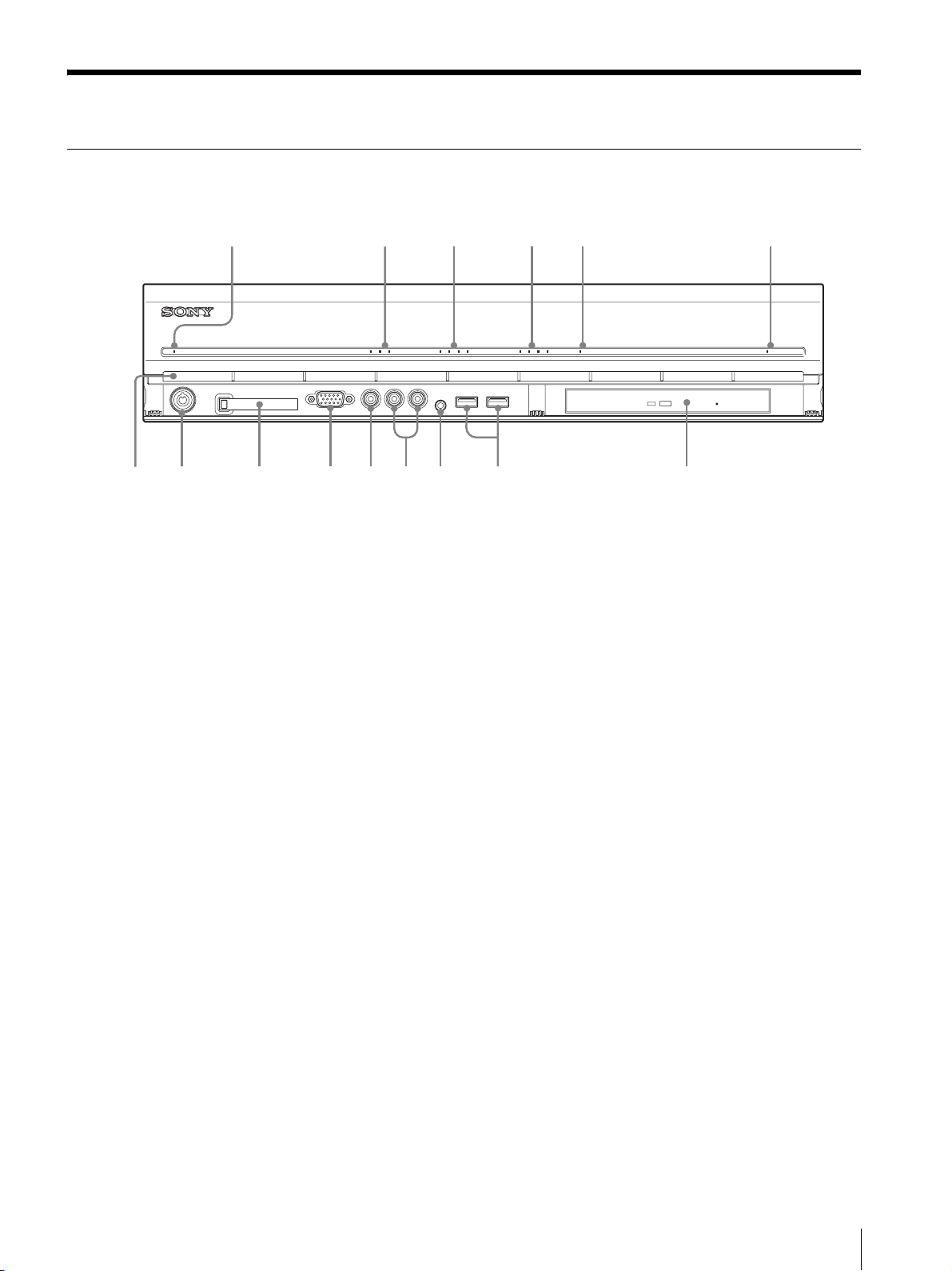
Front
NSR-100/50
123 4 5 6
POWER 1 2 3NETWORK 1 2 3 4HDD 1 2 3 4 ERRORSTATUS REC
a
f
g
d
s
A Power LED
Alternates between green and amber lights when the unit
is starting up.
Lights green when startup is complete.
Lights amber when it is on standby.
B Network LED (1 to 3)
Lights green when there is activity at the corresponding
LAN connector at the rear of the NSR.
C HDD LED
Blinks green when the internal hard disks are accessed.
Lights amber when an error occurs with a hard disk.
D Status LED (1 to 4)
Lights in sequence (1, 2, 3, 4) when the NSR starts.
When an error occurs, the corresponding status LED
lights together with the error LED, which lights or blinks
to indicate the type of error.
For details, see “STATUS LED” (page 23).
E Error LED
Lights or blinks when an error occurs.
F REC LED
Lights when recording images.
H USB connector
Use this connector to connect a USB keyboard, mouse,
USB flash memory or the RM-NS10 remote control to
the NSR.
I Audio input connector*
Use this connector to input audio from a peripheral
audio device, such as a microphone.
J Audio output connectors (L and R)
Use these connectors to output audio to a peripheral
audio device.
K Video output connector
Use this connector to output video to a peripheral video
device, such as a VCR.
The displayed images are the same as those for monitor
connector 1.
L Monitor connector 1
Use this connector to connect a monitor.
M CompactFlash card slot
Use this slot to save configuration data from the NSR
hard disks to a CompactFlash card.
G DVD/CD drive
Use this drive to write data from the NSR hard disks to
DVD and CD.
* For details on compatible media, refer to the “User’s
Guide” (PDF) on the supplied “NSR Series Manual, Tool
& Source Codes CD”.
Features and Functions
7
Page 8
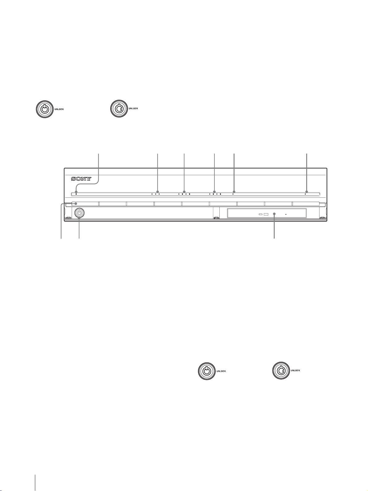
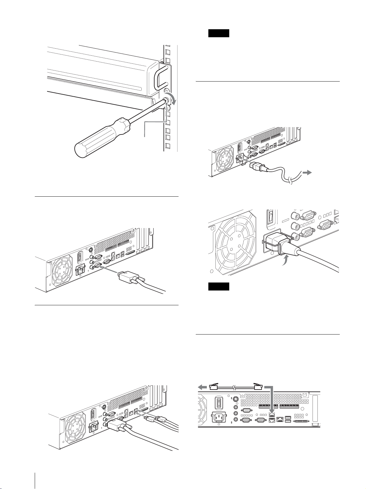
N Lock
789
Use this in conjunction with the supplied front panel key
to lock the front bezel. When the front bezel is locked,
you cannot pull out the front bezel. Also, do not lock the
front bezel when the front bezel is pulled out. You can
distinguish the locked position from the unlocked
position by looking at the lock, as illustrated below.
O Vent ho les
These openings allow air to flow from the front of the
NSR to the rear.
Do not block the vent holes, allow dust to accumulate in
the inner mesh of the vent holes, or obstruct the airflow
in any way. Obstructing the airflow allows heat to build
up inside the NSR and may result in fire or damage.
The front bezel is
locked
The front bezel is
unlocked
NSR-25
123 4 5 6
POWER 1 2 3NETWORK 1 2 3 4HDD 1 2 3 4 ERRORSTATUS REC
A Power LED
Alternates between green and amber lights when the unit
is starting up.
Lights green when startup is complete.
Lights amber when it is on standby.
B Network LED
Lights green when there is activity at the corresponding
LAN connector at the rear of the NSR.
C HDD LED
Blinks green when the internal hard disks are accessed.
Lights amber when an error occurs with a hard disk.
D Status LED (1 to 4)
Lights in sequence (1, 2, 3, 4) when the NSR starts.
When an error occurs, the corresponding status LED
lights together with the error LED, which lights or blinks
to indicate the type of error.
For details, see “STATUS LED” (page 23).
E Error LED
Lights or blinks when an error occurs.
F REC LED
Lights when recording images.
* This feature is not currently supported.
G Combo drive
Use this drive to write data from the NSR hard disks to
CD.
H Lock
Use this in conjunction with the supplied front panel key
to lock the front bezel. When the front bezel is locked,
you cannot pull out the front bezel. Also, do not lock the
front bezel when the front bezel is pulled out. You can
distinguish the locked position from the unlocked
position by looking at the lock, as illustrated below.
The front bezel is
locked
The front bezel is
unlocked
I Vent ho les
These openings allow air to flow from the front of the
NSR to the rear.
Do not block the vent holes, allow dust to accumulate in
the inner mesh of the vent holes, or obstruct the airflow
in any way. Obstructing the airflow allows heat to build
up inside the NSR and may result in fire or damage.
8
Features and Functions
Page 9
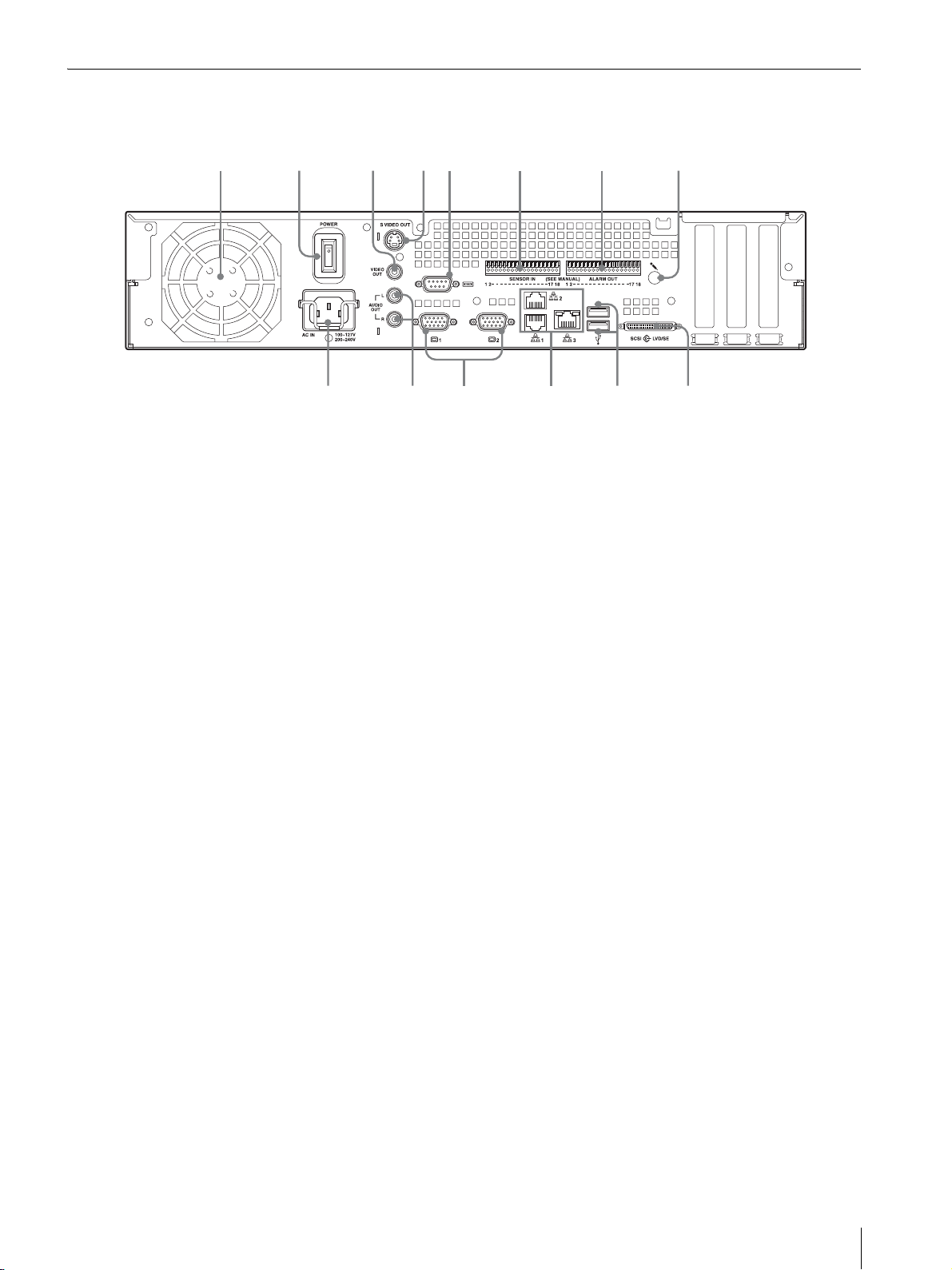
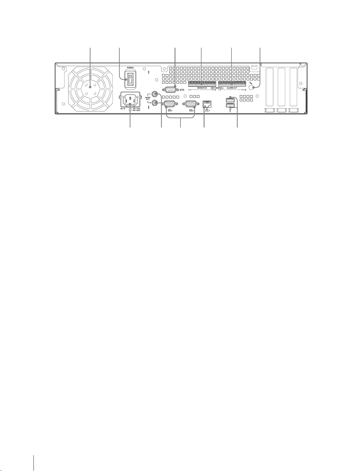
Rear
9q
0q
q
q
NSR-100/50
231 654 7 8
f
A Fan
Take care not to obstruct the fan grille. If the grille is
obstructed, heat may build up in the unit, leading to
damage and/or fire.
B Power switch
Press the switch in the a position to turn on the unit.
C Video output connector
Use this connector to output video to a peripheral video
device, such as a VCR.
The displayed images are the same as those for monitor
connector 1.
D S-video output connector
Use this connector to output video to a peripheral video
device equipped with an S-video connector.
The displayed images are the same as those for monitor
connector 1.
E Serial connector (RS-232C)
Use this connector to connect the control line of the
uninterruptible power supply (UPS).
F Sensor input connector
Use this connector to connect the sensor input lines.
For connection details and wiring diagrams for sensor
inputs, see “I/O Port” (page 27).
d
s
H Audio input connector*
Use this connector to input audio from a peripheral
audio device, such as a microphone.
I SCSI connector*
Use this connector to connect a peripheral SCSI device.
J USB connector
Use this connector to connect a USB keyboard, mouse,
USB flash memory or the RM-NS10 remote control to
the NSR.
K LAN connectors (1 to 3)
Use these connectors to connect 10 Base-T, 100 BaseTX, or 1000 Base-T network cables to the NSR.
LAN1: Network cameras
LAN2: Remote Clients
LAN3: External storage devices**
L Monitor connectors (1 and 2)
Use these connectors to connect a monitor.
M Audio output connectors (L and R)
Use these connectors to output audio to a peripheral
audio device.
N Power supply connector
Use this connector to connect the power cord.
a
G Alarm output connector
Use this connector to connect the alarm output lines.
For connection details and a wiring diagram for alarm
output, see “I/O Port” (page 27).
* This feature is not currently supported.
** The external storage device is not supported depending on
the software version. Consult your dealer.
Features and Functions
9
Page 10
NSR-25
7890q
21 43 5 6
a
A Fan
Take care not to obstruct the fan grille. If the grille is
obstructed, heat may build up in the unit, leading to
damage and/or fire.
B Power switch
Press the switch in the a position to turn on the unit.
C Serial connector (RS-232C)
Use this connector to connect the control line of the
uninterruptible power supply (UPS).
D Sensor input connector
Use this connector to connect the sensor input lines.
For connection details and wiring diagrams for sensor
inputs, see “I/O Port” (page 27).
E Alarm output connector
Use this connector to connect the alarm output lines.
For connection details and a wiring diagram for alarm
output, see “I/O Port” (page 27).
F Audio input connector*
Use this connector to input audio from a peripheral
audio device, such as a microphone.
G USB connector
Use this connector to connect a USB keyboard, mouse,
USB flash memory or the RM-NS10 remote control to
the NSR.
H LAN connectors
Use these connectors to connect 10 Base-T, 100 BaseTX, or 1000 Base-T network cables to the NSR.
I Monitor connectors (1 and 2)
Use these connectors to connect a monitor.
J Audio output connectors (L and R)
Use these connectors to output audio to a peripheral
audio device.
K Power supply connector
Use this connector to connect the power cord.
* This feature is not currently supported.
10
Features and Functions
Page 11
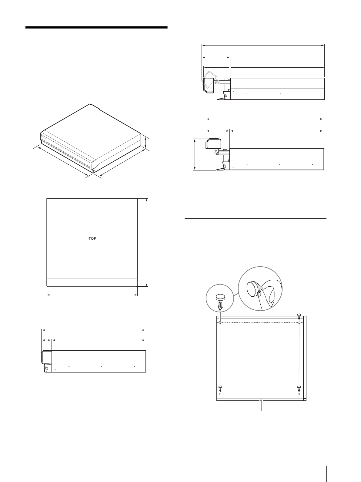
When the front bezel is opened
Installation
When you are sure that the site chosen to set up the
NSR provides appropriate space and strength to
support the recorder, connect the AC power cord.
The NSR-100 weighs approx. 14 kg (31.1 lb.), the
NSR-50 weighs approx. 12 kg (26.7 lb.), and NSR-25
weighs approx. 11 kg (24.2 lb.). The NSR has the
following dimensions.
3.4 in.
(87 mm)
Top
16.9 in.
(430 mm)
16.4 in.
(417 mm)
19.4 in. (494 mm)
4.6 in.
(117 mm)
4.2 in.
(106 mm)
4.0 in.
(102 mm)
4.8 in.
(123 mm)
14.8 in. (377 mm)
18.9 in. (479 mm)
14.8 in. (377 mm)
You can set up the NSR in a rack mount or on a flat
surface. If you plan to set it up on a flat surface, you must
attach the supplied rubber feet to the bottom of the
chassis.
16.9 in. (430 mm)
When the front bezel is closed
16.4 in. (417 mm)
14.8 in. (377 mm)1.6 in. (40 mm)
Installation Without a Rack
Attach the provided rubber feet to the recorder.
Place the recorder upright so that the bottom surface is
visible. Then affix the adhesive surfaces of the rubber
16.4 in. (417 mm)
feet on the bottom of the recorder as illustrated below.
Remove
the film
Rubber
foot
Bottom of the unit
Installation
11
Page 12
Rack Mount Installation
Install the NSR in a rack using the optional rack
mounting kit (sold separately).
Warning
• Do not use a rack mounting kit other than the optional
mounting kit (sold separately) for the NSR, as doing
so is dangerous and may result in fire, shock, or injury.
• If you mount the NSR in a rack, make sure not to place
heavy object on it.
• Before mounting the NSR in a rack, we recommend
that you mark its intended position in the rack with a
felt-tip pen. Mounting the NSR in the rack otherwise
than horizontally could result in malfunctions.
• To order a rack mounting kit, contact your retailer.
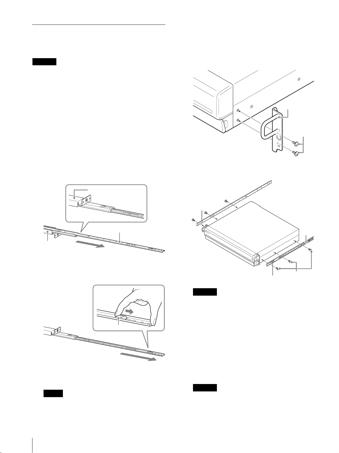
Pulling Out the Inner Rails
Pull out the inner rails from the rail assemblies.
1
Pull out the inner rail from one of the rail
assemblies as far as it can go.
Back of rail assembly
Preparing the NSR
Use the supplied fasteners and screws to install the inner
rail on the NSR.
1
Use the supplied flat head screws to attach the
mounting ears to the front of the side panel.
Mounting ear
Flat head
screws
2
Use the remaining supplied round head screws to
install the rails to the NSR, as illustrated.
Inner rail
Rail assembly
2
Turn the rail assembly over. As you pull the green
tab outward to release the lock, pull the inner rail all
the way out.
Green tab
3
Repeat the same procedure with the other rail
assembly to pull out its inner rail.
Note
The inner rail will be installed on the NSR, while
the rail assembly will be installed on the rack.
Green tab
Caution
Using screws other than the supplied screws may
damage the unit. Be sure to use the supplied screws
to install the rails.
Round head
screws
Preparing the Rack
Install the rails on the rack.
1
Determine where you want to install the rails on the
rack.
We recommend marking this position with a
marker or felt tip pen.
Caution
Rails installed at different heights could result in
NSR malfunctions.
Rail
12
Installation
Page 13
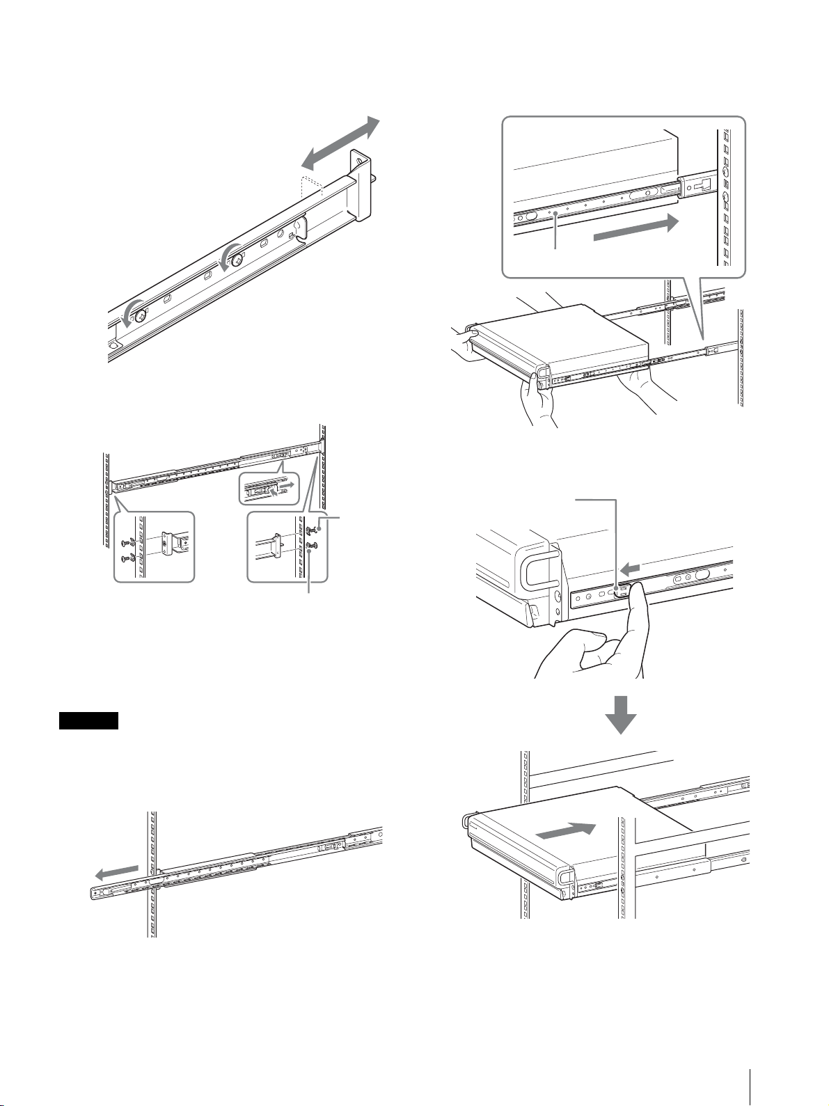
2
Install the rails on the rack.
(1) Adjust the length of the rails to match the length
of your rack.
(2) Use the supplied truss screws and washers to
secure both ends of the rails to the rack.
2
Lift the NSR, fit the inner rails into the slide rail
grooves (white), and then slide the assembly until it
stops.
Inner rail
3
As you pull the green tab inward to release the lock,
slide the NSR as far as it can go.
Truss
screws
Washers
Mounting the NSR on the Rack
Insert the NSR into the rack, and then secure it.
Caution
At least two people are needed in order to handle the unit
to prevent personal injury.
1
Pull the sliding rails from the rail assemblies.
Green tab
Installation
13
Page 14
4
Use the supplied round head screws to secure the
NSR to the rack.
Round head
screw
Note
When using the NSR-25, only the two USB
connectors on the rear of the unit are available.
Connecting a keyboard and mouse makes setting up
for the first time easier.
Connecting the Power Cord
1
Connect the power cord to the power supply
connector at the rear of the NSR, and then connect
the other end to the power outlet.
* The remainder of this manual uses illustrations and screens
of the NSR-100/50.
Connecting a Monitor
Connect the monitor to the monitor1 connector on the
rear of the recorder.
Connecting the Keyboard, Mouse
and Remote Control Unit
(RM-NS10)
1
Connect the keyboard to the USB connector on the
rear (or front) of the recorder.
2
Connect the mouse or the remote control unit
(RM-NS10) to the USB connector.
1
2
Lift the power cord safety clip and snap it around
the power cord to prevent it from disconnecting.
Note
Before installing, carefully read “Important
Information About Safety” (page 3). When using
more than one NSR, also make sure to have
sufficient power capacity.
To the power
outlet
Connecting the Network Cable
Connect the network cable.
Connect the one end of the network cable to one of the
LAN connectors at the rear of the NSR. Connect the
other end to the network switch.
14
Installation
Page 15
Note
The default IP address for LAN port 1 is follows;
• LAN connector 1: 192.168.0.1
• LAN connector 2: 192.168.1.1
(only the NSR-100/50)
• LAN connector 3: 192.168.2.1
(only the NSR-100/50)
If you want to change the default IP address, refer to the
“User’s Guide” (PDF) on the supplied “NSR Series
Manual, Tool & Source Codes CD”.
Connecting an Uninterruptible Power
Supply
1
Connect the uninterruptible power source to the
power outlet.
2
Connect the NSR to the UPS with the supplied
power cord.
3
Connect the NSR to the UPS with the dedicated serial
cable to the serial connector on the rear of the NSR.
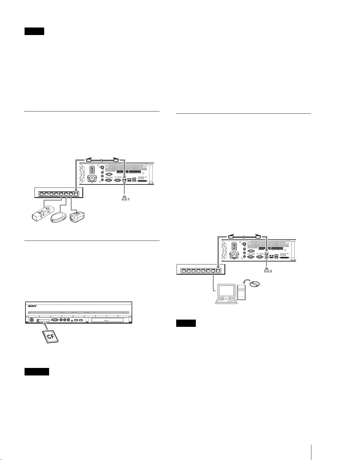
Connecting a Network Camera
Use a network cable to connect LAN connector 1 to a
network switch, and then connect the desired network
camera to the network switch with another network
cable.
Network switch
Network Camera
Connecting Other Devices
Using a CompactFlash Card (Only the
NSR-100/50)
Insert your CompactFlash card in the direction
illustrated. Make sure that you insert your card with the
label side facing up and in the direction of the arrow.
Connecting Remote Client
If a remote client is required, the supplied RealShot
Manager Controller software can be used.
RealShot Manager Controller runs on Windows
computers. For details on system requirements, refer to
the release notes accompanying the RealShot Manager
Controller install archive. Also, make sure to use the
RealShot Manager supplied with the NSR.
1
Use a network cable to connect LAN connector to
a network switch.
When using the NSR-100/50, connect to LAN
connector 2 on the unit.
2
Connect the network cable to a computer when
RealShot Manager Controller software is installed.
Network switch
(For the NSR-100/50)
RealShot Manager
Controller software
POWER 1 23LAN 1 2 34HDD 1 2 3 4 ERRORSTATUS REC
When ejecting a CompactFlash card, press the eject
button on the left of the card slot.
Caution
Be careful when ejecting a CompactFlash card, because
it may be expelled from the drive energetically.
Windows PC
Notes
• For details on installation and other topics related to
the RealShot Manager Controller software, refer to the
supplied NSR Series Manual, Tool & Source Codes
CD.
• When using RealShot Manager as a remote controller
for the NSR, select [Controller] during installation of
RealShot Manager.
• The default connection port for the RealShot Manager
server function on the NSR unit is “8081”. The
connection port can be changed from the NSR.
• When using the NSR-100/50, use LAN connector 2 at
the rear of the NSR even if connecting it to the user
area of a network.
Installation
15
Page 16
Turn the Power On and
Initial Operations
Off
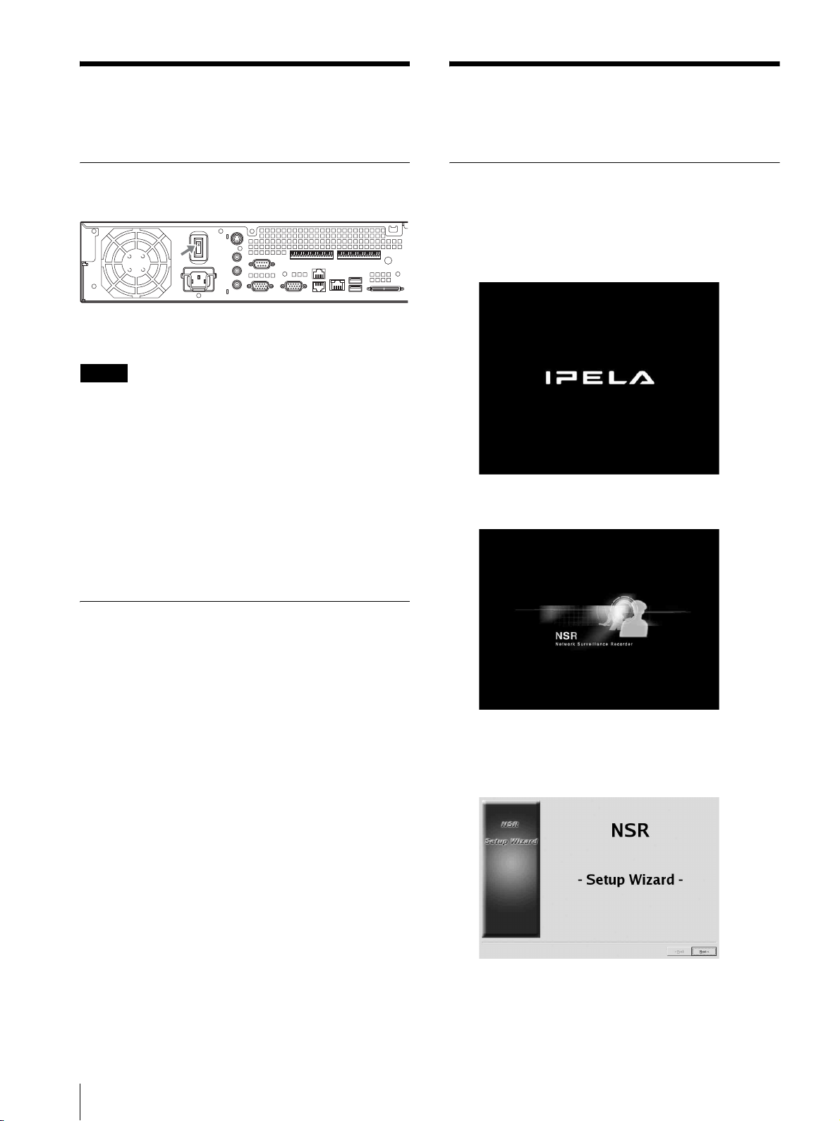
Turning On the Power
Press the power switch.
When startup is complete, the power indicator LED
lights green.
Notes
• Immediately (about 2 seconds) after the power is
turned on, the cooling fan makes a loud noise. This is
normal and not a sign that the unit needs to be
serviced.
• When the NSR starts for the first time, the Setup
Wizard starts automatically. For details about the
setting procedure, refer to the “User’s Guide” (PDF)
on the supplied “NSR Series Manual, Tool & Source
Codes CD”.
• If the NSR was previously shut down improperly,
startup may take longer than usual.
(Basic Initial Setup)
Basic Configuration
1
Connect the USB keyboard and USB mouse to the
unit, and turn on the power.
The following screen appears, and a progress bar
for hardware startup appears.
Then the following screen appears, and a progress
bar for software startup appears.
Turning Off the Power
1
Log on to the NSR, and click [System] at the top of
the window.
The System Menu screen appears.
2
Click [Shutdown].
A confirmation message appears.
3
Click [OK] to confirm.
The system shuts down, and then the unit shuts
down.
The unit starts and the system settings screen
(Setup Wizard) appears.
2
Click [Next].
The [Select Language] screen appears.
16
Turn the Power On and Off / Initial Operations (Basic Initial Setup)
Page 17
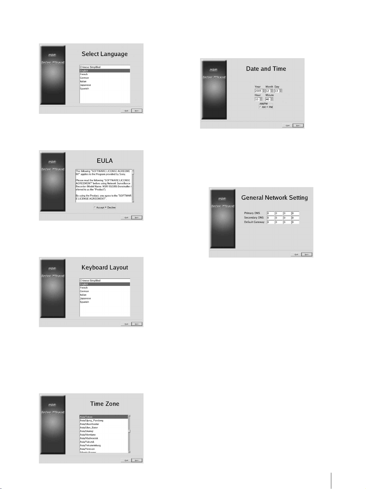
3
Select the desired display language from the list,
and then click [Next].
The [EULA] screen appears.
The [Date and Time] screen appears.
7
Verify the date and time, and configure the correct
date and time if necessary, then click [Next].
4
Read the user license agreement, click [Accept],
and then click [Next].
The [Keyboard Layout] screen appears.
5
Select the type of USB keyboard connected to the
unit from the list, and then click [Next].
The [Time Zone] screen appears.
The [General Network Setting] screen appears.
8
Perform the following steps to configure the
network settings.
(1) Enter an IP address for each server in the
[General Network Setting] screen, and click
[Next].
Primary DNS
Enter the primary DNS (Domain Name Server)
IP address.
When there is no primary DNS or one is not
necessary, do not enter an IP address.
Secondary DNS
Enter the secondary DNS IP address.
When there is no secondary DNS or one is not
necessary, do not enter an IP address.
6
Select the desired time zone from the list, and then
click [Next].
* There is no option for enabling or disabling
summer time. If you select a time zone in which
time is adjusted for summer time, the time is
adjusted for summer time automatically.
Default Gateway
Enter the default gateway IP address.
When only the local network is used or
connection to other networks is not necessary,
do not enter an IP address.
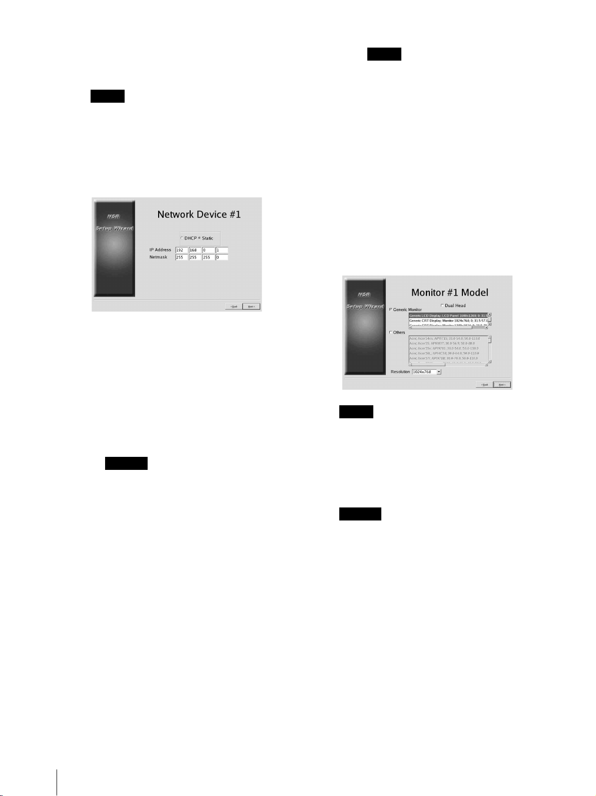
The [Network Device #1] screen appears.
(2) Configure the [Network Device] settings for
each of the LAN ports.
When using the NSR-100/50, configure the
settings for each of the three LAN ports (LAN1,
LAN2, and LAN 3).
When using the NSR-25, configure the settings
for the single LAN port (LAN1).
Initial Operations (Basic Initial Setup)
17
Page 18
Configure the settings according to the
operation environment, and click [Next] for
each of the settings screen.
Note
When using the NSR-100/50, connect the
following devices to each of the LAN ports.
LAN1: Network cameras
LAN2: Remote clients
LAN3: External storage devices (This may not
be supported depending on the software version.
For details, consult your dealer.)
When using a DHCP server to configure
address settings automatically
Select [DHCP].
Note
The default settings for network devices are
as follows.
IP Address: 192.168.[0/1/2]*.1
Netmask: 255.255.255.0
* The settings for each of the network
devices #1, #2, and #3 (only network
device #1 for the NSR-25).
The [Monitor Model] screen appears.
9
Perform screen size settings depending on each
monitor port, and then click [Next].
When two monitors are connected, clicking [Dual
Head] displays the second monitor configuration
screen.
Select the appropriate monitor type and resolution
(pixels) for your monitor.
When configuring addresses manually
(1) Select [Static].
(2) Enter the following information.
IP Address
Enter the desired IP address.
Caution
• Before you enter the desired IP address,
make sure that it is not already otherwise
used on the network. Entering an IP
address already in use may lead to erratic
operation of the unit, but no error
messages appear to indicate the fact.
• Because of IP address attribution rules,
setting an invalid address such as the ones
below is not allowed.
Example: 224.0.0.0 to 255.255.255.255
0.0.0.0
127.0.0.1, etc.
Netmask
Enter the subnet mask address.
Notes
• The default setting for monitors is as follows.
Generic LCD Display; LCD Panel 1600x1200;
31.5-90; 60
Resolution 1024x768
• Most monitors will operate with [Generic
Monitor], but you can select [Others] as required.
Caution
When configuring settings for the second monitor,
the second monitor must be connected when the
NSR restarts. Be sure to connect the second
monitor before finishing the configurations.
When using the NSR-100/50, the [Video Setting]
screen appears. Proceed to step 10.
When using the NSR-25, the [Host Name] screen
appears. Proceed to step 11.
18
Initial Operations (Basic Initial Setup)
Page 19
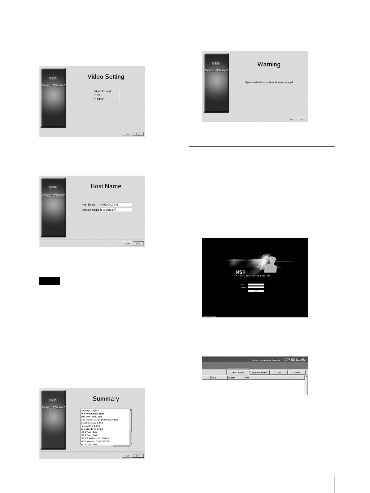
10
Select the appropriate video format, depending on
your region, [NTSC] or [PAL], and then click
[Next].
* This screen only appears when using the
NSR-100/50.
The [Host Name] screen appears.
11
Perform settings for each item, and then click
[Next].
The [Warning] screen appears.
13
Click [Finish].
The NSR restarts automatically.
Camera IP Address Configuration
and Registration to NSR
After restarting, the logon screen appears.
Next, configure the IP addresses for cameras and
register them to the NSR.
1
Type your user name and password, and then click
[Log on].
Host Name
Enter the host name.
Note
Use only alphanumeric characters, underscores (_),
and hyphens (-).
Domain Name
Enter the network domain name according to your
network.
Example: xxx.sony.co.jp
When you do not register the NSR to the DNS, you
do not need to change the default settings.
The [Summary] screen appears.
12
Confirm the settings and then click [Next].
Default User Name: admin
Default Password: admin
The Camera screen appears in the Configuration
window.
2
Click [Camera IP Setup].
If the IP addresses for the cameras have already
been set, click [Register All] and proceed to Step 5.
The Camera IP Setup window appears.
Initial Operations (Basic Initial Setup)
19
Page 20
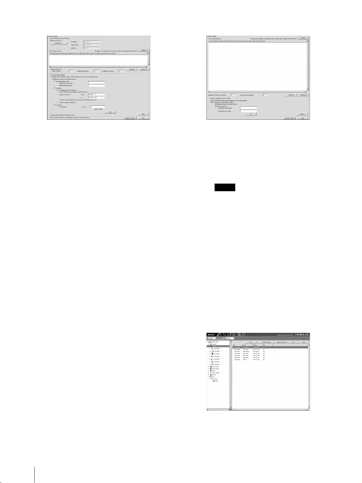
3
Perform the following settings.
5
Perform the following settings.
In the Camera IP Setup window, you can search for
cameras on the same network by MAC address and
configure their IP addresses all at once.
(1) Select the network to search in the field labeled
“1. Select Network Device for IP Setup.”
Normally, Network 1 is selected as the camera
network, and a list of the cameras found appears
in the “Found Camera List.” The check boxes of
all found cameras are selected.
(2) Enter the following information in the field
labeled “2. Set Camera network setting.”
• The user name and password of the camera
you are configuring settings for.
• The range of IP addresses on the same
network (default: 0 to 254) for which to
perform automatic assignment.
• The http port number (default: 80) for
communicating with cameras.
* If there is a fixed range of IP addresses that
can be assigned to cameras, make sure to
specify the correct range.
(3) Click [Set].
The information you entered is reflected in the
“Found Camera List.”
IP addresses are assigned within the specified
range. Because the list does not expand to
compensate if there are not enough IP
addresses, make sure the list is set correctly by
directly changing addresses in the list as needed.
At this stage, the settings have not yet been
applied to the camera.
In the Register Cameras window, a list of cameras
that have not been registered to the NSR appears
with the check box for each selected.
(1) Verify the number of cameras selected for
registration in the column labeled “Cameras to
be registered”, and confirm the user name and
password for each camera.
Note
The user name and password for the cameras are
not set by default. You can set the user name and
password for the selected cameras all at once
under “Register selected Cameras for NSR”.
(2) Click [Register].
The selected cameras are registered to the NSR.
* By clicking [Camera IP Setup], you can also
return to the previous Camera IP Setup
window.
6
When registration is complete, click [Close].
The Configuration window returns to the Camera
screen. The registered cameras are listed.
7
If necessary, configure the individual settings for
each camera.
For details about settings, refer to the supplied
user’s guide.
(4) Click [Apply].
This configures the camera settings using the
information developed in the list.
It takes a few moments for the settings to
complete.
4
When the settings for each camera are complete,
click [Register All].
The Register Cameras window appears.
20
Initial Operations (Basic Initial Setup)
Page 21
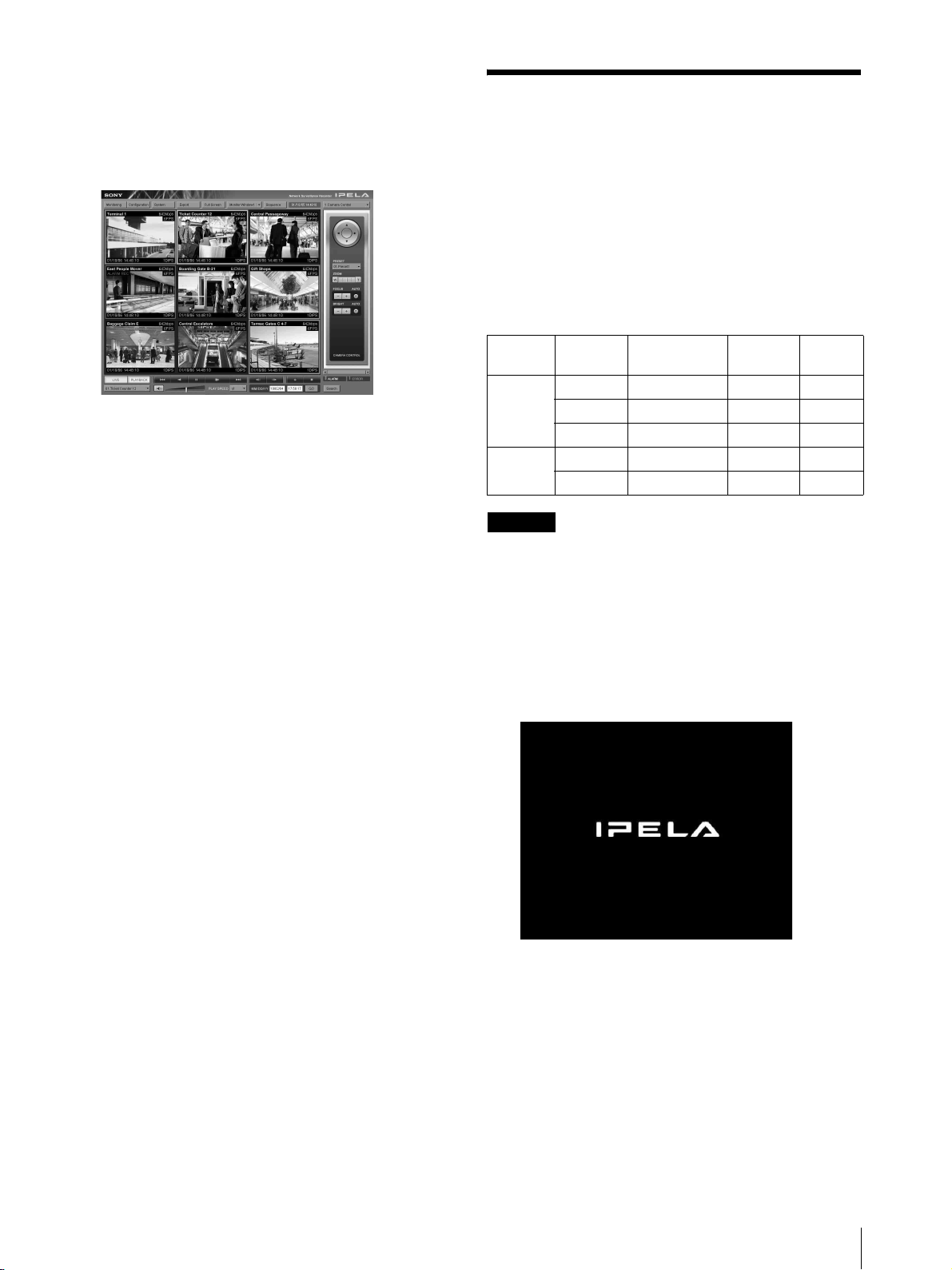
8
When you have verified the settings for each
camera, click [Monitoring].
The “Monitoring” window appears.
By clicking [Configure], you can switch to the
“Configuration” screen and make changes to the
settings.
Reconstructing Data
Volume (Changing RAID
Types) (Only the
NSR-100/50)
RAID constructions that can be set as data volumes
differ depending on the model number within the
NSR-100/50.
* RAID is not available for the NSR-25.
* For details on how to use the “Monitoring” screen
and “Configuration” screen, refer to the User’s
Guide (PDF) included on the supplied NSR
Series Manual, Tool & Source Codes CD.
Model Type
NSR-100 RAID-5 670 GB Yes Yes
RAID-1+0 450 GB Yes
RAID-0 900 GB None
NSR-50 Spanning 430 GB Partial Yes
RAID-1 210 GB Yes
Caution
• Be aware that all setting information and recorded
images are deleted when reconstructing data volume.
• When changing the settings is necessary, make sure to
change the RAID construction beforehand.
1
Connect the USB keyboard and USB mouse to the
NSR, and turn on the power.
The following screen and a progress bar for
hardware startup appear.
Approximate
capacity
Redund-
ancy
Default
setting
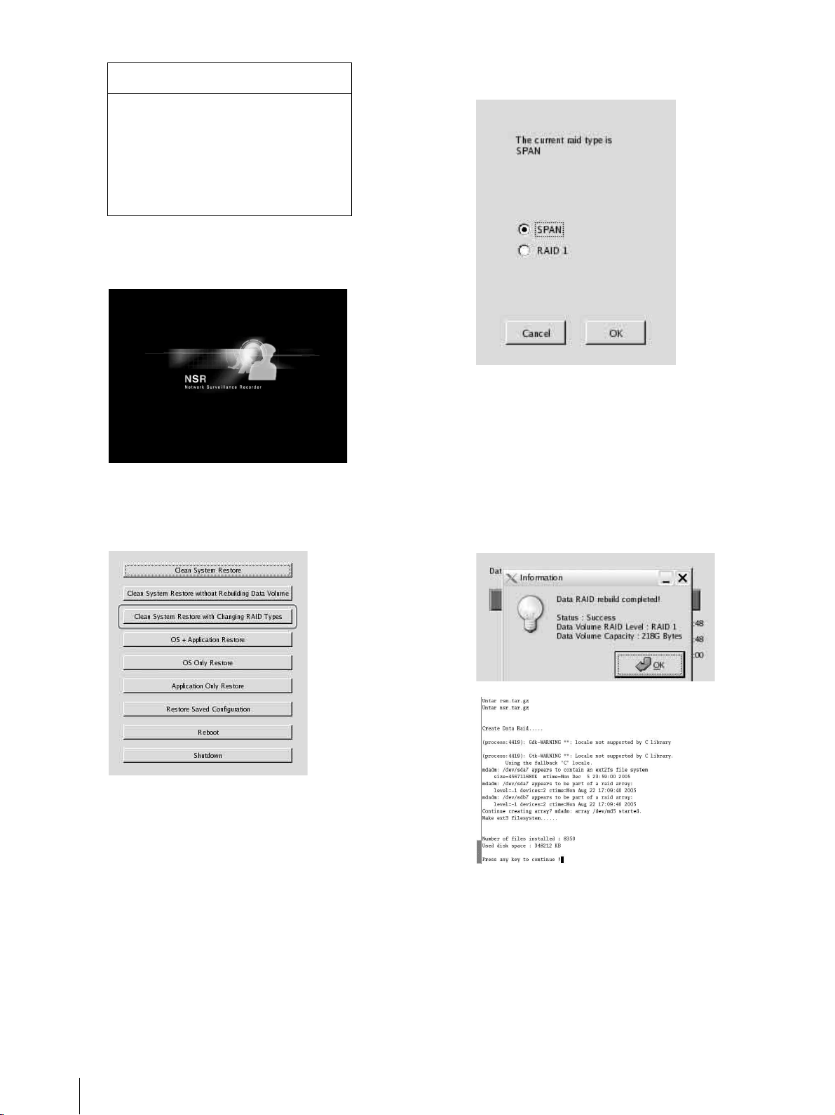
2
Press F12 on the keyboard while the progress bar is
displayed.
The screen similar to the following appears.
Example: For the NSR-50 (there are 3 menu items
for the NSR-100)
* The number of devices and their names may
differ from the following example screen.
Reconstructing Data Volume (Changing RAID Types) (Only the NSR-100/50)
21
Page 22
Boot Menu
1.QSI DVD+/-RW SDW-0826
2. WDC WD2500JD-22HBC0-(S1)
3. WDC WD2500JD-22HBC0-(S2)
4. PQI IDE DiskOnModule-(SM)
<Enter Setup>
3
Use the arrow keys on the keyboard to select [IDE
DiskOnModule], and press Enter.
Startup from DiskOnModule (DOM) begins.
After startup, the DOM menu appears.
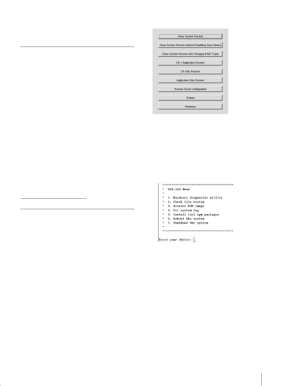
4
Click the third item from the top, [Clean System
Restore with Changing RAID Types].
5
Select the RAID Type, and click [OK].
Example: For the NSR-50
The confirmation screen appears.
6
Click [OK].
RAID reconstruction for data volume and full
system restoration begins.
This process can take up to about 5 hours. A
progress bar appears during the process.
When the process successfully completes, a
notification screen appears.
Example: For an NSR-50 with RAID 1 selected
The RAID Type selection screen appears.
22
Reconstructing Data Volume (Changing RAID Types) (Only the NSR-100/50)
7
Press Enter after the process completes and the
message [Press any key to continue!] appears.
The screen returns to the DOM menu.
8
Click [Reboot].
The NSR reboots, and the Setup Wizard appears.
Page 23
STATUS LED
When an error occurs, the STATUS and ERROR LED light or flash.
1 2 3 4 ERRORSTATUS
The STATUS LED indicates the following error situations.
Error codes displayed during boot stage
(The ERROR LED blinks when an error occurs
during boot.)
Error
STATUS
code
LED
1 Blinking
1234
2 Blinking CPU fan failure
1234
3 Blinking Defective memory module
1234
4 Blinking CMOS battery failure
1234
5 Blinking
1234
6 Blinking Hard disk controller failure
1234
7 Blinking No bootable device found
1234
ERROR
LED
Possible Cause
Vo l ta ge p ow er sup pl y
failure
Video random access
memory (RAM) or
controller failure
Error codes displayed during operation stage
(The ERROR LED lights when an error occurs
during operation.)
Error
STATUS
code
LED
1 On Critical temperature
1234
2OnCPU fan failure
1234
3 On Power supply fan failure
1234
4On
1234
5 On Hard disk drive fan 1 failure
1234
6 On Hard disk drive fan 2 failure
1234
7 On Hard disk drive is damaged.
1234
ERROR
LED
Possible Cause
Voltage power supply
failure
8 Blinking
1234
9 Blinking
1234
A Blinking RAID OS volume failure
1234
B Blinking
1234
C Blinking
1234
D Blinking Reserved for future use
1234
E Blinking Reserved for future use
1234
F Blinking RAID data volume failure
1234
No bootable Operating
System found
One or more hard disk
failure
Failure to start the X11
server
Failure to start the
application
8 On Reserved for future use
1234
9 On Reserved for future use
1234
A On Reserved for future use
1234
B On Reserved for future use
1234
COn
1234
D On Reserved for future use
1234
E On RAID data volume failure
1234
FOn
1234
* A degradation in system performance will occur when a
read error occurs while the resync operation is in progress.
Application functioning
failure
Resync operation in RAID
data volume*
STATUS LED
23
Page 24

Miscellaneous
4. The User may not export or transport the Program or
documents accompanying the Program from the country
where the User purchased the Product to any other
country.
LICENSE AGREEMENT
The following “SOFTWARE LICENSE
AGREEMENT” applies to the Program provided by
Sony.
Please read the following “SOFTWARE LICENSE
AGREEMENT” before using Network Surveillance
Recorder (Model Name: NSR-100/50/25) (hereinafter
referred to as the “Product”).
By using the Product, you agree to the “SOFTWARE
LICENSE AGREEMENT”.
Please be aware that the software used in the Product
includes a part of software under the different terms and
conditions from the following SOFTWARE LICENSE
AGREEMENT. You can confirm such software at
bundled CD media (hereinafter referred to as
“Exceptional Software”). The following “SOFTWARE
LICENSE AGREEMENT” does not apply to such
Exceptional Software and the respective terms and
conditions apply to each Exceptional Software
separately from this “SOFTWARE LICENSE
AGREEMENT”. Exceptional Software shall never be
construed as Program defined in the following
SOFTWARE LICENSE AGREEMENT.
SOFTWARE LICENSE AGREEMENT
This is a legal agreement between you (hereinafter
referred to as the “User”) and Sony Corporation
(hereinafter referred to as “Sony”) pertaining to the right
to use the software program (hereinafter referred to as
the “Program”). Using the Program indicates User’s
acceptance of these terms and conclusion of this
Agreement between the User and Sony.
1. Copyright and all other rights relating to the Program
and documents accompanying the Program are owned
by Sony or the original rightful person or organization
(hereinafter referred to as the “Original Rightful
Person”) granting Sony the right to use the Program. The
User is granted no rights other than those specified in
this Agreement.
2. Sony grants the User the non-exclusive, indivisible
and non-transferable right to use the Program for the
purpose of using the Product for which the Program
designates (hereinafter referred to as the “Right of
Use”).
3. The User may not transfer the Right of Use to any
third party nor allow for any third party to use the
Program unless the User obtains the advance written
permission of Sony.
5. The User may not (i) update, add to, or modify nor (ii)
de-assemble or de-compile the Program either in whole
or in part without Sony’s prior consent.
6. THE PROGRAM IS PROVIDED “AS IS”
WITHOUT EXPRESS OR IMPLIED WARRANTIES,
INCLUDING WARRANTIES OF
MERCHANTABILITY AND FITNESS FOR A
PARTICULAR PURPOSE OR NONDEFECTIVENESS.
7. If any dispute relating to infringement of copyright,
patent, or other intangible property rights arises between
the User and a third party as a consequence of use of the
Program, the User shall settle the dispute at the User’s
own expense, and shall make no claim against Sony or
the Original Rightful Person.
8. Sony may terminate User’s license upon notice for
failure to comply with any of these terms of this
Agreement. Any such termination shall not affect any
payments and any compensation for damage. Upon
termination, User must immediately destroy the
Program together with all copies in any form.
9. If the User is a governmental entity, the use,
duplication or disclosure of the Program and
accompanying documentation by the User are subject to
the restrictions set forth in subparagraphs (c)(1) and
(c)(2) of the Commercial Computer Software clause at
FAR 52.227-19, and subparagraph (c)(I)(ii) of the
Rights in Technical Data and Computer Software clause
at DOD FAR 252.227-7013 and any comparable federal,
state or local law or regulation and, for this purpose, the
manufacturer is Sony Corporation located at 1-7-1
Konan, Minato-ku, Tokyo, Japan.
Concerning GPL-LPGL
This product includes GPL/LGPL-compliant software.
You may acquire the source code for this software, as
well as modify and distribute it.
The source code is included on the supplied “NSR
Series Manual, Tool & Source Codes CD”.
Do not direct questions to Sony regarding the contents of
the source code.
Some software provided with this product uses the glibc
and gtk2 developmental LGPL libraries with a method
called dynamic linking (also, refer to the “User’s Guide”
(PDF) on the supplied “NSR Series Manual, Tool &
Source Codes CD”). As regulated by LGPL, the source
code for these pieces of software is not provided.
24
Miscellaneous
Page 25
However, when limited to the software owner, analysis
of the object code for the purpose of personal revisions
or debugging is permitted.
MPEG-4 Video Patent Portfolio
License
THIS PRODUCT IS LICENSED UNDER THE MPEG4 VISUAL PATENT PORTFOLIO LICENSE FOR
THE PERSONAL AND NON-COMMERCIAL USE
OF A CONSUMER FOR
(i) ENCODING VIDEO IN COMPLIANCE WITH
THE MPEG-4 VISUAL STANDARD (“MPEG-4
VIDEO”)
AND/OR
(ii) DECODING MPEG-4 VIDEO THAT WAS
ENCODED BY A CONSUMER ENGAGED IN A
PERSONAL AND NON-COMMERCIAL
ACTIVITY AND/OR WAS OBTAINED FROM A
VIDEO PROVIDER LICENSED BY MPEG LA
TO PROVIDE MPEG-4 VIDEO.
NO LICENSE IS GRANTED OR SHALL BE
IMPLIED FOR ANY OTHER USE. ADDITIONAL
INFORMATION INCLUDING THAT RELATING TO
PROMOTIONAL, INTERNAL AND COMMERCIAL
USES AND LICENSING MAY BE OBTAINED
FROM MPEG LA, LLC. SEE
HTTP://WWW.MPEGLA.COM
Example: For the NSR-100/50
When it does, proceed as follows.
1 Click [Shutdown] and turn off the NSR.
2 Referring to “Cannot access the hard drive.”, verify
whether the NSR hard disks are correctly
connected.
3 Restart the NSR and verify whether it starts.
4 If the same screen as above appears again, insert the
supplied NSR Series Recovery CD into the CD and
DVD drive, and then turn off the NSR. In this state,
restart the NSR, and select “2. Check file System”
when the following screen appears.
Troubleshooting
Before contacting your retailer or a Sony Support
Center, please check the following items. If the problem
persists, contact them.
The NSR does not work.
• Verify that the power switch is turned on.
• Verify that the power cable is connected correctly.
• Make sure the wall outlet has power. Test it by
plugging another device.
• Verify that the hard disk drives are not being accessed
(the HDD LEDs on the front of the recorder do not
blink), and then turn it off forcibly by pressing and
holding the power switch at the rear of the unit for
approximately 10 seconds. Restart the NSR.
• During the startup procedure, the NSR checks the file
system. The length of this check varies depending on
the amount of data on the NSR (in some extreme case,
it can take as long as two hours). During the file
system check, the HDD LEDs on the front of the
recorder blink.
• If the NSR does not start correctly, the following
screen may appear.
Checking the file system may take several hours.
5 When the check is finished, select “7. Shutdown the
system”, and turn off the recorder.
In addition, do not use any menu option other than
“2. Check file system” or “7. Shutdown the
system”, as the others are for maintenance
purposes.
6 Restart the NSR and immediately eject the NSR
Series Recovery CD. Then verify whether the NSR
starts correctly.
Miscellaneous
25
Page 26

The monitor remains blank.
• Verify whether the NSR is on.
• Verify whether the power cord is correctly connected.
• Verify whether the monitor cable is correctly
connected. Confirm that the monitor is connected to
monitor connector 1.
• If you configure the wrong monitor resolution, the
“Out of range” message may appear when the monitor
resolution is too low compared to the monitor output.
Press CTRL+ALT+MINUS SIGN as many times as
necessary to lower the resolution of the output video.
When the output image resolution reaches the
resolution of the monitor, the image appears.
Subsequently, reconfigure your monitor resolution.
For details, refer to the “User’s Guide” (PDF) on the
supplied “NSR Series Manual, Tool & Source Codes
CD”.
The new external hardware is not working
properly.
• Make sure the cables for the new external device are
firmly connected and the pins are not bent.
An external device connected to a USB
connector does not work.
• Reduce the number of external devices connected to
USB ports.
• Refer to the documentation that came with the device.
System cannot read the DVD/CD
information.
• Make sure that you are using the correct type of disc.
• Make sure the DVD/CD is properly inserted in the
drive.
• Check if the DVD/CD is clean and not scratched.
Cannot access the hard disk drive.
• Make sure the hard drive is properly inserted.
• Check the HDD LEDs on the front panel of the
system. Identify the defective hard disk drive by
reading the drive LEDs. A defective HDD LED does
not light up.
• Due to rapid flashing during frequent access to the
hard disk drive, the HDD LED may appear unlit in
bright environments.
Cannot access the CompactFlash card.
(Only the NSR-100/50)
• Make sure the CompactFlash card is properly inserted.
• Make sure the CompactFlash card is formatted as
VFAT file system.
• Make sure the CompactFlash card is not removed
within 10 seconds after accessing the card. If you
remove the card while files are being accessed or
transferred, the NSR may become unstable. You must
restart the system in order to access the CompactFlash
card.
Cannot access NSR from a remote client.
• Make sure the NSR is operating properly (there should
be no abnormalities with the hard disk drive, network,
software or other items).
• Make sure the correct user name, password, and
connection port are set in RealShot Manager.
• Refer to the troubleshooting section of the user’s guide
for the RealShot Manager.
The NSR heats up quickly
• Make sure that nothing is blocking the ventilation
openings on the front, sides, and rear of the unit and
dust has not accumulated in them.
The DVD/CD tray cannot be ejected.
• Make sure that the NSR is turned on.
• Slowly insert the tip of a pen or paperclip into the eject
hole on the DVD/CD drive. Pull the tray out from the
drive then remove the disc.
The NETWORK LED does not light up.
• Check the cabling and network equipment for the
proper connection.
26
Miscellaneous
Page 27
I/O Port
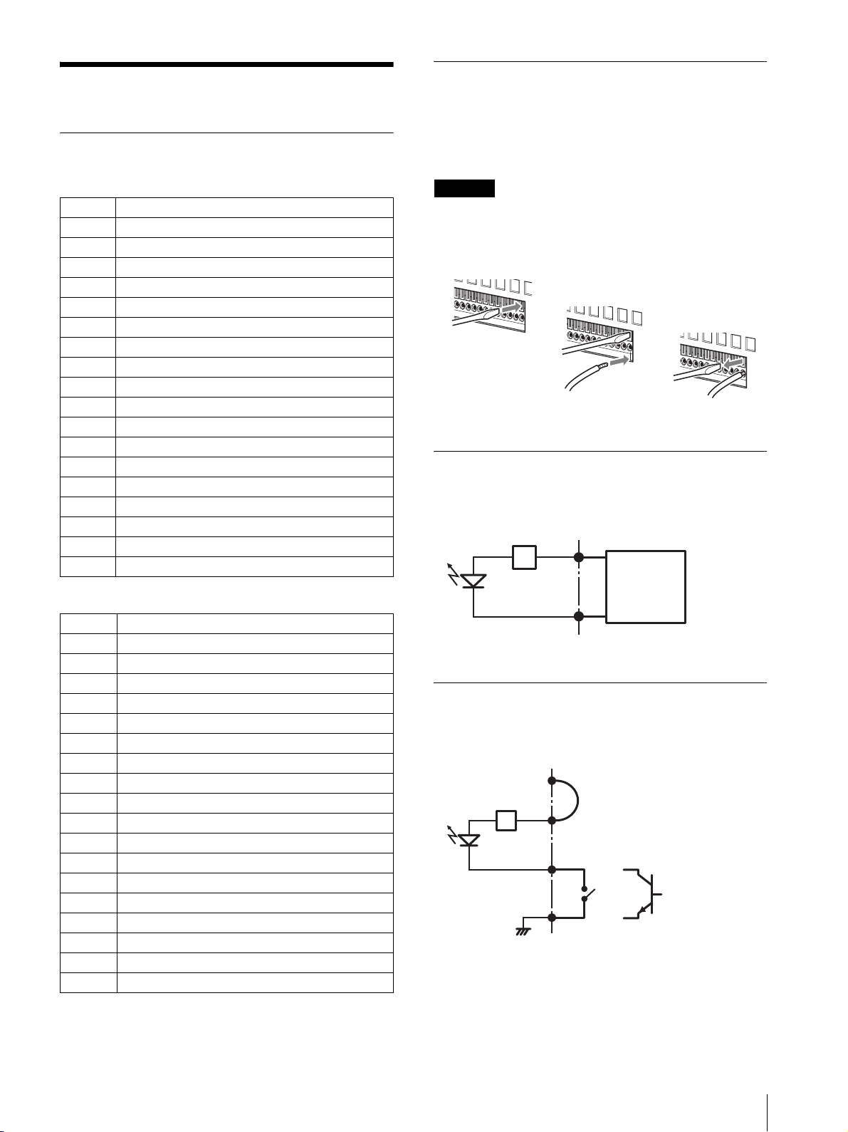
1
Pin Assignment of I/O Port
Using the I/O Receptacle
Insert a small slotted screwdriver into the upper or lower
slot of the hole you want to connect a wire to (AWG No.
28 to 18). Hold down the screwdriver and insert the wire,
then release the screwdriver.
Sensor In
Pin NO. SENSOR IN
13.3 v
2IN_8 –
3IN_8 +
4IN_7 –
5IN_7 +
6IN_6 –
7IN_6 +
8IN_5 –
9IN_5 +
10 IN_4 –
11 IN_4 +
12 IN_3 –
13 IN_3 +
14 IN_2 –
15 IN_2 +
16 IN_1 –
17 IN_1 +
18 GND
Alarm Out
Pin NO. ALARM OUT
1 GND
2 OUT_8 –
3 OUT_8 +
4 OUT_7 –
5 OUT_7 +
6 OUT_6 –
7 OUT_6 +
8 OUT_5 –
9 OUT_5 +
10 OUT_4 –
11 OUT_4 +
12 OUT_3 –
13 OUT_3 +
14 OUT_2 –
15 OUT_2 +
16 OUT_1 –
17 OUT_1 +
18 3.3 v
Caution
Do not use excessive force when inserting the
screwdriver into the slot. Doing so may result in
damage.
2
3
Repeat this procedure to connect all required wires.
Wiring Diagram 1 for Sensor Input
Inside of this unit Outside
3, 5, 7, 9, 11, 13, 15, 17pin
(SENSOR IN+)
Sensor
2.35 kΩ
2, 4, 6, 8, 10, 12, 14, 16pin
(SENSOR IN-)
device
Output:
3.3 to 24 V
DC
Wiring Diagram 2 for Sensor Input
Inside of this unit Outside
1 pin (VDD) (200 mA max)
3, 5, 7, 9, 11, 13, 15,
17pin
(SENSOR IN+)
2.35 kΩ
2, 4, 6, 8, 10, 12, 14,
16pin
(SENSOR IN-)
18pin (GND)
GND
Wire
Mechanical
switch
or
Open collector
output device
I/O Port
27
Page 28
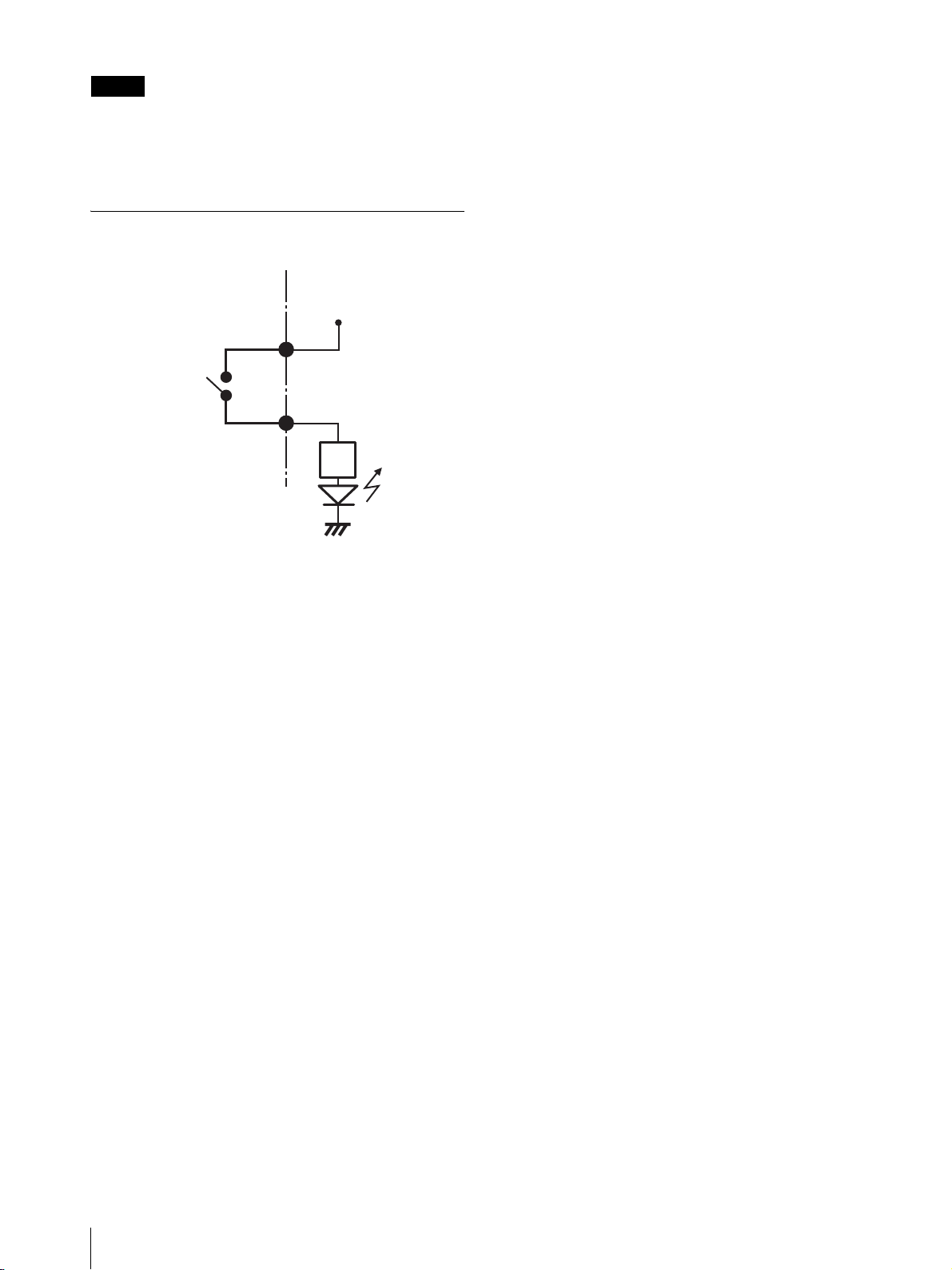
Note
When the wiring diagram 2 is used, the NSR is not
electrically isolated, so be sure to construct external
circuits that will not produce noise, excess voltage, or
overcurrents.
Wiring Diagram for Alarm Output
Inside of this unit Outside
3, 5, 7, 9, 11, 13,
15, 17pin
(ALARM OUT+)
Magnet relay
24 V AC/24 V DC,
1 A or less
2, 4, 6, 8, 10, 12,
14, 16pin
(ALARM OUT-)
5 V
Circuit example
GND
28
I/O Port
Page 29

安全のために
ソニー製品は安全に充分配慮して設計されています。しかし、電気製品は、まち
がった使いかたをすると、火災や感電などにより死亡や大けがなど人身事故につな
がることがあり、危険です。
事故を防ぐために次のことを必ずお守りください。
警告表示の意味
取扱説明書および製品では、次の
ような表示をしています。表示の
内容をよく理解してから本文をお
読みください。
安全のための注意事項を守る
この冊子の注意事項をよくお読みください。製品全般の注意事項が記されています。
定期点検をする
長期間、安全にお使いいただくために、定期点検をすることをおすすめします。点
検の内容や費用については、お買い上げ店またはソニーのサービス窓口にご相談く
ださい。
故障したら使わない
すぐに、お買い上げ店またはソニーのサービス窓口にご連絡ください。
万一、異常が起きたら
・ 煙が出たら
・ 異常な音、においがしたら
・ 内部に水、異物が入ったら
・ 製品を落としたり、キャビネットを破損したときは
m
a 電源を切る。
b 電源コードや接続コードを抜く。
c お買い上げ店またはソニーのサービス窓口に連絡する。
この表示の注意事項を守らないと、
火災や感電などにより死亡や大け
がなど人身事故につながることが
あります。
この表示の注意事項を守らないと、
感電やその他の事故によりけがを
したり周辺の物品に損害を与えた
りすることがあります。
注意を促す記号
行為を禁止する記号
・ 炎が出たら
m
z 電源プラグをコンセントから抜くか、ブレーカーを落とす。
z 大声で応援の人を呼ぶ。
z 水をかけるか、消火器を使って火を消す。
z 119 番へ通報する。
行為を指示する記号
29
Page 30
下記の注意を守らないと、火災や感電により死亡や大けが
につながることがあります。
電源コードを傷つけない
電源コードを傷つけると、火災や感電の原因となることがあります。
・ 設置時に、製品と壁やラック(棚)などの間に、はさみ込んだりしない。
・ 電源コードを加工したり、傷つけたりしない。
・ 重いものをのせたり、引っ張ったりしない。
・ 熱器具に近づけたり、加熱したりしない。
・ 電源コードを抜くときは、必ずプラグを持って抜く。
・ 電源コードを接続したまま、機器を移動しない。
・ 電源コードや電源プラグが傷んだり、コンセントの差し込み口がゆるいとき
は使用しない。
万一、電源コードが傷んだら、お買い上げ店に交換をご依頼ください。
内部を開けない
内部には電圧の高い部分があり、キャビネットや裏ぶたを開けたり改造したり
すると、火災や感電の原因となることがあります。内部の調整や設定、点検、
修理はお買い上げ店にご依頼ください。
日本国内で使用する場合
交流 100V でお使いください。
異なる電圧で使うと、火災や感電の原因となることがあります。
内部に水や異物を入れない
水や異物が入ると火災の原因となることがあります。
万一、水や異物が入ったときは、すぐに電源を切り、電源コードや接続コード
を抜いて、お買い上げ店にご相談ください。
水のある場所に設置しない
水が入ったり、ぬれたりすると、火災や感電の原因となることがあります。
雨天や降雪中、海岸や水辺での使用は特にご注意ください。
電源プラグの端子、および端子の取付け面にほこりが付着してい
る場合は、乾いた布でよく拭く。
そのまま使用すると火災の原因となります。
30
Page 31

下記の注意を守らないと、火災や感電により死亡や大け
がにつながることがあります。
電源プラグは、コンセントの奥まで確実に差し込む。
火災、故障の原因となることがあります。
31
Page 32

下記の注意を守らないと、けがをしたり周辺の物品に損害を与えること
があります。
油煙、湯気、湿気、ほこりの多い場所には設置しない
上記のような場所に設置すると、感電の原因となることがあります。
取扱説明書に記されている仕様条件以外の環境での使用は、感電の原因となる
ことがあります。
通風孔をふさがない
通風孔をふさぐと内部に熱がこもり、火災や故障の原因となることがありま
す。風通しをよくするために次の項目をお守リください。
・ 壁から 10cm 以上離して設置する。
・ 密閉された狭い場所に押し込めない。
・ 毛足の長い敷物(じゅうたんや布団など)の上に設置しない。
・ 布などで包まない。
・ あお向けや横倒し、逆さまにしない。
安全アースを接続する
安全アースを接続しないと、感電の原因となることがあります。
安全アースを取り付けることができない場合は、お買い上げ店にご相談くださ
い。
重い製品の運搬は二人以上で
重量のある機器の開梱・運搬は、けがや事故を防ぐため、必ず二人以上で行っ
てください。
転倒、移動防止の処理をする
大型の製品をラックに取り付け・取り外しするときは、転倒・移動防止の処理
をしないと、倒れたり、動いたりしてけがの原因となることがあります。
安定した姿勢で注意深く作業してください。
また、ラックの設置状況、強度を充分にお確かめください。
不安定な場所に設置しない
ぐらついた台の上や傾いたところに設置すると、倒れたり落下したりして、け
がの原因となることがあります。また、設置・取り付け場所の強度を充分にお
確かめください。
直射日光の当たる場所や熱器具の近くに設置・保管しない
内部の温度が上がり、火災や故障の原因となることがあります。
真夏の、窓を閉め切った自動車内では 50 ℃を越えることがありますので、ご
注意ください。
32
Page 33
下記の注意を守らないと、けがをしたり周辺の物品に損害を与えるこ
とがあります。
製品の上に乗らない、重い物を乗せない
倒れたり、落ちたり、壊れたりして、けがの原因となることがあります。
2台以上積み上げない
ラックを使用せずに2台以上積み上げると、機器が落下してけがの原因となる
ことがあります。
機器を移動する場合、あるいはお手入れの際は、電源を切って電
源プラグを抜く
電源を接続したままお手入れをすると、感電の原因となることがあります。
接続ケーブルなどもはずしてください。
長時間機器を使用しないときは、安全のため必ず電源プラグをコンセントから
抜いてください。
指定された電源コード、接続コードを使う
取扱説明書に記されている電源コード、接続コードを使わないと、感電や故障
の原因となることがあります。
ぬれた手で電源プラグをさわらない
ぬれた手で電源プラグを抜き差しすると、感電の原因となることがあります。
接続の際は電源を切る
電源コードや接続コードを接続するときは、電源を切ってください。感電や故
障の原因となることがあります。
ラックマウントレールに手や指をはさまない
ラックマウントした機器を収納するときおよび引き出すとき、ラックマウント
レールに手や指をはさみ、けがをすることがあります。
33
Page 34

©2006 Sony Corporation
目次
安全のために..............................................................................29
使用上のご注意 ........................................................................ 35
機能概要 .....................................................................................36
必要なシステム ........................................................................ 37
箱の中身を確認する ................................................................38
各部の名称 .................................................................................39
前面(カバーを開けた状態) ............................... 39
背面 .................................................................... 40
設置する .....................................................................................41
ラックに設置しない場合 .................................... 41
本機をラックに設置する場合 ............................. 42
モニターを接続する ........................................... 44
キーボードとマウス、リモコン(RM-NS10)を接
続する ................................................................. 44
電源コードを接続する ........................................ 44
ネットワークケーブルを接続する ...................... 44
ネットワークカメラを接続する .......................... 45
その他の機器を接続する .................................... 45
リモートクライアントを接続する ...................... 45
電源を入れる/切る ................................................................46
電源を入れる ...................................................... 46
電源を切る ..........................................................46
初めて起動したときの操作(簡単な初期セットアップ) ...
46
基本設定 ............................................................. 46
カメラ IP 設定と NSR への登録 ......................... 49
データボリュームの再構築(RAID の変更) ...................51
STATUS LED の見かた ......................................................53
その他 .........................................................................................54
ソフトウェア使用許諾書 .................................... 54
GPL/LGPL について .......................................... 54
MPEG-4 Video Patent Portfolio License
について ............................................................. 55
故障かな?と思ったら ........................................ 55
I/O ポートについて ................................................................57
I/O ポートのピン配列 ........................................ 57
I/O ポートの接続方法 ........................................ 57
センサー入力への配線図 1 ................................. 57
センサー入力への配線図 2 ................................. 57
アラーム出力への配線図 .................................... 58
商標について
・ “IPELA” および は、ソニー株式会社
の商標です。
・ Microsoft、Windows は、米国 Microsoft
Corporation の米国およびその他の国における登録商
標または商標です。
・ イーサネットは、富士ゼロックス株式会社の登録商標で
す。
・ その他、本書に記載されているシステム名、製品名、会
社名は一般に各開発メーカーの登録商標または商標です。
・ 本機をお使いになる前に、必ず本書の使用許諾契約書を
お読みください。
なお、本文中では、®、™ マークは明記していません。
・ 権利者の許諾を得ることなく、本機に付属のソフト
ウェアおよび取扱説明書の内容の全部または一部を
複製すること、およびソフトウェアを賃貸すること
は、著作権法上禁止されております。
・ 本機、および本機に付属のソフトウェアを使用した
ことによって生じた損害、逸失利益、および第三者
からのいかなる請求等につきましても、当社は一切
その責任を負いかねます。
・ 本機の保証条件は、同梱の当社規定の保証書の規定
をご参照ください。
・ 本機に付属のソフトウェアは、本機以外には使用で
きません。
・ ソニーが配布した本機用のソフトウェア以外のソフ
トウェアをインストールすることはできません。
・ 本機、および本機に付属のソフトウェアの仕様は、
改良のため予告なく変更することがありますが、ご
容赦ください。
・ 本機では、パスワードの保存等は MD5 による高度
なセキュリティーを使用しています。
録画内容の補償に関する免責事項
本機の不具合など何らかの原因で記録ができなかった場
合、不具合・修理など何らかの原因で記録内容が破損、
消滅した場合等、いかなる場合においても記録内容の補
償およびそれに付随するあらゆる損害について、当社は
一切の責任を負いかねます。また、いかなる場合におい
ても、当社にて記録内容の修復、復元、複製等はいたし
ません。あらかじめご了承ください。
34
本書をお読みになる前に
『安全のために』(別紙)を必ずお読みください。
Page 35

使用上のご注意
安全上のご注意
・ 本機の電源仕様は以下のとおりです。必ず以下の仕様に
適合する電源を使用してください。
- 電圧:AC 100-127 V/200-240 V
- 電流:8/4 A
- 周波数:50/60 Hz
・ 付属の電源コードを使用し、束ねたり、タコ足配線しな
いでください。定格をこえた電流が流れると、火災など
の原因となります。
・ 使用するコンセントや電源コードが正しくアースされて
いることを確認してください。
・ カバー類を外した状態で使用しないでください。カバー
類を外した状態で使用すると、火災、感電の原因となる
ことがあります。カバー類を外す必要があるときは、必
ずお買い上げ店に依頼してください。
設置上のご注意
使用・保管場所
長期間ご愛用いただくために、次のような場所での使用
および保管は避けてください。
・ 極端に暑いところや寒いところ(使用温度は 5 ℃~
40 ℃です。)
・ 直射日光が長時間あたるところや暖房器具の近く(真
夏、窓を閉め切った自動車内では 50 ℃を超えることが
ありますのでご注意ください。)
・ 湿気・ほこりの多いところ
・ 激しい振動があるところ
・ 強い磁気の発生するものの近く
・ 強力な磁気を発生するテレビ、ラジオの送信所の近く
通風孔をふさがない
・ 本機内の温度の上昇を防ぐため、本機の側面にある通風
孔をふさがないでください。本機の両側面、後面、上面
は、壁や天井から 10 cm 以上離してください。
・ 本機を密閉された箱に入れて使用しないでください。
・ 本機背面のファンの通風孔付近に、ケーブルやその他の
障害物がこないように設置してください。通風孔をふさ
ぐと内部に熱がこもり、火災や故障の原因となることが
あります。
・ 本機をラックに設置して使用するときも、本機背面の
ファン、前面の通気孔付近に、ケーブルやその他の障害
物がこないように設置してください。また、動作環境が
上記の条件を満たす場所に設置してください。
水平位置で使用してください
・ 本機は水平平面上で動作するように設計されています。
・ 傾いた場所に設置しないでください。強い衝撃を与えな
いでください。
・ 落としたりして強い衝撃を与えると故障することがあり
ます。
・ 本機をラックに設置するときは、水平が保てるように取
り付けてください。高さを合わせないで取り付けると、
誤動作の原因となります。また、本機をラックに取り付
けたときに、ラックの重量バランスが崩れて転倒するこ
とを防ぐため、ラックに転倒防止金具などを取り付ける
ことをおすすめします。
お手入れについて
・ お手入れをする前に、電源プラグをコンセントから抜い
てください。
・ キャビネットやパネルの汚れは、乾いた柔らかい布で軽
くふき取ってください。汚れがひどいときは、中性洗剤
溶液を少し含ませた布で汚れをふき取り、乾いた布で仕
上げてください。
・ アルコール、シンナー、ベンジンや殺虫剤など、揮発性
のものをかけると、変質したり塗料がはげることがあり
ます。
・ 本機前面の通風孔にほこりがたまることがあります。そ
の場合は、衝撃・振動を与えないように注意して除去し
てください。
輸送のときは
付属のカートン、または同等品で梱包し、急激な衝撃を
与えないようにご注意ください。
HDD 内蔵機器に対する注意事項
本機には、ハードディスクドライブ(以下 HDD と称す
る)が搭載されています。HDD は精密部品であり、衝
撃・振動・静電気・温度・湿度が原因で故障したり、
HDD 内のデータが破損する恐れがあります。本機を設
置・使用するときは、以下の注意事項をよくお読みのう
え、慎重に取り扱ってください。
衝撃・振動を与えない
衝撃・振動が加わると HDD が故障あるいは HDD 内の
データが破損される恐れがあります。
・ 本機を輸送する場合は、指定の梱包材料で梱包してくだ
さい。台車などで搬送する場合は、振動の少ない台車を
使用してください。過度な衝撃・振動が加わると HDD
が故障するおそれがあります。
・ 通電中は本機を移動しないでください。本機をラックか
ら出し入れするときも、必ず電源をオフにした状態で
行ってください。
JP
使用上のご注意
35
Page 36

・ ラック内にあるすべての HDD 搭載機器に衝撃を与えな
いでください。
・ 本機をラックから出し入れするとき、ラック内に通電中
の HDD 搭載機器がある場合は、必ずその機器の電源を
オフにしてください。
・ 本機の外装を取り外さないでください。
・ 本機を床などに置くときは、本機の底に必ず指定のゴム
脚がついている状態で、静かに降ろしてください。脚が
付いていない場合は、脚を取り付けてから置いてくださ
い。
・ 振動を発生する機器の近くには置かないでください。
電源オフ後 30 秒間は作業しない
電源をオフにした後もしばらくの間は、HDD 内のディス
クは慣性で回転しており、ヘッドは不安定な状態にあり
ます。この期間は、通電中以上に衝撃・振動に弱い状態
です。電源オフ後、最低 30 秒間は軽い衝撃も与えないよ
うにご注意ください。30 秒以上経過すれば、(ディスク
が静止するので)作業を開始できます。
温度・湿度に関するご注意
適正範囲内の温度・湿度のある場所で、保管・使用して
ください。
動作温度:5 ~ 40 ℃
動作湿度:20 ~ 80%(最大湿球温度 30 ℃、結露の
ないこと)
保存温度:-20 ~ +60 ℃
保存湿度:20 ~ 90%(最大湿球温度 40 ℃、結露の
ないこと)
HDD に不良症状が現れた場合
万一、本機の HDD が故障した(不良症状が現れた)と思
われる場合でも、本機の取り扱いは、上記と同様に行っ
てください。不良内容の確認や不良解析を行うまでの損
傷の拡大を防ぎます。
HDD の交換
HDD、ファン、バッテリーは消耗品です。常温でのご使
用の場合、2 ~ 3 年を目安に交換してください。ただし、
この時間はあくまでも交換の目安であり、部品の寿命を
保証するものではありません。交換の際はお買い上げ店
にご相談ください。
機能概要
NSR シリーズはネットワークカメラに対応したハード
ディスクレコーダーです。JPEG または MPEG-4 によ
り、ネットワークカメラの画像をネットワーク経由でモ
ニタリングしたり、記録することができます。また、記
録した画像を再生、検索することもできますので、監視
システムとして幅広い用途にお使いいただけます。
対応ネットワークカメラの遠隔操作が可能
パン(左右)・チルト(上下)・ズーム(拡大)に対応し
たカメラであれば、カメラの動作を制御できます。
アナログカメラにも対応
別売のカメラサーバー SNT-V704 を使用することによ
り、アナログカメラの画像もネットワーク経由でモニタ
リングし、記録することが可能です。
大容量ハードディスクに長時間記録
大容量ハードディスクを内蔵しています。NSR-100 は最
大約 920 GB
記録容量を持ち、長時間記録ができます。NSR-100 の場
合、16 台のカメラ画像を 1 fps2)で(VGA、JPEG:1
フレームあたり約 31 KB、
1 日 15 時間記録の場合)約 1 か月分の記録が可能です
1) 上記データ記録容量には内蔵ソフトウェアが管理するデータ
ベースの容量を含みます。
2) fps:フレーム毎秒。1 fps は 1 秒間に 1 フレームの画像を
記録。
3) RAID 0 設定時。
省スペースの 2U、19 インチラックマウントタイプ
オプション(別売り)のラックマウントキットを使うと、
EIA STANDARD(ユニバーサルピッチ)の 19 インチ
ラックに設置できます。
最大 480 fps(VGA、JPEG)での高画質記録
NSR-100 は最大 64 台(NSR-50 は 32 台)のカメラを
接続できます。また、NSR-100 では、トータルフレーム
レート 480 fps*(NSR-50 は 240 fps)で、VGA
(640 × 480)、JPEG 画質(1 フレームあたり約 31 KB)
の画像を記録できますので、自然でなめらかな高画質記録
を実現します。
1)
、NSR-50 は最大約 460 GB1)のデータ
3)
。
36
*カメラ 16 台接続時の合計フレームレート最大値。1 台あたり
のフレームレートは 30 fps。ハードディスク内のフラグメン
テーション(断片化)により低下する場合があります。値は、
弊社内環境での測定によるものです。お客様の環境によって性
能は変化するため、必ずしもこの値を保証するものではありま
せん。
機能概要
Page 37

高信頼性の実現
NSR-100 は RAID 0、1+0、5 に、NSR-50 はスパニング
*
と RAID 1 に対応し、高信頼性を実現しています。RAID 1、
1+0、5 で使用した場合、仮にハードディスクのうち 1 台
が故障した場合でも、システムの運用が継続できます。ま
た、本体内に内蔵されたフラッシュメモリーにシステムソフ
トウェアおよび各種設定を記憶することにより、システムソ
フトウェアに異常が発生した場合でも、迅速なシステムの復
旧が可能です。さらに、UPS(無停電電源装置)
**
にも対
応し、システムとしての高い信頼性を実現しています。
* スパニング:複数のハードディスクを仮想的に 1 台のハー
ドディスクとして使用する機能。
** 弊社推奨製品をご利用ください。
メモ
NSR-100 を RAID 0、NSR-50 をスパニングで使用した
場合、データの冗長性はありません。また、各 RAID レ
ベルによって記録容量は異なります。
その他の機能
・ 1 画面 1 画像から最大 8 × 8(64 画面)までの画面レ
イアウトに対応しています。
・ マニュアル記録、スケジュール記録、アラーム記録など
の多彩な記録モードをサポートしています。
1)
・ 動体検知機能
(Video Motion Detection(レコー
ダー))を標準装備しています。
・ カメラ名、日時、アラームなどをキーにして、記録画像
を検索できます。
・ 画像の特定部分を覆い隠し、プライバシー保護などに利
用できるダイナミックマスキング機能
2)
を標準搭載し
ています。マスキングエリアはパン(左右)、チルト
(上下)やズーム(拡大)にも追従します。
・ カメラから配信される画像処理結果である物体情報のメ
3)
タデータを用いた各種フィルタリング
を行うことに
よって、高度なアラーム処理が可能となりました。記録
済みのメタデータに対してもフィルタリングが可能なた
め、記録後に、気になる部分について検索できます。
・ 対応ネットワークカメラからの音声の記録/再生
3)
に
も対応しています。
1) 接続するカメラの台数によっては、機能に制限があります。
2) 接続するカメラの機種によっては、機能に制限があります。
3) メタデータを使用して動体、不動体検知を行う場合は、動体
検知メタデータに対応しているカメラが必要です。メタデー
タの利用は、32 台までサポートしています。
4) 別売のアクティブスピーカーが必要です。
必要なシステム
本機を操作するために必要なハードウェアは以下のとお
りです。
・ ソニー製ネットワークカメラ
本機で使用できるソニー製ネットワークカメラについて
は、お買い上げ店にお問い合わせください。
・ モニター
・ USB キーボード
・ USB マウス
・ ネットワークスイッチ
・ 1000 Base-T/100 Base-TX/10 Base-T ケーブル
・ CF(CompactFlash)または USB メモリー
1) 本機で使用できるモニターについては、お買い上げ店にお問
い合わせください。
「Generic」タイプとして選択できるモニターは、以下のとお
りです。
各行の最後は周波数を示しています。
- Generic LCD Display; LCD Panel 1024x768; 40-70
- Generic LCD Display; LCD Panel 1280x1024; 50-75
- Generic LCD Display; LCD Panel 1600x1200; 60
- Generic CRT Display; Monitor 1024x768; 50-70
- Generic CRT Display; Monitor 1280x1024; 50-90
- Generic CRT Display; Monitor 1600x1200; 50-90
指定できる解像度は、以下のとおりです。
- XGA(1024 × 768)
- SXGA(1280 × 1024)
- UXGA(1600 × 1200)
2) USB キーボードは、ケーブル接続タイプをお使いください。
無線接続や赤外線接続タイプの USB キーボードでは動作し
ない場合があります。また、拡張ボタンなど、標準以外の機
能も動作しない場合があります。
3) USB マウスは、ケーブル接続タイプをお使いください。無線
接続や赤外線接続タイプの USB マウスでは動作しない場合
があります。また、3 ボタンやホイール以外の機能も動作し
ない場合があります。
4) ログなどのシステム情報を取得するために必要です。
- CF は、あらかじめ VFAT にフォーマットされているもの
- USB メモリーは、一般的な USB マスストレージに対応し
1)
2)
3)
4)
をお使いください。
ています。
重要
本書では、本機の設置と初期設定について説明していま
す。本機の詳細な設定については、本機に付属の NSR
Series Manual, Tool & Source Codes CD に収録されて
いる『ユーザーガイド』(PDF)を参照してください。
必要なシステム
37
Page 38

箱の中身を確認する
パッケージを開けたら、以下のものが揃っているかお確
かめください。付属品の中に欠けているものがあるとき
は、お買い上げ店にご連絡ください。
・ NSR-100/50 サーベイランスレコーダー 本体(1)
・ 電源コード(1)
・ フロントパネルキー(2)
・ 設置説明書(本書)(1)
・ リモコン操作カード(1)
・ NSR Series Recovery CD(1)
・ NSR Series Manual, Tool & Source Codes CD(1)
・ 安全のために(1)
・ 安全規格文(1)
・ 保証書(冊子)(1)
・ 保証シート(1)
・ ゴム足(4)
メモ
・ 上記以外に、説明書や書類などが同梱されている場合が
あります。
・ 箱と梱包材は、本機を移動したり輸送したりするときに
必要です。捨てないで必ず保管してください。
・ ラックマウントキットはオプション(別売り)です。
・ NSR Series Manual, Tool & Source Codes CD には
以下が含まれています。
Manual フォルダ:ユーザーガイド、リモコン操作
カードデータ(多言語版)
SourceCode フォルダ:GPL/LGPL 適用ソフトウェ
アソースコード
Tool:リモートクライアントソフトウェア(RealShot
Manager)、CAM ファイル再生用アプリケー
ション(Media File Player)とそのユーザー
ガイド
箱の中身を確認する
38
Page 39

各部の名称
708q
9q
q
q
q
前面(カバーを開けた状態)
NSR-100/50
123 4 5 6
POWER 1 2 3NETWORK 1 2 3 4HDD 1 2 3 4 ERRORSTATUS REC
f
g
d
s
a
A POWER LED
起動中は緑色とアンバー色が交互に点灯します。
起動が完了すると緑色に点灯します。
スタンバイモードのときはアンバー色に点灯します。
B NETWORK LED(1 ~ 3)
背面の LAN コネクター(1 ~ 3)にそれぞれアク
ティビティがあるときに緑色に点灯します。
C HDD LED
内蔵ハードディスクのアクセス時に緑色に点滅しま
す。 ハードディスクにエラーが発生したときはアン
バー色に点灯します。
D STATUS LED(1 ~ 4)
本機の起動時に、1→ 2 → 3 → 4 の順で点灯します。
また、エラーが発生したときには、ERROR LED が
点灯/点滅するとともに STATUS LED が点灯し、
エラーの内容を表示します。
詳細は、「STATUS LED の見かた」 (53 ページ)を
参照してください。
E ERROR LED
エラーが発生した場合に点灯/点滅します。
F REC LED
画像の記録中に点灯します。
G DVD/CD ドライブ
本機の内蔵ハードディスクに保存されているデータ
を、DVD、CD メディアに記録できます。
H USB コネクター
USB キーボード、USB マウス、USB フラッシュメ
モリー、リモコン(RM-NS10)を接続します。
I マイク入力端子
外部機器からの音声を入力します。
*
J オーディオ出力端子(L/R)
音声を出力します。
K ビデオ出力端子
ビデオデッキなどを接続します。
常にモニターコネクター 1 と同じ映像が表示されま
す。
L モニターコネクター 1
モニターを接続します。
M コンパクトフラッシュカードスロット
本機の内蔵ハードディスクに保存されている設定デー
タを、コンパクトフラッシュカードに記録できます。
N 鍵穴
付属の HDD トレイ施錠鍵を使って、フロントベゼ
ルをロックします。ロック時には、フロントベゼル
は引き出せません。また、フロントベゼルを引き出
した状態でロックしないでください。
ロック時とロック解除時の鍵穴の位置は、以下のと
おりです。
ロック時 ロック解除時
*使用できるメディアについては、本機に付属の NSR
Series Manual, Tool & Source Codes CD に収
録されている『ユーザーガイド』(PDF)を参照し
てください。
各部の名称
39
Page 40

O 通風孔
9q
0q
q
q
本体前面から背面へのエアフローの入り口です。
通風孔をふさいだり、通風孔の内側のメッシュにほ
こりがたまったりして、エアフローが妨げられない
背面
NSR-100/50
231 654 7 8
ようにしてください。エアフローが妨げられると内
部に熱がこもり、火災や故障の原因となることがあ
ります。
*この機能は、現在サポートされておりません。
f
A ファン
ファンの通風孔をふさがないように注意してくださ
い。通風孔をふさぐと内部に熱がこもり、火災や故
障の原因となることがあります。
B 電源スイッチ
○の方に押すと、電源が入ります。
C ビデオ出力端子
ビデオデッキなどを接続します。
常にモニターコネクター 1 と同じ映像が表示されま
す。
D S 映像出力端子
S 端子を装備したビデオデッキなどを接続します。
常にモニターコネクター 1 と同じ映像が表示されま
す。
E シリアル(RS-232C)コネクター
UPS(無停電電源装置)のコントロール系を接続し
ます。
F センサー入力端子
センサーを接続します。
接続のしかたとセンサー入力への配線図については、
「I/O ポートについて」 (57 ページ)を参照してくだ
さい。
G アラーム出力端子
アラームを接続します。
接続のしかたとアラーム出力への配線図については、
「I/O ポートについて」 (57 ページ)を参照してくだ
さい。
d
s
H マイク入力端子
I SCSI コネクター
a
*
マイクからの音声を入力します。
*
ハードディスクシステム(SCSI 機器)を接続しま
す。
J USB コネクター
USB キーボード、USB マウス、USB フラッシュメ
モリー、リモコン(RM-NS10)を接続します。
K LAN コネクター(1 ~ 3)
10 Base-T/100 Base-TX/1000 Base-T のネット
ワークケーブルを接続します。
LAN1:ネットワークカメラ
LAN2:リモートクライアント
LAN3:外部ストレージデバイス
**
L モニターコネクター(1、2)
モニターを接続します。
M オーディオ出力端子 (L/R)
音声を出力します。
N 電源コネクター
付属の電源コードを接続します。
* この機能は、現在サポートされておりません。
** ソフトウェアのバージョンによっては、サポートされており
ません。お買い上げ店にご確認ください。
40
各部の名称
Page 41

フロントベゼルを開けたとき
設置する
設置場所のスペースや強度を充分確認してから、本機を
設置し、電源ケーブルを接続します。
本機の質量は、NSR-100 が約 14 kg、NSR-50 が約 12
kg で、大きさは以下のとおりです。
87 mm
430 mm
上から見たところ
417 mm
494 mm
117 mm
106 mm
102 mm
123 mm
377 mm
479 mm
377 mm
付属のラックマウントキットを使用すると、本機をラッ
クに据え付けることができます。
ラックに設置しない場合
430 mm
フロントベゼルを閉じたとき
417 mm
40 mm
377 mm
417 mm
付属のゴム足を本機に取り付ける。
底面が見えるようにして、立てて置き、ゴム足の接着面
を底面の四隅に貼り付けます。
図の位置を参考にして貼ってください。
シールをはがす
ゴム足
本体底面
設置する
41
Page 42

本機をラックに設置する場合
オプション(別売り)のラックマウントキットを使用し
て、本機をラックマウントに設置します。
メモ
インナーレールは本機に、レールアセンブリーは
ラックに取り付けます。
ご注意
・ 本機のオプション(別売り)以外のラックマウントキッ
トを使用すると、火災や感電、けがなどの原因となりま
す。危険ですのでおやめください。
・ 本機をラックに設置した場合、本機の上に重い物を載せ
ないでください。
・ あらかじめ本機を取り付ける位置を決め、ラックにフェ
ルトペンなどで印を付けておくことをおすすめします。
ラックの高さを合わせないで本機を取り付けると、誤動
作の原因となりますのでご注意ください。
インナーレールを取り出す
レールアセンブリーからインナーレールを取り出します。
1
レールアセンブリーからインナーレールを、止まる
位置まで引き出す。
レールアセンブリーの裏側
本機の準備をする
ラック取り付け金具とインナーレールを取り付けます。
1
付属の皿ネジを使って、本機側面の前側にラック取
り付け金具を取り付ける。
ラック取り付け
金具
皿ネジ
2
付属のナベネジを使って、インナーレールを取り付
ける。
インナーレール
レールアセンブリー
2
レールアセンブリーを裏返し、緑色のタブを矢印の
方向に引いてロックを解除しながら、インナーレー
ルを引き抜く。
緑色のタブ
3
同様にして、もう 1 本のレールアセンブリーからイン
ナーレールを引き抜く。
緑色のタブ
緑色のタブ
ご注意
付属以外のネジを使用すると、故障の原因となりま
す。レールの取り付けには、必ず付属のネジを使用
してください。
ラックの準備をする
ラックにレールを取り付けます。
1
レールを取り付ける位置を決める。
レールを取り付ける位置に、フェルトペンなどで印
を付けておくことをおすすめします。
レール
ナベネジ
42
設置する
Page 43
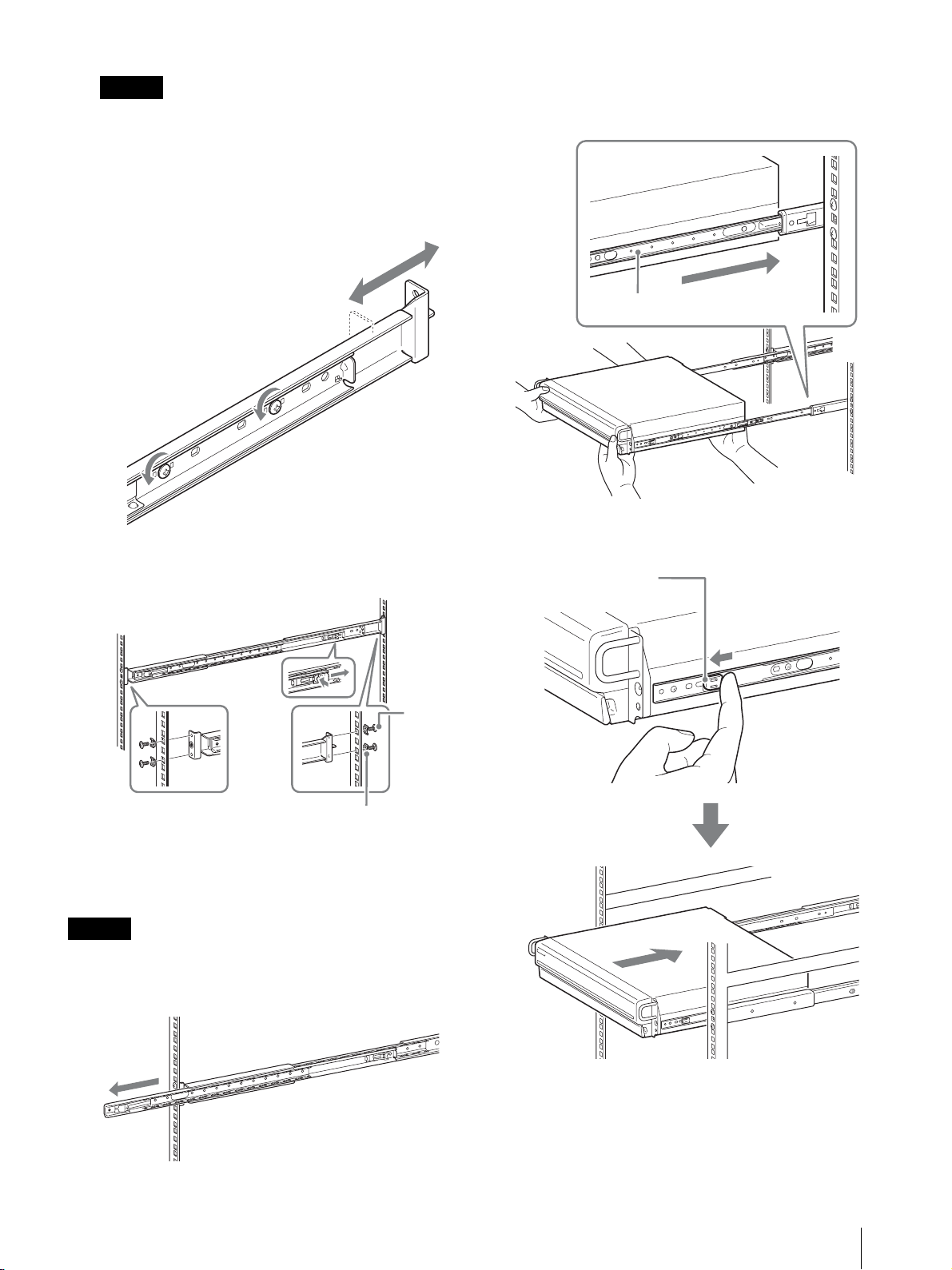
ご注意
レールの高さを合わせないで本機を取り付けると、
誤動作の原因となりますのでご注意ください。
2
ラックにレールを取り付ける。
1 お使いのラックに合わせて、レールの長さを調
節する。
2 付属のトラスネジとワッシャーを使って、前側
と後ろ側のフレームにレールを固定する。
2
本機を持ち上げ、インナーレールをスライドレール
の溝(白い部分)に載せて、止まるところまでスラ
イドさせる。
インナーレール
3
緑色のタブを手前に引いてロックを解除しながら、
本機をラックの奥までスライドさせる。
緑色のタブ
トラス
ネジ
ワッシャー
本機をラックに取り付ける
本機をラックに入れて固定します。
ご注意
けがや事故を防ぐため、必ず二人以上で行ってください。
1
レールアセンブリーからスライドレールを引き出す。
設置する
43
Page 44
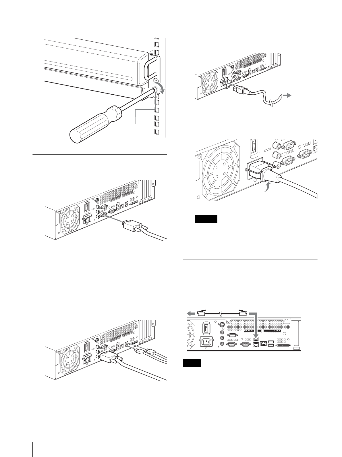
4
付属のナべネジを使って、本機を固定する。
ナベネジ
モニターを接続する
本機背面のモニターコネクター 1 にモニターを接続する。
電源コードを接続する
1
付属の電源コードを接続する。
1
2
電源ケーブル固定金具をコネクターにはめて、電源
ケーブルが抜けないように固定する。
コンセントへ
キーボードとマウス、リモコン
(RM-NS10)を接続する
1
本機背面(または前面)の USB コネクターにキー
ボードを接続する。
2
USB コネクターにマウスやリモコン(RM-NS10)
を接続する。
ご注意
設置の前には「安全上のご注意」 (35 ページ)をよ
くお読みください。NSR を複数台ご使用になる場合
には、電源の容量にもお気を付けください。
ネットワークケーブルを接続する
ネットワークケーブルを接続します。
ネットワークケーブルを、本機の LAN コネクターとネッ
トワークスイッチに接続する。
メモ
本機の工場出荷時の IP アドレスは、以下のように設定され
ています。
・ LAN コネクター 1:「192.168.0.1」
・ LAN コネクター 2:「192.168.1.1」
・ LAN コネクター 3:「192.168.2.1」
44
設置する
Page 45

工場出荷時の IP アドレスを変更したいときは、本機に付
属の NSR Series Manual, Tool & Source Codes CD に
収録されている『ユーザーガイド』(PDF)を参照してく
ださい。
ネットワークカメラを接続する
ネットワークカメラを接続します。
UPS(無停電電源装置)を接続する
1
UPS を電源に接続する。
2
付属の電源コードを使って、本機と UPS を接続する。
3
UPS 専用のシリアルケーブルを使って、本機と UPS
を背面のシリアルコネクターに接続する。
ネットワークケーブルを本機の LAN コネクター 1 とネッ
トワークスイッチに接続し、ネットワークケーブルを
ネットワークスイッチとネットワークカメラに接続する。
ネットワーク
スイッチ
ネットワークカメラ
その他の機器を接続する
コンパクトフラッシュカード(CF カード)
を使用する
コンパクトフラッシュカードを図の向きで奥まで差し込
む。
ラベル面を上にして、▲印の方向に奥まで差し込んでく
ださい。
POWER 1 23LAN 1 2 34HDD 1 2 3 4 ERRORSTATUS REC
リモートクライアントを接続する
リモートクライアントが必要な場合は、本機に付属の
RealShot Manager コントローラーを使用できます。
RealShot Manager コントローラーは、Windows コン
ピューターで動作します。推奨スペックなどの詳細につ
いては、RealShot Manager コントローラーのインス
トールアーカイブに収められているリリースノートを参
照してください。なお、RealShot Manager は、本機に
付属のものを使用してください。
1
ネットワークケーブルを、本機の LAN コネクター 2
とネットワークスイッチに接続する。
2
ネットワークケーブルを、RealShot Manager コン
トローラーソフトウェアがインストールされている
コンピューターに接続する。
ネットワーク
スイッチ
NSR へ
RealShot Manager
コントローラーソフト
Windows PC
ウェア
コンパクトフラッシュカードを取り出すときは、スロッ
ト左端の取り出しボタンを押してください。
ご注意
コンパクトフラッシュカードを取り出す際に、コンパク
トフラッシュカードが勢いよく飛び出すことがあります
ので、注意してください。
メモ
・ RealShot Manager コントローラーソフトウェアのインス
トール方法その他については、本機に付属の NSR Series
Manual, Tool & Source Codes CD をご覧ください。
・ NSR のリモートコントローラーとして RealShot
Manager を使う場合は、RSM のインストール時に
[Controller]を選択してください。
・ NSR 本体の RealShot Manager のサーバー機能の接続
ポートの初期値は「8081」です。接続ポートは、NSR
から変更できます。
・ ユーザーエリアのネットワークに接続する場合も、
LAN コネクター 2 に接続してください。
設置する
45
Page 46

電源を入れる/切る
電源を入れる
本機背面の電源スイッチを○の方へ押す。
初めて起動したときの操
作(簡単な初期セット
アップ)
ご注意
この取扱説明書では、画面に表示される項目の一部を日
本語で説明しています。
本機前面の POWER LED が緑色になります。
メモ
・ 電源を入れた直後(約 2 秒間)にファンの大きな音が
しますが、これは故障ではありません。
・ 初めて電源を入れたときは、システムの初期設定ツール
が自動的に実行されます。本機に付属の NSR Series
Manual, Tool & Source Codes CD に収録されている
『ユーザーガイド』(PDF)を参照しながら設定を行っ
てください。
・ 前回異常終了した場合は、起動するまでに時間がかかる
ことがあります。
電源を切る
1
NSR にログオンし、画面上部の[システム]をク
リックする。
「システム」画面が表示されます。
2
[シャットダウン]をクリックする。
確認のメッセージが表示されます。
3
[OK]をクリックする。
システムが終了し、電源が切れます。
基本設定
1
本機に USB キーボードと USB マウスを接続し、電源
を入れる。
以下の画面が表示され、ハードウェア起動のプログ
レスバーが表示されます。
続いて以下の画面が表示され、ソフトウェア起動の
プログレスバーが表示されます。
電源を入れる/切る / 初めて起動したときの操作(簡単な初期セットアップ)
46
本機が起動し、システム設定画面(Setup Wizard)
が表示されます。
Page 47

2
[次へ]をクリックする。
「Select Language」画面が表示されます。
3
画面に表示する言語を選択し、[次へ]をクリックす
る。
6
日付と時刻を設定する地域を選択し、[次へ]をク
リックする。
注: 夏時間の有効/無効の指定はありません。夏時
間があるタイムゾーンを選ぶと、自動的に夏時
間調整が行われます。
「Date and Time」画面が表示されます。
7
日付と時刻を確認し、ずれている場合は正しい日付
と時刻を設定して、[次へ]をクリックする。
「EULA」画面が表示されます。
4
ソフトウェア使用許諾書をよく読み、[承諾]を
チェックし、[次へ]をクリックする。
「Keyboard Layout」画面が表示されます。
5
本機に接続している USB キーボードの言語を選択
し、[次へ]をクリックする。
「General Network Setting」画面が表示されます。
8
以下の手順でネットワークの設定を行う。
(1)「General Network Setting」画面に各サー
バーの IP アドレスを入力し、[次へ]をクリッ
クする。
Primary DNS
プライマリ DNS(Domain Name Server)の
IP アドレスを入力します。プライマリ DNS が
ない場合や必要としない場合は、入力しないで
ください。
「Time Zone」画面が表示されます。
Secondary DNS
セカンダリ DNS の IP アドレスを入力します。
セカンダリ DNS がない場合や必要としない場
合は、入力しないでください。
初めて起動したときの操作(簡単な初期セットアップ)
47
Page 48

Default Gateway
デフォルトゲートウェイの IP アドレスを入力し
ます。ローカルネットワークのみの場合や他の
ネットワークへの接続が必要ない場合は、入力
しないでください。
「Network Device #1」画面が表示されます。
(2)LAN ポートそれぞれについて「Network
Device」の設定を行う。
3 つの LAN ポート(LAN1、LAN2、LAN3)
を設定します。
ご使用環境に応じて設定し、それぞれの設定画
面で[次へ]をクリックします。
メモ
各 LAN ポートに以下の機器を接続してくださ
い。
LAN1:ネットワークカメラ
LAN2:リモートクライアント
LAN3:外部ストレージデバイス(ソフトウエ
アバージョンによってはサポートされておりま
せん。お買い上げ店にご確認ください。)
・ IP アドレスの割り当て規則上、禁止されてい
るアドレスを設定しても、システムには反映
されません。
例: 224.0.0.0 ~ 255.255.255.255
0.0.0.0
127.0.0.1 など
Netmask
サブネットマスクを入力します。
メモ
ネットワークデバイス設定のデフォルト値は、
以下のとおりです。
IP Address: 192.168.[0/1/2]
Netmask: 255.255.255.0
*ネットワークデバイス[#1/#2/#3]ごとの設定値
です。
「Monitor Model」画面が表示されます。
9
モニターポートごとに画面サイズを選択し、[次へ]
をクリックする。
本機に 2 台のモニターを接続して使用する場合は、
[Dual Head]をクリックすると、2 番目のモニター
の設定画面に移行します。
お使いのモニターに合わせて、モニタータイプと解
像度を選択してください。
*
.1
DHCP を利用してアドレス設定を自動取得する
場合
[DHCP]を選択します。
アドレス設定を手動で行う場合
(1)[Static]をクリックする。
(2)以下のアドレスを入力する。
IP Address
IP アドレスを入力します。
ご注意
・ IP アドレスは、同じネットワーク上に同じ値
を使用しているマシンが存在しないことを確
認してから、入力してください。同じ値を使
用しているマシンがすでに存在していても、
エラーメッセージは表示されません。複数の
マシンで同じ値を使用すると、誤動作の原因
になりますのでご注意ください。
メモ
・ モニター設定のデフォルト値は、以下のとおりで
す。
Generic LCD Display; LCD Panel 1600x1200;
31.5-90;60
Resolution 1024x768
・ ほとんどのモニターは[Generic Monitor]で動
作しますが、必要に応じて[Others]からモニ
タータイプを選択してください。
ご注意
2 番目のモニターを設定した場合は、2 番目のモニ
ターを接続した状態での再起動が必要です。
「Video Settings」画面が表示されます。
初めて起動したときの操作(簡単な初期セットアップ)
48
Page 49

10
お使いの Video Setting に合わせて[NTSC]または
[PAL]を選択し、[次へ]をクリックする。
日本国内では、一般的に NTSC が使用されています。
「Host Name」画面が表示されます。
11
以下の項目を設定し、[次へ]をクリックする。
13
[終了]をクリックする。
しばらくすると、自動的に本機が再起動します。
カメラ IP 設定と NSR への登録
再起動後、ログオン画面が表示されます。
続いて、カメラの IP アドレスを設定し、NSR に登録しま
す。
1
ユーザーとパスワードを入力して[ログオン]をク
リックする。
初期設定ユーザー: admin
初期パスワード: admin
Host Name
本機のホスト名を入力します。
メモ
使用できる文字は、英数字、_(アンダーバー)、-
(マイナス)です。
Domain Name
使用する環境のネットワークドメイン名を入力しま
す。
例: xxx.sony.co.jp
本機を DNS に登録しない場合は、デフォルトのまま
で問題ありません。
「Summary」画面が表示されます。
12
設定内容を確認し、[次へ]をクリックする。
「基本設定」画面の「カメラ」画面が表示されます。
2
[カメラ IP 設定]をクリックする。
すでにカメラの IP アドレスが設定されている場合
は、[カメラ一括登録]をクリックして、手順 5 に進
んでください。
「カメラ IP 設定」画面が表示されます。
「Warning」画面が表示されます。
初めて起動したときの操作(簡単な初期セットアップ)
49
Page 50

3
以下の設定を行う。
「カメラ IP 設定」画面では、同一ネットワーク上の
カメラを MAC アドレスで検索し、IP アドレスを一
括で設定することができます。
4
各カメラの設定が終了したら、[カメラ一括登録]を
クリックする。
「カメラ一括登録」画面が表示されます。
5
以下の設定を行う。
(1)「1. 対象ネットワークデバイスの選択」欄で、
検索するネットワークを選択する。
通常、Network 1 がカメラのネットワークとし
て選択され、検索されたカメラが「検出カメラ
一覧」に表示されます。検索されたすべてのカ
メラのチェック欄がチェックされています。
(2)「2. カメラのネットワーク設定」欄で以下の情
報を入力する。
・ 設定を行うカメラ本体ユーザー名とパスワー
ド
・ 自動割り当てを行う同一ネットワーク内の IP
アドレスの範囲(デフォルト : 0 ~ 254)
・ カメラと通信するための http ポート番号(デ
フォルト : 80)
注:カメラに割り当てる IP アドレスの範囲が決
まっている場合には、正しく範囲を設定し
てください。
(3)[セット]をクリックする。
入力した情報を「検出カメラ一覧」に反映しま
す。
IP アドレスは、指定された範囲内で割り当てら
れます。IP アドレスが足りない場合、リストの
中に展開されませんので、リストに展開された
ことを確認してください。また、必要に応じて
リスト内を直接変更することもできます。
なお、この時点では、まだカメラへの設定を実
行しません。
「カメラ一括登録」画面では、NSR に設定されてい
ないカメラの一覧が表示され、チェック欄がチェッ
クされています。
(1)チェックされた登録台数を「登録候補カメラ台
数」欄で確認し、カメラのユーザー名とパス
ワードを確認する。
ご注意
デフォルトでは、カメラのユーザー名とパス
ワードは設定されていません。「選択したカメラ
の NSR への登録」で一括して設定できます。
(2)[登録]をクリックする。
チェックされていたカメラが NSR に登録され
ます。
注:[カメラ IP 設定]をクリックすることで、
前の「カメラ IP 設定」画面に戻ることもで
きます。
6
登録が完了したら、[閉じる]をクリックする。
「基本設定」画面の「カメラ」画面に戻ります。登録
したカメラが一覧表示されます。
(4)[適用]をクリックする。
これにより、リスト内に展開された情報でカメ
ラの設定を行います。
設定にはしばらく時間がかかります。
初めて起動したときの操作(簡単な初期セットアップ)
50
Page 51

7
各カメラの個別設定が必要な場合、それぞれの設定
を行う。
設定の詳細については、付属のユーザーガイドを参
照してください。
データボリュームの再構
築(RAID の変更)
NSR では、モデルごとにデータボリュームとして設定で
きる RAID 構成が異なります。
モデル タイプ 容量(約) 冗長性 出荷時設定
NSR-100 RAID-5 670 GB ○ ○
RAID-1+0 450 GB ○
RAID-0 900 GB ×
NSR-50 スパンニング 430 GB △ ○
RAID-1 210 GB ○
8
各カメラの設定を確認したら、[モニタリング]をク
リックする。
「モニタリング」画面が表示されます。
設定変更などを行う場合は、[基本設定]をクリック
することで、「基本設定」画面に切り換えることがで
きます。
注:「モニタリング」画面と「基本設定」画面の使い
かたや詳細については、本機に付属の NSR
Series Manual, Tool & Source Codes CD に
収録されている『ユーザーガイド』(PDF)を
参照してください。
ご注意
・ データボリュームの再構築を行うと、設定情報および録
画像はすべて削除されますので充分ご注意ください。
・ 設定変更が必要な場合は、必ず運用前に RAID 構成の
変更を行ってください。
1
本機に USB キーボードと USB マウスを接続し、電源
を入れる。
以下の画面が表示され、ハードウェア起動のプログ
レスバーが表示されます。
2
プログレスバーの表示中に、キーボードの F12 キー
を押す。
以下のような画面が表示されます。
例:NSR-50 の場合(NSR-100 の場合、メニュー
は 3 項目になります)
*各デバイスの名称および台数は異なる場合があります。
データボリュームの再構築(RAID の変更)
51
Page 52

Boot Menu
1.QSI DVD+/-RW SDW-0826
2. WDC WD2500JD-22HBC0-(S1)
3. WDC WD2500JD-22HBC0-(S2)
4. PQI IDE DiskOnModule-(SM)
<Enter Setup>
3
キーボードの矢印キーで[IDE DiskOnModule]を
選択し、Enter キーを押す。
DiskOnModule(DOM)から起動します。
本機が起動すると、DOM メニューが表示されます。
4
上から 3 番目の[Clean System Restore with
Changing RAID Types]をクリックする。
5
RAID Type を選択し、[OK]をクリックする。
例: NSR-50 の場合
確認画面が表示されます。
6
[OK]をクリックする。
データボリュームの RAID 再構築とシステムのフル
リストアを行います。
この処理は、数時間(最大 5 時間程度)かかります。
処理中は、プログレスバーが表示されます。
処理が成功すると、通知の画面が表示されます。
例: NSR-50 で RAID 1 を設定した場合
RAID Type 選択画面が表示されます。
データボリュームの再構築(RAID の変更)
52
7
処理終了後、「Press any key to continue !」と表示
されたら、Enter キーを押す。
DOM メニューに戻ります。
8
[Reboot]をクリックする。
本機が再起動し、システム設定画面(Setup
Wizard)が表示されます。
Page 53

STATUS LED の見かた
本機にエラーが発生すると、前面の STATUS LED と ERROR LED が点灯 / 点滅します。
1 2 3 4 ERRORSTATUS
STATUS LED では、以下のようにエラーの状況を示します。
起動中のエラー
(起動中にエラーが発生すると、ERROR LED が点滅します)
エラー
STATUS LED ERROR
コード
1 点滅 電圧供給に問題があります。
1234
2 点滅 CPU ファンの故障です。
1234
3点滅
1234
4点滅
1234
5点滅
1234
6点滅
1234
7点滅
1234
8点滅
1234
LED
考えられる原因
メモリーモジュールに問題が
あります。
CMOS バッテリーに問題があ
ります。
ビデオ RAM またはコントロー
ラーに問題があります。
ハードディスクのコントロー
ラーに問題があります。
ブート可能なデバイスが見つ
かりません。
ブート可能な OS が見つかり
ません。
作動中のエラー
(作動中にエラーが発生すると、ERROR LED が点灯します)
エラー
STATUS LED ERROR
コード
1 点灯 温度が上昇しました。
1234
2点灯
1234
3点灯
1234
4 点灯 電圧供給に問題があります。
1234
5点灯
1234
6点灯
1234
7 点灯 HDD に障害があります。
1234
8点灯未使用
1234
LED
考えられる原因
CPU ファンに問題がありま
す。
電源のファンに問題がありま
す。
HDD ファン 1 に問題があり
ます。
HDD ファン 2 に問題があり
ます。
9点滅
1234
A点滅
1234
B 点滅 X11 の起動に失敗しました。
1234
C点滅
1234
D点滅未使用
1234
E点滅未使用
1234
F点滅
1234
1 つ以上のハードディスクに
問題があります。
RAID OS ボリュームに問題が
あります。
アプリケーションの起動に失
敗しました。
RAID データボリュームに問
題があります。
9点灯未使用
1234
A点灯未使用
1234
B点灯未使用
1234
C点灯
1234
D点灯未使用
1234
E点灯
1234
F点灯
1234
*再同期中に読み取りエラーが起きた場合は、システムのパ
フォーマンスが低下することがあります。
アプリケーションの動作に異
常があります。
RAID データボリュームに異
常があります。
RAID データボリュームを再
同期しています。
*
STATUS LED の見かた
53
Page 54

その他
5.使用者は、ソニーの事前承諾を得ずに許諾プログラ
ムに関し修正、改変、リバース・エンジニアリングない
し、逆コンパイル又は逆アセンブル等のソースコード解
析作業を行ってはならないものとします。
ソフトウェア使用許諾書
お客様にお買い上げ頂きました Network Surveillance
Recorder(型名 :NSR-100/50)(以下「本製品」といい
ます)に使用されているソフトウェアについては、「ソフ
トウェア使用契約書」があります。本商品を使用する前
に下記のソフトウェア使用契約書を必ずお読み下さい。
本商品を使用する場合には下記ソフトウェア使用契約書
に同意されたものとみなします。なお、本製品に使用さ
れているソフトウェアには、下記ソフトウェア使用契約
書とは別の条件の適用を受けるソフトウェアが含まれて
います(かかるソフトウェアは、本製品に同梱の CD に
格納されています。以下「適用除外ソフトウェア」とい
います)。かかる適用除外ソフトウェアにつきましては、
下記ソフトウェア使用契約書の条件に従うものではなく、
各々個別の条件が適用されます。本使用契約書にいう
「許諾プログラム」からは適用除外ソフトウェアは除外さ
れるものとします。
ソフトウェア使用契約書
本契約は、お客様(以下「使用者」といいます)とソ
ニーとの間での本製品用ソフトウェア(以下「許諾プロ
グラム」といいます)の使用権の許諾に関して合意する
ものです。許諾プログラムをご使用になる前に、下記使
用条件をよくお読み下さい。ご使用を開始された時点で、
下記使用条件に同意してソニーと許諾プログラムの使用
者の間で契約が成立したものとさせて戴きます。
1.許諾プログラム及びその関連書類に関する著作権等
一切の権利は、ソニー若しくはソニーが許諾プログラム
の使用を許諾された原権利者(以下「原権利者」といい
ます)に帰属するものとし、使用者は許諾プログラム及
びその関連書類に関して本契約に基づき許諾された使用
権以外の権利を有しないものとします。
2.ソニーは、許諾プログラムに対応する本製品を利用
する目的で、許諾プログラムを使用する非独占的且つ譲
渡不能な権利を使用者に許諾します。
3.使用者は、ソニーの事前の文書による承諾なくして
前条に規定する使用権を第三者に譲渡し、若しくはその
他の方法で使用させてはならないものとします。
6.ソニーは、許諾プログラムが使用者の特定の目的の
為に適当、若しくは有用であること、又は許諾プログラ
ムに瑕疵がないこと、その他許諾プログラムに関して如
何なる保証も致しません。
7.使用者が許諾プログラムを使用することにより、第
三者との間で著作権、特許権その他の無体財産権の侵害
を理由として紛争を生じたときは、使用者自身が自らの
費用で解決するものとし、ソニー及び原権利者に一切の
迷惑をかけないものとします。
8.ソニーは、使用者が本契約に違反した場合、通知に
より本契約を解除することができ、且つ、被った損害賠
償を使用者に対し請求することができるものとします。
かかる場合、使用者は許諾プログラム及びその複製物を
全て破棄するものとします。
GPL/LGPL について
本製品は、GPL/LGPL 適用ソフトウェアを含みます。し
たがって、該当ソフトウェアについてのソースコードの
入手、改変、再配布の権利があることをお知らせいたし
ます。
これらのソースコードは本機に付属の NSR Series
Manual, Tool & Source Codes CD で参照できます。
なお、ソースコードの中身についてのお問い合わせはご
遠慮ください。
本製品で提供しているソフトウェアは、開発上 LGPL 適
用ライブラリーである glibc、gtk2 をダイナミックリン
クという方法で使用しています(あわせて、本機に付属
の NSR Series Manual, Tool & Source Codes CD に収
録されている、RealShot Manager コントローラーのリ
リースノートも参照してください)。したがって、LGPL
の規定により、これらのソフトウェアのソースコードは
提供しておりません。しかし、本ソフトウェアの購入者
に限り、購入者自身のための修正、もしくはデバッグ目
的によるオブジェクトコードの解析は認められています。
4.使用者は、許諾プログラム及び関連書類等を、本製
品を購入した国以外へ輸出、移送をしてはならないもの
とします。
その他
54
Page 55

MPEG-4 Video Patent Portfolio
License について
本製品は、MPEG LA, LLC. がライセンス活動を行ってい
る MPEG-4 VISUAL PATENT PORTFOLIO LICENSE
の下、次の用途に限りライセンスされています:
(i)消費者が個人的、非営利の使用目的で、MPEG-4
Visual 規格に合致したビデオ信号(以下、MPEG 4
VIDEO といいます)にエンコードすること。
(ii)MPEG-4 VIDEO(消費者が個人的に非営利目的でエ
ンコードしたもの、若しくは MPEG LA よりライセ
ンスを取得したプロバイダーがエンコードしたものに
限られます)をデコードすること。
なお、その他の用途に関してはライセンスされていませ
ん。プロモーション、商業的に利用することに関する詳
細な情報につきましては、MPEG LA, LLC. のホームペー
ジ(HTTP://WWW.MPEGLA.COM
)をご参照下さい。
故障かな?と思ったら
まず初めに、下記の項目をもう 1 度チェックしてみてく
ださい。それでも解決しないときは、お買い上げ店また
はソニーの業務用製品ご相談窓口にご相談ください。
・ 本機が正しく起動できない場合、以下のような画面が表
示される場合があります。
この場合、次の手順で確認を行ってください。
1. [Shutdown]をクリックして、電源を切る。
2. 「ハードディスクにアクセスできない」を参照し、
ハードディスクが正しく接続されているか確認する。
3. 電源を入れ直し、正しく起動するか確認する。
4. それでも同じ画面が表示される場合は、付属の
NSR Series Recovery CD を CD/DVD ドライブ
に挿入し、電源を切る。その状態で電源を入れ直す
と、以下のような画面が表示されるので、
「2. Check file system」を選択する。
本機が起動しない
・ 本機の電源スイッチがオンになっているか確認してくだ
さい。
・ 電源コードが正しく接続されているか確認してください。
・ お使いのコンセントに他の機器を接続してみるなどし
て、コンセントが通電しているか確認してください。
・ 本機前面の HDD LED で、ハードディスクがアクセス
中でない(HDD LED が点滅していない)ことを確認
してから、本機背面の電源スイッチを○の方向へ長押し
(10 秒程度)して強制的に電源を切ってください。電
源を切った後、再度電源を入れてください。
・ 本機では、起動中にファイルシステムをチェックします
が、使用容量に応じてチェックにかかる時間が長くなり
ます。使用状況によっては、2 時間以上かかることもあ
ります。ファイルシステムのチェック中は、本機前面の
HDD LED が点滅します。
ファイルシステムのチェックを行うため、この作
業は数時間かかる場合があります。
5. チェックが終わったら、「7. Shutdown the
system」を選択し、本機の電源を切る。
なお、「2. Check file system」、「7. Shutdown
the system」以外のメニューはメンテナンス用で
すので、使用しないでください。
6. 電源を入れ、すぐに NSR Series Recovery CD を
取り出して、正しく起動するか確認する。
その他
55
Page 56

モニターに何も表示されない
・ 本機の電源スイッチがオンになっているか確認してくだ
さい。
・ 電源コードが正しく接続されているか確認してくださ
い。
・ モニターケーブルが正しく接続されているか確認してく
ださい。モニターがモニターコネクター 1 に接続され
ているか確認してください。
・ モニターの解像度設定を間違って行った場合は、モニ
ターの解像度が足りていないため、「out of range」と
表示される場合があります。Ctrl キーと Alt キー、-
(マイナス)キーを同時に何度か押して、出力されてい
る画像の解像度を下げてください。モニターに合った解
像度になると、画面が表示されます。その後メニューか
らシステムを再起動し、正しい解像度を設定し直してく
ださい。詳しくは、本機に付属の NSR Series Manual,
Tool & Source Codes CD に収録されている『ユー
ザーガイド』(PDF)を参照してください。
外部接続機器が正しく動作しない
・ ケーブルが正しく接続されているか、ピンが折れたり曲
がっていないかなどを確認してください。
USB 接続した機器が動作しない
・ USB 接続している機器の台数を減らしてみてください。
・ 接続する機器の説明書を参照してください。
DVD/CD が読めない
・ ディスクの種類を確認してください。
・ DVD/CD が正しく DVD/CD ドライブに挿入されてい
るか確認してください。
・ DVD/CD が汚れていないか、傷が付いていないか確認
してください。
・ ハードディスクへのアクセスが頻繁になると、HDD
LED が高速で点滅するため、明るい場所では消えている
ように見えることがあります。
コンパクトフラッシュカードにアクセスできない
・ コンパクトフラッシュカードが正しく挿入されているか
確認してください。
・ コンパクトフラッシュカードのファイルシステムが
VFAT にフォーマットされているか確認してください。
・ コンパクトフラッシュカードにアクセスした後、10 秒
以内に取り出していないか確認してください。10 秒以
内に取り出した場合は、まだアクセス中かデータの転送
中だった可能性があります。その場合は、本機を再起動
させる必要があります。
リモートクライアントから本機にアクセスできない
・ 本機が正しく動作しているか(ハードディスク、ネット
ワーク、ソフトウェアなどに異常がないか)確認してく
ださい。
・ RealShot Manager のユーザー名、パスワードおよび
接続ポートが正しいか確認してください。
・ RealShot Manager のユーザーガイドのトラブル
シューティングを参照してください。
すぐに温度が上昇する
・ 前面、側面、背面の通風孔がふさがれていたり、通風孔
にほこりがたまっていないか確認してください。
DVD/CD ドライブのトレイが出てこない
・ 本機の電源がオンになっているか確認してください。
・ 先の細いもの(クリップの先をのばしたものなど)を、
DVD/CD ドライブのイジェクト穴に入れ、トレイが排
出されるまでゆっくりと押し込んでください。
NETWORK LED が点灯しない
・ ネットワークケーブルが正しく接続されているか確認し
てください。
ハードディスクにアクセスできない
・ ハードディスクドライブが正しく取り付けられているか
確認してください。
・ 本機前面の HDD LED で、どのドライブに異常があるか
を確認してください。ハードディスクが故障していると
きは、該当するハードディスクの LED が消灯します。
その他
56
Page 57

I/O ポートについて
1
I/O ポートの接続方法
以下のようにして、センサー入力端子とアラーム出力端
子にワイヤーを接続します。
I/O ポートのピン配列
センサー入力
Pin NO. SENSOR IN
13.3 v
2IN_8 -
3IN_8 +
4IN_7 -
5IN_7 +
6IN_6 -
7IN_6 +
8IN_5 -
9IN_5 +
10 IN_4 -
11 IN_4 +
12 IN_3 -
13 IN_3 +
14 IN_2 -
15 IN_2 +
16 IN_1 -
17 IN_1 +
18 GND
アラーム出力
Pin NO. ALARM OUT
1GND
2OUT_8 -
3OUT_8 +
4OUT_7 -
5OUT_7 +
6OUT_6 -
7OUT_6 +
8OUT_5 -
9OUT_5 +
10 OUT_4 -
11 OUT_4 +
12 OUT_3 -
13 OUT_3 +
14 OUT_2 -
15 OUT_2 +
16 OUT_1 -
17 OUT_1 +
18 3.3 v
ワイヤー(AWG No.28 ~ 18)を接続したい穴の上、ま
たは下のスロットにマイナスドライバーを差し込み、ワ
イヤーを差し込んでから、マイナスドライバーを引き抜
く。
ご注意
マイナスドライバーは、極端に強く差し込まないでくだ
さい。故障の原因となります。
2
3
同じ手順で、必要なワイヤーをすべて接続します。
センサー入力への配線図 1
本機内部 外部
3、5、7、9、11、13、15、17 ピン
(SENSOR IN +)
センサー装置
2.35 kΩ
2、4、6、8、10、12、14、16 ピン
(SENSOR IN ー)
出力:
DC 3.3 V ~
24V
センサー入力への配線図 2
本機内部 外部
1 ピン(VDD)(最大 200 mA)
3、5、7、9、11、
13、15、17 ピン
SENSOR IN +)
2.35 kΩ
2、4、6、8、10、
12、14、16 ピン
SENSOR IN ー)
18 ピン(GND)
アース
ワイヤー
メカニカル
スイッチ
または
オープンコレクター
出力装置
I/O ポートについて
57
Page 58

ご注意
配線図 2 の回路を使用した場合は、NSR と電気的に絶縁
されなくなりますので、ノイズや過電圧、過電流を発生
しない外部回路を構成してください。
アラーム出力への配線図
本機内部 外部
3、5、7、9、11、13、
15、17 ピン
(ALARM OUT +)
磁気リレー
AC 24 V/DC
24 V
1 A 以下
2、4、6、8、10、12、
14、16 ピン
(ALARM OUT ー)
5 V
回路例
アース
I/O ポートについて
58
Page 59
©2006 Sony Corporation
Table des matières
Précautions d’utilisation .....................................60
Vue d’ensemble ....................................................62
Conditions requises du système .......................... 63
Contenu du paquet .............................................. 64
Caractéristiques et fonctions .............................. 65
Avant ................................................................65
Arrière .............................................................. 67
Installation ...........................................................69
Installation sans châssis .................................... 69
Installation de montage du châssis ................... 70
Connexion d’un moniteur ................................. 72
Connexion du clavier, de la souris et de la
télécommande (RM-NS10) ............................ 72
Connexion du cordon d’alimentation ............... 72
Connexion du câble réseau ............................... 73
Connexion d’une caméra réseau ......................73
Connexion d’autres dispositifs ......................... 73
Connexion d’un client distant .......................... 73
Mise sous et hors tension ..................................... 74
Mise sous tension ............................................. 74
Mise hors tension ............................................. 74
Opérations de base
(configuration initiale de base) ........................... 75
Configuration de base .......................................75
Configuration d’adresse IP de caméra et
déclaration sur le NSR. .................................. 78
Reconstruction d’un volume de données
(Modification des types de RAID)
(NSR-100/50 uniquement) .................................. 80
Diodes ÉTAT ........................................................81
Divers ....................................................................82
ACCORD DE LICENCE ................................. 82
A propos de GPL-LPGL ..................................83
Licence MPEG-4 Video Patent Portfolio ........ 83
Guide de dépannage ......................................... 84
Port d’E/S .............................................................86
Distribution de contacts du port d’E/S ............. 86
Utilisation du réceptacle d’E/S ......................... 86
Schéma de câblage 1 pour contact d’entrée ..... 86
Schéma de câblage 2 pour contact d’entrée ..... 86
Schéma de câblage pour sortie d’alarme .......... 87
Marques de fabrique
• « IPELA » et sont des marques de fabrique de Sony
Corporation.
• Microsoft et Windows sont des marques déposées ou des marques de fabrique de Microsoft Corporation aux Etats-Unis et/ou dans d’autres pays.
• Ethernet est une marque déposée de Fuji Xerox Co., Ltd.
• Les autres noms de produits ou de systèmes mentionnés dans ce document sont des marques- de fabrique ou des marques déposées de leurs
propriétaires respectifs.
Par conséquent, les symboles ® ou ™ ne sont pas utilisés dans le texte.
Avant d’utiliser l’enregistreur, veuillez lire ce manuel attentivement.
• La reproduction ou la duplication, en tout ou partie, du logiciel ou du manuel d’utilisation fourni avec l’enregistreur, ainsi que le prêt ou la location
du logiciel, sans l’autorisation du détenteur des droits, sont interdits par
la loi sur le droit d’auteur.
• Sony décline toute responsabilité pour des dommages, des pertes de revenu, ou toute réclamation d’une tierce partie provenant de l’utilisation de
l’enregistreur ou du lo-giciel fourni.
• Pour en savoir plus sur les termes et les conditions de la garantie de l’enregistreur, consultez la carte de garantie incluse dans le paquet.
• Le logiciel fourni avec l’enregistreur ne peut pas être utilisé avec d’autres
enregistreurs.
• Il est impossible d’installer dans l’équipement un autre logiciel que celui
fourni par Sony pour être utilisé avec cet équipement.
• Notez que les caractéristiques de l’enregistreur et du logiciel fourni sont
sujettes à modifications sans préavis pour amélioration.
• L’enregistreur utilise MD5 à haute sécurité pour la sauvegarde de mot de
passe.
Décharge de responsabilité pour les contenus enregistrés
Sony Corporation décline toute responsabilité quelle qu’elle soit pour de
quelconques problèmes provenant d’une panne d’enregistrement, ou d’un
dommage ou d’un effacement du con-tenu enregistré sur cet appareil, quelle
qu’en soit la raison. Cela inclut les réclamations pour un dédommage-ment
du contenu enregistré, et pour tout dommage concomitant ou indirect. Sony
Corporation ne réparera, ne restaurera ou ne dupliquera aucun contenu enregistré. Votre utilisation de ce produit est sujette à ces conditions.
Avant de lire ce manuel
Assurez-vous de lire le supplément « Mesures de protection importantes ».
FR
Table des matières
59
Page 60

Précautions d’utilisation
Importantes informations concernant la
sécurité
• Les caractéristiques électriques de cet appareil sont
indiquées ci-dessous. Assurez-vous de connecter cet
appareil uniquement à une source d’alimentation
entièrement conforme aux exigences suivantes :
- Tension : 100 - 127 / 200 - 240 Vca
- Consommation électrique : 8/4 A
- Fréquence de ligne : 50/60 Hz
• Utilisez uniquement le cordon d’alimentation fourni.
N’enroulez pas le cordon d’alimentation et ne le
regroupez pas avec d’autres cordons. Ne superposez
pas les connexions. Le non-respect des courants
nominaux entraîne un risque d’incendie ou d’autres
accidents.
• Assurez-vous que toutes les prises murales et tous les
cordons d’alimentation sont correctement mis à la
terre.
• N’utilisez pas l’appareil si son couvercle ou son
boîtier est ouvert ou a été retiré. Sinon, il existe un
risque d’incendie ou de choc électrique. N’essayez pas
d’ouvrir le couvercle ou le boîtier vous-même.
Contactez toujours votre fournisseur, s’il est
nécessaire d’ouvrir l’appareil.
Importantes informations concernant
l’installation
Endroits où l’appareil peut être utilisé/rangé
Pour prolonger la durée de vie de l’appareil, évitez de
l’utiliser ou de le ranger dans les endroits suivants :
• endroits soumis à des températures extrêmes. (La
plage de températures d’utilisation autorisées est
comprise entre +5 °C à +40 °C/+41 °F à 104 °F) ;
• endroits exposés de manière prolongée à la lumière
directe du soleil et près d’appareils de chauffage.
(Notez que la température d’été à l’intérieur d’une
voiture fermée peut dépasser +50 °C/+122 °F) ;
• endroits très humides ou poussiéreux ;
• endroits soumis à de fortes vibrations ;
• endroits soumis à de forts champs magnétiques ;
• à proximité d’émetteurs radio ou TV produisant un
fort champ magnétique.
N’obstruez pas les orifices de ventilation
• Les orifices de ventilation sur les côtés de l’appareil
empêchent toute surchauffe interne. Laissez toujours
un espace d’au moins 10 cm de chaque côté ainsi qu’à
l’arrière et au-dessus de l’appareil.
• N’utilisez pas l’appareil dans un endroit fermé ou tout
autre espace confiné.
• Assurez-vous qu’aucun câble ni qu’aucun autre objet
ne se trouve près de l’ouverture de ventilation à
l’arrière de l’appareil. Si l’ouverture est bloquée, cela
risquerait d’entraîner une surchauffe interne
susceptible de causer un incendie ou des dommages.
• De plus, si l’appareil est installé dans un rack, veillez
à ce que la ventilation à l’arrière de l’appareil et les
ouvertures de ventilation à l’avant ne soient pas
bloquées par des câbles ou d’autres objets. N’installez
pas l’appareil dans un environnement non-conforme
aux conditions ci-dessus.
Utilisez l’appareil en position horizontale
• L’appareil est conçu pour fonctionner uniquement à
l’horizontale.
• N’installez pas l’appareil sur une surface inclinée et
protégez l’appareil contre tout choc.
• Si l’appareil tombe ou s’il est sujet à des chocs
violents, il risque d’être sérieusement endommagé.
• Lors de l’installation de l’appareil dans un rack,
maintenez-la à l’horizontale. Si l’appareil n’est pas
correctement positionné, il risque de mal fonctionner.
De plus, il est fortement recommandé de fixer
correctement le rack à un mur ou un autre support, de
sorte qu’il ne tombe pas.
Entretien
• Avant de nettoyer l’appareil ou d’effectuer toute autre
tâche d’entretien, déconnectez le cordon
d’alimentation de la prise murale.
• Pour nettoyer l’appareil, essuyez légèrement le boîtier
et les panneaux à l’aide d’un chiffon sec. Pour
éliminer les taches tenaces, humidifiez légèrement le
chiffon avec un détergent neutre non agressif, puis
essuyez à l’aide d’un chiffon sec.
• N’utilisez pas de nettoyant à l’alcool, de solvant,
d’essence, d’insecticide ou d’autre substance volatile,
car cela risque d’attaquer la finition et d’entraîner une
décoloration.
• De la poussière peut s’accumuler dans les ouvertures
de ventilation sur l’avant de l’appareil. Lorsque vous
enlevez la poussière, veillez à ne pas soumettre
l’appareil à des chocs ou à des vibrations.
Transport
Utilisez le matériel d’emballage d’origine ou un
emballage similaire pour protéger l’appareil des chocs.
Précautions pour les appareils avec
lecteur de disque dur intégré
Cet appareil est équipé d’un lecteur de disque dur
(HDD) interne. Il s’agit d’un appareil de précision. En
cas de choc, de vibrations, d’électricité statique et de
température ou d’humidité élevée, une perte de données
risque de se produire. Observez attentivement les
précautions suivantes lors de l’installation et de
l’utilisation de l’appareil.
60
Précautions d’utilisation
Page 61

Protection contre les chocs et les vibrations
En cas de chocs ou de vibrations, le lecteur de disque dur
risque d’être endommagé et une perte de données est
susceptible de se produire.
• Lors du transport de l’appareil, utilisez le matériel
d’emballage spécifié. Lors du transport sur un diable
ou un autre appareil similaire, utilisez un type de
dispositif amortissant les vibrations excessives. Les
chocs et vibrations excessifs risquent d’endommager
le lecteur de disque dur.
• Ne déplacez jamais l’appareil lorsque celui est sous
tension. De plus, avant de retirer l’appareil d’un rack
ou de l’y insérer, vérifiez que l’alimentation électrique
est coupée.
• Protégez des chocs tous les appareils équipés de
lecteurs de disque dur intégrés se trouvant dans le
rack.
• Avant de retirer l’appareil d’un rack ou de l’y insérer,
vérifiez que l’alimentation de tous les appareils
équipés de lecteurs de disque dur intégrés se trouvant
dans le rack est également coupée.
• Ne retirez pas les panneaux ou les parties externes de
l’appareil.
• Si vous placez l’appareil sur le sol ou sur toute autre
surface, vérifiez qu’il est équipé des pieds spécifiés et
posez l’appareil avec précaution. En l’absence de
pieds, commencez par monter les pieds spécifiés. Ne
placez pas l’appareil près d’autres appareils
susceptibles de provoquer des vibrations.
En cas de lecteur de disque dur défectueux
Même si le lecteur de disque dur intégré montre des
signes de problème de fonctionnement, veuillez
observer toutes les précautions ci-dessus. Cela évitera
d’aggraver les dommages jusqu’à ce que le problème
puisse être diagnostiqué et corrigé.
Remplacement du lecteur de disque dur
Le disque dur, le ventilateur et la batterie de l’appareil
sont des consommables nécessitant un remplacement
périodique. En situation de fonctionnement à
température ambiante, un cycle de remplacement
normal sera d’environ deux ou trois ans. Toutefois, il
s’agit d’une simple évaluation qui ne garantit nullement
la durée de vie de ces pièces. Pour remplacer des pièces,
contactez votre fournisseur.
Attendez 30 secondes après avoir mis
l’appareil hors tension
Les plateaux à l’intérieur du lecteur de disque dur
intégré continuent à tourner pendant un court instant
après la mise hors tension et les têtes de lecture se
trouvent en position dangereuse. Pendant ce court
instant, l’appareil est plus sensible aux chocs et aux
vibrations qu’en fonctionnement normal. Evitez de
soumettre l’appareil à des chocs, même très légers,
pendant au moins 30 secondes après la mise hors
tension. Ensuite, le disque dur s’arrête complètement et
l’appareil peut être déplacé.
Précautions relatives à la température et à
l’humidité
Utilisez et rangez l’appareil uniquement dans des
endroits respectant les plages de températures et
d’humidité spécifiées.
Plage de températures de fonctionnement : +5 à
+40 °C (+41 °F à 104 °F)
Plage d’humidité de fonctionnement : 20 à 80 %
d’humidité relative (température du thermomètre
mouillé maximale 30 °C/86 °F, sans condensation)
Plage de températures de rangement : -20 à +60 °C
(-4 °F à 140 °F)
Plage d’humidité de rangement : 20 à 90 % d’humidité
relative (température du thermomètre mouillé
maximale 40 °C/104 °F, sans condensation)
Précautions d’utilisation
61
Page 62

Vue d’ensemble
La série NSR est un enregistreur sur disque dur pour des
caméras réseau. Le NSR vous permet de surveiller et
d’enregistrer des images de caméras réseau (JEPG ou
MPEG-4). Il vous permet aussi de lire des images
enregistrées et d’y effectuer des recherches, faisant du
NSR un système de surveillance véritablement
polyvalent.
Pilotage de caméras compatibles à partir
d’emplacements distants
Vous pouvez panoramiquer, incliner et zoomer avec des
caméras compatibles.
Compatible avec des caméras analogiques
Vous pouvez surveiller et enregistrer des images en
provenance de caméras analogiques, si vous achetez et
installez un serveur de caméra en option (SNT-V704).
Des disques durs de grande capacité
permettent des enregistrement de longue
durée
Les NSR sont équipés de disques durs de grande capacité.
Le NSR-100 peut enregistrer jusqu’à environ 920 de Go
de données, le NSR-50 peut enregistrer jusqu’à environ 460
1)
Go
de données alors que le NSR-25 peut enregistrer
jusqu’à environ 230 Go
1)
de données. Par exemple, si vous
enregistrez des images provenant de 16 caméras à 1 ips
(VGA, JPEG ; une image est égale à environ 31 Ko) avec le
NSR-100, vous pouvez enregistrer environ la valeur d’un
mois d’images (15 heures par jour)
1) Comprend la taille de la base de données gérée par le
logiciel interne.
2) ips : images par seconde.
3) Quand il est défini sur RAID 0.
3)
.
Type Slim (2U), modèle monté sur un châssis
de 19 pouces à faible encombrement
Avec le kit de montage en châssis (vendu séparément),
l’enregistreur peut être installé sur un châssis 19 pouces
à la norme EIA pas universel.
Enregistrement haute résolution jusqu’à 480
ips (VGA, JPEG)
Le NSR-100 peut prendre en charge jusqu’à 64 caméras,
le NSR-50 peut prendre en charge jusqu’à 32 caméras
alors que le NSR-25 peut prendre en charge jusqu’à 20
caméras. Le NSR-100 enregistre les images à une
cadence totale de prises de vue de 480 ips* (240 ips avec
le NSR-50, 120 ips avec le NSR-25), en résolution VGA
(640 × 480 pixels), au format image JPEG (1 image pèse
environ 31 Ko), pour une qualité d’image nette et
précise.
1)
2)
* Cadence de prises de vue lorsque 16 caméras sont
connectées à l’enregistreur. Chaque caméra dispose d’une
cadence de prises de vue d’environ 30 ips. Cette cadence de
prises de vue peut devenir inférieure à cause de la
fragmentation des disques durs internes. Les valeurs sont
basées sur les mesures Sony. Ces valeurs ne sont pas
garanties, étant donné que les performances peuvent varier
selon l’environnement de travail de l’utilisateur.
Haute fiabilité
Le NSR-100/50 a un niveau de fiabilité élevé jusqu’à :
• NSR-100 : RAID 0, 1+0 et 5
• NSR-50 : découpage* et RAID 1
S’il est utilisé avec RAID 1, 1+0 ou 5, le système peut
continuer à fonctionner même si un des disques durs ne
fonctionne pas correctement. De même, parce que le
logiciel et les paramètres du système sont stockés dans
la mémoire flash interne du NSR, si le logiciel du
système présente un dysfonctionnement, une
restauration rapide du système est possible. Le NSR
prend aussi en charge le système d’alimentation sans
interruption (SAI)**, ce qui en fait un système
extrêmement fiable.
* Découpage : fonction permettant à plusieurs disques durs
d’être vus comme un seul disque.
** Recommandation Sony uniquement.
Remarque
• Lorsque vous utilisez RAID 0 avec le NSR-100 ou le
découpage avec le NSR-50, il n’existe pas de
redondance des données. De même, la capacité de
stockage varie selon le niveau RAID.
• RAID n’est pas disponible pour le NSR-25.
Autres fonctions
• Vous pouvez afficher les images de 64 caméras au
maximum (8 × 8 images) sur un écran.
• Le NSR peut faire des enregistrements manuels,
programmés et d’alarme, entre autres.
• Le NSR est équipé d’une fonction de détection
d’activité
1)
(Video Motion Detection (Enregistreur)).
• Recherches d’images enregistrées par nom de caméra,
par date, par alarme et par d’autres méthodes.
• Création de zones privées en utilisant les fonctions de
masquage dynamique
2)
du NSR. Le masquage
dynamique couvre le panoramique, l’inclinaison et le
zoom.
• Un traitement précis des alarmes est rendu possible en
effectuant différents types de filtrage
3)
, à l’aide des
résultats du traitement d’image envoyés par la caméra,
sous la forme de métadonnées d’information objet.
Puisque le filtrage peut être appliqué aux métadonnées
qui ont déjà été enregistrées, vous pouvez aussi
rechercher des zones d’intérêt, une fois
l’enregistrement terminé.
• L’enregistrement et la relecture
4)
audio de caméras
compatibles sont aussi pris en charge.
62
Vue d’ensemble
Page 63

1) Certaines fonctions sont limitées selon le nombre de
caméras connectées.
2) Certaines fonctions sont limitées selon le modèle de caméra
relié.
3) Pour exécuter une détection de mouvement et une détection
de non-mouvement à l’aide de métadonnées, une caméra
qui prend en charge la détection de mouvement par
métadonnées est requise. L’utilisation de métadonnées est
prise en charge jusqu’à 32 caméras.
4) Les haut-parleurs actifs optionnels sont nécessaires.
Important
Ce manuel décrit seulement comment installer et
configurer le NSR. Pour en savoir plus sur la manière
d’utiliser l’enregistreur, consultez le « Guide de
l’utilisateur » (PDF) situé sur le « CD du manuel, des
outils & des codes source du Série NSR » fourni.
Conditions requises du
système
Le matériel nécessaire à l’utilisation de cet enregistreur
est le suivant.
• Caméras réseau Sony
Contactez votre revendeur pour en savoir plus sur les
caméras réseau compatibles Sony.
•Moniteur
•Clavier USB
•Souris USB
• Concentrateur de commutation
• Câble 1000Base-T/100Base-TX/10Base-T
• Carte CF (CompactFlash) ou dispositif de mémoire
USB
1) Pour en savoir plus sur les moniteurs pris en charge par le
NSR, contactez votre détaillant.
Les moniteurs suivants de type « générique » peuvent être
sélectionnés.
La fréquence est indiquée à la fin de chaque ligne.
- Ecran générique LCD ; Panneau LCD 1024×768 ; 40-70
- Ecran générique LCD ; Panneau LCD 1280×1024 ; 50-75
- Ecran générique LCD ; Panneau LCD 1600×1200 ; 60
- Ecran générique CRT ; Moniteur 1024×768 ; 50-70
- Ecran générique CRT ; Moniteur 1280×768 ; 50-90
- Ecran générique CRT ; Moniteur 1600×1200 ; 50-90
Les résolutions suivantes peuvent être spécifiées.
- XGA (1024×768)
- SXGA (1280×1024)
- UXGA (1600×1200)
2) Utilisez un clavier USB avec un câble. Cependant, les
touches autres que les touches standard pourraient ne pas
fonctionner. Des claviers USB infrarouge ou sans-fil
pourraient aussi ne pas fonctionner correctement.
3) Utilisez une souris USB avec un câble. Cependant, des
souris à trois boutons ou à molette pourraient ne pas
fonctionner correctement. Des souris USB infrarouge ou
sans-fil pourraient aussi ne pas fonctionner correctement.
4) Nécessaire pour la sauvegarde des informations de réglage
d’application.
- Pour la CF, utilisez une carte formatée à l’avance avec
- Pour la mémoire USB, utilisez un dispositif qui prend en
- Les cartes CF ne sont pas compatibles avec le NSR-25.
1)
2)
3)
4)
VFAT.
charge les spécifications générales de classe de dispositif
de stockage de masse.
Conditions requises du système
63
Page 64

Contenu du paquet
Vérifiez que les articles suivants sont inclus dans le
paquet :
• Enregistreur de surveillance NSR-100, NSR-50 ou
NSR-25 (1)
• Clé du panneau avant (2)
• Guide d’installation (ce document) (1)
• Carte d’opération de la télécommande (1)
• CD de récupération du Série NSR
• CD du manuel, des outils & des codes source
du Série NSR
• Mesures de protection importantes (1)
• Avis de sécurité (1)
• Brochure de garantie (1)
• Pieds en caoutchouc (4)
Remarques
• Ce paquet peut contenir du matériel et/ou de la
documentation supplémentaire pour ces options.
• Conservez les boîtes et les matériaux d’emballage
pour une utilisation ultérieure.
• Le kit de montage en châssis est vendu en option
(vendu séparément). Pour commander un kit de
montage en châssis, contactez votre détaillant.
• Le CD-ROM du manuel, des outils et des codes source
Série NSR contient les éléments suivants.
Dossier manuel : Guide de l’utilisateur et données
de carte d’opération de la télécommande (multilingue)
Dossier SourceCode : Code source pour le
logiciel conforme
GPL/LGPL Outil : Logiciel de client distant
(RealShot Manager), l’application de lecture de
fichiers CAM (Media File Player) et guides de
l’utilisateur qui l’accompagnent
(1)
(1)
64
Contenu du paquet
Page 65

Caractéristiques et fonctions
708q
9q
q
q
q
Avant
NSR-100/50
123 4 5 6
POWER 1 2 3NETWORK 1 2 3 4HDD 1 2 3 4 ERRORSTATUS REC
a
f
g
d
s
A Diode Power
Alterne entre le vert et l’orange lors du démarrage de
l’appareil.
S’allume en vert quand le démarrage est terminé.
S’allume en orange quand il est en veille.
B Diodes Réseau (1 à 3)
S’allume en vert quand le connecteur LAN
correspondant à l’arrière du NSR est actif.
C Diode HDD
Clignote en vert lors des accès aux disques durs internes.
S’allume en orange quand une erreur se produit avec le
disque dur.
D Diodes Etat (1 à 4)
S’allument en séquence (1, 2, 3, 4) quand le NSR
démarre. Quand une erreur se produit, la diode Etat
adéquate s’allume en même temps que la diode Error,
qui s’allume ou clignote pour indiquer le type d’erreur.
Pour en savoir plus, consultez « Diodes ÉTAT »
(page 81).
E Diode Error
S’allume ou clignote quand une erreur se produit.
* Pour plus de détails sur les supports compatibles, consultez
le « Guide de l’utilisateur » (PDF) dans le « CD du manuel,
des outils et des codes source du Série NSR ».
H Connecteur USB
Utilisez ce connecteur pour connecter un clavier USB,
une souris USB, une mémoire flash USB ou la
télécommande RM-NS10 au NSR.
I Connecteur d’entrée audio*
Utilisez ce connecteur pour entrer de l’audio en
provenance d’un dispositif périphérique audio, comme
un microphone.
J Connecteurs de sortie audio (L et R)
Utilisez ces connecteurs pour envoyer l’audio vers un
dispositif périphérique audio.
K Connecteur de sortie vidéo
Utilisez ce connecteur pour envoyer la vidéo vers un
dispositif périphérique vidéo, comme un VCR.
Les images affichées sont identiques à celles du
connecteur moniteur 1.
L Connecteur moniteur 1
Utilisez ce connecteur pour connecter un moniteur.
F Diode REC
S’allume lors de l’enregistrement d’images.
G Graveur CD et DVD
Utilisez ce graveur pour écrire les données des disques
durs du NSR sur un DVD et CD.
M Emplacement de carte CompactFlash
Utilisez cet emplacement pour enregistrer les données
des disques durs du NSR sur une carte CompactFlash.
Caractéristiques et fonctions
65
Page 66
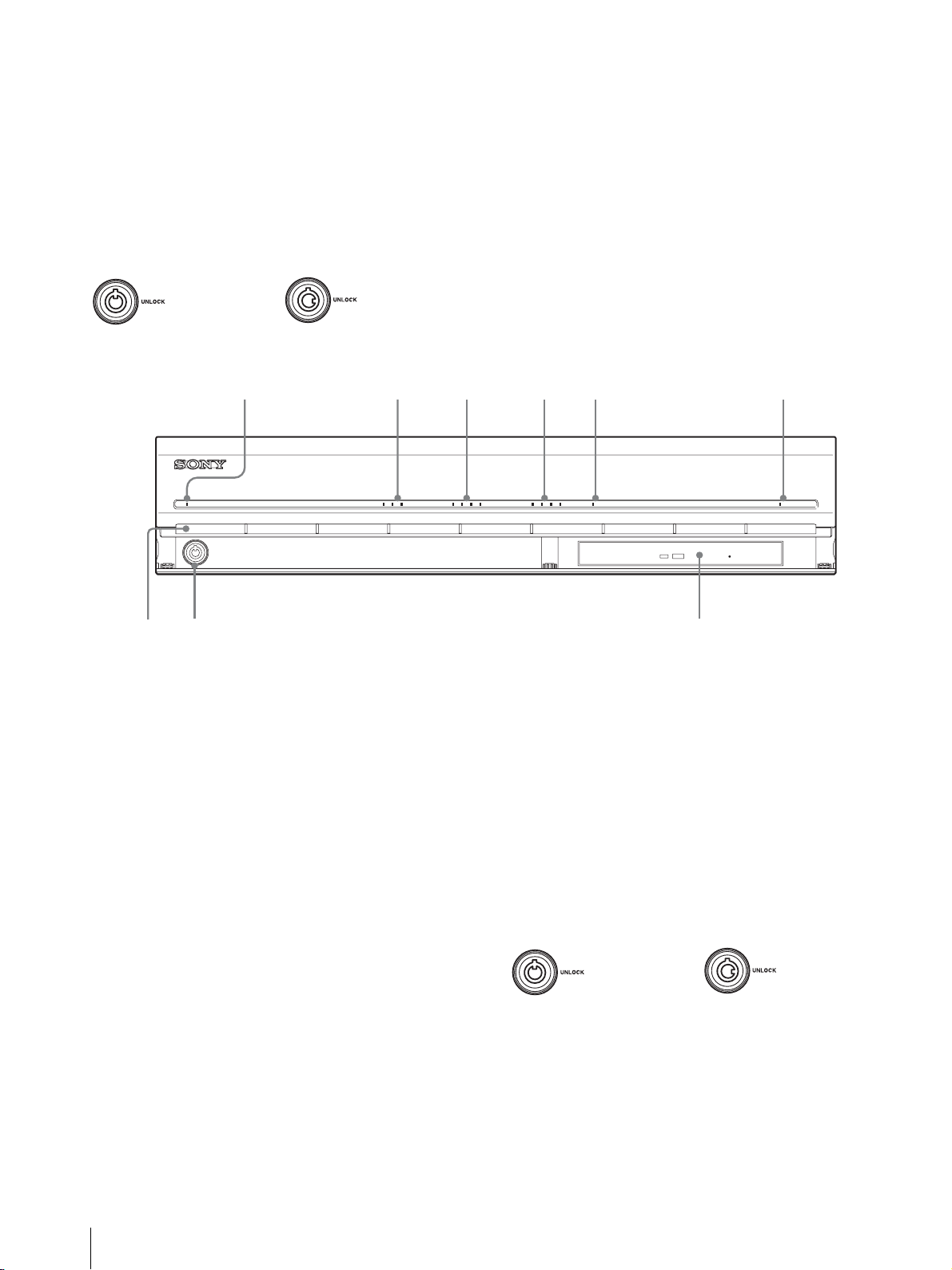
N Verrou
789
Utilisez ce verrou avec la clé du panneau avant fournie
pour verrouiller le boîtier avant. Quand le boîtier avant
est verrouillé, vous ne pouvez plus le retirer. En outre, ne
verrouillez pas le boîtier avant quand il est retiré. Vous
pouvez différencier la position verrouillée de la position
déverrouillée en observant le verrou, comme illustré cidessous.
O Orifices de ventilation
Ces ouvertures permettent à l’air de circuler de l’avant
du NSR vers l’arrière.
N’obstruez pas les orifices de ventilation. Ne laissez pas
la poussière s’accumuler dans la grille intérieure des
orifices de ventilation ou obstruer le flux d’air. Si le flux
d’air ne peut circuler, le NSR risque de chauffer, ce qui
pourrait causer des dommages ou un incendie.
Le boîtier avant est
verrouillé.
Le boîtier avant est
déverrouillé.
l
NSR-25
123 4 5 6
POWER 1 2 3NETWORK 1 2 3 4HDD 1 2 3 4 ERRORSTATUS REC
A Diode Power
Alterne entre le vert et l’orange lors du démarrage de
l’appareil.
S’allume en vert quand le démarrage est terminé.
S’allume en orange quand il est en veille.
B Diodes Réseau
S’allume en vert quand le connecteur LAN
correspondant à l’arrière du NSR est actif.
C Diode HDD
Clignote en vert lors des accès aux disques durs internes.
S’allume en orange quand une erreur se produit avec le
disque dur.
D Diodes Etat (1 à 4)
S’allument en séquence (1, 2, 3, 4) quand le NSR
démarre. Quand une erreur se produit, la diode Etat
adéquate s’allume en même temps que la diode Error,
qui s’allume ou clignote pour indiquer le type d’erreur.
Pour en savoir plus, consultez « Diodes ÉTAT » (page 81).
E Diode Error
S’allume ou clignote quand une erreur se produit.
F Diode REC
S’allume lors de l’enregistrement d’images.
* Cette fonction n’est pas prise en charge actuellement.
G Lecteur combo
Utilisez ce graveur pour écrire les données des disques
durs du NSR sur un CD.
H Verrou
Utilisez ce verrou avec la clé du panneau avant fournie
pour verrouiller le boîtier avant. Quand le boîtier avant
est verrouillé, vous ne pouvez plus le retirer. En outre, ne
verrouillez pas le boîtier avant quand il est retiré. Vous
pouvez différencier la position verrouillée de la position
déverrouillée en observant le verrou, comme illustré cidessous.
Le boîtier avant est
verrouillé.
Le boîtier avant est
déverrouillé.
I Orifices de ventilation
Ces ouvertures permettent à l’air de circuler de l’avant
du NSR vers l’arrière.
N’obstruez pas les orifices de ventilation. Ne laissez pas
la poussière s’accumuler dans la grille intérieure des
orifices de ventilation ou obstruer le flux d’air. Si le flux
d’air ne peut circuler, le NSR risque de chauffer, ce qui
pourrait causer des dommages ou un incendie.
66
Caractéristiques et fonctions
Page 67

Arrière
9q
0q
q
q
NSR-100/50
231 654 7 8
f
A Ven ti lat eu r
Prenez soin de ne pas obstruer la grille du ventilateur. Si
la grille est obstruée, l’appareil risque de chauffer, ce qui
pourrait causer des dommages et/ou un incendie.
B Interrupteur Power
Appuyez sur l’interrupteur en position a pour mettre
l’unité sous tension.
C Connecteur de sortie vidéo
Utilisez ce connecteur pour envoyer la vidéo vers un
dispositif périphérique vidéo, comme un VCR.
Les images affichées sont identiques à celles du
connecteur moniteur 1.
D Connecteur de sortie S-vidéo
Utilisez ce connecteur pour envoyer la vidéo vers un
dispositif périphérique vidéo muni d’un connecteur Svidéo.
Les images affichées sont identiques à celles du
connecteur moniteur 1.
d
s
H Connecteur d’entrée audio*
Utilisez ce connecteur pour entrer de l’audio en
provenance d’un dispositif périphérique audio, comme
un microphone.
I Connecteur SCSI*
Utilisez ce connecteur pour connecter un dispositif
périphérique SCSI.
J Connecteur USB
Utilisez ce connecteur pour connecter un clavier USB,
une souris USB, une mémoire flash USB ou la
télécommande RM-NS10 au NSR.
K Connecteurs LAN (1 à 3)
Utilisez ces connecteurs pour connecter des câbles
réseau 10 Base-T, 100 Base-TX ou 1000 Base-T au
NSR.
LAN1 : Caméras réseau
LAN2 : Clients distants
LAN3 : Dispositifs de stockage externe**
a
E Connecteur Série (RS-232C)
Utilisez ce connecteur pour connecter la ligne de
contrôle d’alimentation sans interruption (UPS).
F Connecteur d’entrée capteur
Utilisez ce connecteur pour connecter les lignes d’entrée
du capteur.
Pour les détails de connexion et les schémas de câblage
des entrées de capteur, consultez « Port d’E/S »
(page 86).
G Connecteur de sortie alarme
Utilisez ce connecteur pour connecter les lignes de sortie
d’alarme.
Pour les détails de connexion et les schémas de câblage
des sorties d’alarme, consultez « Port d’E/S » (page 86).
L Connecteur moniteur (1 et 2)
Utilisez ce connecteur pour connecter un moniteur.
M Connecteurs de sortie audio (L et R)
Utilisez ces connecteurs pour envoyer l’audio vers un
dispositif périphérique audio.
N Connecteur d’alimentation
Utilisez ce connecteur pour connecter le cordon
d’alimentation.
* Cette fonction n’est pas prise en charge actuellement.
** Selon la version logicielle, certains dispositifs de stockage
externe peuvent ne pas être pris en charge. Pour plus de
détails, consultez votre distributeur.
Caractéristiques et fonctions
67
Page 68

NSR-25
7890q
21 43 5 6
a
A Ventilateur
Prenez soin de ne pas obstruer la grille du ventilateur. Si
la grille est obstruée, l’appareil risque de chauffer, ce qui
pourrait causer des dommages et/ou un incendie.
B Interrupteur Power
Appuyez sur l’interrupteur en position a pour mettre
l’unité sous tension.
C Connecteur Série (RS-232C)
Utilisez ce connecteur pour connecter la ligne de
contrôle d’alimentation sans interruption (UPS).
D Connecteur d’entrée capteur
Utilisez ce connecteur pour connecter les lignes d’entrée
du capteur.
Pour les détails de connexion et les schémas de câblage
des entrées de capteur, consultez « Port d’E/S »
(page 86).
E Connecteur de sortie alarme
Utilisez ce connecteur pour connecter les lignes de sortie
d’alarme.
Pour les détails de connexion et les schémas de câblage
des sorties d’alarme, consultez « Port d’E/S » (page 86).
I Connecteur moniteur (1 et 2)
Utilisez ce connecteur pour connecter un moniteur.
J Connecteurs de sortie audio (L et R)
Utilisez ces connecteurs pour envoyer l’audio vers un
dispositif périphérique audio.
K Connecteur d’alimentation
Utilisez ce connecteur pour connecter le cordon
d’alimentation.
* Cette fonction n’est pas prise en charge actuellement.
F Connecteur d’entrée audio*
Utilisez ce connecteur pour entrer de l’audio en
provenance d’un dispositif périphérique audio, comme
un microphone.
G Connecteur USB
Utilisez ce connecteur pour connecter un clavier USB,
une souris USB, une mémoire flash USB ou la
télécommande RM-NS10 au NSR.
H Connecteurs LAN
Utilisez ces connecteurs pour connecter des câbles
réseau 10 Base-T, 100 Base-TX ou 1000 Base-T au
NSR.
68
Caractéristiques et fonctions
Page 69

Quand le boîtier avant est ouvert
Installation
Lorsque vous êtes sûr que l’emplacement choisi pour
installer le NSR fournit un espace approprié et la force
pour supporter l’enregistreur, connectez le cordon
d’alimentation CA.
Le NSR-100 pèse environ 14 kg (31,1 lb.), le NSR-50
pèse environ 12 kg (26,7 lb.), et le NSR-25 pèse environ
11 kg (24,2 lb.). Le NSR a les dimensions suivantes.
87 mm
(3,4
pouces)
430 mm
(16,9
pouces)
Dessus
417 mm
(16,4
pouces)
494 mm (19,4 pouces)
117 mm
(4,6 pouces)
123 mm
(4,8 pouces)
106 mm
(4,2 pouces)
102 mm
(4,0 pouces)
377 mm (14,8 pouces)
479 mm (18,9 pouces)
377 mm (14,8 pouces)
Vous pouvez installer le NSR dans un montage en
châssis ou sur une surface plane. Si vous prévoyez de
l’installer sur une surface plane, vous devez fixer les
pieds en caoutchouc fournis au fond du châssis.
Dessus
430 mm (16,9 pouces)
Quand le boîtier avant est fermé
417 mm (16,4 pouces
40 mm (1,6 pouces)
377 mm (14,8 pouces)
417 mm (16,4 pouces)
Installation sans châssis
Fixez les pieds en caoutchouc fournis sur l’enregistreur.
Placez l’enregistreur verticalement pour que la surface
du fond soit visible. Collez alors les surfaces adhésives
des pieds en caoutchouc sur le fond de l’enregistreur
comme illustré ci-dessous.
Retirez le
film
Pieds en
caoutchouc
Fond de l’appareil
Installation
69
Page 70

Installation de montage du châssis
Remarque
Installez le NSR sur un châssis à l’aide du kit de
montage en châssis en option (vendu séparément).
Avertissement
• N’utilisez pas un kit de montage en châssis autre que
le kit de montage en option (vendu séparément) pour
le NSR, cela pourrait s’avérer dangereux et provoquer
un incendie, un choc ou une blessure.
• Si vous montez le NSR sur un châssis, assurez-vous de
ne poser aucun objet lourd dessus.
• Avant de monter le NSR sur un châssis, nous
recommandons que vous marquiez sa position prévue
sur le châssis avec un feutre. Monter le NSR sur un
châssis autrement qu’horizontalement pourrait
provoquer des dysfonctionnements.
• Pour commander un kit de montage en châssis,
contactez votre détaillant.
Sortir les rails intérieurs
Sortez les rails intérieurs des assemblages de rails.
1
Sortez le rail intérieur de l’un des assemblages de
rails aussi loin que vous le pouvez.
Arrière de l’assemblage
de rails
Le rail intérieur sera installé sur le NSR, tandis que
l’assemblage de rails sera installé sur le châssis.
Préparation du NSR
Utilisez les attaches et les vis fournies pour installer le
rail intérieur sur le NSR.
1
Utilisez les vis à tête plate fournies pour attacher
l’anneau de montage sur l’avant du panneau latéral.
Anneau de
montage
Vis à tête
plate
2
Utilisez le reste des vis à tête ronde fournies pour
installer les rails sur le NSR, comme illustré cidessous.
Rail intérieur
Assemblage
de rails
2
Retournez l’assemblage de rails. Après avoir
repoussé l’onglet vert pour libérer le verrou, tirez le
rail intérieur jusqu’au bout.
Onglet vert
3
Répétez la même procédure avec l’autre
assemblage de rails pour sortir son rail intérieur.
Onglet vert
Attention
Utiliser d’autres vis que celles fournies peut
endommager l’appareil. Veillez à utiliser les vis
fournies pour installer les rails.
Vis à tête
ronde
Préparation du châssis
Installez les rails sur le châssis.
1
Déterminez l’endroit où vous voulez installer les
rails sur le châssis.
Nous recommandons le marquage de cette position
avec un marqueur ou un feutre.
Rail
70
Installation
Page 71

Attention
Des rails installés à différentes hauteurs pourrait
provoquer des dysfonctionnements du NSR.
2
Installez les rails sur le châssis.
(1) Ajustez la longueur des rails pour qu’elle
corresponde à la longueur de votre châssis.
(2) Utilisez les vis à tête bombée et les rondelles
fournies pour fixer les deux extrémités des rails
au châssis.
2
Soulevez le NSR, introduisez le rail intérieur dans
les rainures du rail coulissant (blanc), puis faites
glisser l’assemblage jusqu’à ce qu’il s’arrête.
Rail
intérieur
3
Tout en poussant l’onglet vert vers l’intérieur pour
désactiver le verrou, faites glisser le NSR aussi loin
qu’il peut aller.
Onglet vert
Rondelles
Montage du NSR sur le châssis
Insérez le NSR dans le châssis, puis fixez-le.
Attention
Il faut au moins deux personnes pour manipuler
l’appareil et ainsi éviter les blessures.
1
Sortez les rails coulissants des assemblages de rails.
Vis à
tête
bombée
Installation
71
Page 72

4
Utilisez les vis à tête bombée et les rondelles
fournies pour fixer le NSR au châssis.
Vis à tête
ronde
Remarque
Lors de l’utilisation du NSR-25, seuls les deux
connecteurs USB à l’arrière de l’appareil sont
disponibles. Le raccordement à un clavier et une
souris rend la première configuration plus facile.
Connexion du cordon
d’alimentation
1
Connectez le cordon d’alimentation au connecteur
d’alimentation à l’arrière du NSR, puis connectez
l’autre extrémité à la prise murale.
* Le reste du manuel utilise des illustrations et des écrans
d’affichage du NSR-100/50.
Connexion d’un moniteur
Connectez le moniteur au connecteur moniteur1 à
l’arrière de l’enregistreur.
Connexion du clavier, de la souris
et de la télécommande (RM-NS10)
1
Connectez le clavier au connecteur USB à l’arrière
(ou à l’avant) de l’enregistreur.
2
Connectez la souris ou la télécommande (RMNS10) au connecteur USB.
1
2
Remontez le clip de sécurité du cordon
d’alimentation et enclenchez-le pour l’empêcher de
se déconnecter.
Remarque
Avant de procéder à l’installation, lisez
attentivement la section intitulée « Importantes
informations concernant la sécurité » (page 60). Si
vous utilisez plusieurs NSR, assurez-vous que vous
disposez d’une puissance suffisante.
Vers la prise
murale
72
Installation
Page 73

Connexion du câble réseau
Connectez le câble réseau.
Reliez l’extrémité du câble réseau à l’un des connecteurs
LAN à l’arrière du NSR. Reliez l’autre extrémité au
concentrateur de commutation.
Remarque
Connexion d’autres dispositifs
Utilisation d’une carte CompactFlash
(NSR-100/50 uniquement)
Insérez votre carte CompactFlash dans la direction
illustrée. Assurez-vous d’insérer votre carte avec la face
étiquetée vers le haut et dans la direction de la flèche.
POWER 1 23LAN 1 2 34HDD 1 2 3 4 ERRORSTATUS REC
L’adresse IP par défaut pour le port LAN 1 apparaît
comme suit :
• Connecteur LAN 1 : 192.168.0.1
• Connecteur LAN 2 : 192.168.1.1 (NSR-100/50
uniquement)
• Connecteur LAN 3 : 192.168.2.1 (NSR-100/50
uniquement)
Si vous voulez modifier l’adresse IP par défaut,
consultez le « Guide de l’utilisateur » (PDF) situé sur le
« CD du manuel, des outils & des codes source du Série
NSR » fourni.
Connexion d’une caméra réseau
Utilisez un câble réseau pour connecter le connecteur
LAN 1 à un concentrateur réseau, puis connectez la
caméra réseau souhaitée au concentrateur avec un autre
câble réseau.
Concentrateur de
commutation
Caméra réseau
Pour éjecter une carte CompactFlash, appuyez sur le
bouton Eject à gauche de l’emplacement de carte.
Attention
Soyez prudent lorsque vous éjectez une carte
CompactFlash, car elle peut être expulsée du pilote
énergiquement.
Connexion d’une source d’alimentation
sans interruption
1
Connectez la source d’alimentation sans
interruption à la prise murale.
2
Connectez le NSR au SAI avec le cordon
d’alimentation fourni.
3
Connectez le NSR au SAI avec le câble série dédié
au connecteur série à l’arrière du NSR.
Connexion d’un client distant
Si un client distant est nécessaire, le logiciel Controller
RealShot Manager fourni peut être utilisé.
RealShot Manager Controller fonctionne sur les
ordinateurs munis de Windows. Pour en savoir plus sur
les conditions requises du système, reportez-vous aux
notes de mise à jour qui accompagnent l’archive
d’installation du contrôleur RealShot Manager. Veillez
également à utiliser le RealShot Manager fourni avec le
NSR.
1
Utilisez un câble réseau pour brancher le
connecteur LAN à un concentrateur réseau.
Lorsque vous utilisez le NSR-100/50, utilisez le
connecteur LAN 2 sur l’appareil.
Installation
73
Page 74

2
Connectez le câble réseau à un ordinateur quand le
logiciel du contrôleur RealShot Manager est
installé.
Concentrateur de
commutation
(Pour le NSR-100/50
uniquement)
Logiciel du contrôleur
RealShot Manager
PC Windows
Mise sous et hors
tension
Mise sous tension
Appuyez sur l’interrupteur d’alimentation.
Remarques
• Pour les détails sur l’installation et autres sujets
relatifs au logiciel RealShot Manager Controller,
consultez le CD-ROM fourni du manuel, des outils et
des codes sources du série NSR.
• Lorsque vous utilisez RealShot Manager comme
contrôleur distant pour le NSR, sélectionner
[Controller] durant l’installation de RealShot
Manager.
• Le port de connection par défaut pour la fonction du
serveur RealShot Manager sur l’unité NSR est
« 8081 ». Le port de connection peut être modifié
depuis le NSR.
• Lorsque vous utilisez le NSR-100/50, utilisez le
connecteur LAN 2 à l’arrière du NSR même pour le
connecter à la zone d’utilisateur d’un réseau.
Lorsque le démarrage est terminé, la diode Power
s’allume en vert.
Remarques
• Immédiatement (environ 2 secondes) après la mise
sous tension, le ventilateur de refroidissement émet un
bruit fort. C’est normal et cela ne veut pas dire que
l’appareil doit être réparé.
• Lorsque le NSR démarre pour la première fois,
l’assistant de configuration se lance automatiquement.
Pour en savoir plus sur la procédure de configuration,
consultez le « Guide de l’utilisateur » (PDF) dans le
« CD du manuel, des outils et des codes source du
Série NSR ».
• Si le NSR a été arrêté incorrectement lors de
l’utilisation précédente, le démarrage peut prendre
plus de temps que d’habitude.
Mise hors tension
1
Connectez-vous au NSR, et cliquez sur [Système]
en haut de la fenêtre.
L’écran de menu de système apparaît.
Un message de confirmation s’affiche.
74
Mise sous et hors tension
2
Cliquez sur [Arrêterle sytème].
3
Cliquez sur [OK] pour confirmer.
Le système s’arrête, puis l’appareil s’arrête.
Page 75
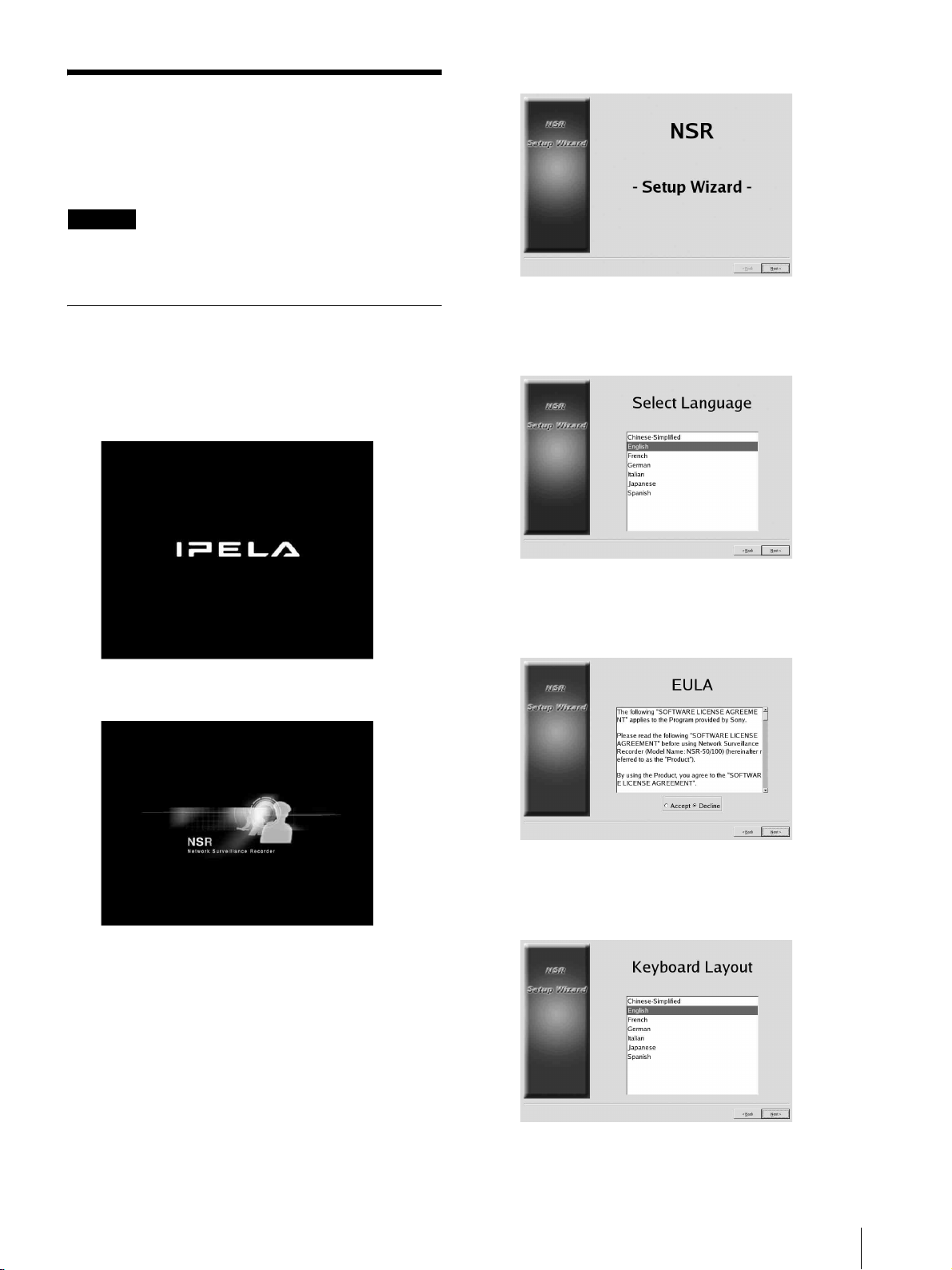
Opérations de base
(configuration initiale de
base)
Attention
Certains éléments qui apparaissent à l’écran en anglais
sont écrit en français dans ce manuel.
Configuration de base
1
Connectez le clavier USB et la souris USB à l’unité
et mettez sous tension.
L’écran suivant apparaît, et une barre de
progression de démarrage de matériel s’affiche.
2
Cliquez sur [Suivant].
L’écran [Select Language] apparaît.
3
Choisissez la langue d’affichage désirée dans la
liste, puis cliquez sur [Suivant].
Puis l’écran suivant apparaît, et une barre de
progression de démarrage de logiciel s’affiche.
L’unité démarre et l’écran de réglages du système
(Assistant de configuration) apparaît.
L’écran [EULA] apparaît.
4
Lisez la licence d’utilisateur, cliquez sur
[Accepter], puis sur [Suivant].
L’écran [Keyboard layout] apparaît.
5
Sélectionnez dans la liste le type de clavier USB
connecté à l’unité, puis cliquez sur [Suivant].
L’écran [Time Zone] apparaît.
Opérations de base (configuration initiale de base)
75
Page 76

6
Choisissez le fuseau horaire désiré dans la liste,
puis cliquez sur [Suivant].
* Il n’y a pas d’option pour activer ou désactiver
l’heure d’été. Si vous sélectionnez un fuseau dans
lequel l’heure est ajustée pour l’été, l’ajustement
sera automatique.
L’écran [Date and Time] apparaît.
7
Vérifier la date et l’heure, et configurez-les
correctement si nécessaire, puis cliquez sur
[Suivant].
Secondary DNS
Saisissez l’adresse IP du DNS secondaire.
S’il n’y a aucun DNS secondaire ou s’il n’est
pas nécessaire, ne saisissez pas d’adresse IP.
Default Gateway
Saisissez l’adresse IP de la passerelle par défaut.
Si le réseau local seul est utilisé ou si la
connexion à d’autres réseaux n’est pas
nécessaire, ne saisissez pas d’adresse IP.
L’écran [Network Device #1] apparaît.
(2) Configurez les paramètres [Network Device]
pour chacun des ports LAN.
Lorsque vous utilisez le NSR-100/50,
configurez les paramètres pour chacun des trois
ports LAN (LAN1, LAN2, et LAN 3).
Lorsque vous utilisez le NSR-25, configurez les
paramètres pour chaque port LAN (LAN1).
Configurez les paramètres selon
l’environnement d’utilisation, et cliquez sur
[Suivant] pour chacun des écrans de paramètres.
Remarque
L’écran [General Network Setting] apparaît.
8
Procédez aux étapes suivantes pour configurer les
réglages de réseau.
(1) Saisissez une adresse IP pour chaque serveur sur
l’écran [General Network Setting], puis cliquez
sur [Suivant].
Primary DNS
Saisissez l’adresse IP du DNS primaire (serveur
de noms de domaine).
Si il n’y a aucun DNS primaire ou s’il n’est pas
nécessaire, ne saisissez pas d’adresse IP.
Lorsque vous utilisez le NSR-100/50, connectez
les dispositifs suivants à chaque port LAN.
LAN1: Caméras réseau
LAN2: Clients distants
LAN3: Dispositifs de stockage externe (non
pris en charge selon la version logicielle. Pour
plus de détails, consultez votre distributeur.)
Lors de l’utilisation d’un serveur DHCP
pour la configuration automatique de
paramètres d’adresses
Sélectionnez [DHCP].
Lors de la configuration manuelle
d’adresses
(1) Sélectionnez [Static].
(2) Entrez les informations suivantes.
IP Address
Saisissez l’adresse IP souhaitée.
76
Opérations de base (configuration initiale de base)
Page 77

Attention
• Avant d’entrer l’adresse IP, assurez-vous
qu’elle n’est pas déjà utilisée sur le
réseau. La saisie d’une adresse IP déjà
utilisée peut causer un fonctionnement
erratique de l’appareil, sans qu’aucun
message d’erreur ne l’indique.
• En raison des règles d’attribution
d’adresses IP, il n’est pas permis de
définir une adresse invalide comme celles
ci-dessous.
Exemple : 224.0.0.0 à 255.255.255.255
0.0.0.0
127.0.0.1, etc.
Netmask
Saisissez l’adresse de masque de sousréseau.
Remarque
Les réglages par défaut pour les dispositifs
de réseau sont les suivants.
IP Address : 192.168.[0/1/2]*.1
Netmask : 255.255.255.0
* Les réglages pour chacun des dispositifs
de réseau #1, #2 et #3 (Dispositif du réseau
#1 pour le NSR-25 uniquement).
• La plupart des moniteurs fonctionnent avec
[Generic Monitor], mais vous pouvez
sélectionner [Others] selon vos besoins.
Attention
Quand vous configurez les paramètres du second
moniteur, celui-ci doit être connecté au moment où
le NSR redémarre.
Lorsque vous utilisez le NSR-100/50, l’écran
[Video Setting] apparaît. Procédez à l’étape 10.
Lorsque vous utilisez le NSR-25, l’écran [Host
Name] apparaît. Procédez à l’étape 11.
10
Sélectionnez le format vidéo qui convient à votre
région, [NTSC] ou [PAL], puis cliquez sur
[Suivant].
* Cet écran n’apparaît que lorsque vous utilisez le
NSR-100/50.
Le [Monitor Model] apparaît.
9
Procédez aux réglages de taille d’écran selon
chaque port de moniteur, puis cliquez sur [Suivant].
Quand deux moniteurs sont connectés, un clic sur
[Dual Head] affiche l’écran de configuration du
second moniteur.
Sélectionnez le type de moniteur et la résolution
(pixels) qui conviennent à votre moniteur.
Remarques
• Les réglages par défaut pour les moniteurs sont
comme suit.
Ecran générique LCD ; Panneau LCD
1600×1200 : 31,5-90 ; 60
Résolution 1024×768
L’écran [Host Name] apparaît.
11
Effectuez les réglages de chaque élément, puis
cliquez sur [Suivant].
Host Name
Saisissez le nom d’hôte.
Remarque
Utilisez uniquement des caractères
alphanumériques, traits de soulignement (_) et
traits d’union (-).
Domain Name
Saisissez le nom de domaine du réseau selon votre
réseau.
Exemple : xxx.sony.co.jp
Opérations de base (configuration initiale de base)
77
Page 78

Si vous n’enregistrez pas le NSR au DNS, il n’est
pas nécessaire de changer les réglages par défaut.
L’écran [Summary] apparaît.
12
Vérifiez les réglages puis cliquez sur [Suivant].
L’écran [Warning] apparaît.
13
Cliquez sur [Terminer].
Le panneau de caméra apparaît dans la fenêtre de
configuration.
2
Cliquez sur [Configuration IP des caméras].
Si les adresses IP des caméras ont déjà été
configurées, appuyez sur [Register All] et procédez
à l’étape 5.
L’écran Configuration IP des caméras apparaît.
3
Effectuez les réglages suivants.
Le NSR redémarre automatiquement.
Configuration d’adresse IP de
caméra et déclaration sur le NSR.
Après le redémarrage, l’écran de connexion apparaît.
Ensuite, configurez les adresses IP pour les caméras et
déclarez-les sur le NSR.
1
Saisissez votre nom et mot de passe utilisateur et
cliquez sur [Ouverture de session].
Nom d’utilisateur par défaut : admin
Mot de passe par défaut : admin
Dans la fenêtre Configuration IP des caméras, vous
pouvez rechercher les caméras sur le même réseau
par adresse MAC et configurer leur adresse IP en
une seule opération.
(1) Sélectionnez le réseau à rechercher dans le
champ « 1. Sélectionner la carte réseau pour la
configuration IP ».
D’habitude, Réseau 1 est sélectionné comme
réseau de caméras, et une liste de caméras
détectées apparaît dans « Liste des caméras
détectées ». Les cases de toutes les caméras
détectées sont cochées.
(2) Saisissez l’information suivante dans le champ
« 2. Paramètres Réseau des Caméras ».
• Le nom d’utilisateur et le mot de passe de la
caméra dont vous configurez les paramètres.
• La gamme d’adresses IP sur le même réseau
(défaut : 0 à 254) pour lequel une distribution
automatique est à effectuer.
• Le numéro de port http (défaut : 80) pour la
communication avec les caméras.
* S’il y a une gamme fixe d’adresses IP qui
peuvent être distribuées aux caméras, assurezvous de spécifier la gamme correcte.
78
Opérations de base (configuration initiale de base)
Page 79

(3) Cliquez sur [Appliquer].
L’information saisie est reflétée dans « Liste de
caméras détectées ».
Les adresses IP sont distribuées dans la gamme
spécifiée. Puisque la liste ne s’allonge pas pour
compenser un manque éventuel d’adresses IP,
assurez-vous que la liste est correctement
configurée en modifiant les adresses de la liste
directement selon vos besoins.
A cette étape, les réglages n’ont pas encore été
appliqués aux caméras.
(4) Cliquez sur [Appliquer].
Ceci configure les paramètres de caméras selon
l’information développée dans la liste.
Les réglages prennent quelques instants.
4
Quand les réglages de chaque caméra sont
terminés, cliquez sur [Register All].
Le panneau de déclaration simultanée apparaît.
5
Effectuez les réglages suivants.
6
Quand la déclaration est complète, cliquez sur
[Fermer].
La fenêtre de configuration revient au panneau de
caméra. Les caméras déclarées sont placées dans la
liste.
7
Si nécessaire, configurez les paramètres individuels
pour chaque caméra.
Pour les détails sur les paramètres, consultez le
guide d’utilisateur fourni.
8
Quand vous avez vérifié les paramètres de chaque
caméra, cliquez sur [Surveillance].
La fenêtre « Surveillance » apparaît.
En cliquant sur [Configuration], vous pouvez
basculer vers l’écran « Configuration » et modifier
les paramètres.
Dans le panneau de déclaration simultanée, une
liste de caméras non déclarées sur le NSR
apparaît avec leurs cases cochées.
(1) Vérifiez les numéros de caméras sélectionnées
pour la déclaration dans la colonne « Numéros
des caméras à déclarer », et confirmez le nom
d’utilisateur et le mot de passe pour chaque
caméra.
Remarque
Le nom d’utilisateur et le mot de passe pour les
caméras ne sont pas réglés par défaut. Vous
pouvez régler le nom de l’utilisateur et le mot de
passe pour toutes les caméras sélectionnées à la
fois en appuyant sur « Déclarer les caméras
sélectionnées sur le NSR ».
(2) Cliquez sur [Déclarer].
Les caméras sélectionnées sont déclarées sur le
NSR.
* En cliquant sur [Configuration IP des
caméras], vous pouvez aussi revenir au
panneau de configuration IP précédent.
* Pour savoir comment utiliser les écrans
« Surveillance » et « Configuration », consultez
le guide de l’utilisateur (PDF) compris sur le CDROM du manuel, des outils et des codes sources
du série NSR.
Opérations de base (configuration initiale de base)
79
Page 80

Reconstruction d’un
Boot Menu
volume de données
(Modification des types
de RAID) (NSR-100/50
uniquement)
Les constructions RAID configurables comme volumes
de données varient selon le numéro de modèle dans le
NSR-100/50.
* RAID n’est pas disponible pour le NSR-25.
Modèle Type
NSR-100 RAID-5 670 Go Oui Oui
RAID-1+0 450 GB Oui
RAID-0 900 GB Aucun
NSR-50 Spanning 430 GB Partiel Oui
RAID-1 210 GB Oui
Attention
• Sachez que l’ensemble des informations de
configuration et des images enregistrées est supprimé
lors de la reconstruction du volume de données.
• Si la modification de réglages est nécessaire, veillez à
modifier d’abord la construction RAID.
Capacité
approximative
Redon-
dance
Réglage
par
défaut
1.QSI DVD+/-RW SDW-0826
2. WDC WD2500JD-22HBC0-(S1)
3. WDC WD2500JD-22HBC0-(S2)
4. PQI IDE DiskOnModule-(SM)
<Enter Setup>
3
Utilisez les touches fléchées du clavier pour
sélectionner [IDE DiskOnModule], et appuyez sur
Retour.
Le démarrage depuis DiskOnModule (DOM) est
lancé.
Après le démarrage, le menu DOM apparaît.
4
Cliquez sur le troisième élément, [Clean System
Restore with Changing RAID Types].
1
Connectez le clavier USB et la souris USB au NSR,
et mettez sous tension.
L’écran suivant et une barre de progression de
démarrage de matériel apparaissent.
2
Appuyez sur F12 sur le clavier pendant l’affichage
de la barre de progression.
Exemple : Pour le NSR-50 (il y a 3 éléments de
menu pour le NSR-100)
* Le nombre de périphériques et leur nom peuvent
être différents de ceux donnés dans l’exemple
d’écran suivant.
L’écran de sélection de Type de RAID apparaît.
5
Sélectionnez le type de RAID, et cliquez sur [OK].
80
Reconstruction d’un volume de données (Modification des types de RAID) (NSR-100/50 uniquement)
Page 81

Exemple : Pour le NSR-50
Diodes ÉTAT
Quand une erreur se produit, les diodes ETAT et
ERROR s’allument ou clignotent.
1 2 3 4 ERRORSTATUS
La diode ETAT indique les erreurs suivantes.
Codes d’erreur affichés pendant le démarrage
(La diode ERROR clignote quand une erreur se
produit pendant l’initialisation).
Code
d’erreur
Diodes ÉTAT Diode
ERROR
Cause possible
L’écran de confirmation apparaît.
6
Cliquez sur [OK].
La reconstruction RAID pour la restauration du
volume de données et du système entier commence.
Ce procédé peut prendre jusqu’à 5 heures environ.
Une barre de progression apparaît pendant ce
procédé.
Quand le procédé est terminé, un écran de
notification apparaît.
Exemple : Pour un NSR-50 avec RAID 1
sélectionné
1 Clignote
1234
2 Clignote Panne du ventilateur CPU
1234
3 Clignote
1234
4 Clignote Panne du batterie CMOS
1234
5 Clignote
1234
6 Clignote
1234
7 Clignote
1234
8 Clignote
1234
9 Clignote
1234
Panne de tension
d’alimentation
Module de mémoire
défectueux
Panne du mémoire d’accès
aléatoire vidéo (RAM) ou
contrôleur
Panne du contrôleur du
disque dur
Aucun dispositif
d’amorçage trouvé
Aucun système
d’exploitation d’amorçage
trouvé
Panne d’un ou plusieurs
disques durs
7
Appuyez sur Retour après la fin du procédé et le
message « Press any key to continue ! » apparaît.
L’écran revient au menu DOM.
8
Cliquez sur [Redémarrage].
Le NSR redémarre et l’assistant de configuration
apparaît.
A Clignote
B Clignote
C Clignote
D Clignote
E Clignote
1234
1234
1234
1234
1234
F Clignote
1234
Panne de volume SE
RAID
Impossible de démarrer le
serveur X11
Impossible de démarrer
l’application
Réservé pour un usage
ultérieur
Réservé pour un usage
ultérieur
Panne de volume données
RAID
Diodes ÉTAT
81
Page 82

Codes d’erreur affichés pendant le
fonctionnement
(La diode ERROR s’allume quand une erreur se
produit pendant l’utilisation).
Code
d’erreu
r
Diodes ÉTAT Diode
1 Marche Température critique
1234
2 Marche Panne du ventilateur CPU
1234
3Marche
1234
4Marche
1234
5Marche
1234
6Marche
1234
7Marche
1234
8Marche
1234
9Marche
1234
AMarche
BMarche
CMarche
DMarche
EMarche
1234
1234
1234
1234
1234
FMarche
1234
ERROR
Cause possible
Panne d’alimentation du
ventilateur
Panne de tension
d’alimentation
Panne du ventilateur du
disque dur 1
Panne du ventilateur du
disque dur 2
Le lecteur de disque dur
est endommagé.
Réservé pour un usage
ultérieur
Réservé pour un usage
ultérieur
Réservé pour un usage
ultérieur
Réservé pour un usage
ultérieur
Echec de fonctionnement
de l’application
Réservé pour un usage
ultérieur
Panne de volume données
RAID
Opération de
resynchronisation dans le
volume de données RAID*
Divers
ACCORD DE LICENCE
L’ « ACCORD DE LICENCE DU LOGICIEL » suivant
s’applique au programme fourni par Sony.
Veuillez lire l’ « ACCORD DE LICENCE DU
LOGICIEL » avant d’utiliser l’enregistreur de
surveillance réseau (Nom du modèle : NSR-100/50/25)
(ci-après dénommé le « Produit »).
En utilisant ce Produit, vous acceptez l’ « ACCORD DE
LICENCE DU LOGICIEL ».
Soyez conscient que le logiciel utilisé dans ce Produit
inclut une partie du logiciel soumis aux conditions de
l’ACCORD DE LICENCE DU LOGICIEL suivant.
Vous pouvez vérifier qu’un tel logiciel existe sur le
média CD intégré (ci-après dénommé « Logiciel
exceptionnel »). L’ ACCORD DE LICENCE DU
LOGICIEL suivant ne s’applique pas à un tel Logiciel
exceptionnel et les conditions respectives s’appliquent à
chaque Logiciel exceptionnel séparément de cet
« ACCORD DE LICENCE DU LOGICIEL ». Le
Logiciel exceptionnel ne sera jamais interprété comme
Programme tel que défini dans l’ACCORD DE
LICENCE DU LOGICIEL suivant.
ACCORD DE LICENCE DU LOGICIEL
C’est un accord légal entre vous (ci-après dénommé l’
« Utilisateur ») et Sony Corporation (ci-après dénommé
« Sony ») qui vous concède le droit d’utiliser le
programme logiciel (ci-après dénommé le
« Programme »). L’utilisation du Programme implique
l’acceptation par l’Utilisateur de ces conditions et
l’établissement de cet accord entre l’Utilisateur et Sony.
1. Le copyright et tous les autres droits en relation avec
le Programme et les documents qui accompagnent le
Programme appartiennent à Sony ou bien à la personne
ou à l’organisation légitime à l’origine (ci-après
dénommée la « Personne légitime à l’origine »)
concédant à Sony le droit d’utiliser le Programme. Il
n’est concédé à l’Utilisateur aucun autre droit que ceux
spécifiés dans cet accord.
* Une dégradation des performances du système se produira
lorsqu’une erreur survient pendant que l’opération de
resynchronisation est en cours.
82
Divers
2. Sony concède à l’Utilisateur le droit non exclusif,
indivisible et non transférable d’utiliser le Programme
dans le but d’utiliser le Produit pour lequel le
Programme a été conçu (ci-après dénommé le « Droit
d’utilisation »).
Page 83

3. L’Utilisateur ne peut pas transférer le Droit
d’utilisation à une tierce partie, ni permettre à une tierce
partie d’utiliser le Programme, à moins que l’Utilisateur
obtienne au préalable la permission écrite de Sony.
4. L’Utilisateur ne peut pas exporter ou transporter le
Programme, ou les documents qui accompagnent le
Programme, du pays dans lequel l’Utilisateur a acheté le
Produit vers un autre pays.
5. L’Utilisateur ne peut pas mettre à jour (i), ajouter ou
modifier, ni (ii) désassembler ou décompiler le
Programme en tout ou en partie, sans le consentement
exprès de Sony.
6. LE PROGRAMME EST FOURNI « TEL QUEL »
SANS GARANTIES EXPRESSES OU IMPLICITES,
Y COMPRIS LES GARANTIES DE VALEUR
MARCHANDE ET D’ADÉQUATION À UN
OBJECTIF PARTICULIER OU DE NONDÉFECTUOSITÉ.
7. Si un quelconque litige en relation avec une infraction
au droit d’auteur, au brevet ou à d’autres droits de
propriété intangibles survenait entre l’Utilisateur et une
tierce partie en conséquence de l’utilisation du
Programme, l’Utilisateur résoudra le litige à ses propres
frais, et ne portera pas plainte contre Sony ou la
Personne légitime à l’origine.
8. Sony pourra mettre fin à la licence de l’Utilisateur à la
suite d’un avis de non-respect de n’importe lequel des
termes de cet accord. Ladite fin ne donnera droit à aucun
paiement, ni aucune compensation pour dommage. Dès
la fin de cet accord, l’Utilisateur doit immédiatement
détruire le Programme, ainsi que toutes ses copies sous
toutes ses formes.
9. Si l’Utilisateur est une entité gouvernementale,
l’utilisation, la duplication ou la diffusion du
Programme et de la documentation qui l’accompagne
par l’Utilisateur sont sujettes aux restrictions prévues
dans les sous-paragraphes (c)(1) et (c)(2) de la clause du
logiciel d’ordinateur commercial à FAR 52.227-19, et
dans le sous-paragraphe (c)(I)(ii) des droits de la clause
des données techniques et du logiciel d’ordinateur à
DOD FAR 252.227-7013 et dans n’importe quelle loi ou
réglementation fédérale, nationale ou locale comparable
et, à cette fin, le fabricant est Sony Corporation situé 17-1 Konan, Minato-ku, Tokyo, Japon.
A propos de GPL-LPGL
Ce produit comprend un logiciel compatible GPL/
LGPL. Vous pouvez obtenir le code source de ce
logiciel, ainsi que le modifier et le distribuer.
Le code source est inclus dans le « CD du manuel, des
outils & des codes sources du Série NSR » fourni.
N’envoyez pas à Sony vos questions sur le contenu du
code source.
Certains logiciels fournis avec ce produit utilisent les
bibliothèques LGPL en développement glibc et gtk2
avec une méthode appelée liaison dynamique (consultez
le « Guide de l’utilisateur » (PDF) sur le « CD du
manuel, des outils & des codes source Série NSR »).
Conformément au règlement LGPL, le code source pour
ces morceaux de logiciel n’est pas fourni. Cependant,
lorsqu’il ne s’agit que du propriétaire du logiciel, des
analyses du code objet à des fins de révisions
personnelles ou de déboguage sont autorisées.
Licence MPEG-4 Video Patent
Portfolio
CE PRODUIT EST MUNI DE LA LICENCE MPEG-4
VISUAL PATENT PORTFOLIO POUR UNE
UTILISATION PERSONNELLE ET NON
COMMERCIALE PAR UN UTILISATEUR POUR
(i) ENCODER DE LA VIDÉO EN CONFORMITÉ
AVEC LA NORME VISUELLE MPEG-4
(« VIDÉO MPEG-4 »)
ET/OU
(ii) DÉCODER DE LA VIDÉO MPEG-4 QUI A ÉTÉ
ENCODÉE PAR UN UTILISATEUR IMPLIQUÉ
DANS UNE ACTIVITÉ PERSONNELLE ET NON
COMMERCIALE ET/OU OBTENUE D’UN
FOURNISSEUR VIDÉO LICENCIÉ PAR MPEG
LA POUR FOURNIR DE LA VIDÉO MPEG-4.
AUCUNE LICENCE N’EST ACCORDÉE NI
IMPLIQUÉE POUR AUCUNE AUTRE
UTILISATION. DES INFORMATIONS
SUPPLÉMENTAIRES Y COMPRIS CONCERNANT
L’UTILISATION PROMOTIONNELLE, INTERNE
ET COMMERCIALE ET LA LICENCE PEUVENT
ÊTRE OBTENUES AUPRÈS DE MPEG LA, LLC.
VOIR
HTTP://WWW.MPEGLA.COM
Divers
83
Page 84

Guide de dépannage
Avant de contacter votre détaillant ou le support
technique de Sony, veuillez vérifier les éléments
suivants. Si le problème persiste, contactez-le.
Le NSR ne fonctionne pas.
• Vérifiez que l’interrupteur d’alimentation est en
position marche.
• Vérifiez que le câble d’alimentation est connecté
correctement.
• Assurez-vous que la prise murale est alimentée.
Testez-la en y branchant un autre dispositif.
• Vérifiez qu’il n’y a pas d’accès aux disques durs (les
diodes HDD à l’avant de l’enregistreur ne clignotent
pas), puis mettez l’appareil hors tension en maintenant
enfoncé l’interrupteur d’alimentation à l’arrière de
l’appareil pendant environ 10 secondes. Redémarrez
le NSR.
• Pendant la procédure de démarrage, le NSR vérifie le
système de fichiers. La longueur de cette vérification
varie selon la quantité de données sur le NSR (dans
certains cas extrêmes, cela peut prendre jusqu’à deux
heures). Pendant la vérification du système de fichiers,
les diodes HDD à l’avant de l’enregistreur clignotent.
• Si le NSR ne démarre pas correctement, l’écran
suivant peut s’afficher.
Exemple : (Pour le NSR-100/50 uniquement)
sélectionnez « 2. Check file System » quand l’écran
suivant apparaît.
La vérification du système de fichier peut prendre
plusieurs heures.
5 Quand la vérification est terminée, sélectionnez
« 7. Shutdown the system », puis mettez
l’enregistreur hors tension.
Sélectionnez uniquement l’option de menu « 2.
Check file System » ou « 7. Shutdown the
system », car les autres options servent à la
maintenance.
6 Redémarrez le NSR et éjectez immédiatement le
CD de récupération du Série NSR. Puis, vérifiez
que le NSR démarre correctement.
Si c’est le cas, procédez comme suit.
1 Appuyez sur [Mise en arrêt] et mettez hors tension
le NSR.
2 Si vous obtenez le message « Impossible d’accéder
au disque dur. », vérifiez si les disques durs du NSR
sont correctement connectés.
3 Redémarrez le NSR et vérifiez qu’il démarre.
4 Si le même écran que ci-dessus réapparaît, insérez
le CD de récupération du Série NSR fourni dans le
lecteur CD et DVD puis mettez hors tension le
NSR. Dans cet état, redémarrez le NSR et
Le moniteur reste sans image.
• Vérifiez si le NSR est sous tension.
• Vérifiez si le cordon d’alimentation est connecté
correctement.
• Vérifiez si le câble de moniteur est connecté
correctement. Confirmez que le moniteur est connecté
au connecteur moniteur 1.
• Si vous ne configurez pas la résolution du moniteur
correctement, le message « Hors de portée » peut
s’afficher quand la résolution du moniteur est trop
faible par rapport à la sortie moniteur. Appuyez sur
CTRL+ALT+SIGNE MOINS autant de fois que
nécessaire pour baisser la résolution de la sortie
d’images. Quand la résolution de sortie d’images
atteint la résolution du moniteur, l’image apparaît.
Reconfigurez la résolution du moniteur en
conséquence. Pour en savoir plus, consultez le
« Guide de l’utilisateur » (PDF) sur le « CD-ROM du
manuel, des outils et des codes source du Série NSR ».
Le nouveau matériel externe ne
fonctionne pas correctement.
• Assurez-vous que les câbles du nouveau dispositif
externe sont correctement connectés et que les broches
ne sont pas tordues.
84
Divers
Page 85

Un dispositif externe branché au
connecteur USB ne fonctionne pas.
• Réduisez le nombre de dispositifs externes connectés
aux ports USB.
• Consultez la documentation fournie avec le dispositif.
Le système ne peut pas lire les
informations du DVD/CD.
• Assurez-vous que vous utilisez le bon type de disque.
• Assurez-vous que le DVD/CD est correctement inséré
dans le lecteur.
• Vérifiez que le DVD/CD est propre et non rayé.
Le tiroir du DVD/CD ne peut pas être
éjecté.
• Assurez-vous que le système NSR est sous tension.
• Insérez la pointe d’un stylo ou d’un trombone dans le
trou d’éjection sur le lecteur de CD et DVD
réinscriptibles. Tirez le tiroir du lecteur, puis retirez le
disque.
La diode RÉSEAU ne s’allume pas.
• Vérifiez que les câbles et l’équipement réseau sont
connectés correctement.
Impossible d’accéder au NSR depuis un
client distant.
• Assurez-vous que le NSR fonctionne correctement
(il ne doit y avoir aucun dysfonctionnement du disque
dur, du réseau, du logiciel, etc.).
• Assurez-vous que le nom d’utilisateur, le mot de passe
et le port de connexion sont correctement réglés dans
RealShot Manager.
• Consultez la section de dépannage du guide de
l’utilisateur de RealShot Manager.
Le NSR chauffe rapidement.
• Vérifiez que les ouvertures de ventilation ne sont pas
obstruées à l’avant, sur les côtés et à l’arrière de
l’appareil et assurez-vous qu’il n’y a pas
d’accumulation de poussière.
Impossible d’accéder au disque dur.
• Vérifiez que le disque dur est correctement inséré.
• Vérifiez les diodes HDD sur le panneau avant du
système. Identifiez le lecteur de disque dur défectueux
en observant les diodes du lecteur. La diode HDD d’un
disque défectueux ne s’allume pas.
• Etant donné que la diode HDD clignote très
rapidement en cas d’accès fréquent au disque dur, elle
peut sembler éteinte dans les environnements très
lumineux.
Ne peut pas accéder à la carte
CompactFlash. (NSR-100/50 uniquement)
• Assurez-vous que la carte CompactFlash est
correctement insérée.
• Assurez-vous que la carte CompactFlash est au format
VFAT.
• Assurez-vous de ne pas retirer la carte CompactFlash
dans les 10 secondes qui suivent l’accès à la carte. Si
vous retirez la carte pendant l’accès ou le transfert aux
fichiers, le NSR peut devenir instable. Vous devez
redémarrer le système pour accéder à la carte
CompactFlash.
Divers
85
Page 86

1
Port d’E/S
Distribution de contacts du port
d’E/S
Entrée de capteur
Contact No. ENTREE CAPTEUR
1 3.3 v
2IN_8 –
3IN_8 +
4IN_7 –
5IN_7 +
6IN_6 –
7IN_6 +
8IN_5 –
9IN_5 +
10 IN_4 –
11 IN_4 +
12 IN_3 –
13 IN_3 +
14 IN_2 –
15 IN_2 +
16 IN_1 –
17 IN_1 +
18 GND
Sortie d’alarme
Contact No. Sortie d’alarme
1GND
2OUT_8 –
3OUT_8 +
4OUT_7 –
5OUT_7 +
6OUT_6 –
7OUT_6 +
8OUT_5 –
9OUT_5 +
10 OUT_4 –
11 OUT_4 +
12 OUT_3 –
13 OUT_3 +
14 OUT_2 –
15 OUT_2 +
16 OUT_1 –
17 OUT_1 +
18 3.3 v
Utilisation du réceptacle d’E/S
Insérez un petit tournevis plat dans la fente supérieure ou
inférieure de l’emplacement où vous voulez placer un
câble (AWG No. 28 à 18). Tenez le tournevis enfoncé et
insérez le câble, puis relâchez le tournevis.
Attention
Ne forcez pas sur le tournevis lorsque vous l’insérez
dans la fente. Sinon vous pourriez endommager
l’appareil.
2
3
Répétez ce procédé pour connecter tous les câbles
nécessaires.
Schéma de câblage 1 pour contact
d’entrée
Intérieur de cet appareil Extérieur
contact 3, 5, 7, 9, 11, 13, 15, 17
(ENTREE CAPTEUR+)
Dispositif
2.35 kΩ
contact 2, 4, 6, 8, 10, 12, 14, 16
(ENTREE CAPTEUR-)
capteur
Sortie :
3,3 à 24 V
CC
Schéma de câblage 2 pour contact
d’entrée
Intérieur de cet appareil Extérieur
1 contact (VDD) (200 mA max)
contact 3, 5, 7, 9, 11,
13, 15, 17
(ENTREE CAPTEUR+)
2.35 kΩ
contact 2, 4, 6, 8, 10,
12, 14, 16
(ENTREE CAPTEUR-)
contact 18 (GND)
GND
Câble
Interrupteur
mécanique
ou
Sortie collecteur
ouvert
86
Port d’E/S
Page 87

Remarque
Quand vous utilisez le schéma de câblage 2, le NSR
n’est pas isolé électriquement. Veillez donc à créer des
circuits externes qui ne produiront pas de bruit, de
surtension ou de surintensité.
Schéma de câblage pour sortie
d’alarme
Intérieur de cet appareil Extérieur
contact 3, 5, 7, 9,
11, 13, 15, 17
(ENTREE
ALARME+)
Relais
magnétique 24 V
CA/24V CC, 1A ou
moins
contact 2, 4, 6, 8,
10, 12, 14, 16
(ENTREE
ALARME-)
5 V
Exemple de circuit
GND
Por t d’ E/S
87
Page 88

© 2006 Sony Corporation
Inhalt
Sicherheitsmaßnahmen ....................................... 89
Überblick .............................................................. 91
Hardwareanforderungen ....................................92
Lieferumfang ....................................................... 93
Eigenschaften und Funktionen .......................... 94
Vorderseite ........................................................ 94
Rückseite .......................................................... 96
Aufstellung ........................................................... 98
Installation ohne Rack ...................................... 98
Installation im Rack ......................................... 99
Anschließen des Monitors .............................. 101
Anschließen von Tastatur, Maus und
Fernbedienungseinheit (RM-NS10) ............. 101
Anschließen des Netzkabels ........................... 102
Anschließen des Netzwerkkabels ................... 102
Anschließen einer Netzwerkkamera ..............102
Andere Geräte anschließen ............................ 102
Anschließen von Remote-Clients ................... 103
Ein- und Ausschalten des Gerätes ................... 104
Einschalten des Gerätes .................................104
Gerät ausschalten ........................................... 104
Allgemeine Einrichtung zu Beginn .................. 104
Allgemeine Konfiguration .............................. 104
IP-Adresskonfiguration und Registrierung
beim NSR für die Kamera ............................ 108
Neuaufbau des Datenträgers (Ändern der
RAID-Typen) (nur beim NSR-100/50) ............ 110
STATUSANZEIGE ............................................ 112
Verschiedenes ..................................................... 113
LIZENZVEREINBARUNG .......................... 113
Hinweis bezüglich GPL/LPGL ...................... 114
MPEG-4 Video Patent Portfolio Lizenz ......... 114
Fehlersuche .................................................... 114
E/A-Anschluss .................................................... 116
Stiftzuweisung des E/A-Anschlusses ............. 116
Verwenden der E/A-Buchsen ......................... 117
Schaltplan 1 für Sensoreingabe ...................... 117
Schaltplan 2 für Sensoreingabe ...................... 117
Schaltplan für Alarmausgabe ......................... 117
Warenzeichen
• „IPELA“ und sind Warenzeichen der Sony Corporation.
• Microsoft und Windows sind in den USA und/oder anderen Ländern Warenzeichen oder eingetragene Warenzeichen der Microsoft Corporation.
• Ethernet ist ein eingetragenes Warenzeichen der Fuji Xerox Co. Ltd.
• Andere in diesem Dokument erwähnte Produkt- oder Systemnamen sind -Warenzeichen oder eingetragene Warenzeichen ihrer jeweiligen Eigentümer.
In den Textabschnitten werden die Symbole ® und ™ nicht verwendet.
Lesen Sie vor Gebrauch des Recorders dieses Handbuch.
• Die vollständige oder auszugsweise Reproduktion und Vervielfältigung
der Software und des mit dem Recorder gelieferten Handbuchs ohne Zustimmung des Rechteinhabers ist urheberrechtlich verboten. Gleiches
gilt für Vermietung und Verleih.
• Sony haftet nicht für Schäden, entgangene Gewinne oder andere Ansprüche Dritter, die sich aus der Verwendung des Recorders oder der
mitgelieferten Software- ergeben.
• Die vollständigen Garantiebedingungen des Recorders befinden sich auf
der beiliegenden Garantiekarte.
• Die im Lieferumfang enthaltene Software ist nicht für die Verwendung mit
anderen Recordern geeignet.
• Es ist nicht möglich, andere als die von Sony mitgelieferte, speziell für
den Gebrauch mit diesem Gerät vorgesehene Software im Gerät zu installieren.
• Die technischen Daten des Recorders und der mitgelieferten Software
können aus Gründen des technischen Fortschritts jederzeit ohne Ankündigung geändert werden.
• Der Recorder verwendet zum Speichern des Kennworts die Funktion
MD5, die eine hohe Sicherheit gewährleistet.
Haftungsausschluss bezüglich aufgenommener
Inhalte
Sony Corporation lehnt jegliche Haftung für Konsequenzen ab, die aus nicht
erfolgter Aufzeichung oder aus Beschädigung bzw. Löschung von Aufnahmen auf diesem Gerät gleich aus welchem Grund resultieren.- Dies umfasst
auch Schadensersatzansprüche, die sich auf das aufgezeichnete Material
beziehen sowie auf gleichzeitig einhergehende und Folgeschäden.- Sony
Corporation leistet keine Wiederherstellung, Reparatur oder Vervielfältigung
von aufgezeichneten Inhalten. Der Gebrauch des Produkts unterliegt diesen
Bedingungen.
Vor dem Lesen des Handbuchs
Lesen Sie die Ergänzung „Wichtige Sicherheitshinweise“.
88
Inhalt
Page 89

Sicherheitsmaßnahmen
Wichtige Sicherheitsinformationen
• Dieses Gerät weist folgende elektrische
Spezifikationen auf. Schließen Sie das Gerät
ausschließlich an eine Stromquelle an, die diesen
Anforderungen vollständig entspricht.
- Spannung: 100 - 127 bzw. 200 - 240 V
Wechselstrom
- Stromaufnahme: 8/4 A
- Leitungsfrequenz: 50/60 Hz
• Verwenden Sie ausschließlich das mitgelieferte
Netzkabel. Wickeln Sie das Netzkabel nicht auf und
bündeln Sie es nicht mit anderen Kabeln. Schließen
Sie nicht zu viele Geräte an eine Steckdose an. Wenn
die Stromstärke zu hoch ist, bestehen Feuergefahr und
die Gefahr anderer Unfälle.
• Vergewissern Sie sich, dass alle Netzsteckdosen und
Netzkabel ordnungsgemäß geerdet sind.
• Verwenden Sie das Gerät nicht, wenn Abdeckungen
oder das Gehäuse geöffnet oder abgenommen wurden.
Andernfalls besteht Feuergefahr und die Gefahr eines
elektrischen Schlags. Versuchen Sie nicht selbst,
Abdeckungen oder das Gehäuse zu öffnen oder
abzunehmen. Wenden Sie sich immer an Ihren
Händler, wenn das Öffnen des Geräts erforderlich ist.
Wichtige Installationsinformationen
Ort für Betrieb/Lagerung
Um die Lebensdauer des Produkts zu verlängern,
verwenden oder lagern Sie es möglichst nicht an Orten,
die folgenden Bedingungen ausgesetzt sind:
• Extremer Hitze oder Kälte (die zulässige
Betriebstemperatur liegt zwischen +5 °C bis +40 °C/
+41 °F bis +104 °F).
• Direktem Sonnenlicht über längere Zeit hinweg und
Hitze von Heizgeräten. Beachten Sie, dass die
Temperatur in einem geschlossenen Fahrzeug im
Sommer +50 °C/122 °F übersteigen kann.
• Hoher Luftfeuchtigkeit oder übermäßig viel Staub
• Starken Vibrationen
• Starken magnetischen Feldern
• Unmittelbarer Nähe zu Radio- oder Fernsehsendern,
die ein starkes magnetisches Feld erzeugen.
• Achten Sie darauf, dass sich keine Kabel oder anderen
Gegenstände in der Nähe der Ventilatoröffnung an der
Rückseite des Geräts befinden. Wenn die Öffnung
blockiert wird, kann sich im Gerät ein Hitzestau
bilden und es besteht Feuergefahr und die Gefahr von
Sachschäden.
• Wenn das Gerät in einem Gestell installiert ist, müssen
Sie ebenfalls darauf achten, dass die Ventilatoröffnung
an der Rückseite sowie die Lüftungsöffnungen an der
Vorderseite nicht durch Kabel oder andere
Gegenstände blockiert werden. Installieren Sie das
Gerät nicht in einer Umgebung, in der die oben
genannten Bedingungen nicht erfüllt sind.
Verwenden Sie das Gerät in waagrechter
Position
• Dieses Gerät ist für den Betrieb in waagrechter
Position konzipiert.
• Stellen Sie das Gerät nicht auf eine geneigte
Oberfläche und schützen Sie das Gerät vor Stößen.
• Wenn das Gerät herunterfällt oder auf andere Weise
heftigen Stößen ausgesetzt wird, kann es schwer
beschädigt werden.
• Wenn Sie das Gerät in einem Gestell installieren,
vergewissern Sie sich, dass es in waagrechter Position
bleibt. Wenn das Gerät nicht richtig waagrecht
ausgerichtet ist, kann es zu Fehlfunktionen kommen.
Außerdem empfiehlt es sich dringend, das Gestell
sicher an einer Wand o. ä. zu verankern, so dass es
nicht umkippen kann.
Wartung
• Ziehen Sie vor dem Reinigen des Geräts und anderen
Wartungsarbeiten unbedingt den Netzstecker aus der
Netzsteckdose.
• Wischen Sie zum Reinigen mit einem trockenen Tuch
vorsichtig über das Gehäuse und die Abdeckungen.
Bei hartnäckigen Verschmutzungen feuchten Sie das
Tuch mit einem milden, neutralen Reinigungsmittel
leicht an und wischen mit einem trockenen Tuch nach.
• Verwenden Sie keinen Reinigungsalkohol, keine
Lösungsmittel, kein Benzin, keine Insektizide oder
andere flüchtige Substanzen, da diese die Oberfläche
angreifen und zu Verfärbungen führen können.
• In den Lüftungsöffnungen vorn am Gerät kann sich
Staub ansammeln. Achten Sie beim Entfernen des
Staubs darauf, das Gerät keinen Erschütterungen oder
Vibrationen auszusetzen.
DE
Blockieren Sie die Lüftungsöffnungen nicht
• Die Lüftungsöffnungen an den Seiten des Geräts
dienen zum Verhindern eines Hitzestaus im Gerät.
Lassen Sie auf beiden Seiten sowie hinter und über
dem Gerät immer mindestens 10 cm Platz.
• Verwenden Sie das Gerät nicht in einem
geschlossenen Schrank, einem geschlossenen Regal o.
ä.
Transport
Verpacken Sie das Gerät im Original- oder ähnlichem
Verpackungsmaterial, um es vor Stößen zu schützen.
Sicherheitsmaßnahmen
89
Page 90

Sicherheitshinweise für Produkte mit
eingebauter Festplatte
Dieses Gerät ist mit einer eingebauten Festplatte
ausgestattet. Die Festplatte ist ein Präzisionsgerät. Wenn
sie Stößen, Vibrationen, statischer Elektrizität, hohen
Temperaturen oder hoher Luftfeuchtigkeit ausgesetzt
wird, kann es zu Datenverlusten kommen. Beachten Sie
beim Installieren und Verwenden des Geräts unbedingt
folgende Sicherheitshinweise.
Schutz vor Stößen und Vibrationen
Wenn die Festplatte Stößen und Vibrationen ausgesetzt
wird, kann sie beschädigt werden und Daten können
verloren gehen.
• Verwenden Sie zum Transport des Geräts das
angegebene Verpackungsmaterial. Beim Transport auf
einem fahrbaren Rollwagen oder ähnlichem dürfen
keine übermäßigen Vibrationen auftreten. Bei starken
Stößen und Erschütterungen kann die Festplatte
beschädigt werden.
• Stellen Sie das Gerät nie um, solange es eingeschaltet
ist. Vergewissern Sie sich auch vor dem
Herausnehmen oder Einsetzen des Geräts aus einem
bzw. in ein Gestell, dass es ausgeschaltet ist.
• Schützen Sie alle mit einer Festplatte ausgestatteten
Geräte im Gestell vor Stößen.
• Vergewissern Sie sich vor dem Herausnehmen oder
Einsetzen des Geräts aus einem bzw. in ein Gestell,
dass auch alle anderen mit einer Festplatte
ausgestatteten Geräte im Gestell ausgeschaltet sind.
• Nehmen Sie keine Abdeckungen oder äußeren Teile
vom Gerät ab.
• Wenn Sie das Gerät auf den Boden oder eine andere
Oberfläche stellen, vergewissern Sie sich, dass die
zugehörigen Unterlagen angebracht sind, und setzen
Sie das Gerät vorsichtig ab. Sind keine Unterlagen
angebracht, montieren Sie zunächst die erforderlichen
Unterlagen. Stellen Sie das Gerät nicht in die Nähe
anderer Geräte, die Vibrationen verursachen könnten.
Sicherheitshinweise hinsichtlich Temperatur
und Luftfeuchtigkeit
Verwenden und lagern Sie das Gerät nur an Orten, an
denen die angegebenen Temperatur- und
Luftfeuchtigkeitswerte nicht über- oder unterschritten
werden.
Temperatur bei Betrieb: +5 bis +40 °C (+41 °F bis
+104 °F)
Luftfeuchtigkeit bei Betrieb: 20 bis 80 % relative
Luftfeuchtigkeit (maximale Feuchtlufttemperatur
30 °C/86 °F, nicht kondensierend)
Temperatur bei Lagerung: -20 bis +60 °C (-4 °F bis
+140 °F)
Luftfeuchtigkeit bei Lagerung: 20 bis 90 % relative
Luftfeuchtigkeit (maximale Feuchtlufttemperatur
40 °C/104 °F, nicht kondensierend)
Bei defekter Festplatte
Beachten Sie bitte alle oben genannten
Sicherheitshinweise, auch wenn die Festplatte bereits
Fehlfunktionen aufweist. Damit lassen sich weitere
Schäden verhindern, bis das Problem festgestellt und
behoben werden kann.
Austauschen der Festplatte
Festplatte, Ventilator und Batterie des Geräts sind
Verschleißteile, die hin und wieder ausgetauscht werden
müssen. Bei Betrieb bei Zimmertemperatur halten diese
Teile in der Regel etwa zwei bis drei Jahre. Dies ist
jedoch nur eine allgemeine Richtlinie und bedeutet
nicht, dass die Lebensdauer dieser Teile garantiert
werden kann. Wenden Sie sich zum Austauschen von
Teilen bitte an Ihren Händler.
Warten Sie nach dem Ausschalten des Geräts
30 Sekunden lang
Nach dem Ausschalten des Geräts drehen sich die
Platten im Festplattenlaufwerk eine kurze Weile weiter
und die Köpfe befinden sich in einer instabilen Position.
In dieser Zeit ist das Gerät bei Stößen und Vibrationen
noch empfindlicher als im normalen Betrieb. Schützen
Sie das Gerät nach dem Ausschalten mindestens 30
Sekunden lang selbst vor äußerst geringen
Erschütterungen. Danach befindet sich die Festplatte
vollständig im Ruhezustand und das Gerät kann
transportiert werden.
90
Sicherheitsmaßnahmen
Page 91

Überblick
Die Geräte der NSR-Reihe sind Festplattenrecorder für
Netzwerkkameras. Mit Geräten der NSR können Sie
Bilder von Netzwerkkameras überwachen und
aufzeichnen (JPEG oder MPEG-4). Darüber hinaus
können Sie die aufgezeichneten Bilder wiedergeben und
durchsuchen, was den NSR zu einer umfassenden und
vielseitigen Überwachungslösung macht.
Kompatible Kameras fernsteuern
Sie können kompatible Kameras schwenken, neigen und
zoomen lassen.
Hohe Zuverlässigkeit
Die NSR-100/50 steht für hohe Zuverlässigkeit durch:
• NSR-100: RAID 0, 1+0 und 5
• NSR-50: Spanning* und RAID 1
Bei Verwendung mit einer RAID 1, 1+0 oder 5Anordnung kann das System selbst dann weiter
funktionieren, wenn bei einer der Festplatten eine
Störung eintritt. Weil die Systemsoftware mitsamt den
Einstellungen im internen Flash-Speicher des NSR
gespeichert ist, kann das System bei Fehlfunktionen der
Systemsoftware sofort wieder hergestellt werden. Der
NSR ist auch mit unterbrechungsfreien
Stromversorgungen (USV)** kompatibel und bildet
damit ein extrem zuverlässiges Gesamtsystem.
Kompatibel mit analogen Kameras
Mit Hilfe des optionalen Kameraservers SNT-V704
können Sie Bilder von analogen Kameras überwachen
und aufzeichnen.
Großzügig dimensionierte Festplatten
gestatten Aufzeichnungen über längere
Zeiträume.
Der
NSR
ist mit Festplatten hoher Kapazität ausgestattet.
Der NSR-100 kann bis zu ca. 920 GB
der NSR-50 bis zu ca. 460 GB
zu ca. 230 GB
1)
Daten. Wenn Sie beispielsweise mit dem
NSR-100 Bilder von 16 Kameras bei 1 fps
1)
1)
Daten aufzeichnen,
Daten und der NSR-25 bis
2)
(VGA, JPEG;
Einzelbildgröße ca. 31 KB) aufzeichnen, entspricht dies
einer Aufzeichnung von etwa einem Monat Dauer (bei 15
Stunden täglich)
1) Einschließlich der Kapazität der von der internen Software
verwalteten Datenbank.
2) fps: Frames per second, Bilder pro Sekunde.
3) Wenn als RAID-0 konfiguriert.
3)
.
Flache, platzsparende 2HE-Bauweise für 19Zoll-Rackmontage
Mit dem optionalen Rack-Montagekit (als Zubehör
erhältlich) kann der Recorder in ein 19-Zoll-Rack nach
EIA-Standard (Universalraster) eingebaut werden.
Hochauflösende VGA- und JPEG-Aufnahmen
mit bis zu 480 fps
Der NSR-100 kann mit bis zu 64 Kameras, der NSR-50
mit maximal 32 Kameras und der NSR-25 mit maximal
20 Kameras verwendet werden. Der NSR-100 zeichnet
Bilder mit einer Gesamtrate von 480 fps* (NSR-50: 240
fps, NSR-25: 120 fps) in VGA-Auflösung (640 × 480
Bildpunkte) mit guter JPEG-Bildqualität (ca. 31 KB pro
Bild) auf.
* Maximale Bildrate bei 16 angeschlossenen Kameras. Jede
Kamera filmt mit einer Bildfrequenz von ca. 30 fps. Diese
Frequenz kann sich durch Fragmentierung der internen
Festplatten verringern. Die Wertangaben folgen
Messungen, die von Sony vorgenommen wurden. Für die
Korrektheit dieser Werte wird keine Garantie übernommen,
da die Leistungsdaten unter verschiedenen
Umgebungsbedingungen variieren können.
* Spanning: Funktion, mit der mehrere Festplatten virtuell
als eine einzige zusammengefasst werden.
** Nur von Sony empfohlen.
Hinweis
• Wenn Sie den NSR-100 mit RAID 0 oder den NSR-50
mit Spanning betreiben, ist keine Datenredundanz
gegeben. Die Speicherkapazität hängt zudem von der
RAID-Ebene ab.
• RAID ist nicht für den NSR-25 verfügbar.
Andere Eigenschaften
• Auf einem Bildschirm können Sie bis zu 64
Kamerabilder (8 × 8 Bilder) darstellen.
• Der NSR eignet sich u.a. für manuelle, geplante und
alarmgesteuerte Aufzeichnungen.
• Der NSR verfügt über eine Funktion zur
Aktivitätserkennung
1)
(Video Motion Detection
(Recorder)).
• Suchläufe nach aufgezeichneten Bildern sind anhand
von Kameranamen, Datum, Alarm und weiteren
Kriterien möglich.
• Mit den dynamischen Maskierungsfunktionen
2)
des
NSR können Sie Privatsphäre-Bereiche definieren.
Dynamische Maskierungsfunktionen können auf die
Schwenk-, Neigungs- und Vergrößerungsfunktion
angewendet werden.
• Eine präzise Alarmverarbeitung wird durch die
Durchführung verschiedener Arten von Filterung
3)
mit Hilfe der von der Kamera in Form von
Objektinformations-Metadaten gesendeten
Bildverarbeitungsergebnisse ermöglicht. Weil auf
bereits aufgezeichnete Metadaten Filter angewendet
werden können, können Sie auch Bereiche von
Interesse suchen, nachdem die Aufzeichnung
abgeschlossen ist.
• Tonaufnahme und -wiedergabe
4)
sind mit
kompatiblen Kameras möglich.
Überblick
91
Page 92

1) Einige Funktionen sind abhängig von der Anzahl
angeschlossener Kameras eingeschränkt.
2) Einige Funktionen sind nur bei bestimmten
Kameramodellen verfügbar.
3) Um Bewegungserkennung sowie Objecterkennung mit
Hilfe von Metadaten durchzuführen, ist eine Kamera
erforderlich, die eine Bewegungserkennung mit Metadaten
unterstützt. Die Verwendung von Metadaten wird für bis zu
32 Kameras unterstützt.
4) Die optionalen aktiven Lautsprecher sind erforderlich.
Wichtiger
In diesem Handbuch ist lediglich die Installation und
Konfiguration des NSR beschrieben. Detaillierte
Erläuterungen zur Benutzung des Recorders entnehmen
Sie dem Benutzerhandbuch (im PDF-Format) auf der
mitgelieferten NSR-Reihe-CD mit Handbüchern,
Werkzeugen und Quellcodes.
Hardwareanforderungen
Sie benötigen zum Einsatz des Recorders die
nachfolgend aufgeführte Hardware.
• Sony-Netzwerkkameras
Ausführliche Informationen über kompatible SonyNetzwerkkameras erhalten Sie bei Ihrem Händler.
• Monitor
• USB-Tastatur
•USB-Maus
• Netzwerk-Switch
• 1000Base-T-/100Base-TX-/10Base-T-Netzwerkkabel
• CF (CompactFlash)-Karte oder USB-Speichergerät
1) Einzelheiten zu den vom NSR unterstützten Monitoren
erhalten Sie von Ihrem Fachhändler.
Die folgenden Monitore vom Typ „Allgemein“ können
ausgewählt werden.
Die Frequenz steht am Ende jeder Zeile.
- Allgemeines LCD-Display; LCD-Panel 1024 × 768;
- Allgemeines LCD-Display; LCD-Panel 1280 × 1024;
- Allgemeines LCD-Display; LCD-Panel 1600 × 1200; 60
- Allgemeines CRT-Display; Monitor 1024 × 768; 50 - 70
- Allgemeines CRT-Display; Monitor 1280 × 1024; 50 - 90
- Allgemeines CRT-Display; Monitor 1600 × 1200; 50 - 90
Die folgenden Auflösungen können festgelegt werden.
- XGA (1024 × 768)
- SXGA (1280 × 1024)
- UXGA (1600 × 1200)
2) Verwenden Sie eine über ein Kabel angeschlossene USB-
Tastatur. Die Funktion nichtstandardisierter Tasten kann
nicht garantiert werden. Über Funk oder Infrarotstrahl
angeschlossene USB-Tastaturen funktionieren unter
Umständen nicht korrekt.
3) Verwenden Sie eine über ein Kabel angeschlossene USB-
Maus. Mäuse mit drei Tasten bzw. mit Scrollrad
funktionieren unter Umständen nicht korrekt. Über Funk
oder Infrarotstrahl angeschlossene USB-Mäuse
funktionieren möglicherweise ebenfalls nicht korrekt.
4) Beim Sichern von Anwendungseinstellungen erforderlich.
- Verwenden Sie für CF eine Karte, die schon mit VFAT
- Verwenden Sie als USB-Speicher ein Gerät, das den
- CF-Karten sind nicht mit dem NSR-25 kompatibel.
1)
2)
3)
4)
40 - 70
50 -75
formatiert wurde.
allgemeinen Spezifikationen der USBMassenspeicherklasse entspricht.
92
Hardwareanforderungen
Page 93

Lieferumfang
Prüfen Sie, ob die nachfolgend aufgeführten
Gegenstände in der Packung enthalten sind:
• Überwachungsrecorder NSR-100, NSR-50 oder NSR25 (1)
• Frontblendenschlüssel (2)
• Installationshandbuch (dieses Handbuch) (1)
• Karte für den Einsatz der Fernbedienungseinheit (1)
• NSR-Reihe Wiederherstellungs-CD
• NSR-Reihe-CD mit Handbüchern, Werkzeugen und
Quellcodes
• Wichtige Sicherheitshinweise (1)
• Sicherheitswarnung (1)
• Garantieunterlagen (1)
• Gummifüße (4)
Hinweise
• Enthält diese Packung möglicherweise zusätzliche
Hardware und die dazugehörige Dokumentation.
• Bewahren Sie das Verpackungsmaterial zur späteren
Verwendung auf.
• Das Rack-Montagekit kann wahlweise eingesetzt
werden (als Zubehör erhältlich). Das RackMontagekit können Sie über Ihren Fachhändler
bestellen.
• Inhalt der NSR-Reihe-CD (Handbücher, Werkzeuge
und Quellcodes):
Handbuchordner: Benutzerhandbuch und Daten zur
Karte für die Fernbedienungseinheit (mehrsprachig)
Quellcodeordner: Quellcode für GPL/LGPLkompatible Software
Werkzeug: Remote-Client-Software (RealShot
Manager), Anwendung zur Wiedergabe von CAMDateien (Media File Player) sowie zugehörige
Benutzerhandbücher
(1)
(1)
Lieferumfang
93
Page 94

Eigenschaften und Funktionen
708q
9q
q
q
q
Vorderseite
NSR-100/50
123 4 5 6
POWER 1 2 3NETWORK 1 2 3 4HDD 1 2 3 4 ERRORSTATUS REC
a
f
g
d
s
A Betriebsanzeige
Wechselt beim Hochfahren des Geräts zwischen grün
und orange.
Leuchtet grün, wenn das Hochfahren abgeschlossen ist.
Leuchtet orange, wenn der Recorder im StandbyZustand ist.
B Netzwerkanzeige (1 bis 3)
Leuchtet grün, wenn der zugehörige Netzwerkanschluss
an der Rückseite des NSR aktiv ist.
C Festplatten-Anzeige
Blinkt grün, wenn auf die internen Festplatten
zugegriffen wird.
Leuchtet orange, wenn ein Festplattenfehler aufgetreten
ist.
D Statusanzeige (1 bis 4)
Leuchten der Reihe nach auf (1, 2, 3, 4), wenn der NSR
gestartet wird. Wenn ein Fehler auftritt, leuchtet die
entsprechende Status-LED und die Fehlerzeigt durch
Leuchten oder Blinken die Fehlerart an.
Informationen hierzu finden Sie im Abschnitt
‚,STATUSANZEIGE“ (Seite 112).
E Fehleranzeige
Leuchtet oder blinkt, wenn ein Fehler auftritt.
F Aufnahmeanzeige
Leuchtet, wenn Bilder aufgezeichnet werden.
G DVD-/CD-Brenner
Wird verwendet, um Daten von den Festplatten des NSR
auf DVD oder CD zu schreiben.
* Einzelheiten zu kompatiblen Medien siehe dem
Benutzerhandbuch (PDF) auf der im Lieferumfang des
NSR-Reihe enthaltenen CD mit Handbüchern,
Werkzeugen und Quellcodes.
H USB-Anschluss
Zum Anschließen einer USB-Tastatur, einer Maus, eines
USB-Flash-Speichers oder der Fernbedienung RMNS10 an den NSR.
I Audioeingang*
Zum Anschließen einer externen Tonquelle wie z.B.
eines Mikrofons.
J Audioausgänge (L und R)
Zur Ausgabe von Tonsignalen an ein externes
Audiogerät.
K Videoausgang
Zur Ausgabe von Videosignalen an ein externes
Videogerät wie z.B. einen Videorecorder.
Die angezeigten Bilder sind die gleichen wie jene für
den Monitoranschluss 1.
L Monitoranschluss 1
Zum Anschließen eines Monitors.
M CompactFlash-Kartenschacht
Zum Speichern von Konfigurationsdaten der Festplatten
des NSR auf eine CompactFlash-Karte.
N Schloss
Dient zusammen mit dem im Lieferumfang enthaltenen
Frontblendenschlüssel zum Sichern der Frontblende
gegen Entfernung. Wenn die Frontblende gesichert ist,
kann sie nicht abgezogen werden. Die Frontblende darf
nicht in herausgezogenem Zustand abgeschlossen
werden. Die folgende Abbildung zeigt das Schloss in
verriegelter und in freigegebener Position.
94
Eigenschaften und Funktionen
Page 95

Frontblende verriegelt Frontblende freigegeben
789
O Belüftungsöffnungen
Durch diese Öffnungen kann Luft im NSR von vorne
nach hinten strömen.
NSR-25
123 4 5 6
POWER 1 2 3NETWORK 1 2 3 4HDD 1 2 3 4 ERRORSTATUS REC
Halten Sie die Lüftungsöffnungen frei. Auf dem inneren
Gitter der Lüftungsöffnungen darf sich kein Staub
ansammeln, und der Luftstrom muss stets ungehindert
passieren können. Wird der Luftstrom behindert, kann
sich Wärme im Geräteinnern stauen und zu Schäden
oder Bränden führen.
* Diese Funktion wird gegenwärtig nicht unterstützt.
A Betriebsanzeige
Wechselt beim Hochfahren des Geräts zwischen grün
und orange.
Leuchtet grün, wenn das Hochfahren abgeschlossen ist.
Leuchtet orange, wenn der Recorder im StandbyZustand ist.
B Netzwerkanzeige
Leuchtet grün, wenn der zugehörige Netzwerkanschluss
an der Rückseite des NSR aktiv ist.
C Festplatten-Anzeige
Blinkt grün, wenn auf die internen Festplatten
zugegriffen wird.
Leuchtet orange, wenn ein Festplattenfehler aufgetreten
ist.
D Statusanzeige (1 bis 4)
Leuchten der Reihe nach auf (1, 2, 3, 4), wenn der NSR
gestartet wird. Wenn ein Fehler auftritt, leuchtet die
entsprechende Status-LED und die Fehlerzeigt durch
Leuchten oder Blinken die Fehlerart an.
Informationen hierzu finden Sie im Abschnitt
‚,STATUSANZEIGE“ (Seite 112).
E Fehleranzeige
Leuchtet oder blinkt, wenn ein Fehler auftritt.
F Aufnahmeanzeige
Leuchtet, wenn Bilder aufgezeichnet werden.
G Kombilaufwerk
Wird verwendet, um Daten von den Festplatten des NSR
auf CD zu schreiben.
H Schloss
Dient zusammen mit dem im Lieferumfang enthaltenen
Frontblendenschlüssel zum Sichern der Frontblende
gegen Entfernung. Wenn die Frontblende gesichert ist,
kann sie nicht abgezogen werden. Die Frontblende darf
nicht in herausgezogenem Zustand abgeschlossen
werden. Die folgende Abbildung zeigt das Schloss in
verriegelter und in freigegebener Position.
Frontblende verriegelt Frontblende freigegeben
I Belüftungsöffnungen
Durch diese Öffnungen kann Luft im NSR von vorne
nach hinten strömen.
Halten Sie die Lüftungsöffnungen frei. Auf dem inneren
Gitter der Lüftungsöffnungen darf sich kein Staub
ansammeln, und der Luftstrom muss stets ungehindert
passieren können. Wird der Luftstrom behindert, kann
sich Wärme im Geräteinnern stauen und zu Schäden
oder Bränden führen.
Eigenschaften und Funktionen
95
Page 96

Rückseite
9q
0q
q
q
NSR-100/50
231 654 7 8
f
A Lüfter
Das Lüftergitter darf nicht verdeckt werden. Wenn der
Luftstrom blockiert wird, kann sich Hitze im Gerät
aufstauen und zu Schäden oder Bränden führen.
B Netzschalter
Bringen Sie zum Einschalten des Geräts den
Netzschalter in Position a.
C Videoausgang
Zur Ausgabe von Videosignalen an ein externes
Videogerät wie z.B. einen Videorecorder.
Die angezeigten Bilder sind die gleichen wie jene für
den Monitoranschluss 1.
D S-Video-Ausgang
Zur Ausgabe von Videosignalen an ein externes
Videogerät, das über einen S-Video-Eingang verfügt.
Die angezeigten Bilder sind die gleichen wie jene für
den Monitoranschluss 1.
E Serielle Schnittstelle (RS-232C)
Zum Anschluss der Steuerleitung der
unterbrechungsfreien Stromversorgung (USV).
F Sensoreingang
Zum Anschließen der Sensoreingangsleitungen.
Weitere Informationen zu den Anschlüssen sowie
Schaltpläne für Sensoreingänge finden Sie unter ‚,E/AAnschluss“ (Seite 116).
G Alarmausgang
Zum Anschließen der Alarmausgangsleitungen.
Weitere Informationen zu den Anschlüssen sowie einen
Schaltplan für die Alarmausgabe finden Sie unter ‚,E/AAnschluss“ (Seite 116).
d
s
H Audioeingang*
Zum Anschließen einer externen Tonquelle wie z.B.
eines Mikrofons.
I SCSI-Schnittstelle*
Zum Anschließen eines externen SCSI-Geräts.
J USB-Anschluss
Zum Anschließen einer USB-Tastatur, einer Maus, eines
USB-Flash-Speichers oder der Fernbedienung RMNS10 an den NSR.
K Netzwerkanschlüsse (1 bis 3)
Zum Anschließen von Kabeln für 10 Base-T-, 100 BaseTX- oder 1000 Base-T-Netzwerke an den NSR.
LAN1: Netzwerkkameras
LAN2: Remote-Clients
LAN3: Externe Speichergeräte**
L Monitoranschluss (1 und 2)
Zum Anschließen eines Monitors.
M Audioausgänge (L und R)
Zur Ausgabe von Tonsignalen an ein externes
Audiogerät.
N Anschluss für Netzkabel
Zum Anschließen des Netzkabels.
* Diese Funktion wird gegenwärtig nicht unterstützt.
** Externe Speichergeräte werden abhängig von der
a
Softwareversion ggf. nicht unterstützt. Einzelheiten hierzu
erfahren Sie von Ihrem Händler.
96
Eigenschaften und Funktionen
Page 97

NSR-25
7890q
21 43 5 6
a
A Lüfter
Das Lüftergitter darf nicht verdeckt werden. Wenn der
Luftstrom blockiert wird, kann sich Hitze im Gerät
aufstauen und zu Schäden oder Bränden führen.
B Netzschalter
Bringen Sie zum Einschalten des Geräts den
Netzschalter in Position a.
C Serielle Schnittstelle (RS-232C)
Zum Anschluss der Steuerleitung der
unterbrechungsfreien Stromversorgung (USV).
D Sensoreingang
Zum Anschließen der Sensoreingangsleitungen.
Weitere Informationen zu den Anschlüssen sowie
Schaltpläne für Sensoreingänge finden Sie unter ‚,E/AAnschluss“ (Seite 116).
E Alarmausgang
Zum Anschließen der Alarmausgangsleitungen.
Weitere Informationen zu den Anschlüssen sowie einen
Schaltplan für die Alarmausgabe finden Sie unter ‚,E/AAnschluss“ (Seite 116).
F Audioeingang*
Zum Anschließen einer externen Tonquelle wie z.B.
eines Mikrofons.
I Monitoranschluss (1 und 2)
Zum Anschließen eines Monitors.
J Audioausgänge (L und R)
Zur Ausgabe von Tonsignalen an ein externes
Audiogerät.
K Anschluss für Netzkabel
Zum Anschließen des Netzkabels.
* Diese Funktion wird gegenwärtig nicht unterstützt.
G USB-Anschluss
Zum Anschließen einer USB-Tastatur, einer Maus, eines
USB-Flash-Speichers oder der Fernbedienung RMNS10 an den NSR.
H Netzwerkanschlüsse
Zum Anschließen von Kabeln für 10 Base-T-, 100 BaseTX- oder 1000 Base-T-Netzwerke an den NSR.
Eigenschaften und Funktionen
97
Page 98

Bei geöffneter Frontblende
Aufstellung
Stellen Sie sicher, dass der vorgesehene Standort für
den NSR genügend Platz bietet und ausreichend
tragfähig für das Gerätegewicht ist. Schließen Sie dann
das Netzkabel an.
Der NSR-100 wiegt ca. 14 kg (31.1 lb.), der NSR-50
wiegt ca. 12 kg (26.7 lb.), und der NSR-25 wiegt ca. 11
kg (24.2lb.). Der NSR besitzt folgende Abmessungen:
87 mm
(3,4 Zoll.)
430 mm
(16,9 Zoll.)
Oberseite
417 mm
(16,4 Zoll.)
494 mm (19,4 Zoll.)
117 mm
(4,6 Zoll.)
106 mm
(4,2 Zoll.)
102 mm
(4,0 Zoll.)
123 mm
(4,8 Zoll.)
377 mm (14,8 Zoll.)
479 mm (18,9 Zoll.)
377 mm (14,8 Zoll.)
Sie können den NSR in einem Rack montieren oder auf
einer ebenen Oberfläche aufstellen. Wenn Sie das Gerät
auf einer ebenen Oberfläche aufstellen, müssen Sie die
mitgelieferten Gummifüße an der Unterseite des
Gehäuses anbringen.
Oberseite
430 mm (16,9 Zoll.)
Bei geschlossener Frontblende
417 mm (16,4 Zoll.)
40 mm (1,6 Zoll.)
377 mm (14,8 Zoll.)
Installation ohne Rack
Bringen Sie die mitgelieferten Gummifüße am Recorder
an.
417 mm (16,4 Zoll.)
Stellen Sie den Recorder senkrecht, so dass die
Unterseite sichtbar ist. Kleben Sie dann wie
nachfolgend abgebildet die Gummifüße an die
Unterseite des Recorders.
Schutzfolie
entfernen
Gummifuß
98
Unterseite des Geräts
Aufstellung
Page 99

Installation im Rack
Bei Einbau des Geräts der NSR in ein Rack ist das
wahlweise erhältliche Rack-Montagekit (wird separat
verkauft) zu verwenden.
Warnung
3
Wiederholen Sie diesen Vorgang mit der anderen
Schienenbaugruppe.
Hinweis
Die innere Schiene wird am NSR montiert, die
Schienenbaugruppe jedoch im Rack.
• Verwenden Sie für den NSR ausschließlich das
optional erhältliche Rack-Montagekit (wird separat
verkauft). Die Verwendung von anderem Material ist
gefährlich und kann zu Bränden, elektrischen
Schlägen oder Verletzungen führen.
• Wenn Sie den NSR in einem Rack montieren, stellen
Sie keine schweren Gegenstände auf den Recorder.
• Wir empfehlen, vor der Montage des NSR in einem
Rack die Montageposition mit einem Filzschreiber zu
kennzeichnen. Wird der NSR im Rack nicht horizontal
montiert, kann dies zu Fehlfunktionen führen.
• Das Rack-Montagekit können Sie über Ihren
Fachhändler bestellen.
Herausziehen der inneren Schienen
Ziehen Sie die inneren Schienen der
Schienenbaugruppen heraus.
1
Ziehen Sie dabei aus einer Baugruppe die innere
Schiene so weit wie möglich heraus.
Rückseite der
Schienenbaugruppe
Vorbereiten des NSR
Verwenden Sie die mitgelieferten Verbinder und
Schrauben, um die innere Schiene am NSR
anzubringen.
1
Bringen Sie mit Hilfe der mitgelieferten
Flachkopfschraube die Montagewinkel an der
Vorderseite der Seitenwand an.
Montagewinkel
Flachkopfschraube
2
Verwenden Sie die restlichen Rundkopfschrauben
zum Anbringen der Schienen am NSR (siehe
Abbildung).
innere Schiene
Schienenbaugruppe
2
Drehen Sie die Schienenbaugruppe um. Ziehen Sie
an der grünen Lasche, um die Sperre zu entriegeln,
und ziehen Sie die innere Schiene ganz heraus.
grüne Lasche
Schiene
grüne
Vorsi cht
Rundkopfsc
hrauben
Verwenden Sie nur die im Lieferumfang
enthaltenen Schrauben, um Beschädigungen des
Gerätes zu vermeiden. Befestigen Sie die Schienen
mit den beiliegenden Schrauben.
Aufstellung
99
Page 100
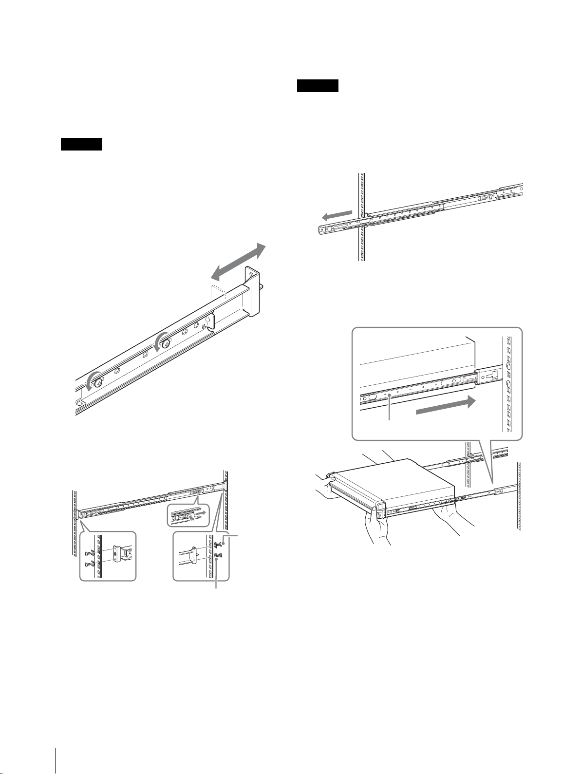
Vorbereiten des Racks
Installieren Sie die Schienen im Rack.
1
Legen Sie die Montageposition der Schienen im
Rack vorher fest.
Wir empfehlen, die Position mit einem
Filzschreiber zu kennzeichnen.
Montieren des NSR im Rack
Setzen Sie den NSR in das Rack ein, und sichern Sie ihn.
Vorsi cht
Ziehen Sie zur Vermeidung von Verletzungsgefahren die
Hilfe einer weiteren Person heran, wenn Sie das Gerät
bewegen.
Vorsi cht
Wenn die Schienen auf unterschiedlicher Höhe
montiert werden, kann dies zu Fehlfunktionen des
NSR führen.
2
Installieren Sie die Schienen im Rack.
(1) Passen Sie die Länge der Schienen der Tiefe des
Racks an.
(2) Sichern Sie mit Hilfe der mitgelieferten
Halteschrauben und Scheiben beide Enden der
Schienen im Rack.
1
Ziehen Sie die Gleitschienen der
Schienenbaugruppen heraus.
2
Heben Sie den NSR an, führen Sie die inneren
Schienen in die Gleitschienen ein (weiß), und
schieben Sie die Baugruppe dann bis zum Anschlag
ein.
innere
Schiene
100
Haltesc
hrauben
Scheiben
Aufstellung
 Loading...