

SONY SE610, SE710 Service Manual

IEEE
Std
ANSI/IEEE
114-1982
(Revision
Std
114-19691
of
IEEE
Standard
Single-Phase
Test
Procedure
Induction
for
Motors
Published
December
by
The Institute
7,
I982
of
Electrical and Electronics Engineers,
Inc
345 East 47th Street, New York, NY 10017,
USA
SH08938


IEEE
Std
114-1982
IEEE STANDARD TEST PROCEDURE FOR
IEEE
Standard Test Procedure
Single-phase Induction Motors
1.
Scope
This standard covers instructions for conducting and reporting the more generally applicable and acceptable tests to determine
the performance characteristics of singlephase motors, including nonexcited synchronous motors. It is not intended that this standard shall cover all possible tests used in production or tests of a research nature. The standard shall not be interpreted as requiring the
of
the
making of any or all
herein in any given transaction.
2.
References
111
ANSI/IEEE Std 4-1978,
Techniques for High-Voltage Testing
[2] ANSI/IEEE Std 43-1974 (R1979), IEEE
Recommended Practice for Testing Insulation
Resistance of Rotating Machinery
[3] ANSI/IEEE Std 100-1977, IEEE Standard
Dictionary of Electrical and Electronics Terms
[4] ANSI/NEMA MG 1-1978, Motors and
Generators1
[
51 IEEE Std 1-1969, IEEE General Principles
for Temperature Limits in the Rating of Electric Equipment
[6] IEEE Std 85-1973 (R1980), IEEE Test
Procedure for Airborne Sound Measurements
on Rotating Electric Machinery
[7] IEEE Std 118-1978, IEEE Standard Test
Code for Resistance Measurement
ANSI documents are available from
of
partment
1430
Broadway, New York, NY
American National Standards Institute,
tests described
IEEE Standard
the
10018.
Sales De-
for
[8] IEEE Std 119-1974, IEEE Recommended
Practice for General Principles of Temperature
Measurement as Applied to Electrical Apparatus
[9] IEEE Std 120-1955 (R1972) (ASME
PTC 19.6-1955), Master Test Code for Electrical Measurements in Power Circuits
3.
Tests
Single-phase induction motors are normally
given a routine test but may be given a complete test.
3.1
Routine Test. The routine test includes
measurement of power and current input at
no-load and at rated voltage, current input with
locked rotor at rated voltage, and a highpotential test. A suggested form for reporting
such test data is shown in Form
of this standard.
3.2
Complete Test. The complete test, includes
all of the data taken during a routine test plus
the data necessary for determining efficiency,
power factor, starting torque, pull-up torque,
breakdown torque, rated-load slip, and ratedload temperature rise. A suggested test form
for reporting data is shown in Form 2. Additional tests to determine locked-rotor temperature rise, speed-torque characteristics, shaft
current, noise, and vibration may also be con-
ducted.
3.3
Schedule
be obtained by any of the four following
methods:
Method A
Method
Method C
Method D
of
Tests. Input-output data may
-
brake
B
-
dynamometer
-
rope (or cord) and pulley
-
continuous data acquisition
(plotter)
1,
on page 22
6
SINGLE-PHASE INDUCTION MOTORS
Capacitor
(permanent
split)
Capacitor
(two-value)
Capacitor-
start
Spli t-phase
Shaded-pole
Repulsion
Repulsion-
induction
Repulsion-
start-
induction
Reluctance
(synch)
Universal*
*The tests listed apply to operation on alternating current only.
xxx
xxxx
xxxx
xxxx
xxx
xx xxxx
xxx
xxxx
xxx xxxxxxx
xx xxxx
X
X
X
X
X
X
X
xxxx
xxxx
xxxx
xxxx
xxxx
xxxx
xxxx
Std
114-1982
IEEE
The quantities which may be measured are
as follows:
(a) Locked-rotor current
(b) Locked-rotor torque
(c) Pull-up torque
(d) Switching torque
(e) Pull-in torque
(f) Breakdown torque
(g) Pull-out torque
(h) Speed
(i) Power factor
(j)
Efficiency
(k) Temperature rise
NOTE: The definitions for items (a) through
be found in ANSI/IEEE Std
100-1977
[3].2
(k)
can
Items (h) through (k) are usually measured
at rated power output. They may, however,
be measured at any load required.
Table
1
lists the common types of singlephase motors and the tests that are applicable
to each one.
3.4
General. After the method (A, B,
C,
or
D)
of test has been chosen, all necessary data may
be obtained by following the lnstructions and
precautions given only in those paragraphs
which contain, in their headings, the letter
designating the method chosen. For example,
when testing by Method B, reference needs to
be made only to the paragraphs opposite the
B
letter
or the word
All,
which is employed to
designate paragraphs common to all methods.
Some of these paragraphs include alternative
methods of obtaining the necessary data and
the manufacturer may choose the method
best suited to the facilities available in such
cases, unless otherwise specified.
Inasmuch as the performance of a single-
is
phase motor
dependent not only upon the
value of voltage and frequency but also upon
the waveshape of the voltage, correct data can
be obtained only by careful measurement and
the use of a suitable source of power
4.1).
(see
4.
Electrical Measurements
4.1
4.1.1
Power Supply
(All).
The supply voltage shall closely
approach sine waveform. The frequency shall
be closely regulated. The frequency shall be
measured by an accurate frequency meter or
by an accurate tachometer driven by a synchronous motor operating on the same power
The numbers in brackets correspond to the ref-
erences listed in Section
2
of
this standard.
Use
of
in subsection titles is explained in
the word
all
7
and the letters
3.4.
A,
B,
C
and
D
IEEE
Std
111-1982
supply. The voltage waveform deviation factor, as defined in ANSI/IEEE Std 100-1977
[3],
shall not exceed
10%.
The equivalent sine
wave referred to is a sine wave having the same
frequency and root-mean-square values as the
wave being tested.
4.1.2
(All).
Rapid changes in frequency cannot be tolerated in input-output tests because
such changes in frequency cause changes in
speed and the variations are transmitted to the
output-measuring device. Any departure from
the assumed frequency directly affects the efficiency. The frequency shall be measured (or
known to be) within an accuracy of
4.2
(A,
B,
C)
Instrument Selection. The instru-
0.1%.
ments used in electrical measurements shall be
on
selected to give indications well up
the scale;
that is, where a fraction of a division is easily
estimated and where such a fraction is a small
percentage
of
the value read. Further information regarding the use of instruments can be
obtained by referring to IEEE Std 120-1955
[91.
4.3
(D)
Transducer Selection. The transducers
used in electrical measurements by continuous
data acquisition (by plotter) shall be selected
to give indications well up on the scale; that is,
full scale on the plotter shall correspond as
much as possible to full scale for the transducer. The time constant of the transducer
selected shall be adequate for the particular
output device (plotter). The internal losses
of the transducer should be shown to be
negligible when compared to the magnitudes
being measured.
4.4
(All)
Instrument Transformers. When current and potential instrument transformers
are used, corrections shall be made for ratio
errors in voltage and current measurements
and for ratio and phase-angle errors in power
measurement. The use of instrument trans-
formers shall be avoided if possible. (See IEEE
Std 120-1955 [9]
4.5
(All)
Voltage. The voltage shall be read at
.)
the motor terminals. Means should be provided
whereby the voltage can be adjusted to the desired value. This control can be effected by the
use of a continuously variable transformer or
autotransformer, by an induction regulator,
or by a controlled motor-generator set.
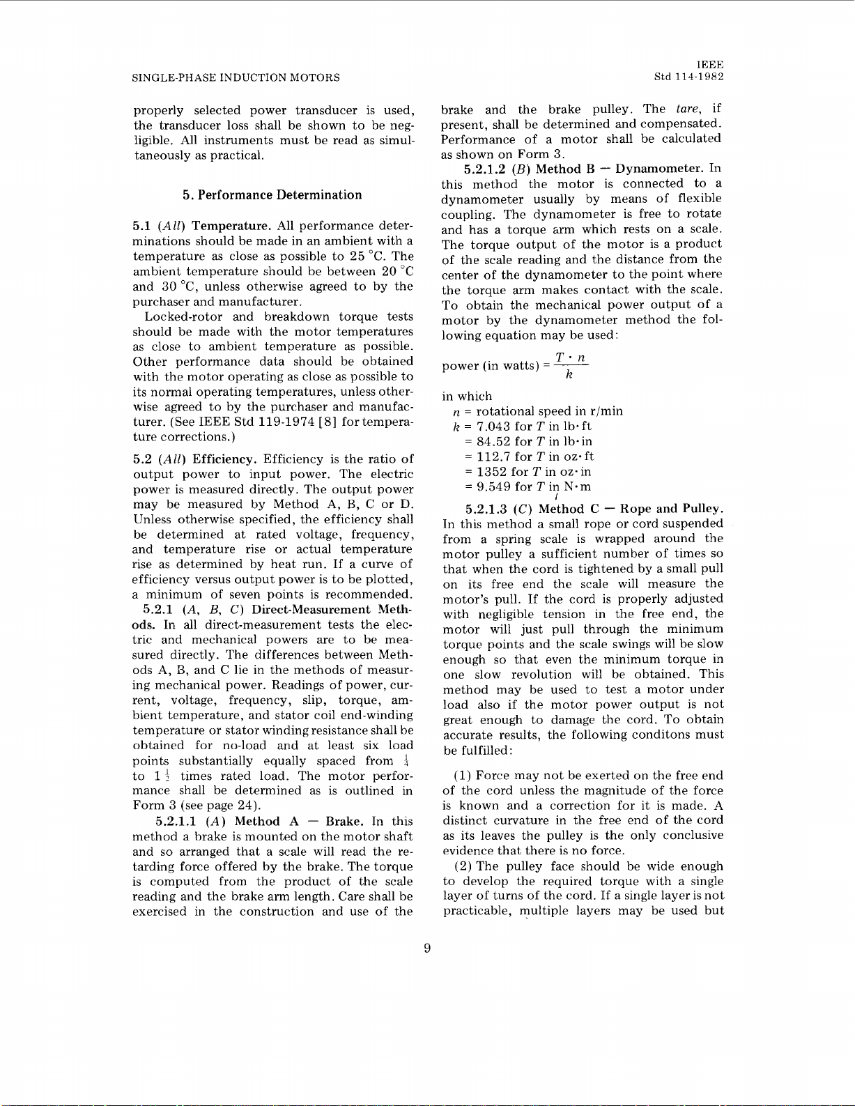
4.6
(All)
Current. The line current
of
the
motor shall be measured by an accurate am-
IEEE STANDARD TEST PROCEDURE FOR
Fig
1
Preferred Meter Arrangement
meter or current transducer. The circuit diagram, Fig
l,
shows the preferred arrangement
of meters.
The motor current is the line current corrected by subtracting from it the currents
taken by the voltmeter and the wattmeter voltage coils and may be computed by using one of
the following equations:
c2
P=P,
--
0-
RM
But
I*>7--
E
RM
may be used.
In these equations
IA
=
current (in amperes) indicated by ammeter
A
I
=
net current, true input to motor
P,
=
power (in watts) indicated by watt-
W
meter
P=
net power (in watts) true input to
motor
E
=voltage (in volts) indicated by volt-
V
meter
RM
=resistance (in ohms) of the voltmeter
and wattmeter voltage coils in parallel
4.7
(All)
Power. A single-phase wattmeter or
power transducer shall be used. The total watts
read on the wattmeter, which shall be connected as shown in 5.5, shall be reduced by the
amount of the power lost in the voltage circuit of the instruments unless the wattmeter
is of the self-compensating type. Where a
SINGLE-PHASE INDUCTION
MOTORS
Std
IEEE
114-1982
properly selected power transducer is used,
the transducer loss shall be shown to be neg-
ligible. All instruments must be read as simultaneously as practical.
5.
Performance Determination
(All)
5.1
Temperature. All performance determinations should be made in an ambient with a
temperature as close as possible to 25 "C. The
ambient temperature should be between 20
"C
and 30 OC, unless otherwise agreed to by the
purchaser and manufacturer.
Locked-rotor and breakdown torque tests
should be made with the motor temperatures
as close to ambient temperature as possible.
Other performance data should be obtained
with the motor operating as close as possible to
its normal operating temperatures, unless otherwise agreed to by the purchaser and manufac-
[8]
turer. (See IEEE Std 119-1974
for tempera-
ture corrections.)
(All)
5.2
Efficiency. Efficiency is the ratio of
output power to input power. The electric
power is measured directly. The output power
may be measured by Method
A,
B, C
or
D.
Unless otherwise specified, the efficiency shall
be determined at rated voltage, frequency,
and temperature rise or actual temperature
rise as determined by heat run. If a curve of
efficiency versus output power is to be plotted,
a minimum of seven points is recommended.
(A,
B,
C)
5.2.1
Direct-Measurement Methods. In all direct-measurement tests the electric and mechanical powers are to be measured directly. The differences between Meth-
B,
ods A,
and C lie in the methods of measuring mechanical power. Readings of power, current, voltage, frequency, slip, torque, ambient temperature, and stator coil end-winding
temperature or stator winding resistance shall be
obtained for no-load and at least six load
points substantially equally spaced from
to
1
f
times rated load. The motor perfor-
4
mance shall be determined as is outlined in
Form
3
(see page 24).
5.2.1.1
(A)
Method
A - Brake. In this
method a brake is mounted on the motor shaft
so
and
arranged that a scale will read the retarding force offered by the brake. The torque
is computed from the product of the scale
reading and the brake arm length. Care shall be
exercised in the construction and use of the
tare,
brake and the brake pulley. The
if
present, shall be determined and compensated.
Performance of a motor shall be calculated
(B)
3.
Method
B
-
Dynamometer. In
as shown on Form
5.2.1.2
this method the motor is connected to a
of
dynamometer usually by means
flexible
coupling. The dynamometer is free to rotate
and has a torque arm which rests on a scale.
The torque output of the motor is a product
of the scale reading and the distance from the
center of the dynamometer to the point where
the torque arm makes contact with the scale.
To obtain the mechanical power output of a
motor by the dynamometer method the following equation may be used:
power (in watts)
T-n
=
__
k
in which
n
=
rotational speed in r/min
k
=
7.043 for Tin lb-ft
=
84.52 for Tin lb-in
=
112.7 for Tin oz-ft
=
1352 for T in oz-in
=
9.549 for Tin N-m
5.2.1.3
(C)
1
Method
C
-
Rope and Pulley.
In this method a small rope or cord suspended
from a spring scale is wrapped around the
motor pulley a sufficient number of times
so
that when the cord is tightened by a small pull
on its free end the scale will measure the
motor's pull. If the cord
is
properly adjusted
with negligible tension in the free end, the
motor will just pull through the minimum
torque points and the scale swings will be slow
enough
so
that even the minimum torque in
one slow revolution will be obtained. This
method may be used to test a motor under
load also if the motor power output is not
great enough to damage the cord. To obtain
accurate results, the following conditons must
be fulfilled
(1)
:
Force may not be exerted on the free end
of the cord unless the magnitude of the force
is known and a correction for
is made.
A
it
distinct curvature in the free end of the cord
as its leaves the pulley is the only conclusive
evidence that there is no force.
(2) The pulley face should be wide enough
to develop the required torque with a single
layer of turns of the cord. If a single layer is not
practicable, multiple layers may be used but
IEEE
Std
114-1982
IEEE STANDARD TEST PROCEDURE
FOR
the first two turns on the scale end of the cord
must be single-layer.
(3)
The pulley must be in proper alignment
with the scale
so
that there is no scale error
caused by a nonrecording component of force
in the cord. The alignment must also be such
that there is a clearance between the cord and
the pulley flange.
5.2.1.3.1
Method C -Correction for Cord
Diameter. In calculating the torque, the radius
at which the force is applied is to be taken
as the pulley radius plus the cord radius.
The cord diameter should be measured with
the cord under tension. The micrometer anvil
and spindle should have flat faces large enough
to span at least two strand pitches. Sufficient
pressure should be applied to flatten minor
irregularities in the cord. Inasmuch
as
the
cord diameter may change because of wear
or stretch, the ratio of cord diameter to pulley
diameter should be as small as practicable.
5.2.1.3.2
Method C - Correction for Pulley Windage Loss or for Dynamometer Windage
Loss. The measured values of torque are to be
corrected by adding to them a torque corresponding to the pulley windage or the
dynamometer windage loss. The allowance for
this loss is made by adding a torque Tw
Tw
=
k(PA
-
PB)_
T
n
D
:
in which
PA
=watts input to the motor driving the
pulley or dynamometer
PB
=
watts input to the motor without the
pulley or dynamometer
n
=
rotational speed in r/min
k
=
7,043
for T in lb- ft
=
84.52
for Tin lb-in
=
112.7
=
1352
=
9.549
5.2.1.3.3
for Tin
for Tin oz.in
for Tin N-m
Method
OZ-ft
C
-
Determination of
Friction and Windage Loss. When motors are
supplied without bearings by the motor manufacturer it may be desirable to quote the efficiencies on the basis of a specified friction
and windage loss and to consider the losses to
be charged against the driven device. In such a
to
case it is the usual practice
jig
or fixture which does have friction in the
a
test the parts in
bearings. The amount of this friction and wind-
is
age
then separately determined and added
to the motor output. For accurate results, the
friction of this jig or fixture should be low
even though a correction is made inasmuch
as
the jig friction may change while a test is
in progress.
5.2.1.3.4
Method C - Dynamometer Method of Measuring Friction and Windage. One
method of determining the friction and windage losses is to measure the torque required to
drive the parts at normal speed by means of
Pf
a dynamometer. The friction
is then ex-
pressed, in watts, as:
Tf
=
7
n
Pf
in which
=
net friction torque
Tf
k
=
same values
n
=
rotational speed in r/min
as
used in
5.2.1.3.2
The dynamometer used for this test should
be such that the measured friction torque Tf
represents at least
15%
of the normal torque
capacity of the dynamometer.
5.2.1.3.5
Method C - No-Load Satura-
tion Method of Determining Friction and
Loss.
Windage
The motor is run at no-load
at normal frequency and voltage until the
power input is constant to assure that the
temperature of the oil or grease and the bearing friction have become constant. Readings
are taken of volt, ampere, and watt input at
rated frequency but with voltages ranging
from
125%
of rated voltage down to a point
where further voltage reduction increases the
current. The voltage adjustment is accomplished preferably by a variable-voltage transformer. Immediately following this test and
before the temperatures can change sensibly,
a reading of input power
I,
at
50%
or
60%
Pf
and input current
of rated voltage should be
taken with the rotor locked and with only
the main or running winding excited. This
test should be followed immediately by a
RI
measurement of the stator resistance
If the input current at any voltage is
P,
total copper loss
voltage is:
I
The copper loss
in the machine at the same
so
calculated should be sub-
.
I,,
the
tracted from the total input power at the same
voltage. The resultant values may then be
plotted against applied voltage with an extrap-
10
 Loading...