

Page 1
S-AIT
Tape Drive Unit
4-680-196-13 (2)
Operating Instructions Page 5 _________________________________
Important Safeguards Page 50 ________________________________
SDZ-S100
SDZ-S130
© 2003 Sony Corporation
Page 2

Owner’s Record
The model and serial numbers are on a label on the bottom of the unit.
Record the serial number in the space provided below. These numbers provide specific information about your S-AIT
Tape Drive Unit and will be very helpful if you have to contact technical support.
Model No.
Serial No.
Safety Information
Your S-AIT Tape Drive Unit is assigned model number SDZ-S100 or SDZ-S130 for regulatory
compliance certifications. The number is indicated on the model number label on your drive along with
the rated voltage and current.
WARNING
To reduce the risk of fire or electric shock, do not expose this apparatus to rain or moisture.
To avoid electrical shock, do not open the cabinet.
Refer servicing to qualified personnel only.
Caution
The mains plug on this equipment must be used to disconnect mains power.
Please ensure that the socket outlet is installed near the equipment and shall be easily accessible.
Notice
Use the power cord set approved by the appropriate testing organization for the specific countries where this unit is to be
used.
Achtung
Zur Trennung vom Netz ist der Netzstecker aus der Steckdose zu ziehen, welche sich in der Nähe des Gerätes befinden
muß und leicht zugänglich sein soll.
Hinweis
Die 3-adrige Geräteanschlußleitung muß Typ H05VV-F oder H05VVH2-F sein und nach DIN VDE 0625 geprüft sein.
Der Stecker und die Gerätesteckdose müssen nach DIN VDE 0620 bzw DIN VDE 0625 geprüft sein. Der
Leitungsquerschnitt kann 0,5mm
Anderenfalls muß der Leitungsquerschnitt mindestens 0,75mm
2
betragen wenn die Anschlußleitung eine Länge von 2m nicht überschreitet.
2
betragen.
Hinweis
Maschinenlärminformations-Verordnung - 3. GPSGV, der höchste Schalldruckpegel beträgt 70 dB(A) oder weniger
gemäss EN ISO 7779.
Ratings
Voltage
AC 100 V - 240 V
Current
0.7 A - 0.4 A
Frequency
50 / 60 Hz
Max. Ambient Temperature
35 degrees centigrade
2
Page 3

A certified power supply cord has to be used with this equipment.
The relevant national installation and/or equipment regulations shall be considered.
A certified power supply cord not lighter than ordinary polyvinyl chloride flexible cord according to IEC 60227
(designation H05VV-F 3G 0.75 mm
synthetic rubber according to IEC 60245 (designation H05RR-F 3G 0.75 mm
Zum Netzanschluss dieses Gerätes ist eine geprüfte Leitung zu verwenden.
Es sind die zutreffenden nationalen Errichtungs- und/oder Gerätebestimmungen zu beachten.
Es ist eine geprüfte flexible PVC-ummantelte Leitung entsprechend IEC 60227 (H05VV-F 3G 0.75 mm
F 3G 0.75 mm
(Bauartkurzzeichen H05RR-F 3G 0.75 mm
2
) zu verwenden. Andernfalls ist eine flexible Leitung aus synthetischem Gummi entsprechend IEC 60245
2
or H05VVH2-F2 3G 0.75 mm2) shall be used. Alternative a flexible cord be of
2
) zu verwenden.
2
) shall be used.
2
oder H05VVH2-
ATTENTION
According to the EU Directives related to product safety, EMC and R&TTE the manufacturer of this product is Sony
Corporation, 6-7-35 Kitashinagawa Shinagawa-ku Tokyo, 141-0001 Japan. The Authorised Representative is Sony
Deutschland GmbH, Hedelfinger Strasse 61,70327 Stuttgart, Germany. For any service or guarantee matters please refer
to the addresses given in separate service or guarantee documents.
AUFMERKSAMKEIT
Im Sinne der EU Richtlinien bezüglich Produktsicherheit, EMV und R&TTE ist Sony Corporation, 6-7-35 Kitashinagawa
Shinagawa-ku Tokyo, 141-0001 Japan der Hersteller dieses Produktes. Bevollmächtigter ist Sony Deutschland GmbH,
Hedelfinger Strasse 61,D-70327 Stuttgart. Für Service oder Garantieangelegenheiten wenden Sie sich bitte an die in
separaten Service oder Garantiedokumenten angegebenen Adressen.
European Union Restriction of Hazardous Substances Directive compliant.
Entspricht der Richtlinie der Europäischen Union zur Beschränkung der Verwendung gefährlicher
Stoffe.
Laser Notice
(For Model No. SDZ-S130 only)
The equipment contains a tape drive using laser that complies with IEC 60825-1.
The equipment is classified as a CLASS 1 LASER PRODUCT.
Caution
The use of controls or adjustments or performance of procedures other than those specified herein may result in
hazardous radiation exposure.
Caution
Do not look at the end of optical connecor on the back of the tape drive with naked eyes or through optical equipment
while the power is supplied to this product. Otherwise, your eyes may be injured.
Bei diesem Laufwerk handelt es sich um ein Laser-Produkt der Klasse 1.
INFORMATION
You are cautioned that any changes or modifications not expressly approved in this manual could void your authority to
operate this equipment.
Note: This equipment has been tested and found to comply with the limits for a Class B digital device, pursuant to Part 15
of the FCC Rules. These limits are designed to provide reasonable protection against harmful interference in a residential
installation.
3
Page 4
This equipment generates, uses, and can radiate radio frequency energy and, if not installed and used in accordance with
the instructions, may cause harmful interference to radio communications. However, there is no guarantee that interference
will not occur in a particular installation. If this equipment does cause harmful interference to radio or television reception,
which can be determined by turning the equipment off and on, the user is encouraged to try to correct the interference by
one or more of the following measures:
• Reorient or relocate the receiving antenna.
• Increase the separation between the equipment and receiver.
• Connect the equipment into an outlet on a circuit different from that to which the receiver is connected.
• Consult the dealer or an experience radio/TV technician for help.
The shielded interface cable recommended in this manual must be used with this equipment in order to comply with the
limits for a digital device pursuant to Subpart B of Part 15 of FCC Rules.
If you have any questions about this product, contact your dealer.
Declaration of Conformity
Trade Name: SONY
Model No.: SDZ-S100, SDZ-S130
Responsible Party: Sony Electronics Inc.
Address: 16530 Via Esprillo San Diego, CA. 92127 U.S.A.
Telephone No.: 858-942-2230
This device complies with Part 15 of the FCC Rules. Operation is subject to the following two conditions:
(1) This device may not cause harmful interference, and
(2) This device must accept any interference received, including interference that may cause undesired operation.
Für Kunden in Deutschland
Diese Ausrüstung erfüllt die Europäischen EMC-Bestimmungen für die Verwendung in folgender/folgenden
Umgebung(en):
• Wohngegenden
• Gewerbegebiete
• Leichtindustriegebiete
(Diese Ausrüstung erfüllt die Bestimmungen der Norm EN55022, Klasse B.)
For Users in Japan
For Users in Korea
4
Page 5

Table of Contents
Chapter 1 Introduction
Chapter 2 Installation
Overview.......................................................................7
S-AIT Technology........................................................7
Product Features.........................................................8
Compatible Cartridges................................................9
Data Cartridges ...............................................................9
Cleaning Cartridges......................................................... 9
Supported Software ....................................................9
Components and Functions.....................................10
Front.............................................................................. 10
Rear ...............................................................................13
Bottom........................................................................... 15
About the label...........................................................16
Overview.....................................................................17
Unpacking ..................................................................17
Package Contents .....................................................18
Preparing the Host Computer ..................................18
Setting the DIP Switches ..........................................19
If necessary, change the settings as follows..................19
Setting the SCSI ID (SDZ-S100 only) .......................22
Setting the Loop ID (SDZ-S130 only).......................23
Installing the S-AIT Tape Drive Unit.........................25
Connecting the Power Cable....................................26
Installing Device Drivers...........................................26
Connecting the SCSI Bus Cable
(SDZ-S100 only) ..................................................27
Connecting the Optical Fiber Cable for
Fibre Channel (SDZ-S130 only) ........................29
Configuring the S-AIT Tape Drive Unit to
the Host ...............................................................30
Chapter 3 Operation
Overview.....................................................................31
Turning the Unit On or Off........................................31
Turning On the Unit...................................................... 31
Turning Off the Unit .....................................................33
Preparing Cartridges.................................................33
Inserting a Cartridge .................................................33
Removing a Cartridge ...............................................34
5
Page 6

Chapter 4 Using the Media
Appendix
Compatible Cartridges..............................................35
Data Cartridge............................................................35
Components and Functions........................................... 36
Setting the Write-protect Switch..............................38
Cleaning Cartridge ....................................................38
Handling Cartridges ..................................................39
Usage, Storage, and Transport Environmental
Specifications .....................................................40
Head Cleaning............................................................41
Changing the Air Filter Unit......................................42
Hardware Reset .........................................................43
Updating the Firmware..............................................43
Taking Care of the Unit .............................................43
Safety ............................................................................43
Avoiding Damage .........................................................44
Troubleshooting ........................................................45
Specifications ............................................................47
Performance ..................................................................47
Environmental Specifications .......................................47
Power Specifications/Miscellaneous.............................48
Options.......................................................................48
Index ...........................................................................49
© 2003 Sony Corporation. All rights reserved.
Trademarks
• Sony, Advanced Intelligent Tape, and Super Advanced Intelligent Tape are trademarks or registered trademarks of Sony
Corporation in this country, other countries, or both.
• Other product names are trademarks or registered trademarks of their respective owners in this country, other countries,
or both.
6
Page 7

Overview
S-AIT Technology
Introduction
The S-AIT Tape Drive Unit is a tape streamer that makes use of “S-AIT” (Super
Advanced Intelligent Tape) technology. The S-AIT drive stores large amounts
of image data on a single half-inch tape cartridge, making it the industry's
highest capacity tape drive.
Helical Scan Recording Technology
Helical scan technology, based on a very stable rotating drum/head platform,
permits accurate and reliable data recording at very high track densities. This
efficient packing density provides the industry’s leading, space-efficient
solution.
Chapter
1
Advanced Metal Evaporated (AME) Tape
S-AIT media is based on AME technology. This technology represents the
culmination of over 50 years of Sony innovation and experience in magnetic
tape technology. The AME tape formulation, with diamond-like carbon coating,
offers an extraordinary durability and reliability, up to 30,000 media passes, and
an estimated media archival life of up to 30 years.
Remote Memory in Cassette (R-MIC)
The non-volatile R-MIC chip built into the data cartridge provides quick media
loads and allows fast searches of data. The R-MIC chip contains the tape’s
system log, search map and user-definable information, allowing the drive to
advance at high speed directly to any file on the tape.
Reliability
The reliability of the S-AIT drive is in part the due to its innovative features,
such as its automatic head cleaning system and effective “leader block” tape
threading system with simplified tape load path. The drive cooling system is
also isolated from the sealed tape mechanism, thereby preventing airborne
contaminants from entering the tape path and affecting sensitive components.
Chapter 1 Introduction
7
Page 8

Product Features
Two models of S-AIT Tape Drive Units are available according to the type of
interface of your host computer.
SDZ-S100
Uses the Ultra 160 Wide Low Voltage Differential/Single-Ended (LVD/SE)
SCSI
SDZ-S130
Uses 2 Gbps Fibre Channel interface
Common Features
• Native storage capacity of 500 GB per cartridge (1.3 TB at 2.6:1 compression)
with the S-AIT data cartridge SAIT1-500.
• Native sustained data transfer rate of 30 MB per second.
• High data reliability with the Read After Write and Fragment Rewrite
functions, and the three levels of Error Correction Code (ECC).
• Possibility to enable and disable the Read After Write (RAW) function.
• High-speed search and tape rewind.
• Supports variable and fixed record length.
• 72 MB buffer memory.
• Very compact design that allows you to set two units side by side on a 19-inch
rack (2U height).
• Sealed mechanism with the front door and the air filter.
• Very easy to change the air filter.
• Half transparent front panel through which you can verify the cartridge even
when the door is closed.
• Sleek and elegant design.
Features of the SDZ-S100 (SCSI model)
• Ultra 160 SCSI LVD/SE interface is fully supported for host computer access.
• Burst data transfer rate of 160 MB per second, synchronous.
• Supports SCSI disconnection and arbitration.
Features of the SDZ-S130
(Fibre Channel Interface model)
• 2 Gbps Fibre Channel interface.
• 200 MB per second burst data transfer rate.
• Private Loop, Public Loop, Point-to-Point, and Switched Fabric topologies.
• Full-duplex transfers.
• FCP2 support.
• Class of service: Class 3
8
Chapter 1 Introduction
Page 9
Compatible Cartridges
Data Cartridges
Tape cartridges used with the S-AIT Tape Drive Unit must be marked with the
SAIT-1 logo.
SAIT-1 logo
Caution
Only use cartridges designed specifically for S-AIT.
Cleaning Cartridges
To clean the read/write heads, use the S-AIT Cleaning Cartridge. For details
about cleaning, see “Head Cleaning” on page 41.
Supported Software
For details about software that can be used with the S-AIT Tape Drive Unit and
supported operating systems, contact your dealer.
Chapter 1 Introduction
9
Page 10
Components and Functions
Front
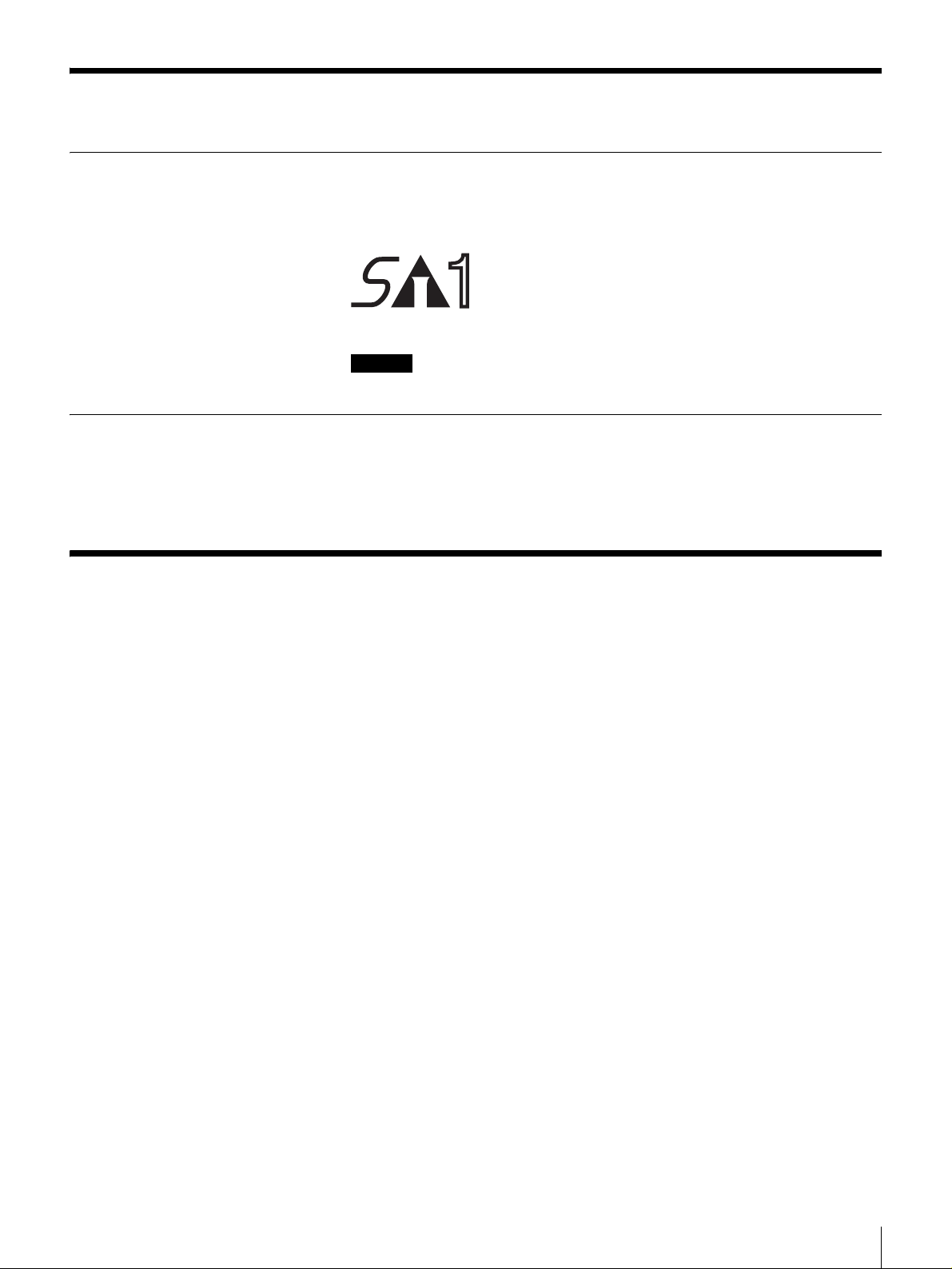
A Front Door
Used to protect the front of the unit. Press the DOOR button to unlock and open
the door when inserting or removing cartridges.
Note
Even when the front door is closed and a cartridge is ejected by software, the
cartridge does not come in contact with the door. You can therefore keep the
door closed except when inserting or removing cartridges to minimize any
contamination from airborne particles.
MOTION
OPEN
TAPE
DRIVE
TAPE
ERROR
CLEANING
REQUEST
ERROR
B DOOR Button
Press to open the front door.
10
Chapter 1 Introduction
Page 11
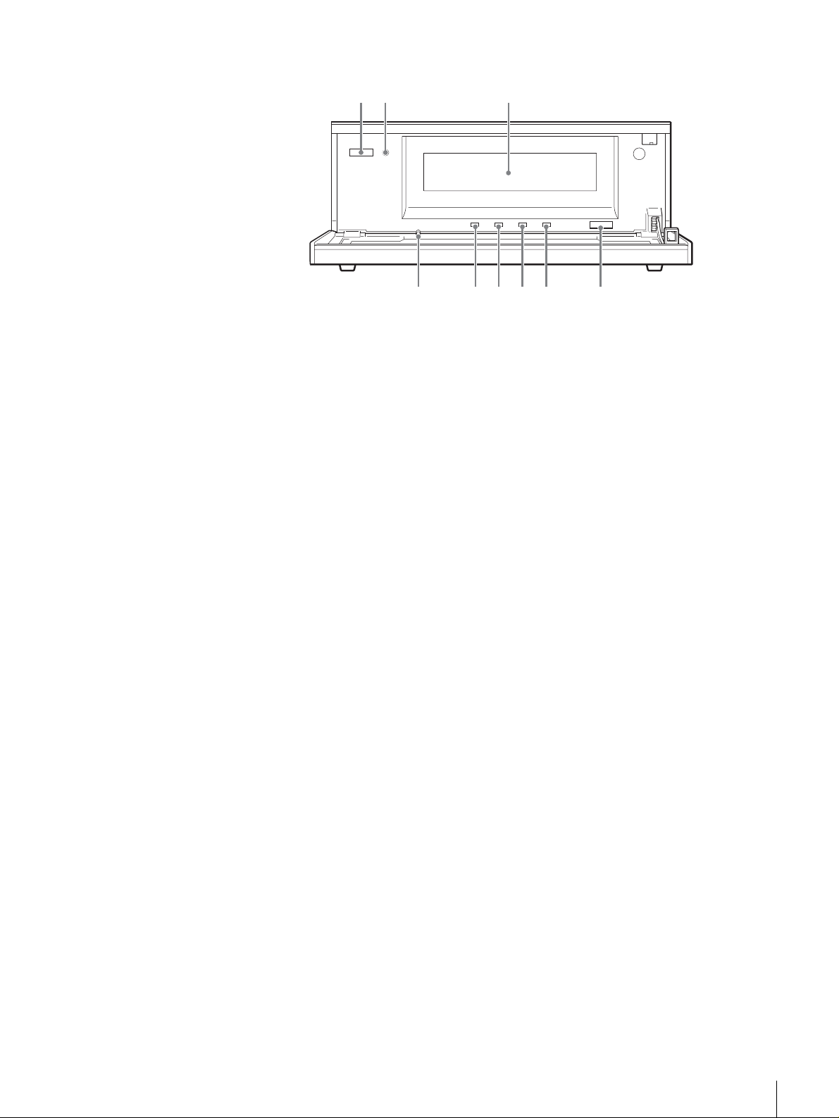
Front door opened
1 2 3
456789
A Power Switch
Press this switch to turn the S-AIT Tape Drive Unit on or off. When you restart
the unit, be sure to wait at least 10 seconds before turning it on again.
B POWER Indicator
Lights green when the unit is on. When it flashes, the cooling fan of the unit may
be malfunctioning. If this is the case, verify that the cooling fan on the rear is
operating normally. If it is not, contact your dealer.
C Cartridge Slot
Used to insert and remove cartridges.
D Eject Button
Push to manually eject cartridges from the unit. The unit ejects cleaning
cartridges automatically.
E CLEANING REQUEST Indicator
Flashes yellow when the read/write heads need cleaning. For details about
cleaning, see “Head Cleaning” on page 41.
F TAPE ERROR Indicator
Flashes or lights orange when media errors occur. When media warnings occur,
the indicator flashes yellow. In this case, copy data to another cartridge.
G DRIVE ERROR Indicator
Flashes orange or yellow when drive errors occur.
H TAPE MOTION Indicator
Lights when you insert cartridges. The color of the indicator, shows whether the
cartridge is write-protected. Moreover, when the unit is operating, the indicator
flashes. The color of the flashing indicator shows the status of the unit.
I Hardware Reset Hole
Used to reset the unit in case of emergency. Using the emergency reset hole
when reading or writing data may damage your data, therefore this procedure
should only be used for maintenance purposes.
Chapter 1 Introduction
11
Page 12
Drive Status
The indicators of the S-AIT Tape Drive Unit show the status of the unit. This
status is indicated by a combination of colors (green, orange, or yellow), and
whether the indicators are lit or flashing. Refer to the table below for
explanations about the meaning of indicator activity.
CLEANING
REQUEST
No cleaning
request
All green,
flashing
All green, lit
Orange,
flashing
Orange, lit
Yellow,
flashing
Yellow, lit
Green,
flashing
Green, lit
Off
TAPE MOTION DRIVE ERROR TAPE ERROR
Firmware update
Ejection inhibited (only when pressing the eject button)
Tape being
accessed (write)
⎯⎯Media error ⎯
Tape being
accessed
(search)
Tape loaded
(write-protected)
Tape being
accessed (read)
Tape loaded
(write-enabled)
No tape No drive error No media error
Drive error Media error Cleaning error
Drive error Media warning Cleaning request
⎯⎯Cleaning
⎯⎯⎯
⎯⎯⎯
Note
When you turn on the unit or reset it, all the indicators light green for about half
a second. They then flash repeatedly yellow from left to right for about 3
seconds, indicating that the unit is performing a self-diagnostic.
12
Chapter 1 Introduction
Page 13
Rear
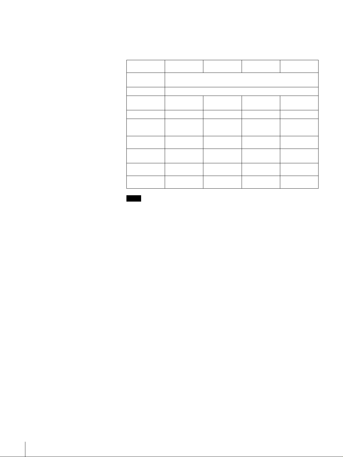
SDZ-S100
A SCSI ID Switch
Used to set the SCSI ID of the S-AIT Tape Drive Unit. Upon shipment, the SCSI
ID is 0. For details, see “Setting the SCSI ID (SDZ-S100 only)” on page 22.
B RS-232C Connector
For service use only. You do not normally need to use this connector.
C Cooling Fan and Ventilation Holes
Be careful not to block the ventilation holes. If you do, the unit may overheat,
resulting in damage.
D AC IN Connector
Connect the power cable appropriate for your country to this connector.
E Ventilation Holes
Be careful not to block the ventilation holes. If you do, the drive in the unit may
overheat, resulting in damage.
F SCSI Connector 1, 7 SCSI Connector 2
Connect the SCSI bus cable to this connector. For details about connection, see
“Connecting the SCSI Bus Cable (SDZ-S100 only)” on page 27.
Chapter 1 Introduction
13
Page 14
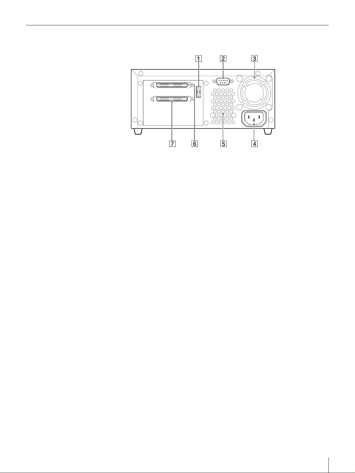
SDZ-S130
1 2
346 57
A RS-232C Connector
For service use only. You do not normally need to use this connector.
B Cooling Fan and Ventilation Holes
Be careful not to block the ventilation holes. If you do, the unit may overheat,
resulting in damage.
C AC IN Connector
Connect the power cable appropriate for your country to this connector.
D Ventilation Holes
Be careful not to block the ventilation holes. If you do, the drive in the unit may
overheat, resulting in damage.
E FC Status Indicator
When the fibre channel connection is normal, the indicator is off. When the unit
is communicating with the host computer, this indicator lights green. When
there is a connection error, the indicator lights orange. In this case, reconnect the
cable or change it if necessary.
F Loop ID Jumpers
These jumpers are functional when the topology is arbitrated loop. For details,
see “Setting the Loop ID (SDZ-S130 only)” on page 23.
G Fibre Channel Connector
Connect the optical fiber cable for Fibre Channel. For details about connection,
see “Connecting the Optical Fiber Cable for Fibre Channel (SDZ-S130 only)”
on page 29.
14
Chapter 1 Introduction
Page 15
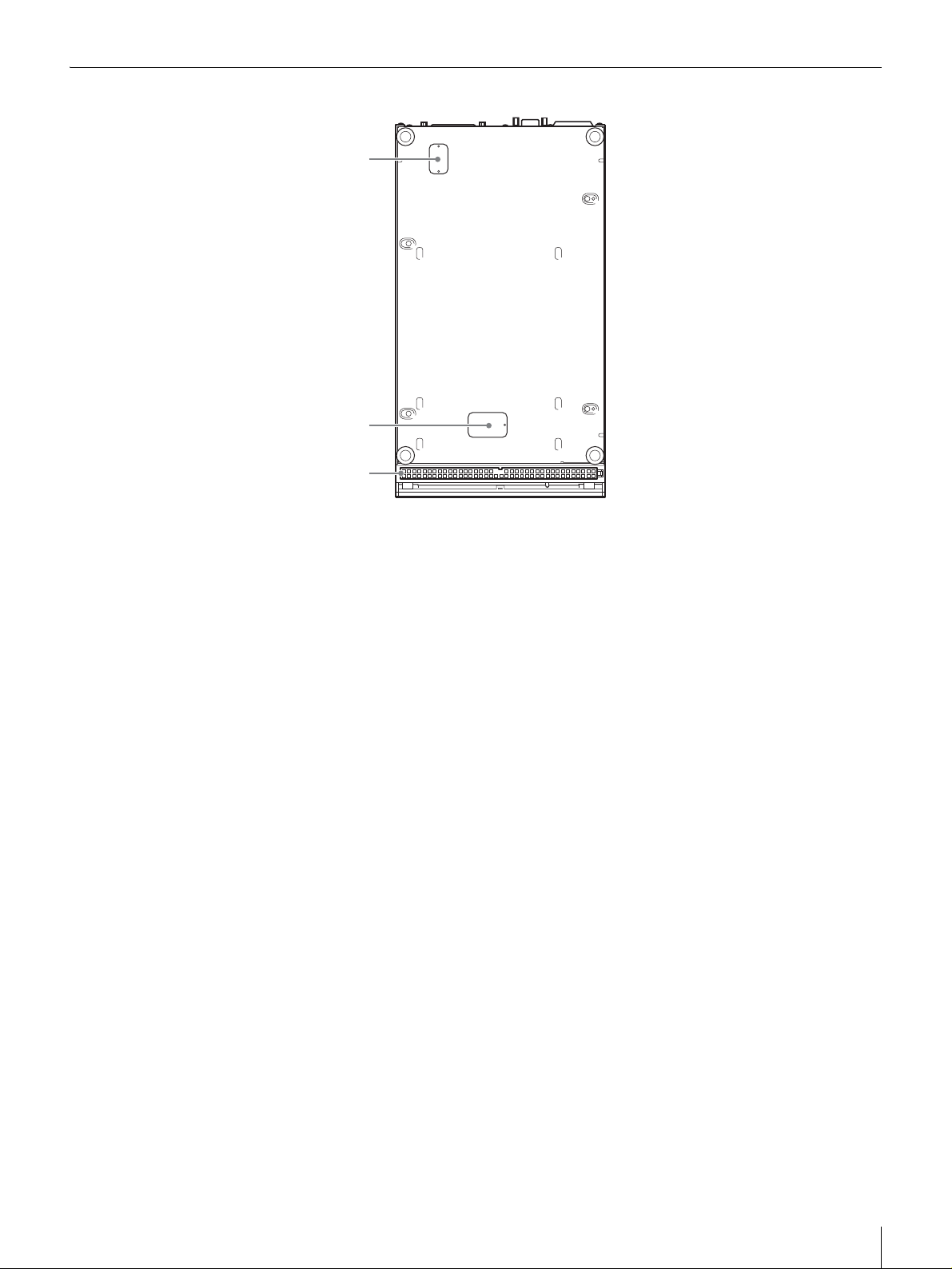
Bottom
1
2
3
A Access Cover for Service Use
Do not open this cover. For service use only.
B Dip Switch Access Cover
If you need to change the data compression settings, remove this cover to
change the DIP switch settings. For details about setting the DIP switches, see
“Setting the DIP Switches” on page 19.
C Air Filter Unit
Be careful not to block the ventilation holes of the air filter unit. If you do, the
S-AIT Tape Drive Unit may overheat, resulting in damage. Moreover,
periodically clean the air filter unit with a vacuum cleaner (monthly cleanings
recommended) and replace it yearly. For details about how to replace the air
filter unit, see “Changing the Air Filter Unit” on page 42.
Chapter 1 Introduction
15
Page 16
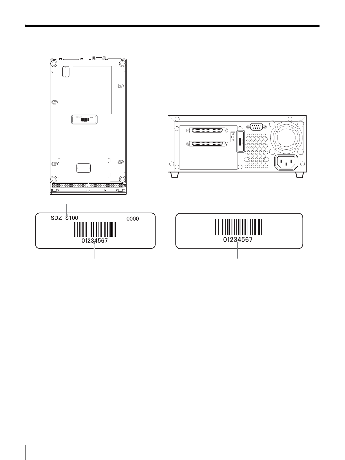
About the label
2 3
1
A Model number
The model number is located on the bottom of the unit, together with the serial
number.
Refer to the model and serial numbers on the label when seeking technical
support.
B Serial number
The serial number is located on the bottom of the unit, together with the model
number.
Refer to the serial and model numbers on the label when seeking technical
support.
C Number returned to the interface command
The number, which is returned to the interface command, is located on the rear
of the unit. This is the serial number reported by the application software you
use.
16
Chapter 1 Introduction
Page 17
Overview
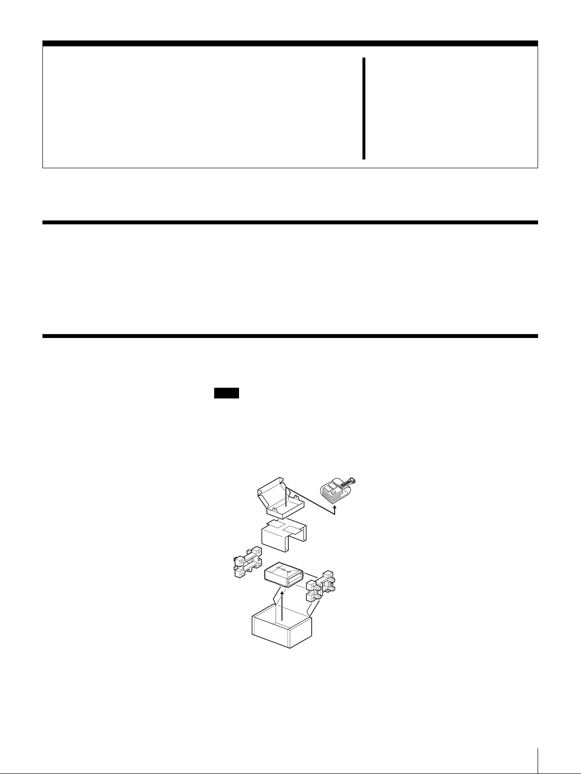
Unpacking
Installation
This chapter describes the general procedures for positioning the S-AIT Tape
Drive Unit, connecting it to the host computer, and turning it on. This chapter
also describes initial setup. Installation and setup procedures may vary slightly
depending on your system.
Note
You will need the box and packing materials if you wish to move or transport
the unit. Retain them for future use.
Chapter
2
1
Remove the unit from the box as indicated below.
Remove the packing materials, such as plastic covers and tapes.
2
Inspect the unit for shipping damage.
If there is damage, do not use the unit. Report the damage immediately by
contacting your dealer.
Chapter 2 Installation
17
Page 18

Package Contents
After opening the package, make sure that all the following items are present.
Contact your dealer if anything is missing.
• S-AIT Tape Drive Unit (1)
• Operating Instructions (1)
Note
In addition to the above, other items may be included in the package.
Preparing the Host Computer
Prepare the host computer before installing the S-AIT Tape Drive Unit.
1
Make sure that a SCSI host adapter card or Fibre Channel host bus adapter
(FC HBA) is installed in the host computer.
2
Install all the necessary software supporting the unit on the host computer.
For details about the software that can be used with the S-AIT Tape Drive
Unit and supported operating systems, contact your dealer.
18
Chapter 2 Installation
Page 19
Setting the DIP Switches
By setting the DIP switches at the bottom of the S-AIT Tape Drive Unit, you
can:
• Choose whether to compress the data when recording.
• Choose whether the host can control data compression.
The default settings of the DIP switches is as follows.
• DC Control-1: ON
Compression is enabled.
• DC Control-2: OFF
The host can control compression.
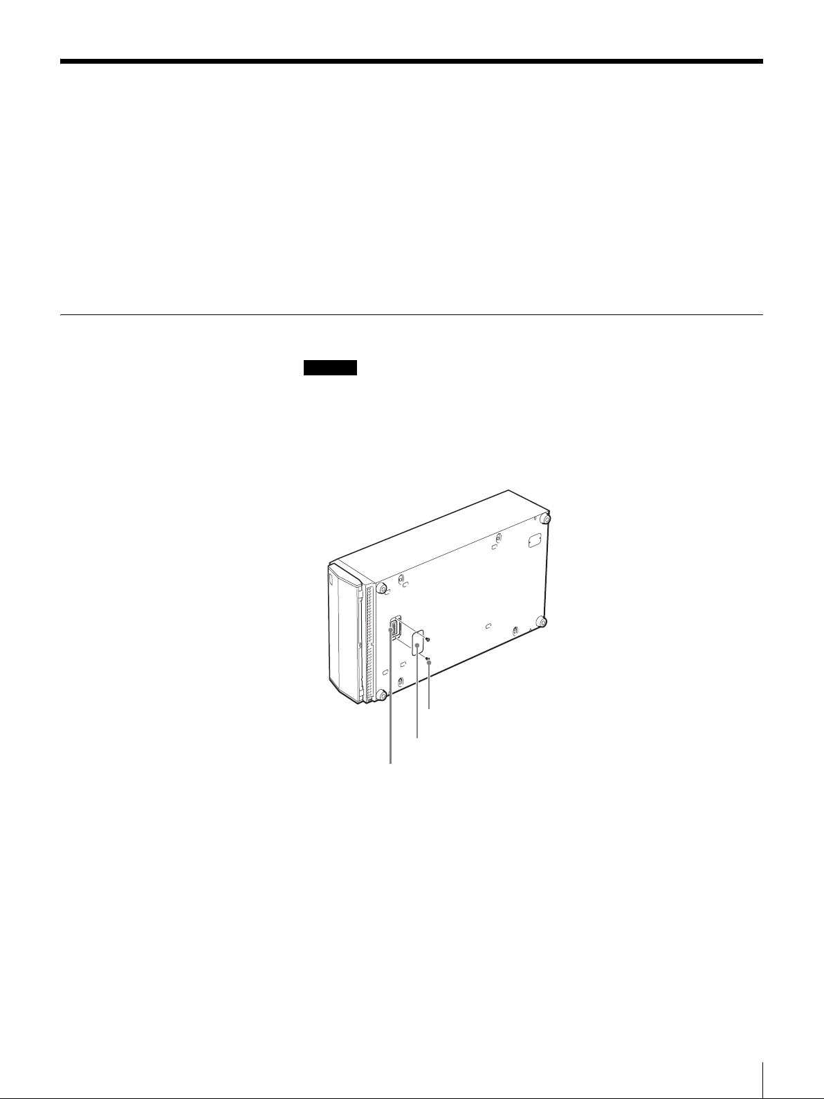
If necessary, change the settings as follows
Caution
Before removing the access cover to change DIP switch settings of the S-AIT
Tape Drive Unit, turn off the unit and disconnect the power cable.
1
Make sure that the unit is off.
2
Remove the two screws with a screwdriver and remove the access cover.
Screw
Access cover
DIP switches
Chapter 2 Installation
19
Page 20
3
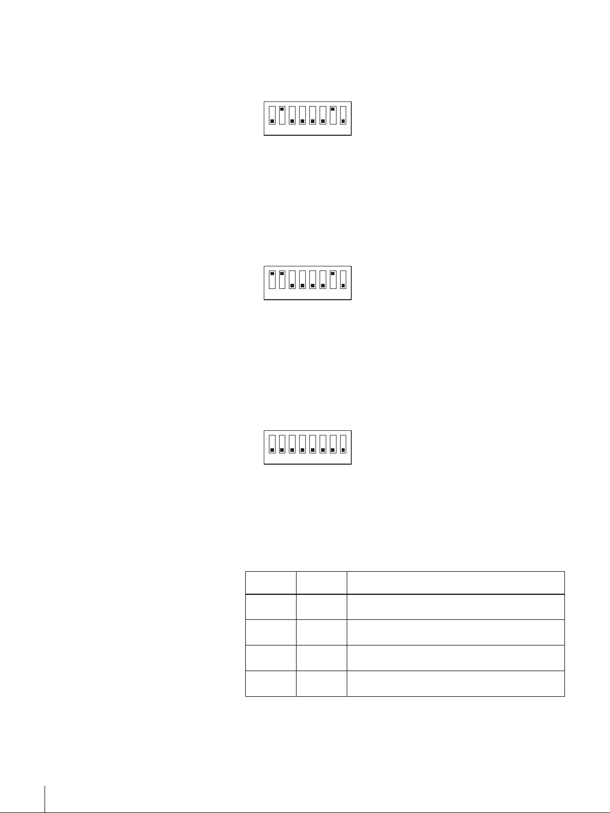
Change the settings with a pointed object.
Each DIP switch is defined in the tables below.
SWA settings (SDZ-S100)
SWA (SDZ-S100)
ON
OFF
12345678
SWA (SDZ-S130)
ON
OFF
12345678
SW1 Custom-1 OFF
SW2 Block Size ON
SW3 Immediate WFM OFF
SW4 Custom-4 OFF
SW5 Reserved OFF
SW6 Reserved OFF
SW7 DC Control-1 ON
SW8 DC Control-2 OFF
SWA settings (SDZ-S130)
SW1 UA Control ON
SW2 Block Size ON
SW3 Immediate WFM OFF
SW4 Custom-4 OFF
SW5 Reserved OFF
SW6 Reserved OFF
SW7 DC Control-1 ON
SW8 DC Control-2 OFF
SWB
ON
OFF
12345678
DC
Control-1
OFF OFF
OFF ON
ON OFF
ON ON
DC
Control-2
SWB settings (Common)
SW1 Reserved OFF
SW2 Reserved OFF
SW3 Reserved OFF
SW4 Reserved OFF
SW5 Reserved OFF
SW6 Reserved OFF
SW7 Reserved OFF
SW8 Reserved OFF
Definition
Compression disabled. The host can control
compression.
Compression disabled. The host cannot control
compression.
Compression enabled. The host can control
compression.
Compression enabled. The host cannot control
compression.
20
Chapter 2 Installation
Page 21

Block Size Definition
OFF
ON
Default is 512 byte block size fix mode.
Default is variable mode.
Immediate
WFM
OFF
ON
UA Control Definition
OFF
ON
4
After changing the DIP switch settings, replace the access cover.
Enable Immed bit field in WRITE FILEMARKS command.
Ignore Immed bit field, and always return good status
immediately.
Enable to report UnitAttention (UA) sense.
Disable to report UnitAttention (UA) sense under AIX/IRIX
environment.
Definition
If you are using a SDZ-S100 (SCSI model), proceed to “Setting the SCSI ID
(SDZ-S100 only)” on page 22.
If you are using a SDZ-S130 (Fibre Channel interface model), proceed to
“Setting the Loop ID (SDZ-S130 only)” on page 23.
Chapter 2 Installation
21
Page 22

Setting the SCSI ID (SDZ-S100 only)
The SCSI ID is a unique address that identifies the SDZ-S100 to the host. The
default SCSI ID of the SDZ-S100 is 0. The unit can be configured to SCSI ID
addresses ranging from 0 to 15 (or 0 to F) using the SCSI ID switch on the rear
of the unit. Press the switch buttons to select the necessary SCSI ID number.
Caution
• The range of SCSI IDs is 0 to 15 (or 0 to F). SCSI ID priority is 7 (highest) to
0, and then 15 (or F) to 8 (lowest).
• The SCSI ID must be different from the IDs of other peripherals on the SCSI
bus.
• Do not select the SCSI ID of the SCSI host adapter card. The priority of this
ID is usually higher than that of any device on the SCSI bus. Generally, the
SCSI ID of the host adapter is 7.
• Perform this setting before turning on the unit.
1
Before changing the SCSI ID, turn off the unit.
2
Press the button above and below the ID number with a pointed object such
as a ballpoint pen to select the SCSI ID that you want.
0
0
3
The new ID becomes effective when you restart the unit or reset the SCSI
bus.
When you are done, proceed to “Installing the S-AIT Tape Drive Unit” on page
25.
22
Chapter 2 Installation
Page 23

Setting the Loop ID (SDZ-S130 only)
You can set the Loop ID with the loop ID jumpers, if necessary. These jumpers
are functional when the topology is arbitrated loop. When the jumpers are
enabled, they acquire AL_PA through LIHA (Loop Initialization Hard
Assigned). AL_PA is acquired from the loop ID. See table “Arbitrated Loop
Physical Addresses (AL_PA) and Loop IDs” on page 24 for conversion details.
When the jumpers are disabled, acquisition of AL_PA through LIHA is not
performed, so AL_PA is acquired from LISA (Loop Initialization Soft
Assigned).
Caution
• Turn off the unit before setting the Loop ID with the loop ID jumpers. Failing
to do so may result in damage.
• Do not touch the fibre channel or jumper connectors of the unit when it is on.
Doing so may result in damage.
LOOP ID
210
345
LOOP ID
0
1
2
6
3
4
5
6
121
122
123
124
125
Reserved
Reserved
Fibre channel
connector
Jumpers
LOOP ID 0
LOOP ID 1
LOOP ID 2
LOOP ID 3
LOOP ID 4
LOOP ID 5
LOOP ID 6
LOOP ID Enable
LOOP ID Enable
Enable
Disable
Note: = CLOSED/Jumper
= OPEN/Jumper not installed
= Don't care
Chapter 2 Installation
23
Page 24

Arbitrated Loop Physical Addresses (AL_PA) and Loop IDs
7-bit Loop ID
(Hex) (Decimal) (Hex) (Hex) (Decimal) (Hex) (Hex) (Decimal) (Hex)
00 0 EF 2B 43 A3 56 86 4D
01 1 E8 2C 44 9F 57 87 4C
02 2 E4 2D 45 9E 58 88 4B
03 3 E2 2E 46 9D 59 89 4A
lowest priority
04 4 E1 2F 47 9B 5A 90 49
05 5 E03048985B9147
06 6DC3149975C9246
07 7 DA3250905D9345
08 8 D933518F5E9443
09 9 D63452885F953C
0A 10 D5 35 53 84 60 96 3A
0B 11 D4 36 54 82 61 97 39
0C 12 D3 37 55 81 62 98 36
0D 13 D2 38 56 80 63 99 35
0E 14 D1 39 57 7C 64 100 34
0F 15 CE 3A 58 7A 65 101 33
10 16 CD 3B 59 79 66 102 32
11 17 CC 3C 60 76 67 103 31
12 18 CB 3D 61 75 68 104 2E
13 19 CA 3E 62 74 69 105 2D
14 20 C9 3F 63 73 6A 106 2C
15 21 C7 40 64 72 6B 107 2B
16 22 C6 41 65 71 6C 108 2A
17 23 C5 42 66 6E 6D 109 29
18 24 C3 43 67 6D 6E 110 27
19 25 BC 44 68 6C 6F 111 26
1A 26 BA 45 69 6B 70 112 25
1B 27 B9 46 70 6A 71 113 23
1C 28 B6 47 71 69 72 114 1F
1D 29 B5 48 72 67 73 115 1E
1E 30 B4 49 73 66 74 116 1D
1F 31 B3 4A 74 65 75 117 1B
20 32 B2 4B 75 63 76 118 18
21 33 B1 4C 76 5C 77 119 17
22 34 AE 4D 77 5A 78 120 10
23 35 AD 4E 78 59 79 121 0F
24 36 AC 4F 79 56 7A 122 08
25 37 AB 50 80 55 7B 123 04
26 38 AA 51 81 54 7C 124 02
27 39 A9 52 82 53 7D 125 01
28 40 A7 53 83 52 — — —
29 41 A6 54 84 51 — — —
2A 42 A5 55 85 4E — — —
8-bit
AL_PA
7-bit Loop ID
8-bit
AL_PA
7-bit Loop ID
8-bit
AL_PA
highest priority
24
Chapter 2 Installation
Page 25

Installing the S-AIT Tape Drive Unit
The S-AIT Tape Drive Unit weights about 7 kg (15.4 lb.) and has the following
dimensions. Make sure that the surface where you will install the S-AIT Tape
Drive Unit is appropriate before installing the unit.
Note
Install the S-AIT Tape Drive Unit on a horizontal surface near an AC power
outlet. Make sure that you leave gap of about 150 mm (5.9 in.) behind the rear
of the unit to allow air to circulate.
86 mm (3.4 in.)
210 mm
(8.3 in.)
Front
50 mm (2.0 in.)
210 mm (8.3 in.)
372 mm (14.6 in.)
50 mm (2.0 in.)
372 mm (14.6 in.)
Rear
150 mm
(5.9 in.)
Recommended positioning of the unit
• Always position the unit horizontally.
• Away from moving air, such as fans, open windows, or air conditioners.
• Away from devices such as facsimiles to avoid toner and paper dust.
The S-AIT Tape Drive Unit should not be stacked. Do not place anything on top
of the unit.
Chapter 2 Installation
25
Page 26

Connecting the Power Cable
1
Verify the power cable plug to make sure that it matches the AC IN
connector receptacle.
2
Make sure that the electrical outlet you use to connect the unit is properly
grounded.
3
Connect one end of the power cable to the AC IN connector and the other
end to the power outlet.
Note
If the S-AIT drive does not come with a power cable, make sure that you
connect a power cable appropriate for your country to this connector.
Installing Device Drivers
A device driver is host firmware that allows the S-AIT Tape Drive Unit to
interact with a variety of hosts.
If your software requires it, install the appropriate device driver for your system.
For details, contact your dealer.
The latest device drivers and documentation for the S-AIT Tape Drive Units are
available online. Contact your dealer for details or visit the Sony Web site
(http://www.sony.net/Products/storagesolution/).
If you are using a SDZ-S100 (SCSI model), proceed to “Connecting the SCSI
Bus Cable (SDZ-S100 only)” on page 27.
If you are using a SDZ-S130 (Fibre Channel interface model), proceed to
“Connecting the Optical Fiber Cable for Fibre Channel (SDZ-S130 only)” on
page 29.
AC Power
26
Chapter 2 Installation
Page 27

Connecting the SCSI Bus Cable (SDZ-S100 only)
Connect the SDZ-S100 (SCSI model) and the host computer with a SCSI cable.
This section describes how to do so. Use an Ultra 160/m SCSI LVD cable
commonly sold in stores to connect the unit to the SCSI bus. The SDZ-S100
uses a 68-pin half pitch connector.
Caution
• Do not connect the SDZ-S100 to a HVD (High Voltage Differential) SCSI
bus. If you do, the unit or other devices on the SCSI bus may be damaged.
• Turn off all the connected devices before connecting the SCSI cable,
including the SDZ-S100 and the host computer.
• If the SDZ-S100 is the last or only device on the SCSI bus, make sure that you
connect the terminator to the open connector.
• Make sure that the SCSI connectors are securely connected.
• With LVD (Low Voltage Differential) SCSI, make the total length of the
SCSI cable (internal and external) connecting the host computer and the
device at the end of the SCSI bus shorter than 12 m (39.4 ft.). On an LVD bus
with a single device, make this length shorter than 25 m (82 ft.). The SDZS100 internal cable length is 25 cm (9.8 in.).
• SCSI cables cannot be branched.
1
Make sure that the host computer and the SDZ-S100 are off.
2
Connect the SCSI cable and terminator as shown below.
The SCSI cable can be up to 24.7 m (81 ft.) long. (The SDZ-S100 internal
cable length is 25 cm (9.8 in.).)
SCSI connector
Host computer
SCSI cable
A SCSI bus allows you to connect up to fifteen peripherals to the host computer,
including the unit.
Terminator
Chapter 2 Installation
27
Page 28

When the SDZ-S100 is one of several devices on the SCSI
bus
1
Turn off all SCSI devices on the SCSI bus, including the SDZ-S100.
Caution
When connecting or disconnecting a SCSI cable to SCSI devices
(including the SDZ-S100), turn off all the SCSI devices. Failing to do so
may result in damage.
2
Connect the SCSI cable to the next device on the SCSI bus, connect the
terminator to the last device on the bus, then issue the host command to
resume operation.
SCSI
connector
SCSI devices
Host computer
SCSI cable
Notes
Terminator
• The total length of the SCSI cables between the host computer and the last
device should be less than 12 m (39.4 ft.). (The SDZ-S100 internal cable
length is 25 cm (9.8 in.).)
• If the SDZ-S100 is the last device on the SCSI bus, make sure that you connect
the terminator to the open connector.
When you are done, proceed to “Configuring the S-AIT Tape Drive Unit to the
Host” on page 30.
28
Chapter 2 Installation
Page 29

Connecting the Optical Fiber Cable for Fibre Channel (SDZ-S130 only)
The SDZ-S130 is equipped with an interface that complies with the Fibre
Channel standards with the following specifications.
• Short-wave laser
• 200 MB/sec
• Duplex LC Fibre Channel connectors
The equipment (HBA, hub, switch, etc.) to be connected to the SDZ-S130 must
be of the same type.
Use an optical fiber cable with the following specifications.
• Duplex LC Fibre Channel connectors
• 50/125 µm multimode optical fiber cable
Caution
• If your interface and optical fiber cable are different types, the unit may not
operate correctly when connected.
• Turn off the unit when connecting or disconnecting a cable to the fibre
channel connector. Failing to do so may result in damage.
• Never touch the fibre channel connector of the unit when the unit is on. Doing
so may result in damage.
Host bus adaptor
(FC HBA)
Host computer
or
HUB, switch, etc.
FIBRE CHANNEL
Optical fiber cable for fibre channel*
* 50/125 µm, MMF, Duplex LC
FIBRE CHANNEL
FIBRE CHANNEL
Optical fiber
cable for fibre
channel*
Chapter 2 Installation
29
Page 30

Configuring the S-AIT Tape Drive Unit to the Host
Configure the S-AIT Tape Drive Unit as follows.
1
Turn on the S-AIT Tape Drive Unit.
For details, see “Turning the Unit On or Off” on page 31.
2
To configure the unit for use, refer to the documentation of the host
computer and software.
30
Chapter 2 Installation
Page 31

Operation
Overview
This chapter describes how to turn the unit on and off, as well as how to insert
and eject cartridges.
Turning the Unit On or Off
Turning On the Unit
1
Press the DOOR button to unlock and open the front door.
Chapter
3
Chapter 3 Operation
31
Page 32

2
Press the power switch on the front panel.
The POWER indicator lights green and the unit starts.
Then four status indicators change as follows as the unit is starting.
• All the indicators light green for about half a second.
• They then repeatedly flash yellow form left to right for about 3 seconds,
indicating that the unit is performing a self-diagnostic.
• Finally, all the indicators go out. (If there is a cartridge in the unit, the
TAPE MOTION indicator lights green or yellow.)
Caution
• If the POWER indicator flashes when the unit starts, the cooling fan of the unit
may be malfunctioning. If this is the case, verify that the cooling fan on the
rear is operating normally. If it is not, contact your dealer.
• If the status indicators do not behave as described above, see chapter 1.
• Do not push down the front door when it is opened. Doing so may result in
damage.
32
Chapter 3 Operation
Notes
• If you start the host computer before the SDZ-S100, the SCSI ID is not
detected correctly. Therefore, you must always start the SDZ-S100 before
starting the host computer.
• If the S-AIT Tape Drive Unit does not behave as described above, see
“Troubleshooting” on page 45.
Page 33

Turning Off the Unit
1
2
Caution
Do not turn off the S-AIT Tape Drive Unit when it is in use or there is a cartridge
in the unit, as this could damage data.
Note
After turning off the S-AIT Tape Drive Unit, wait at least 10 seconds before
turning it on again.
Preparing Cartridges
Make sure that cartridges are not write-protected and prepare them for use.
Verify whether the write-protect switch is in the write-enable position. For
details, see “Setting the Write-protect Switch” on page 38.
Press the DOOR button to unlock and open the front door.
Press the power switch on the front panel.
Inserting a Cartridge
1
2
3
Press the DOOR button to unlock and open the front door.
Press the power switch on the front panel.
The POWER indicator lights green and the TAPE MOTION, DRIVE
ERROR, TAPE ERROR and CLEANING REQUEST indicators flash as
the unit performs a self-diagnostic.
When the four indicators go out, insert your cartridge.
If the indicators do not go out, see chapter 1 or try the troubleshooting
procedures in the appendix to determine the problem.
Chapter 3 Operation
33
Page 34

4
Apply gentle pressure to the back of the cartridge until the unit takes the
cartridge and loads it.
Caution
Do not apply force to the cartridge after the unit starts loading it. Otherwise,
the cartridge may rush out of the unit when it is ejected.
5
Close the front door to minimize any contamination from airborne
particles.
When the cartridge is loaded, the TAPE MOTION indicator lights green or
yellow.
Notes
• The host software controls the reading and writing of tapes.
• For details about the status of the unit as shown by the indicators on the front
of the unit, see chapter 1.
Removing a Cartridge
When the cartridge is automatically ejected by your
software
1
Press the DOOR button to unlock and open the front door.
2
Remove the cartridge from the unit and close the door.
When you eject the cartridge manually
1
Press the DOOR button to unlock and open the front door.
2
Press the Eject button. The cartridge is ejected automatically.
Eject button
34
Chapter 3 Operation
3
Remove the cartridge from the unit and close the door.
Caution
Do not push the eject button when the TAPE MOTION indicator is flashing.
This may destroy data on the tape.
Page 35

Using the Media
Compatible Cartridges
S-AIT Tape Drive Unit uses:
• S-AIT data cartridges
• S-AIT cleaning cartridges
Only use the cartridges above with your S-AIT Tape Drive Unit. Do not use
other types of cartridges, such as LTO Ultrium, SDLT, or DLT.
Data Cartridge
Chapter
4
S-AIT data cartridges contain a half inch AME (Advanced Metal Evaporated)
tape. When processing the tape, the S-AIT Tape Drive Unit uses an advanced
helical scan recording technology known for its high data density, outstanding
data transfer performance, as well as its reliability and durability.
The cartridges also incorporate a built-in Remote MIC (8 KB) to enhance the
accessibility.
Chapter 4 Using the Media
35
Page 36

Components and Functions
4
1 2
3
TOP
A Insertion Guide
The insertion guide is a large notch preventing you from inserting the cartridge
incorrectly or inserting cartridges of other types into the unit.
B Insertion Indicator
This arrow shows the direction in which the cartridge must be inserted into the
drive.
C Label Area
Area where you can affix labels to identify your S-AIT data cartridges.
Note
Make sure that you affix your label squarely into the label area as protruding
labels can cause loading and ejection problems.
D Write-protect Switch
This switch is used to prevent data from being written to the tape. For details,
see “Setting the Write-protect Switch” on page 38.
36
Chapter 4 Using the Media
Page 37

Bottom
89q
q
5a
567
a
;
E Recognition Holes
Used by the unit to determine the type of cartridge. S-AIT data cartridge
recognition holes are all closed. S-AIT cleaning cartridge holes are closed
except hole .
Caution
Do not open the recognition holes as this may prevent the unit from recognizing
the type of cartridge correctly.
F Reel Lock
Used to prevent the tape from moving when it is outside the unit. When you
insert a cartridge into the unit, its reel locks are released automatically.
Caution
Do not close the reel lock as this may cause loading problems.
G Positioning Hole
Used by the unit to determine the position of the cartridge in the unit.
Caution
Do not close the positioning hole as this may cause loading problems.
H Leader Block
The tape is attached to the leader block. When you insert a cartridge into the
unit, the leader block is extracted from the cartridge, loaded onto a nonremovable take-up reel, and then the tape is wrapped around the drum.
Caution
Do not pull the leader block from the cartridge as this may cause loading
problems.
I Spring-loaded Hub
Used by the unit to rotate the cartridge reel.
Caution
Do not close the spring-loaded hub as this may cause loading problems.
Chapter 4 Using the Media
37
Page 38

J Reel Lock
Used to prevent the tape from moving when it is outside the unit. When you
insert a cartridge into the unit, its reel locks are released automatically.
Caution
Do not close the reel lock as this may cause loading problems.
K Positioning Hole
Used by the unit to determine the position of the cartridge in the unit.
Caution
Do not close the positioning hole as this may cause loading problems.
Setting the Write-protect Switch
The position of the write-protect switch on the cartridge determines whether you
can write to the tape. If you do not want to write to the tape, slide the switch in
the direction of the arrow as illustrated below.
Cleaning Cartridge
Write-protect position
(SAFE)
Write-enable position
(REC)
The unit determines when heads need to be cleaned and alerts you accordingly.
For details about how to use the cleaning cartridge, see “Head Cleaning” on
page 41.
38
Chapter 4 Using the Media
Page 39

Handling Cartridges
Handling or storing S-AIT cartridges incorrectly can damage them or their
tapes. Follow the guidelines below to avoid damaging your cartridges.
Handling precautions
• Before using cartridges, let them acclimate themselves to the normal
• Verify whether cartridges are damaged before using them.
• Verify whether foreign objects such as labels are affixed to the cartridges as
• Do not insert damaged cartridges into the S-AIT Tape Drive Unit. Damaged
• Do not pull the leader block or the tape out of cartridges as this may damage
• Do not handle the tape outside cartridges as this may damage the tape’s
• Do not subject cartridges to strong vibrations.
• Do not drop cartridges. If you do, verify that the reel lock opening to make
• Never open cartridge cases as this may expose the tape to contamination and
• Never affix labels elsewhere than on the repressed label area as doing so may
• The write-protect switch of cartridges is used to prevent writing to the tape by
• If the S-AIT Tape Drive Unit is used in a high-humidity environment or a
• Remove cartridges from the unit when they are not used or before turning the
• Dispose of used cartridges according to your local regulations on waste
operating environment for at least 24 hours.
they may cause loading problems.
cartridges can interfere with the reliability of the unit.
the cartridge braking mechanism and/or the tape.
surface or edges.
sure that the small plastic tabs inside are still visible. If they are not, do not use
the cartridge. Inspect the cartridge for any obvious cracks or other physical
damage.
physical damage.
cause loading problems.
accident. If you do not want to write to a cartridge, slide it to the write-protect
position. (For details, see “Setting the Write-protect Switch” on page 38.)
location subject to wide variations in temperature, condensation may prevent
cartridge read/write operations.
unit off.
disposal.
Storage precautions
• Store cartridges in an appropriate environment (see page 40 for details).
• Always place cartridges in their plastic cases as soon as possible when you are
not using them.
• Do not place cartridges on or near devices that may produce magnetic fields
such as computers or monitors as this may erase the data on the tape.
• Do not store cartridges in a high humidity environment, direct sunlight, close
to heat sources, dusty locations, or locations subject to intense vibrations.
• When placing cartridges in archival storage, make sure that you place them
vertically.
• When storing cartridges, we recommend that they are write-protected.
• Do not degauss the cartridge as degaussing may render the tape unusable.
Chapter 4 Using the Media
39
Page 40

Usage, Storage, and Transport Environmental Specifications
Before using cartridges, let them acclimate themselves to the operating
environment for at least 24 hours.
Operating environment
Temperature 5 to 35°C (41 to 95°F)
Relative humidity 20 to 80% (non-condensing)
Wet bulb temperature 26°C (79°F)
Storage environment
Temperature 16 to 32°C (61 to 90°F)
Relative humidity 20 to 60% (non-condensing)
Wet bulb temperature 26°C (79°F)
Transport environment (When packed)
Temperature -23 to 48°C (-9 to 118°F)
Relative humidity 5 to 80% (non-condensing)
Wet bulb temperature 26°C (79°F)
40
Chapter 4 Using the Media
Page 41

Head Cleaning
Appendix
The S-AIT Tape Drive Unit is equipped with an automatic head cleaning system
and was developed to require only a minimum of cleaning. Yet, to maintain the
unit in peak condition, the unit determines when head cleaning using a cleaning
cartridge is necessary. When cleaning is necessary, the CLEANING REQUEST
indicator flashes yellow.
OPEN
TAPE
DRIVE
TAPE
MOTION
CLEANING
ERROR
ERROR
REQUEST
1
Insert an S-AIT cleaning cartridge into the unit.
The unit loads the cartridge and cleans the heads. During the cleaning
cycle, the CLEANING REQUEST indicator lights yellow.
2
When cleaning ends, the unit ejects the cartridge and the CLEANING
REQUEST indicator goes out.
Note
An S-AIT cleaning cartridge is good for 50 uses. The cleaning cartridge R-MIC
keeps track of how many times the cartridge is used. When the cleaning
cartridge reaches the end of its life, the unit ejects it immediately without
cleaning. In this case, dispose of it and repeat the operation with a new cleaning
cartridge.
Appendix
41
Page 42

Changing the Air Filter Unit
We recommend that you replace the air filter unit at least once a year. Consult
your dealer to purchase air filter units.
Note
We recommend that you clean the air filter unit once a month with a vacuum
cleaner.
1
Prepare a new air filter unit.
2
Turn off the unit.
3
Disconnect all cables from the unit.
4
Turn the unit upside-down.
There are three latches on the air filter unit.
5
Push the air filter as illustrated below to release the latch, and then lift it.
6
Repeat steps 4 and 5 in reverse to install the new air filter unit.
42
Appendix
Page 43

Hardware Reset
In case of an emergency, you can reset the unit by inserting a pointed object such
as a paper clip into the hardware reset hole.
Caution
Resetting the unit with the hardware reset hole may cause you to lose data.
Under normal circumstances, the hardware reset is only for manufacturing or
repair purposes.
Hardware
reset hole
Updating the Firmware
You can update the S-AIT Tape Drive Unit firmware by downloading the new
version of the firmware to your unit through the SCSI bus. To obtain up-to-date
firmware and installation instructions, contact your dealer or visit the Sony Web
site (http://www.sony.net/Products/storagesolution/).
Taking Care of the Unit
Safety
Power
• Only use 100 V - 240 V AC.
• Avoid plugging the unit to the same power outlet as high-current equipment
such as copiers or shredders.
Power Cable Precautions
• Do not crush the cable or place heavy objects on it. If the cable insulation
appears worn or broken, do not use the cable.
• Always unplug the cable by holding the plug. Never pull the cable itself as this
may break it.
• If the unit is not used for a prolonged period, unplug the cable from the power
outlet.
Appendix
43
Page 44

Avoiding Damage
Avoid Shock and Vibrations
Intense shock, such as from dropping the unit, may damage it.
Environmental Considerations
Do not store or use the unit in locations subject to:
• high humidity
• excessive dust
• high temperature
• intense vibrations
• direct sunlight
• sudden changes in temperature
Proper Ventilation
To avoid overheating, install the unit where air can circulate freely around the
case, and do not cover it during operation. The unit may malfunction if the
internal temperature rises too high.
Avoid Sudden Changes in Temperature
If the unit is moved from a cool to a warm place, or if the room temperature
suddenly rises, moisture may condense inside the case. After a sudden change
in temperature, wait at least one hour before turning on the unit. Turning on the
unit with condensation inside and inserting a cartridge may damage the tape or
the unit.
Abnormal Occurrences
If the unit behaves abnormally, or it begins to smell or smoke, unplug it
immediately from the power outlet and contact your dealer.
Cleaning the Cabinet
Wipe the cabinet with a soft, dry cloth. For heavy dirt, wipe with a soft cloth
moistened with a gentle detergent, and then wipe it again with a soft, dry cloth.
Do not use alcohol, paint thinner, sprays, or other volatile solvents, as they may
damage the finish of the cabinet.
44
Appendix
Page 45

Troubleshooting
Before contacting your dealer, vatify the following. If the problem persists,
contact your dealer.
The unit does not start (the POWER indicator does not
light)
• Verify that the power cable is connected correctly and that it is not damaged.
Replace it if necessary.
• Try another power outlet.
The POWER indicator flashes green
Verify that the cooling fan on the rear is operating normally.
The SDZ-S100 (SCSI model) and the host computer cannot
communicate with each other
• Verify that the host computer is on.
• Verify that the SCSI ID of the unit is unique. Duplicate SCSI IDs cannot be
used on one SCSI bus. The new ID becomes effective when you restart the
unit or reset the SCSI bus. For details, see “Setting the SCSI ID (SDZ-S100
only)” on page 22.
• Verify that the SCSI cable is correctly connected to the unit and the host
computer. Push the connectors into their receptacles and, if necessary, tighten
the screws until they are firmly seated. For details, see “Connecting the SCSI
Bus Cable (SDZ-S100 only)” on page 27.
• Verify that the SCSI bus is terminated correctly. For details, see “Connecting
the SCSI Bus Cable (SDZ-S100 only)” on page 27.
• Verify that all the connector pins are undamaged. Remove the terminator and
cable connectors, and inspect them for bent, recessed, or missing pins.
Replace the damaged component if necessary.
• Verify whether there are too many SCSI devices on the SCSI bus. The
maximum permissible number of SCSI devices on the SCSI bus is sixteen,
including the SCSI host adapter card.
• Verify that all the connected SCSI devices are LVD devices.
The SDZ-S100 is an LVD device. Do not connect HVD devices to the unit.
• Verify the length of the SCSI cable. If your SDZ-S100 is the only device on
the SCSI bus, make sure that the total length does not exceed 24.7 m (81 ft.).
If there are other devices on the SCSI bus, make sure that the total length does
not exceed 12 m (39.4 ft.). For details, see “Connecting the SCSI Bus Cable
(SDZ-S100 only)” on page 27.
Appendix
45
Page 46

The SDZ-S130 (Fibre Channel interface model) and the
host computer cannot communicate with each other
• Verify that the host computer is on.
• Verify the FC status indicator at the rear of the unit. If it is lit orange, there is
a connection error. In this case, reconnect the cable or change it if necessary.
• Verify that an optical fiber cable is correctly connected from the unit to the
host computer, hub, or switch.
• Verify that the optical fiber cable is of the appropriate type. For details, see
“Connecting the Optical Fiber Cable for Fibre Channel (SDZ-S130 only)” on
page 29.
• Verify that the Loop ID is set correctly. For details, see “Setting the Loop ID
(SDZ-S130 only)” on page 23.
Your software does not detect the unit
• Verify that your software supports the S-AIT Tape Drive Unit. For details
about software that can be used on the S-AIT Tape Drive Unit and supported
operating systems, contact your dealer.
• Verify that the software is correctly installed and set up on the host computer.
• If the software requires a device driver, install the appropriate device driver.
For details, contact your dealer.
Media error detected
Push the eject button. If the cartridge is ejected, reset the unit and try to insert a
new one.
Drive error detected
Push the eject button. If the cartridge is ejected, reset the unit and try to insert a
new one.
46
Appendix
Page 47

Specifications
Performance
Storage capacity 500 GB (uncompressed with 600 m S-AIT Data Cartridge)
1.3 TB
(2.6:1 compression ratio
Data transfer rate 30 MB/sec (uncompressed
1
with 600 m S-AIT Data Cartridge)
2
)
Burst data transfer rate
160 MB/s (maximum, synchronous, SCSI)
200 MB/s (maximum, Fibre Channel)
Bit error rate Less than 10
Initialize time Less than 5 seconds
Load time Less than 23 seconds
Unload time Less than 21 seconds
Rewind time Less than 100 seconds3 (with 600 m S-AIT Data Cartridge)
Search time Average 70 seconds
1
Compression ratios vary according to the type of data.
2
The transfer rate may differ according to your system performance.
3
Does not include retry time.
Environmental Specifications
Operating Temperature range 5 to 35°C (41 to 95°F)
Non-operating Temperature range -40 to 70°C (-40 to 158°F)
-17
3
3
Humidity range 20 to 80% (non-condensing)
Maximum wet bulb temperature 26°C (79°F)
Humidity range 10 to 90% (non-condensing)
Temperature gradient
Operating less than 10°C/hour
Non-operating less than 20°C/hour
Humidity gradient
Non-operating less than 30%/hour
Operating altitude
0 to 3,048 m (0 to 10,000 ft.)
ESD Discharge less than 15 kV (no operation failure)
Voltage less than 20 kV (no unit damage)
Appendix
47
Page 48

Vibrations Operating swept sine 5 to 500 Hz
Shock Operating half sine 5G peak 3 ms (no data loss)
Power Specifications/Miscellaneous
Power 100 V - 240 V AC ± 10% (50 to 60 Hz)
Noise level Streaming read/write 50 dB (A)
External dimensions
Mass 7 kg (15.4 lb.)
In the interest of product improvement, specifications are subject to change
without notice.
0.25G peak 1 Octave/min.
Non-operating swept sine 5 to 500 Hz
0.5G peak 1 Octave/min.
Non-operating half sine 90G peak 2 ms (no unit damage)
0.7 A (100 V AC)
0.4 A (240 V AC)
210 × 86 × 372 mm (W × H × D) (excluding protrusions)
(8.3 × 3.4 × 14.6 in.)
Options
The following options are available from Sony.
For details about these options and the air filter units, contact your dealer.
S-AIT data cartridge
500 GB uncompressed, 1300 GB compressed, 600 m (1968 ft.) tape
Model: SAIT1-500
S-AIT cleaning cartridge
Model: SAIT1-CL
Rack mount kit
Model: ACY-RKSE
Used to mount two units side by side in an EIA standard
19-inch rack.
48
Appendix
Page 49

Index
M
Model number .............................. 16
A
Air filter unit ................................. 42
Appendix ...................................... 41
Arbitrated Loop Physical Addresses
(AL_PA) and Loop IDs ............ 24
Avoiding damage ......................... 44
C
Cartridges ..................... 9, 33, 35, 39
Changing air filter unit ................. 42
Cleaning ....................................... 41
Cleaning cartridge ........................ 38
Components ............................ 10, 36
Connecting optical fiber cable ...... 29
Connecting power cable ............... 26
Connecting SCSI bus cable .......... 27
D
Data cartridge ............................... 35
Device drivers .............................. 26
DIP Switches ................................ 19
Drive status ................................... 12
E
Environmental specifications ....... 47
F
Features .......................................... 8
Firmware update ........................... 43
Functions ................................ 10, 36
O
Operation ...................................... 31
Optical Fiber Cable ...................... 29
Options ......................................... 48
P
Package contents .......................... 18
Performance ................................. 47
Positioning ................................... 25
Power ........................................... 48
Power cable .................................. 26
Preparing host computer .............. 18
R
Removing cartridge ...................... 34
Reset ............................................. 43
S
Safety ........................................... 43
S-AIT technology ........................... 7
SCSI bus cable ............................. 27
SCSI ID ........................................ 22
Serial number ............................... 16
Setting DIP switches .................... 19
Setting Loop ID ............................ 23
Setting SCSI ID ............................ 22
Setting write-protect switch ......... 38
Software ......................................... 9
Specifications ......................... 40, 47
Status ............................................ 12
Storage precautions ...................... 39
H
Handling precautions .................... 39
Hardware reset .............................. 43
Head cleaning ............................... 41
Host computer ........................ 18, 30
I
Indicators ...................................... 12
Inserting cartridge ........................ 33
Installation .............................. 17, 25
Installing device drivers ............... 26
L
Label ............................................. 16
Loop ID ........................................ 23
T
Troubleshooting ........................... 45
Turning off unit ............................ 33
Turning on unit ............................ 31
U
Unpacking .................................... 17
Updating firmware ....................... 43
W
Write-protect switch ..................... 38
Index
49
49
Page 50

IMPORTANT SAFEGUARDS
For your protection, please read these safety instructions
completely before operating the appliance, and keep this manual
for future reference.
Carefully observe all warnings, precautions and instructions on
the appliance, or the one described in the operating instructions
and adhere to them.
SECURITES IMPORTANTES
Pour votre protection, lisez attentivement ces instructions de
sécurité avant d'utiliser l'appareil. Conservez toujours ce manuel
sous la main.
Respectez strictement tous les avertissements, mises en garde et
instructions figurant sur l'appareil ou celles que vous trouverez
dans les instructions d'utilisation.
WICHTIGE SCHUTZMABNAHMEN
Bitte lesen Sie diese Sicherheitsvorschriften vollständig durch
bevor Sie das Gerät anschalten und heben Sie sie für künftige
Rückfragen auf.
Bitte befolgen Sie alle Wahrnungen, Vorsorgsmaßnahmen und
Vorschriften, die auf dem Gerät oder in der Bedienungsanleitung
angegeben werden und respektieren Sie sie.
NOTAS IMPORTANTES DE
SEGURIDAD
Para su protección, sírvase leer completamente estas instrucciones
de seguridad antes de accionar el aparato y guarde este manual
para su posterior consulta.
Tome buena nota de todas las advertencias, precauciones e
instrucciones sobre el aparato o de aquellas que figuran en las
instrucciones de funcionamiento, y sígalas.
BELANGRIJKE
VEILIGHEIDSGEGEVENS
Voor uw veiligheid : Gelieve deze veiligheidsinstructies volledig
te lezen alvorens het toestel te bedienen en deze handleiding te
bewaren voor toekomstige naslag.
Bekijk zorgvuldig alle waarschuwingen, voorzorgsmaatregelen
en instructies die op het toestel zijn vermeld of zoals beschreven
in de gebruiksaanwijzing en neem ze in acht.
MISURE IMPORTANTI DI
SICUREZZA
Per la vostra protezione, vi preghiamo di leggere integralmente
queste istruzioni di sicurezza prima di utilizzare l'apparecchio, e
di conservare questo manuale per consultazioni future.
SALVAGUARDAS IMPORTANTES
Para sua protecção, leia inteiramente estas instruções de
segurança antes de utilizar o aparelho e guarde o manual para
futuras consultas.
Observe cuidadosamente todos os avisos, precauções e instruções
no aparelho ou as descritas nas instruções de utilização e siga-as
rigorosamente.
TÄRKEITÄ TURVAOHJEITA
Oman turvallisuutesi takia luet ohjeet huolellisesti ennen
vastaanottimen käyttöä ja säilytä ne vastaisen varalle.
Noudata huolellisesti kaikkia vastaanottimeen sekä
käyttöohjeeseen merkittyjä varoituksia, huomautuksia ja ohjeita.
VIKTIGA
SÄKERHETSFÖRESKRIFTER
Läs för din egen säkerhets skull alla dessa säkerhetsföreskrifter
noga innan du börjar använda apparaten, och håll handboken
tillgänglig för framtida behov.
Följ noga alla varningar, säkerhetsföreskrifter och anvisningar på
apparaten och i handboken.
VIKTIGE Å PASSE PÅ
Les sikkerhetsinstruksen nøye før du tar apparatet i bruk, og ta
vare å håndboken for senere bruk.
Legg nøye merke til alle advarsler, forsiktighetsregler og
instrukser for apparatet, samt de som er beskrevet i
bruksanvisningen, og følg disse nøe.
50
VIGTIGE
SIKKERHEDSFORANSTALTNINGER
Læs disse sikkerhedsinstrukser hel igennem, inden apparatet
tages i brug og opbevar manualen til senere brug - for din egen
sikkerheds skyld.
Læg nøje mærke til alle advarsler, forholdsregler og instruktioner
på apparatet eller dem, der er beskrevet i betjeningsvejledningen,
og overhold dem.
Page 51

English
USE
Power Sources — This unit should be operated only
from the type of power source indicated on the marking label. If
you are not sure of the type of electrical power, consult your
dealer or local power company.
For the unit with a three-wire grounding type ac plug:
If you are unable to insert the plug into the outlet, contact your
electrician to have a suitable plug installed. Do not defeat the
safety purpose of the grounding plug.
AC Power cord:
The AC power cord should have appropriate safety approvals or
marking for the country in which the equipment will be used.
Consult your dealer or local power company.
Cleaning — Unplug the unit from the wall outlet before cleaning
or polishing it. Do not use liquid cleaners or aerosol cleaners.
Use a cloth lightly dampened with water for cleaning the exterior
of the unit.
Object and Liquid Entry — Never push objects of any kind into
the unit through openings as they may touch dangerous voltage
points or short out parts that could result in a fire or electric shock.
Never spill liquid of any kind on the unit.
INSTALLATION
SERVICE
Damage Requiring Service — Unplug the unit from the wall
outlet and refer servicing to qualified service personnel under the
following conditions:
• When the power cord or plug is damaged or frayed.
• If liquid has been spilled or objects have fallen into the unit.
• If the unit has been exposed to rain or water.
• If the unit has been subject to excessive shock by being
dropped, or the cabinet has been damaged.
• If the unit does not operate normally when following the
operating instructions. Adjust only those controls that are
specified in the operating instructions. Improper adjustment of
other controls may result in damage and will often require
extensive work by a qualified technician to restore the unit to
normal operation.
• When the unit exhibits a distinct change in performance - this
indicates a need for service.
Servicing — Do not attempt to service the unit yourself as
opening or removing covers may expose you to dangerous voltage
or other hazards.
Refer to all servicing to qualified service personnel.
Water and Moisture — Do not use power-line operated units
near water - for example, near a bathtub, washbowl, kitchen sink,
or laundry tub, in a wet basement, or near a swimming pool, etc.
Power-Cord Protection — Route the power cord so that it is not
likely to be walked on or pinched by items placed upon or against
them, paying particular attention to the plugs, receptacles, and the
point where the cord exits from the appliance.
Accessories — Do not place the unit on an unstable cart, stand,
tripod, bracket, or table. The unit may fall, causing serious injury
to a child or an adult, and serious damage to the unit. Use only a
cart stand tripod, bracket, or table recommended by the
manufacturer.
Ventilation — The slots and openings in the cabinet are provided
for necessary ventilation. To ensure reliable operation of the unit,
and to protect it from overheating, these slots and openings must
never be blocked or covered.
• Never cover the slots and openings with a cloth or other
materials.
• Never block the slots and openings by placing the unit on a bed,
sofa, rug or other similar surface.
• Never place the unit in a confined space, such as a bookcase, or
built-in cabinet, unless proper ventilation is provided.
51
Page 52

Français
UTILISATION
Alimentations — Cet appareil ne peut fonctionner qu'avec
l'alimentation indiquée sur l'étiquette. Si vous n'êtes pas certain de
la puissance électrique, consultez votre distributeur ou votre
société régionale d'électricité.
Pour l'appareil doté d'une fiche ca du type de mise à la terre à
trois conducteurs:
Si vous n'arrivez pas à insérer la fiche dans la prise, prenez contact
avec votre électricien pour faire installer une prise appropriée.
N'annulez pas la sécurité induite par la fiche de mise à la terre.
Cordon d'alimentation:
L'ensemble du cordon d'alimentation doit être pourvu des
marques des agréments de sécurité appropriés pour le pays dans
lequel l'équipement doit être utilisé. Consultez votre distributeur
ou votre société locale d'électricité.
Nettoyage — Enlever l'appareil de la prise murale avant de le
nettoyer ou de le frotter. N'utilisez ni détergents liquides ni
détergents en aérosol. Utilisez un linge légèrement humidifié avec
de l'eau pour nettoyer l'extérieur de l'appareil.
Intrusion de corps étrangers et de liquides — Ne jamais
introduire de corps étrangers quels qu'ils soient dans l'appareil par
les ouvertures étant donné que ces corps peuvent entrer en contact
avec des points de tension dangereux ou provoquer des courtscircuit ce qui peut entraîner un incendie ou un choc électrique. Ne
jamais déverser de liquide sur l'appareil.
ENTRETIEN ET REPARATION
Dégâts exigeant une réparation — Débranchez l'appareil de la
prise murale et confiez la réparation de l'appareil à un personnel
qualifié si vous rencontrez les problèmes suivants :
• Si le cordon ou la fiche est endommagé ou effiloché.
• Si du liquide a été répandu ou que des corps étrangers ont été
introduits dans l'appareil.
• Si l'appareil a été exposé aux intempéries ou à l'eau.
• Si l'appareil a subi un choc excessif en raison d'une chute ou si
l'ébénisterie a été endommagée.
• Si l'appareil ne fonctionne pas normalement alors que les
instructions d'utilisation sont respectées. Ne réglez que les
commandes qui sont spécifiées dans les instructions
d'utilisation. Un réglage inadéquat des autres commandes peut
entraîner des dommages et exigera souvent beaucoup de travail
de la part d'un technicien qualifié pour que l'appareil fonctionne
à nouveau normalement.
• Lorsque l'appareil présente une modification importante au
niveau des performances, ceci indique un besoin d'entretien ou
de réparation.
Entretien et réparation — N'essayez pas de réparer l'appareil
vous-même étant donné que son ouverture ou l'enlèvement de
certaines protections peut vous exposer à des tensions
dangereuses ou à d'autres risques. Confiez toutes les réparations à
un personnel qualifié.
INSTALLATION
Eau et humidité — Ne jamais utiliser d'appareils fonctionnant
sur le secteur à proximité de l'eau, comme par exemple près d'une
baignoire, d'une cuvette de lavabo, d'un évier de cuisine ou d'un
baquet à linge, dans une cave humide ou à proximité d'une piscine
etc.
Protection du cordon — Disposez le cordon de manière à ce que
l'on ne puisse marcher dessus ni le coincer au moyen d'objets
placés sur le cordon ou contre celui-ci. Accordez une attention
toute particulière aux fiches, aux prises et à l'endroit où le cordon
sort de l'appareil.
Accessoires — Ne pas disposer l'appareil sur un chariot, un
support, un trépied, une console ou une table instable. Ceci
pourrait entraîner la chute de l'appareil et causer des blessures
graves à un enfant ou un adulte sans parler des dommages
matériels. Utilisez uniquement un chariot, un support, un trépied,
une console ou une table recommandée par le fabricant.
Ventilation — Les fentes et les ouvertures du coffret sont prévues
pour assurer la ventilation nécessaire. Pour garantir un
fonctionnement fiable de l'appareil et le protéger contre les
surchauffes, ces fentes et ces ouvertures ne peuvent jamais être
bloquées ou recouvertes. Ne jamais placer un linge ou d'autres
éléments sur les fentes et les ouvertures.
• Ne jamais bloquer les fentes et les ouvertures en disposant
l'appareil sur un lit, un sofa, un tapis ou une autre surface
similaire.
• Ne jamais placer l'appareil dans un espace confiné, comme une
bibliothèque ou un meuble encastré à moins de prévoir une
ventilation adéquate.
52
Page 53

Deutsch
BEDIENUNG
Stromzufuhr — Dieses Gerät sollte ausschließlich mit dem auf
dem Markierungsschild angegebenen Strom versorgt werden.
Wenn Sie die Stromstärke anzweifeln, beraten Sie sich bitte bei
Ihrem Elektriker oder bei Ihrer örtlichen
Stromversorgungsgesellschaft.
Für die Verwendung eines drei-kabligen Erdungssteckers des
Types ac:
Wenn es Ihnen nicht gelingt den Stecker in die Anschlußdose zu
stecken nehmen Sie bitte mit Ihrem Elektriker Kontakt auf und
lassen Sie einen geeigneten Stecker montieren. Bitte verwenden
Sie den Erdungsstecker wegen seiner Schutzwirkung.
Stromzufuhrkabel:
Das Stromzufuhrkabel muß die geeigneten Sicherheitsgutachten
oder Kennzeichungen haben, jeweils gültig für das Land, in dem
das Gerät gebraucht wird. Fragen Sie Ihren Händler oder Ihre
örtliche Stromversorgungsgesellschaft.
Reinigung — Ziehen Sie den Stecker aus der Wandsteckdose
bevor sie das Gerät reinigen oder aufpolieren. Verwenden Sie
keine Flüssigreinigungsmittel oder Reinigungsmittel aus der
Sprühzdose. Verwenden Sie ein leicht mit Wasser angefeuchtetes
Tuch für die Reinigung der Außenseite des Gerätes.
Einbringen von Gegenständen oder Flüssigkeiten — Stecken
Sie nie Gegenstände welcher Art auch immer durch die
Öffnungen in das Gerät, da sie gefährliche elektrisch geladene
Teile berühren könnten oder einen Kurzschluß verursachen
könnten, was zu einem Feuer oder zu einem elektrischen Schock
führen könnte. Vermeiden Sie den Kontakt mit Flüssigkeiten.
Schrank, es sei denn, daß eine ausreichende Ventilation
vorgesehen ist.
Wartung
Schäden, bei denen eine Wartung erforderlich ist — Ziehen
Sie den Stecker aus der Wandsteckdose und lassen Sie das Gerät
in den nachstehenden Fällen von qwalifiziertem Fachpersonal
warten:
• Wenn das Stromzufuhrkabel oder der Stecker beschädigt oder
zerfranst ist.
• Wenn Flüssigkeiten auf das Gerät gekleckert wurden oder wenn
Gegenstände reingefallen sind.
• Wenn das Gerät Regen oder Wasser ausgesetzt wurde.
• Wenn das Gerät einen erheblichen Stoß erlitten hat indem es
gefallen ist, oder wenn das Gehäuse beschädigt wurde.
• Wenn das Gerät trotz Befolgen der Bedienungsanleitung nicht
normal funktioniert. Stellen Sie nur die Schalter ein, die in der
Bedienungsanleitung beschrieben werden. Eine falsche
Einstellung anderer Schalter kann Schäden verursachen und
kann den längeren Einsatz kwalifizierter Techniker erfordern
um die normale Funktion des Gerätes wiederherzustellen.
• Wenn eine deutliche Abweichung der normale Leistung
auffällt. Dies deutet darauf hin, daß eine Wartung fällig ist.
War tu ng — Versuchen Sie nicht die Wartung an dem Gerät selbst
durchzuführen da Sie sich beim Öffnen oder Entfernen der
Abdeckung ernsthaften Elektrokutions- oder sonstigen Gefahren
aussetzen. Wenden Sie sich für alle Wartungsarbeiten an
qwalifizierte Fachleute.
INSTALLATION
Wasser und Feuchtigkeit — Verwenden Sie keine Geräte, die an
das Stromnetz angeschlossen sind, in der Nähe von Wasser, z.B.
in der Nähe einer Badewanne, eines Spülbeckens oder eines
Waschbeckens, in einem nassen Kellerraum oder in der
Umgebung eines Schwimmbeckens usw.
Schutz des Stromanschlußkabels — Führen Sie das Stromkabel
so, daß nicht darüber gelaufen wird oder, daß es nicht von darauf
oder dagegen gestellten Gegenständen eingeklemmt wird. Achten
Sie besonders auf die Stecker, die Steckdosen und auf die Stelle,
an der das Kabel aus dem Gerät herauskommt.
Zubehör — Stellen Sie das Gerät nicht auf wacklige Rollwagen,
Füße, Stative, Stützen oder Tische. Das Gerät könnte abstürzen
und ernsthafte Verletzungen bei Kindern und Erwachsenen
verursachen. Auch das Gerät selbst könnte Schäden erleiden.
Verwenden Sie deshalb ausschließlich Rollwagen, Füße, Stative,
Stützen oder Tische, die vom Hersteller empfohlen werden.
Ventilation — Die Schlitze und Öffnungen in dem Gehäuse
dienen der erforderlichen Ventilation. Um die zuverlässige
Wirkung und ebenfalls die Überhitzung des Gerätes zu
gewährleisten dürfen diese Schlitze und Öffnungen nie
verschlossen oder abgedeckt werden.
• Decken Sie die Schlitze und Öffnungen nie ab indem Sie das
Gerät auf ein Bett, eine couch, einen Teppich oder auf eine
andere ähnliche Fläche abstellen.
• Stellen Sie das Gerät nie in einen engen, abgeschlossenen
Raum wie z.B. in ein Bücherfach oder in einen eingebauten
53
Page 54

Español
USO
Fuentes de alimentación — Este aparato debe funcionar
solamente con el tipo de fuente de alimentación que se indica en
la etiqueta de características. Si no está seguro del tipo de
alimentación eléctrica que tiene, consulte a su distribuidor o a la
compañía de suministro eléctrico de su zona.
Aparato con enchufe de CA de tres hilos con tierr:
Si no puede introducir el enchufe en la toma de corriente, requiera
los servicios de un electricista para que le instale un enchufe
adecuado. No prescinda de la seguridad que representa un
enchufe con toma de tierra.
Cable de alimentación:
El conjunto de cable de alimentación debe tener las
homologaciones y especificaciones de seguridad adecuadas del
país en el que se utilizará el equipo. Consulte a su distribuidor o a
la compañía de suministro eléctrico de su zona.
Limpieza — Desenchufe el aparato de la toma de corriente antes
de limpiarlo o abrillantarlo. No utilice productos líquidos o
aerosoles. Emplee un paño ligeramente humedecido en agua para
limpiar el exterior del aparato.
Entrada de objetos y líquidos — No introduzca nunca objetos
de ningún tipo en el aparato través de las aberturas ya que ello
puede provocar la aparición de puntos con tensión peligrosos o
cortocircuitos en los elementos, lo cual puede causar un incendio
o una descarga eléctrica. No derrame nunca líquidos de ningún
tipo sobre el aparato.
SERVICIO
Daños que precisan servicio — Desenchufe el aparato de la toma
de corriente de la pared y encomiende la reparación a personal
técnico cualificado en las situaciones siguientes:
• cuando el cable de alimentación o el enchufe estén dañados o
raídos.
• Si se ha derramado líquido o se han introducido objetos dentro
del aparato.
• Si el aparato ha estado expuesto a la lluvia o al agua.
• Si el aparato ha sufrido un golpe excesivo debido a una caída o
se ha deteriorado la caja.
• Si el aparato no funciona normalmente cuando se siguen las
instrucciones de funcionamiento, ajuste solamente los mandos
que se especifican en dichas instrucciones. Un ajuste
inadecuado de otros mandos puede provocar daños y a menudo
precisará una amplia intervención de un técnico cualificado
para que el aparato pueda volver a funcionar normalmente.
• Cuando el aparato muestra un cambio claro en sus prestaciones,
ello indica que precisa servicio.
Servicio — No intente reparar el aparato Vd. mismo ya que la
apertura o retirada de tapas puede exponerle a un voltaje peligroso
u otros peligros. Encomiende todas las reparaciones a personal
técnico cualificado.
Instalación
Agua y humedad — No emplee aparatos accionados con energía
eléctrica cerca del agua; por ejemplo, cerca de una bañera, lavabo,
fregadero o lavadero, en un sótano húmedo o cerca de una piscina.
Protección del cable de alimentación — Instale el cable de
alimentación de modo que no pueda pisarse fácilmente o
comprimirse con objetos colocados encima o junto al mismo,
prestando especial atención a los enchufes, bases y al punto por el
que el cable sale del aparato.
Accesorios — No coloque el aparato sobre un carro, pedestal,
trípode, cartela o mesa inestables. El aparato puede caer causando
graves lesiones a un niño o un adulto y sufrir serios daños el
propio aparato. Emplee solamente un carro, pedestal, trípode,
cartela o mesa recomendados por el fabricante.
Ventilación — Las ranuras y aberturas de la caja están previstas
para proporcionar al aparato la ventilación necesaria. Para
garantizar un funcionamiento fiable del aparato y para protegerlo
de recalentamientos, estas ranuras y aberturas no deben anularse
ni cubrirse nunca. No tape nunca las ranuras o aberturas con un
trapo u otro material.
• No anule nunca las ranuras o aberturas colocando el aparato
sobre una cama, sofá, alfombra u otra superficie similar.
• No coloque nunca el aparato en un espacio restringido, tal como
una estantería o un armario empotrado, a menos que se prevea
en ellos una ventilación adecuada.
54
Page 55

Nederlands
GEBRUIK
Voedingsbronnen — Dit toestel mag alleen worden gevoed door
het type voeding dat aangegeven is op het typeplaatje. Als u niet
zeker bent van het type van uw elektrische voeding, neem dan
contact op met uw dealer of plaatselijke
elektriciteitsmaatschappij.
Voor het toestel met een drieaderig netsnoer met stekker met
aardcontact :
Als u de stekker niet in het stopcontact kunt steken, neem dan
contact op met uw elektricien om een geschikte stekker te laten
monteren. Zorg ervoor dat de aarding zijn veiligheidsfunctie kan
uitvoeren.
Voedingssnoer — Het voedingssnoer moet voorzien zijn van de
passende veiligheidskeurmerken of certificaten voor het land
waar de apparatuur zal worden gebruikt. Raadpleeg uw dealer of
plaatselijke elektriciteitsmaatschappij.
Schoonmaken — Trek de stekker uit het stopcontact alvorens het
toestel schoon te maken of te poetsen. Maak geen gebruik van
vloeibare schoonmaakmiddelen of spuitbussen. Gebruik een
lichtjes vochtige doek om de buitenkant van het toestel schoon te
maken.
Binnendringen van voorwerpen en vloeistoffen — Steek nooit
voorwerpen van eender welke aard in de openingen van het toestel
aangezien ze punten die onder een gevaarlijke spanning staan
kunnen raken of onderdelen kunnen kortsluiten met gevaar voor
brand of elektrische schokken. Zorg ervoor nooit vloeistof op het
toestel te morsen.
NAZICHT EN REPARATIE
Te herstellen schade — Trek het snoer uit het stopcontact en laat
het toestel onderzoeken door gekwalificeerd personeel als zich de
volgende problemen voordoen :
• Wanneer het snoer gerafeld of de netstekker beschadigd of
versleten is.
• Als vloeistof werd gemorst of voorwerpen in het toestel
gevallen zijn.
• Als het toestel aan regen of water werd blootgesteld.
• Als het toestel onderhevig geweest is aan overdreven schokken
door vallen, of als het huis werd beschadigd.
• Als het toestel niet normaal werkt, niettegenstaande de
gebruiksaanwijzing wordt gevolgd. Regel alleen
bedieningselementen die in de gebruiksaanwijzing zijn
opgegeven. Een verkeerde regeling van andere instelpunten
kan het toestel beschadigen en zal dikwijls omvangrijke
herstellingen door een vakman vergen om het toestel terug
normaal te doen werken.
• Wanneer het toestel een merkbare verandering in prestaties
vertoont, betekent dit dat het moet worden nagezien.
Nazicht — Probeer niet zelf herstellingen uit te voeren aangezien
het openen of verwijderen van deksels u bloot kunnen stellen aan
een gevaarlijke spanning of andere risico's.
Laat alle reparaties over aan gekwalificeerd
onderhoudspersoneel.
INSTALATIE
Water en vocht — Gebruik geen toestellen die op netspanning
werken in de buurt van water - bij voorbeeld in de omgeving van
een bad- of douchekuip, een wasbekken, een gootsteen, een
wastobbe, een vochtige kelder, een zwembad enz.
Netsnoer-Bescherming — Leid het netsnoer zo dat er niemand
op zal trappen of zaken erop of ertegen plaatsen waardoor het kan
worden geklemd. Let in het bijzonder op stekkers en
stopcontacten en het punt waar het snoer uit het toestel komt.
Toebehoren — Plaats het toestel niet op onstabiele wagentjes,
steunen, driepikkels, beugels of tafels. Het zou kunnen vallen en
ernstig letsel berokkenen aan een kind of een volwassene, en
ernstige schade aan het toestel zelf. Gebruik alleen wagentjes,
steunen, driepikkels, beugels of tafels die door de fabrikant zijn
aanbevolen.
Ventilatie — In de kast van het toestel zijn gleuven en openingen
aangebracht voor de noodzakelijke ventilatie. Om een
betrouwbare werking van het toestel te garanderen, mogen deze
openingen nooit worden geblokkeerd of bedekt.
Bedek dus nooit de openingen en de gleuven met een doek of enig
ander materiaal.
• Blokkeer de gleuven of openingen onderaan niet door het
toestel op een bed, sofa, tapijt of dergelijk oppervlak te
plaatsen.
• Plaats het toestel nooit in een gesloten ruimte, zoals een
boekenkast of een ingebouwde kast, tenzij voldoende ventilatie
is voorzien.
55
Page 56

Svenska
ANVÄNDNING
Nätspänning — Apparaten får endast anslutas till den spänning
och strömart, som framgår av märkplåten. Tala med
återförsäljaren eller med den lokala kraftleverantören, om du inte
är säker på strömarten.
Apparat med skyddsjordad stickpropp:
tag kontakt med en elektriker för att få stickproppen utbytt, om
den inte passar i ditt vägguttag. Försumma inte att utnyuttja den
extra säkerhet, som skyddsjordningen ger.
Nätsladd'
Nätsladden och stickproppen skall vara av godkänd typ för det
land, i vilket utrustningen används. Rådgör med återförsäljaren
eller den lokala kraftleveratören.
Rengöring — Tag bort stickproppen från vägguttaget innan du
rengör eller polerar apparaten. Använd aldrig flytande
rengöringsmedel eller aerosoler. Använd en duk lätt fuktad med
vatten för att rengöra apparaten utvändigt.
Utsätt inte apparaten för instickande föremål eller fukt —
Stick aldrig in föremål av något slag genom apparatens öppningar,
eftersom de kan komma i kontakt med livsfarliga spänningar eller
kortsluta delar, så att det uppstår risk för brand eller elektriska
stötar. Spill aldrig vätska av något slag på apparaten.
Instalation
SERVICE
Skador, som kräver service — Koppla bort apparaten från
vägguttaget och överlämna servicearbetet åt en kvalificerad
serviceman, om något av följande fel konstateras:
• Nätsladden eller stickproppen är skadad eller sliten
• Vätska har spillts eller föremål ramlat in i apparaten
• Apparaten har utsatts för regn eller vatten i annan form
• Apparaten har utsatts för stora påfrestningar genom fall, eller
apparathöljet är skadat.
• Om apparaten inte fungerar normalt när bruksanvisningen följs.
Används endast de reglage, som uppges i bruksanvisningen.
Felaktig inställning av de andra reglagen kan medföra skador
och det krävs ofta omfattande arbete av en kvalificerad tekniker
för att återställa apparaten till normal funktion.
• Om det märks en påtaglig förändring i apparatens egenskaper.
Detta tyder på ett behov av service.
Service — Försök aldrig att själv utföra någon service på
apparaten, eftersom du kan bli utsatt för farliga spänningar och
andra risker, om du öppnar eller tar bort några skydd.
Överlämna alla servicearbeten till kvalificerad servicepersonal.
Vatten och fuktighet — Använd aldrig nätanslutna apparater i
närheten av vatten, t.ex. vid ett badkar, tvättfat, diskbänk eller
tvättbalja, i en fuktig källare eller intill en swimmingpool.
Var försiktig med nätsladden — Lägg nätsladden så att det inte
finns någon risk för att någon skall trampa på den eller att den
skall komma i kläm under föremål som läggs på den. Var särskilt
noga med stickproppar, vägguttag och den punkt, där sladden går
ut från apparaten.
Tillbehör — Placera inte apparaten på någon ostadig vagn, ställ,
stativ, hylla eller bord. Apparaten kan falla och vålla allvarliga
skador på ett barn eller en vuxen, samtidigt som den skadas själv.
Använd endast vagnar, ställ, stativ, hyllor eller bord, som
rekommenderas av tillverkaren.
Ventilation — Apparathöljets slitsar och andra öppningar är
avsedda för den erforderliga ventilationen. För att apparaten skall
fungera säkert och inte överhettas får dessa slitsar och öppningar
aldrig täckas över med dukar eller liknande material.
• Täck aldrig för slitsarna eller öppningarna genom att placera
apparaten på en säng, soffa, matta eller liknande yta.
• Placera aldrig apparaten i ett trångt utrymme, t.ex. i en bokhylla
eller ett skåp, om det inte finns tillfredsställande ventilation.
56
Page 57

Italiano
USO
Fonti di alimentazione elettrica — Il dispositivo deve essere
messo in funzione utilizzando esclusivamente il tipo di
alimentazione indicata sull'etichetta dei dati di funzionamento.
Qualora non siate sicuri sul voltro tipo di alimentazione elettrica,
consultate il vostro rivenditore o la società di erogazione
dell'energia elettrica.
Per l'apparecchio con un tipo di spina AC a tre fili per messa
a terra:
se non siete in grado di inserire la spina nella presa, contattare il
vostro elettricista di fiducia affinché installi una spina adeguata.
Non ignorate il fatto che la spina con messa a terra ha uno scopo
di sicurezza.
Cavo di alimentazione:
Il set del cavo di alimentazione deve avere le autorizzazioni o i
contrassegni previsti in relazione alle norme di sicurezza vigenti.
Consultare il vostro rivenditore o la societa di erogazione
dell'energia elettrica.
Pulizia — Staccate la spina dell'apparecchio dalla presa della
parete prima di pulire o lucidare L'apparecchio. Non utilizzate
detergenti liquidi o aerosol. Per la pulizia della parte esterna
dell'apparecchio usate uno straccio leggermente inumidito con
acqua.
Introduzione di oggetti o liquidi — Non spingete oggetti di
alcun genere dentro l'apparecchio attraverso le aperture, poiché
potrebbero venire a contatto con punti pericolosi sotto voltaggio o
creare cortocircuiti che potrebbero produrre un incendio o una
scossa elettrica. Non versare liquido di alcun genere
sull'apparecchio.
• Non ponete l'apparecchio in uno spazio chiuso come una
libreria od uno sportello, a meno che non venga assicurata
un'adeguata ventilazione.
ASSISTENZA
Danni che richiedono l'assistenza — Staccate la spina
dell'apparecchio dalla presa della parete e contattate personale
qualificato per l'assistenza nei seguenti casi:
• Quanto il cavo di alimentazione o la presa sono danneggiati o
consumati.
• Se è stato versato del liquido o se degli oggetti sono caduti
dentro l'apparecchio.
• Se l'apparecchio è stato esposto alla pioggia o all'acqua.
• Se l'apparecchio non funziona normalmente seguendo le
istruzioni d'uso. Utilizzate solo i comandi che sono specificati
nelle istruzioni d'uso. Una regolazione impropria degli altri
comandi può causare danni e può richiedere un lungo lavoro
effettuato da un tecnico qualificato per ripristinare le
condizioni normali di funzionamento.
• Quando l'apparecchio mostra una marcata variazione delle
prestazioni - questo indica necessità di assistenza.
Manutenzione e riparazioni — Non provate ad effettuare voi
stessi operazioni di manutenzione o riparazioni poiché l'apertura
o la rimozione delle protezioni può esporvi a voltaggi pericolosi o
ad altri rischi.
Per qualsiasi operazione di manutenzione e riparazione contattate
personale qualificato per l'assistenza.
Installazióne
Acqua ed umidità — Non utilizzate apparecchi funzionanti con
la rete elettrica in prossimità di acqua, ad esempio vicino ad una
vasca, ad un lavandino, ad un acquaio o ad una vasca per il
lavaggio della biancheria, in una taverna o seminterrato umido o
vicino una piscina ecc.
Protezione del cavo di alimentazione — Disporre il cavo di
alimentazione in modo che risulti improbabile che venga
calpestato o schiacciato da oggetti posti sopra o contro di esso.
Prestare particolarmente attenzione alle spine, alle prese ed al
punto in cui il cavo esce dall'apparecchio.
Accessori — Non porre l'apparecchio su un carrello, un
cavalletto, un treppiede, una mensola od un tavolo instabili.
L'apparecchio potrebbe cadere causando il grave ferimento di un
bambino o di un adulto o seri danni all'apparecchio stesso.
Utilizzate solamente un carrello, un cavalletto, un treppiede, una
mensola od un tavolo raccomandato dal produttore.
Ventilazione — Le fessure e le aperture nello sportello
consentono la necessaria ventilazione. Per assicurare un
funzionamento affidabile dell'apparecchio e per proteggerlo dal
surriscaldamento, queste fessure ed aperture non dovranno essere
ostruite o coperte.
Non coprite le fessure e le aperture con un tessuto od altri
materiali.
• Non ostruite le fessure o le aperture ponendo l'apparecchio su
un letto, un divano, tappetino o altra superficie simile.
57
Page 58

Portuguese
UTILIZAÇÃO
FONTES DE ALIMENTAÇÃO — Este conjunto deverá ser
ligado apenas ao tipo de fonte de alimentação indicado na
etiqueta. Se não tiver a certeza quanto ao tipo de corrente
eléctrica, consulte o seu revendedor ou a EDP.
Conjunto com uma ficha ac de três fios com ligação à terra:
Se não conseguir introduzir a ficha na tomada, peça ao seu
electricista que instale uma tomada adequada. Não anule o
objectivo de segurança da ficha de terra.
Cabo de ligação à corrente eléctrica:
O cabo de ligação à corrente eléctrica deverá ser homologado pelo
organismo oficial responsável no país onde vai ser usado.
Consulte o seu revendedor ou a EDP.
Limpeza — Desligue o aparelho da corrente antes de o limpar.
Não utilize produtos de limpeza líquidos ou em spray. Utilize um
pano ligeiramente humedecido com água para limpar o exterior
do aparelho.
Introdução de Objectos e de Líquidos — Nunca empurre
objectos de nenhum tipo para o interior do aparelho pelas
aberturas, pois podem tocar algum ponto de alta voltagem ou
provocar o curto circuito de uma peça que resultaria num incêndio
ou choque eléctrico. Nunca derrame nenhum tipo de líquido sobre
o aparelho.
SERVIÇO
Danos que exigem Reparação — Desligue o conjunto da
corrente eléctrica e recorra aos serviços de profissionais
qualificados quando se verificarem as seguintes condições:
• Quando o cabo de alimentação ou a ficha estiverem danificados
ou deteriorados.
• Se derramou líquido ou deixou cair objectos sobre o aparelho.
• Se o conjunto tiver estado exposto a chuva ou água.
• Se o conjunto tiver sofrido um grande choque por causa de uma
queda, ou se o armário tiver sido danificado.
• Se o conjunto não funcionar normalmente segundo as
instruções de funcionamento. Ajuste apenas os controlos
especificados nas instruções de funcionamento. O ajustamento
inadequado de outros controlos poderá resultar em danos,
exigindo frequentemente grandes reparações por parte de um
técnico qualificado para que o aparelho volte a funcionar
normalmente.
• Quando o conjunto exibir uma alteração evidente de
funcionamento, indicando a necessidade de uma reparação.
REPARAÇÕES — Não tente reparar o conjunto, uma vez que a
abertura ou remoção de tampas podem expô-lo a voltagem
perigosa ou a outro perigos. Em caso de avaria, recorra sempre aos
serviços de pessoal técnico qualificado.
Instalação
Água e Humidade — Não utilize aparelhos ligados à corrente
eléctrica perto de água - por exemplo, perto de uma banheira, pia
de cozinha ou tanque de roupa, numa cave húmida ou perto de
uma piscina, etc.
Protecção do Cabo de Ligação à Corrente — Encaminhe o
cabo de ligação à corrente de maneira a que não possa vir a ser
pisado ou a ficar atracado sob objectos colocados em cima do
mesmo ou contra ele. Preste uma atenção especial em relação às
tomadas, fichas e ao ponto em que o cabo sai do aparelho.
Acessórios — Não coloque o conjunto sobre um carrinho, apoio,
tripé, prateleira ou mesa instáveis. O conjunto poderá cair,
provocando ferimentos graves em crianças ou adultos e danos
graves no aparelho. Utilize apenas um carrinho, apoio, tripé,
prateleira ou mesa recomendados pelo fabricante.
Ventila ção — As ranhuras e aberturas do armário existem para
proporcionar a necessária ventilação. De modo a que o conjunto
funcione normalmente e fique protegido de sobreaquecimentos,
estas ranhuras e aberturas nunca devem estar bloqueadas ou
cobertas.
Nunca cubra as ranhuras e aberturas com panos ou outros
materiais.
• Nunca bloqueie as ranhuras e aberturas colocando o conjunto
sobre uma cama, sofá, tapete ou outra superfície semelhante.
• Nunca coloque o conjunto num espaço fechado, como uma
estante para livros ou armário fechado a não ser que exista uma
boa ventilação.
58
Page 59

Suomenkielinen
KÄYTTÖ
Liittäminen sähköverkkoon — Liitä vastaanotin vain
sähköverkkoon, jonka jännite on sama kuin arvokilpeen merkitty.
Jos olet epävarma, ota yhteys vastaanottimen myyjään tai
paikalliseen sähköyhtiöön.
Laitteet, joissa on suojamaadoitettu pistotulppa:
Jos et saa kytkettyä pistotulppaa pistorasiaan, käänny
sähköasentajan puoleen. Toimiva suojamaadoitus on tärkeä sinun
turvallisuudellesi.
Verkkojohto:
Verkkojohtosarjalla pitää olla asianmukaiset
turvallisuushyväksynnät tai merkinnät ko. maassa, jossa laitetta
käytetään. Kysy myyjältäsi tai paikalliselta sähköyhtiöltä.
Puhdistaminen — Irrota verkkojohto pistorasiasta ennen
vastaanottimen puhdistamista tai kiillottamista. Älä käytä
nestemäisiä tai sumutettavia puhdistusaineita. Puhdista
vastaanotin ulkopuolelta rievulla, joka on hieman kostutettu
vedellä.
Vieraat esineet ja nesteet — Älä koskaan työnnä minkäänlaisia
esineitä aukoista vastaanottimeen, koska ne voivat osua osiin,
joissa on vaarallinen jännite, tai aiheuttaa oikosulun, josta voi
seurata tulipalo tai sähköisku. Älä koskaan kaada minkäänlaista
nestettä vastaanottimeen.
HUOLTO
Korjausta edellyttävät vauriot — Irrota verkkojohto
pistorasiasta ja käänny huollon puoleen, jos:
• Verkkojohto tai pistotulppa on vaurioitunut.
• Vastaanottimeen on kaatunut nestettä tai pudonnut vieraita
esineitä.
• Jos vastaanotin on ollut alttiina sateelle tai vedelle.
• Jos vastaanottimeen on kohdistunut kova isku, kun se on
pudonnut, tai kotelo on vaurioitunut.
• Jos vastaanotin ei toimi normaalisti, kun noudatat
käyttöohjeita. Säädä vain ohjeisiin merkittyjä säätimiä. Muiden
säädinten virheellinen käyttö voi aiheuttaa vaurioita ja
koulutetun asentajan on yleensä nähtävä paljon vaivaa
saadakseen vastaanottimen toimimaan jälleen normaalisti.
• Kun vastaanottimen toiminnassa on havaittavissa selvä muutos,
joka on merkki huollon tarpeesta.
Huolto — Älä yritä huoltaa vastaanotinta itse. Paneelien
avaaminen tai irrottaminen altistaa hengenvaarallisille jännitteille.
Käänny aina valtuutetun huollon puoleen.
KÄSITTELY
Vesi ja kosteus — Älä käytä verkkovirralla toimivia laitteita
lähellä vettä - esimerkiksi lähellä kylpyammetta, pesuallasta,
tiskipöytää, kosteassa kellarissa, lähellä uima-allasta ja niin
edelleen.
Verkkojohdon turvallinen käsittely — Vedä verkkojohto niin,
että sen päälle ei astuta eikä se joudu puristuksiin. Kiinnitä
erityistä huomiota pistotulppiin ja -rasioihin sekä kohtaan, jossa
verkkojohto tulee ulos laitteesta.
Varusteet — Älä sijoita vastaanotinta epävakaalle alustalle
(vaunu, jalusta, kolmijalka, se inäkannatin, pöytä). Vastaanotin voi
kaatua ja aiheuttaa vakavia vammoja tai rikkoutua pahasti. Käytä
vain valmistajan suosittelemaa vaunua, jalustaa, seinäkannatinta
tai pöytää.
Ilmanvaihto — Vastaanottimen kotelon aukon huolehtivat
tarvittavasta ilmanvaihdosta. Jotta vastaanotin toimisi kunnolla
eikä kuumenisi liikaa, älä tuki tai peitä aukkoja.
Älä koskaan peitä aukkoja kankaalla tai muulla materiaalilla.
• Älä koskaan peitä aukkoja sijoittamalla vastaanotin vuoteelle,
sohvalle, matolle tai muulle vastaavalle pinnalle.
• Jos sijoitat vastaanottimen esimerkiksi kirjahyllyyn tai
kaappiin, varmista, että ilmanvaihto on riittävä.
59
Page 60

Dansk
ANVENDELSE
Strømkilder — Dette apparat må kun drives med den type
strømkilde, der er angivet på typeskiltet. Er man ikke sikker på,
hvilken strømtype, man har, må man spørge sig for hos sin
forhandler eller det lokale el-selskab.
For apparater med et jordet treleder-stik til vekselstrøm:
Hvis stikket ikke kan sættes ind i kontakten, kontaktes en
elektriker for at få isat et passende stik. Omgå ikke
jordforbindelsen, den er der af sikkerhedsmæssige grunde.
Strømtilførselsledning:
Strømtilførselsledningen bør vÏre forsynet med
sikkerhedsgodkendelser eller mÏrkning for det land, hvori
udstydert skal anvendes. Spørg forhandleren eller det lokale elselskab.
Rengøring — Tag apparatets stik ud af vægkontakten, inden
apparatet rengøres eller poleres. Brug ikke flydende
rengøringsmidler eller aerosolrensere. Brug en klud, som er let
fugtet i vand, til rengøring af apparatets yderside.
Indtrængende genstande og væske — Skub aldrig genstande af
nogen art ind i apparatet gennem åbninger, da de kan komme til at
berøre farlige strømførende punkter eller kortslutte dele, hvilket
kan medføre brand eller elektrisk stød. Pas på ikke at spilde
væsker af nogen art på apparatet.
SERVICE
Skader, som kræver service — Tag apparatets stik ud af
vægkontakten og overlad serviceringen til faguddannet personale
under følgende betingelser:
• når ledningen eller stikket er beskadiget eller flosset.
• hvis der er spildt væske eller der er faldet genstande ned i
apparatet.
• hvis apparatet har været udsat for regn eller vand.
• hvis apparatet har været udsat for voldsomme stød ved at blive
tabt, eller hvis kabinettet er blevet beskadiget.
• hvis apparatet ikke fungerer normalt, når man følger
betjeningsvejledningen. Justér kun de kontroller, der er nævnt i
betjeningsvejledningen. Ukorrekt justering af andre kontroller
kan medføre beskadigelser og vil ofte kræve omfattende
reparation hos en faguddannet tekniker for at bringe apparatet
tilbage til normale driftsstand.
• når apparatet udviser tydelige forandringer i ydelsen - dette er
tegn på behov for service.
Servicering — Prøv aldrig på selv at reparere apparatet, eftersom
åbning eller borttagning af dæksler kan udsætte dig for farlige
spændinger eller andre farer.
Overlad alle servicearbejder til faguddannet servicepersonale.
Instalation
Vand og fu g t — Brug ikke strømforbrugende apparater i
nærheden af vand - for eksempel i nærheden af et badekar, en
køkkenvask eller en vaskemaskine, i en våd kælder eller i
nærheden af et svømmebassin etc.
Ledningsbeskyttelse — Træk ledningerne, så man ikke kommer
til at træde på dem eller får dem i klemme ved ting, der anbringes
oven på eller tæt op ad dem, og læg specielt mærke til stik,
kontakter og det sted, hvor ledningen går ud af apparatet.
Tilbehør — Anbring ikke et apparat på ustabile vogne, stativer,
standere, beslag eller borde. De kan falde ned og volde alvorlige
skader på et barn eller en voksen og alvorlige skader på apparatet.
Brug kun vogne, stativer, standere, beslag eller borde, som er
anbefalet af producenten.
Ventilation — Der er riller og åbninger i kabinettet beregnet til
den nødvendige ventilation. For at sikre, at apparatet virker
ordentligt, og beskytte det mod overhedning, må disse riller og
åbninger aldrig blokeres eller tildækkes.
Tildæk aldrig riller og åbninger med en klud eller andre
materialer.
• Blokér aldrig riller og åbninger ved at anbringe apparatet på en
seng, sofa, et tæppe eller lignende overflade.
• Anbring aldrig apparatet i et indelukket rum, såsom en bogreol
eller et indbygget skab, med mindre der sørges til tilstrækkelig
ventilation.
60
Page 61

Norsk
BRUK
Spenningsforsyning — Apparatet må bare brukes med den
spenningsforsyning som er angitt på merkeskiltet. Hvis du er
usikker på hvilken spenningstype du har, må du kontakte
forhandleren eller det lokale elektrisitetsverket.
For apparater som har et nettstøpsel med tre ledninger og
jord:
Hvis ikke støpslet kan settes inn i stikkontakten, må en elektriker
kontaktes for å få satt på et passende støpsel. Forsøk ikke å omgå
sikkerheten ved en jordingsplugg.
Nettledning:
nettledningen skal være godkjent eller merket for det landet som
apparatet skal brukes i. Spør hos forhandleren eller det lokale
elektristetsverk, hvis tvil.
Rengjøring — Trekk støpslet ut fra stikkontakten før apparatet
renses og poleres. Bruk aldri flytende rengjøringsmidler eller
rengjøringsmidler på sprayflasker. Bruk bare en klut vridd opp i
vann for å tørke av utsiden av apparatet.
Innføring av gjenstander eller væsker — Forsøk aldri å skyve
gjenstander inn i apparatet gjennom åpningene, da disse kan
berøre farlige spenningspunkter eller kortslutte deler som kan
medføre elektrisk støt. Søl aldri væske på apparatet.
Installering
SERVICE
Skade som krever service — Trekk støpslet ut av veggen og
bring apparatet til et kvalifisert serviceverksted i følgende
tilfeller:
• hvis det har blitt sølt væske i apparatet, eller hvis gjenstander
har falt inn i apparatet.
• hvis apparatet har blitt utsatt for regn eller vannsøl.
• hvis apparatet har blitt utsatt for voldsomt støt ved fall, eller
hvis kabinettet er blitt skadet.
• Hvis apparatet ikke virker normalt etter at bruksanvisningen er
fulgt. Juster bare de knappene som er oppgitt i
bruksanvisningen. Feilaktig justering av knappene kan føre til
skade og vil ofte kreve omfattende arbeid fra en kvalifisert
tekniker for å få apparatet i stand igjen.
• når apparatets ytelse har forandret seg merkbart, kan det være
behov for å få det undersøkt.
Reparasjon — Forsøk aldri å reparer apparatet selv. Åpning av
kabinettet kan føre til elektrisk støt eller annen risiko.
La alltid reparasjonen utføres av kvalifisert personale.
Vann og fuktighet — Bruk aldri apparater som er tilkoplet nettet,
nær vann, f.eks. nær badekar, vaskeservant, kjøkkenvask eller
vaskemaskin, i en fuktig kjeller, nær svømmebasseng o.l.
Beskytt nettledningen — Legg alltid nettledningen slik at den
ikke kan tråkkes på eller klemmes av gjenstander som plasseres
oppå den, og vær spesielt oppmerksom på plugger, kontakter og
stedet hvor ledningen kommer ut fra apparatet.
Tilbehør — Plasser ikke apparatet på en ustabil vogn, tripod,
festebrakett, eller et ustødig bord. Apparatet kan falle ned og
forårsake alvorlig skade på både barn og voksne, samt ødelegges.
Bruk bare vogn, stativ, tripod, brakett eller bord som er godkjent
av produsenten.
Ventilasjon — Åpningene i kabinettet er for ventilasjon og må
aldri blokkeres eller tildekkes da det kan føre til at apparatet blir
overopphetet og svikter.
Dekk aldri til åpningene med en duk eller annet materiale.
• Blokker aldri åpningene ved å plassere apparatet på en seng,
sofa, pledd eller annet mykt underlag.
• Sett aldri apparatet i et lukket rom, som en bokhylle eller
innebygget kabinett, med mindre det er sørget for tilstrekkelig
ventilasjon.
61
Page 62

62
Page 63

Page 64

For information about the S-AIT Tape Drive Unit, contact your reseller.
Printed in Japan
 Loading...