

Sony SDX-D500C,SDX-D400C Operator's Manual
4-651-451-01
SDX-D500C / D400C
AIT Drive Unit
Lecteur AIT/AIT Antriebseinheit
Unidad Digital de Almacenamiento de
Datos (AIT)
Operator’s Guide
Manuel de I’Utilisateur/Benuetzerhandbuch/Guía del Operador

Safety Regulations
Owner's Record
The model and serial numbers are located on the bottom. Record the serial
number in the space provided below.
Refer to them whenever you call upon your Sony dealer regarding this
product.
Model No. Serial No.
Information
WARNING
To prevent fire or shock hazard, do not expose the unit
to rain or moisture.
To avoid electrical shock, do not open the cabinet.
Refer servicing to qualified personnel only.
For the customers in the U.S.A.
You are cautioned that any changes or modifications not expressly approved
in this manual could void your authority to operate this equipment.
WARNING
Note: This equipment has been tested and found to comply with the limits for
a Class B digital device, pursuant to Part 15 of the FCC Rules. These limits are
designed to provide reasonable protection against harmful interference in a
residential installation. This equipment generates, uses and can radiate radio
frequency energy and, if not installed and used in accordance with the
instructions, may cause harmful interference to radio communications.
However, there is no guarantee that interference will not occur in a particular
installation. If this equipment does cause harmful interference to radio or
television reception, which can be determined by turning the equipment off
and on, the user is encouraged to try to correct the interference by one or
more of the following measures:
• Reorient or relocate the receiving antenna.
• Increase the separation between the equipment and receiver.
• Connect the equipment into an outlet on a circuit different from that
to which the receiver is connected.
• Consult the dealer or an experienced radio/TV technician for help.
This device requires shielded interface cables to comply with FCC emission
limits.
2
CAUTION
The mains plug on this equipment must be used to disconnect mains power.
Please ensure that the socket outlet is installed near the equipment and shall
be easily accessible.
ACHTUNG
Zur Trennung vom Netz ist der Netzseker aus der Steckdose zu ziehen,
welche sich in der Nähe des Gerätes befinden muß und leicht zugärlich sein
soll.
Hinweis: Der höchste Schalldruckpegel beträgt 70 db (A) oder weniger
gemäß ISO 7779
NOTICE
This notice is applicable for countries other than USA and Canada.
FOR 220 ~ 240 V
In the countries other than USA and Canada, use the power cord set
approved by the appropriate testing organization for the specific countries
where this unit is to be used.
HINWEIS
Ausserhalb den USA und Kanada das Netzkabel verweden, das von der
dafür anerkannten testorganisation oder zuständigen Behörde des Landes,
in das Gerät betrieben wird, zugelassen ist.
If you have any questions about this product, you may call:
1-800-588-3847Sony Technical Support or write to: Sony Technical
Support, 3300 Zanker Road, San Jose, CA 95134.
DECLARATION OF CONFORMITY
Trade Name: SONY
Model: SDX-D500C / D400C
Responsible Party: Sony Electronics, Inc.
Address: 1 Sony Drive, Park Ridge, NJ 07656 USA
Telephone Number: 201-930-6972
This device complies with part 15 of the FCC Rules. Operation is subject to
the following two conditions:
(1) This device may not cause harmful interference.
(2) This device must accept any interference received, including
interference that may cause undesired operation.
Diese Ausrüstung erfüllt die Europäischen EMC-Bestimmungen für die
Verwendung in folgender/folgenden Umgebung(en):
- Wohngegenden
- Gewerbegebiete
- Leichtindustriegebiete
(Diese Ausrüstung erfüllt die Bestimmungen der Norm EN 55022, Klasse B.)
3

Table of Contents
How to Use this Guide 5
Part 1. Introduction 6
About AIT Drives 6
Features .......................................................................................................... 6
Useable Cartridges ......................................................................................... 8
System Components .......................................................................................8
Part Names and Functions 9
Front panel ......................................................................................................9
Rear Panel .................................................................................................... 11
Part 2. Preparation 12
Supplied Items 12
Interconnections 12
SCSI ID Setting 13
Option Switches (DIP Switch) 13
English
Part 3. Operation 15
How to use the AIT Drive 15
Cartridge Removal ........................................................................................16
Part 4. Care and Maintenance 17
Taking Care of the Drive 17
Safety Considerations ................................................................................... 17
Avoiding Damage .........................................................................................17
Taking Care of Cartridges 19
Use Precautions ............................................................................................ 19
Storage Precautions...................................................................................... 19
Head Cleaning 20
How to Clean .................................................................................................20
Appendix 21
Specifications (SDX-D500C) 21
Specifications (SDX-D400C) 22
4

How to Use this Guide
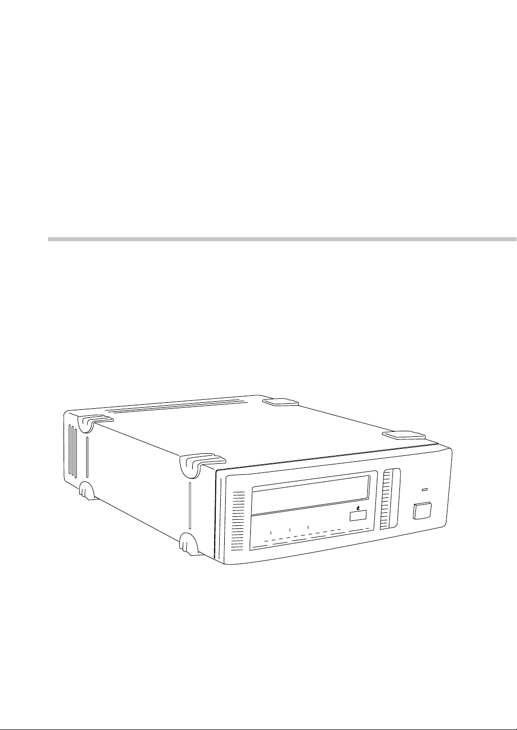
This Guide describes the AIT Drive Unit SDX-D500C / D400C, and how to
take care of it. Please read it carefully before using the unit, and keep it handy
for future reference.
The Guide consists of four parts, plus the specifications. Refer to the parts
that relate to your use of the drive.
Part 1 describes the features of the drive, its system components, and the
name and function of each part.
Part 2 describes the necessary connections between the drive and the host
computer. If other SCSI devices are being used, you may need to change the
SCSI ID setting. Read this part if you are installing the drive.
Part 3 describes how to use the drive, including how to turn it on, and how to
insert and remove cartridges. Read this part if you are going to operate the
drive.
Part 4 describes how to take care of the drive and cartridges, and how to
clean the drive heads. Read this part before using the drive.
The Specifications appendix provides the major specifications of the SDXD500C / D400C.
5

Part 1. Introduction
About AIT Drives
The SDX-D500C is an external AIT drive unit that uses data cartridges
conforming to the AIT-2 format. The SDX-D400C is an external AIT drive
unit that uses data cartridges conforming to the AIT-1 format. The SDXD500C supports AIT-1 and AIT-2 formats. The SDX-D400C supports only
AIT-1 format.
Features
The AIT Drive Unit SDX-D500C has the following features:
• The Advanced Intelligent Tape format provides a huge data storage
capacity on AIT-1/AIT-2 data cartridges.
• Read After Write Function and third-level error correction code guarantee
high data reliability.
• Data compression provides 100 gigabytes of storage on 230 m tape-length
cartridge.
The native capacity is 50 gigabytes of storage on 230 m tape-length
cartridge.
• Stored data are automatically checked for compression.
• Ultra Wide LVD/SE SCSI interface is fully supported for host computer
access.
• Read/Write operation is available with AIT-1 and AIT-2 formats.
*1
Part 1. Introduction
6
*1
This is assuming 2 : 1 compression ratio.
The degree of data compression attained while recording data varies according to
system environment and data type.

The AIT Drive Unit SDX-D400C has the following features:
• The Advanced Intelligent Tape format provides a huge data storage
capacity on AIT-1 data cartridges.
• Read After Write Function and third-level error correction code guarantee
high data reliability.
• Data compression provides 70 gigabytes of storage on 230 m tape-length
cartridge.
*1
The native capacity is 35 gigabytes of storage on 230 m tape-length
cartridge.
• Stored data are automatically checked for compression.
• Ultra Wide LVD/SE SCSI interface is fully supported for host computer
access.
• Read/Write operation is available with AIT-1 format.
*1
This is assuming 2 : 1 compression ratio.
The degree of data compression attained while recording data varies according to
system environment and data type.
Part 1. Introduction
7
Useable Cartridges
Data cartridges used with the SDX-D400C must be marked with the AIT-1,
logo. The SDX-D500C can be used with data cartridges marked with AIT-1
or AIT-2 logo.
CAUTION:
Be sure to use only the cartridges designed specifically for AIT (do not use
8 mm cartridges for video).
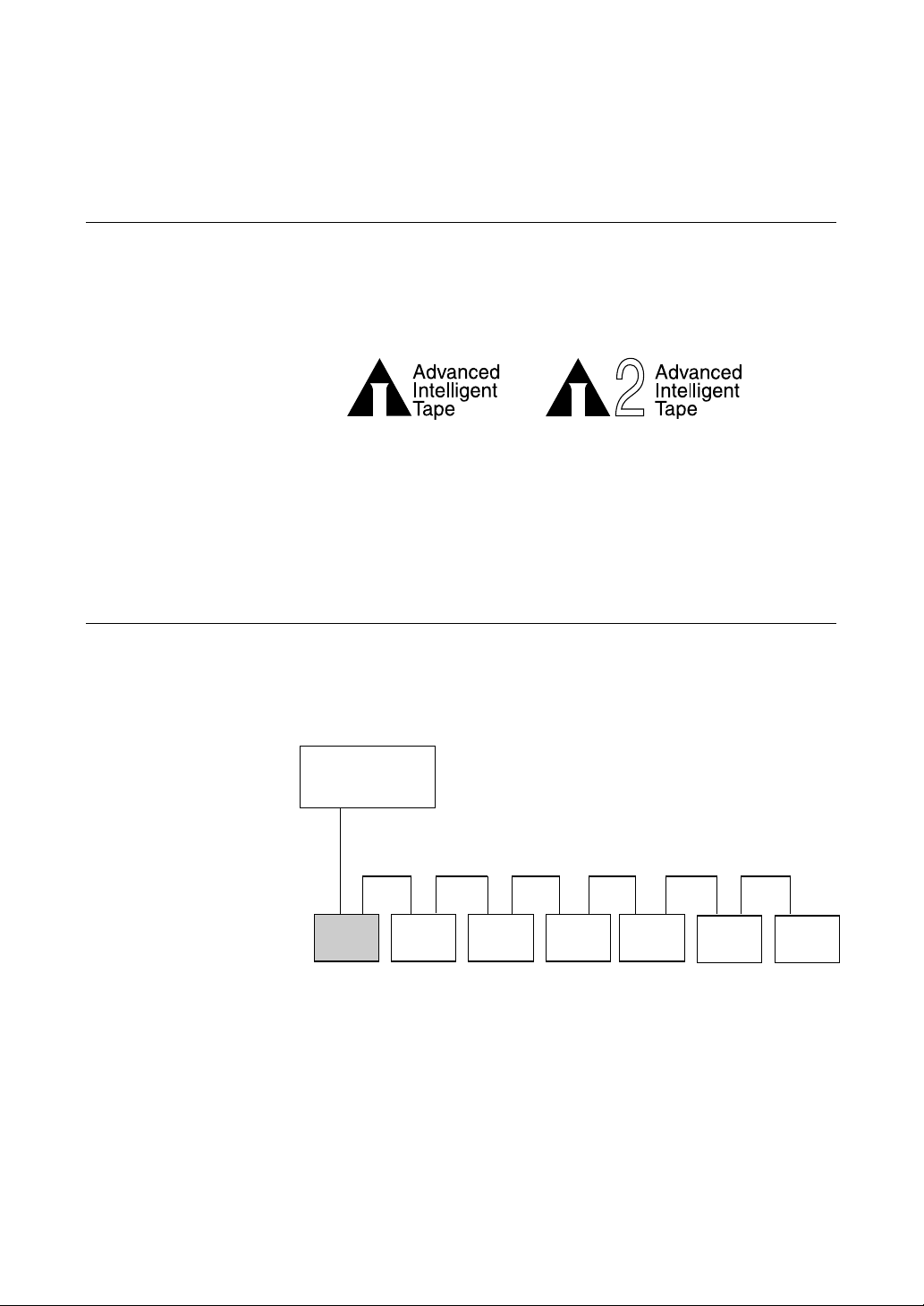
System Components
The SDX-D500C / D400C connects to the host computer via a Ultra Wide
LVD/SE SCSI interface.
AIT-1 LOGO AIT-2 LOGO
Part 1. Introduction
8
Host Computer
SDX-D500C / D400C
Figure 1-1. Example of System Components
Peripheral Devices

Part Names and Functions
Front panel
1
2
POWER
3 4 5
Figure 1-2. Front panel
6
1 AIT Data Cartridge Receptacle
See page 14 for information on inserting and removing a AIT data
cartridge.
2 POWER Indicator
Lights while the drive is on.
3 BUSY Indicator
Lights when data is being transferred through the SCSI interface. This
indicator also lights under the following conditions:
Drive is reading or writing repeated blinking (same on-off
normally: interval).
4 TAPE Indicator
When a AIT cartridge is installed, this indicator lights. This also lights
under the following conditions:
Inserting and removing repeated blinking (same on-off
a cartridge: interval).
Cartridge deteriorated: alternating long-short blinking.
7
Part 1. Introduction
9

5 STATUS Indicator
Lights when an inserted cartridge is write-protected. This indicator also
lights under the following conditions:
Drive needs cleaning: repeating long-on, short-off
blinking.
End of Tape during cleaning: repeating blinking (same on-off
interval).
Drive Malfunctioning: repeating short-on (once or twice),
long-off blinking.
6 EJECT Button
Push to remove a data cartridge from the drive.
7 POWER Switch
Press to turn the drive on or off.
Part 1. Introduction
10
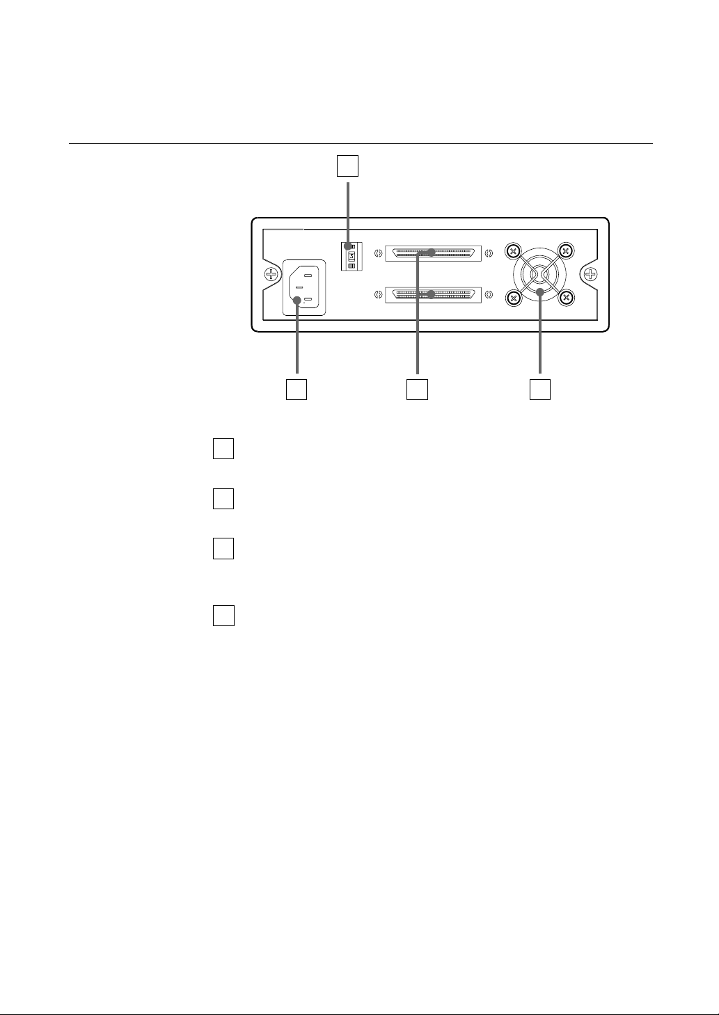
Rear Panel
1
2
3 4
Figure 1-3. Rear Panel
1 Rotary Selector Switch
SCSI ID selector.
2 AC IN Connector
Connect the supplied power cable here.
3 SCSI Connector
Connects to the SCSI bus connector of the host computer or another
SCSI peripheral.
4 Cooling Fan
Part 1. Introduction
11
Part 2. Preparation
After you confirm that you have all of the required accessories for your
installation, connect the drive to the host computer, and select the SCSI ID
with the rotary switch on the rear panel.
Supplied Items
When you first open the box, make sure it contains the following items.
Contact your supplier if anything is missing or broken.
• AIT Drive Unit
• Power Cable
• Operator's Guide
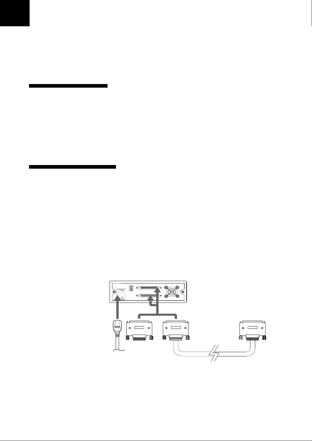
Interconnections
The SCSI bus allows connection of up to fifteen peripherals to the host
computer. Use a SCSI cable with a half pitch 68 pin connector.
Precautions
• Switch off the host computer and peripherals before connecting the SCSI
cable.
• Make sure the SCSI connectors are pressed tightly together.
• If this unit is the last (or only) device on the SCSI bus, make sure to connect
a SCSI bus terminator to the open connector.
• The total length of the SCSI cable(s) between the host computer and the last
device should be less than 12 meters.
AC power
Figure 2-1 Interconnections
*1
It should be less than 1.5 meters, if connected to single-ended SCSI host adaptor.
*1
Part 2. Preparation
12
SCSI ID Setting
The SCSI ID is set by the rotary switch on the rear panel. Press the + or buttons to move the number up or down, respectively.
As shipped from the factory, the SCSI ID is set to 0. Press the switch buttons,
if necessary, to select the SCSI ID number you require.
Precautions
• The SCSI ID must be different from IDs of the other peripherals on the SCSI
bus.
• As shipped from the factory, SCSI parity is enabled and Term power is ON.
A SCSI bus terminator must be connected to the SCSI bus before use.
• Before changing the SCSI ID setting, be sure to turn off the power with the
POWER switch on the front panel.
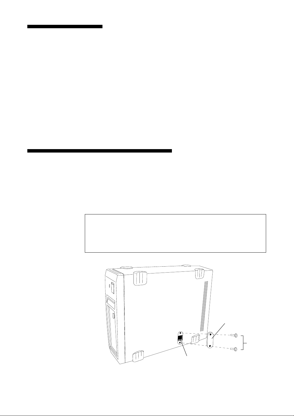
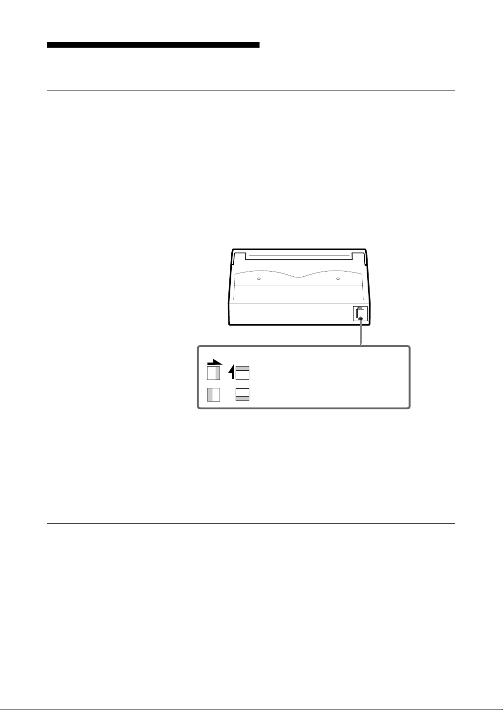
Option Switches (DIP Switch)
Remove the two slotted screws by using a slotted screwdriver. Remove the
access cover to change the DIP switch settings. (Refer to the following
figure for details changing the DIP switch settings.)
After changing the DIP switch settings, replace access cover and tighten the
two slotted screws using a slotted screwdriver.
CAUTION
Before removing the access cover to change DIP switch settings on the drive,
turn off the computer and disconnect the power cord from the unit. Once the
DIP switch settings have been changed, replace the access cover using the
two original slotted screws provided.
Access Cover
Slotted
Screws
DIP Switch
Part 2. Preparation
13

DIP Switch Positions
1 Reserved (OFF)
2 Reserved (OFF)
3 Reserved (OFF)
4 Reserved (OFF)
5 Terminator Power (ON)
6 Reserved (OFF)
7 DC Control (1) (ON)
8 DC Control (2) (OFF)
Data Compression Control DIP Switch
Data compression can be selected by DIP switches. Data compression is
enabled while position 7 [DC Control (1)] is ON. Control by host can be
disabled when position 8 [DC Control (2)] is ON.
Part 2. Preparation
14
Part 3. Operation
This section describes how to use the AIT drive, and how to handle data
cartridges.
How to use the AIT Drive
1 Press the POWER switch on the front panel.
The POWER indicator should light, and the STATUS, BUSY and TAPE
indicators should blink as the self-test is performed.
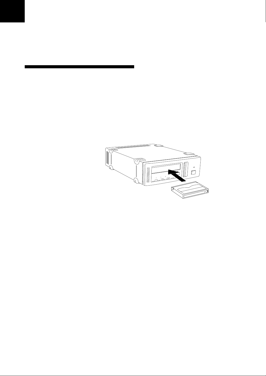
2 When the three indicators stop blinking, you can insert a data cartridge
as shown below. The TAPE indicator will blink, and if the cartridge is
write-protected, the STATUS indicator will light.
Figure 3-1. Inserting a data cartridge
3 Computer software controls the reading and writing of tapes. While
reading or writing, the BUSY indicator blinks.
Part 3. Operation
15
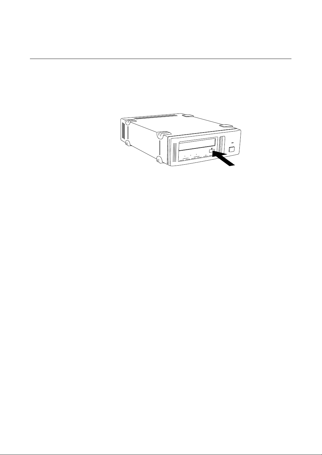
Cartridge Removal
Press the EJECT button.
The cartridge ejects automatically.
Figure 3-2. Press the EJECT button
Caution
Do not push the EJECT button while the BUSY indicator is blinking: to do so
may destroy data on the tape.
Part 3. Operation
16

Part 4. Care and Maintenance
Taking Care of the Drive
Safety Considerations
■ Power
• Be sure to use only 100-240 V AC.
• Avoid plugging into the same outlet as high-current equipment like copiers
or shredders.
■ Power Cable Precautions
• Do not crush the cable or place heavy items on it. If the cable insulation
appears worn or broken, do not use the cable.
• Always unplug the cable by holding the plug: never pull the cable itself, as it
will break.
• If the drive is not being used for a long time, unplug the cable from the
outlet.
Avoiding Damage
■ Avoid shock and vibration
Intense shock, such as from dropping the drive, will damage it.
■ Environmental considerations
Do not store or use the drive in locations subject to:
• high humidity • excessive dust
• high temperature • intense vibration
• direct sunlight • sudden changes in temperature
■ Proper ventilation
To avoid overheating, install the drive where it will have free air circulation
around the case, and do not cover it during operation. The drive can
malfunction if the internal temperature rises too high.
■ Avoid sudden changes in temperature
If the drive is moved from a cool place to a warm place, or if the room
temperature suddenly rises, moisture may condense inside the case. After a
sudden change in temperature, wait at least one hour before turning the drive
on. If the drive is turned on with condensation inside, and a cartridge is
installed, the drive or the tape can be damaged.
Part 4. Care and Maintenance
17

■ Abnormal occurrences
If the drive behaves abnormally, or if it begins to smell or smoke, immediately
unplug it from the wall outlet and contact your supplier for assistance.
■ Cabinet cleaning
Wipe the cabinet with a soft dry cloth. For heavy dirt, wipe with a soft cloth
moistened with a gentle liquid soap, then wipe again with a soft dry cloth. Do
not use alcohol, paint thinner, bug sprays or other volatile solvents, as they
can damage the finish.
Part 4. Care and Maintenance
18
Taking Care of Cartridges
Use Precautions
• Avoid heavy vibration and dropping.
• The shutter on the face of the cartridge is opened automatically when it is
inserted into the drive. Do not open the shutter by hand, as touching the
tape may damage it.
• The cartridge was carefully aligned during assembly at the factory. Please do
not try to open it or take it apart.
• The write-protect switch on the face of the cartridge prevents the tape from
being written to or accidentally erased. If you do not need to write to the
tape, move this switch to the write-protect position (in the direction of the
arrow).
• In case of a sudden change in temperature, condensation may interfere with
• Avoid unnecessary insertion and removal of cartridges if you do not need to
• When finished using the drive, remove the cartridge.
Storage Precautions
• Keep cartridges in their cases when not in the drive.
• Avoid storing cartridges in dusty places, in direct sunlight, near heaters or
• Do not place cartridges on the dashboard or in a storage tray in a car.
AIT-1 AIT-2
Using your fingernail, push the switch in the
direction of the arrow to protect the tape from
writing or accidental erasure.
Return the switch to its original position to
re-enable writing.
Figure 4-1. Write-protect switch
reading and writing to a tape.
write or read a tape.
air conditioners, or in humid locations.
Part 4. Care and Maintenance
19

Head Cleaning
To keep the AIT drive in top condition, clean the head as needed, using the
proper head cleaning cartridge (sold separately). When the head needs
cleaning, the STATUS indicator will blink.
How to Clean
1 Load the head cleaning cartridge (SDX1-CL) into the AIT drive.
2 After about 15 seconds, cleaning will stop and the cartridge will eject
Notice:
Do not rewind the cleaning cartridge and reuse it. When you reach the end of
the cartridge, dispose it and buy a new one.
Cleaning starts automatically.
automatically.
One head cleaning cartridge can be used about 30 times.
Part 4. Care and Maintenance
20

Appendix
Specifications (SDX-D500C)
■ Performance
Storage Capacity 100 GB compressed
Bit Error Rate less than 10
Data Transfer Rate 6 MB/s uncompressed
(TAPE) 12 MB/s compressed
Burst Data Transfer Rate 12 MB/s maximum, asynchronous
(SCSI) 40 MB/s maximum, synchronous
Initialize Time less than 5 seconds
Load Time less than24 seconds
Unload Time less than 30 seconds
Rewind Time less than 105 seconds (with 230 m tape)
■ Operating Environment
Operating Temperature: 10 to 35 °C
Non-Operating Temperature: -40 to +70 °C
(with 230 m AIT-2 tape)
50 GB uncompressed
(with 230 m AIT-2 tape)
-17
Humidity: 30 t o 80%
Maximum wet bulb temperature: 26 °C
Humidity: 10 to 9 0%
*1
(no condensation)
■ Power Supply & Miscellaneous
Power Supply 100-240 V AC, 50/60 Hz
Case Dimensions 198 x 64.5 x 246 mm (W x H x D)
Weight 2.4 kg
Accessories Power Cable (1)
Specifications may be subject to change, in the interest of technological
improvement, without notice or obligation.
*1
This is assuming 2 : 1 compression ratio.
The degree of data compression attained while recording data varies according to
system environment and data type.
1.2 A
(excluding protruding parts)
Operator's Guide (1)
Appendix
21

Specifications (SDX-D400C)
■ Performance
Storage Capacity 70 GB compressed
Bit Error Rate less than 10
Data Transfer Rate 4 MB/s uncompressed
(TAPE) 8 MB/s compressed
Burst Data Transfer Rate 12 MB/s maximum, asynchronous
(SCSI) 40 MB/s maximum, synchronous
Initialize Time less than 5 seconds
Load Time less than 24 seconds
Unload Time less than 30 seconds
Rewind Time less than 105 seconds (with 230 m tape)
■ Operating Environment
Operating Temperature: 10 to 35 °C
Non-Operating Temperature: -40 to +70 °C
(with 230 m AIT-1 tape)
*1
35 GB uncompressed
(with 230 m AIT-1 tape)
-17
Humidity: 30 t o 80%
(no condensation)
Maximum wet bulb temperature: 26 °C
Humidity: 10 to 9 0%
■ Power Supply & Miscellaneous
Power Supply 100-240 V AC, 50/60 Hz
Case Dimensions 198 x 64.5 x 246 mm (W x H x D)
Weight 2.4 kg
Accessories Power Cable (1)
Specifications may be subject to change, in the interest of technological
improvement, without notice or obligation.
*1
This is assuming 2 : 1 compression ratio.
The degree of data compression attained while recording data varies according to
system environment and data type.
Appendix
22
1.2 A
(excluding protruding parts)
Operator's Guide (1)

SDX-D500C / D400C
Lecteur AIT
4-651-451-01
Manuel de l’Utilisateur

Règles de sécurité
Informations spécifiques de l’utilisateur
Les numéros du modèle et de série sont situés sous l’appareil. Inscrivez les
numéros de série dans l’espace prévu ci dessous
Reférez vous y chaque fois que vous appelez votre revendeur Sony à propos
de ce matériel
No de modèle No de série
Informations
AVERTISSEMENT
Afin éviter tout risque d’incendie ou d’électrocution,
ne pas exposer cet appareil à la pluie ou à l’humidité.
Pour éviter une électrocution,ne tentez pas d’ouvrir le
module.
Confier l’entretien à un spécialiste uniquement.
Aux utilisateurs vivant aux U.S.A.
Veuillez noter que tout changement ou modification apportés, non
expressément autorisés dans ce manuel pourraient vous priver de votre droit
d’utilisation de ce matériel.
AVERTISSEMENT
Remarque: Ce matériel après tests satisfait aux normes des équipements
digitaux de la classe B, conformément au chapitre 15 de la réglementation
de la FCC. Ces normes ont pour objet d’assurer une protection raisonnable
contre des interférences parasites dans une installation domestique. Ce
matériel produit, utilise et peut émettre des ondes-radio. Il peut donc
parasiter des communications radio s’il n’est pas installé et utilisé selon les
instructions. Cependant il n’y a aucune garantie que ces interférences ne
puissent se produire au sein d’une installation domestique. Si cet
équipement venait à parasiter la réception des émissions de radio ou de
télévision, ce qui peut être déterminé en allumant puis en éteignant le
module, l’utilisateur est encouragé à essayer de corriger ces interférences en
respectant les mesures suivantes.
• Orienter différemment ou déplacer l’antenne réceptrice
• Eloigner davantage le module de l’appareil récepteur.
• Brancher le module sur une prise reliée à un circuit différent de celui
de l’appareil récepteur.
• Si besoin, prenez conseil auprès de votre distributeur ou d’un
technicien radio/TV expérimenté.
24

NOTIFICATION
CETTE NOTIFICATION EST VALABLE AUX U.S.A ET CANADA
UNIQUEMENT
Pour les U.S.A, utiliser le cordon-secteur 220-240V type UL décrit ci-dessous
Pour le CANADA, utiliser le cordon-secteur 220-240V certifié CSA, décrit ci-
dessous
N’UTILISER AUCUN AUTRE CORDON D’ALIMENTATION.
Branchement Prise bi-polaire avec mise à la terre
(Configuration NEMA 6-15P)
Cordon Type SVT ou SJT, trois fils AWG de section 16 ou 18.
Longueur Maximum 14.7 feet (4.5m)
Valeur Minimale 10A, 250 V
NOTIFICAT ION
La notification qui suit est valable pour les pays autres que les U.S.A et le Canada.
Dans les pays autres que les U.S.A et le Canada, utiliser le cordon-secteur
approuvé par les organismes ayant autorité dans chacun des pays
concernés.
25

Sommaire
Mode d'emploi de ce guide 27
1. Introduction 28
A propos des lecteurs AIT 28
Caractéristiques ............................................................................................28
Cartouches Utilisables ..................................................................................30
Composants du Système ..............................................................................30
Identification et Fonction des Pièces 31
Panneau avant ..............................................................................................31
Panneau arrière ............................................................................................33
2. Préparation 34
Accessoires Fournis 34
Interconnections 34
Configuration de l’identification SCSI 35
Commutateurs d’option (commutateur DIP) 35
English
3. Fonctionnement 37
Mode d’emploi du lecteur AIT 37
Retirer la cartouche .......................................................................................38
4. Soins et Entretien 39
Soins à apporter au lecteur 39
Pensez à la sécurité ......................................................................................39
Eviter des Dommages ................................................................................... 39
Soins à apporter aux cartouches 41
Précautions d’utilisation ................................................................................41
Précautions pour l’entreposage.................................................................... 41
Nettoyage des têtes de lecture 42
Comment nettoyer ......................................................................................... 42
Annexe 43
Caractéristiques techniques (SDX-D500C) 43
Caractéristiques techniques (SDX-D400C) 44
26

Mode d'emploi de ce guide
Ce guide a pour objet de décrire le lecteur AIT SDX-D500C/D400C et
d’expliquer comment en prendre soin. Lisez-le s’il vous plaît attentivement
avant d’utiliser le lecteur et garder le à portée de main pour pouvoir le
consulter ultérieurement.
Ce guide est composé de quatre parties, plus les caractéristiques techniques
en annexe. Référez-vous aux chapitres en fonction de l’usage que vous avez
de ce lecteur.
Partie 1 décrit les caractéristiques du lecteur, les composants du système et
donne le nom et la fonction de chacune des pièces qui le composent.
Partie 2 décrit les connections nécessaires entre le lecteur et l’ordinateur
principal. Si d’autres périphériques sont utilisés, il vous faudra peut-être
modifier la configuration d’identification SCSI A lire si vous êtes en train
d’installer le lecteur.
Partie 3 explique comment utiliser le lecteur, comment l’allumer et
comment insérer et retirer des cartouches A lire si vous êtes sur le point de
faire fonctionner le lecteur.
Partie 4 explique comment prendre soin.du lecteur et des cartouches et
comment nettoyer les têtes de lecture. A lire avant d’utiliser le lecteur.
Les Spécifications en Annexe traitent des principales caractéristiques
techniques du SDX-D500C/D400C.
27
 Loading...