

Sony SDX-900V, SDX-900V/R Product Specifications

SDX-900V
SDX-900V/R
5.25”Model
Product Specification Manual
Version 2.1
July 2005
Copyright © 2004-2005, Sony Corporation.
All right reserved.
NOTE:
This Product Specification Manual is applicable for AIT-4 drive.

Notice
This document contains proprietary information which is protected by copyright. All rights reserved. No part of this
document may be photocopied, reproduced or translated to another language without prior written consent of
Sony. The information contained in this document is subject to change without notice.
SONY MAKES NO WARRANTY OF ANY KIND WITH REGARD TO THIS DOCUMENT. Sony shall not be liable
for errors contained herein, or indirect, special, incidental or consequential damages in connection with the
furnishing, performance, or use of this document.
© Copyright 2004-2005, Sony Corporation
For further information, please contact the appropriate Sony location listed below;
Japan
Korea
Sony Corporation
Micro System Network Company
Applications & Devices Marketing Group
Atsugi Tec.
4-14-1 Asahi-cho Atsugi-shi,Kanagawa,
243-0014 Japan
TEL: (81) 46-202-8287 FAX: (81) 46-230-6346
Sony Korea Corporation.
B&P Group Product Marketing Team B2B
Marketing Part.
34F, ASEM Tower, World Trade Center, 159-1
Samsung-Dong, Kangnam-Ku, Seoul, 135-798 Korea
TEL: 82-2-6001-4249
U.S.A
Taiwan
Sony Electronics Inc.
3300 Zanker Road, MS SJ3F5, San Jose, California
95134-1901, U.S.A.
TEL: (1) 408-432-1600
Sony Taiwan Limited.
Applications & Devices Marketing Taiwan
Company Sales & Marketing Dept.
5F, 145 Changchun Road, Taipei 104, Taiwan
TEL: (886) 2-2522-7953 FAX: (886) 2-2522-2153
Europe
Hong Kong
Sony Europe Semiconductor &
Electronic Solutions
The Heights, Blooklands, Weybridge, Surrey KT13
OXW,UK
TEL: (01932) 81-6000
Sony Corp. of Hong Kong Ltd. Hong Kong Office
Electronic Devices Marketing Hong Kong
45F The Lee Gardens 33 Hysan Avenue,
Causeway Bay,Hong Kong
TEL: 852-2909-1008 FAX: 852-2909-2001
Canada
Brazil
Sony of Canada Ltd.
Broadcast & Communication Solutions Division,
Storage Solutions Marketing
115 Gordon Baker Road Toronto,
Ontario CANADA M2H 3R6
TEL: (1)416- 499-1414 FAX: (1)416-495-3722
Sony Basil Ltda.
Rua Inocencio Tobias,125,Barra Funda,CEP
01144-000 Sao Paulo, SP Brasil
TEL: (55) 11-3613-9000 FAX: (55) 11-3611-9064
Singapore South Asia & Africa
Applications &Devices Marketing(Singapore)
A division company of Sony Electronics(S)
Pte.Ltd.
Enterprise Storage Solutions Dept.
2 International Business Park #01-10 Tower One,
The Strategy Singapore 609930
TEL: +65 6544 8000 FAX: +65 6544 7394
Changing List
Page Clause Title Modify Add Delete Remarks
SDX-900V, SDX-900V/R Ver. 1.0 JULY, 2004 (RELEASE)
SDX-900V, SDX-900V/R Ver. 1.1 SEPTEMBER, 2004 (From Ver. 1.0 To 1.1)
4-3 4.3.3. Power-Fail or SCSI Reset Handing *
6-24 6.6.7. Tape Log Page (Sony Unique) *
Table 6-22
6-25 6.6.8. Tape Capacity Log Page (Sony Unique) *
Table 6-24
6-26 6.6.9. Drive Usage Log Page (Sony Unique) *
Table 6-26
6-32 6.6.12. AIT Log Page (Sony Unique) *
Parameter Code:
6-37 6.6.13. MIC Fixed Length Information Page
(Sony Unique)
*
89 → 93
6-73 6.13. READ ATTRIBUTE 8Ch *
Table 6-64
6-77 6.14. READ BLOCK LIMITS 05h *
Table 6-70
6-88 6.19. REPORT DENSITY SUPPORT 44h
*
Table 6-85
6-90 6.20. REPORT DEVICE IDENTIFIER A3h *
• 2-3, 4-5 → 2-5
• Table 6-86
6-94 6.22. REQUEST SENSE 03h *
Table 6-90
6-95 6.22. REQUEST SENSE 03h *
Table 6-91
6-100 6.23. RESERVE UNIT (6/10) 16h and 56h
*
Table 6-93
6-104 6.25. SEND DIAGNOSTIC 1Dh *
0 = Continuous
→ 1 = run once
6-105 6.26. SET DEVICE IDENTIFIER A4h
*
2, 3, 4-5 → 2-5
7-3 7.2.3. SEND DIAGNOSTIC command-Individual
Test
*
0 = Continuous
→ 0 = run once
7-4 7.2.4. Diagnostic Test Number Summary *
Drive Test
7-7 7.2.7. Diagnostic Tests requiring additional
parameters
*
7-7 7.2.7.1. Read Data Exerciser (43h) Diagnostic
Parameters
*
8-1 8. APPENDIX A: ASC & ASCQ Alphabetic
Order
*
9-1 9. APPENDIX B: ASC & ASCQ Numeric
Order
*
12-1 12. APPENDIX E: Medium Auxiliary Memory
Attribute
*
13-1 13.
APPENDIX F: AIT based WORM system
*
APPENDIX E →
F
14-1 14.
APPENDIX G: DISASTER RECOVER
*
APPENDIX F →
G
15-1 15.
APPENDIX H: GLOSSARY
*
APPENDIX G →
H
SDX-900V, SDX-900V/R Ver. 2.0 APRIL, 2005 (From Ver. 1.1 To 2.0)
1-1 1.3. Features of the Drive *
1-2 1.3. Features of the Drive *
1-3 1.4. Reference *
2-6 2.3. Performance Specification *
2-6 2.3.1. Data Capacity *
2-7 2.3.2.1. Sustained Data Transfer Rate to and from
the Tape
*
2-7 2.3.4. Load Time *
2-7 2.3.5. Unload Time *
2-7 2.3.6. Search Time *
2-7 2.3.7. Rewind Time *
2-8 2.3.9. Retry Limits on Rewrites *
2-10 2.6. Data Compression *
Page Clause Title Modify
Add Delete Remarks
4-2 4.2.5. Write-Protecting Cassettes *
4-3 4.3.1. The Load Sequence (Effective for non
MIC cassette, only) Refer to 12.2.1. Fast
Media Load/Unload (Effective for MIC
cassette, only)
*
AIT-1 → AIT-4
4-5 4.5. Tape Format *
4-6 4.5.1. Tape Partition
*
4-7 4.6.1.3. Usage of Cleaning Cassette *
6-10 6.4. LOCATE 2Bh *
6-12 6.5.
LOG SELECT 4Ch
*
6-25 6.6.8. Tape Capacity Log Page (Sony Unique) *
Table 6-24
6-26 6.6.9. Drive Usage Log Page (Sony Unique) *
Table 6-26
6-27 6.6.9. Drive Usage Log Page (Sony Unique) *
Table 6-28
6-28 6.6.10. Read and Write Frame Error Counter
Page
*
6-30 6.6.12. AIT Log Page (Sony Unique) *
6-31 6.6.12. AIT Log Page (Sony Unique) *
6-32 6.6.12. AIT Log Page (Sony Unique) *
6-33 6.6.13. MIC Fixed Length Information Page
(Sony Unique)
*
6-34 6.6.13. MIC Fixed Length Information Page
(Sony Unique)
*
6-38 6.6.13. MIC Fixed Length Information Page
(Sony Unique)
*
6-39 6.6.14. MIC Variable Length Information Page
(Sony Unique)
*
6-40 6.6.14. MIC Variable Length Information Page
(Sony Unique)
*
6-43 6.7. MODE SELECT (6/10) 15h and 55h *
Table 6-39
6-49 6.7.5. Medium Partitions Parameter Page (11h) *
6-50 6.7.5. Medium Partitions Parameter Page (11h) *
6-51 6.7.5. Medium Partitions Parameter Page (11h) *
6-51 6.7.6. Medium Partitions Parameter Page
(for multi-partitioned tapes) (11h)
*
6-55 6.7.8. AIT Device Configuration Page (31h) *
6-56 6.7.8. AIT Device Configuration Page (31h) *
6-57 6.7.9. Append Partition (32h) *
6-59 6.7.10. Delete Partition (33h) *
6-63 6.8. MODE SENSE (6/10) 1Ah and 5Ah *
Table 6-53
6-72 6.12. READ 08h *
6-74 6.13.1. ATTRIBUTE VALUES service action *
table 6-70
→table 6-65
6-76 6.13.3 PARTITION LIST service action *
table 12.0
→table 6-67
6-88 6.19. REPORT DENSITY SUPPORT 44h *
Table 6-85
6-96 6.22. REQUEST SENSE 03h
Table 6-91
6-97 6.22. REQUEST SENSE 03h *
Table 6-91
6-105 6.26. SET DEVICE IDENTIFIER A4h *
6-111 6.30. WRITE ATTRIBUTE 8Dh *
table 6-109
→table 6-100
6-112 6.30. WRITE ATTRIBUTE 8Dh *
table 6-106
→table 6-101
7-6 7.2.6. Diagnostics Results Reference *
7-7 7.2.6. Diagnostics Results Reference *
Page Clause Title Modify
Add Delete Remarks
13-1 13.3. How to detect a WORM cartridge.
(AIT2 WORM Media: SDX2-50W, AIT3
WORM Media: SDX3-100W)
*
13-4 13.5. How to handle the WORM cartridge in the
drive.
*
15-1 15. APPENDIX H: GLOSSARY *
15-2 15. APPENDIX H: GLOSSARY *
15-3 15. APPENDIX H: GLOSSARY *
SDX-900V, SDX-900V/R Ver. 2.1 July, 2005 (From Ver. 2.0 To 2.1)
6-91 6.22. REQUEST SENSE 03h *
Table 6-90
13-1 13.1 Important Notice *
0200 → 0103

This page intentionally left blank.

SDX-900V series Ver.2.1 Table of Contents
Table of Contents
1. Introduction
1.1. About this Product Specification Manual 1- 1
1.2. Introducing the SONY AIT Technology 1- 1
1.3. Features of the Drive 1- 1
1.4. Reference 1- 3
1.4.1. How to get ECMA-222, 246, 291, 292, 329 Standard Document 1- 3
2. Specifications
2.1. Specifications 2- 1
2.1.1. Dimensions 2- 1
2.1.1.1. Mounting Holes 2- 2
2.1.2. Weight 2- 4
2.1.3. Connectors 2- 4
2.1.3.1. SCSI Cables and Terminators 2- 4
2.2. Environmental Specifications 2- 4
2.2.1. Temperature and Humidity Range 2- 4
2.2.2. Altitude 2- 5
2.2.3. Suspended Particulate 2- 5
2.2.4. Vibration 2- 5
2.2.5. Shock 2- 5
2.2.6. Acoustic Noise 2- 5
2.2.7. EMC 2- 5
2.2.8. Orientation 2- 5
2.3. Performance Specification 2- 6
2.3.1. Data Capacity 2- 6
2.3.2. Data Transfer Rate 2- 7
2.3.2.1. Sustained Data Transfer Rate to and from the Tape 2- 7
2.3.2.2. Burst Transfer Rate to and from the SCSI Bus 2- 7
2.3.3. Initialize Time 2- 7
2.3.4. Load Time 2- 7
2.3.5. Unload Time 2- 7
2.3.6. Search Time 2- 7
2.3.7. Rewind Time 2- 7
2.3.8. Error Rate 2- 8
2.3.9. Retry Limits on Rewrites 2- 8
2.3.10. Definition of Failure 2- 8
2.3.11. Mean Time Between Failures 2- 8
2.3.12. Mean Time to Repair 2- 8
2.3.13. Component Life 2- 8
2.3.14. Durability 2- 8
2.4. Safety 2- 9
2.4.1. Conditions of Acceptability 2- 9
2.5. Installation Requirements 2- 9
2.5.1. Power Requirements 2- 9
2.6. Data Compression 2- 10

SDX-900V series Ver.2.1 Table of Contents
3. Installation
3.1. Installation Guide 3- 1
3.1.1. SCSI ID Number Jumper 3- 2
3.1.2. Termination Power Switch 3- 2
3.1.3. Parity Disable Jumper 3- 3
3.1.4. Data Compression ON Switch 3- 3
3.1.5. Power Connector 3- 3
3.1.6. SCSI 68 pin Connector 3- 3
3.1.7. Attaching and Removing the Dust Cover 3- 6
3.1.7.1. Attaching the Dust Cover 3- 6
3.1.7.2. Removing the Dust Cover 3- 7
4. Operation
4.1. Summary of LED Indications 4- 1
4.2. Operator Action 4- 2
4.2.1. Powering up the SDX-900V 4- 2
4.2.2. Inserting Cassettes 4- 2
4.2.3. Removing Cassettes 4- 2
4.2.4. Hard Reset Hole 4- 2
4.2.5. Write-Protecting Cassettes 4- 2
4.3. Internal Function 4- 3
4.3.1. The Load Sequence
(Effective for non MIC cassette, only) Refer to 12.2.1. Fast
Media Load/Unload (Effective for MIC cassette, only)
4- 3
4.3.2. The Unload Sequence
(Effective for non MIC cassette, only) Refer to 12.2.1. Fast
Media Load/Unload (Effective for MIC cassette, only)
4- 3
4.3.3. Power-Fail or SCSI Reset Handling 4- 3
4.3.4. Diagnostic and Normal Status Displays 4- 4
4.3.4.1. Diagnostic Status Display 4- 4
4.3.4.2. Normal Status Display 4- 4
4.4. Tape Alert 4- 5
4.5. Tape Format 4- 5
4.6. Maintenance, Troubleshooting and Service 4- 6
4.6.1. Head Cleaning 4- 6
4.6.1.1. Message when cleaning cassette is necessary 4- 6
4.6.1.2. The Condition of Cleaning Request 4- 6
4.6.1.3. Usage of cleaning cassette 4- 6
4.6.2. Troubleshooting Guide 4- 6
4.6.2.1. Operational Problems 4- 6
4.6.2.2. Read/Write Problems 4- 9
4.6.2.3 Replace Tape 4- 9
4.6.2.4. Media Warning 4- 9
4.6.3. Clearance for Service 4- 9
4.6.4. Packaging for Return to Sony 4- 9

SDX-900V series Ver.2.1 Table of Contents
5. SCSI Interface
5.1. Introduction 5- 1
5.1.1. Overview of the SCSI Interface 5- 1
5.1.2. Supported Messages 5- 1
5.1.3. Supported Commands 5- 2
5.2. SCSI BUS Operation 5- 3
5.2.1. Typical SCSI Operation 5- 3
5.2.2. Disconnect 5- 3
5.3. Message Specification 5- 4
5.3.1. COMMAND COMPLETE (00h) 5- 5
5.3.2. EXTENDED MESSAGE (01h) 5- 5
5.3.2.1. PARALLEL PROTOCOL REQUEST (04h) 5- 5
5.3.2.2. SYNCHRONOUS DATA TRANSFER REQUEST (01h) 5- 6
5.3.2.3. WIDE DATA TRANSFER REQUEST 5- 8
5.3.3. SAVE DATA POINTER (02h) 5- 9
5.3.4. RESTORE POINTERS (03h) 5- 9
5.3.5. DISCONNECT (04h) 5- 9
5.3.6. INITIATOR DETECTED ERROR (05h) 5- 10
5.3.7. ABORT (06h) 5- 10
5.3.8. MESSAGE REJECT (07h) 5- 10
5.3.9. NO OPERATION (08h) 5- 10
5.3.10. MESSAGE PARITY ERROR (09h) 5- 10
5.3.11. BUS DEVICE RESET (0Ch) 5- 11
5.3.12. IDENTIFY (80h-FFh) 5- 11
5.3.13. IGNORE WIDE RESIDUE (23h) 5- 11
5.4. Status Specification 5- 12
6. Command Specification
6.1. ERASE 19h 6- 2
6.2. INQUIRY 12h 6- 3
6.3. LOAD/UNLOAD 1Bh 6- 8
6.4. LOCATE 2Bh 6- 10
6.5. LOG SELECT 4Ch 6- 11
6.6. LOG SENSE 4Dh 6- 13
6.6.1. The Log Page Descriptor 6- 14
6.6.2. The Log Parameter Descriptor 6- 15
6.6.3. Supported Log Pages 6- 16
6.6.3.1. Summary List of Supported Pages 6- 17
6.6.4. Write and Read Error Counters Pages 6- 17
6.6.5. Last N Error Events List 6- 18
6.6.6. Tape Alert Log Page 6- 19
6.6.7. Tape Log Page (Sony Unique) 6- 24
6.6.8. Tape Capac ity Log Page (Sony Unique) 6- 25
6.6.9. Drive Usage Log Page (Sony Unique) 6- 26
6.6.10. Read and Write Frame Error Counter Page 6- 27
6.6.11 Data Compression Transfer Log Page (Sony Unique) 6- 29

SDX-900V series Ver.2.1 Table of Contents
6.6.12. AIT Log Page (Sony Unique) 6- 30
6.6.13. MIC Fixed Length Information Page (Sony Unique) 6- 32
6.6.14. MIC Variable Length Information Page (Sony Unique) 6- 37
6.7. MODE SELECT (6/10) 15h and 55h 6- 38
6.7.1. Disconnect-Reconnect Page (02h) 6- 41
6.7.2. Control Mode Page (0Ah) 6- 42
6.7.3. Data Compression Control Page (0Fh) 6- 43
6.7.4. Device Configuration Page (10h) 6- 44
6.7.5. Medium Partitions Parameter Page (11h) 6- 46
6.7.6. Informational Exceptions Control Page (1Ch) 6- 48
6.7.7. AIT Device Configuration Page (31h) 6- 49
6.7.8. Append Partition (32h) 6- 51
6.7.9. Delete Partition (33h) 6- 53
6.8. MODE SENSE (6/10) 1Ah and 5Ah 6- 56
6.8.1. Mode Sense 31h (AIT Device Configuration Page) 6- 58
6.9. PERSISTENT RESERVE IN 5Eh 6- 59
6.10. PERSISTENT RESERVE OUT 5Fh 6- 62
6.11. PREVENT ALLOW MEDIUM REMOVAL 1Eh 6- 64
6.12. READ 08h 6- 65
6.13. READ ATTRIBUTE 8Ch 6- 67
6.13.1. ATTRIBUTE VALUES service action 6- 68
6.13.2. ATTRIBUTE LIST service action 6- 69
6.13.3. PARTITION LIST service action 6- 70
6.13.4. VOLUME LIST service action 6- 70
6.14. READ BLOCK LIMITS 05h 6- 71
6.15. READ BUFFER 3Ch 6- 72
6.16. READ POSITION 34h 6- 75
6.17. RECEIVE DIAGNOSTIC RESULTS 1Ch 6- 77
6.18. RELEASE UNIT (6/10) 17h and 57h 6- 79
6.19. REPORT DENSITY SUPPORT 44h 6- 81
6.20. REPORT DEVICE IDENTIFIER A3h 6- 83
6.21. REPORT LUNS A0h 6- 84
6.22. REQUEST SENSE 03h 6- 85
6.23. RESERVE UNIT (6/10) 16h and 56h 6- 93
6.24. REWIND 01h 6- 95
6.25. SEND DIAGNOSTIC 1Dh 6- 96
6.26. SET DEVICE IDENTIFIER A4h 6- 98
6.27. SPACE 11h 6- 99
6.27.1. CHECK CONDITION 6- 101
6.28. TEST UNIT READY 00h 6- 102
6.29. WRITE 0Ah 6- 103
6.30. WRITE ATTRIBUTE 8Dh 6- 104
6.31. WRITE BUFFER 3Bh 6- 106
6.32. WRITE FILEMARKS 10h 6- 108

SDX-900V series Ver.2.1 Table of Contents
7. Drive Diagnostics
7.1. Overview 7- 1
7.2. Diagnostic Test 7- 1
7.2.1. Power-on Self Test 7- 1
7.2.2. SEND DIAGNOSTIC command – Self Test 7- 2
7.2.3. SEND DIAGNOSTIC command – Individual Test 7- 2
7.2.4. Diagnostic Test Number Summary 7- 3
7.2.5. RECEIVE DIAGNOSTIC RESULT command 7- 4
7.2.6. Diagnostics Results Reference 7- 6
8. Appendix A: ASC & ASCQ Alphabetic Order
8- 1
9. Appendix B: ASC & ASCQ Numeric Order
9- 1
10. Appendix C: SCSI Commands (OP Code Order)
10- 1
11. Appendix D: ASC & ASCQ for AIT (Sony Unique)
11- 1
12. Appendix E: Medium Auxiliary Memory Attribute
12.1. INTRODUCTION 12- 1
12.2. OVERVIEW 12- 1
12.3. REFERENCE 12- 1
12.4. SCSI COMMAND REQUIREMENTS 12- 1
12.4.1. LOAD COMMAND 12- 1
12.5. NEW COMMANDS 12- 2
12.6. MEDIUM AUXILIARY MEMORY ATTRIBUTE DATA 12- 3
13. Appendix F: AIT based WORM system
13.1. Important Notice 13- 1
13.2. Write-Protected (WP) Bit in Mode Sense Data 13- 1
13.3. How to detect a WORM cartridge 13- 1
13.4. How to initialize a WORM cartridge 13- 1
13.5. How to handle the WORM cartridge in the drive 13- 3
14. Appendix G: Disaster Recover
14.1. Overview 14- 1
14.2.
Creating Disaster Recovery Tape
14- 1
14.3.
Configuring The Drive For Disaster Recovery Operation
14- 1
14.4.
Exiting DR Mode
14- 1
14.5.
Supported CDROM DR Command Set
14- 1
14.5.1. Inquiry (12h) 14- 1
14.5.2. Read 10 (28h) 14- 1
14.5.3. Read Capacity (0x25) 14- 1

SDX-900V series Ver.2.1 Table of Contents
14.5.4. Read TOC (0x43) 14- 2
14.5.5. Mode Sense/Select Page Code 0x3C 14- 2
14.6.
Reset Handling
14- 2
15. Appendix H: Glossary
15- 1

1.Introduction
SONY AIT-4 drive SDX-900V series Ver.2.1
1-1
1. Introduction
1.1. About this Product Specification Manual
This Product Specification Manual is applicable for AIT-4 drive.
This manual provides information about the Sony SDX-900V series Advanced Intelligent Tape Drives which is
necessary to integrate the drives into OEM products. This manual describes the specifications, SCSI Interface,
diagnostics, operation and installation of the Sony AIT-4 Tape Drives.
The Sony SDX-900V drive uses data compression to achieve high capacity and high transfer rates. Actual capacity
and transfer rate depends on the source file type. The capacity ratings listed in the next subsection are based on a
246 meter tape AIT-4 cassette. The Sony SDX-900V drive is a high capacity data storage device using Advanced
intelligent tape (AIT) technology. The Sony SDX-900V drive achieves high data integrity through read-after-write, an
additional level of Error Correction Code, and other features.
The Sony SDX-900V drives provide MIC technology that automatically enhance reliability and performance. The
Sony SDX-900V drives provide read and write capability for MIC user data area.
1.2. Introducing the Sony AIT Technology
While magnetic storage technologies continue to push the envelope of recording density and provide higher
capacities and transfer rates every 18 to 24 months, improvements in time to access this data have become very
limited. Since 1990, tape recording densities have increased up to ten fold, while the time to access this data has
increased less than two fold, creating a large mismatch between the amount of stored data and the ability to access
it.
This large “gap” between data access latency and area density has created a dilemma in application development
and limited the potential to implement truly cost-effective tertiary storage solutions. Many applications compensated
for this deficiency by incorporating multiple redundant tape drives, at higher cost, to achieve an acceptable level of
service for their users. Sony’s new Advanced Intelligent Tape design has recognized this need and provided an
innovative approach to solving the data latency problem while increasing capacity and data transfer rates.
Traditional, older tape technologies relied mostly on conventional mechanical means, such as faster search speeds
or an on-tape index to improve access to stored data. While improvements in electronics and magnetics have been
the main enablers of increased capacity and transfer rates, rarely have these same technologies been employed to
significantly improve access to data.
Sony’s Advanced Intelligent Tape (AIT) architecture has deviated from conventional designs and employed
electronic enhancements to significantly improve access to stored data, using a captive, non-volatile memory chip
contained within the magnetic data cartridge. Known as Memory-In-Cassette, or MIC, this memory chip provides a
direct and immediate connection to the tape drive’s on-board processors to enable quick media load, fast access to
user files and provide a wealth of data about the history and current state of the data cartridge.
1.3. Features of the Drive
Major features of the Sony SDX-900V include:
• Capacity
200 Gbyte typical when using 246 meter tape AIT-4 cassette (SDX4-200C)
520 Gbyte with 2.6:1 Data Compression

1.Introduction
SONY AIT-4 drive SDX-900V series Ver. 2.1
1-2
• Sustained transfer rate
24 Mbyte/sec when using AIT-4 cassette
• Supported Format
AIT-4 (Read/Write)
• Not compatible with the DDS and EXABYTE format tapes
• Burst transfer rate
12 Mbyte/sec Asynchronous
160 Mbyte/sec Synchronous
• Large 96 MB Buffer Memory
• 3.5” Standard Height, 5.25” Half Height
• Embedded SCSI interface (Ultra 160 LVD, Single-ended or Low Voltage differential)
• Supports Variable or Fixed record length
• Supports SCSI Disconnection/Arbitration
• Read After Write (RAW) On and Off capability
• Read Retry On and Off capability
• Fragment rewrite function – AIT-4
• Two levels of Error Correction Code (ECC) – AIT-4
• High Speed search (120 times nominal Read/Write speed)
• Random read, Append write
• MIC Support (Automatic reliability and performance enhancement.)
• MIC Support (Read and write capability for MIC user data area.)
• Remote-MIC Support
• Tape Alert

1.Introduction
SONY AIT-4 drive SDX-900V series Ver.2.1
1-3
1.4. Reference
Please refer to the following documents for additional information:
•SCSI-2
1
ANSI X3.131.-1996 Small Computer Systems Interface-2 (SCSI-2).
• SCSI Parallel Interface-2 (SPI-2) ANSI X3T10-1142D rev 20b.
ANSI X3T9.2/86-109 (Revision 10H, or above), available through ANSI.
• SCSI Parallel Interface-3 (SPI-3) ANSI INCITS 336-2000
• SCSI Architecture Model-2 (SAM-2) ANSI INCITS 366-2003
• ALDC - Adaptive Lossless Data Compression (ALDC) Algorithm;
ECMA-222, available through
2
ECMA.
1.4.1. How to get ECMA-222, 246, 291, 292, 329 Standard Document
You can get these ECMA Standard Document file from the following URL.
http://www.ecma-international.org/publications/standards/standard.html
1
ANSI (American National Standard for Industry)
2
ECMA (European Computer Manufacturers Association)

1.Introduction
SONY AIT-4 drive SDX-900V series Ver. 2.1
1-4
This page intentionally left blank.
2.Specification
SONY AIT-4 drive SDX-900V series Ver.2.1
2-1
2. Specifications
Physical, environmental and performance specifications for the SDX-900V and SDX-900V/R.
2.1. Specifications
2.1.1. Dimensions
The SDX-900V
Height 41.2 mm (1.62 in) ± 0.5 mm (0.02 in)
Width 101.6 mm (4.00 in) ± 0.5 mm (0.02 in)
Depth 155.0 mm (6.10 in) ± 0.5 mm (0.02 in)
The SDX-900V/R
Height 41.2 mm (1.62 in) ± 0.5 mm (0.02 in)
Width 146.0 mm (5.75 in) ± 0.5 mm (0.02 in)
Depth 155.0 mm (6.10 in) ± 0.5 mm (0.02 in)
Note: The above dimensions do not include the front panel thickness, eject button and SCSI connector.
Height 41.2 0.5mm
[1.62" 0.02"]
Width 101.6 0.5mm
[4.00" 0.02"]
Depth 155.0 0.5mm
[6.10" 0.02"]
7.6
0.5mm
[0.30" 0.02"]
+
_
+
_
+
_
+
_
+
_
+
_
+
_
+
_
7.4 0.6mm
[0.29" 0.02"]
+
_
+
_
Figure 2-1: Dimensions (SDX-900V)

2.Specification
SONY AIT-4 drive SDX-900V series Ver.2.1
2-2
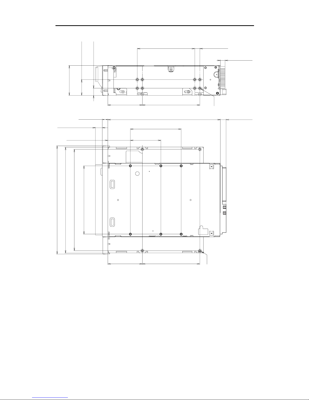
2.1.1.1. Mounting Holes
Figure 2-2a gives details of the mounting holes for the Sony SDX-900V and figure 2-2b for the Sony SDX-900V/R.
155.0 0.5mm [6.10" 0.02"]
90.0 0.3mm [3.54" 0.01"]
60.0 0.3mm
[2.36" 0.01"]
70.0 0.3mm [2.76" 0.01"]
31.0 0.3mm
[1.22" 0.01"]
21.0 0.3mm
[0.83" 0.01"]
41.2 0.5mm
[1.62" 0.02"]
4.8 0.5mm
[0.19" 0.02"]
6-M3 (depth 2.5mm [0.10"] max.)
6-M3 (depth 2.5mm [0.10"] max.)
42.0 0.3mm
[1.65" 0.01"]
94.0 0.5mm [3.70" 0.02"]
101.6 0.5mm [4.00" 0.02"]
+
_
+
_
+
_
+
_
+
_
+
_
+
_
+
_
+
_
+
_
+
_
+
_
+
_
+
_
+
_
+
_
+
_
+
_
+
_
+
_
+
_
+
_
7.4 0.6mm
[0.29" 0.02"]
+
_
+
_
9.8 0.6mm [0.39" 0.02"]
+
_
+
_
Figure 2-2a: SDX-900V Mounting Holes
2.Specification
SONY AIT-4 drive SDX-900V series Ver.2.1
2-3
79.2 0.3mm [3.12" 0.01"]
79.2 0.3mm [3.12" 0.01"]
47.5 0.3mm
[1.87" 0.01"]
79.2 0.3mm [3.12" 0.01"]
47.5 0.3mm
[1.87" 0.01"]
94.0 0.5mm [3.70" 0.02"]
21.8 0.5mm
[0.86" 0.02"]
41.2 0.5mm
[1.62" 0.02"]
9.9 0.5mm
[0.39" 0.02"]
139.6 0.5mm [5.50" 0.02"]
146.0 0.5mm [5.75" 0.02"]
149.0 0.5mm [5.87" 0.02"]
155.0 0.5mm [6.10" 0.02"]
70.0 0.3mm [2.76" 0.01"]
31.0 0.3mm
[1.22" 0.01"]
42.0 0.3mm
[1.65" 0.01"]
4-M3
6-M3
+
_
+
_
+
_
+
_
+
_
+
_
+
_
+
_
+
_
+
_
6.9 0.5mm
[0.27" 0.02"]
+
_
+
_
+
_
+
_
+
_
+
_
+
_
+
_
+
_
+
_
+
_
+
_
+
_
+
_
+
_
+
_
+
_
+
_
+
_
+
_
+
_
+
_
+
_
+
_
7.6 0.5mm
[0.30" 0.02"]
+
_
+
_
7.4 0.6mm
[0.29" 0.02"]
+
_
+
_
9.8 0.6mm
[0.39" 0.02"]
+
_
+
_
7.0 0.5mm
[0.28" 0.02"]
+
_
+
_
Figure 2-2b: SDX-900V/R Mounting Holes
2.Specification
SONY AIT-4 drive SDX-900V series Ver.2.1
2-4
2.1.2. Weight
SDX-900V 780 grams, without a cassette and a front bezel.
SDX-900V/R 1010 grams, without a cassette and a front bezel.
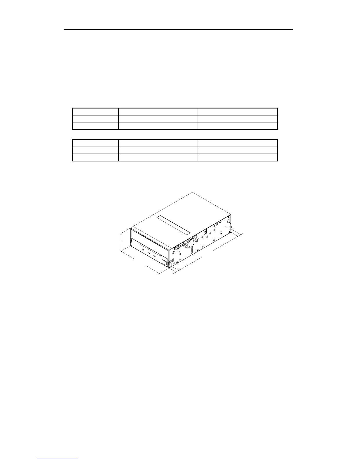
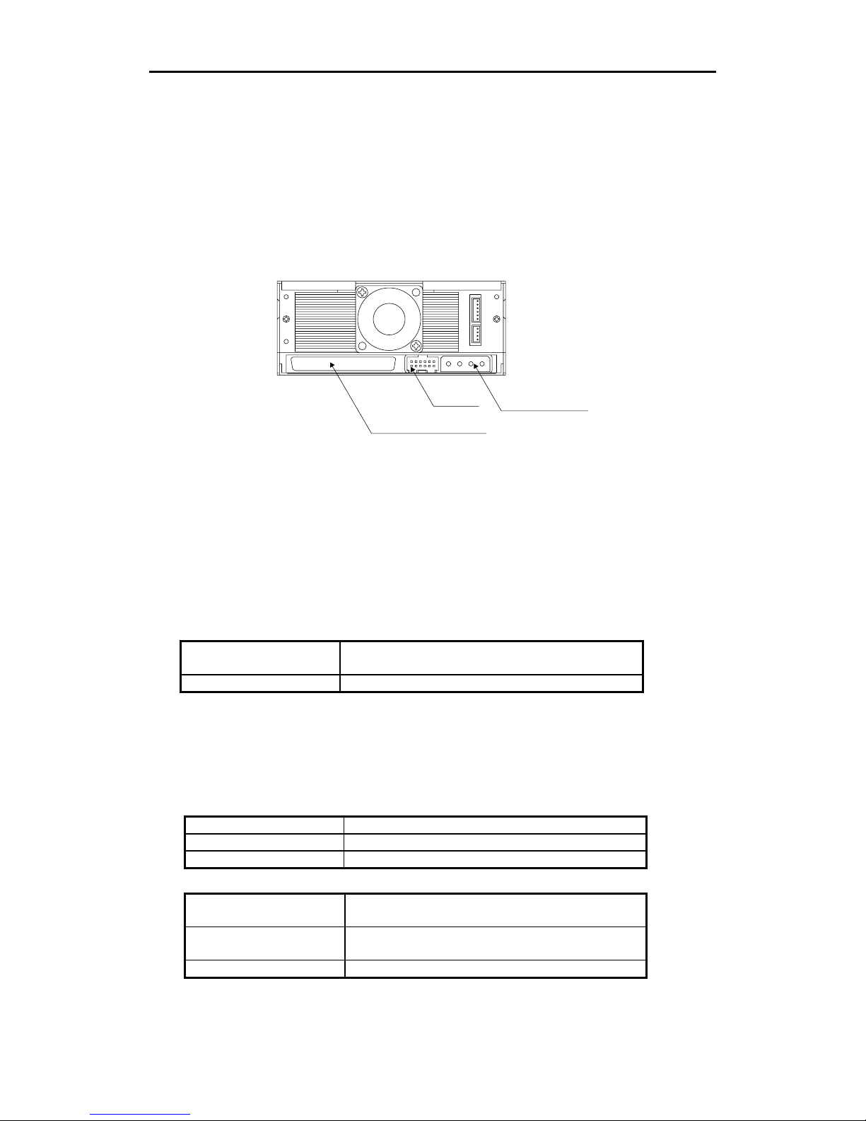
2.1.3. Connectors
The SDX-900V has a SCSI connector with a power connector and Jumpers at the positions shown in Figure 2-3. All
other connectors are for use by Sony’s manufacturing and service facilities only.
Figure 2-3: Connector Positions
2.1.3.1. SCSI Cables and Terminators
The Single-Ended SCSI configuration and Low-Voltage-differential SCSI configuration are supported by SDX-900V,
and SDX-900V/R The hardware specification of this interface can be found in Clause 3. Physical Characteristics, of
the X3T10/1142D (SCSI Parallel Interface2) standard. Only unshielded connectors are supported. Possible cable
and connector sources are listed below. This does not imply that these are the only sources for SCSI accessories.
Note: When using high speed data transfer with the SDX-900V it is recommended that total length of the SCSI data
cable not exceeded 1.5m for Single Ended SCSI configuration. As for Low-Voltage-differential SCSI configuration,
less than 12m is recommended.
Cable 30 AWG Ribbon
Hitachi UL 20848 (or equivalent)
Connector AMP 1-786090-7 (or equivalent)
2.2. Environmental Specifications
The specifications which apply when media is present may be different than these.
2.2.1. Temperature and Humidity Range
Temperature
Operating 5 ºC to 40 ºC (ΔT < 10 ºC/h)
Non-Operating(mech.) -40 ºC to 70 ºC (ΔT < 20 ºC/h)
Non-Operating(tape) -40 ºC to 45 ºC (ΔT < 20 ºC/h)
Humidity
Operating 20 to 80% RH, non-condensing
Maximum wet bulb temperature = 26 ºC
Non-operating (mech.) 5 to 95%RH(ΔRH<30%/h)
Maximum wet bulb temperature = 45 ºC
Non-operating (tape) 20 to 80%RH(ΔRH<30%/h)
.
Jumpers
SCSI 68 pin Connector
Power Connector
2.Specification
SONY AIT-4 drive SDX-900V series Ver.2.1
2-5
2.2.2. Altitude
Operating 0 to 10,000 feet
2.2.3. Suspended Particulate
Operating
Less than 150 microgram/m
3
Based Sampling period 24 hours
2.2.4. Vibration
Operating Swept Sine 5 to 500Hz, @0.25G Peak 1 Octave/min.
3 axis, 3 directions
Non-operating Swept Sine 5 to 500Hz, @ 0.5G Peak 1 Octave/min.
3 axis, 3 directions
2.2.5. Shock
Operating No Data Loss
Half Sine
Performance
5 G Peak 3 ms
3 axes, 3 directions
*Interval 10 seconds
Non-operating No Device Damage
Half Sine
90 G Peak 3 ms
(30 G Peak 11 ms)
3 axes, 3 directions
*
Interval 10 seconds
2.2.6. Acoustic Noise
The ambient noise level is no greater than 25 dB (A). The sound-meter on (A) scale is located 1m in front of the
center of the drive front panel. (A): A curve weight
Streaming Write/Read 35dB(A)
Insert/Eject 60dB(A)
2.2.7. EMC
EMI/EMS Radiated Emissions /
Conducted noise
Emissions
EN 55022 / 94 + EN 55022 A1 / 95 class B
EMS ESD
(Front Panel Only,
integrated product)
Discharge Voltage
Less than 15kV: No operation failure
Less than 20kV: No drive damage
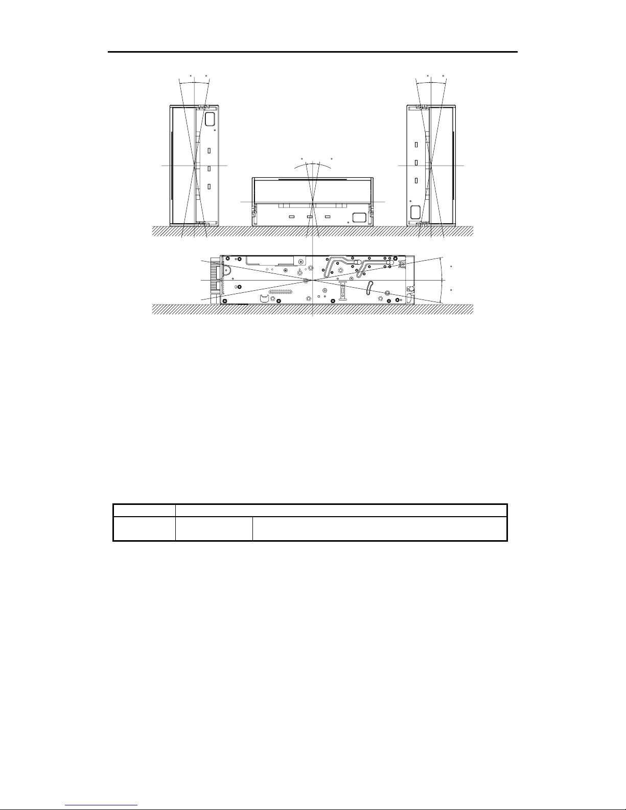
2.2.8. Orientation
The SDX-900V can be installed in three different mounting positions as shown in the figure below. Each position has
a maximum tolerance of ± 10 degrees.
2.Specification
SONY AIT-4 drive SDX-900V series Ver.2.1
2-6
10
10
10
10
10
10
10
10
Figure 2-4: Mounting Attitude and Tolerance
2.3. Performance Specification
The data capacity, data transfer rate and data reliability specifications this chapter require the media to conform to
the AIT-4 Media Specification and also require the drive and media to remain within their respective operating and
non-operating environmental specifications. The specifications below also assume that the C3 ECC fragment
(AIT-4) is generated on writing and used as necessary on reading, and further assumes that read-after-write rewrites
are used as necessary on writing.
2.3.1. Data Capacity
The SDX-900V includes a data compression capability. When data compression is enabled the drive capacity can
increase from 2 times to 3 times. The efficiency of the data compression depends on the actual data that is being
compressed and cannot be predicted precisely prior to compression.
Format AIT-4 Standard Format
Native
Capacity
200.0 Gbyte typical When using 246 meter tape AIT-4 cassette (SDX4-200C)
2.Specification
SONY AIT-4 drive SDX-900V series Ver.2.1
2-7
2.3.2. Data transfer Rate
2.3.2.1. Sustained Data Transfer Rate to and from
the Tape
The sustained transfer rate to and from the tape is 24Mbyte per second with AIT-4 cassette. For this sustained rate
to be achieved, the drive must be streaming. There may be some dependency on the host for this to be achieved.
When data compression is enabled the drive can achieve a transfer rate from 48Mbyte per second to 72Mbyte per
second with AIT-4 cassette.
2.3.2.2. Burst Transfer Rate to and from the SCSI Bus
The SDX-900V will transmit and receive data bursts to and from the SCSI bus at a maximum burst rate of 12Mbyte
per second, using Ultra 160 asynchronous transfers and maximum of 160Mbyte per second, using Ultra160
synchronous transfers.
2.3.3. Initialize Time
Initialize Time means the period from the time the drive is powered on to the time when the drive is ready and waiting
for a SCSI command such as INQUIRY or TEST UNIT READY. Initialize Time is less than 5 seconds.
The drive will respond with BUSY status until the completion of the Initialize Time. The Initialize Time does not
include the time necessary for drive diagnostics to complete and the drive to become ready for tape insertion.
2.3.4. Load Time
Load Time means the period from the time when the operator inserts a cassette into the drive to the time when the
drive is ready. The data in the below table represents the average time for SDX-900V. The time it may take for
retrying is not reflected here.
SDX4-200C (246 m)
Load Time 14 sec
2.3.5. Unload Time
Unload Time means the period from the beginning of the unload sequence caused by Unload Command or Eject
button to the time when a cassette is ejected from the slot. Unload Time does not include Rewind time. The data in
the below table represents the average time for SDX-900V. The time it may take for retrying is not reflected here.
SDX4-200C (246 m)
Unload Time 24 sec
2.3.6. Search Time
Search Time means the period for the drive to find the position that is required by a command. This time also
depends on the tape length and the position of the head along the tape. The data in the below table represents the
average time for SDX-900V. The time it may take for retrying is not reflected here.
SDX4-200C (246 m)
Search Time 130 sec
2.3.7. Rewind Time
Rewind Time means the period from the beginning to the end of rewinding sequence. This value depends on the
tape length and the position of the head along the tape. The data in the below table represents the average time for
SDX-900V. The time it may take for retrying is not reflected here.
SDX4-200C (246 m)
Rewind Time 115 sec
2.Specification
SONY AIT-4 drive SDX-900V series Ver.2.1
2-8
2.3.8. Error Rate
The un-correctable bit error rate is expected to be less than 1 in 10 to the 17th.
2.3.9. Retry Limits on Rewrites
AIT-4
For Read-after-Write error correction, each group can be rewritten up to a maximum of 14 times giving 15 times of
the group.
2.3.10. Definition of Failure
A failure is defined as any permanent manufacture of the drive that prevents the user from retrieving data from tape.
This includes failure to power up, failure to unload or eject a cassette, or failure to write and read data to and from the
tape, providing that both the drive and tape are being used within specification.
Faults are not considered failures when they are related to operator error mishandling and abuse, system-related
faults (cabling problems unsupported systems, operating software and so on) no trouble found, and transportation
damage.
2.3.11. Mean Time Between Failures
The Mean Time Between Failures (MTBF) for the SDX-900V is 400,000 power-on hours, assuming a duty cycle of
100%, where:
DutyCycle =
TapeMotion Time
PowerOn Time
× 100
2.3.12. Mean Time to Repair
The Mean Time To Repair (MTTR) of the SDX-900V is 30 minutes. Since at the field level the entire drive is
considered a Field Replaceable Unit (FRU) the time to replace the drive with a new one is less that 30 minutes.
2.3.13. Component Life
The specified life of the SDX-900V is 5 years average.
2.3.14. Durability
The durability of the components in the SDX-900V will exceed the number of operations listed on the following table:
Start/Stop 400,000 times
Reposition 3,000,000 times
Thread/Unthread 100,000 times
Load/Eject 100,000 times
2.Specification
SONY AIT-4 drive SDX-900V series Ver.2.1
2-9
2.4. Safety
The SDX-900V conforms to the following safety standards:
• UL/cUL (Underwriters Laboratories, Inc.)
UL 60950 3rd Edition/CSA C22.2 No. 60950-00
Safety of Information Technology Equipment.
• TUV
IEC 950 Safety of Information Technology Equipment including
Electrical Business Equipment (First Edition)
• CE Mark
2.4.1. Conditions of Acceptability
The SDX-900V is for use only in equipment where the suitability of the combination has been determined by an
appropriate certification organization (for example, Underwriters Laboratories, Inc. or the Canadian Standards
Association in North America, and the British Standards Institution or Verband Deutscher Elektrotechniker in
Europe). Other considerations include the following:
1. An enclosure must be supplied to limit the operator’s access to live parts, to provide system stability, and to
furnish the drive with the necessary grounding integrity.
2. The necessary voltage supplies must be provided. These supplies are Extra Low Voltage SEC for UL and
CSA, or Safety Extra Low Voltage for BSI, VDE, and so on, of +5V and +12V DC.
2.5. Installation Requirements
Note: Do not move the drive while it is operating. It may cause malfunction.
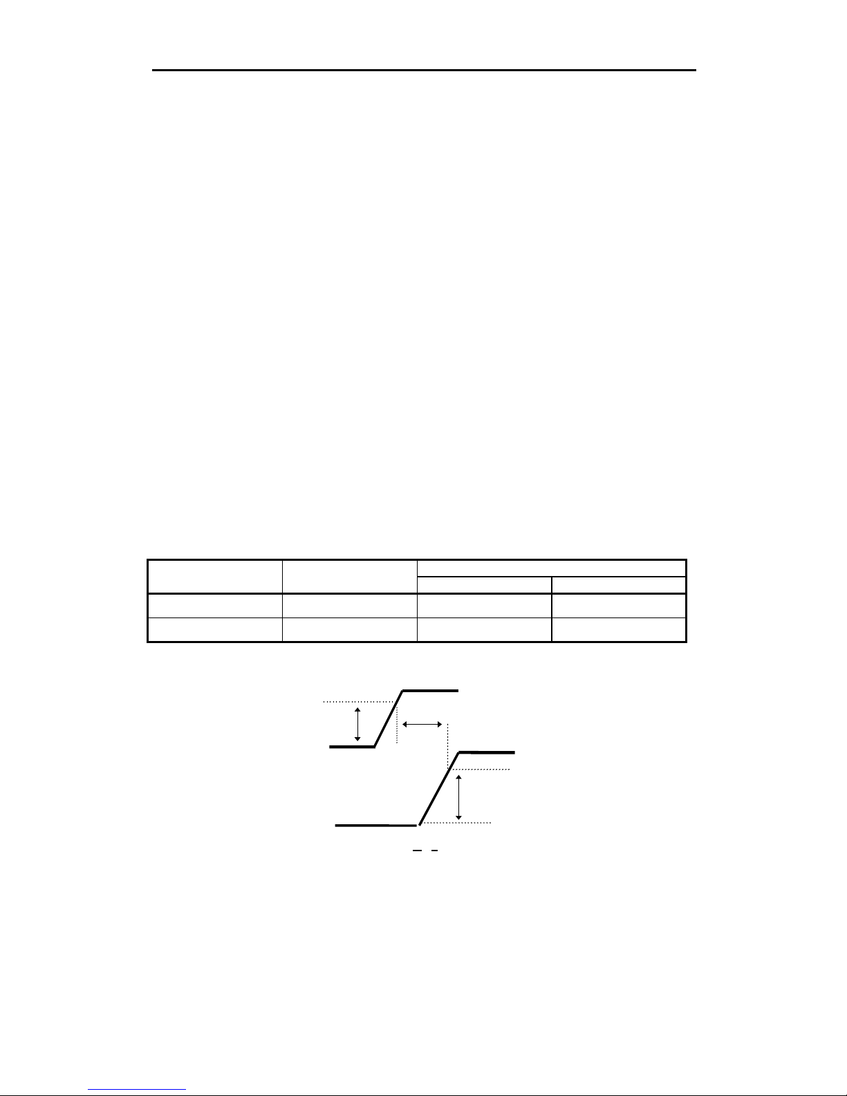
2.5.1. Power Requirements
Voltage Max Ripple Current
Typical Maximum
5V ± 5% 100 mV p-p 1.5A 2.5A
12V ± 10% 150 mV p-p 0.75A 3.0A
* exclude SCSI terminator power
4.75V
T
10.8V
0V
0V
5V
12V
-300 ms <
T < 300 ms
Figure 2-5: Power-up Sequence
Note: Voltage has to increase constantly during Power-up until Maximum is reached.
Do not turn off the drive while the tape is in the drive.

2.Specification
SONY AIT-4 drive SDX-900V series Ver.2.1
2-10
2.6. Data Compression
The tape capacity is increased by compressing data prior to writing it to the tape. Data compression is a well
established technology for reducing the number of bits used to represent data in order to improve data transfer rate
as well as reduce the amount of storage space consumed by the data. The compression ratio depends on the source
file type. The SDX-900V uses the ALDC Data Compression algorithm. ALDC is ECMA standard data compression
algorithm. (ECMA-222) The Data Compression control page allows the host computer to enable data compression
and decompression and also configure the way in which the drive responds to compressed/uncompressed data
boundaries on the tape. The AIT-4 Format allows both compressed and uncompressed data to reside on the same
tape.
The Sony SDX-900V has a DIP switch to disable the Data Compression/ Decompression. After power-on reset with
this DIP switch set, both data compression and data decompression are disabled However, a MODE SELECT
command can override the setting of this DIP switch. After power-on reset without this DIP switch set, both data
compression and data decompression are enabled. (See clause 3.1.4)

3.Installation
SONY AIT-4 drive SDX-900V series Ver.2.1
3-1
3. Installation
3.1. Installation Guide
This Product Specification Manual is applicable for AIT-4 drive.
Dip switch
Jumpers
SCSI 68 pin Connector
Power Connector
Figure 3-1: DIP switch & Connector
3.Installation
SONY AIT-4 drive SDX-900V series Ver.2.1
3-2
1 DR (Desaster Recovery) Mode
2 Emulation Mode
3 AIT Library Interface Mode
4 Reserved
5 Terminator Power (ON)
6 Periodic Cleaning Req (ON)
7 DC Control-1
8 DC Control-2
1 2 3 4 5 6 7 8
ON
OFF
Figure 3-2: DIP Switch Positions
Table 3-1: Drive Mode
DIP SW 1 2 3 4 MODE
OFF OFF ON OFF
Normal
ON OFF OFF OFF
DR Mode
OFF ON OFF OFF SDX-700C Emulation Mode
OFF OFF
ON
OFF
Library Mode
Table 3-2: Periodic Cleaning Request (Refer to 4.6.1.2)
DIP SW 6 Definition
OFF Disable Periodic Cleaning Request
ON Enable Periodic Cleaning Request
3.1.1. SCSI ID Number Jumper
The SCSI ID number of the SDX-900V is selected by the SCSI ID number jumpers. The figure below shows the
jumper configuration for each of the possible SCSI IDs.
SCSI ID3 ID2 ID1 ID0
0 : : : :
1 : : : |
2 : : | :
3 : : | |
4 : | : :
5 : | : |
6 : | | :
7 : | | |
8 | : : :
9 | : : |
10 | : | :
11 | : | |
12 | | : :
13 | | : |
14 | | | :
15 | | | |
: = OPEN Jumper not installed
| = CLOSED Jumper installed
3.1.2. Termination Power Switch
Position 5 of DIP switch is used to set whether SDX-900V provides the termination power to pin 17,18,51,52 on SCSI
bus, or not.
Parity Disable
N o C o n n e c tio n
ID3
ID2
ID1
ID0
Figure 3-3: Jumper positions
3.Installation
SONY AIT-4 drive SDX-900V series Ver.2.1
3-3
3.1.3. Parity Disable Jumper
Parity check function can be disabled by Jumper. Parity check is disabled while left end jumper is installed. Parity
generate function is always enabled.
Parity Setting
Disable |
Enable :
: = OPEN Jumper not installed
| = CLOSED Jumper installed
3.1.4. Data Compression ON Switch
Data compression can be selected by DIP switch.
Table 3-3: Data Compression Switches
DC Control-1 DC Control-2 Definition
OFF OFF Compression disabled at power-on. The host is allowed to control
compression.
OFF ON Compression disabled at power-on. The host is not allowed to control
compression.
ON OFF Compression enabled at power-on. The host is allowed to control
compression.
ON ON Compression enabled at power-on. The host is not allowed to control
compression.
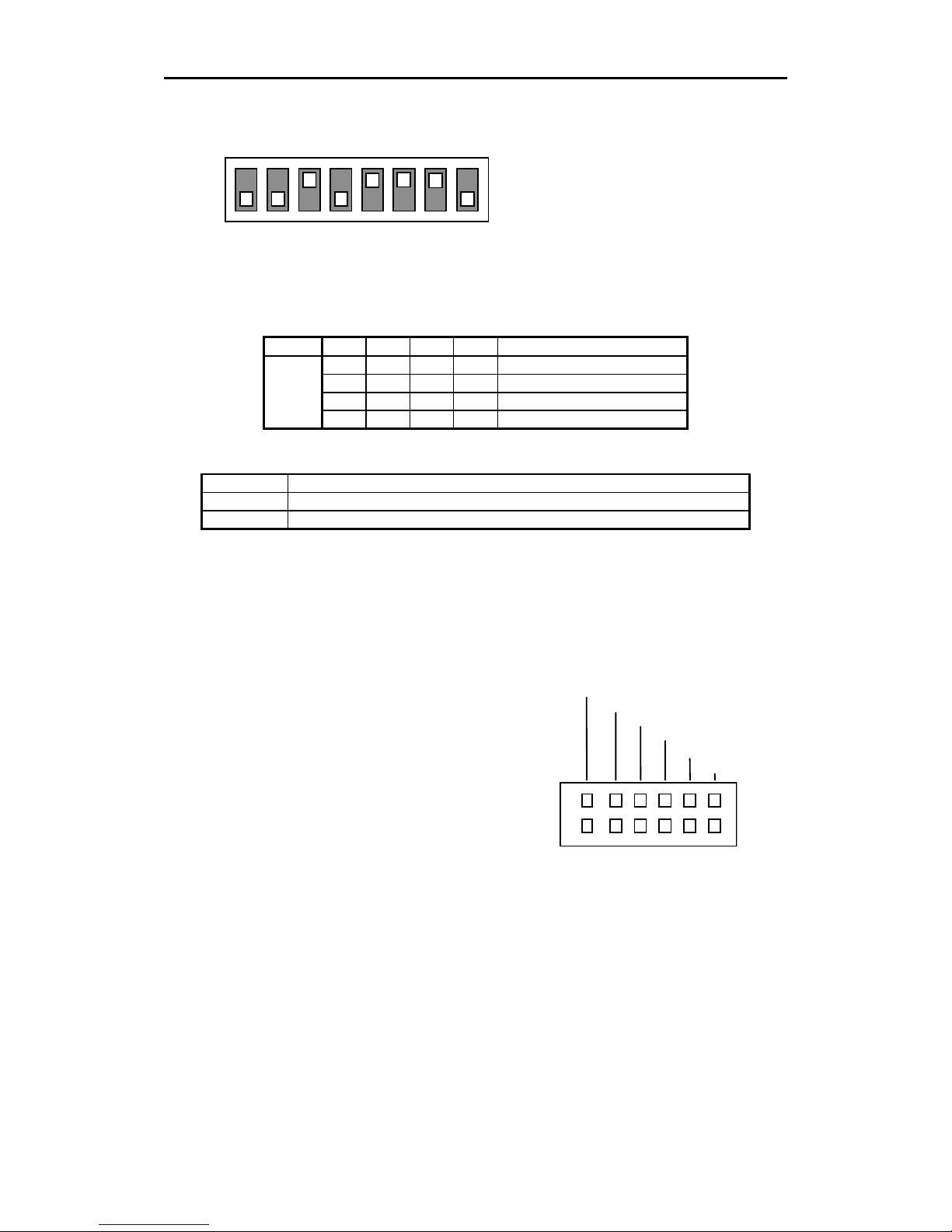
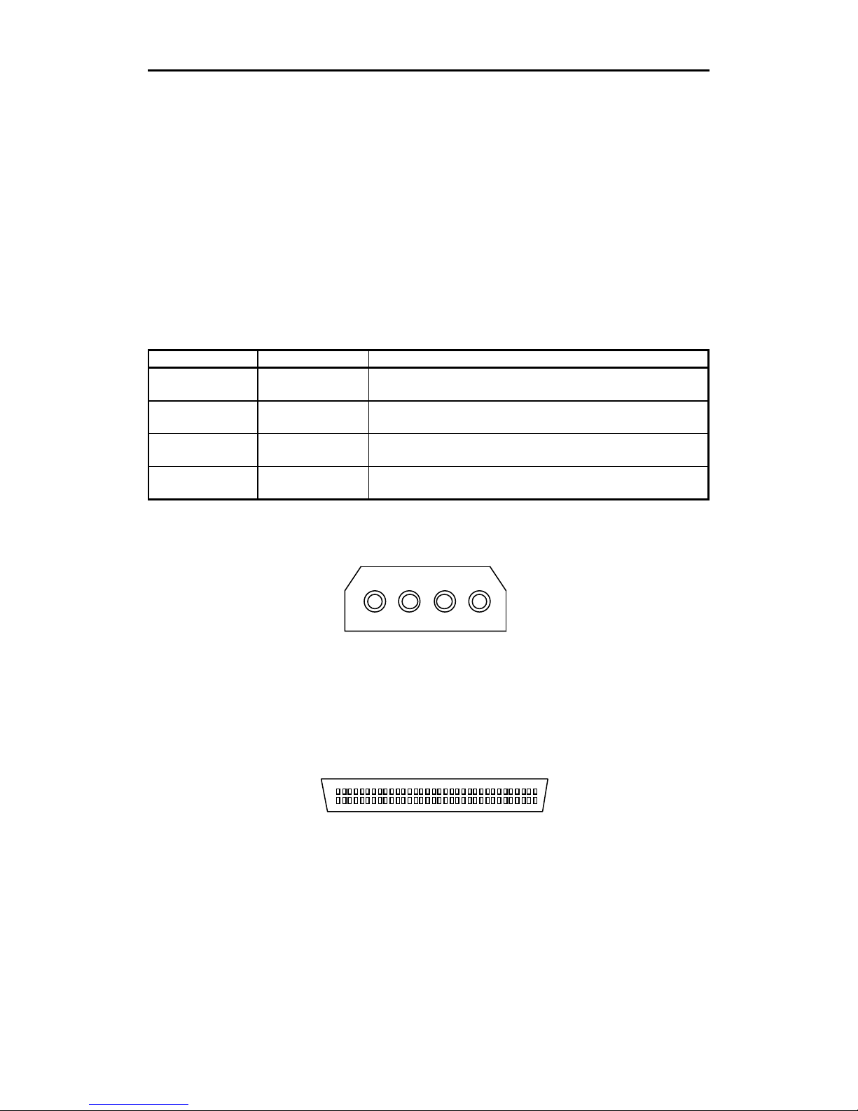
3.1.5. Power Connector
The power connector is illustrated as Figure 3-4.
5V GND GND 12V
4 3 2 1
Figure 3-4: Power Connector
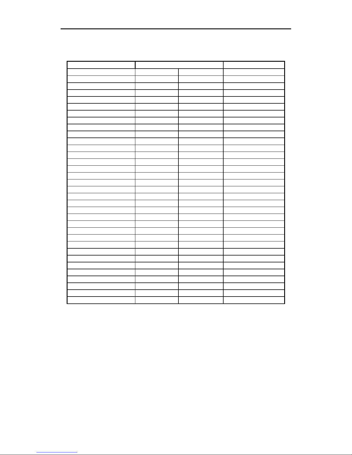
3.1.6. SCSI 68 pin Connector
Figure 3-5 illustrates SCSI 68 pin connector, and table 3-4 shows the assignments for the pins of the connector.
Pin 34 1
Pin 68 35
Figure 3-5: Non-shielded SCSI Device Connector
SDX-900V supports both Low-Voltage-Differential SCSI configuration as shown table 3-4 and Single-Ended SCSI
configuration as shown table 3-5. SDX-900V detects and switches SCSI configuration between
Low-Voltage-Differential and single-ended modes by monitoring DIFFSENS signal assigned pin 16 in SCSI bus.
(Refer to table 3-4)
3.Installation
SONY AIT-4 drive SDX-900V series Ver.2.1
3-4
Table 3-4: SDX-900V SCSI Signals
(Low-Voltage-Differential Type BUS P Cable Signal Assignment)
Signal Name Cable Conductor Number Signal Name
-DB(12) 35 1 +DB(12)
-DB(13) 36 2 +DB(13)
-DB(14) 37 3 +DB(14)
-DB(15) 38 4 +DB(15)
-DB(P1) 39 5 +DB(P1)
-DB(0) 40 6 +DB(0)
-DB(1) 41 7 +DB(1)
-DB(2) 42 8 +DB(2)
-DB(3) 43 9 +DB(3)
-DB(4) 44 10 +DB(4)
-DB(5) 45 11 +DB(5)
-DB(6) 46 12 +DB(6)
-DB(7) 47 13 +DB(7)
-DB(P) 48 14 +DB(P)
GROUND 49 15 GROUND
GROUND 50 16 DIFFSENS
TERMPWR 51 17 TERMPWR
TERMPWR 52 18 TERMPWR
RESERVED 53 19 RESERVED
GROUND 54 20 GROUND
-ATN 55 21 +ATN
GROUND 56 22 GROUND
-BSY 57 23 +BSY
-ACK 58 24 +ACK
-RST 59 25 +RST
-MSG 60 26 +MSG
-SEL 61 27 +SEL
-C/D 62 28 +C/D
-REQ 63 29 +REQ
-I/O 64 30 +I/O
-DB(8) 65 31 +DB(8)
-DB(9) 66 32 +DB(9)
-DB(10) 67 33 +DB(10)
-DB(11) 68 34 +DB(11)
 Loading...