

Sony SDX-700 Series, SDX-710 Series User Manual

AIT Drive
User’s Guide
4-658-155-04(1)
SDX-700 Series
SDX-710 Series
2001 Sony Corporation

This document contains proprietary
information which is protected by
copyright.
All rights reserved. No part of this
document may be photocopied,
reproduced or translated to another
language without prior written consent
of Sony.
The information contained in this
document is subject to change without
notice.
SONY MAKES NO WARRANTY
OF ANY KIND WITH REGARD TO
THIS DOCUMENT.
Sony shall not be liable for error
contained herein, indirect, special,
incidental or consequential damages in
connection with the furnishing,
performance or use of this document.
VORSICHT
Diese Ausrüstung erfüllt die
Europäischen EMC-Bestimmungen für
die Verwendung in folgender /
folgenden Umgebung(en):
• Wohngegenden
• Gewerbegebiete
• Leichtindustriegebiete
(Diese Ausrüstung erfüllt die
Bestimmungen der Norm EN55022,
Klasse B.)
Contents
Introduction .......................................4
Product Features........................4
Precautions ................................5
Installation .........................................7
SCSI Connection/Setting the
SCSI ID (SDX-700C)............7
SCSI Connection/Setting the
SCSI ID (SDX-710C)............8
Option Switches (DIP Switch) ..9
Mounting Holes......................10
Remodeling from 5.25" Model
to 3.5" Model .......................13
Orientation...............................14
Operation .........................................15
Location of 3 LEDs ................. 15
LED Indication for
Drive Status .........................15
Drive Operation.......................16
Emergency Cassette Removal
Procedure .............................17
Interface Implementation.................20
Supported SCSI Messages ......20
Supported SCSI Commands....20
Specification ....................................21
Product Specifications.............21
Third Party Support Contacts
(In the USA) ...............................23
Sony Contacts .................................. 25
2

SDX-700 Tape Drive
The Sony SDX-700 series drive is a high capacity data storage device using
Advanced Intelligent tape (AIT) technology. The SDX-700 series drive
achieves high data reliability through Read-After-Write, an additional level
of Error Correction Code, and other features.
The Sony SDX-700 series drive stores data on tape using a standard format
called AIT (Advanced Intelligent Tape) and ALDC formats.
3

Introduction
Product Features
SDX-700 series
Data Capacity
Transfer Rate (sustained)
* Assuming a 2.6 : 1 compression ratio.
(The compression ratio varies according to the type of data.)
• Supported Format : AIT-1, AIT-2, AIT-3
• Burst Transfer Rate
– 12 MB/s Asynchronous
– 160 MB/s Synchronous (SDX-700C)
– 40 MB/s Synchronous (SDX-710C)
• 18 MB Buffer Memory
• 3.5” Standard Height, 5.25” Half Height
• Embedded SCSI Interface
– Ultra 160 Wide LVD/SE SCSI (SDX-700C)
– Ultra Wide HVD SCSI (SDX-710C)
• Supports Variable or Fixed Record Length
• Supports SCSI Disconnection/Arbitration
• Frame Rewrite Function
• Three levels of Error Correction Code (ECC)
• High Speed search (120 times normal Read/Write speed of AIT-3 mode)
• Random Read, Append Write
100 GB uncompressed (with AIT-3 230 m tape)
260 GB compressed* (with AIT-3 230 m tape)
12 MB/s uncompressed
4

Precautions
Installation
Avoid placing the drive in a location subject to:
– high humidity
– high temperature
– mechanical shock and vibration
– direct sunlight
Operation
• Do not move the drive while it is operating. It may cause malfunction.
• Avoid exposing the drive to sudden changes from a low to high in
temperature. This may cause water condensation to collect inside the
drive. If the ambient temperature should suddenly rise while the drive is
turned on , wait at least one hour before turning on the drive. If you
attempt to operate the drive immediately after a sudden increase in
temperature, a malfunction may occur.
• Turning off the power to the drive while it is writing to tape may cause
the tape to become unreadable. All previously negotiated parameters will
be lost, whenever power to the drive is cycled.
• Upon execution of the hardware reset hole, the driver will be reset and
there is a risk of lost and unreadable data. Thus, please do not use the
hole other than repair purposes. (See page 15)
Transportation
• Keep the original packing materials to facilitate transportation of the
drive.
• Always remove the tape before moving the drive. After removing the
drive from the computer, repack the drive into its original packing.
5
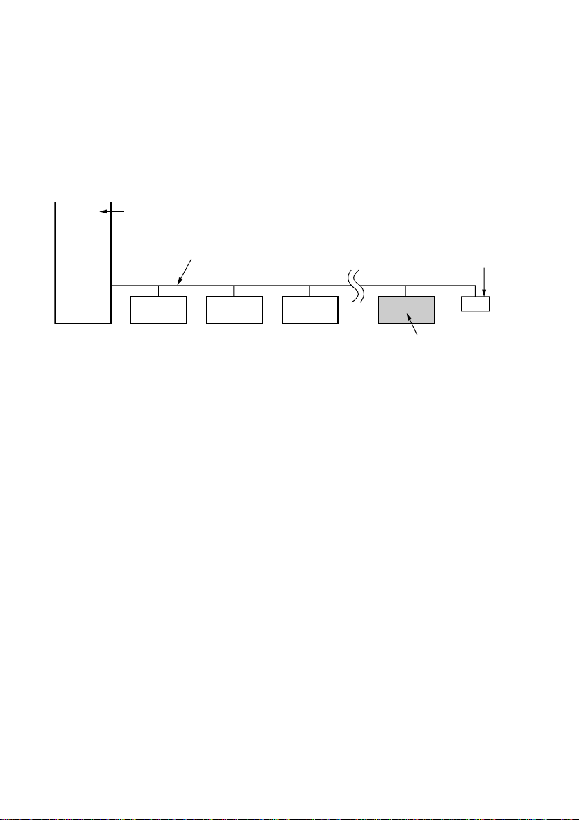
Notice of SCSI Termination
r
The SDX-700C and SDX-710C conform to the Microsoft PC97 standard
which requires the internal (naked) drive to be terminated with an external
terminator.
Microsoft PC97 SCSI requirements
SCSI peripherals must not terminate the bus. Both internal and external cable ends are
instead terminated by plug-in connectors.
Host Computer Wide SCSI
68p cable
Example of SCSI set-up
Terminato
This drive
6
Installation
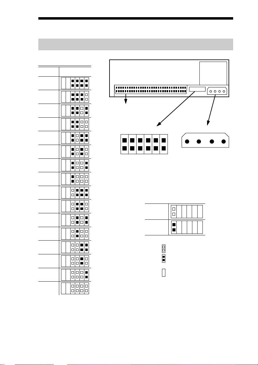
SCSI Connection/Setting the SCSI ID (SDX-700C)
SCSI ID
210
SCSI ID
0
1
P.D.
N.C.
3
10
11
12
13
14
2
3
4
5
SCSI 68pin Connector
Jumpers
Power Connector
5 V
GND GND 12 V
1234
6
SCSI ID 3
SCSI ID 2
SCSI ID 1
7
Parity Disable
8
No Connection
Parity
SCSI ID 0
9
Disable
Enable
Note := = CLOSED/Jumper
OPEN/Jumper not
installed
Don’t care
15
Parity Disable Jumper
Parity check function can be disabled by Jumper. Parity check is disabled
while left end jumper is installed. Parity generate function is always
enabled.
7
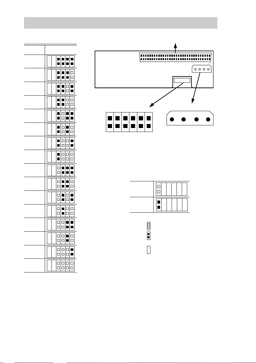
SCSI Connection/Setting the SCSI ID (SDX-710C)
SCSI ID
SCSI ID
0
1
2
3
4
5
6
7
8
9
10
11
SCSI 68pin Connector
210
3
P.D.
N.C.
Jumpers
SCSI ID 3
Parity Disable
No Connection
SCSI ID 2
SCSI ID 1
SCSI ID 0
Power Connector
5 V
GND GND 12 V
1234
Parity
Disable
Enable
12
13
14
Note := = CLOSED/Jumper
OPEN/Jumper not
installed
Don’t care
15
Parity Disable Jumper
Parity check function can be disabled by Jumper. Parity check is disabled
while left end jumper is installed. Parity generate function is always
enabled.
8
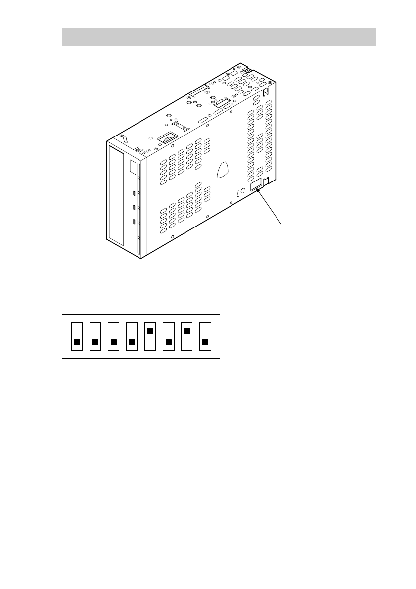
Option Switches (DIP Switch)
DIP Switch Positions
DIP Switch
ON
12345678
1 Reserved (OFF)
2 Reserved (OFF)
3 Reserved (OFF)
4 Reserved (OFF)
5 Terminator Power (ON)
6 Reserved (OFF)
7 DC Control (1) (ON)
8 DC Control (2) (OFF)
Data Compression Control DIP switch
Data compression can be selected by DIP switches. Data compression is
enabled while position 7 [DC Control (1)] is ON. Control by host can be
disabled when position 8 [DC Control (2)] is ON.
9
 Loading...