

Sony AIT-SDX570, SDX-570V/P, SDX-570V/RP Product Specifications Manual

SDX-570V/P
SDX-570V/RP
5.25 Model
Product Specification Manual
Version 1.0
Aug. 2005
Copyright © 2005, Sony Corporation.
All right reserved.
NOTE:
This Product Specification Manual is applicable for AIT-2 Turbo Serial ATA I/F drive.

Notice
This document contains proprietary information which is protected by copyright. All rights reserved. No part of this
document may be photocopied, reproduced or translated to another language without prior written consent of
Sony. The information contained in this document is subject to change without notice.
SONY MAKES NO WARRANTY OF ANY KIND WITH REGARD TO THIS DOCUMENT. Sony shall not be liable
for errors contained herein, or indirect, special, incidental or consequential damages in connection with the
furnishing, performance, or use of this document.
© Copyright 2005, by Sony Corporation
For further information , please contact the appropriate Sony location listed below;
Sony Electronics Inc., Tape Storage Solutions (USA)
URL: http://www.storagebysony.com
Sony Australia Limited
33-39 Talavera Rd.
NORTH RYDE, NSW 2113
TEL: 1300-13-7669 FAX: 02-9870-5864
e-mail: CIC-customerissues@ap.sony.com
Sony of Canada Ltd., AV/IT Marketing Group
Computer Peripherals Product Marketing
115 Gordon Baker Road Toronto, Ontario, M2H 3R6 Canada
TEL: (416) 499-1414 or (1) 800-961-7669
FAX: (416) 499-8541
Sony New Zealand
Akoranga Business Park
NORTH SHORE, AUCKLAND
TEL: 0800-76-6969 FAX: 09-308-9300
e-mail: CIC-customerissues@ap.sony.com
Sony Business Europe
URL: http://www.sonyisstorage.com/
Sony Chile Ltda
Av. Kennedy 8017, Las Condes, Santiago, Chile
TEL: (02) 210-6000 FAX: (02) 210-5417
Electronics Devices Marketing (Singapore)
(A division company of Sony Electronics (S) Pte. Ltd.)
Enterprise Storage Solutions Dept.
2 International Business Park, #01-10 Tower One,
The Strategy, Singapore 609930
TEL: 65-6544-8000 FAX: 65-6544-7390
Sony Taiwan Limited
Optical Devices Storage Dept. Data Storage Section
5F, 145 Changchun Road, Taipei 104, Taiwan
TEL: 886-2-2522-7920 FAX: 886-2-2522-2153
Sony Corporation of Hong Kong Ltd.
Computer Peripheral Sales & Marketing Division
Electronic Devices Marketing Hong Kong
45/F, The Lee Gardens, 33 Hysan Avenue, Causeway Bay, Hong Kong
TEL: (852) 2909-1008 FAX: (852) 2909-2001
Sony Korea Corporation EDMK CP Sales & Marketing Team
34F, ASEM Tower, World Trade Center, 159-1, Samsung-Dong,
Kangnam-Ku, Seoul, 135-798, Korea
TEL: 82-2-6001-4249 FAX: 82-2-6001-4115
URL: http://www.sony.co.kr/cp/
Sony Corporation of Hong Kong Ltd. Beijing Rep. Office
Computer Peripheral Div.
Full Link Plaza Tower A 11/F., No.18 Chaoyangmenwai Ave., Beijing
100020 P.R.C.
TEL: 86-10-6588-0633 FAX: 86-10-6588-0855
URL: http://www.sony.com.cn/ed/cp/ait/
Sony Gulf FZE Computer Display & Peripheral Div.
P.O.BOX 16871, Jebel Ali, Dubai, U.A.E.
TEL: 971-4-8815488 or 8816912 FAX: 971-4-8817210 or 8816259
Sony Corporation of Hong Kong Ltd.,
Electronic Devices Marketing Hong Kong
Computer Peripherals Sales & Marketing Div.
8/F, One Corporate Avenue, 222 Hu Bin Road. Luwan District,
Shanghai. P.R.C. Postcode 200021
TEL: 86-21-6121-6878
URL: http://www.sony.com.cn/ed/cp/ait/
Sony Marketing of Japan
Business Solution Dept. Server Solution Marketing Section
URL: http://www.sony.co.jp/STORAGE
Sony Brasil Ltda.
Rua InocŽncio Tobias, 125-BlocoA, CEP01144-000, Săo Paulo-SP-Brasil
TEL: (55) 11-3824-6586 to 6598 FAX: (55) 11-3611-9064
URL: http://www.sonybrasil.com

Changing List
Page Clause Title Modify Add Delete Remarks
SDX-570V Series Ver. 1.0 AUGUST, 2005 (RELEASE)

This page intentionally left blank.

SDX-570V series Ver.1.0 Table of Contents
Table of Contents
1. Introducin 1-1
1.1. About This Product Specification Manual 1-1
1.2. Introducing the Sony AIT Technology 1-1
1.3. Features of the Drive 1-1
1.4. Reference 1-2
1.4.1. How to get ECMA-222, 246, 291, 292 Standard Document 1-2
2. Specifications 2-1
2.1. Specifications 2-1
2.1.1. Dimensions 2-1
2.1.1.1. Mounting Holes 2-2
2.1.2. Weight 2-4
2.1.3. Connectors 2-4
2.1.3.1. Serial ATA Cables 2-4
2.2. Environmental Specifications 2-4
2.2.1. Temperature and Humidity Range 2-4
2.2.2. Altitude 2-4
2.2.3. Suspended Particulate 2-5
2.2.4. Vibration 2-5
2.2.5. Shock 2-5
2.2.6. Acoustic Noise 2-5
2.2.7. ESD 2-5
2.2.8. EMI 2-5
2.2.9. Orientation 2-6
2.3. Performance Specification 2-6
2.3.1. Data Capacity 2-7
2.3.2. Data transfer Rate 2-7
2.3.2.1. Sustained Data Transfer Rate to and from Tape 2-7
2.3.2.2. Burst Transfer Rate to and from the Serial ATA 2-7
2.3.3. Initialize Time 2-7
2.3.4. Load Time 2-8
2.3.5. Unload Time 2-8
2.3.6. Search Time 2-8
2.3.7. Rewind Time 2-8
2.3.8. Error Rate 2-8
2.3.9. Retry Limits on Rewrites 2-8
2.3.10. Definition of Failure 2-8
2.3.11. Mean Time Between Failures 2-9
2.3.12. Mean Time to Repair 2-9
2.3.13. Component Life 2-9
2.3.14. Durability 2-9
2.4. Safety 2-9
2.4.1. Conditions of Acceptability 2-9
2.5. Installation Requirements 2-9
2.5.1. Power Requirements 2-10
2.6. Data Compression 2-10
3. Installation 3-1
3.1. Installation Guide 3-1
3.1.1. Data Compression ON Switch 3-2
3.1.2. Legacy Power Connector 3-2
3.1.3. SATA Interface Connector 3-2
3.1.4. Attaching and Removing the Dust Cover 3-4
3.1.4.1. Attaching the Dust Cover 3-4
3.1.4.2. Removing the Dust Cover 3-5

SDX-570V series Ver.1.0 Table of Contents
4. Operation 4-1
4.1. Summary of LED Indications 4-1
4.2. Operator Action 4-2
4.2.1. Powering Up the SDX-570V 4-2
4.2.2. Inserting Cassettes 4-2
4.2.3. Removing Cassettes 4-2
4.2.4. Hard Reset Hole 4-2
4.2.5. Write-Protecting Cassettes 4-3
4.3. Internal Function 4-3
4.3.1. The Load Sequence (Effective for SDX-T3N, TAITE-20N,TAIT-40N and TAIT2-80N) Refer to
14.2.1 Fast Media Load/Unload (Effective for SDX1-25C, SDX1-35C, TAIT-40C and
TAIT2-80C MIC cassette) 4-3
4.3.2. The Unload Sequence (Effective for SDX-T3N, TAITE-20N, TAIT1-40N and TAIT2-80N)
Refer to 14.2.1 Fast Media Load/Unload (Effective for SDX1-25C, SDX1-35C, TAIT1-40C
and TAIT2-80C MIC cassette) 4-3
4.3.3. Power-Fail Handling 4-4
4.3.4. Diagnostic and Normal Status Displays 4-4
4.3.4.1. Diagnostic Status Display 4-4
4.3.4.2. Normal Status Display 4-5
4.4. Tape Format 4-5
4.4.1. Tape Partitions 4-5
4.4.1.1. Formatting Partitions 4-5
4.5. Maintenance, Troubleshooting and Service 4-6
4.5.1. Head Cleaning 4-6
4.5.1.1. Message When Cleaning Cartridge is Necessary 4-6
4.5.1.2. The Condition of Cleaning Request 4-6
4.5.1.3. Usage of Cleaning Cartridge 4-6
4.5.2. Troubleshooting Guide 4-6
4.5.2.1. Operational Problems 4-7
4.5.2.2. Read/Write Problems 4-9
4.5.2.3. Replace Tape 4-9
4.5.2.4. Media Warning 4-9
4.5.3. Clearance for Service 4-9
4.5.4. Packaging for Return to Sony 4-9
5. Serial ATA Interface 5-1
5.1. Introduction 5-1
5.2. Overview of Interface 5-1
5.2.1. Device Registers 5-1
5.2.2. Interrupts 5-4
6. ATA COMMAND Specification 6-1
6.1. Check Power Mode (E5h) 6-2
6.2. Device Reset (08h) 6-4
6.3. Execute Device Diagnostics (90h) 6-5
6.4. Identify Device (ECh) 6-7
6.5. Identify Packet Device (A1h) 6-8
6.6. Idle Immediate (E1h) 6-16
6.7. NOP (00h) 6-18
6.8. Packet (A0h) 6-19
6.9. Read Sectors (20h) 6-23
6.10. Set Features (EFh) 6-24
6.11. Sleep (E6h) 6-26
6.12. Standby Immediate (E0h) 6-28

SDX-570V series Ver.1.0 Table of Contents
7. ATAPI Packet Command Specification 7-1
7.1. ERASE 19h 7-2
7.2. INQUIRY 12h 7-3
7.3. LOAD/UNLOAD 1Bh 7-7
7.4. LOCATE 2Bh 7-8
7.5. LOG SELECT 4Ch 7-9
7.6. LOG SENSE 4Dh 7-11
7.6.1. The Log Page Descriptor 7-12
7.6.2. The Log Parameter Descriptor 7-13
7.6.3. Supported Pages 7-14
7.6.4. Write and Read Error Counter Pages Code 02h & 03h 7-14
7.6.5. Last N Error Events List Page Code 07h 7-15
7.6.6. Tape Log Page (Sony Unique) Page Code 30h 7-15
7.6.7. Tape Capacity Log Page 7-17
7.6.8. Drive Usage Log Page (Sony Unique) Code 33h 7-18
7.6.9. Read and Write Frame Error Counter Page Codes 34h, 35h 7-19
7.6.10. Data Compression Transfer Log Page Code 39h 7-20
7.6.11. AIT Log Page Code 3Ch 7-21
7.7. MODE SELECT 15h 7-23
7.8. MODE SENSE 1Ah 7-25
7.8.1. Disconnect-Reconnect Page 02h 7-27
7.8.2. Data Compression Control Page 0Fh 7-27
7.8.3. Device Configuration Page 10h 7-29
7.8.4. Medium Partition Page 11h 7-31
7.8.5. Medium Partition Page 11h (for multi-partitioned tapes) 7-33
7.8.6. Informational Exceptions Control Page 1Ch 7-35
7.8.7. AIT Device Configuration Page 31h 7-36
7.8.8. Append Partition Page 32h 7-37
7.8.9. Delete Partition Page 33h 7-38
7.8.10. Capabilities and Mechanical Status Page 2Ah 7-39
7.9. PREVENT ALLOW MEDIUM REMOVAL 1Eh 7-41
7.10. READ 08h 7-42
7.11. READ BLOCK LIMITS 05h 7-44
7.12. READ BUFFER 3Ch 7-45
7.13. READ POSITION 34h 7-47
7.14. RECEIVE DIAGNOSTIC RESULTS 1Ch 7-49
7.15. RELEASE UNIT 17h 7-51
7.16. REQUEST BLOCK ADDRESS 02h 7-52
7.17. REQUEST SENSE 03h 7-53
7.18. RESERVE UNIT 16h 7-59
7.19. REWIND 01h 7-60
7.20. SEND DIAGNOSTIC 1Dh 7-61
7.21. SPACE 11h 7-63
7.22. TEST UNIT READY 00h 7-66
7.23. VERIFY 13h 7-67
7.24. WRITE 0Ah 7-69
7.25. WRITE BUFFER 3Bh 7-70
7.26. WRITE FILEMARK 10h 7-72
8. Drive Diagnostics 8-1
8.1. Overview 8-1
8.2. Diagnostic Test 8-1
8.2.1. Power-on Self Test 8-1
8.2.2. SEND DIAGNOSTIC Command-Self Test 8-2
8.2.3. SEND DIAGNOSTIC Command-Individual Test 8-2
8.2.4. Diagnostic Test Number Summary 8-3
8.2.5. RECEIVE DIAGNOSTIC RESULT Command 8-4
8.2.6. Diagnostics Results Reference 8-6
8.2.7. Diagnostic Tests Requiring Additional Parameters 8-7

SDX-570V series Ver.1.0 Table of Contents
9. APPENDIX A: ASC & ASCQ Alphabetic Order 9-1
10. APPENDIX B: ASC & ASCQ Numeric Order 10-1
11. APPENDIX C: ATA Commands (Op Code Order) 11-1
12. APPENDIX D: ATAPI Commands (Op Code Order) 12-1
13. APPENDIX E: ASC & ASCQ for AIT (Sony Unique) 13-1

1. Introduction
SONY AIT-2 Turbo drive SDX-570V series Ver.1.0 1-1
1. Introduction
1.1. About this Product Specification Manual
This Product Specification Manual is applicable for AIT-2 Turbo drive.
This manual provides information about the Sony SDX-570V series Advanced Intelligent Tape Drives which is
necessary to integrate the drives into OEM products. This manual describes the specifications, Serial ATA Interface,
diagnostics, operation and installation of the Sony SDX-570V Drives.
The Sony SDX-570V drive uses data compression to achieve high capacity and high transfer rates. Actual capacity
and transfer rate depends on the source file type. The capacity ratings listed in the next subsection are based on a
186 meter tape AIT-2 Turbo cassette. The Sony SDX-570V drive is a high capacity data storage device using
Advanced intelligent tape (AIT) technology. The Sony SDX-570V drive achieves high data integrity through
read-after-write, an additional level of Error Correction Code, and other features.
The Sony SDX-570V drives provide MIC technology that automatically enhance reliability and performance. The
Sony SDX-570V drives provide read and write capability for MIC user data area.
1.2. Introducing the Sony AIT Technology
While magnetic storage technologies continue to push the envelope of recording density and provide higher
capacities and transfer rates every 18 to 24 months, improvements in time to access this data have become very
limited. Since 1990, tape recording densities have increased up to ten fold, while the time to access this data has
increased less than two fold, creating a large mismatch between the amount of stored data and the ability to access
it.
This large “gap” between data access latency and areal density has created a dilemma in application development
and limited the potential to implement truly cost-effective tertiary storage solutions. Many applications compensated
for this deficiency by incorporating multiple redundant tape drives, at higher cost, to achieve an acceptable level of
service for their users. Sony’s new Advanced Intelligent Tape design has recognized this need and provided an
innovative approach to solving the data latency problem while increasing capacity and data transfer rates.
Traditional, older tape technologies relied mostly on conventional mechanical means, such as faster search speeds
or an on-tape index to improve access to stored data. While improvements in electronics and magnetics have been
the main enablers of increased capacity and transfer rates, rarely have these same technologies been employed to
significantly improve access to data.
Sony’s Advanced Intelligent Tape (AIT) architecture has deviated from conventional designs and employed
electronic enhancements to significantly improve access to stored data, using a captive, non-volatile memory chip
contained within the magnetic data cartridge. Known as Memory-In-Cassette, or MIC, this memory chip provides a
direct and immediate connection to the tape drive’s on-board processors to enable quick media load, fast access to
user files and provide a wealth of data about the history and current state of the data cartridge.
1.3. Features of the Drive
Major features of the Sony SDX-570V include:
• Capacity
20 Gbyte typical when using 98 meter tape AIT-E Turbo cassette (TAITE-20N)
-52 Gbyte with 2.6:1 data compression ratio.
25 Gbyte typical when using 170 meter tape AIT-1 cassette (SDX1-25C)
-65 Gbyte with 2.6:1 data compression ratio.
35 Gbyte typical when using 230 meter tape AIT-1 cassette (SDX1-35C)
-91Gbyte with 2.6:1 data compression ratio.
40 Gbyte typical when using 186 meter tape AIT-1 Turbo cassette (TAIT1-40N or TAIT1-40C)
-104 Gbyte with 2.6:1 data compression ratio.
36 Gbyte typical when using 170 meter tape AIT-2 cassette (SDX2-36C)
-93 Gbyte with 2.6:1 data compression ratio.

1. Introduction
SONY AIT-2 Turbo drive SDX-570V series Ver.1.0 1-2
50 Gbyte typical when using 230 meter tape AIT-2 cassette (SDX2-50C)
-130 Gbyte with 2.6:1 data compression ratio.
80 Gbyte typical when using 186 meter tape AIT-2 Turbo cassette (TAIT2-80N or TAIT2-80C)
-208 Gbyte with 2.6:1 data compression ratio.
• Sustained transfer rate-12Mbyte/sec when using AIT-E Turbo, AIT-1 Turbo, AIT-2, AIT-2 Turbo cassette.
• Sustained transfer rate-8Mbyte/sec when using AIT-1 cassette.
• Supported Format: AIT-E Turbo, AIT-1, AIT-1 Turbo, AIT-2 and AIT-2 Turbo.
• Not compatible with the DDS and EXABYTE format tapes
• Burst transfer rate
150 Mbyte/sec
• Large 24 MB Buffer Memory
• 3.5” Standard Height, 5.25” Half Height
• SATA 1.5Gbps (Gen.1)
• Supports Variable or Fixed record length
• Read After Write (RAW) On and Off capability
• Read Retry On and Off capability
• Frame rewrite function
• Three levels of Error Correction Code (ECC)
• High Speed search (120 times nominal Read/Write speed)
• Random read, Append write
• MIC Support (Automatic reliability and performance enhancement.)
• MIC Support (Read and write capability for MIC user data area.)
1.4. Reference
Please refer to the following documents for additional information:
Serial ATA/High Speed Serialized AT Attachment Revision 1.0a
• Information Technology-AT Attachment with Packet Interface-6 (ATA/ATAPI-6) ANSI INCITS 361-2002
• ALDC-Adaptive Loss less Data Compression (ALDC) Algorithm;
ECMA-222, available through
1
ECMA.
• 8 mm Wide Magnetic Tape Cartridge for Information Interchange-Helical Scan Recording-AIT-1 Format;
ECMA-246, available through ECMA.
• 8 mm Wide Magnetic Tape Cartridge for Information Interchange-Helical Scan Recording-AIT-1 with MIC
Format; ECMA-291, available through ECMA.
• 8 mm Wide Magnetic Tape Cartridge for Information Interchange-Helical Scan Recording-AIT-2 with MIC
Format; ECMA-292, available through ECMA.
1.4.1. How to get ECMA-222, 246, 291, 292 Standard Document
You can get these ECMA Standard Document file from the following URL.
http://www.ecma-international.org/publications/standards/standard.html
1
ECMA (European Computer Manufacturers Association)
2. Specification
SONY AIT-2 Turbo drive SDX-570V series Ver.1.0 2-1
2. Specifications
Physical, environmental and performance specifications for the SDX-570V/P and SDX-570V/RP.
2.1. Specifications
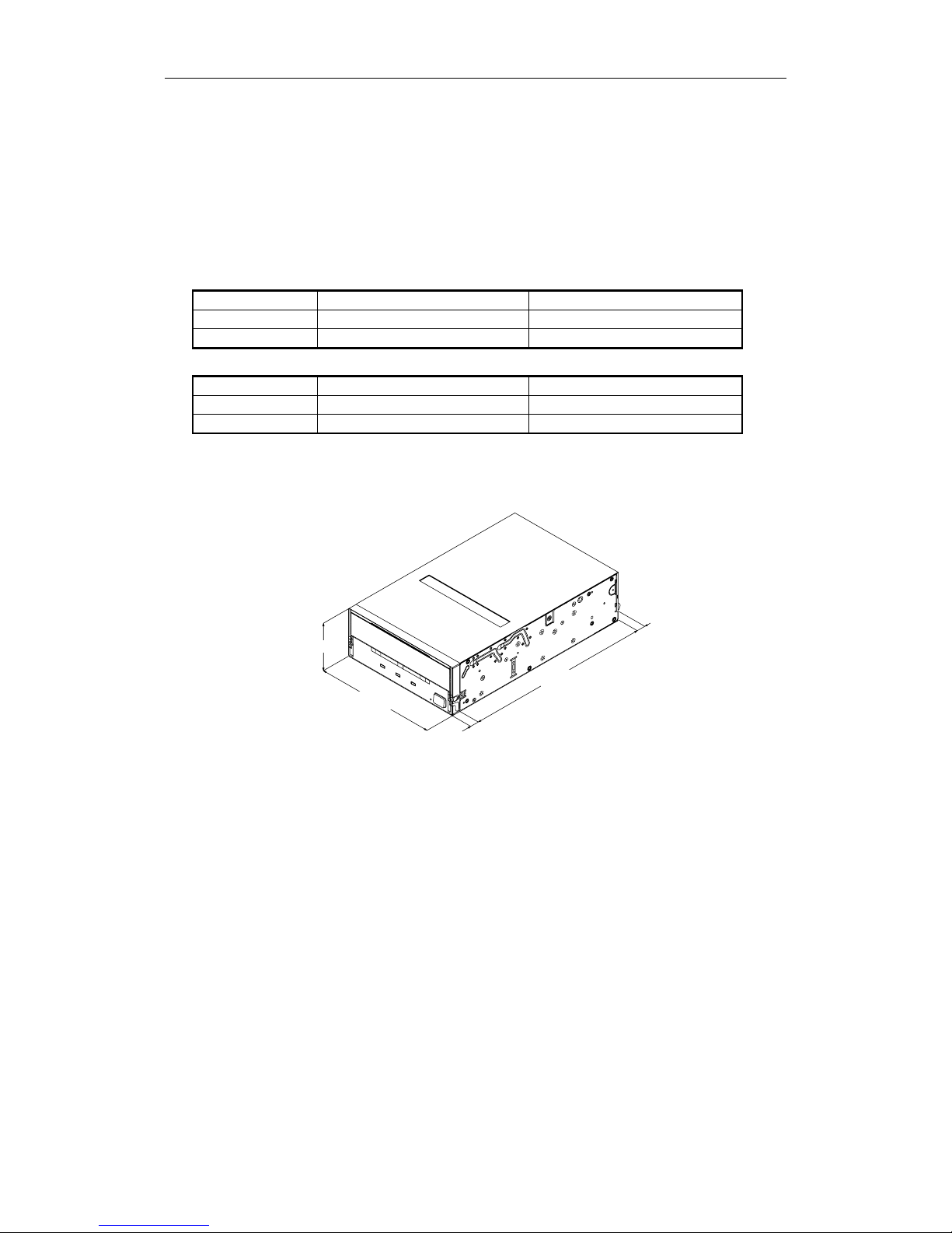
2.1.1. Dimensions
The SDX-570V/P
Height 41.2 mm (1.62 in) ± 0.5 mm (0.02 in)
Width 101.6 mm (4.00 in) ± 0.5 mm (0.02 in)
Depth 155.0 mm (6.10 in) ± 0.5 mm (0.02 in)
The SDX-570V/RP
Height 41.2 mm (1.62 in) ± 0.5 mm (0.02 in)
Width 146.0 mm (5.75 in) ± 0.5 mm (0.02 in)
Depth 155.0 mm (6.10 in) ± 0.5 mm (0.02 in)
Note: The above dimensions do not include the front panel thickness, eject button and Serial ATA connector.
Figure 2-1: Dimensions (SDX-570V)
Height 41.2 0.5mm
[1.62" 0.02"]
Width 101.6 0.5mm
[4.00" 0.02"]
Depth 155.0 0.5mm
[6.10" 0.02"]
8.3
0.5mm
[0.33" 0.02"]
+
_
+
_
+
_
+
_
+
_
+
_
+
_
+
_
7.4 0.6mm
[0.29" 0.02"]
+
_
+
_
2. Specification
SONY AIT-2 Turbo drive SDX-570V series Ver.1.0 2-2
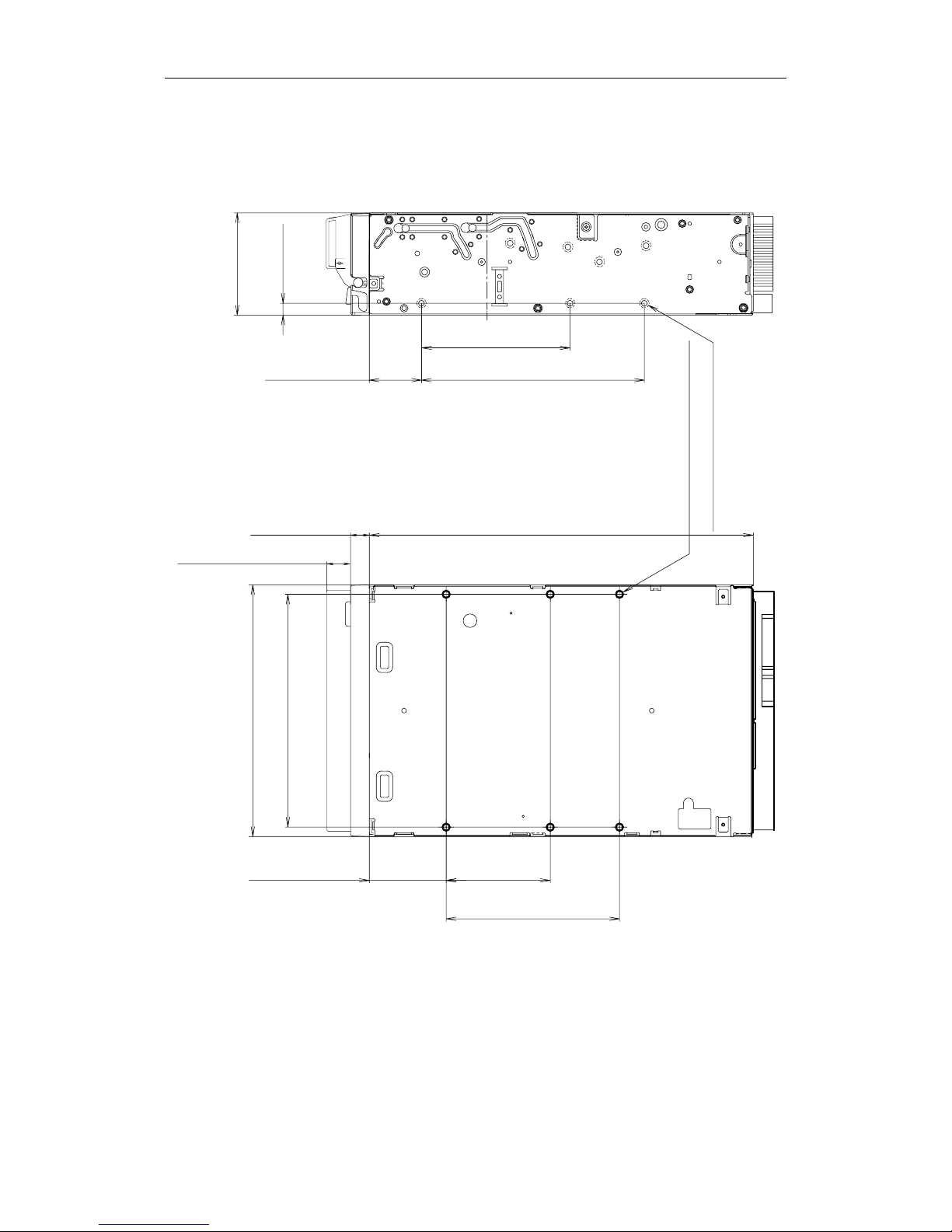
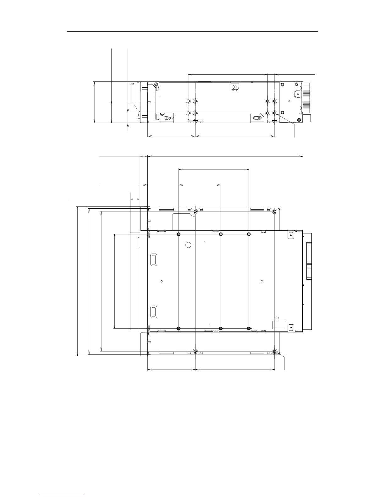
2.1.1.1. Mounting Holes
Figure 2-2a gives details of the mounting holes for the Sony SDX-570V/P and figure 2-2b for the Sony
SDX-570V/RP.
Figure 2-2a: SDX-570V/P Mounting Holes
155.0 0.5mm [6.10" 0.02"]
90.0 0.3mm [3.54" 0.01"]
60.0 0.3mm
[2.36" 0.01"]
70.0 0.3mm [2.76" 0.01"]
31.0 0.3mm
[1.22" 0.01"]
21.0 0.3mm
[0.83" 0.01"]
41.2 0.5mm
[1.62" 0.02"]
4.8 0.5mm
[0.19" 0.02"]
6-M3 (depth 2.5mm [0.10"] max.)
6-M3 (depth 2.5mm [0.10"] max.)
42.0 0.3mm
[1.65" 0.01"]
94.0 0.5mm [3.70" 0.02"]
101.6 0.5mm [4.00" 0.02"]
+
_
+
_
+
_
+
_
+
_
+
_
+
_
+
_
+
_
+
_
+
_
+
_
+
_
+
_
+
_
7.4 0.6mm
[0.29" 0.02"]
+
_
+
_
+
_
+
_
+
_
+
_
+
_
+
_
+
_
9.8 0.6mm [0.39" 0.02"]
+
_
+
_
2. Specification
SONY AIT-2 Turbo drive SDX-570V series Ver.1.0 2-3
Figure 2-2b: SDX-570V/RP Mounting Holes
79.2 0.3mm [3.12" 0.01"]
79.2 0.3mm [3.12" 0.01"]
47.5 0.3mm
[1.87" 0.01"]
79.2 0.3mm [3.12" 0.01"]
47.5 0.3mm
[1.87" 0.01"]
94.0 0.5mm [3.70" 0.02"]
21.8 0.5mm
[0.86" 0.02"]
41.2 0.5mm
[1.62" 0.02"]
9.9 0.5mm
[0.39" 0.02"]
139.6 0.5mm [5.50" 0.02"]
146.0 0.5mm [5.75" 0.02"]
149.0 0.5mm [5.87" 0.02"]
155.0 0.5mm [6.10" 0.02"]
7.6mm [0.3"]
70.0 0.3mm [2.76" 0.01"]
31.0 0.3mm
[1.22" 0.01"]
42.0 0.3mm
[1.65" 0.01"]
4-M3
6-M3
+
_
+
_
+
_
+
_
+
_
+
_
+
_
+
_
+
_
+
_
7.0 0.5mm
[0.28" 0.02"]
+
_
+
_
+
_
+
_
+
_
+
_
+
_
+
_
+
_
+
_
+
_
+
_
+
_
+
_
+
_
+
_
+
_
+
_
+
_
+
_
+
_
+
_
+
_
+
_
7.4 0.6mm
[0.29" 0.02"]
+
_
+
_
9.8 0.6mm
[0.39" 0.02"]
+
_
+
_
2. Specification
SONY AIT-2 Turbo drive SDX-570V series Ver.1.0 2-4
2.1.2. Weight
SDX-570V/P 780 grams, without a cassette and a front bezel.
SDX-570V/RP 1050 grams, without a cassette and a front bezel.
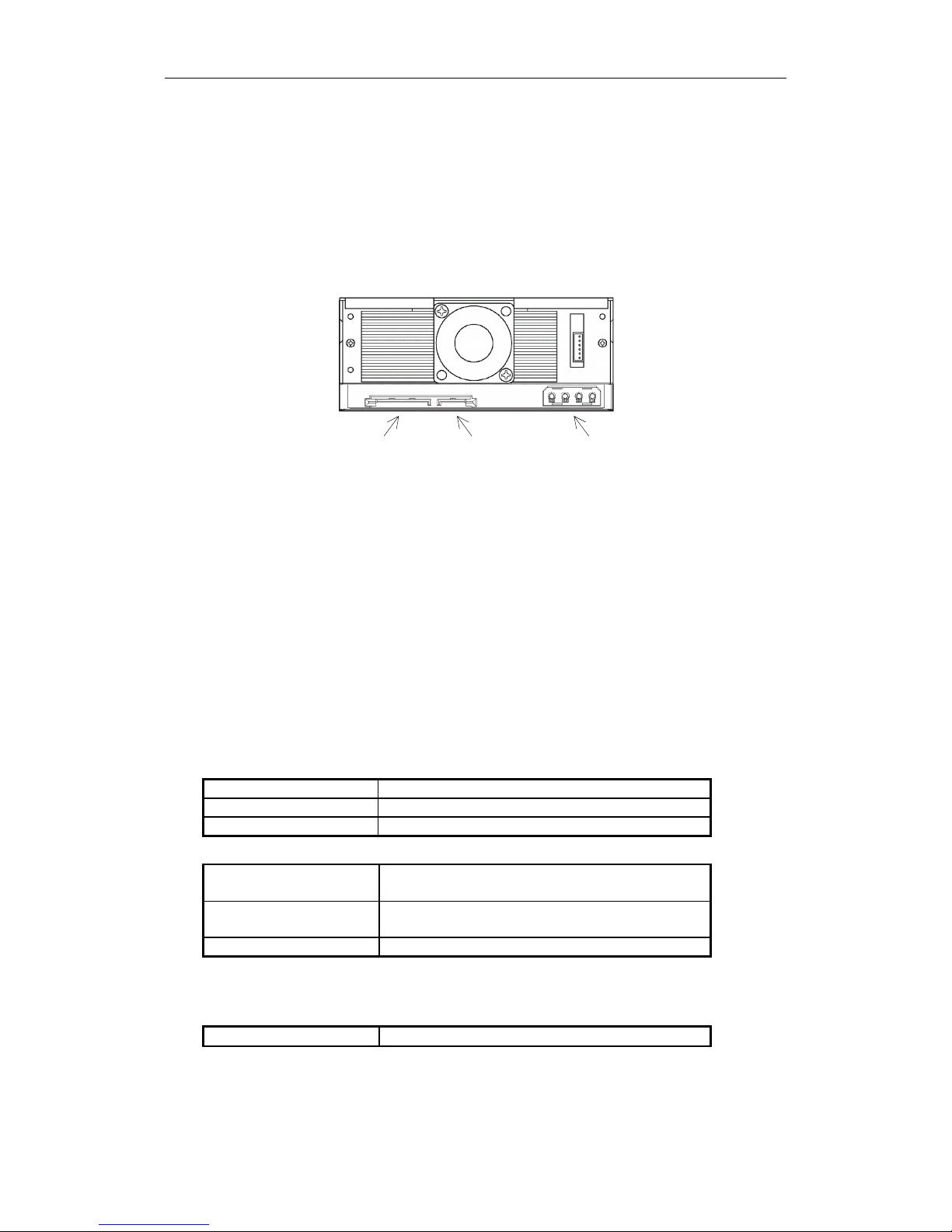
2.1.3. Connectors
The SDX-570V has a Serial ATA connector with a power connectors and signal connector at the positions shown in
Figure 2-3. All other connectors are for use by Sony’s manufacturing and service facilities only.
Figure 2-3: Connector Positions
2.1.3.1. Serial ATA Cables
Serial ATA configuration are supported by SDX-570V.
The hardware specification of this interface can be found in 6.3 Cables and connectors specifications of the Serial
ATA/High Speed Serialized AT Attachment Revision 1.0a.
2.2. Environmental Specifications
The specifications which apply when media is present may be different than these.
2.2.1. Temperature and Humidity Range
Temperature
Operating 5 °C to 40 °C (∆T < 10 °C/h)
Non-Operating (mech.) -40 °C to 70 °C (∆T < 20 °C/h)
Non-Operating (tape) -40 °C to 45 °C (∆T < 20 °C/h)
Humidity
Operating 20 to 80% RH, non-condensing
Maximum wet bulb temperature: 26 °C
Non-operating (mech.) 5 to 95%RH (∆RH<30%/h)
Maximum wet bulb temperature: 45 °C
Non-operating (tape) 20 to 80%RH (∆RH<30%/h)
Note: Please keep cool the drive's heatsink.
2.2.2. Altitude
Operating 0 to 10,000 feet
SATA
Power Connector
SATA
Signal Connector
Legacy
Power Connecto
r
2. Specification
SONY AIT-2 Turbo drive SDX-570V series Ver.1.0
2-5
2.2.3. Suspended Particulate
Operating
Less than 150 microgram/m
3
Based Sampling period 24 hours
2.2.4. Vibration
Operating Swept Sine 5 to 500Hz, @0.25G Peak 1 Octave/min.
3 axis, 3 directions
Non-operating Swept Sine 5 to 500Hz, @ 0.5G Peak 1 Octave/min.
3 axis, 3 directions
2.2.5. Shock
Operating No Data Loss
Half Sine
Performance
5 G Peak 3 ms
3 axes, 3 directions
*Interval 10 seconds
Non-operating No Device Damage
Half Sine
90 G Peak 3 ms
(30 G Peak 11 ms)
3 axes, 3 directions
*
Interval 10 seconds
2.2.6. Acoustic Noise
The ambient noise level is no greater than 25 dB (A). The sound-meter on (A) scale is located 1m in front of the
center of the drive front panel. (A): A curve weight
Streaming Write/Read 35dB (A)
Insert/Eject 60dB (A)
2.2.7. ESD
Front Panel Only, Integrated
product
Discharge Voltage
Less than 15kV: No operation failure
Less than 20kV: No drive damage
2.2.8. EMI
Radiated Emissions/
Conducted noise Emissions
EN55022/94_Class B+A1+A2
2. Specification
SONY AIT-2 Turbo drive SDX-570V series Ver.1.0 2-6
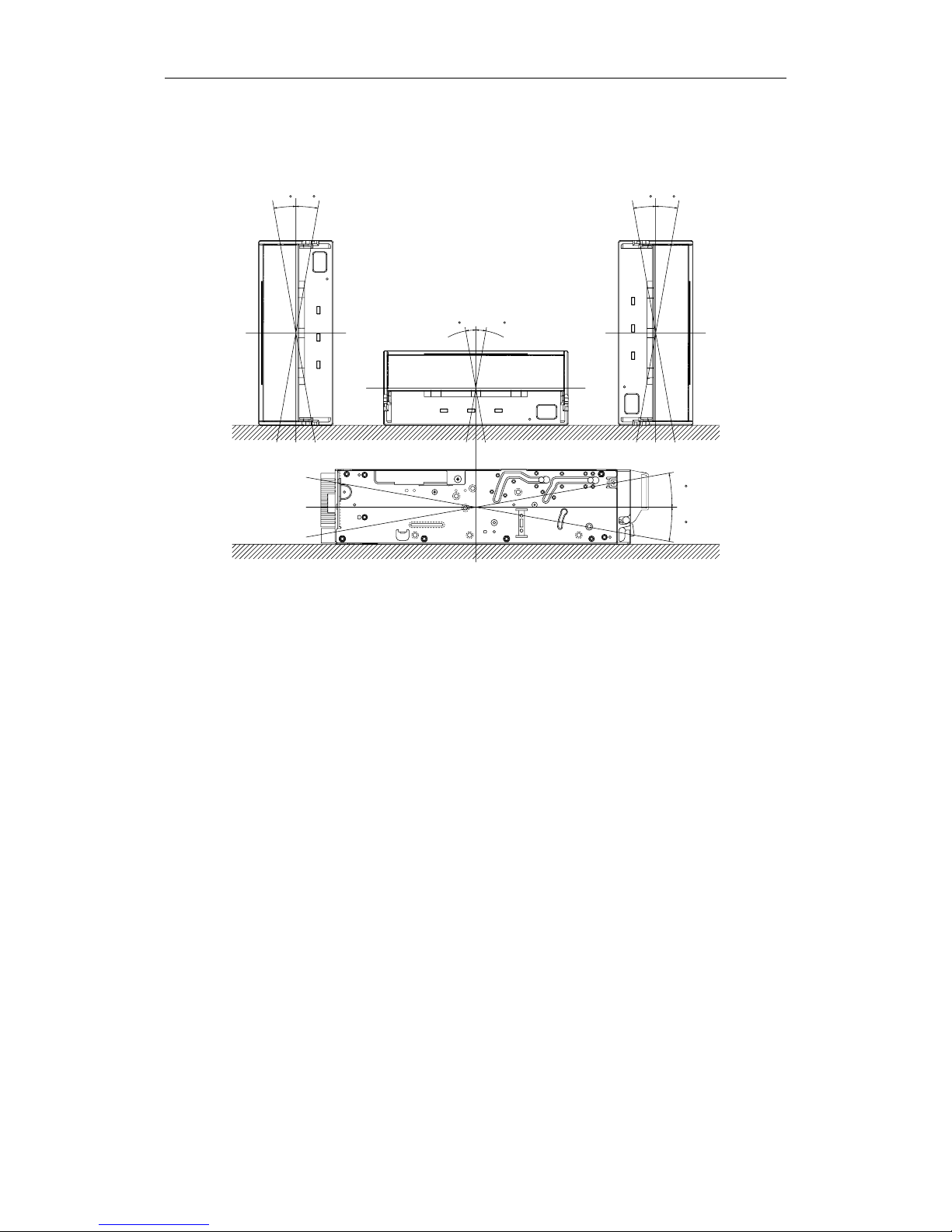
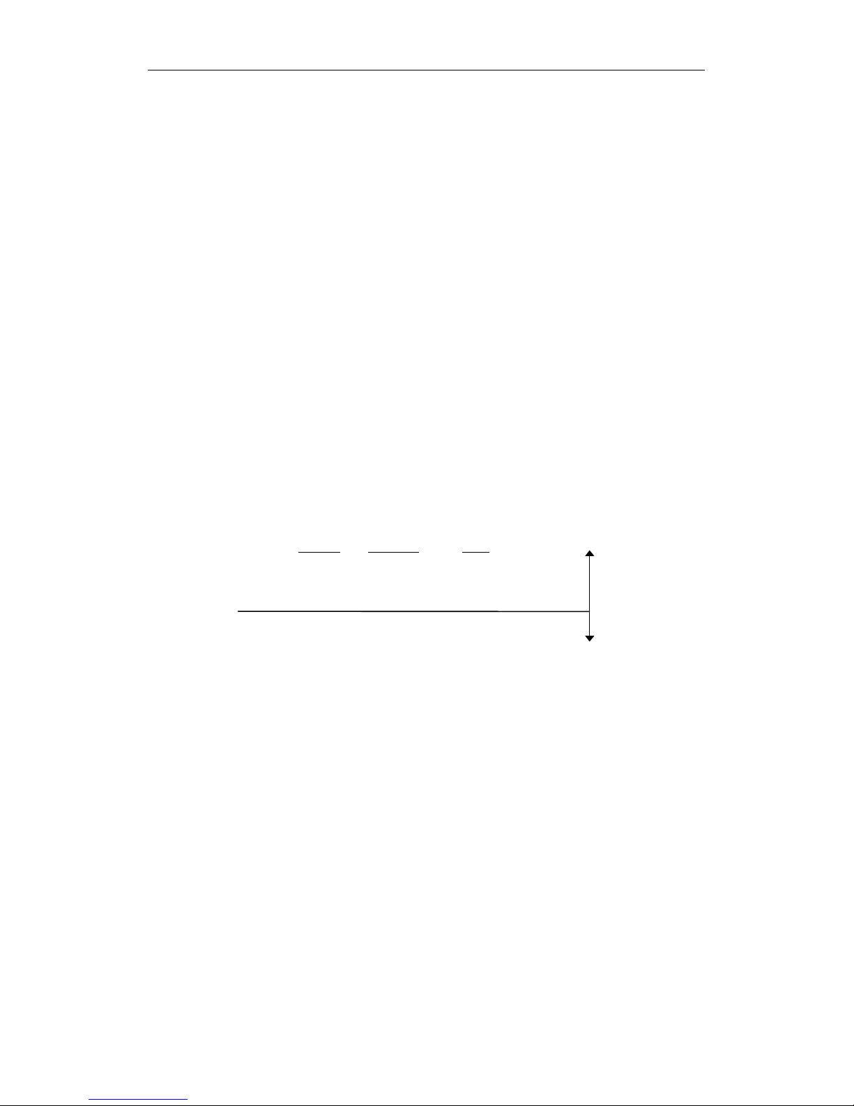
2.2.9. Orientation
The SDX-570V can be installed in three different mounting positions as shown in the figure below. Each position has
a maximum tolerance of ±10 degrees.
Figure 2-4: Mounting Attitude and Tolerance
2.3. Performance Specification
The data capacity, data transfer rate and data reliability specifications this chapter require the media to conform to
the AIT-E Turbo, AIT-1 Turbo and AIT-1 Media Specification and also require the drive and media to remain within
their respective operating and non-operating environmental specifications. The specifications below also assume
that the C3 ECC frame is generated on writing and used as necessary on reading, and further assumes that
read-after-write rewrites are used as necessary on writing.
10
10
10
10
10
10
10
10

2. Specification
SONY AIT-2 Turbo drive SDX-570V series Ver.1.0 2-7
2.3.1. Data Capacity
The SDX-570V includes a data compression capability. When data compression is enabled the drive capacity can
increase from 2 times to 3 times. The efficiency of the data compression depends on the actual data that is being
compressed and cannot be predicted precisely prior to compression.
Format AIT-E Turbo Standard Format
Native
Capacity
20.0 Gbyte typical When using 98 meter tape AIT-E Turbo cassette (TAITE-20N)
Format AIT-1 Standard Format
25.0 Gbyte typical When using 170 meter tape AIT-1 cassette (SDX1-25C)
Native
Capacity
35.0 Gbyte typical When using 230 meter tape AIT-1 cassette (SDX1-35C)
Format AIT-1 Turbo Standard Format
Native
Capacity
40.0 Gbyte typical
When using 186 meter tape AIT-1 Turbo cassette (TAIT1-40N and
TAIT1-40C)
Format AIT-2 Standard Format
50.0 Gbyte typical When using 230 meter tape AIT-2 cassette (SDX2-50C)
Native
Capacity
36.0 Gbyte typical When using 170 meter tape AIT-2 cassette (SDX2-36C)
Format AIT-2 Turbo Standard Format
Native
Capacity
80.0 Gbyte typical
When using 186 meter tape AIT-2 Turbo cassette (TAIT2-80N and
TAIT2-80C)
2.3.2. Data transfer Rate
2.3.2.1. Sustained Data Transfer Rate to and from Tape
The sustained transfer rate to and from the tape is 12 Mbyte per second with AIT-E Turbo, AIT-1 Turbo, AIT-2, AIT-2
Turbo cassette. The sustained transfer rate to and from the tape is 8 Mbyte per second with AIT-1 cassette. For this
sustained rate to be achieved, the drive must be streaming. There may be some dependency on the host and
application softwares for this to be achieved.
2.3.2.2. Burst Transfer Rate to and from the Serial ATA
The SDX-570V will transmit and receive data bursts to and from the Serial ATA at a maximum burst rate of 150
Mbyte per second.
2.3.3. Initialize Time
Initialize Time means the period from the time the drive is powered on to the time when the drive is ready and waiting
for a ATA/ATAPI command such as INQUIRY or TEST UNIT READY. Initialize Time is less than 5 seconds.
The drive will respond with BUSY status until the completion of the Initialize Time. The Initialize Time does not
include the time necessary for drive diagnostics to complete and the drive to become ready for tape insertion.
2. Specification
SONY AIT-2 Turbo drive SDX-570V series Ver.1.0 2-8
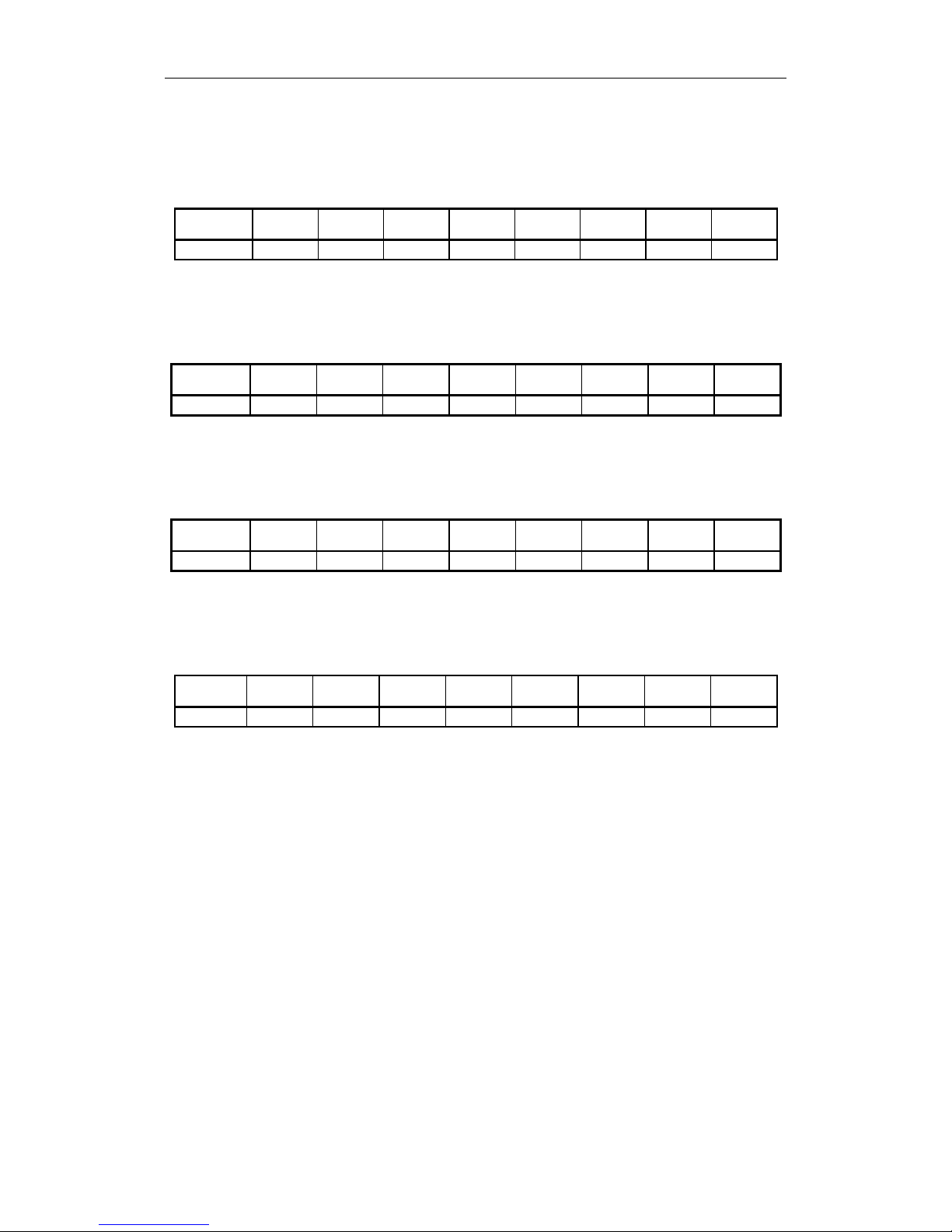
2.3.4. Load Time
Load Time means the period from the time when the operator inserts a cassette into the drive to the time when the
drive is ready. The data in the below table represents the average time for SDX-570V. The time it may take for
retrying is not reflected here.
TAITE-20N
(98m)
SDX1-25C
(170m)
SDX1-35C
(230m)
TAIT1-40N
(186m)
TAIT1-40C
(186m)
SDX2-50C
(230m)
TAIT2-80N
(186m)
TAIT2-80C
(186m)
Load Time 80 sec 14 sec 14 sec 80 sec 14 sec 14 sec 25 sec 14 sec
2.3.5. Unload Time
Unload Time means the period from the beginning of the unload sequence caused by Unload Command or Eject
button to the time when a cassette is ejected from the slot. Unload Time does not include Rewind time. The data in
the below table represents the average time for SDX-570V. The time it may take for retrying is not reflected here.
TAITE-20N
(98m)
SDX1-25C
(170m)
SDX1-35C
(230m)
TAIT1-40N
(186m)
TAIT1-40C
(186m)
SDX2-50C
(230m)
TAIT2-80N
(186m)
TAIT2-80C
(186m)
Unload Time 25 sec 20 sec 20 sec 25 sec 20 sec 20 sec 25 sec 20 sec
2.3.6. Search Time
Search Time means the period for the drive to find the position that is required by a command. This time also
depends on the tape length and the position of the head along the tape. The data in the below table represents the
average time for SDX-570V. The time it may take for retrying is not reflected here.
TAITE-20N
(98m)
SDX1-25C
(170m)
SDX1-35C
(230m)
TAIT1-40N
(186m)
TAIT1-40C
(186m)
SDX2-50C
(230m)
TAIT2-80N
(186m)
TAIT2-80C
(186m)
Search Time 60 sec 85 sec 120 sec 105 sec 80 sec 120 sec 105 sec 80 sec
2.3.7. Rewind Time
Rewind Time means the period from the beginning to the end of rewinding sequence. This value depends on the
tape length and the position of the head along the tape. The data in the below table represents the average time for
SDX-570V. The time it may take for retrying is not reflected here.
TAITE-20N
(98m)
SDX1-25C
(170m)
SDX1-35C
(230m)
TAIT1-40N
(186m)
TAIT1-40C
(186m)
SDX2-50C
(230m)
TAIT2-80N
(186m)
TAIT2-80C
(186m)
Rewind Time 55 sec 80 sec 105 sec 90 sec 90 sec 105 sec 90 sec 90 sec
2.3.8. Error Rate
The un-correctable bit error rate is expected to be less than 1 in 10 to the 17th.
2.3.9. Retry Limits on Rewrites
For Read-after-Write error correction, each frame can be rewritten up to a maximum of 63 times giving 64 writes of
the frame.
2.3.10. Definition of Failure
A failure is defined as any permanent manufacture of the drive that prevents the user from retrieving data from tape.
This includes failure to power up, failure to unload or eject a cassette, or failure to write and read data to and from the
tape, providing that both the drive and tape are being used within specification.
Faults are not considered failures when they are related to operator error mishandling and abuse, system-related
faults (cabling problems unsupported systems, operating software and so on) no trouble found, and transportation
damage.
2. Specification
SONY AIT-2 Turbo drive SDX-570V series Ver.1.0
2-9
2.3.11. Mean Time Between Failures
The Mean Time Between Failures (MTBF) for the SDX-570V is 300,000 power-on hours, assuming a duty cycle of
100%, where:
2.3.12. Mean Time to Repair
The Mean Time To Repair (MTTR) of the SDX-570V is 30 minutes. Since at the field level the entire drive is
considered a Field Replaceable Unit (FRU) the time to replace the drive with a new one is less that 30 minutes.
2.3.13. Component Life
The specified life of the SDX-570V is 5 years average.
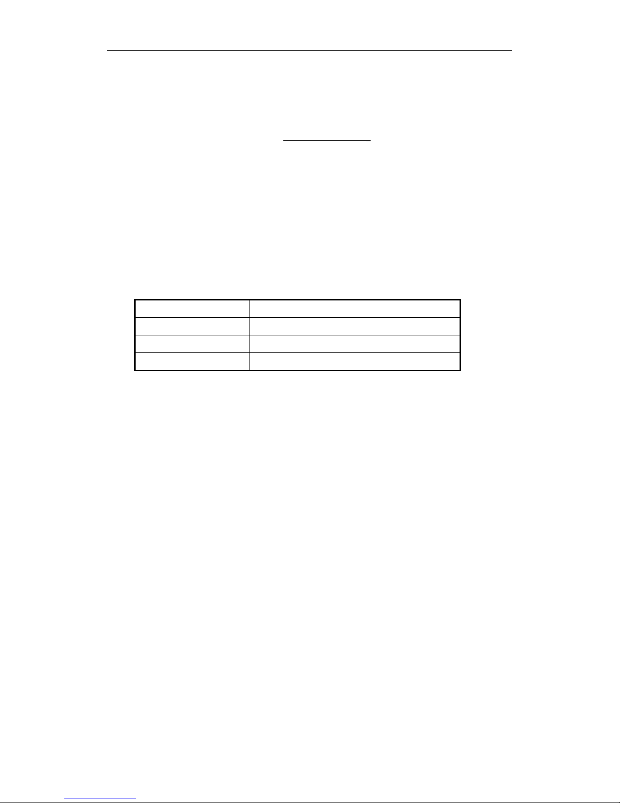
2.3.14. Durability
The durability of the components in the SDX-570V will exceed the number of operations listed on the following table:
Start/Stop 400,000 times
Reposition 3,000,000 times
Thread/Unthread 100,000 times
Load/Eject 100,000 times
2.4. Safety
The SDX-570V conforms to the following safety Standards:
• UL/cUL (Underwriters Laboratories, Inc.)
UL 60950-1, First Edition/CSA C22.2 No. 60950-1-03
Safety of Information Technology Equipment.
• TUV
EN 60950-1:2001 Safety of Information Technology Equipment including
Electrical Business Equipment
• CE Mark
2.4.1. Conditions of Acceptability
The SDX-570V is for use only in equipment where the suitability of the combination has been determined by an
appropriate certification organization (for example, Underwriters Laboratories, Inc. or the Canadian Standards
Association in North America, and the British Standards Institution or Verband Deutscher Elektrotechniker in
Europe). Other considerations include the following:
1. An enclosure must be supplied to limit the operator’s access to live parts, to provide system stability, and to
furnish the drive with the necessary grounding integrity.
2. The necessary voltage supplies must be provided. These supplies are Extra Low Voltage SEC for UL and CSA,
or Safety Extra Low Voltage for BSI, VDE, and so on, of +5V and +12V DC.
2.5. Installation Requirements
Note: Do not move the drive while it is operating. It may cause malfunction.
D
utyCycle = ×100
Tape Motion Time
P
owerOn Time
2. Specification
SONY AIT-2 Turbo drive SDX-570V series Ver.1.0 2-10
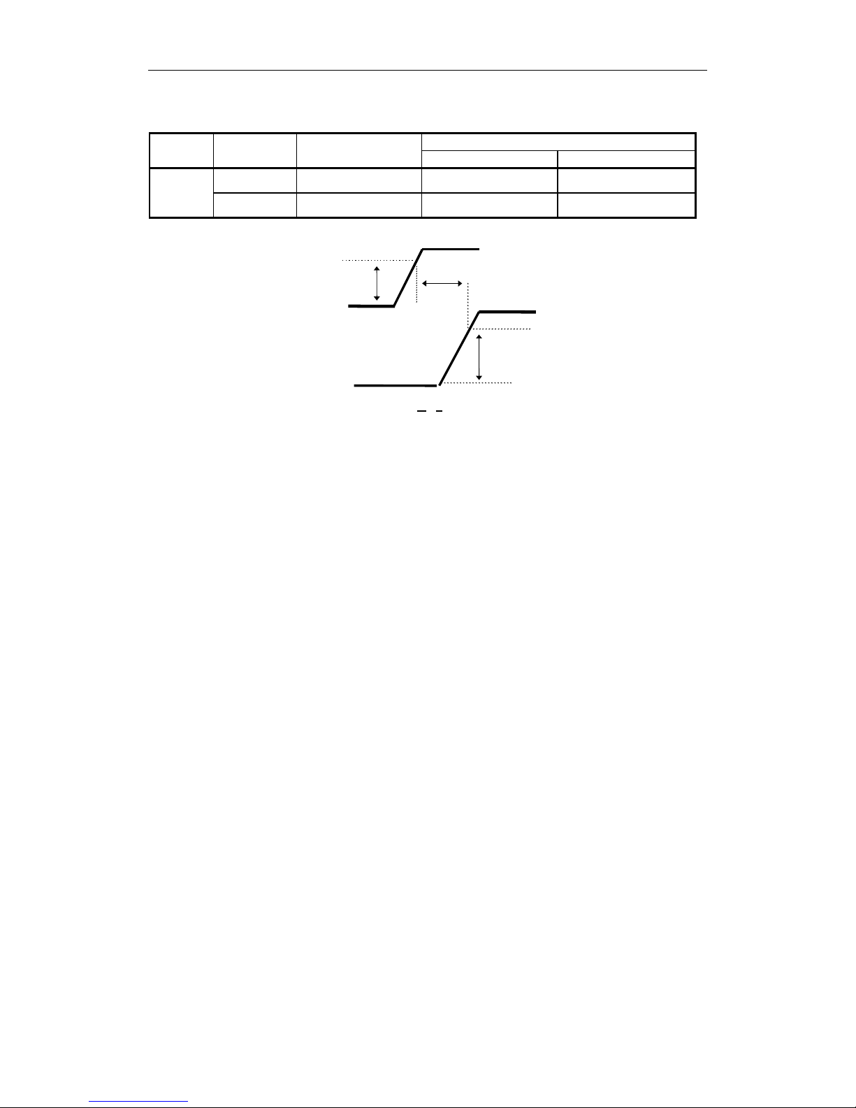
2.5.1. Power Requirements
Current
Voltage Max Ripple
Typical Maximum
5V ± 5% 100 mV p-p 1.4A 1.7A
SDX-570V
12V ± 10% 150 mV p-p 0.5A 1.3A
4.75V
T
10.8V
5V
12V
-300 ms <
T < 300 ms
Figure 2-5: Power-up Sequence
Note: Voltage has to increase constantly during Power-up until Maximum is reached.
Do not turn off the drive while the tape is in the drive.
2.6. Data Compression
The tape capacity is increased by compressing data prior to writing it to the tape. Data compression is a well
established technology for reducing the number of bits used to represent data in order to improve data transfer rate
as well as reduce the amount of storage space consumed by the data. The compression ratio depends on the source
file type. The SDX-570V uses the ALDC Data Compression algorithm. ALDC is ECMA standard data compression
algorithm. (ECMA-222) The Data Compression control page allows the host computer to enable data compression
and decompression and also configure the way in which the drive responds to compressed/uncompressed data
boundaries on the tape. The AIT-E Turbo, AIT-1 Turbo, AIT-1, AIT-2 Turbo and AIT-2 Format allows both
compressed and uncompressed data to reside on the same tape.
The Sony SDX-570V has a DIP switch to disable the Data Compression/ Decompression. After power-on reset with
this DIP switch set, both data compression and data decompression are disabled However, a MODE SELECT
command can override the setting of this DIP switch. After power-on reset without this DIP switch set, both data
compression and data decompression are enabled. (See clause 3.1.5)
3. Installation
SONY AIT-2 Turbo drive SDX-570V series Ver.1.0 3-1
3. Installation
3.1. Installation Guide
This Product Specification Manual is applicable for SDX-570V drive.
Dip switch
Figure 3-1: DIP switch
1 Drive Mode-1
2 Drive Mode-2
3 Drive Mode-3
4 Drive Mode-4
5 Reserved (OFF)
6 Periodic Cleaning Req (ON)
7 DC Control-1 (ON)
8 DC Control-2 (OFF)
Figure 3-2: DIP Switch positions
Table 3-1: Drive Mode
DIP SW 1 2 3 4 MODE
OFF OFF OFF OFF Normal
1 2 3 4 5 6 7 8
ON
OFF
3. Installation
SONY AIT-2 Turbo drive SDX-570V series Ver.1.0
3-2
Table 3-2: Periodic Cleaning Request (Refer to 4.5.1.2)
DIP SW 6 Definition
OFF Disable Periodic Cleaning Request
ON Enable Periodic Cleaning Request
3.1.1. Data Compression ON Switch
Data compression can be selected by DIP switch.
DC Control-1 DC Control-2 Definition
OFF OFF Compression disabled at power-on. The host is allowed to control
compression.
OFF ON Compression disabled at power-on. The host is not allowed to control
compression.
ON OFF Compression enabled at power-on. The host is allowed to control
compression.
ON ON Compression enabled at power-on. The host is not allowed to control
compression.
Figure 3-3: Data Compression Switches
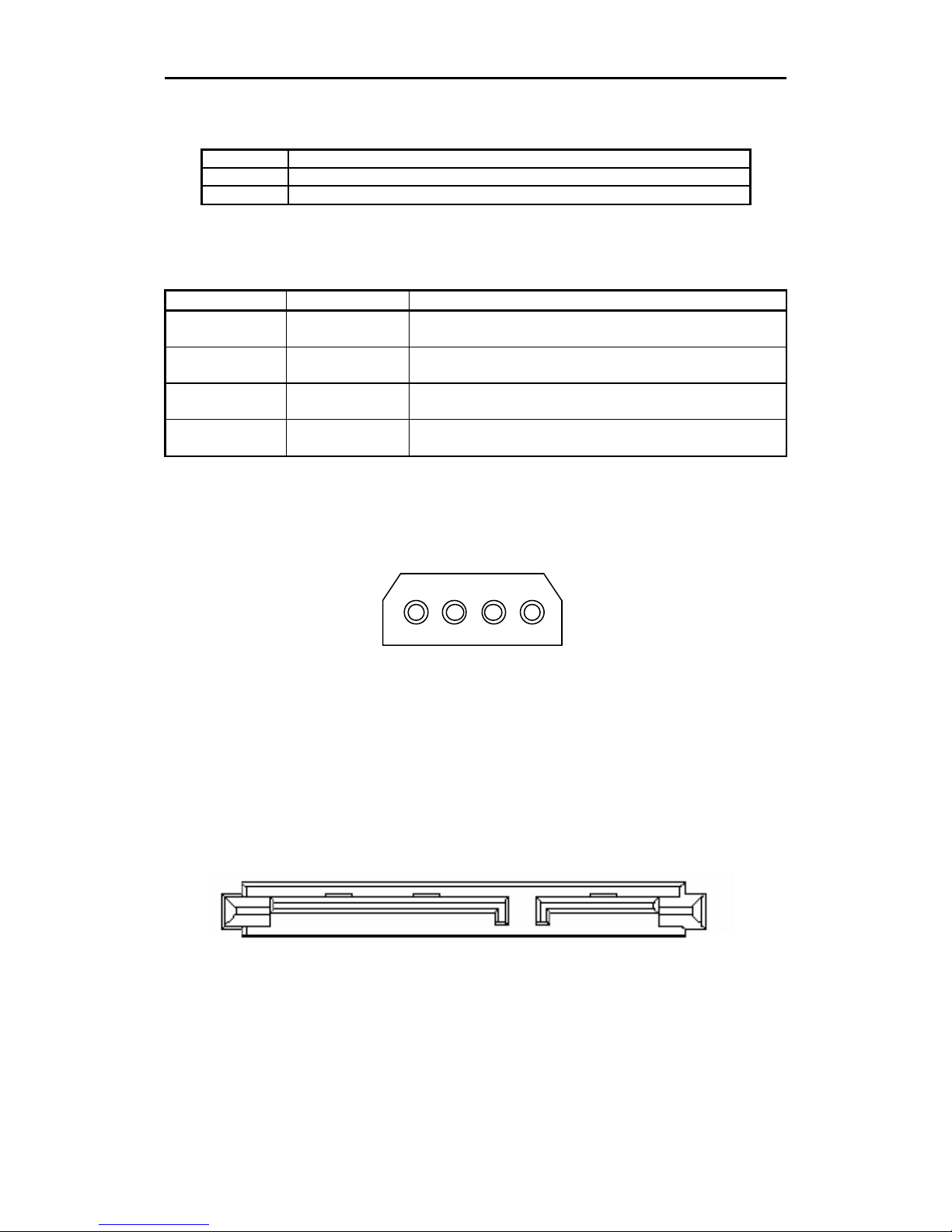
3.1.2. Legacy Power Connector
The Legacy power connector is illustrated as Figure 3-4.
5V GND GND 12V
4 3 2 1
Figure 3-4: Legacy Power Connector
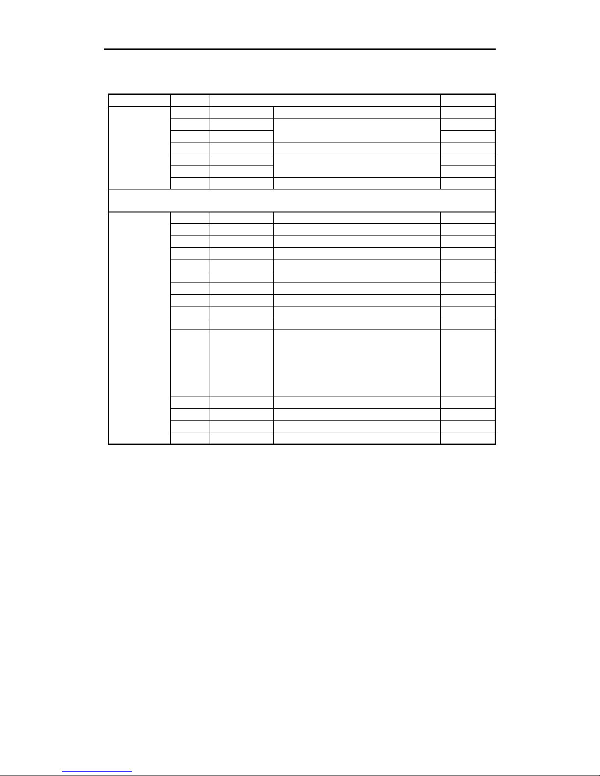
3.1.3. SATA Interface Connectors
Figure 3-5 illustrates SATA Signal/Power connectors and table 3-3 shows the assignments for the pins of the
connectors.
Figure 3-5: SATA Interface Connectors
Caution!: DO NOT USE both power connections (Legacy Power Connector and SATA Power Connector) at the
same time. Doing so will result in drive failure.
Pin
P15
Pin
P1
Pin
S7
Pin
S1
SATA Power Connector SATA Signal Connector
3. Installation
SONY AIT-2 Turbo drive SDX-570V series Ver.1.0
3-3
Table 3-3: SATA Interface connector pins
No. Plug Connector pin definition Signal
S1 GND 2nd mate Gnd
S2 A+ RX+
S3 A-
Differential signal A from Phy
RXS4 Gnd 2nd mate Gnd
S5 B- TXS6 B+
Differential signal B from Phy
TX+
Signal
S7 Gnd 2nd mate Gnd
Key and spacing separate signal and power
segments
P1 V33 3.3V power 3.3V
P2 V33 3.3V power 3.3V
P3 V33 3.3V power, pre-charge, 2nd Mate 3.3V
P4 Gnd 1st mate Gnd
P5 Gnd 2nd mate Gnd
P6 Gnd 2nd mate Gnd
P7 V5 5V power, pre-charge, 2nd Mate 5V
P8 V5 5V power 5V
P9 V5 5V power 5V
P10 Gnd 2nd mate Gnd
P11 Reserved 1. This pin corresponding to P11 in the
backplane receptacle connector is also
reserved
2. The corresponding pin to be mated with
P11 in the power cable receptacle
connector shall always be grounded
Reserve
P12 Gnd 1st mate Gnd
P13 V12 12V power, pre-chage, 2nd mate V12
P14 V12 12V power V12
Power
P15 V12 12V power V12
3. Installation
SONY AIT-2 Turbo drive SDX-570V series Ver.1.0
3-4
3.1.4. Attaching and Removing the Dust Cover
3.1.4.1. Attaching the Dust Cover
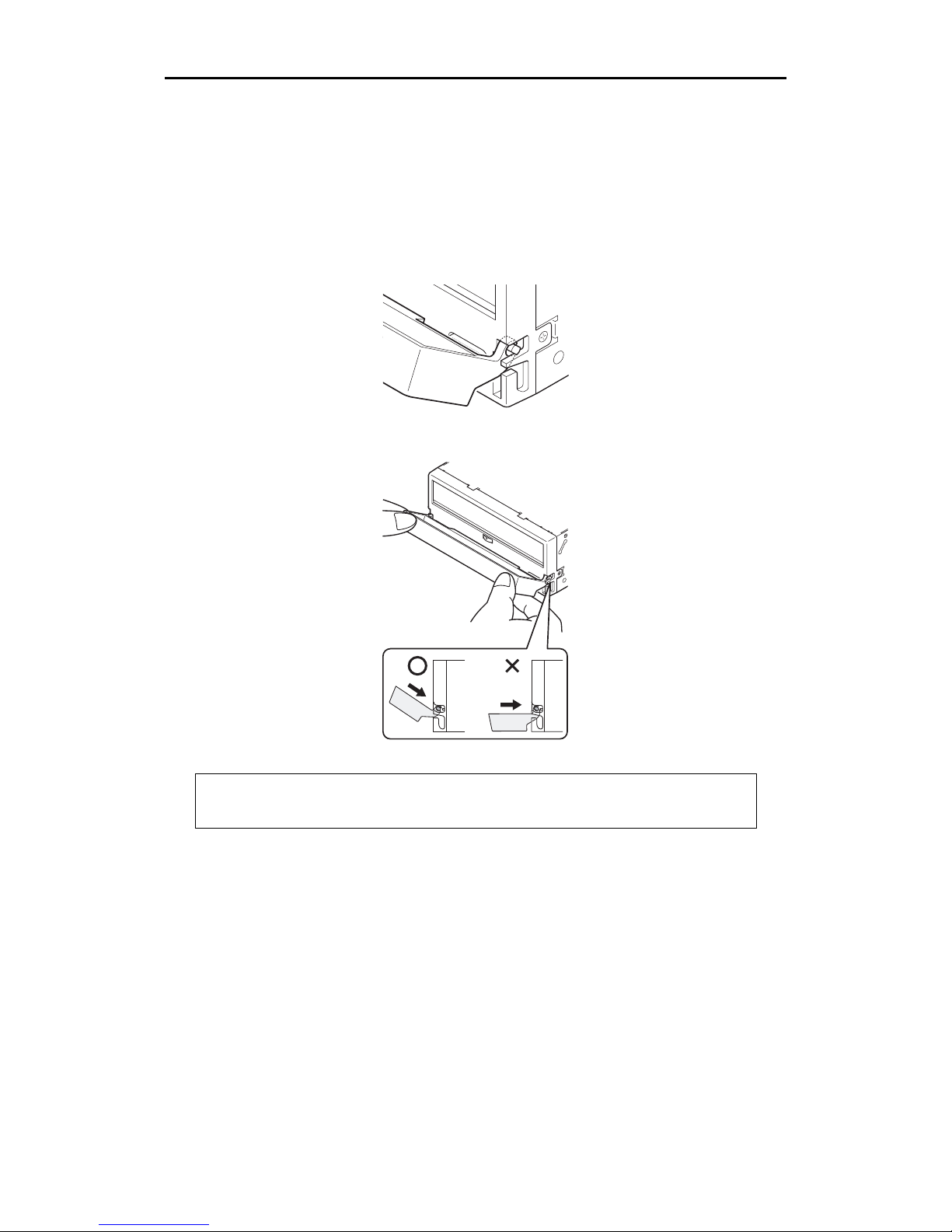
(1) Align the dust cover’s hinge clips (one on each side) with the pins of the drive bezel.
• The dust cover should be positioned so that the six magnets on the cover’s back face the drive bezel.
• Holding the dust cover at an angle as shown in the figure below, set the hinge clips on top of the bezel pins,
positioning them so that they bracket the pins.
(2) Press down at an angle on each side in turn until you hear the hinge clips click into place.
Caution:
Do not press the dust cover in horizontally from the side. Doing so could cause the dust cover to break.
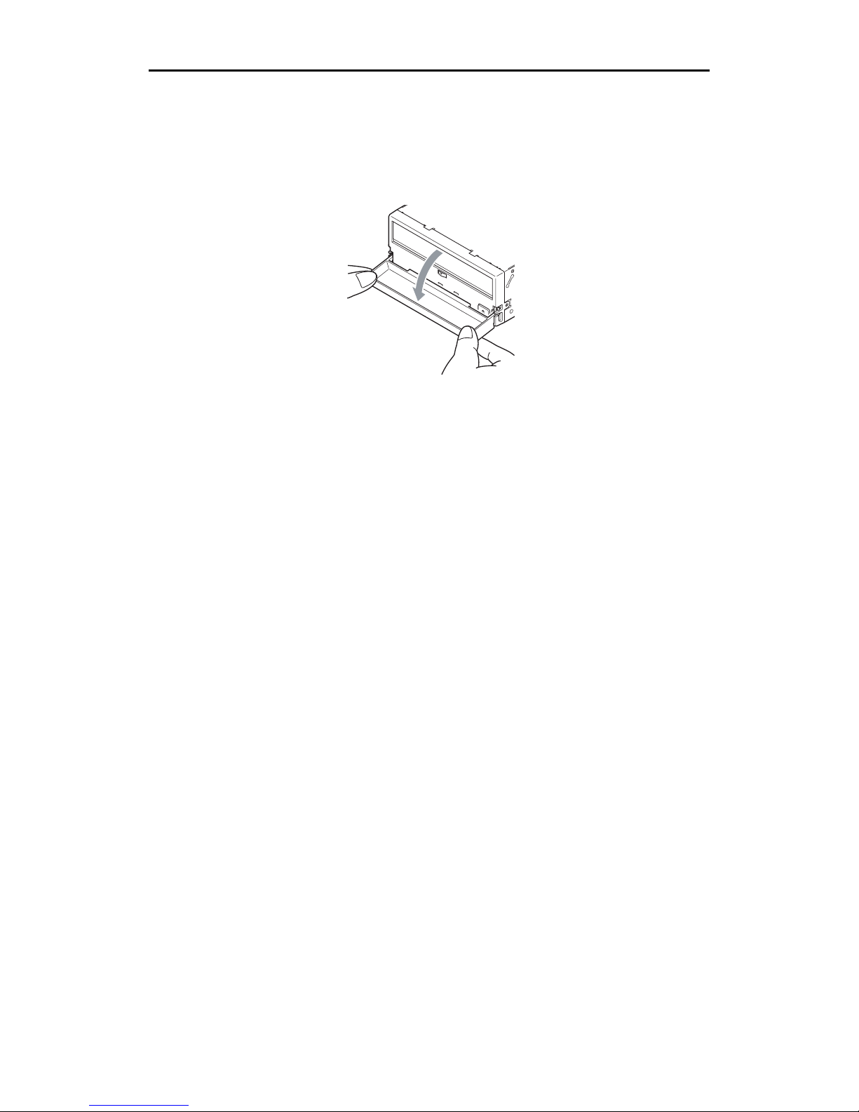
(3) Close the dust cover.
This completes attachment of the dust cover.
3. Installation
SONY AIT-2 Turbo drive SDX-570V series Ver.1.0
3-5
3.1.4.2. Removing the Dust Cover
(1) Open the dust cover.
(2) Holding the dust cover at both corners, carefully raise the dust cover.
The dust cover hinge clips and drive bezel pins uncouple.

3. Installation
SONY AIT-2 Turbo drive SDX-570V series Ver.1.0
3-6
This page intentionally left blank.
4. Operation
SONY AIT-2 Turbo drive SDX-570V series Ver.1.0 4-1
4. Operation
4.1. Summary of LED Indications
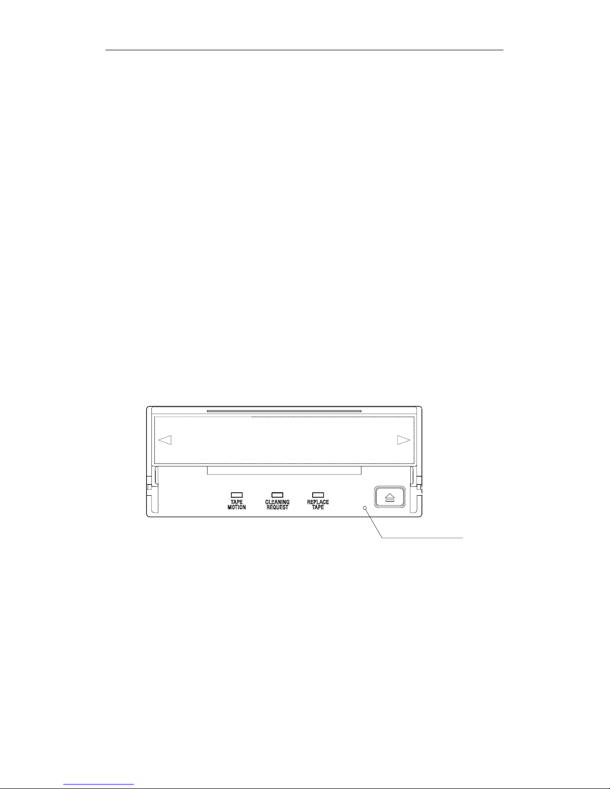
The SDX-570V have 3 LEDs. Each LED shows "Tape Motion", "Cleaning Request", and "Replace Tape" as defined.
"Tape Motion" to show the tape motion in the drive.
"Cleaning Request" to be on, when CLEANING is required.
"Replace Tape" to be on, when the tape needs to be replaced. It should be on when a medium error occurred.
All of three LEDs flash fast simultaneously, when the drive is in malfunction.
The following table shows the meaning of each LED indications:
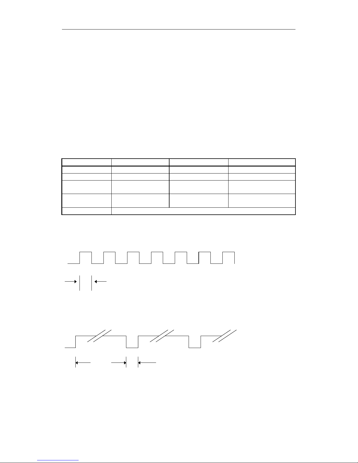
Table 4-1: Meaning of each LED indications
LED Tape Motion Cleaning Request Replace Tape
Off No Tape Cleaning is Not Necessary No Media Error Occurred
On Tape Loaded Cleaning Request Media Error Occurred
Flash Slowly Tape Access in Progress
(Write/Read)
Cleaning is Not Completed
Flash Fast Tape Access in Progress
(Others)
All LED Flash Fast H/w Error Occurred
Flash Fast (0.3sec on/0.3sec off)
0.3 sec
Flash Slowly (0.9sec on/0.3sec off)
0.9sec
0.3sec
4. Operation
SONY AIT-2 Turbo drive SDX-570V series Ver.1.0 4-2
4.2. Operator Action
4.2.1. Powering Up the SDX-570V
After the initial installation of the SDX-570V has been verified, power can be applied to the unit. The +12V and +5V
power must be applied simultaneously. (See Figure 2-5) The SDX-570V will execute a power-up diagnostic and then
comes ready.
Once the tape has been loaded the SDX-570V sends a CHECK CONDITION response on receipt of the next
ATA/ATAPI command from the host. The UNIT ATTENTION key is set in the returned REQUEST SENSE data to
indicate that the tape may have been changed. (Sense Key/ASC/ASCQ=06/28/00)
4.2.2. Inserting Cassettes
The operator inserts a cassette into the slot on the front panel. As the cassette is inserted, the drive takes it and
automatically loads it into the drive mechanism. The SDX-570V performs a tape load sequence as described in
clause 4.3.1
4.2.3. Removing Cassettes
The cassette can be removed from the SDX-570V either in response to a ATA/ATAPI UNLOAD command, or by
pressing the Eject button. The operator uses the Eject button to initiate the unload sequence (see clause 4.3.2). The
mechanism winds the tape to Beginning of Media (BOM), unthreads it, and ejects the cassette from the slot.
Operation of the Eject button is disabled if the host has previously sent an ATA/ATAPI PREVENT ALLOW MEDIA
REMOVAL command with prevent bit set to one. In this case, pressing the Eject button has no effect, and does not
initiate an Unload sequence. The Eject button returns to normal operation following receipt of an PREVENT ALLOW
MEDIA REMOVAL command with prevent bit clear.
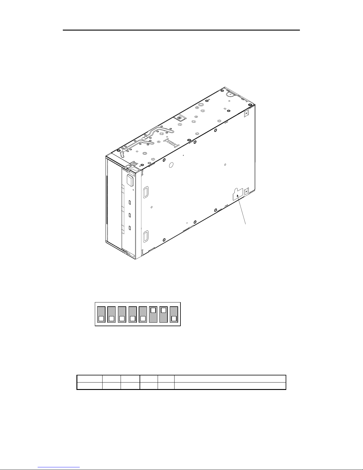
4.2.4. Hard Reset Hole
In case of emergency, you can immediately reset the drive itself by pushing the switch in the “Hard Reset Hole” with
the tip of a pin. However, there is a risk of losing data upon execution of this operation in the Write or Read mode.
The hardware reset operation is only for manufacturing and repair purposes.
Hard reset hole
4. Operation
SONY AIT-2 Turbo drive SDX-570V series Ver.1.0 4-3
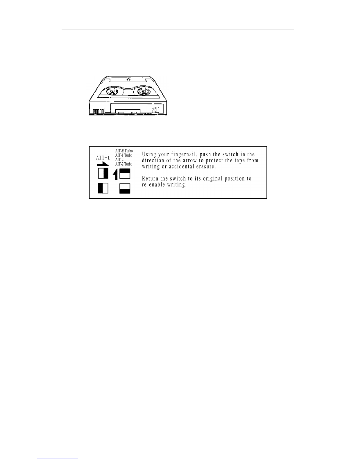
4.2.5. Write-Protecting Cassettes
Cassettes can be write-protected by sliding the tab on the back of the cassette open. In this state, data can be read
from the tape but not written to it.
Caution: The Tape Log, which contains a history of usage of the tape, will not be updated when the cassette is
write-protected. It follows that the Tape Log becomes inaccurate if a cassette is used write-protected, and the media
warning cannot be relied on to indicate that the cassette needs to be copied and replaced.
4.3. Internal Function
4.3.1. The Load Sequence
(Effective for SDX-T3N, TAITE-20N, TAIT1-40N and TAIT2-80N)
Refer to 14.2.1 Fast Media Load/Unload (Effective for SDX1-25C, SDX1-35C, TAIT1-40C and TAIT2-80C MIC
cassette)
During load sequence, the following occurs:
(1) The drive mechanism accepts the cassette and threads the tape. The tape is then moved to Beginning-of-Tape
(BOT) and the Reference area is checked to find the tape format. If the format is not AIT-1, the drive rewinds
the tape to BOT and awaits either a Write, Partitioning, Mode Select or an UNLOAD command.
(2) The System area is then accessed and the System log is read into the drive.
(3) Finally the drive goes on-line.
In the case of 2 partition tape the drive detects that the tape has been formatted as a two partition tape when the
Reference Area is read. The drive will then automatically position to the beginning of partition 0 before coming on
-line. Partition 0 is the partition that begins the furthest from BOM.
4.3.2. The Unload Sequence (Effective for SDX-T3N, TAITE-20N, TAIT1-40N and TAIT2-80N)
Refer to 14.2.1 Fast Media Load/Unload (Effective for SDX1-25C, SDX1-35C, TAIT1-40C and TAIT2-80C MIC
cassette)
The drive will always write any buffered data out to tape followed by an EOD prior to initiating the Unload sequence.
During this sequence the tape is rewound to BOT and, if the tape is write-enabled, the copy of the tape log held in
RAM is written back to tape. The tape is then rewound to BOM and the tape unthreaded from the mechanism. At this
stage the tape is either retained in the drive or ejected, depending on media removal is enabled by the Prevent Allow
Media Removal command.
In the case of two partition tape the drive detects that the tape has been formatted as a two partition tape when the
Reference Area is read during the load sequence. When the Unload operation begins the drive will then
automatically update the Tape Log for each partition before unloading the tape.
4. Operation
SONY AIT-2 Turbo drive SDX-570V series Ver.1.0 4-4
4.3.3. Power-Fail Handling
If there is a power-fail, the SDX-570V performs the following actions, and reverts to its default configuration:
(1) The drive remains positioned at the point where the power-fail.
(2) It executes the Power-Up sequence of self-tests. (When power is restored.)
(3) If a tape is in the drive, the SDX-570V starts a LOAD sequence. The drive rewinds the tape to BOT and remains
on-line.
(4) The drive returns CHECK CONDITION status for the first command after the power-fail or Reset. The next
command from the initiator should be a REQUEST SENSE. The drive will return sense data including a sense
key that will indicate that the drive has been reset. (Sense Key/ASC/ASCQ=06/29/00)
4.3.4. Diagnostic and Normal Status Displays
This chapter describes LED displays while the SDX-570V is starting up. When power is turned on, the SDX-570V will
go through its diagnostics to reach normal status. When a failure is detected during diagnostics, the LEDs show that
the SDX-570V is out of order and needs to be repaired.
Note: When power is turned on, the all LED on before the front panel test.
4.3.4.1. Diagnostic Status Display
The SDX-570V starts with its Diagnostic function. This is made up of the Front Panel Test and the Kernel Test.
Front Panel Test
LED display sequence:
This function is for checking TAPE MOTION, CLEANING REQUEST, REPLACE TAPE LEDs and the related circuits.
No errors can be generated as this test is only for operator verification of indicator operation.
Kernel Test
After the Front Panel Test, the SDX-570V checks its internal units. When a Diagnostic error occurs, all LED flash
fast. Then the SDX-570V must be powered off. The SDX-570V will not work and should be checked or repaired
immediately.
The purpose of the diagnostic firmware to test the SDX-570V electronics for functionality. If the diagnostic request
comes from the host through IDE, then the results are reported through IDE.
If the electronics are not functioning, the diagnostic firmware tries to isolate the non-functional area to a specific
Failed Unit. Given a failure, the firmware decides on an hierarchical basis which Unit to designate as the Most
Suspect Failed Unit (MSFU). The confidence in this decision is intended to be 95%. For the details of Diagnostics,
see clause 7.2.6
TAPE CLEANING REPLACE
MOTION
REQUEST TAPE
0.3sec on on on
0.3sec - - -
0.3sec on on on
0.3sec - - - Front Panel Test
0.3sec on - - Kernel Test
0.3sec - on -
0.3sec - - on
0.3sec on - -
0.3sec - on -
0.3sec - - on
0.3sec on - -
 Loading...