

Sony SDX-570V, SDX-470V User Manual
AIT Drive
2-686-048-11(1)
User’s Guide
AIT-2 Turbo TAPE DRIVE
SDX-570V Series
GB
CT
CS
AIT-1 Turbo TAPE DRIVE
SDX-470V Series
This document contains proprietary
information which is protected by
copyright.
All rights reserved. No part of this
document may be photocopied,
reproduced or translated to another
language without prior written consent
of Acer.
The information contained in this
document is subject to change without
notice.
Acer MAKES NO WARRANTY OF
ANY KIND WITH REGARD TO
THIS DOCUMENT.
Acer shall not be liable for errors
contained herein, indirect, special,
incidental or consequential damages in
connection with the furnishing,
performance or use of this document.
Your AIT TAPE DRIVE is assigned a
Model No. SDX-570V, SDX-470V for
regulatory compliance certifications.
The number is indicated on the model
number label on your drive along with
the rated voltage and current.
VORSICHT
Für Kunden in Deutschland
Diese Ausrüstung erfüllt die
Europäischen EMC-Bestimmungen für
die Verwendung in folgender /
folgenden Umgebung(en):
• Wohngegenden
• Gewerbegebiete
• Leichtindustriegebiete
(Diese Ausrüstung erfüllt die
Bestimmungen der Norm EN55022,
Klasse B.)
2

IMPORTANT SAFEGUARDS
For your protection, please read these
safety instructions completely before
operating the appliance, and keep this
manual for future reference.
Carefully observe all warnings,
precautions and instructions on the
appliance, or the one described in the
operating instructions and adhere to
them.
USE
Power Sources – This unit should be
operated only from the type of power
source indicated on the marking label.
If you are not sure of the type of
electrical power, consult your dealer or
local power company.
For the unit with a three-wire
grounding type ac plug:
If you are unable to insert the plug into
the outlet, contact your electrician to
have a suitable plug installed. Do not
defeat the safety purpose of the
grounding plug.
AC Power cord: (for AC mains
operating unit only)
The AC power cord should have
appropriate safety approvals or
marking for the country in which the
equipment will be used. Consult your
dealer or local power company.
Cleaning – Unplug the unit from the
wall outlet before cleaning or
polishing it. Do not use liquid
cleaners or aerosol cleaners.
Use a cloth lightly dampened with
water for cleaning the exterior of the
unit.
Object and Liquid Entry – Never
push objects of any kind into the unit
through openings as they may touch
dangerous voltage points or short out
parts that could result in a fire or
electric shock. Never spill liquid of
any kind on the unit.
GB
3

INSTALLATION
Water and Moisture – Do not use
power-line operated units near water for example, near a bathtub,
washbowl, kitchen sink, or laundry
tub, in a wet basement, or near a
swimming pool, etc.
Power-Cord Protection – Route the
power cord so that it is not likely to be
walked on or pinched by items placed
upon or against them, paying
particular attention to the plugs,
receptacles, and the point where the
cord exits from the appliance.
Accessories – Do not place the unit on
an unstable cart, stand, tripod, bracket,
or table. The unit may fall, causing
serious injury to a child or an adult,
and serious damage to the unit. Use
only a cart stand tripod, bracket, or
table recommended by the
manufacturer.
Ventilation – The slots and openings
in the cabinet are provided for
necessary ventilation. To ensure
reliable operation of the unit, and to
protect it from overheating, these slots
and openings must never be blocked or
covered.
• Never cover the slots and openings
with a cloth or other materials.
• Never block the slots and openings
by placing the unit on a bed, sofa,
rug or other similar surface.
• Never place the unit in a confined
space, such as a bookcase, or builtin cabinet, unless proper ventilation
is provided.
SERVICE
Damage Requiring Service – Unplug
the unit from the wall outlet and refer
servicing to qualified service
personnel under the following
conditions:
• When the power cord or plug is
damaged or frayed.
• If liquid has been spilled or objects
have fallen into the unit.
• If the unit has been exposed to rain
or water.
• If the unit has been subject to
excessive shock by being dropped,
or the cabinet has been damaged.
• If the unit does not operate normally
when following the operating
instructions. Adjust only those
controls that are specified in the
operating instructions. Improper
adjustment of other controls may
result in damage and will often
require extensive work by a
qualified technician to restore the
unit to normal operation.
• When the unit exhibits a distinct
change in performance - this
indicates a need for service.
Servicing – Do not attempt to service
the unit yourself as opening or
removing covers may expose you to
dangerous voltage or other hazards.
Refer to all servicing to qualified
service personnel.
4

Contents
SDX-570V/SDX-470V Tape Drive ......................................................................... 6
Introduction .............................................................................................................. 7
Product Features ............................................................................................... 7
Precautions ....................................................................................................... 8
Installation .............................................................................................................. 10
Connectors......................................................................................................10
Option Switches (DIP Switch) .......................................................................11
Mounting Holes.............................................................................................. 13
Reconfiguring from 5.25" Model to 3.5" Model............................................ 15
Orientation...................................................................................................... 16
Attaching and Removing the Dust Cover ............................................................... 17
Attaching the Dust Cover ............................................................................... 17
Removing the Dust Cover ..............................................................................19
Operation ................................................................................................................ 20
Location of 3 LEDs ........................................................................................20
Drive Operation.............................................................................................. 21
Interface Implementation........................................................................................ 23
Supported ATA Commands ...........................................................................23
Supported ATAPI Packet Commands............................................................ 23
Specification ........................................................................................................... 24
Product Specifications.................................................................................... 24
Acer Contacts ......................................................................................................... 25
5

SDX-570V/SDX-470V Tape Drive
The SDX-570V/SDX-470V drive is a high capacity data storage device
using Advanced Intelligent tape (AIT) technology. The SDX-570V/SDX470V drive achieves high data reliability through Read-After-Write, an
additional level of Error Correction Code, and other features.
The SDX-570V/SDX-470V drive stores data on tape using a standard
format called AIT (Advanced Intelligent Tape) and ALDC formats.
6
Introduction
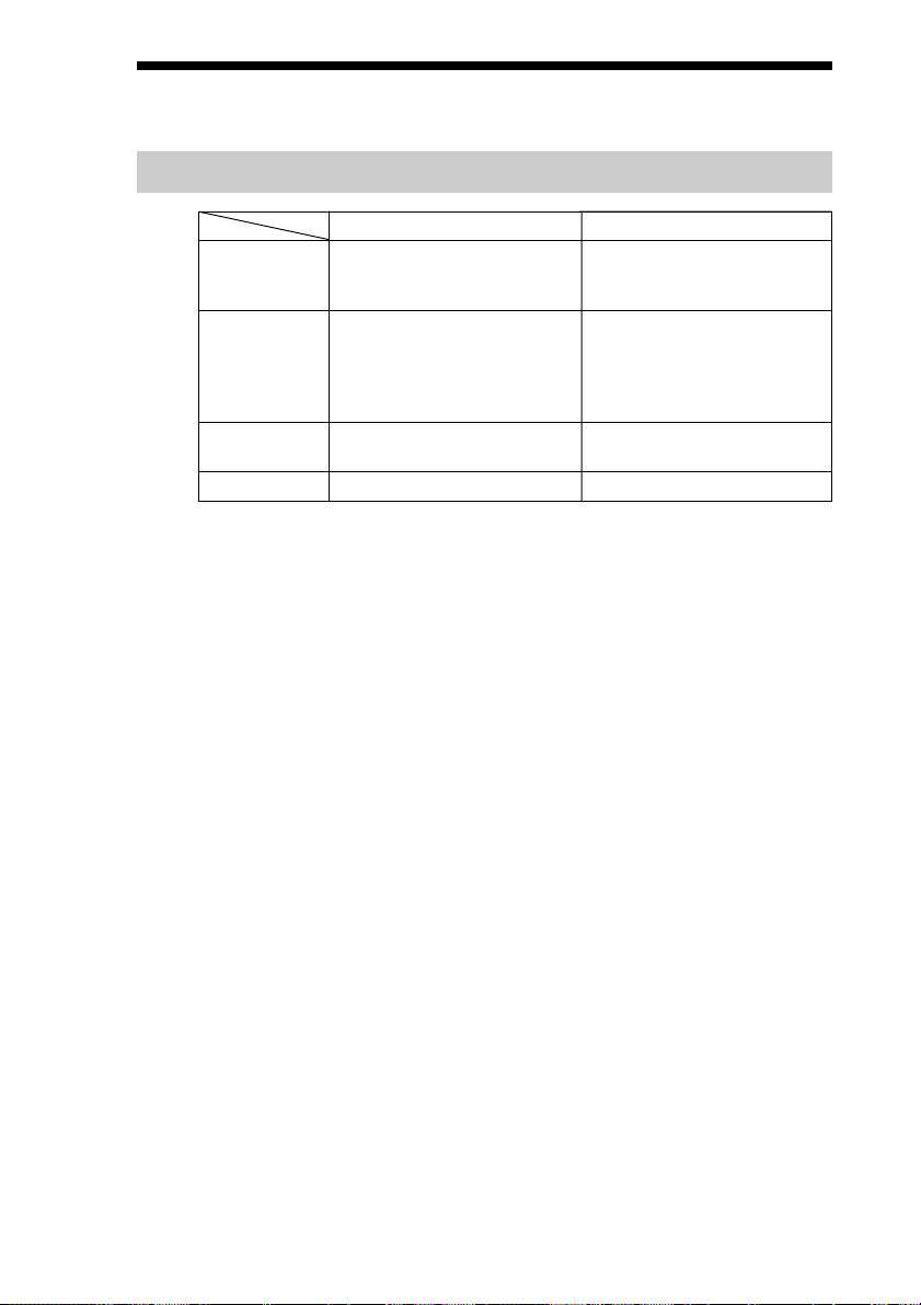
Product Features
SDX-570V
Data Capacity
Transfer Rate
(sustained)
Supported
Format
Buffer Memory
* Assuming a 2.6 : 1 compression ratio.
(The compression ratio varies according to the type of data.)
80 GB uncompressed
208 GB compressed*
(with TAIT2-80N or TAIT2-80C)
12 MB/s uncompressed
(with AIT-E Turbo, AIT-1 Turbo,
AIT-2, and AIT-2 Turbo)
8 MB/s uncompressed
(with AIT-1)
AIT-E Turbo, AIT-1, AIT-1
Turbo, AIT-2, AIT-2 Turbo
24 MB
SDX-470V
40 GB uncompressed
104 GB compressed*
(with TAIT1-40N or TAIT1-40C)
6 MB/s uncompressed
(with AIT-E Turbo and AIT-1
Turbo)
4 MB/s uncompressed
(with AIT-1)
AIT-E Turbo, AIT-1, AIT-1
Turbo
12 MB
• Burst Transfer Rate: 150 MB/sec
• 3.5" Standard Height, 5.25" Half Height
• SATA 1.5 Gbps (Gen.1)
• Frame Rewrite Function
• Three levels of Error Correction Code (ECC)
• High Speed search (120 times normal Read/Write speed)
• Random Read, Append Write
7

Precautions
Installation
Avoid placing the drive in a location subject to:
– high humidity
– high temperature
– mechanical shock and vibration
– direct sunlight
Operation
• Do not move the drive while it is operating. It may cause malfunction.
• Avoid exposing the drive to sudden changes from low to high
temperatures. This may cause water condensation to collect inside the
drive. If the ambient temperature should suddenly rise while the drive is
turned on , wait at least one hour before turning on the drive. If you
attempt to operate the drive immediately after a sudden increase in
temperature, a malfunction may occur.
• Turning off the power to the drive while it is writing to tape may cause
the tape to become unreadable. All previously negotiated parameters will
be lost, whenever power to the drive is cycled.
Transportation
• Keep the original packing materials to facilitate transportation of the
drive.
• Always remove the data cartridge before moving the drive. After
removing the drive from the computer, repack the drive into its original
packing.
8
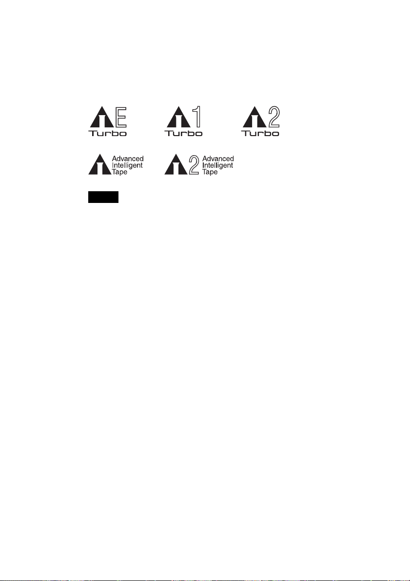
Useable Cartridges
The SDX-570V can be used with data cartridges marked with the AIT-E
Turbo, AIT-1 Turbo, AIT-2 Turbo, AIT-1 or AIT-2 logo.
The SDX-470V can be used with data cartridges marked with the AIT-E
Turbo, AIT-1 Turbo or AIT-1 logo.
Notes
• Be sure to use only the cartridges designed specifically for AIT.
• Do not use anything but AIT cartridges with this system, as doing so can
damage the AIT drive. Although commercially available 8 mm
videotapes resemble AIT cartridges in appearance, they have entirely
different specifications and cannot be used.
9
Installation
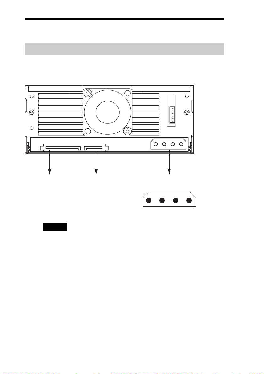
Connectors
The following figures apply to the SDX-570V.
SATA Power
Connector (*1)
Caution
DO NOT USE both the SATA Power Connector (*1) and Legacy Power
Connector (*2) at the same time.
Using both connectors possible cause the system damage.
SATA Signal
Connector
Legacy Power
Connector (*2)
4 3 2 1
5V GND GND 12V
10
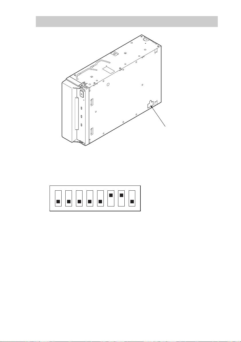
Option Switches (DIP Switch)
DIP Switch Positions
Default
ON
OFF
12345678
DIP Switch
1 Drive Mode (OFF)
2 Drive Mode (OFF)
3 Drive Mode (OFF)
4 Drive Mode (OFF)
5 Reserved (OFF)
6 Periodic Cleaning Req (ON)
7 DC Control (1) (ON)
8 DC Control (2) (OFF)
11

Cleaning Request Mode
Periodic cleaning requests can be enabled by a DIP switch.
1 Drive Mode
ON
OFF
12345678
2 Drive Mode
3 Drive Mode
4 Drive Mode
5 Reserved
6 Periodic Cleaning Req (ON)
7 DC Control (1)
8 DC Control (2)
When switch 6 is ON, cleaning requests are enabled. When enabled, the
“CLEANING REQUEST” LED on the front panel lights after every 100
hours of operation.
When this LED lights, clean the drive with a cleaning cartridge.
Note
To maintain the drive in optimum condition in environments affected by dust and other
contaminants, we recommend keeping cleaning requests enabled.
Data Compression Control DIP switch
Data compression can be selected by DIP switches. Data compression is
enabled while position 7 [DC Control (1)] is ON. Control by host can be
disabled when position 8 [DC Control (2)] is ON.
12
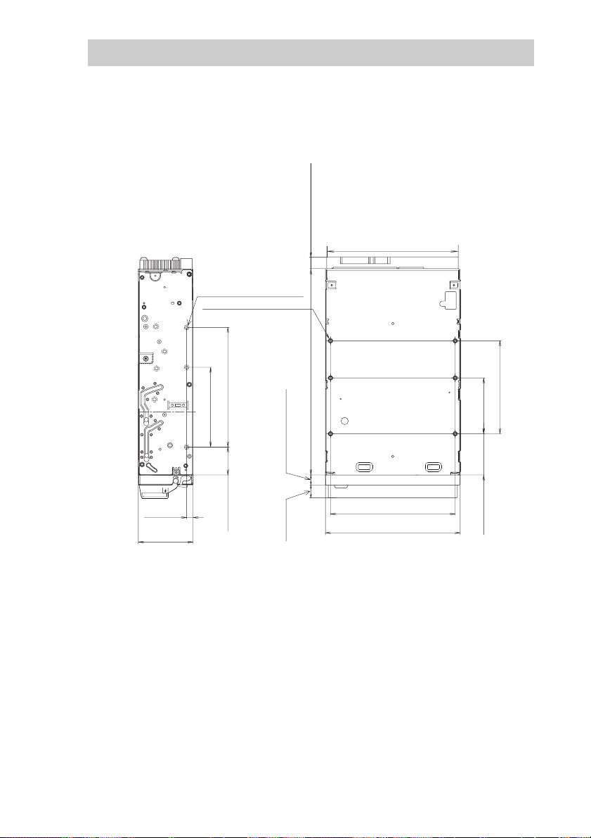
Mounting Holes
The following figures apply to the SDX-570V.
For 3.5" Standard Height
_
+
4.8 0.5mm
_
+
[0.19" 0.02"]
_
+
41.2 0.5mm
_
+
[1.62" 0.02"]
6-M3 (depth 2.5mm [0.10"] max.)
6-M3 (depth 2.5mm [0.10"] max.)
_
+
_
+
_
+
_
+
90.0 0.3mm [3.54" 0.01"]
60.0 0.3mm
[2.36" 0.01"]
_
+
_
+
21.0 0.3mm
[0.83" 0.01"]
_
+
_
+
7.4 0.6mm [0.29" 0.02"]
_
+
_
+
9.8 0.6 mm
[0.39" 0.02"]
8.3±0.5 mm (0.33±0.02 in)
_
+
_
+
155.0 0.5mm [6.10" 0.02"]
96.1 mm (3.78 in)
_
+
94.0 0.5mm [3.70" 0.02"]
_
+
101.6 0.5mm [4.00" 0.02"]
_
+
_
+
_
+
_
+
42.0 0.3mm
[1.65" 0.01"]
70.0 0.3mm [2.76" 0.01"]
_
+
_
+
_
+
_
+
31.0 0.3mm
[1.22" 0.01"]
13

For 5.25" Half Height
8.3±0.5 mm
(0.33±0.02 in)
146±0.5 mm
(5.75±0.02 in)
96.1 mm
(3.78 in)
7.0mm
[0.28"]
_
+
_
+
79.2 0.3mm [3.12" 0.01"]
_
+
9.9 0.5mm
_
[0.39" 0.02"]
+
_
+
21.8 0.5mm
_
+
[0.86" 0.02"]
_
+
41.2 0.5mm
_
+
[1.62" 0.02"]
6-M3
_
+
_
+
_
+
_
+
_
+
79.2 0.3mm [3.12" 0.01"]
_
+
_
+
47.5 0.3mm
[1.87" 0.01"]
_
+
_
+
_
+
155.0 0.5mm [6.10" 0.02"]
42.0 0.3mm
[1.65" 0.01"]
70.0 0.3mm [2.76" 0.01"]
_
+
_
+
_
+
_
+
9.8 0.6 mm
[0.39" 0.02"]
_
+
7.4 0.6mm [0.29" 0.02"]
_
+
31.0 0.3mm [1.22" 0.01"]
_
+
94.0 0.5mm [3.70" 0.02"]
_
+
139.6 0.5mm [5.50" 0.02"]
_
+
146.0 0.5mm [5.75" 0.02"]
_
+
149.0 0.5mm [5.87" 0.02"]
_
+
_
+
_
+
_
+
4-M3
_
+
_
+
79.2 0.3mm [3.12" 0.01"]
_
+
_
+
47.5 0.3mm
[1.87" 0.01"]
14
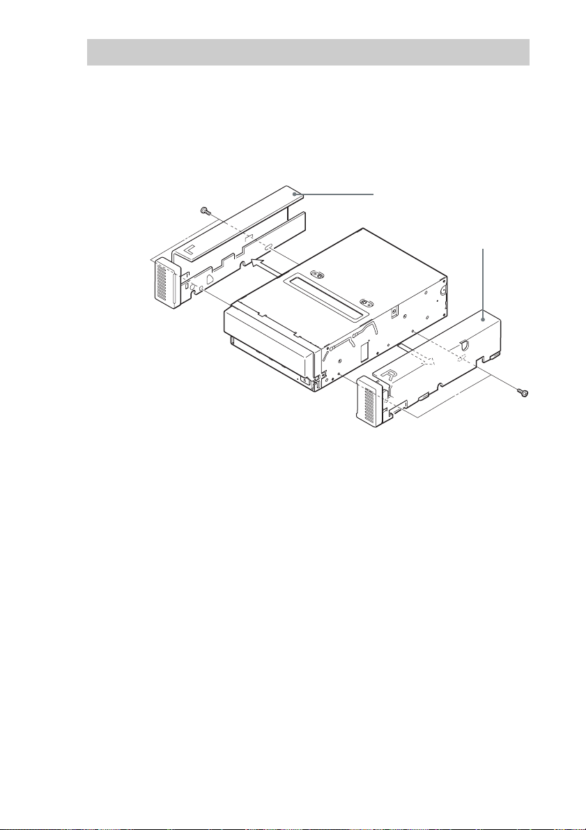
Reconfiguring from 5.25" Model to 3.5" Model
You can reconfigure the 5.25" model to the 3.5" model yourself.
1 Remove the 2 screws for each side rail.
2 Take the side rail off.
Side Rail (L)
Side Rail (R)
15
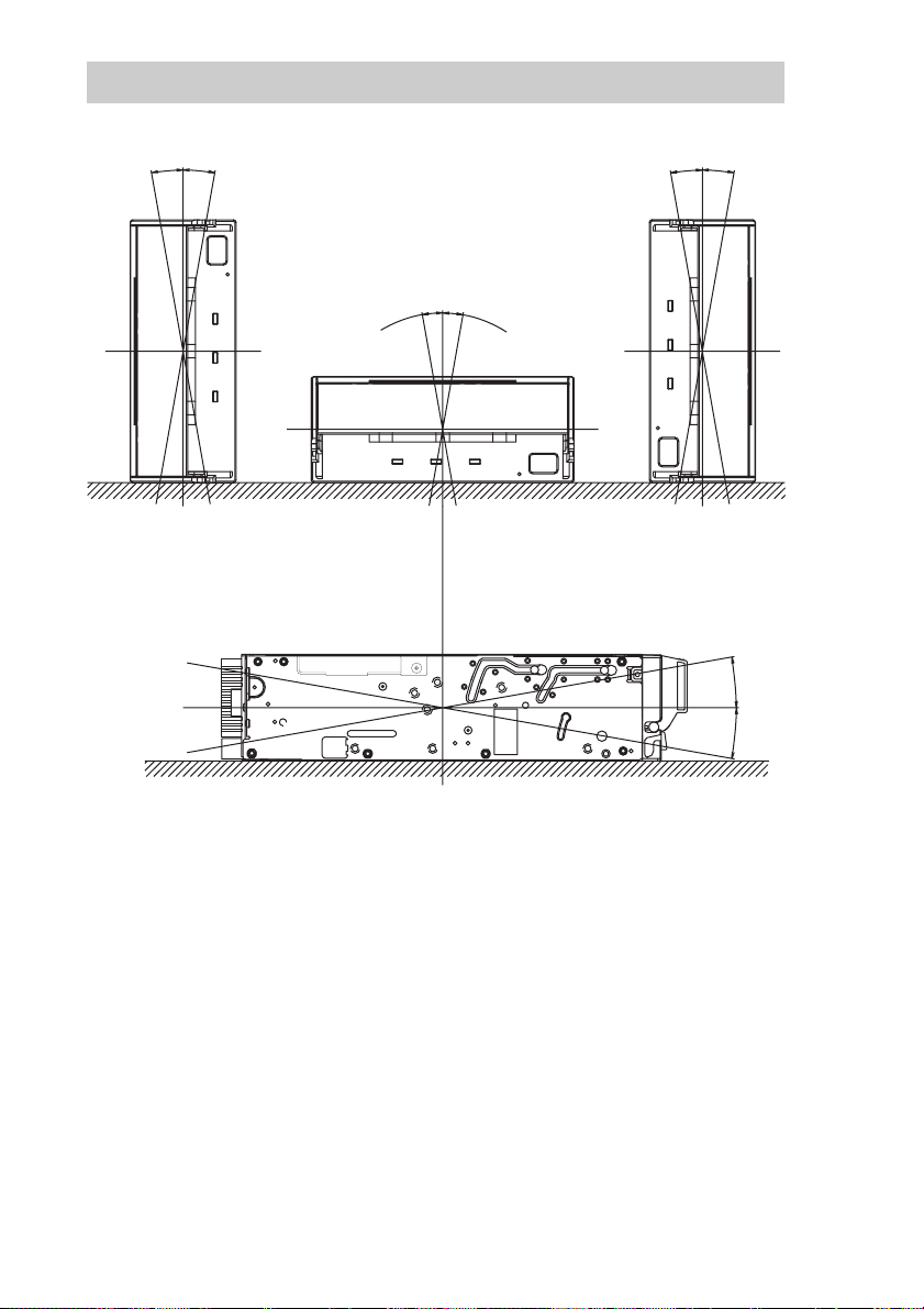
Orientation
10°10
10°10
°
10
°
10
°
°
10
°
10
°
16
Attaching and Removing the Dust
Cover
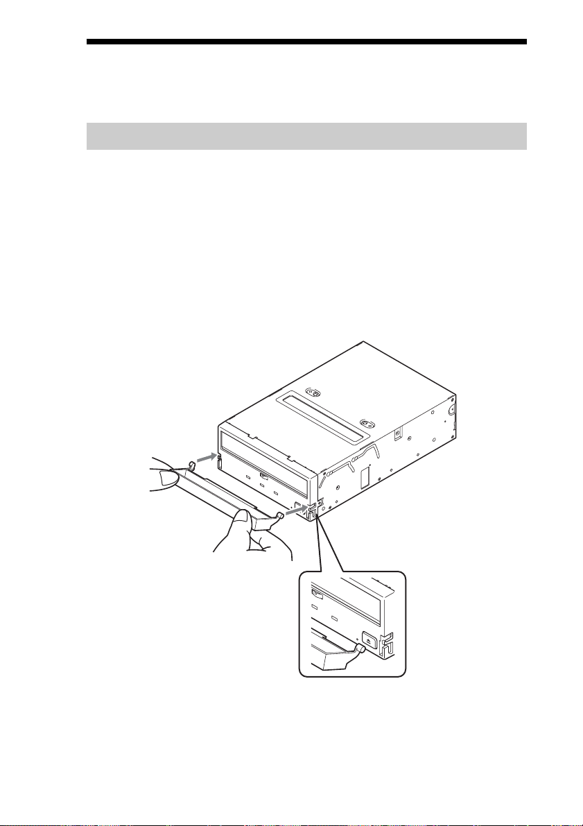
Attaching the Dust Cover
1 Align the dust cover’s hinge clips (one on each side) with the
pins of the drive bezel.
• The dust cover should be positioned so that the magnets* on the
cover’s back face the drive bezel.
*
This magnet does not affect the tape of the cartridge.
• Holding the dust cover at an angle as shown in the figure below, set
the hinge clips on top of the bezel pins, positioning them so that
they bracket the pins.
17
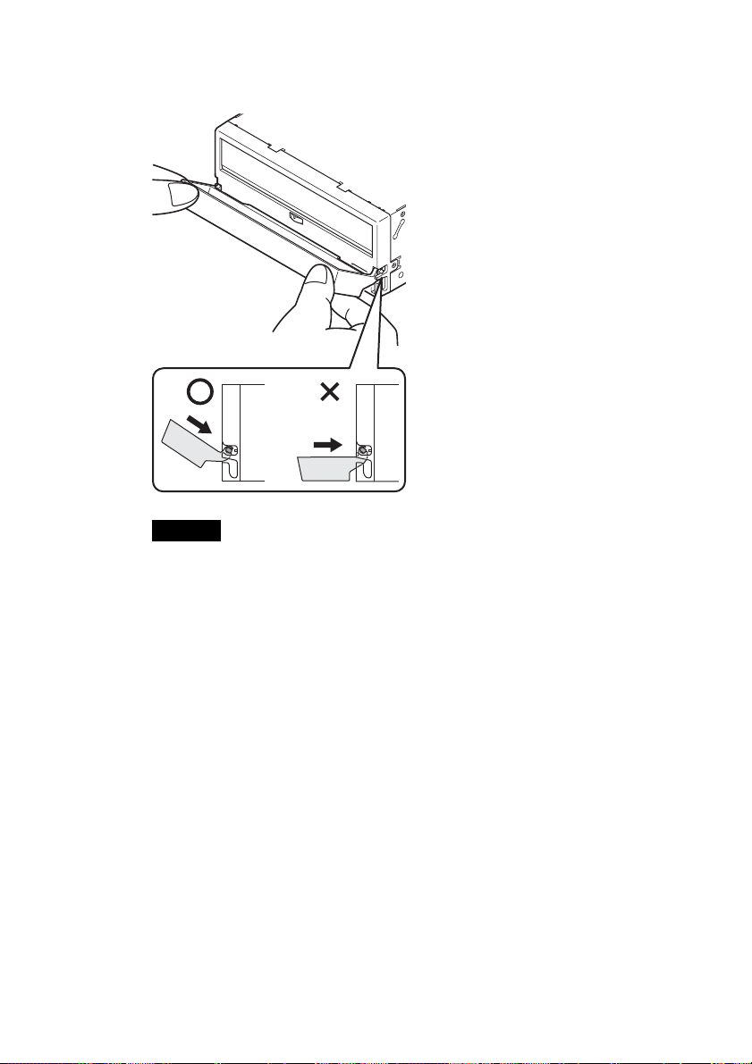
2 Press down at an angle on each side in turn until you hear
the hinge clips click into place.
Caution
Do not press the dust cover in horizontally from the front. Doing so
could cause the dust cover to break.
3 Close the dust cover.
This completes attachment of the dust cover.
18
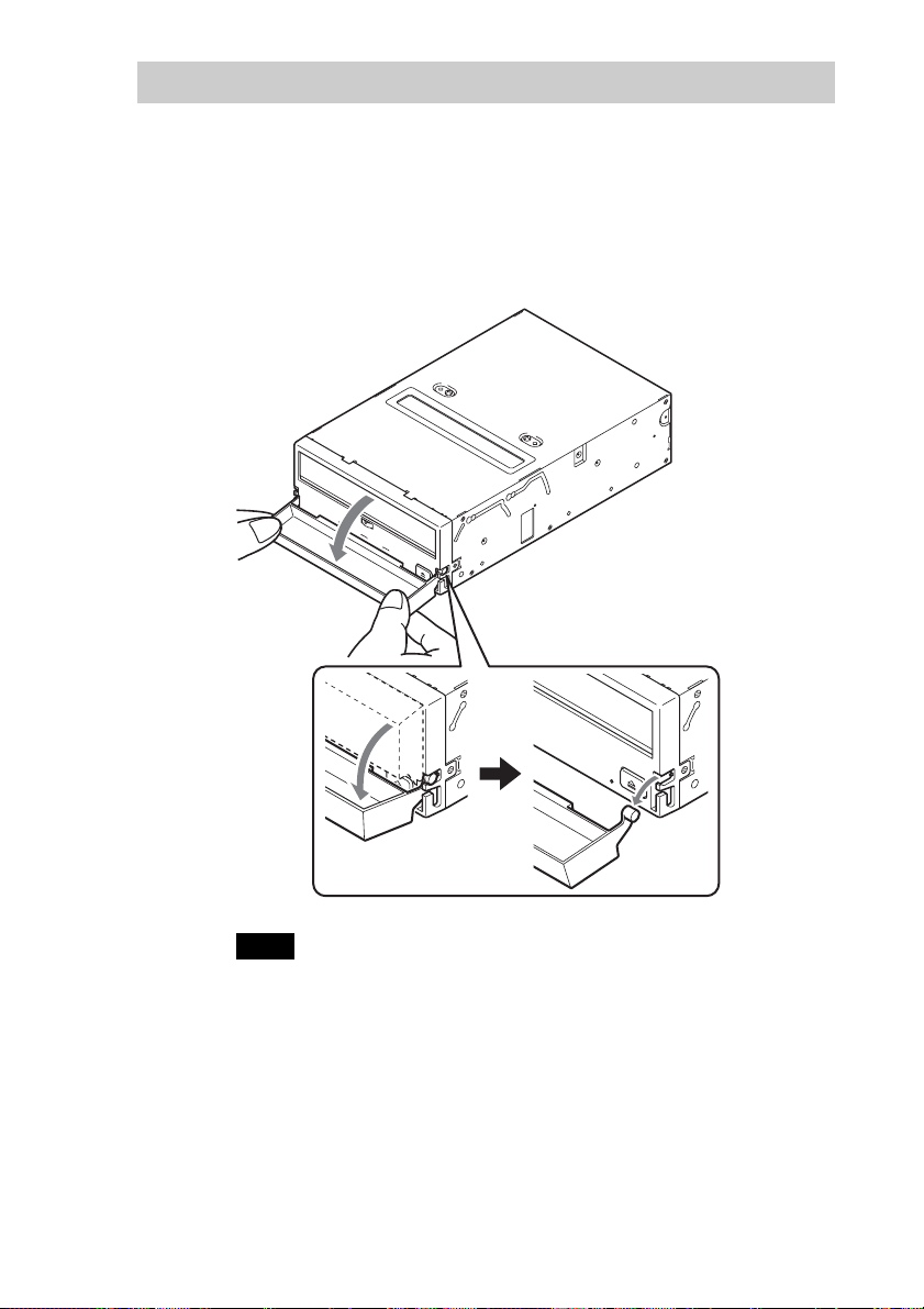
Removing the Dust Cover
1 Open the dust cover.
2 Holding the dust cover at both corners, carefully raise the
dust cover.
The dust cover hinge clips and drive bezel pins uncouple.
Note
We recommend that you use the drive with the dust cover.
19
Operation
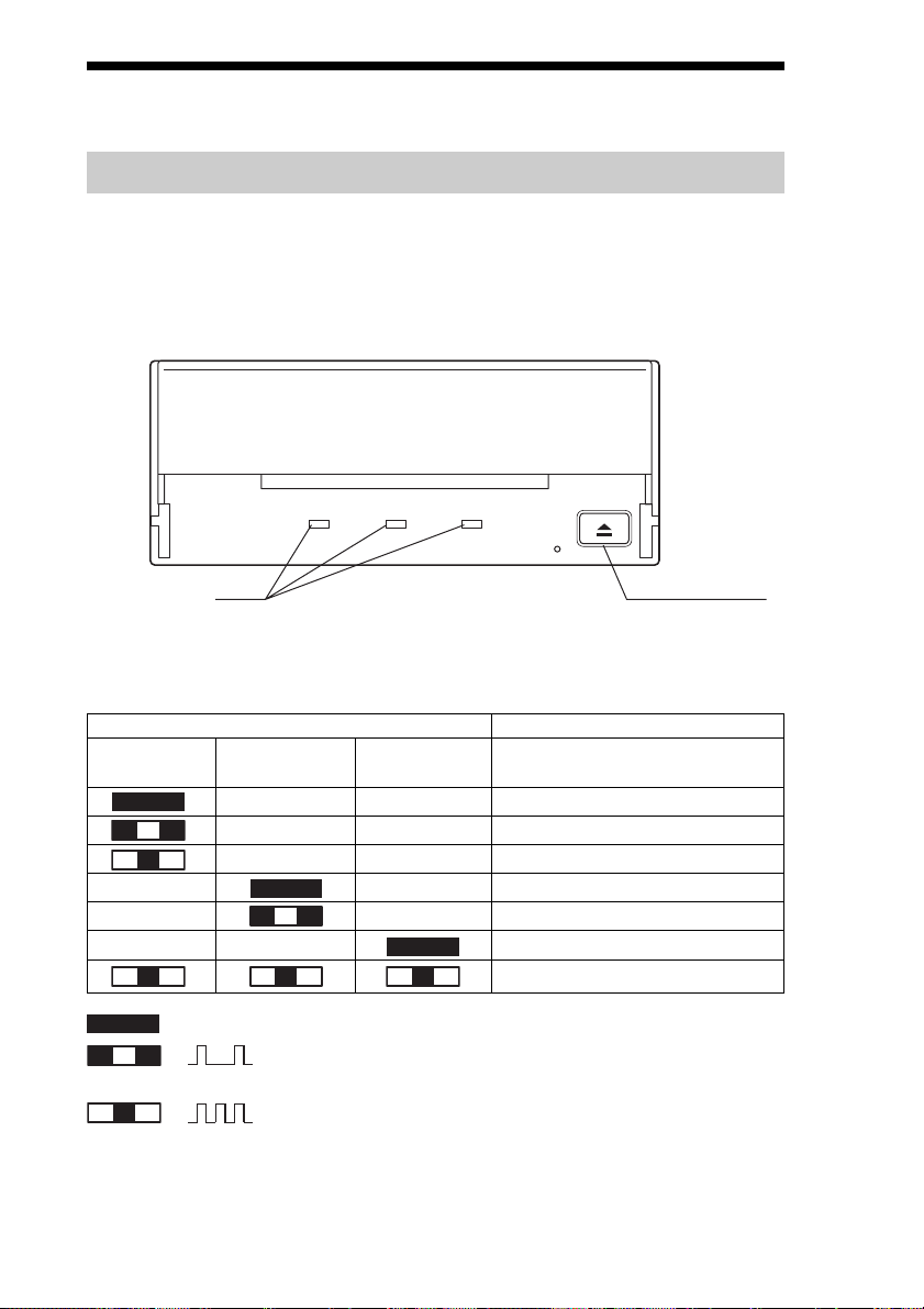
Location of 3 LEDs
There are three LED indications (TAPE MOTION LED, CLEANING
REQUEST LED, REPLACE TAPE LED) and an EJECT button on the
front panel of the unit.
Front Panel (for 3.5" Standard Height)
Advanced
Intelligent
Tape
TAPE
MOTION
CLEANING
REQUEST
REPLACE
TAPE
LED
EJECT button
LED Indication for Drive Status
The LED indicators are defined as follows.
LED
TAPE CLEANING REPLACE
MOTION REQUEST TAPE
Independent Independent Tape Loaded
Independent Independent Tape Access in Progress (write/read)
Independent Independent Tape Access in Progress (others)
Independent Independent Cleaning is requested
Independent Independent Cleaning is Not Completed
Independent Independent Media Error Occurred
H/W Error Occurred
on
Slow
1 pulse (0.9 sec on/0.3 sec off)
Fast
1 pulse (0.3 sec on/0.3 sec off)
Sense
20
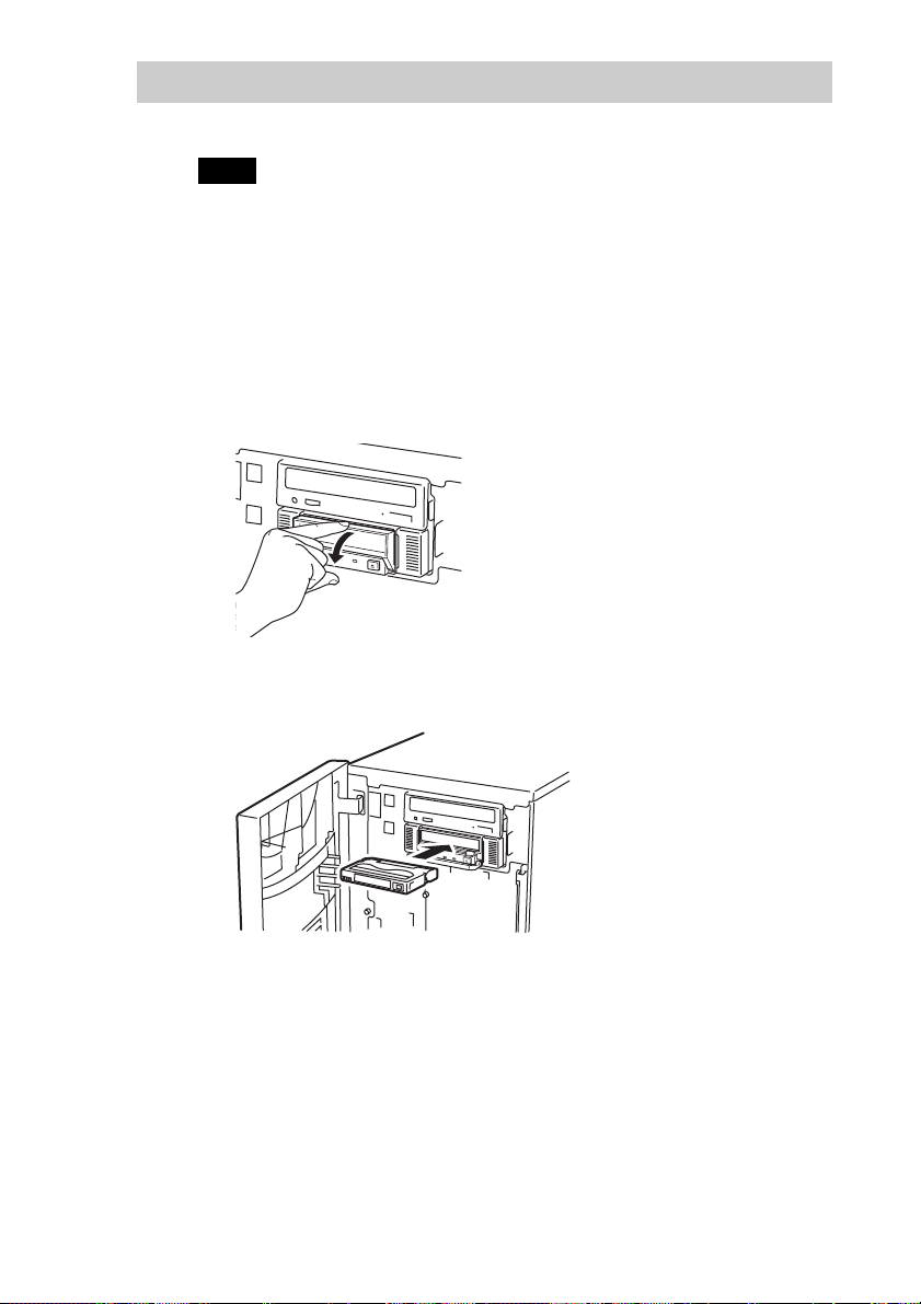
Drive Operation
Loading a Cartridge
Note
While setting the data cartridge, do not turn off the host computer. This
may cause a malfunction or damage data.
1 Turn on the host computer. Check that the drive’s TAPE
MOTION LED, CLEANING REQUEST LED and REPLACE
TAPE LED go off.
2 Open the dust cover.
3 Set the AIT data cartridge orientation as shown here and
insert it into the data cartridge slot.
By inserting the data cartridge to the extent, it is automatically set in
the drive and the TAPE MOTION LED lights.
Unloading a Cartridge
The cartridge can be removed from the SDX-570V and SDX-470V either in
response to a ATAPI Unload Command, or by pressing the EJECT bottom.
By pressing EJECT button, the tape is rewound and the cartridge ejected
from the slot.
21
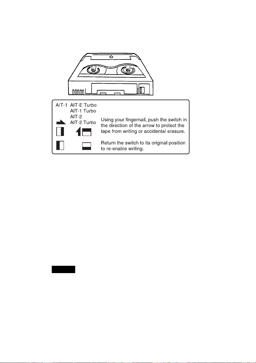
Write-protecting a Cartridge
Cartridges can be write-protected by sliding the tab on the back of the
cartridge. In this state, data can be read from the tape but not written onto it.
Using a Cleaning Cartridge
To keep the AIT drive in top condition, clean the head as needed using a
cleaning cartridge with the AIT logo. When the head needs cleaning, the
CLEANING REQUEST indicator lights.
How to Clean
1 Load the cleaning cartridge (SDX1-CL) into the AIT drive.
Cleaning starts automatically.
2 After about 15 seconds, cleaning will stop and the cartridge
will be ejected automatically.
Caution
Do not rewind the cleaning cartridge and reuse it. When you reach the end of
the cartridge, dispose it and buy a new cleaning cartridge with the AIT logo.
Storage Precautions
• Keep cartridges in their cases when not in the drives.
• Avoid storing cartridges in dusty locations, in direct sunlight, near heaters
or air conditioners, or in humid locations.
• Do not place cartridges on dashboards or in car storage trays.
22

Interface Implementation
Supported ATA Commands
– ATAPI SOFT RESET (0x08)
– EXECUTE DRIVE DIAGNOSTIC (0x90)
– ATAPI PACKET COMMAND (0xA0)
– ATAPI IDENTIFY DEVICE (0xA1)
– STANDBY IMMEDIATE (0xE0)
– IDLE IMMEDIATE (0xE1)
– CHECK POWER MODE (0xE5)
– SLEEP (0xE6)
– SET FEATURE (0xEF)
Supported ATAPI Packet Commands
Mandatory ATAPI command set:
Supporting most of all SCSI commands in the AIT Tape Drive.
– ERASE
– INQUIRY
– LOAD/UNLOAD
– LOCATE
– LOG SELECT
– LOG SENSE
– MODE SELECT
– MODE SENSE
– READ
– READ POSITION
– REQUEST SENSE
– REWIND
– SPACE
– TEST UNIT READY
– WRITE
– WRITE BUFFER
– WRITE FILEMARK
23
 Loading...