

Page 1
AIT Drive
User’s Guide
GB
CT
SDX-400C
Page 2

This document contains proprietary
information which is protected by
copyright.
All rights reserved. No part of this
document may be photocopied,
reproduced or translated to another
language without prior written consent
of Acer.
The information contained in this
document is subject to change without
notice.
Acer MAKES NO WARRANTY OF
ANY KIND WITH REGARD TO
THIS DOCUMENT.
Acer shall not be liable for error
contained herein, indirect, special,
incidental or consequential damages in
connection with the furnishing,
performance or use of this document.
VORSICHT
Diese Ausrüstung erfüllt die
Europäischen EMC-Bestimmungen für
die Verwendung in folgender /
folgenden Umgebung(en):
• Wohngegenden
• Gewerbegebiete
• Leichtindustriegebiete
(Diese Ausrüstung erfüllt die
Bestimmungen der Norm EN55022,
Klasse B.)
Contents
Introduction ....................................... 4
Product Features ........................4
Precautions ................................5
Installation ......................................... 7
SCSI Connection/Setting the
SCSI ID .................................7
Option Switches (DIP Switch) ..8
Mounting Holes........................9
Remodeling from 5.25" Model
to 3.5" Model .......................11
Orientation...............................12
Operation .........................................13
Location of 3 LEDs .................13
LED Indication for Drive
Status ...................................14
Drive Operation....................... 15
Emergency Tape Removal
Procedure .............................16
Interface Implementation................. 19
Supported SCSI Messages ...... 19
Supported SCSI Commands.... 19
Specification ....................................20
Product Specifications............. 20
Acer Contacts .................................. 22
2
Page 3

SDX-400C Tape Drive
The SDX-400C drive is a high capacity data storage device using
Advanced Intelligent tape AIT (Advanced Intelligent Tape) technology.
The SDX-400C drive achieves high data reliability through Read-AfterWrite, an additional level of Error Correction Code, and other features.
The SDX-400C drive stores data on tape using a standard format called
AIT and ALDC formats.
GB
3
Page 4

Introduction
Product Features
SDX-400C *
Data Capacity
Transfer Rate (sustained)
* Data compression function is available with SDX-400C.
• Supported Format : AIT-1 (Not support AIT-2 format)
• Burst Transfer Rate
– 12 MBytes/sec Asynchronous
– 40 MByte/sec Synchronous
• Large 10 M Byte Buffer Memory
• 3.5” form factor, 5.25” from factor
• Embedded SCSI Interface
(ULTRA/WIDE and LVD/SE (single-ended) model (SDX-400C))
• Supports Variable or Fixed Record Length
• Supports SCSI Disconnection/Arbitration
• Frame Rewrite Function
• Three levels of Error Correction Code (ECC)
• High Speed search (120 times normal Read/Write speed)
• Random Read, Append Write
35 GByte capacity (with AIT-1 230 m tape)
(approximately 70 GByte to 105 GByte with Data
Compression)
4 MByte/sec
(approximately 8 MByte/sec to 12 MByte/sec with
Data Compression)
4
Page 5

Precautions
Installation
Avoid placing the drive in a location subject to:
– high humidity
– high temperature
– mechanical shock and vibration
– direct sunlight
Operation
• Do not move the drive while it is operating. It may cause malfunction.
• Avoid exposing the drive to sudden changes from a low to high in
temperature. This may cause water condensation to collect inside the
drive. If the ambient temperature should suddenly rise while the drive is
turned on , wait at least one hour before turning on the drive. If you
attempt to operate the drive immediately after a sudden increase in
temperature, a malfunction may occur.
• Turning off the power to the drive while it is writing to tape may cause
the tape to become unreadable. All previously negotiated parameters will
be lost, whenever power to the drive is cycled.
Transportation
• Keep the original packing materials to facilitate transportation of the
drive.
• Always remove the tape before moving the drive. After removing the
drive from the computer, repack the drive into its original packing.
5
Page 6
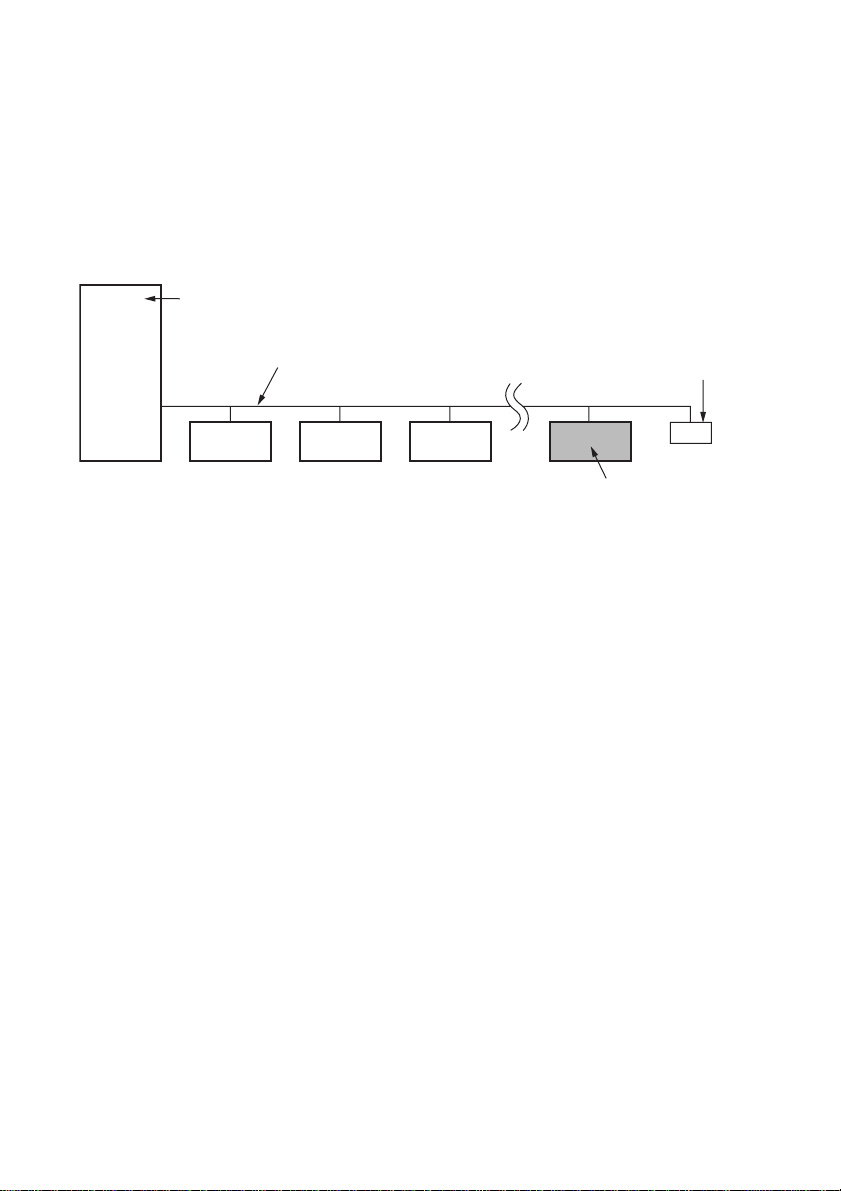
Notice of SCSI Termination
r
The SDX-400C conforms to the Microsoft PC97 standard which requires
the internal (naked) drive to be terminated with an external terminator.
Microsoft PC97 SCSI requirements
SCSI peripherals must not terminate the bus. Both internal and external
cable ends are instead terminated by plug-in connectors.
Host Computer Wide SCSI
68p cable
Exapmle of SCSI set-up
Terminato
This drive
6
Page 7
Installation
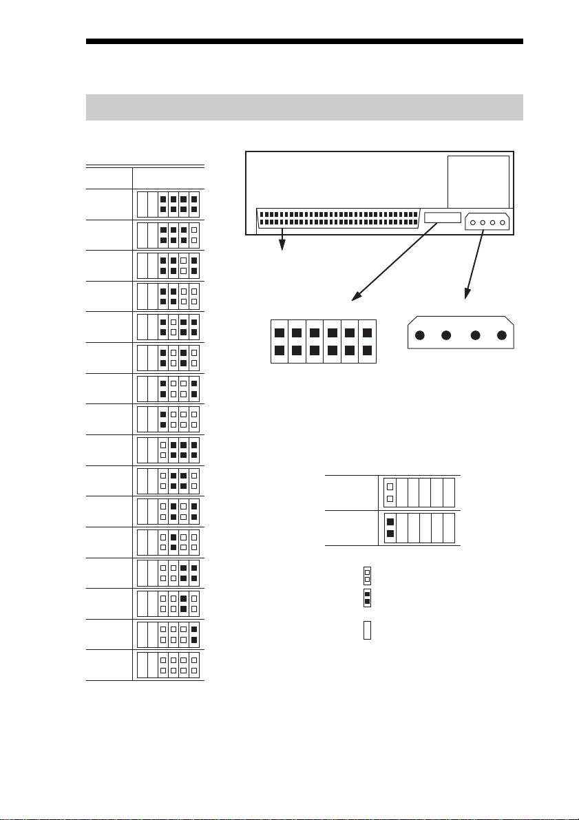
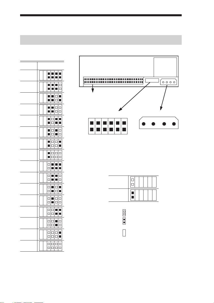
SCSI Connection/Setting the SCSI ID
SCSI ID
210
SCSI ID
0
1
P.D.
N.C.
3
10
11
12
13
14
2
3
4
5
SCSI 68pin Connector
Jumpers
Power Connector
5 V
GND GND 12 V
1234
6
SCSI ID 3
SCSI ID 2
SCSI ID 1
7
Parity Disable
8
No Connection
Parity
SCSI ID 0
9
Disable
Enable
Note := = CLOSED/Jumper
OPEN/Jumper not
installed
Don’t care
15
Parity Disable Jumper
Parity check function can be disabled by Jumper. Parity check is disabled
while left end jumper is installed. Parity generate function is always
enabled.
7
Page 8
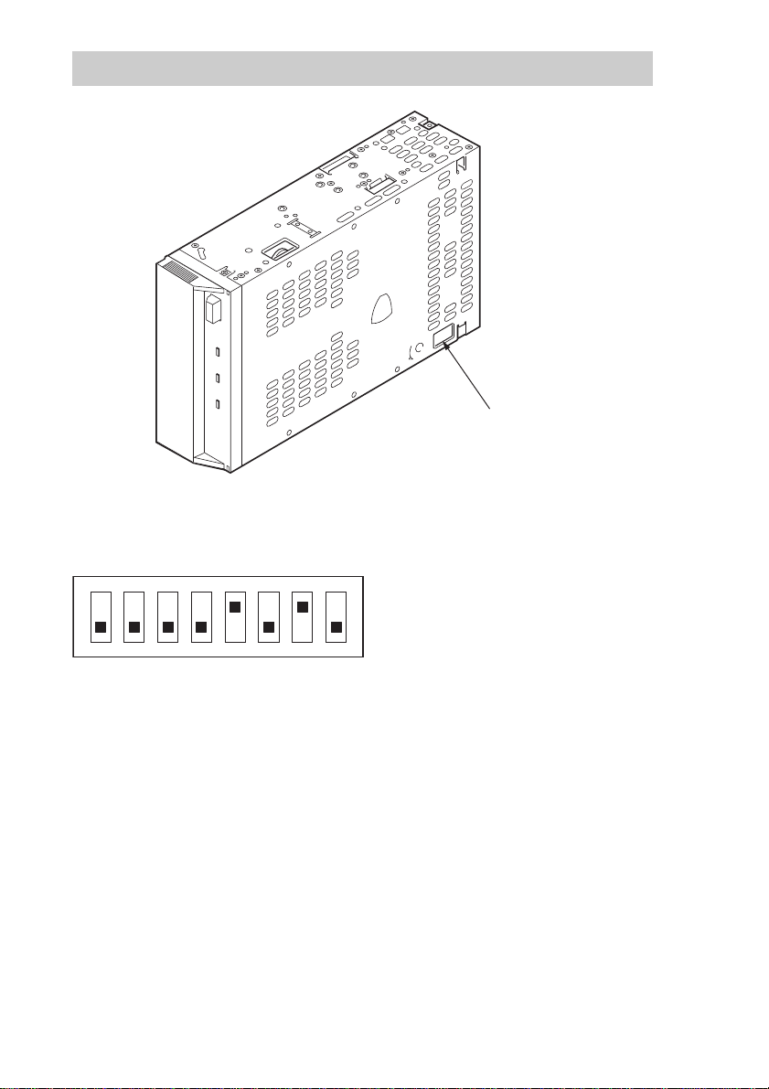
Option Switches (DIP Switch)
DIP Switch Positions
DIP Switch
ON
12345678
1 Reserved (OFF)
2 Reserved (OFF)
3 Reserved (OFF)
4 Reserved (OFF)
5 Terminator Power (ON)
6 Reserved (OFF)
7 DC Control (1) (ON)
8 DC Control (2) (OFF)
Data Compression Control DIP switch
Data compression can be selected by DIP switches. Data compression is
enabled while position 7 [DC Control (1)] is ON. Control by host can be
disabled when position 8 [DC Control (2)] is ON.
8
Page 9
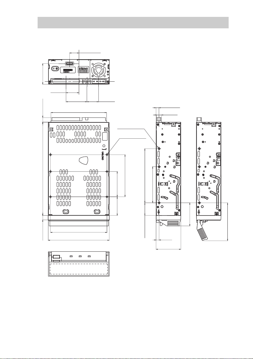
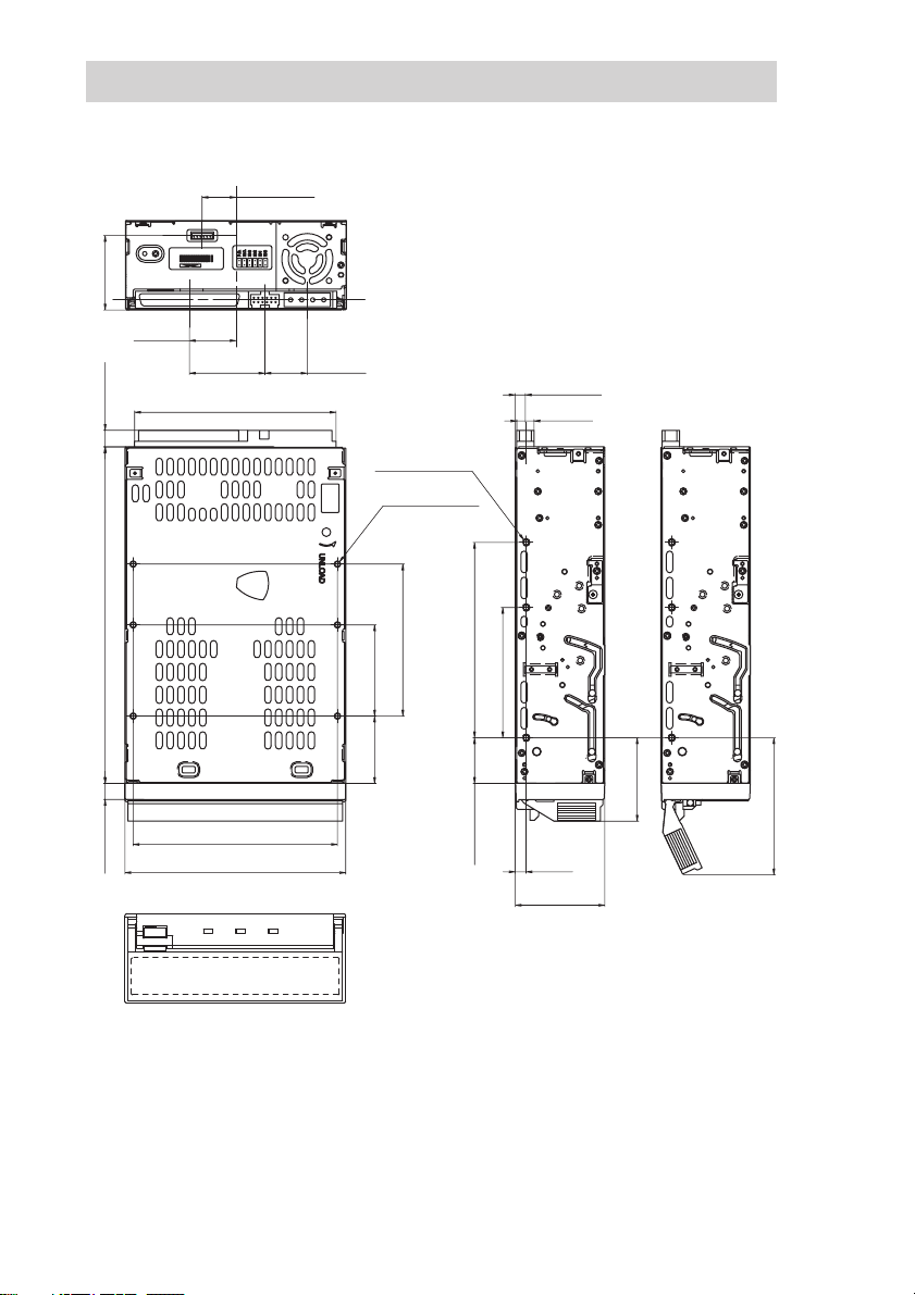
Mounting Holes
For 3.5" Standard Height (SDX-400C)
15.6 ±0.5 mm
[0.61"±0.02"]
SDX-400C
9911
[1.35"±0.02"]
34.3 ±0.5 mm
21.465 mm
[0.85"]
[0.3"±0.02"]
7.6 ±0.5 mm
[6.1" ±0.02"]
155 ±0.5 mm
34.75 mm
[1.37"]
92.71 mm
[3.65"]
19.48 mm
[0.77"]
6-M3 (depth 2.5mm [0.10"] max.)
6-M3 (depth 2.5mm [0.10"] max.)
70 ±0.3 mm
42 ±0.3 mm
[1.65" ±0.01"]
[2.76" ±0.01"]
90 ±0.3 mm
[3.54" ±0.01"]
60 ±0.3 mm
[2.36" ±0.01"]
4.7 ±0.5 mm
[0.19" ±0.02"]
8 mm
[0.31"]
7.4 ±0.5 mm
[0.29" ±0.02"]
94 ±0.3 mm
[3.7" ±0.01"]
101.6 ±0.5 mm
[4" ±0.02"]
31 ±0.3 mm
[1.22" ±0.01"]
21 ±0.3 mm
[0.83" ±0.01"]
5 ±0.3 mm
[0.2" ±0.01"]
41.2 ±0.5 mm
[1.62" ±0.02"]
[1.51"]
38.4 mm
[2.51"]
63.8 mm
9
Page 10
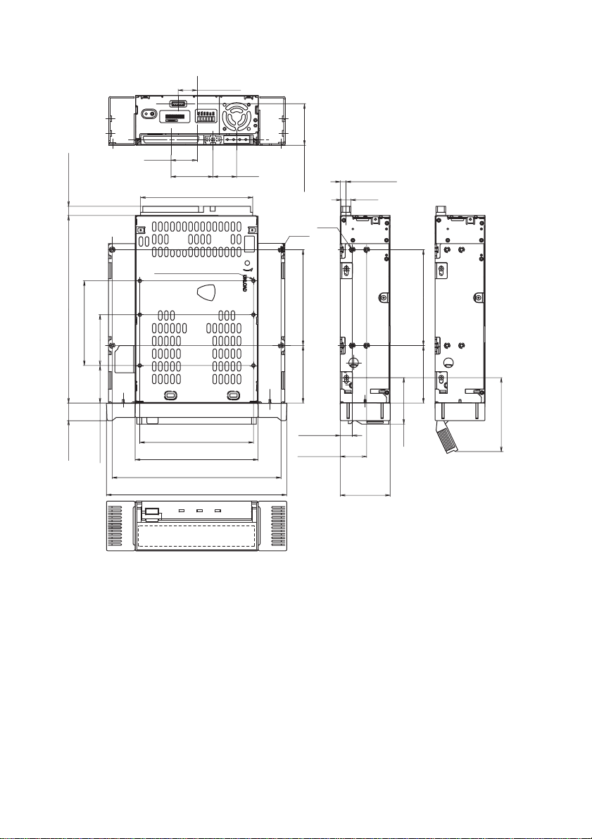
For 5.25" Half Height (SDX-400C/R)
15.6 ±0.5 mm
[0.61" ±0.02"]
SDX-400C/R
0101
21.465 mm
7.6 ±0.5 mm
[0.3" ±0.02"]
[6.1" ±0.02"]
155.0 ±0.5 mm
70.0 ±0.3 mm
[2.76" ±0.01"]
42.0 ±0.3 mm
[1.65" ±0.01"]
[0.85"]
34.75 mm
[1.37"]
92.71 mm
[3.65"]
6-M3(depth 2.5mm (0.10") max.)
19.48 mm
[0.77"]
34.3 ±0.5 mm
4-M3
0.3 mm
±
79.2
[1.35" ±0.02"]
[3.12" ±0.01"]
4-3M
4.7 ±0.5 mm
[0.19" ±0.02"]
8 mm
[0.31"]
P
P
P
P
P
79.2 ±0.3 mm
[3.12" ±0.01"]
P
P
P
[0.56" ±0.01"]
14.4 ±0.3 mm
31.0 ±0.3 mm
[1.22" ±0.01"]
94.0 ±0.3 mm
[3.7" ±0.01"]
101.6 ±0.5 mm
[4" ±0.02"]
139.6 ±0.5 mm
[5.5" ±0.02"]
149.0 ±0.5 mm
[5.87" ±0.02"]
47.5 ±0.3 mm
[1.87" ±0.01"]
9.9 ±0.5 mm
[0.39" ±0.02"]
21.8 ±0.5 mm
[0.86" ±0.02"]
41.2 ±0.5 mm
[1.62" ±0.02"]
[1.51"]
38.4 mm
47.5 ±0.3 mm
[1.87" ±0.01"]
±0.3 mm
[2.45" ±0.01"]
62.4
10
Page 11
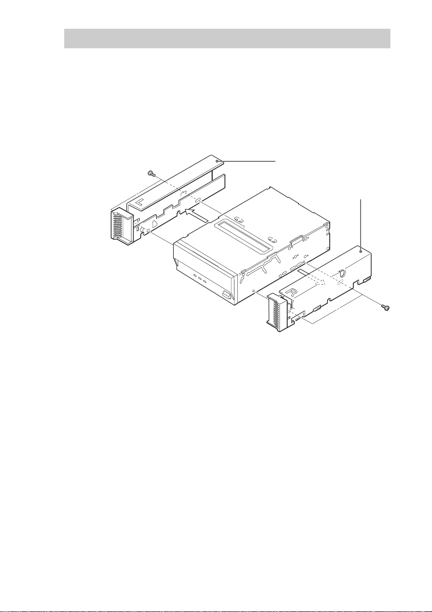
Remodeling from 5.25" Model to 3.5" Model
You can remodel the SDX-400C/R (5.25" model) to the SDX-400C (3.5"
model) yourself.
1 Remove the 2 screws for each side rail.
2 Take the side rail off.
Side Rail (L)
Side Rail (R)
11
Page 12
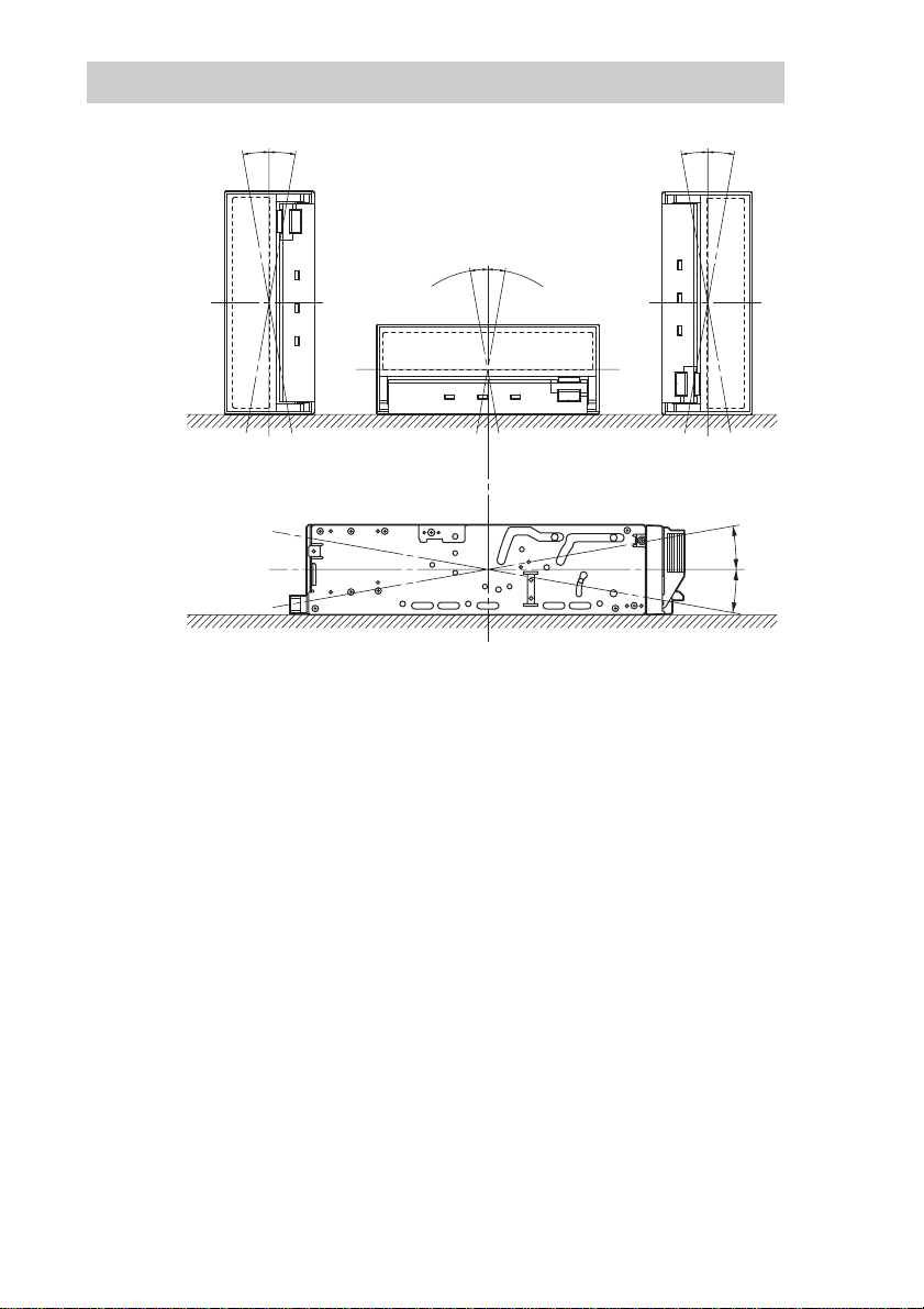
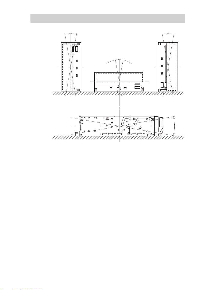
Orientation
10°
10° 10° 10°
10°
10°
10°
10°
12
Page 13
Operation
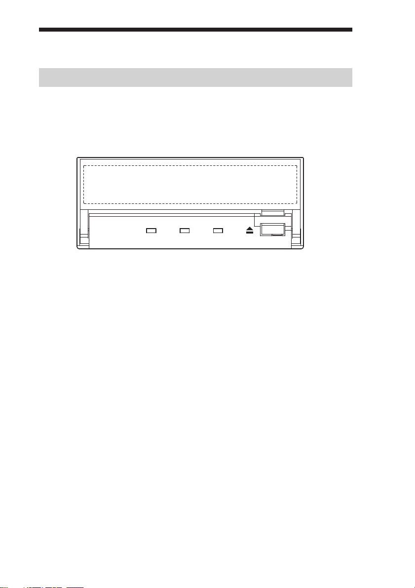
Location of 3 LEDs
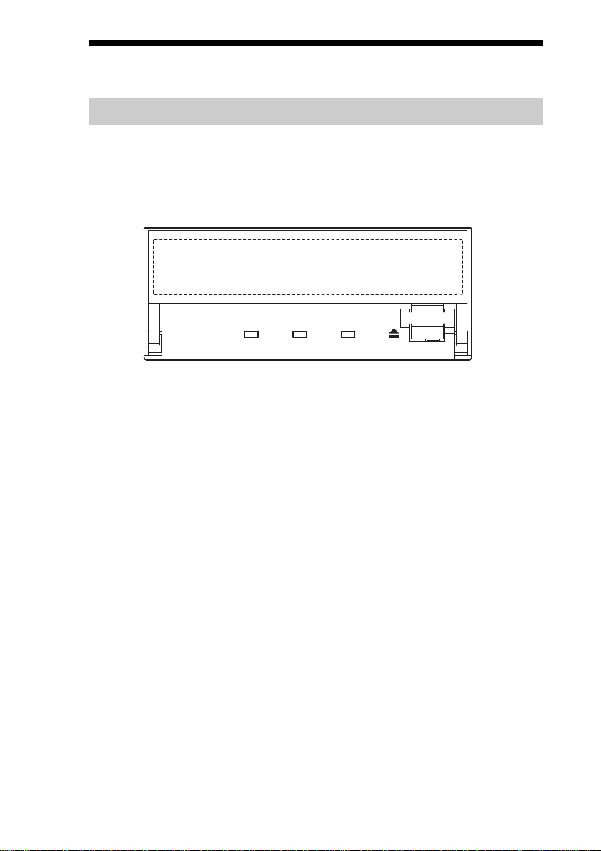
There are three LED indications (BUSY,TAPE and STATUS) and an
EJECT button on the front panel of the unit.
Front Panel (for 3.5" Standard Height)
Advanced
Intelligent
Tape
BUSY TAPE STATUS
BUSY TAPE S TATU S
13
Page 14
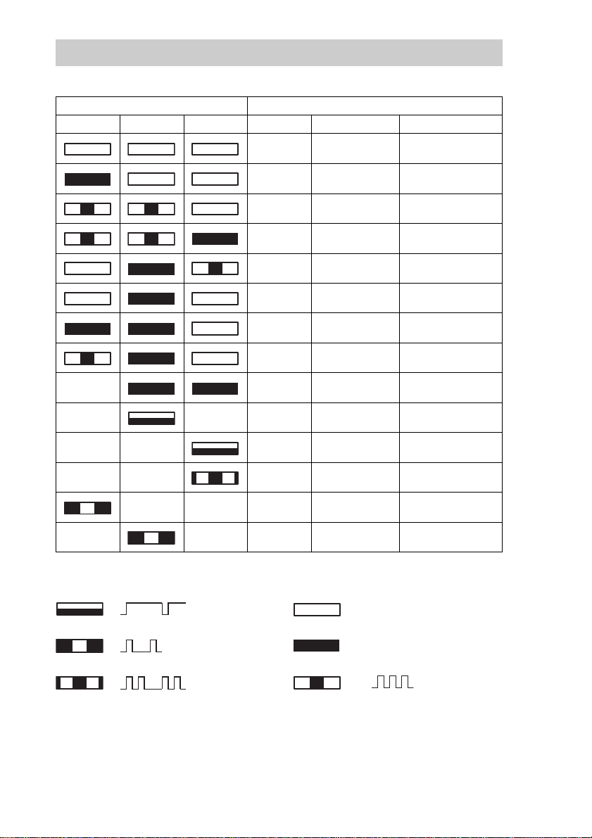
LED Indication for Drive Status
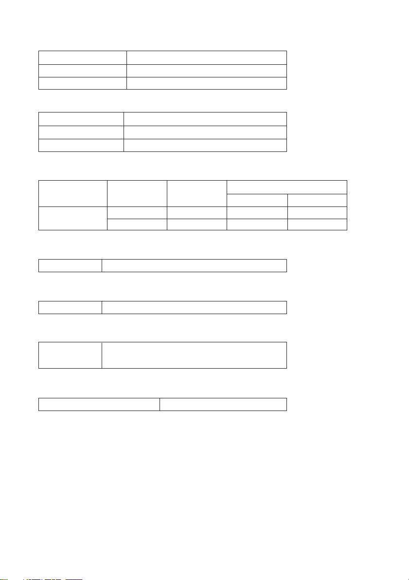
The LED indicators are defined as follows.
LED State
BUSY TAPE STATUS Activity Cartridge Other
None None None
SCSI None None
Drive
Drive
None Loaded
None Loaded None
SCSI Loaded None
SCSI/Drive Loaded None
Independent ✽ Loaded Write Protected
Independent Independent ✽ Loaded Error Rate Warning
✽✽ ✽✽Cleaning Request
✽✽ ✽✽Self test Failure
✽✽✽ ✽Waiting for Reset
✽ ✽✽ ✽Waiting for Eject
1 pulse (3.5 sec on / 0.5 sec off)
1 pulse (0.25 sec on)
Loading/Unloading
Loading/Unloading
off
on
None
Write Protected
Cleaning Tape at EOM
✽ : Not defined.
14
2 pulses (0.25 sec on/0.5 sec off)
1 pulse (0.25 sec on / 0.25 sec off)
Page 15

Drive Operation
Loading a Tape
Insert a cassette into the slot on the front panel with the arrow on the
cassette pointing towards the drive. As the cassette is inserted, the drive
takes it and automatically loads it into drive mechanism.
Unloading a Tape
The cassette can be removed from the SDX-400C either in response to a
SCSI Unload Command, or by pressing the eject bottom.
By pressing Eject button, the tape goes to BOT, the drive unthreads it, and
ejects the cassette from the slot.
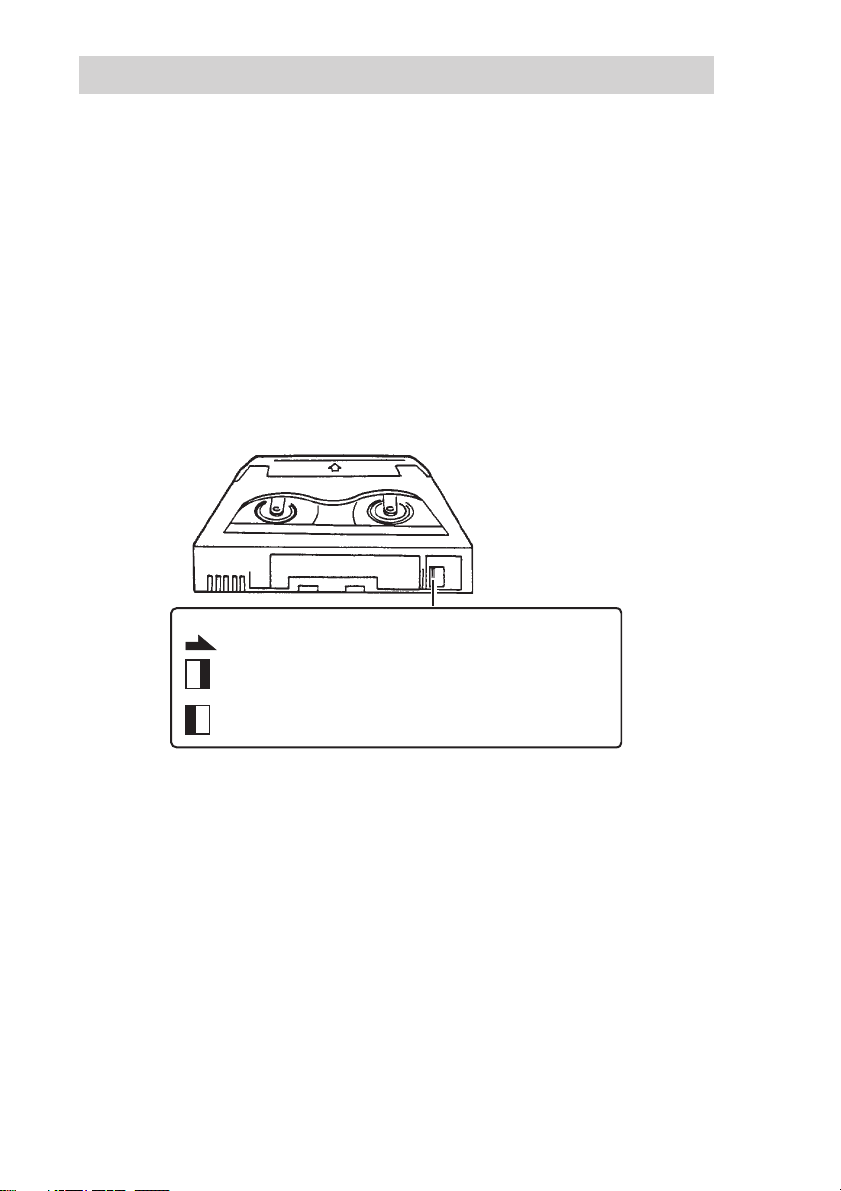
Write-protecting a Tape
Cassettes can be write-protected by sliding the tab on the back of the
cassette. In this state, data can be read from the tape but not written onto it.
AIT-1
Using your fingernail, push the switch in the
direction of the arrow to protect the tape from
writing or accidental erasure.
Return the switch to its original position to
re-enable writing.
Using a Cleaning Cassette
In case of SDX-400, a cleaning function is built in the drive and hence, a
periodic cleaning using cleaning cassette such as other format requires is
not necessary. However, when the drive does not recover at the worst case,
cleaning cassette is recommended to use.
15
Page 16

Emergency Tape Removal Procedure
1 Remove the drive from the chassis or enclosure to allow
access to the bottom and right side of the drive.
2 Remove the drive’s top cover.
3 Locate the small opening in the bottom of the drive and
insert the tip of a precision screwdriver so that the Threading
motor shaft can be rotated.
4 Rotate the motor shaft counterclockwise to bring the
threading mechanism back to the initial position. (Refer to
the photo-1 on page 18.)
5 Before manual eject procedure, tape slack must be removed
in order to prevent tape damage. Press and rotate the gear
mechanism located on the right side of the drive clockwise to
tighten the tape.
6 After the tape slack has been removed, turn the screw
located on the right side of the drive clockwise by a precision
screwdriver until the tape cartridge is lifted out of the drive
mechanism and is ejected.
16
Page 17

7 Return the drive to Acer for repair.
3. Cassette Compartment Motor
2. Reel Motor
1. Loading Motor
17
Page 18

A
tape guide surface
tape guide surface
C
B
Photo-1: The Initial Position of the Threading Mechanism
Caution
Stop rotating the motor shaft immediately, when the guide B (see detail A of Photo-1)
gets to the area below the line C-C (This line is defined by 2 circular tape guide surfaces
of the cartridge). Otherwise the gear of the drive can be damaged.
detail A
Cartridge
C
18
Page 19

Interface Implementation
Supported SCSI Messages
Abort Message Parity Error
Bus Device Reset Message Reject
Command Complete No Operation
Disconnect Restore Pointers
Extended Message Save Data Pointer
– Synchronous Data Transfer
Request
– Wide Data Transfer Request
Identify ( w/&w/o Disconnect )
Ignore Wide Residue
Supported SCSI Commands
Erase Receive Density Support
Inquiry Report Luns
Load/Unload Request Block Address
Locate Request Sense
Log Sense Reserve Unit
Log Select Rewind
Mode Select Seek Block
Mode Sense Send Diagnostic
Prevent Allow Medium Removal Space
Read Test Unit Ready
Read Block Limits Verify
Read Buffer Write
Read Position Write Buffer
Report Diagnostic Result Write Filemarks
Release Unit
19
Page 20
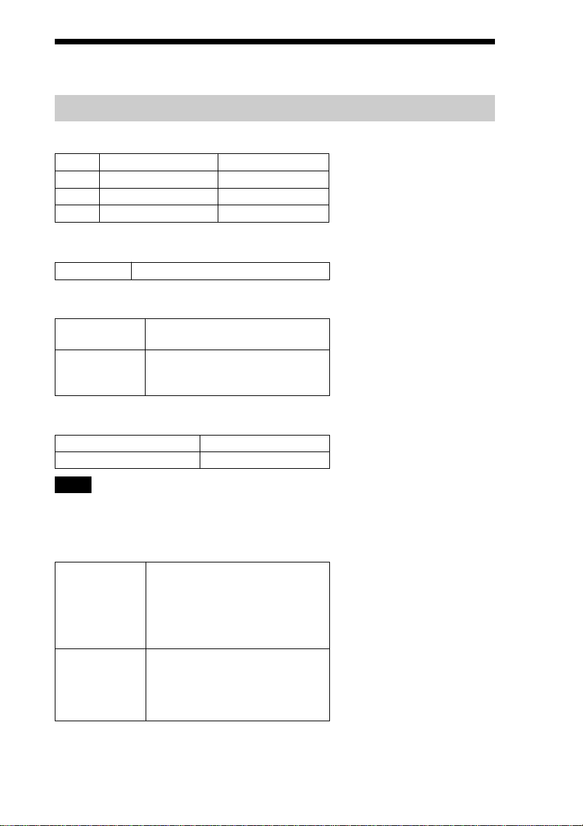
Specification
Product Specifications
Dimensions
SDX-400C SDX-400C/R
Height 41.2 mm (1.62 in) 41.2 mm (1.62 in)
Width 101.6 mm (4.0 in) 149.0 mm (5.87 in)
Depth 155.0 mm (6.1 in) 155.0 mm (6.1 in)
Altitude
Operating 0 to 10,000 feet
Vibration
Operating Swept Sine 5 to 500 Hz
Non-Operating Swept Sine 5 to 500 Hz
Acoustic Noise (A) curve weight
Streaming Write/Read 35 db (A)
Insert/Eject 60 db (A)
*0.25 G Peak 1 Octave/min.
*0.5 G Peak 1 Octave/min.
3 axes, 3 directions
Note
The sound-meter on (A) scale is located 1m in front of
the center of the drive front panel.
Shock
Operating No Data Loss
Non-Operating No Device Damage
Half Sine
Performance
5 G Peak 3 ms
3 axes, 3 directions
*Interval 10 seconds
Half Sine
90 G Peak 3 ms
(30 G Peak 11 ms)
3 axes, 3 directions
20
Page 21

Temperature and Humidity Range
Temperature
Operating 5 ˚C to 40 ˚C (∆T<10 ˚C/h)
Non-Operating (mech.) – 40 ˚C to 70 ˚C (∆T<20 ˚C/h)
Non-Operating (tape) – 40 ˚C to 45 ˚C (∆T<20 ˚C/h)
Humidity
Operating 20 to 80% RH, non-condensing
Maximum wet bulb temperature = 26 ˚C
Non-Operating (mech.) 5 to 95% RH (∆T<30%/h)
Non-Operating (tape) 20 to 80% RH (∆T<30%/h)
Power Requirements
Model Voltage Max Ripple
SDX-400 series
5 V +/– 5 % 100 mVp-p 1.3 A 2.5 A
12 V +/– 10 % 150 mVp-p 0.4 A 1.2 A
Suspended Particulate
Operating
Less than 150 microgram/m
Based Sampling period 24 hours
3
ESD
Discharge < 15 kV: No operation failure
Voltage < 20 kV: No drive damage
Current
Typical Maximum
Air-cooling Requirement
Surrounding temperature < 40 ˚C
Clean air flow is recommended to minimize the possibility of data loss.
21
Page 22

Acer Contacts
For further information, please contact:
http://csd.acer.com.tw/
22
Page 23

This document contains proprietary
information which is protected by
copyright.
All rights reserved. No part of this
document may be photocopied,
reproduced or translated to another
language without prior written
consent of Acer.
The information contained in this
document is subject to change
without notice.
Acer MAKES NO WARRANTY OF
ANY KIND WITH REGARD TO
THIS DOCUMENT.
Acer shall not be liable for error
contained herein, indirect, special,
incidental or consequential damages
in connection with the furnishing,
performance or use of this document.
VORSICHT
Diese Ausrüstung erfüllt die
Europäischen EMC-Bestimmungen
für die Verwendung in folgender /
folgenden Umgebung(en):
•Wohngegenden
• Gewerbegebiete
• Leichtindustriegebiete
(Diese Ausrüstung erfüllt die
Bestimmungen der Norm EN55022,
Klasse B.)
目錄
介紹 ........................25
產品特性 ................ 25
防護措施 ................ 26
安裝 ........................28
連接 SCSI/SCSI 識別碼設定 /
選擇開關 .............. 28
選擇開關(DIP Switch) ....29
安裝孔位 ................ 30
從 5.25”型號改裝為 3.5”
型號 .................. 32
方向 .................... 33
操作 ........................34
三個 LED 指示燈的位置 ....34
指示燈號的意義 .......... 35
磁帶機操作 .............. 36
緊急取出卡帶的步驟 ...... 37
界面應用 ....................40
支援的 SCSI 訊息 .........40
支援的 SCSI 指令 .........40
規格 ........................41
產品規格 ................ 41
客戶聯繫 ................ 43
CT
23
Page 24

SDX-400C 磁帶機
SDX-400 系列磁帶機是一使用 AIT(Advanced Intelligent Tape)科技
的高容量資料儲存裝置。SDX-400C 磁帶機經由先寫入後讀取,錯誤更
正編碼的額位水準和其他特徵而達到高資料可靠性。
SDX-400 系列磁帶機儲存資料在一標準格式化稱為 AIT 和 ALDC 格式的
磁帶上。
24
Page 25

介紹
產品特性
SDX-400C 系列 *
資料儲存容量
傳輸速率
(持續的)
* 資料壓縮功能也適用在 SDX-400C 機種。
• 支援格式:AIT-1
• 不相容 DDS 和 EXABYTE 格式磁帶
• 高瞬間傳輸率
–
12MB/sec 非同步
–
40MB/sec 同步
• 大的 10MB 的緩衝記憶體
• 3.5”外型 /5.25”外型
• 內建的 SCSI 界面
(ULTRA/WIDE 和 LVD/SE(Single-ended)模式)
• 支援可變的或固定的記錄長度
• 支援 SCSI 切斷 / 仲裁
• 先寫入後讀取的功能(RAW),可選用開或關
• 讀取重試可選用開或關
• 資料框重寫功能
• 3 段錯誤改正碼判定(EEC)
• 高速搜尋(一般讀 / 寫速度 120 倍)
• 隨機讀取,添加寫入
35G 位元組容量(AIT-1 230m 磁帶)
(使用資料壓縮,大約 70 G ∼ 105 G 位元組)
每秒 4M 位元組(AIT-1 格式)
(使用資料壓縮,大約每秒 8 M ∼ 12 M 位元組)
25
Page 26

防護措施
安裝
請勿將磁帶機置於下列場所:
–
高濕度區
–
高溫區
–
有機械衝擊和振動地方
–
陽光直射
操作
• 當磁帶機運作時,請勿移動,否則可能會導致故障發生。
• 避免將磁帶機曝露於溫度突然由低變高的環境,否則可能會造成磁帶
機內部凝結水氣。 如果周圍溫度突然上升而要啟動磁帶機,請在啟
動磁帶機之前要等待至少一小時。 如果你在溫度突然增加之後立即
嘗試操作磁帶機可能會造成故障。
• 當磁帶還在磁帶機內時,請勿關機。
運送
• 請保留原始的包裝材料,以備日後磁帶機的運送。
• 在移動磁帶機之前,請先取出磁帶。將磁帶機由電腦內取出後,再裝
於原始的包裝箱內。
26
Page 27

SCSI 的終端連結
SDX-400C 符合 Microsoft PC97 標準,這標準需要內部的驅動終端連
結和外部的終端器。
Microsoft PC97 SCSI 的需求
SCSI 的周邊不需在匯流排線上終端連結,在內部和外部連線末端用插
入式(PLUG-IN)連結器取代終端連結。
Host Computer Wide SCSI
主電腦
68p cable
68p 匯流排(cable)
This drive
本設備
終端器
Te r minator
27
Page 28
安裝
連接 SCSI/SCSI 識別碼設定 / 選擇開關
SCSI ID
210
SCSI ID
0
1
P.D.
N.C.
3
10
11
12
13
14
2
3
4
5
SCSI 68pin Connector
Jumpers
接線座
電源接頭
Power Connector
5 V
GND GND 12 V
1234
6
SCSI ID 3
SCSI ID 2
SCSI ID 1
7
Parity Disable
8
No Connection
Parity
SCSI ID 0
9
Disable
Enable
Note := = CLOSED/Jumper
表示接通
OPEN/Jumper not
表示不接通
installed
Don’t care
表示無關聯
15
同位檢查解除接線(JUMPER):
同位檢查功能可用接線(JUMPER)方式解除。當左邊接線接通時,同位檢
查功能將被解除。不然,一般情況下同位檢查功能一直是開啟的。
28
Page 29

選擇開關(DIP Switch)
DIP 開關位置
DIP 開關
ON
12345678
1 Reserved (OFF)
2 Reserved (OFF)
3 Reserved (OFF)
4 Reserved (OFF)
5 Terminator Power (ON)
6 Reserved (OFF)
7 DC Control (1) (ON)
8 DC Control (2) (OFF)
資料壓縮控制 DIP 開關
資料的壓縮是經由 DIP 開關的選擇,當 DIP 開關的位置“7”撥在“ON”
時,為啟動資料壓縮的功能,若 DIP 開關的位置“8”撥在“ON”時,
則為解除了被主電腦控制。
29
Page 30
安裝孔位
3.5”標準高度(SDX-400C)的安裝孔位
15.6 ±0.5 mm
[0.61"±0.02"]
SDX-400C
9911
[1.35"±0.02"]
34.3 ±0.5 mm
21.465 mm
[0.85"]
[0.3"±0.02"]
7.6 ±0.5 mm
[6.1" ±0.02"]
155 ±0.5 mm
34.75 mm
[1.37"]
92.71 mm
[3.65"]
19.48 mm
[0.77"]
6-M3 (depth 2.5mm [0.10"] max.)
6-M3 (depth 2.5mm [0.10"] max.)
70 ±0.3 mm
42 ±0.3 mm
[1.65" ±0.01"]
[2.76" ±0.01"]
90 ±0.3 mm
[3.54" ±0.01"]
60 ±0.3 mm
[2.36" ±0.01"]
4.7 ±0.5 mm
[0.19" ±0.02"]
8 mm
[0.31"]
7.4 ±0.5 mm
30
[0.29" ±0.02"]
94 ±0.3 mm
[3.7" ±0.01"]
101.6 ±0.5 mm
[4" ±0.02"]
31 ±0.3 mm
[1.22" ±0.01"]
21 ±0.3 mm
[0.83" ±0.01"]
5 ±0.3 mm
[0.2" ±0.01"]
41.2 ±0.5 mm
[1.62" ±0.02"]
[1.51"]
38.4 mm
[2.51"]
63.8 mm
Page 31

5.25”標準高度(SDX-400C/R)的安裝孔位
15.6 ±0.5 mm
[0.61" ±0.02"]
SDX-400C/R
0101
21.465 mm
7.6 ±0.5 mm
[0.3" ±0.02"]
[6.1" ±0.02"]
155.0 ±0.5 mm
70.0 ±0.3 mm
[2.76" ±0.01"]
42.0 ±0.3 mm
[1.65" ±0.01"]
[0.85"]
34.75 mm
[1.37"]
92.71 mm
[3.65"]
6-M3(depth 2.5mm (0.10") max.)
19.48 mm
[0.77"]
34.3 ±0.5 mm
4-M3
0.3 mm
±
79.2
[1.35" ±0.02"]
[3.12" ±0.01"]
4-3M
4.7 ±0.5 mm
[0.19" ±0.02"]
8 mm
[0.31"]
P
P
P
79.2 ±0.3 mm
[3.12" ±0.01"]
P
P
P
P
P
[0.56" ±0.01"]
14.4 ±0.3 mm
31.0 ±0.3 mm
[1.22" ±0.01"]
94.0 ±0.3 mm
[3.7" ±0.01"]
101.6 ±0.5 mm
[4" ±0.02"]
139.6 ±0.5 mm
[5.5" ±0.02"]
149.0 ±0.5 mm
[5.87" ±0.02"]
47.5 ±0.3 mm
[1.87" ±0.01"]
9.9 ±0.5 mm
[0.39" ±0.02"]
21.8 ±0.5 mm
[0.86" ±0.02"]
41.2 ±0.5 mm
[1.62" ±0.02"]
[1.51"]
38.4 mm
47.5 ±0.3 mm
[1.87" ±0.01"]
±0.3 mm
[2.45" ±0.01"]
62.4
31
Page 32

從 5.25”型號改裝為 3.5”型號
您可以自己將SDX-400C/R(5.25”型號)改裝為SDX-400C(3.5”型號)。
1 擰掉兩側側板上的 2 個螺絲。
2 取下側板。
Side Rall (L)
Side Rall (R)
32
Page 33
方向
10°
10° 10° 10°
10°
10°
10°
10°
33
Page 34
操作
三個 LED 指示燈的位置
前面面板有三個 LED 指示燈(忙碌 BUSY ,磁帶 TAPE 和狀態 STATUS)
和一個退出鍵 EJECT 。
3.5”標準高度的前面面板
Advanced
Intelligent
Tape
BUSY TAP E S TATU S
BUSY TAPE STATU S
34
Page 35

指示燈號的意義
LED 意義
BUSY TAPE STATUS 執行 磁帶匣 其他
無無 無
SCSI 無 無
驅動 已上帶/未上帶 無
驅動 已上帶/未上帶 寫入保護
無 已上帶 清潔中
無 已上帶 無
SCSI 已上帶 無
SCSI/驅動 已上帶 無
無關聯
無關聯 無關聯
*
*
已上帶 寫入保護
已上帶 錯誤速率警告
** **
** **
*** *
* ** *
表內“*”:表沒有定義
滅
3.5秒亮/0.5秒滅
亮
每一次亮0.25秒
0.25秒亮/0.5秒滅(兩次)
0.25秒亮/0.25秒滅
要求清潔
自我測試失敗
等待重置
等待退匣
35
Page 36
磁帶機操作
裝入卡帶
將卡帶上的箭頭朝向磁帶機,插入卡帶,當卡帶被插入時,磁帶機會自
動載入卡帶。
取出卡帶
卡帶能以 SCSI 取出命令或透過按下退出鍵而從 SDX-400C 取出。
按下退出鍵,磁帶進入 BOT ,磁帶機導出卡帶,並從插槽退出卡帶。
卡帶寫入保護
將卡帶背面的滑動開關撥向箭頭方向,使其進入寫入保護狀態,在這種
狀態下,資料只可以由磁帶讀取而不能寫入。
AIT-1
Using your fingernail, push the switch in the
direction of the arrow to protect the tape from
用指甲將開關推向箭頭所指的方向以防止寫入
writing or accidental erasure.
或意外刪除資料。
Return the switch to its original position to
將開關扳回原來位置以恢復寫入功能。
re-enable writing.
使用清潔卡匣
SDX-400C 系列,清潔功能建立在磁帶機內,因此,定期使用清潔匣去
清潔或其他要求是不需要的。但是然磁帶機在最差的情況下,仍無法恢
復原有功能,此時建議使用清潔帶。
36
Page 37

緊急取出卡帶的步驟
1 將磁帶機自機座取出或移除外殼取出磁帶機,使磁帶機底部和
右側容易做調整處理。
2 移開磁帶機的上蓋。
3 位於磁帶機底部有一開孔是載入 / 導帶馬達中心軸調整孔,可
用精密螺絲起子插入來旋轉調整。
4 逆時針方向轉動馬達中心軸去帶動導帶機械裝置退回原始位置
(見下圖步驟 1)。
5 在手動退出磁帶之前,必須使磁帶鬆弛部份拉緊,預防磁帶損
壞。順時針方向轉動磁帶機右側的傳動裝置,繃緊磁帶(見下
圖步驟 2)。
6 在繃緊磁帶後,以精密螺絲起子順時針方向轉動磁帶機右側的
螺絲,直到磁帶匣在磁帶機內被升起並退出(見下圖步驟3)。
37
Page 38

7 將磁帶機送回 Acer 修理。
2. Reel Motor
3. Cassette Compartment Motor
38
1. Loading Motor
Page 39

A
tape guide surface
tape guide surface
C
B
照片 -1:上帶機的初期位置
注意
當 Guide B(見上圖)的面積在線 C-C 之下,立即停止馬達的旋轉,否則驅動齒輪
會損壞。
(註:線 C-C 的定義:卡匣內兩倍循環帶的引導表面)
detail A
Cartridge
C
39
Page 40

界面應用
支援的 SCSI 訊息
Abort Message Parity Error
Bus Device Reset Message Reject
Command Complete No Operation
Disconnect Restore Pointers
Extended Message Save Data Pointer
– Synchronous Data Transfer
Request
– Wide Data Transfer Request
Identify (w/&w/o Disconnect)
Ignore Wide Residue
支援的 SCSI 指令
Erase Receive Density Support
Inquiry Report Luns
Load/Unload Request Block Address
Locate Request Sense
Log Sense Reserve Unit
Log Select Rewind
Mode Select Seek Block
Mode Sense Send Diagnostic
Prevent Allow Medium Removal Space
Read Test Unit Ready
Read Block Limits Verify
Read Buffer Write
Read Position Write Buffer
Report Diagnostic Result Write Filemarks
Release Unit
40
Page 41

規格
產品規格
體積
SDX-400C SDX-400C/R
高度 41.2 mm (1.62 in) 41.2 mm (1.62 in)
寬度 101.6 mm (4.0 in) 149.0 mm (5.87 in)
厚度 155.0 mm (6.1 in) 155.0 mm (6.1 in)
高度
工作中 0 到 10000 英尺
振動
工作中 掃描正弦波方式 5 到 500Hz
*振幅0.25 G peak 1 Octave/
min
未工作中 掃描正弦波方式 5 到 500Hz
使用中產生聲響 (A)量化音譜值
寫/讀 35 db (A)
置入/退出 60 db (A)
*振幅0.25 G peak 1 Octave/
min , 3 軸 3 方向
注意
測試時,將音壓計放在 A 單位,並在產品正前方一公尺處量
測。
機械衝擊
工作中 沒有資料損失
半正弦波條件
效率
5 G Peak 3 ms
3軸3方向
*間隔10秒一次
未工作中 產品不損壞
半正弦波條件
90 G Peak 3 ms
(30 G Peak 11 ms)
3軸3方向
*間隔10秒一次
41
Page 42
溫度和濕度範圍
溫度
工作中 5℃到 40℃(溫度變化 < 10℃/h)
未工作中(機械結構) -40℃到 70℃(溫度變化 < 20℃/h)
未工作中(磁帶) -40℃到 45℃(溫度變化 < 20℃/h)
濕度
工作中 20 到 80% RH(不結霜最大濕球溫度 26℃)
未工作中(機械結構) 5 到 95% RH(濕度變化 < 30%/h)
未工作中(磁帶) 20 到 80% RH (濕度變化 < 30%/h)
電源要求
型號 電壓 漣波
Model Voltage Max Ripple
SDX-400C
5 V +/-5 % 100 mVp-p 1.3 A 2.5 A
12 V +/-10 % 150 mVp-p 0.4 A 1.2 A
電流 Current
常態 最大
懸浮粒子
工作中 少於 150 微克 /m(以 24 小時取樣為準)
電磁相容
輻射/傳導 EN55022/94+EN55022A1/95 Class B
靜電
放電電壓
< 15kV:無操作失敗
< 20kV:無磁帶機損壞
空氣冷卻要求
周圍溫度 < 40℃
儘可能在空氣良好且流通的環境中使用,才能避免資料讀取或寫入產生流失及錯誤的情形發生!
42
Page 43

客戶聯繫
如需進一步相關訊息,請參閱以下網址:
http://csd.acer.com.tw/
43
Page 44

Printed in Taiwan 4-670-558-21 (1)
 Loading...